1
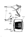
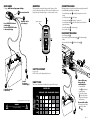
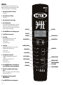
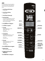
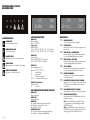
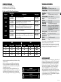
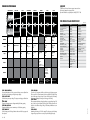
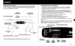
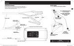
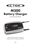
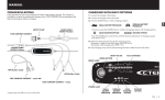
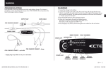
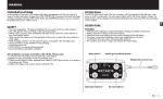
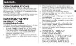
CONGRATULATIONS
on the purchase of your new professional switch mode battery charger.
This charger is included in a series of professional chargers from
CTEK SWEDEN AB and represents the latest technology in battery
charging. MXTS 40 is a charger with multiple adjustable parameters.
SAFETY
•The charger is designed for charging only batteries according to the
technical specification. Do not use
the charger for any other purpose.
Always follow battery manufacturers recommendations.
•Never try to charge non rechargeable batteries.
•Check the cables prior to use. Ensure
that no cracks have occurred in
the cables or bend protection. A
charger with damaged cables must
not be used. A damaged cable must
be replaced by an original part supplied by CTEK.
•Never charge a damaged battery.
•Never charge a frozen battery.
•Never place the charger on top of
the battery when charging.
•Always provide for proper ventilation during charging.
•Avoid covering the charger.
•A battery being charged could emit
explosive gases. Prevent sparks close
to the battery.
•All batteries fail sooner or later. A
battery that fails during charging is
normally taken care of by the charg-
ers advanced control, but some
rare errors in the battery could still
exist. Don’t leave any battery during
charging unattended for a longer
period of time.
•Ensure that the cabling does not
jam or comes into contact with hot
surfaces or sharp edges.
•Battery acid is corrosive. Rinse immediately with water if acid comes into
contact with skin or eyes, seek immediate medical advice.
•Always check that the charger has
switched to STEP 7 before leaving the
charger unattended and connected
for long periods. If the charger
has not switched to STEP 7 within
55 hours, this is an indication of
an error. Manually disconnect the
charger.
•Batteries consume water during use
and charging. For batteries where
water can be added, the water level
should be checked regularly. If the
water level is low add distilled water.
•(IEC 7.12 ed.5) This appliance is not
intended for use by persons (including children) with reduced physical,
sensory or mental capabilities, or
lack of experience and knowledge,
unless they have been given supervision or instruction concerning use of the appliance by a person
responsible for their safety. Children
should be supervised to ensure that
they do not play with the appliance.
(EN 7.12) This appliance can be used by
children aged from 8 years and above
and persons with reduced physical,
sensory or mental capabilities, or
lack of experience and knowledge if
they have been given supervision or
instruction concerning use of the
appliance in a safe way and understand the hazards involved. Children
shall not play with the appliance.
Cleaning and user maintenance
shall not be made by children without supervision.
•Connection to the mains supply
must be in accordance with the
national regulations for electrical
installations.
•CHARGERS WITH GROUNDED MAINS
PLUG MUST ONLY BE CONNECTED TO A
GROUNDED SOCKLET OUTLET.
•DON´T PLACE A FAN-COOLED CHARGER
SO THAT DUST, DIRT OR SIMILAR CAN BE
SUCKED INTO THE FAN.
•chargers with ip-class lower than
ipx4 are DESIGNED FOR INDOOR USE.
see technical specification. DO NOT
EXPOSE TO RAIN OR SNOW.
EN • 3
EN
MANUAL
Clamps
Eyelets M6
Temperature sensor
CORD SET PRO
CORD SET PRO
female connector +
Charger cable
male connector +/-
USB Type B contact
Temperature sensor
female connector
Temperature sensor
male connector
1
2
AGM
NORMAL
Ca/Ca
3
SUPPLY
BOOST
CORD SET PRO
female connector -
4
5
SET
STOP
6
7
8
12V/40A
24V/20A
Mains cable connector/
Mains switch
4 • EN
MXTS 40
MODE
START
STOP
Mains cable
To charge, with last used program settings
5
4
Turn on mains switch
When permanently mounting the charger, mount the charger on a firm
surface. Fix the charger with screws in the four holes. Use suitable screws or
fixings. Allow space around the charger to not interfere with air cooling.
1
Press START/STOP-button to
start charging
Press the START/STOP-button
to interrupt charging
Attach the cables
to the charger
USB TYPE B CONTACT
MXTS 40
12V/40A
24V/20A
1
2
3
4
5
6
7
• Turn off mains switch 6 .
• Disconnect the charger from the mains supply 5 before disconnecting the
battery.
• Disconnect the black clamp 4 before the red clamp 3 .
SET
MODE
Ca/Ca
BOOST
STOP
If the battery clamps are incorrectly connected, the reverse polarity protection will
ensure that the battery and charger are not damaged.
• Connect the battery cables 1 , including the temperature sensor, to the
charger.
• Connect the mains cable 2 to the charger.
• Connect the red clamp 3 to the battery´s positive pole.
• Connect the black clamp 4 to the vehicle chassis remote from the fuel
pipe and the battery.
• Connect the charger 5 to the mains supply.
• Turn on mains switch 6 .
DISCOnnect the cables
8
NORMAL
AGM
COnnect the cables
START
STOP
SUPPLY
6
–
2
+
3
USB TYPE B CONTACT
For service only.
NOTE: Not to be used to charge mobile phones etc.
1
Connect
the charger
to mains supply*
2
Some vehicles may
have positively
earthed batteries
• Connect the black
clamp 3 to the battery´s
negative terminal.
• Connect the red clamp
4 to the vehicle chassis
remote from the fuel pipe
and the battery.
READY TO USE
Table shows estimated time to take battery from empty to 80% charged.
BATTERY SIZE
Connect the charger
to the battery
10Ah 20Ah 50Ah 100Ah 600Ah 1200Ah
*Supply plugs may differ to suit your mains supply.
WARNING!
Batteries and electronics will be damaged if 12V batteries
are charged in 24V-setting.
CHARGING
CURRENT
5A
3h
8h
2h
4h
8h
2h
4h
24h
30A
3h
16h
40A
2h
12h
10A
20A
2h
3
24h
4
Disconnect the cables
• Disconnect the red clamp
4 before the black
clamp 3 .
5
EN • 5
EN
MOUNTING
QUICK GUIDE
charging
For best possible charging of your batteries the voltage and current is
adjustable. In addition temperature compensated charging is selectable.
See below how to set the parameters for customized charging.
MXTS 40
12V/40A
24V/20A
1. Connect the charger cables to the charger
(see quickguide).
2. Connect the charger to the battery
(see quickguide).
3. Connect the charger to the mains supply
4. Turn on the mains switch
The power lamp will indicate that the mains cable is connected to the
mains supply. The error lamp will indicate if the battery clamps are
incorrectly connected. The reverse polarity protection will ensure that
the battery or charger will not be damaged.
1
7. Select voltage
•Display (h) will indicate that voltage ( V) is selectable.
•Display (V) will flash and indicate set voltage.
•Press +/- to change.
•Press SET-button to confirm.
8. Select current
•Display (Ah & info) will indicate that current ( A) is selectable.
•Display (A) will flash and indicate set current.
•Press +/- to change.
•Press SET-button to confirm.
9. Select temperature compensation
•Display (h) will indicate that temperature compensation ( T) is
selectable.
•Display (Ah & info) will indicate On/ Off.
•Press +/- to change.
•Press SET-button to confirm.
10. Press the START/STOP-button to start charging cycle
or press MODE-button to change charging program
11. Follow the 8-step display through the charging
process
The battery is ready to start the engine when STEP 4 is lit. The battery
is fully charged when STEP 7 is lit.
12. Stop charging at any time by pressing the
START/STOP-button
13. Press START/STOP-button to start charging cycle
6 • EN
3
4
5
6
7
8
DISPLAY (V)
5. Press the MODE-button to select charging program
6. Press SET-button to set parameters
2
DISPLAY (h)
SET-button
DISPLAY (a)
12V
40A
0.00h
0Ah
DECREASE BUTTON
DISPLAY (ah & info)
INCREASE BUTTON
SET
NORMAL PROGRAM
AGM PROGRAM
Ca/Ca PROGRAM
BOOST PROGRAM
SUPPLY PROGRAM
ERROR lamp
POWER lamp
MODE-button
NORMAL
MODE
AGM
Ca/Ca
START/STOP-button
BOOST
STOP
SUPPLY
START
STOP
REVERSED POLARITY
BATTERY TEMPERATURE
OUT OF RANGE
OVERVOLTAGE ERROR
SUPPLY
For best possible float maintenance charging or voltage supply function
for the vehicle the voltage and max current limit are adjustable from the
front panel. See below how to set the voltage supply program and it's
parameters.
MXTS 40
12V/40A
24V/20A
EN
1. Connect the charger cables to the charger
(see "Cable connection").
2. Connect the charger to the battery
(see "Cable connection").
3. Connect the charger to the mains supply
4. Turn on the mains switch
The power lamp will indicate that the mains cable is connected to the
mains supply. The error lamp will indicate if the battery clamps are
incorrectly connected. The reverse polarity protection will ensure that
the battery or charger will not be damaged.
DISPLAY (V)
5. Press the MODE-button to select Supply mode
DISPLAY (h)
6. Press SET-button to set parameters
SET-button
7. Select voltage
•Display (h) will indicate that voltage ( V) is selected.
•Display (V) will indicate set voltage.
•Press +/- to change.
•Press SET-button to confirm.
8. Select Supply voltage
•Display (h) will indicate that Supply voltage ( SV) is selected.
•Display (V) will flash and indicate Supply voltage level.
•Press +/- to change.
•Press SET-button to confirm.
9. Select current
•Display (Ah & info) will indicate that current ( A) is selected.
•Display (A) will flash and indicate set current.
•Press +/- to change.
•Press SET-button to confirm.
10. Press the START/STOP-button to start Supply mode
11. Supply mode indication
STEP 7 is lit to indicate that Supply mode is running.
1
2
3
4
5
6
7
8
DISPLAY (a)
12V
40A
0.00h
0Ah
DECREASE BUTTON
DISPLAY (ah & info)
INCREASE BUTTON
SET
NORMAL PROGRAM
AGM PROGRAM
Ca/Ca PROGRAM
BOOST PROGRAM
SUPPLY PROGRAM
ERROR lamp
POWER lamp
MODE-button
NORMAL
MODE
AGM
Ca/Ca
START/STOP-button
BOOST
STOP
SUPPLY
START
STOP
REVERSED POLARITY
BATTERY TEMPERATURE
OUT OF RANGE
OVERVOLTAGE ERROR
12. Stop Supply at any time by pressing the
START/STOP-button
13. Press START/STOP-button to start Supply mode
EN • 7
6
7
8
NORMAL
BOOST
INDICATION LAMPS, DISPLAYS
MODE START
STOP
STOP
AGM
AND ERROR
CODES
NORMAL
SUPPLY
SET
Ca/Ca
AGM
SET
Ca/Ca
STOP
BOOST
M
SUPPLY
MODE
STOP
Ca
START
STOP
START
STOP
SUPPLYMODE
INDICATION LAMPS:
OST
START LAMP
POWER
STOP
MODE STOP Power
connected and switched on.
PPLY
STOP
START
GENERAL ERROR LAMP
STOPAn error has been detected.
START
STOP
2
3
4
5
6
7
8
POLARITY ERROR
Reversed polarity or short circuit in charge cables error.
BATTERY ERROR
Battery temperature error. The battery is too hot to charge.
BATTERY VOLTAGE ERROR
Overvoltage error on battery connection.
2
3
4
5
6
7
8
12V
40A
24V
20A
0.00h
0Ah
Error:
E07
SETTINGS BEFORE START:
DISPLAY (V)
SET
Indicates voltage set
Options: 12/ 24Volts
Supply voltage
Indicates voltage set
Options: 13,6/14,0/14,4/14,8V in 12V setting
Options: 27,2/28,0/28,8/29,6V in 24V setting
NORMAL
DISPLAY (A)
Indicates current set
Options: 40/ 30/ 20/ 10A in 12V setting MODE
/ 10/ 5A in 24V setting
Options: 20/ 15AGM
ERROR CODES:
E01 REVERSE POLARITYSET
Connect the charger according to “quickguide”.
E02 OVER VOLTAGE
Battery voltage too high for the chosen charging program, check
battery voltage.
E03 TIME OUT STEP 1: DESULPHATION
Restart the
charger. If charging is still being interrupted the batNORMAL
tery is seriously sulphated and may need to be replaced.
E04 TIME OUT STEP 2: SOFT START MODE
AGM
Restart the
charger. If charging is still being interrupted the battery
can not accept charge and may need to be replaced.
DISPLAY (h)
Indicates which parameter
Ca/Ca to set
Options: V/ SV/ A/T/ RT[h]
V
= Nominal Voltage
SV
= SupplyBOOST
Voltage
START
T
= Temperature compensation
RT[h] = Recond time in BOOSTSTOP
program STOP
E05 STEP 5: ANALYSE
SUPPLY
DISPLAY (h) + (Ah
& info)
Displays error codes
A
= Current limit
Battery voltage too low or too large consumers connected. Check
if 12V battery connected in 24V battery setting or disconnect
large consumers.
REAL TIME INDICATION DURING CHARGING:
DISPLAY (V)
Displays output voltage
DISPLAY (A)
Displays output current
DISPLAY (h)
Alt. 1. Displays total elapsed charging time (minutes/hours)
Alt. 2. Displays time elapsed until error occured
Alt. 3. Displays error message
DISPLAY (Ah & info)
Alt.1. Displays total charge delivered since start (minutes/hours)
Alt.2. Displays error codes together with ERROR lamp
8 • EN
1
MODE
BOOST
RMAL
1
Ca/Ca
Restart the
charger. If charging is still being interrupted the battery cannot retain charge and may need to be replaced.
E06 BATTERY OVERHEATED
BOOST
The battery
is too hot to charge. The battery
is damaged and
START
may need to be replaced. STOP
STOP
VOLTAGE IN SUPPLY PROGRAM
E07 LOW BATTERY
SUPPLY
E08 HIGH CURRENT IN SUPPLY PROGRAM
Check if clamps are short circuited or connected reversed polarity.
E99 OVER VOLTAGE PROTECTION
If battery voltage is below 17V the ERROR lamp is lit when 24V
setting has been selected.
Alt 1. Press START/STOP button to charge with 12V setting.
To set the parameters for customized charging proceed with
“CHARGING” step 6 to 9.
Alt 2. Press INCREASE button to change to 24V setting. Press
START/STOP button to resume. To set the parameters for customized charging proceed with “CHARGING” step 6 to 9.
TECHNICAL SPECIFICATION
Choose program by pressing the MODE-button.
Adjust parameters according to "CHARGING" (6–9).
Press START/STOP button to start the selected program.
The table explains the different Charging Programs:
Program
Battery Size
(Ah)
Normal
20–1200Ah
10–600Ah
Use for GEL, WET and MF batteries.
-20°C–+50°C
(-4ºF–+122ºF)
AGM
20–1200Ah
10–600Ah
Use for most AGM batteries. Some AGM should use lower voltage
(NORMAL Mode), check battery manual if unsure.
-20°C–+50°C
(-4ºF–+122ºF)
Ca/Ca
20–1200Ah
10–600Ah
Use for Ca/Ca batteries. Use Ca/Ca program to maximize charge with
minimum loss of fluid. Including RECOND step. Recond your battery once
per year and after deep discharge to maximise lifetime and capacity.
-20°C–+50°C
(-4ºF–+122ºF)
BOOST
20–1200Ah
10–600Ah
Supply
20–1200Ah
10–600Ah
Explanation
Temp range
Used for recovery of stratified batteries.
-20°C–+50°C
(-4ºF–+122ºF)
Use as power supply or use for float maintenance charging when 100%
capacity of the battery is required. SUPPLY program activates step 7 without
time or voltage limitation.
12V
-20°C–+50°C
(-4ºF–+122ºF)
24V
Current
Battery size Min
Battery size Max
Current
Battery size Min
Battery size Max
10A
20Ah
300Ah
5A
10Ah
150Ah
20A
40Ah
600Ah
10A
20Ah
300Ah
30A
60Ah
900Ah
15A
30Ah
450Ah
40A
80Ah
1200Ah
20A
40Ah
600Ah
Model number
Rated Voltage AC
Charging voltage
1069
220–240VAC, 50–60Hz, 3.0A
14.4V/14.7V/15.8V and 28.8V/29.4V/31.6V
Start voltage
Output
Back current drain*
Ripple**
Ambient
temperature
Charger type
Battery types
2.0V
Selectable, max 40A/12V or 20A/24V
Less than 1Ah/month
Less than 4% of actual DC current
-20°C to +50°C
(-4°F to +122°F)
8 step fully automatic charging cycle
All types of 12V and 24V lead-acid batteries
(WET, MF, Ca/Ca, AGM and GEL). Check
with your battery supplier for appropriate
charge information
12V: 20–1200Ah, 24V: 10–600Ah
254 x 160 x 76mm (L x W x H)
IP20
1.3kg without charge cable
2 years
Battery capacity
Dimensions
Insulation class
Weight
Warranty
*) Back current drain is the current that drains the battery if the charger is not connected
to the mains. CTEK chargers have a very low back current.
**) The quality of the charging voltage and charging current is very important. A high
current ripple heats up the battery which has an aging effect on the positive electrode.
High voltage ripple could harm other equipment that is connected to the battery. CTEK
battery chargers produce very clean voltage and current with low ripple.
LIMITED WARRANTY
•Using higher current than recommended may result in batteries not being
completely charged.
•Using lower current than recommended will prolong the charging time.
•The currents are the maximum recommended current for battery charging. If a parallel consumer is connected then the current setting could be
increased with this current value.
•Some battery manufacturer could recommend different values. Please
check with the manufacturer if uncertain. The main recommendations are
that Gel batteries should be charged in the lower current range, Power
AGM’s in the upper range and most other battery types in the mid-range.
WARNING!
Risk of short circuiting the battery cables. Connect charger cables
to the charger before connecting the battery
WARNING!
Risk of electrical shock if touching positive and negative terminals
when charging
CTEK SWEDEN AB, issues this limited warranty to the original purchaser of
this product. This limited warranty is not transferable. The warranty applies
to manufacturing faults and material defects for 2 years from the date of
purchase. The customer must return the product together with the receipt
of purchase to the point of purchase. This warranty is void if the battery
charger has been opened, handled carelessly or repaired by anyone
other than CTEK SWEDEN AB or its authorised representatives. The
charger is sealed. Removing or damaging the seal will void the warranty.
CTEK SWEDEN AB makes no warranty other than this limited warranty and
is not liable for any other costs other than those mentioned above, i.e. no
consequential damages. Moreover, CTEK SWEDEN AB is not obligated to
any other warranty other than this warranty.
EN • 9
EN
CHARGING programs
CHARGING programS
BULK
ABSORPTION
ANALYSE
RECOND
FLOAT
PULSE
CTEK productS ARE protected by
11
CURRENT (A)
NORMAL
AGM
Ca/Ca
2
15.8V
31.6V
40A until 12.6V
20A until 25.2V
15.8V
31.6V
40A until 12.6V
20A until 25.2V
15.8V
31.6V
40A until 12.6V
20A until 25.2V
3
Increasing voltage to
14.4V
28.8V
40A
20A
Increasing voltage to
14.7V
29.2V
40A
20A
Increasing voltage to
14.7V
29.4V
40A
20A
4
5
8
Checks if voltage
drops to below
12V
24V
13.6V
27.2V
40A
20A
12.7V–14.4V
25.4V–28.8V
40A–2A
20A–2A
14.7V
29.2V
Declining current
Checks if voltage
drops to below
12V
24V
13.6V
27.2V 40A
20A
12.7V–14.4V
25.4V–28.8V
40A–2A
20A–2A
14.7V
29.4V
Declining current
Checks if voltage
drops to below
12V
24V
13.6V
27.2V 40A
20A
12.7V–14.4V
25.4V–28.8V
40A–2A
20A–2A
Max 15.8V
Max 31.6V
1.5A
Increasing voltage to
15.8V
31.6V
1.5A
Selectable timer,
Initially 8h. Max 24h.
Selectable
13.6; 14.0;
14.4; 14.8V
27.2; 28.0
28.8; 29.2V
40A
20A
SUPPLY
8 hours
20 hours
8 hours
STEP 1 desulphation
Detects sulphated batteries. Pulsing current and voltage, removes sulphates from
the lead plates of the battery restoring the battery capacity.
STEP 2 soft start
Tests if the battery can accept charge. This step prevents charging a defective battery.
STEP 3 bulk
Charging with maximum current until approximately 80% battery capacity.
STEP 4 absorption
Charging with declining current to maximize up to 100% battery capacity.
STEP 5 analysE
Tests if the battery can hold charge. Batteries that cannot hold charge may need
to be replaced.
10 • EN
7
6
14.4V
28.8V
Declining current
BOOST
Time limit:
CTEK offers professional customer support: www.ctek.com.
For latest user manual see www.ctek.com.
By e-mail: [email protected], by telephone: +46(0) 225 351 80.
3 minutes
2 hours or 6 hours
depending on battery voltage at
charge start
10days
(Supply unlimited
time)
2012–05–30
Patents
Designs
Trade marks
EP10156636.2 pending
US12/780968 pending
EP1618643
US7541778
EP1744432
EP1483817 pending
SE524203
US7005832B2
EP1716626 pending
SE526631
US7638974B2
EP09180286.8 pending
US12/646405 pending
EP1483818
SE1483818
US7629774B2
EP09170640.8 pending
US12/564360 pending
SE528232
SE525604
RCD 509617
US D575225
US D580853
US D581356
US D571179
RCD 321216
RCD 000911839
RCD 081418
RCD 001119911-0001
RCD 001119911-0002
RCD 081244
RCD 321198
RCD 321197
ZL 200830120184.0
ZL 200830120183.6
RCD 001505138-0001
RCD 000835541-0001
RCD 000835541-0002
D596126
D596125
RCD 001705138-0001
US D29/378528 pending
ZL 201030618223.7
US RE42303
US RE42230
TMA 669987
CTM 844303
CTM 372715
CTM 3151800
TMA 823341
CTM 1025831
CTM 405811
CTM 830545751 pending
CTM 1935061 pending
V28573IP00
CTM 2010004118 pending
CTM 4-2010-500516
CTM 410713
CTM 2010/05152 pending
CTM1042686
CTM 766840 pending
Max 1h pulse
STEP 6 recond
Choose the Ca/Ca program to add the recondition step to the charging program.
This step can also be selected separately by choosing the BOOST-program. During
the recondition step voltage increases to create controlled gassing in the battery.
Gassing mixes the battery acid and gives back energy to the battery.
STEP 7 float
This step maintains the battery voltage by providing a constant voltage charge. This
step can also be selected separately by choosing the SUPPLY-program where it is
possible to select different voltage settings. Follow battery manufacturers recommendation.
STEP 8 pulse
Maintaining the battery at 95–100% capacity. The charger monitors the battery
voltage and gives a pulse when necessary to keep the battery fully charged.
20019374C
SOFT START
VOLTAGE (V)
DESULPHATION
SUPPORT