1
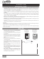
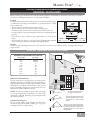
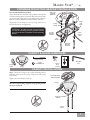
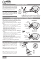
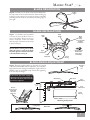
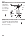
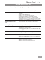
Malibu Star® Malibu Star® Owner’s Manual READ AND SAVE THESE INSTRUCTIONS! SAFETY FIRST: Safety and the proper operation of your Casablanca fan both require a thorough knowledge of the product and proper installation. Therefore, before attempting to install and operate your Casablanca fan, read this Owner’s Manual completely and carefully. Retain the manual for future reference CAUTION: To avoid possible electrical shock, make certain that electricity is turned off at the circuit breaker or fuse box before attempting any installation procedure. CONTENTS INTRODUCTION Before You Start Safe Use 2 2 MOUNTING RECOMMENDATIONS General Guidelines.......................................................................................................................................................... 3 Sloped Ceiling Installations............................................................................................................................................. 3 FAN INSTALLATION Perma®Lock Hardware.................................................................................................................................................... 4 Fan Preparation................................................................................................................................................................ 4 Ceiling Hardware ............................................................................................................................................................ 4 Getting StartedCanopy Installation................................................................................................................................. 4 Crossbar Mounting Bracket Installation.......................................................................................................................... 5 Canopy & Blade Hardware.............................................................................................................................................. 5 Canopy Installation ......................................................................................................................................................... 5 Hanging the Fan.............................................................................................................................................................. 6 Canopy Electrical Connections........................................................................................................................................ 6 Canopy Hatch Installation............................................................................................................................................... 6 Blade Orientation............................................................................................................................................................. 7 Blade Installation............................................................................................................................................................. 7 Blade Adjustment Angle.................................................................................................................................................. 7 WALL CONTROL W-80 or W-81 Wall Control for Fan and Lights............................................................................................................. 8 W-80 or W-81 Wall Control Operation.......................................................................................................................... 8 TROUBLESHOOTING TIPS............................................................................................................................................. 9 CARE RECOMMENDATIONS....................................................................................................................................... 10 PRODUCT SPECIFICATIONS........................................................................................................................................ 10 PN 2343010 AT0109 1 INTRODUCTION BEFORE YOU START • CAUTION: RISK OF ELECTRICAL SHOCK! Installation is to be in accordance with the National Electrical Code, ANSI/NFPA 70-1999 and local codes. If you are unfamiliar with the wiring codes, you should use a qualified electrician. To avoid overheating and possible damage to other equipment, do not install control to a receptacle, fluorescent light fixture, motor operated appliance, or transformer-supplied appliance. • This fan is designed to be installed on an existing electrical outlet box. The outlet box must be UL Listed for ceiling fan installations, if it is not, a new box must be installed. Casablanca extension poles are available for sloped or high ceiling installations. • This ceiling fan requires a grounded electrical supply of 120 VAC, 60 Hz and a minimum 15 amp circuit. The maximum current requirement for the fan with light fixture is 3.0 amps. The fan uses about 1 amp or 100 watts. Maximum light current is 2.0 amps or 240 watts of lighting. • Where wire nuts are employed, be sure all bare wires are within the connectors. When installing the canopy hatch, make sure all wires are within the canopy and that no wires are being pinched. • WARNING: Do not bend the blade brackets when installing the brackets, balancing the blades or cleaning the fan. Do not insert foreign objects in between the rotating fan blades. • WARNING: To reduce the risk of fire or electric shock, do not use this fan with any solid state speed control device. Use only the control provided with or recommended for this fan.. Unpacking Before assembling and installing your ceiling fan, remove all parts from the shipping cartons and check them against the parts listed here. Before discarding packaging material, be certain that all parts have been removed. NOTE: For best performance and for your warranty to be valid, use only genuine Casablanca Fan Company blades, light fixtures, and accessories. SAFE USE • Inspect the contents of your carton for possible shipping or handling damage and report any such damage directly to your authorized Casablanca dealer. • It is always a good idea to have an assistant to help with the installation. • The blades in each pack are matched for equal weight to assure smooth fan operation. If more than one fan is being installed, be careful not to mix blades from different cartons. • Never install a fan over a pool or spa. • For safety reasons, the fan blades must be a minimum of 7 feet above the floor. • In any installation, the tips of the blades must be at least 18 inches from the wall in order to provide sufficient clearance for the blades. • Never insert anything into the path of the fan blades while the fan is in operation. • When cleaning, painting, or working near your fan, be very careful of the fan and blades. Always turn the power OFF to the ceiling fan before servicing it, working on it, or replacing lightbulbs. • Never operate a fan that has been damaged in any way. For assistance in obtaining service, call Casablanca Fan Company toll-free at 1-888-227-2178 or contact your local Casablanca Authorized Dealer. 2 FUSE BOX CIRCUIT BREAKER Remove the fuse for the circuit you will be working on Trip the breaker for the circuit you will be working on 18″ 84″ Malibu Star® MOUNTING RECOMMENDATIONS GENERAL GUIDELINES Before mounting your Casablanca fan, read the following helpful recommendations. The location of the fan, air circulation, and fan size are all important factors to consider before installation. Location Ceiling fans have practical uses in almost every room in your home. We suggest you follow these mounting recommendations as you decide where to install your Casablanca fan. • This fan requires a minimum ceiling height of 9 feet. • Do not locate the fan in a doorway or above a swinging door. • In bedrooms, fans work best when mounted above the foot of the bed. • Over pool tables, be sure to provide plenty of clearance to avoid damage from pool cues. • In kitchens, be sure to allow for open cupboard doors to clear the fan blades. • Do not install a fan close to, or over, a pool or spa. High humidity combined with corrosive gases will destroy the finish and warp the blades. Fan Size Variable fan speed capability permits the use of a full-size 54-inch fan even in smaller rooms. For very large rooms, two fans may be needed. SLOPED CEILING INSTALLATIONS SUGGESTED EXTENSION POLE LENGTHS Ceiling Height Pole Length 8′ 0” 8′ 6” 9′ 0” 9′ 6” 10′ 0” 11′ 0” 12′ 0” 13′ 0” 14′ 0” standard standard 6” 12” 12” 18” 24” 36” 48” Maximum Angle 32º Extension Pole Blades must be a minimum of 7′ above the floor 7’ minimum When to Use Extension Poles For best performance and appearance, an extension pole should be used with your Casablanca fan when installing on high (cathedral) ceilings or sloped ceilings. Casablanca offers standard poles in increments of 6 inches up to 5 feet. Custom poles are available in lengths up to 9 feet 9 inches. See your Authorized Casablanca Dealer for details. NOTE: The fan may wobble or vibrate if the pole length is not long enough and the inside blade is too close to the downslope or side wall. Extending the pole length usually will solve the problem. Calculation of 32 Degrees Use the tear-off Ceiling Angle Template card inserted in this manual. It provides you with a simple “go” or “no go” for installing your fan on a sloped ceiling. EXAMPLE 1 This slope is less than 32 degrees. It is okay to install your fan. EXAMPLE 2 This slope is 32 degrees, the maximum slope that will allow the fan to hang straight down. It is okay to install your fan. EXAMPLE 3 This slope is more than 32 degrees.Your fan will not hang straight down; an adaptor is necessary. Contact your local Authorized Casablanca Dealer to purchase a “Sloped Ceiling Adaptor.” 3 FAN INSTALLATION Unpacking: Before assembling and installing your ceiling fan, remove all parts from the shipping cartons and check them against the parts listed here. Before discarding packaging material, be certain that all parts have been removed. IMPORTANT NOTE - CEILING HEIGHT This fan is designed for installation on ceilings with a minimum height of 10 feet from the floor. The large blades require the use of the 12” extension pole to allow for proper air flow and ventilation. PERMA*LOCK HARDWARE Allen Set Screw 1/4-20 x 1/4” (pre-installed) Downrod & Ball Assembly 3mm Allen Wrench FAN PREPARATION IMPORTANT SAFETY INFORMATION! Before starting the installation of your ceiling fan, install the threaded downrod into the motor coupling and lock the assembly Prepare for fan installation as follows: Motor Wires Step 1a. Route the wires from the motor through the Perma•Lock™ downrod and ball assembly. Tip: The downrod has a tapered thread that is designed to lock completely when correctly installed. Step 1b. Using the provided Allen wrench, loosen the set screw several turns to allow installation of the downrod. Thread the downrod into the motor coupling until it stops turning. This will take at least four and a half full turns. Tapered Thread Allen Set Screw Ground Wire Downrod & Ball Assembly Motor Coupling Step 1c. Tighten the set screw securely with the provided Allen wrench to ensure safe operation of your fan. CAUTION: Failure to fully lock in the downrod before securely tightening the Allen set screw may cause the fan to separate from the downrod during normal operation! CEILING HARDWARE Crossbar Mounting Bracket Wire Nut (4) ADDITIONAL HARDWARE 2-1/4 x 8-32 Rounded Head Screw (2) 1 x 8-32 rounded head screw (2) Flat Washer (2) GETTING STARTED Installing a New Ceiling Fixture Outlet Box If you do not have an existing fixture located where you wish to place your Casablanca fan, an approved ceiling fixture outlet box must be installed and wired. Warning: To reduce the risk of fire, electrical shock, or personal injury, mount to outlet box marked acceptable for ceiling fan support using the mounting hardware provided with the outlet box. 4 Using Existing Ceiling Fixture Outlet Box After turning the power OFF at its source (either circuit breaker or fuse box), lower the old fixture and disconnect the wiring. Check the ceiling fixture outlet box to be sure that it is marked ‘Approved for ceiling fan mounting’. If it is not, a new box must be installed. Malibu Star® CROSSBAR MOUNTING BRACKET Installation Proceed with installation as follows: Step 2. Route the wires from the ceiling outlet box through the crossbar mounting bracket center hole. Attach the bracket, with ground wire and ridges down, to the ceiling fixture outlet box with the mounting hardware included with the outlet box. Tighten the screws firmly by hand only, being careful not to bend the bracket by over tightening. CAUTION: To reduce the risk of personal injury, use only the mounting hardware provided with the approved outlet box to install the crossbar mounting bracket. Ceiling Fan Approved Outlet Box Ridge Side Down Ceiling Wiring Crossbar Mounting Bracket Green Ground Wire Flat Washer Outlet Box Mounting Hardware CANOPY & BLADE HARDWARE Canopy Screw (4) Canopy Hatch Canopy Lock Washer (4) Canopy Wire Nut (3) Allen Hex Key W-80 or W-81 Control CANOPY Installation Step 3. Attach the canopy to the crossbar mounting bracket with three of the 8-32 x 2-½ long canopy screws and canopy lock washers. Tighten the screw firmly by hand only. NOTE: On sloped ceilings, align the canopy opening towards the top or room peak. Crossbar Mounting Bracket Installed Canopy Canopy Lock Washers Canopy Screws 5 HANGING THE FAN Step 4. To hang the fan body in the canopy, hold the fan body firmly and insert the ball into the canopy opening. Check that no wires were pinched. Rotate the fan body until the slot in the ball fits into the pin opposite the canopy opening. Note: Independent control of the light fixture using a W-80 or W-81 requires an additional independent power wire run from the wall switch to the fan. See Page 7 for wiring. Capped Blue D-1 Option Wire on 3-Speed Only for Independent W-81 Light Control Ball Slot Pin DO NOT attempt to attach the blades until after the fan body is attached to the ceiling and Steps 5, 6, 7 and 8 are completed. CANOPY ELECTRICAL CONNECTIONS Step 5. Attach the fan wires to the ceiling fixture outlet box wiring by twisting the bare ends of the wires together and then securing with a wire nut. Test that the connection is secure by pulling on the wire nut. Connect in this order: Capped D1-Option Wire Step 6a. W-80or W-81 Wiring Connections - NO light fixture • GREEN leads from mounting plate and fan to GROUND conductor of power source. Secure with wire nut. • WHITE wire from fan to white NEUTRAL wire in ceiling fixture outlet box. Secure with wire nut. • BLACK power wire from fan to RED wire from W-80 in ceiling outlet box. Secure with wire nut. • Cap BLUE D-1 Option wire with wire nut. Step 6b. W-80 or W-81 Wiring Connections - WITH light fixture • GREEN leads from mounting plate and fan to GROUND conductor of power source. Secure with wire nut. • WHITE wire from fan to white NEUTRAL wire in ceiling fixture outlet box. Secure with wire nut. • BLACK power wire from fan to RED wire from W-80 in ceiling outlet box. Secure with wire nut. • BLUE wire from fan to YELLOW wire from W-80 in ceiling outlet box. Secure with wire nut. W-81 Connections No Light Fixture Black & Red Wires 2 White Wires 3 Green Wires Wire Nut Blue & Yellow Wires W-81 Connections With Light Fixture Black & Red Wires 2 White Wires 3 Green Wires NOTE: See page 7 for additional wiring information. CANOPY HATCH INSTALLATION Step 7. Tuck the wires into the canopy with the wire nuts pointed upwards, so that the WHITE and BLACK wires are on opposite sides of the canopy and all wires are clear of the canopy opening. Step8. Install canopy hatch with the last canopy screw and lock washer. To insert canopy screw, tilt the fan body away from the hatch opening. Step 9. Straighten the fan, then check to ensure that there is no movement between the canopy and ceiling or Hang-Tru ball and 12” extension tube. 6 Canopy Hatch Canopy Washer Canopy Screw Tilt the Fan to Install Last Canopy Screw Malibu Star® BLADE ORIENTATION Leading Edge Step 10. Orientation of fan blades. Note that the Malibu Star fan only rotates in the clockwise direction (when looking up at the fan on the ceiling). As you face the motor a fan blade extending from the motor to you will have its leading edge on your right. BLADE INSTALLATION Step 11. Use the allen wrench provided to loosen the four (4) allen screws on each of the blade clamps but do not remove completely. Insert each blade with the proper orientation (as described in previous Step 9). Blade Shaft Blade Holder Blade Holder Clamp Loosened Ready for Blade Installation Allen Key NOTE: Before securing the fan blade adjust the ‘pitch’ or angle of the blade for either upward or downward air flow, as described below in Step 11. Allen Hex Head Blade Holder Clamp Screw (4 Per Blade) Upper Chainwheel Lower Chainwheel Switch Housing BLADE ANGLE ADJUSTMENT Step 12. The pitch angle should be no more than 15° upward or downward. Each blade must be adjusted to the same pitch angle, otherwise the rotating fan will wobble. Tighten the four (4) allen screws on each blade clamp. Check after tightening to be sure they are all tight. CAUTION! DO NOT attempt to adjust the tension on wire holding the silk cloth in the blade. These have all been factory adjusted. 15° 7/8= 15° Max 1 Measure Between Upper Chainwheel and End of Blade Arm INCHE S Blade Holder Blade Shaft Maximum Angle ±15° Upper Chainwheel Lower Chainwheel Blade Arm 2 Switch Housing Blade Angle Adjustment Leading Edge Downward Airflow Airflow Direction Upward Airflow Leading Edge 7 Wall Control W-80 or W-81 WALL CONTROL FOR FAN & LIGHTS • The fan may be turned ON and OFF by the W-80 or W-81 wall control. • The lights may be turned ON and OFF by the W-80 or W-81 and the intensity adjusted from low to high. • The fan must be supplied with two independent 120V AC supply wires. You may have to contact a qualified electrician to have an additional 120V AC supply wire installed. • The W-80 or W-81 allows the choice of four different speed settings. MED LO OFF OFF MED HI W-80 OR W-81 WALL CONTROL HI MAX W-80 or W-81 W-80 or W-81 WALL CONTROL OPERATION The W-80 or W-81 wall control provides separate control of fan and light with two separate knobs from a convenient wall location. The W-80 or W-81 is designed to replace a standard wall switch and wall boxes with a depth of 2" or greater. Requires two hot leads from wall box to ceiling wiring box. To install a W-80 or W-81 wall control in place of an existing wall switch, follow the instructions on the W-80 or W-81 package. Operation of the fan from the wall switch is simple: 1.Turn the upper knob to the desired fan speed. 2.Turn the lower knob to the desired light setting. 8 MED LO OFF OFF MED HI HI MAX Malibu Star® TROUBLESHOOTING TIPS Please refer to this guide before requesting service or contacting your dealer for assistance. PROBLEM POSSIBLE REMEDIES Fan will not start • Check the main circuit fuses, circuit breakers, and wall switch position. Check all wire connections. Make sure the power is turned off during this inspection. Fan is noisy during operation • Check and tighten the light fixture retaining screws, glass shade screws, and/or lightbulb(s). • Tighten the blade to bladeholder screws. • Tighten the canopy screws and mounting plate assembly. • Check and tighten blade holders to flywheel (or direct drive motor). • Make sure all screws in the motor housing are snug but not overly tight. • Check that the wire nuts inside the canopy and switch housing are not touching the metal parts or have fallen off the wire splices. Tighten or adjust as necessary. Fan runs slowly in either direction • Defective reverse switch, defective capacitor, or open motor winding. Replace if rotation is started by hand; will not reverse switch assembly, replace PCB assembly, or replace motor unit. reverse Fan will not operate at proper speeds • Defective three-speed pull-chain switch assembly or defective capacitor. Replace or will not operate at any speed three-speed pull-chain switch assembly or replace PCB assembly. Fan wobbles or shakes excessively • Check that all blades are set to exactly the same angle by repeating the "Blade Angle Adjustment" instructions on page 7. • Check that all blades are installed correctly in the blade holder assembly so that their leading edge is facing the correct direction. See "Blade Orientation" section, Step 10, on page 7. All blades flap • Blade orientation has material as leading edge. Orient blades correctly, then set blade angle by repeating Steps 10 through 12 on page 7 starting with "Blade Orientation." One blade flaps • Blade wire tension is incorrect. Return blade set to factory for service refurbishment and repair. • Blade material is torn. Return blade set to factory for service refurbishment and repair. No airflow from fan • Blade angle is set flat. Orient blades correctly. • Blade angle is set for upward airflow. Orient blades correctly. • Blade angle is set too low. Orient blades correctly. 9 CARE RECOMMENDATIONS Fan Finishes • For cleaning, a soft brush or lint-free cloth should be used to prevent scratching the finish. • A vacuum cleaner brush nozzle can remove heavier dust. • Surface smudges or an accumulation of dirt and dust can be removed easily by using a mild detergent and slightly dampened soft cloth. An antistatic agent may be used, but never use abrasive cleaning agents as these will damage the finish. Blades • Dust regularly. If blades become dirty, remove from fan. Soak in bathtub filled with warm water and Woolite for 10 to 15 minutes. Rinse. Air dry. Reattach to fan. No Need for Lubrication • Never lubricate this fan! The precision motor at the heart of your Casablanca fan features sealed bearings that are lubricated for life. • Do not attempt to oil the motor. Changing Lightbulbs • Be sure to turn the power to OFF at the wall switch or circuit breaker before changing lightbulbs. • Replace bulbs with the same type as you removed from the light fixture. • The maximum wattage rating for compatible light kits is 240 watts. For questions or to locate the nearest Casablanca Authorized Service Center, call 1-888-2272178 toll-free, or visit us on the Web at www.casablancafanco.com. This device complies with Part 15 of the FCC rules. Operation is subject to the following two conditions: 1.This device may not cause harmful interference. 2.This device must accept any interference received, including interference that may cause undesired operation. This equipment has been tested and found to comply with the limits for a class B digital device, pursuant to Part 15 of the FCC rules. These limits are designed to provide reasonable protection against harmful interference in a residental installation. This equipment generates, uses, and can radiate radio frequency energy and, if not installed and used in accordance with the instructions, may cause harmful interference to radio communication. However, there is no guarantee that the interference will not occur in a particular installation. If this equipment does cause harmful interference to radio or television reception, which can be determined by turning the equipment off and on, the user is encouraged to try to correct the interference by one or more of the following measures: • Reorient or relocate the receiving antenna. • Increase the separation between the equipment and receiver. • Connect the equipment into an outlet on a circuit different from that to which the receiver is connected. • Consult the dealer or an experienced radio/TV technician for help. NOTE: Any changes or modifications to the transmitter or receiver not expressly approved by Casablanca Fan Company may void one’s authority to operate this remote control. PRODUCT SPECIFICATIONS Model name: Model number: Dimensions: NOTE: Dimension B includes light fixture and glass. Weight: 10 Malibu Star® 23B002 A = 21" B = 23" C = 3" D = 6.25" E = 5.60" 19 lbs. Motor: Blade span: Blade iron pitch: No. of blades: Technology: XLP-2000TM 84 inches 15° 5 4-Speed/W-80 or W-81 Airflow: Electric Use*: Airflow Efficiency*: 5,170 cfm 109 watts 47.7 cfm/watts * Performance data is for fan only. No lighting wattage is included.