1
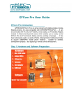
GSM Shield SIM900
Get Starting
This GPRS Shield is compatible with all boards which have the same form factor (and pinout) as a standard
Arduino Board. GPRS module delivers GSM/GPRS 850/900/1800/1900MHz performance for voice, SMS, Data,
and Fax in a small form factor.
The GPRS Shield is configured and controlled via its UART using simple AT commands. You can use the 2
jumper block to connect the SIM900 URAT post to any pins within D0-D3 (for Hardware/Software serial port).
EFCom not only can use the S_PWR button for power on, but also can use the digital pin (D6) of Arduino to
power on and reset (D5) the SIM900 module.
www.fut-elctronics.com
Page 1
Feature
Fully compatible with Arduino / Uno and Mega.
Free serial port connecting, you can select Hardware Serial port (D0/D1) control or Software Serial
port (D2/D3) control it.
SIM900 all pins breakout. Not just the UART port and debug port be layout, but also all pins on SIM900
be layout to the 2.54 standard pitch.
Super capacitor power supply for the RTC.
EFCom not only can use the button for power on, but also can use the digital pin of Arduino to power
on and reset the SIM900 module.
Quad-Band 850/ 900/ 1800/ 1900 MHz
GPRS multi-slot class 10/8
GPRS mobile station class B
Compliant to GSM phase 2/2+
Control via AT commands (GSM 07.07 ,07.05 and EFCOM enhanced AT Commands)
SIM application toolkit
Supply voltage range : 3.1 … 4.8V
Low power consumption: 1.5mA(sleep mode)
Operation temperature: -40°C to +85 °C
Dimension:68.33x53.09mm(Same dimension of Arduino main board)
Cautions
Make sure add using 9V Charger for power supply for your Arduino board and EFCom, The 9V
Charger we will provide to you with EFCom Shield. Because of the power supply range of SIM900 is
from 3.2V to 4.8V. The transmitting burst will cause voltage drop and the power supply must be
able to provide sufficient current up to 2A. The USB port cannot supply such a large current.
Make sure your SIM card is unlocked.
The product is provided as is without an insulating enclosure. Please observe ESD precautions
specially in dry (low humidity) weather.
The factory default setting for the GPRS Shield UART is 19200 bps 8-N-1. (Can be changed using AT
commands).
www.fut-elctronics.com
Page 2
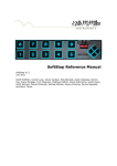
Hardware
Top-view
Super RTC Cap and Line In
LCD5100 interface and Software SerialPort Jumpe
www.fut-elctronics.com
Page 3
SIM Card Connector
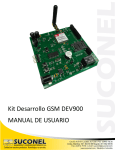
Light Status
LED
Status
Netlight
State
Off
On
Off
64ms On/800ms Off
64ms On/3000ms Off
64ms On/300ms Off
Function
Power Off
Power On
SIM900 is not working
SIM900 does not find the network
SIM900 find the network
GPRS communication
Getting Started
We will use tow methods
1. Using AT commands.
2. Using Arduino code (Uno – Mega) compatible .
Now we will prepare the Arduino board for communicating with the PC by UART protocol. Emulate a second
serial port (UART) using software on the digital pins D2 and D3 and patch through all the communication
between this second software serial port and the actual hardware serial port.
By doing this, all the data coming from the computer (connected to the actual hardware UART) would be
relayed as is to the GPRS Shield (connected to software UART).
Run Arduino IDE 1.0 or later
Open new sketch and write a below code.
SoftwareSerial mySerial(2, 3);
void setup()
{
mySerial.begin(19200);
Serial.begin(19200);
}
// the GPRS baud rate
// the GPRS baud rate
www.fut-elctronics.com
Page 4
void loop()
{
if (mySerial.available())
Serial.write(mySerial.read());
if (Serial.available())
mySerial.write(Serial.read());
}
Upload the sketch to the Arduino board.
Now all done to start use Arduino with either method
1.
Using AT commands.
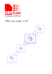
Open your favorite serial terminal software, choose the COM port for Arduino, set it to operate at
19200 8-N-1. I used” SSCOM “English edition.
Press and hold the power button a short while (Over 3 seconds) on the GPRS Shield to turn it on. Wait
half a minute for the GPRS Shield to connect to the network (Led Net will start blinking every 3
seconds or so). But there will not any information back in the monitor. If you want to see messages
from the shield in the serial monitor such as, you need disable auto-bauding mode, using
"AT+IPR=19200”. (Factory setting is AT+IPR=0 auto-bauding)
RDY
+CFUN: 1
+CPIN: READY
Call Ready
Now, type and send "AT" (without the quotes) followed by carriage return (enter key) to the Arduino board.
The GPRS Shield should respond by sending back an "OK". This would mean that you have been able to
successfully setup your GPRS Shield can now play around with various AT Commands. (If you are using the
readily available Serial Monitor in the Arduino IDE, you should set the line ending to "Carriage return" along
with a baud rate of 19200).
Sending a text message (SMS) –AT COMMAND
Install GSM shield in Arduino board and connect power cord.
Open your serial monitor program (I use SSCOM)
Through your serial terminal software, send AT+CMGF=1 and press the Enter key. The GPRS Shield can
send SMSes in two modes: Text mode and PDU (or binary) mode. Since we want to send out a human
readable message, we will select the text mode. The GPRS Shield will respond with an OK.
Send AT+CMGS="+XXXX6043032" and press the Enter key (include the quotes). This will instruct the
GPRS Shield to start accepting text for a new message meant for the phone number specified (replace
the number with the phone number of the target phone). The GPRS Shield will send a > signaling you
to start typing the message.
www.fut-elctronics.com
Page 5
Make a Call –AT COMMAND
Input ATD158********;
Respond OK, you will receive a call.
Input ATH to end a call
2. Using Arduino code (Uno – Mega) compatible
Sending a text message (SMS) –Arduino code
With the GPRS Shield removed, download this sketch into your Arduino. The GPRS Shield must be
removed so that it doesn't interfere with the programming of Arduino which takes place over the
Hardware UART (using FT232RL).
Disconnect the Arduino from USB port to remove power to it.
Set the Serial Port jumpers on the GPRS Shield in Xduino position (i.e. Arduino's RX connected to
GPRS_TX and TX of Arduino connected to GPRS_RX)
Connect the antenna to the GPRS Shield and insert the SIM Card.
Mount the GPRS Shield on Arduino.
Apply power to the Arduino using USB port or via external power supply.
Switch on the GPRS Shield by using the power switch. Wait till the Network LED (D1) starts blinking.
www.fut-elctronics.com
Page 6
Using a pen or a plastic tweezer access the reset switch on the Arduino Board and reset the
microcontroller to run the sketch from the start. Do not try resetting the Arduino by removing and
applying power to it as this will turn off the GPRS Shield.
If nothing goes wrong, the SMS will be received on receiver's handset.
void setup()
{
Serial.begin(19200); //Default serial port setting for the GPRS modem is 19200bps 8-N-1
Serial.print("\r");
delay(1000);
//Wait for a second while the modem sends an "OK"
Serial.print("AT+CMGF=1\r");
//Because we want to send the SMS in text mode
delay(1000);
//Serial.print("AT+CSCA=\"XXXX32055002 \"\r"); //Setting for the SMS Message center number,
//delay(1000);
//uncomment only if required and replace with
//the message center number obtained from
//your GSM service provider.
//Note that when specifying a tring of characters
// " is entered as \"
Serial.print("AT+CMGS=\"XXXX6043032\"\r"); //Start accepting the text for the message
//to be sent to the number specified.
//Replace this number with the target mobile number.
delay(1000);
Serial.print("SIM900 and Arduino say Hi!\r");
//The text for the message
delay(1000);
Serial.print(26,BYTE); //Equivalent to sending Ctrl+Z
}
void loop()
{
//We just want to send the SMS only once, so there is nothing in this loop.
//If we put the code for SMS here, it will be sent again and again and cost
us a lot.
}
Make a Call –Arduino code
#include <SoftwareSerial.h>
SoftwareSerial mySerial(2, 3);
void setup()
{
mySerial.begin(19200);
Serial.begin(19200);
// the GPRS baud rate
// the GPRS baud rate
delay(2000);
}
void loop()
www.fut-elctronics.com
Page 7
{
int count=0;
mySerial.println("ATD xxxxxxxxx;"); // xxxxxxxxx is the number you want to dial, Noice the ";" in the end
delay(2000);
while(1)
{
mySerial.println("AT+SPWM=2,63,100");// set PWM 2 PIN
delay(100);
mySerial.println("AT+SPWM=1,63,100");
delay(100);
mySerial.println("AT+SGPIO=0,1,1,1");// set GPIO 1 PIN to 1
delay(100);
mySerial.println("AT+SGPIO=0,2,1,1");
delay(100);
mySerial.println("AT+SGPIO=0,3,1,1");
delay(100);
mySerial.println("AT+SGPIO=0,4,1,1");
delay(100);
mySerial.println("AT+SGPIO=0,5,1,1");
delay(100);
mySerial.println("AT+SGPIO=0,6,1,1");
delay(100);
mySerial.println("AT+SGPIO=0,7,1,1");
delay(100);
mySerial.println("AT+SGPIO=0,8,1,1");
delay(100);
mySerial.println("AT+SGPIO=0,9,1,1");
delay(100);
mySerial.println("AT+SGPIO=0,10,1,1");
delay(100);
www.fut-elctronics.com
Page 8
mySerial.println("AT+SGPIO=0,11,1,1");
delay(100);
mySerial.println("AT+SGPIO=0,12,1,1");
delay(500);
mySerial.println("AT+SPWM=1,63,0");
delay(100);
mySerial.println("AT+SPWM=2,63,0");
delay(100);
mySerial.println("AT+SGPIO=0,1,1,0"); // set GPIO 1 PIN to 0
delay(100);
mySerial.println("AT+SGPIO=0,2,1,0");
delay(100);
mySerial.println("AT+SGPIO=0,3,1,0");
delay(100);
mySerial.println("AT+SGPIO=0,4,1,0");
delay(100);
mySerial.println("AT+SGPIO=0,5,1,0");
delay(100);
mySerial.println("AT+SGPIO=0,6,1,0");
delay(100);
mySerial.println("AT+SGPIO=0,7,1,0");
delay(100);
mySerial.println("AT+SGPIO=0,8,1,0");
delay(100);
mySerial.println("AT+SGPIO=0,9,1,0");
delay(100);
mySerial.println("AT+SGPIO=0,10,1,0");
delay(100);
mySerial.println("AT+SGPIO=0,11,1,0");
delay(100);
www.fut-elctronics.com
Page 9
mySerial.println("AT+SGPIO=0,12,1,0");
delay(500);
count++;
if(count==5)
{
mySerial.println("ATH"); //end the call.
if(mySerial.available())
{
Serial.print((unsigned char)mySerial.read());
}
}
}
}
www.fut-elctronics.com
Page 10