1
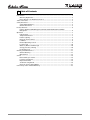
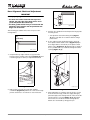
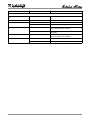
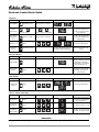
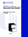
ULIN_016357_30092.fm Page 1 Thursday, March 23, 2006 2:58 PM
Use and Care Guide
Combo® Ice Maker/Refrigerator Model:
CO2175FF
Refrigerator/Freezer Model:
2175RF
CO2175FF
2175RF
1 Introduction
Congratulations on your purchase of a U-Line refrigeration product. A pioneer in the field for more than 40 years, U-Line
Corporation is the world’s number one manufacturer of built-in, under-counter, specialty refrigeration and ice making
products. U-Line dedicates 100% of its research and development to these products. The result: U-Line technology
consistently leads the market with innovation, design, depth of product line and performance.
U-Line products are making life more convenient in homes, businesses, and hotels around the world. U-Line supports its
products with a strong dealer network, and its commitment to quality even extends to environmentally safe packaging.
IMPORTANT
READ all of the instructions in this guide completely before operating the unit for the first time.
For future reference, keep this guide in a safe, accessible location. If you need additional information or assistance,
please contact U-Line Corporation directly. Contact information appears on the rear cover of this guide.
If you have a problem with the operation of this product, the SERVICE section of this guide will assist you in quickly
identifying common problems and provide information on possible causes and remedies. If your product needs service,
contact U-Line directly.
Warranty Registration
Your U-Line Corporation Limited Warranty is located on the inside rear cover of this guide. To validate your warranty, the
product and its original purchase date must be registered. A Warranty Registration Card has been included for this
purpose in the package containing this manual. Complete and mail the Warranty Registration Card, or register your
product online at www.U-LineService.com as soon as possible after purchase.
If your product registration is not on file and a request for warranty coverage is received, the date of sale to the U-Line
Selling Dealer or Distributor will be established as the first date of warranty coverage for your product.
Please Record Your Model Information
When you request additional information or service, you will be asked for your products model and serial numbers. You
can find this information on the serial plate located on the upper right or rear wall in the interior of your unit. This
information also appears on the warranty registration card.
2
1
ULIN_0023_A
Figure 1
Please record the model number (Figure 1, 1), serial number (Figure 1, 2), date of purchase, and dealer contact
information for your U-Line product below:
Model Number:
Dealer Name:
_____________________________________________________
_____________________________________________________
Serial Number:
Dealer Address:
_____________________________________________________
_____________________________________________________
Purchase Date:
Dealer Telephone:
_____________________________________________________
_____________________________________________________
2
CO2175FF, 2175RF
2 Table of Contents
Introduction ...............................................................................................................................2
Warranty Registration .......................................................................................................2
Please Record Your Model Information ...........................................................................2
Table of Contents .......................................................................................................................3
Safety Precautions ......................................................................................................................5
Safety Alert Definitions .....................................................................................................5
General Precautions ...........................................................................................................5
Product Features ........................................................................................................................6
Échelon Model 2175RF Refrigerator/Freezer, Model CO2175FF Ice Maker/
Refrigerator ........................................................................................................................6
Operation ...................................................................................................................................7
Initial Startup .....................................................................................................................7
Temperature Control .........................................................................................................7
Interior Lighting .................................................................................................................8
Electronic Control Panel ....................................................................................................8
Ice Maker ............................................................................................................................9
Normal Operating Sounds .................................................................................................9
Food Storage ....................................................................................................................10
Outdoor, Marine and RV Usage ......................................................................................10
Storage, Vacation, Moving ..............................................................................................10
Product Disposal ...............................................................................................................11
Cleaning and Maintenance .....................................................................................................11
General Cleaning .............................................................................................................11
Maintenance ....................................................................................................................12
Service .......................................................................................................................................18
Before Calling for Service ................................................................................................18
If Service is Required ........................................................................................................18
Replacement Parts ...........................................................................................................18
Troubleshooting Guide ....................................................................................................19
Electronic Control Quick Guide .......................................................................................21
U-Line Corporation Limited Warranty ....................................................................................23
CO2175FF, 2175RF
3
This page intentionally left blank
4
CO2175FF, 2175RF
WARNING
3 Safety Precautions
IMPORTANT
PLEASE READ all instructions completely before
attempting to install, operate, or service your unit.
• Proper installation procedures must be followed
if this unit is being initially installed, or is moved
to a new location after being in service. An
INSTALLATION GUIDE for your unit, providing
complete installation information is available
from U-Line Corporation directly, and must be
consulted before any installation is begun. U-Line
contact information appears on the rear cover of
this guide.
• This unit requires connection to a grounded
(three-prong), polarized receptacle that has been
placed by a qualified electrician in accordance
with applicable electrical codes.
Safety Alert Definitions
Safety items throughout this guide are labeled with a
Danger, Warning or Caution based on the risk type:
DANGER
Danger means that failure to follow this safety
statement will result in severe personal injury or
death.
WARNING
Warning means that failure to follow this safety
statement could result in serious personal injury
or death.
CAUTION
Caution means that failure to follow this safety
statement may result in minor or moderate
personal injury, property or equipment damage.
General Precautions
Use this appliance for its intended purpose only and
follow these general precautions along with those listed
throughout this guide:
SHOCK HAZARD - Electrical Grounding Required.
• Never attempt to repair or perform
maintenance on the unit until the electricity
has been disconnected.
• Never remove the round grounding prong from
the plug and never use a two-prong grounding
adapter.
• Altering, cutting of power cord, removal of
power cord, removal of power plug, or direct
wiring can cause serious injury, fire and/or loss
of property and/or life, and will void the
warranty.
• Never use an extension cord to connect power
to the unit.
• Always keep your working area dry.
CAUTION
• Use care when moving and handling the unit. Use
gloves to prevent personal injury from sharp
edges.
• If your model requires defrosting, DO NOT use any
type of heater to defrost. Using a heater to speed
up defrosting can cause personal injury and
damage to the inner lining.
IMPORTANT
• Do not lift unit by door handle.
• Never install or operate the unit behind closed
doors. Be sure front grille is free of obstruction.
Obstructing free air flow can cause the unit to
malfunction and may void the warranty.
• Failure to clean the condenser every three months
can cause the unit to malfunction. This could void
the warranty.
• Allow unit temperature to stabilize for 24 hours
before use.
• If your model requires defrosting, never use an
ice pick or other sharp instrument to help speed
up defrosting. These instruments can puncture
the inner lining or damage the cooling unit.
• Use only genuine U-Line replacement parts.
Imitation parts can damage the unit, affect its
operation or performance and may void the
warranty.
DANGER
RISK OF CHILD ENTRAPMENT. Before you throw away
your old refrigerator or freezer, take off the doors
and leave shelves in place so that children may not
easily climb inside.
CO2175FF, 2175RF
5
• Self-closing door hinges engage when the door is open
approximately 8-10 in. (20-25 cm), ensuring a positive
door seal and preventing door bounce back.
4 Product Features
Échelon Model 2175RF Refrigerator/
Freezer, Model CO2175FF Ice Maker/
Refrigerator
Exclusive Features of Échelon
• Both models feature Frost Free technology and a 5.7 cu
ft (161 L) capacity.
• An electronic control panel with digital display allows
you to display the interior temperature and adjust the
setting to your preference. The electronic control and
digital display provide an attractive appearance, and its
method of control provides precise temperature
settings.
• An interior light will illuminate automatically as the
cabinet door is opened. However, you can easily select
another mode of operation. A blackout/Sabbath mode
(not Star K certified) allows you to darken both interior
light and the LED display, while maintaining complete
temperature control in the unit for 36 hours.
• A new condenser design optimizes product
performance and energy efficiency while providing
further reductions in noise levels.
• Black and white models feature a slightly contoured,
across the top, integrated door handle design that
permits the door to be easily reversed. The doors come
standard with a factory installed flush panel. They can
accommodate a 1/4 in. (0.64 cm) thick custom panel to
achieve a custom, built-in look by matching
surrounding cabinets.
• An optional full overlay door panel kit for black and
white units, using a customer provided 3/4 in. (1.9 cm)
thick panel, is available that provides a fully integrated
appearance with surrounding cabinets. The overlay
panel is easily attached to the door.
• Black and white models feature a vinyl clad steel
cabinet that provides a rich textured look, and resists
scratching, peeling and flaking.
• All stainless steel models have a full wrap stainless steel
cabinet, stainless steel hinges, and a full wrap stainless
steel door with sculpted stainless steel handle.
• Stainless steel models are suitable for outdoor use by
UL.
Features and specifications are subject to change without
notice.
• A new evaporator and improved refrigeration system
design provide freezer temperatures between -5 and
+5°F, and consistent temperature control in the
refrigerator.
• Model 2175RF features a large vertically designed
freezer compartment that provides more storage space
and easier accessibility to the products within the
freezer compartment. A removable white vinyl coated
wire shelf can divide the compartment in half, allowing
products to be placed underneath and on top of the
shelf for more organized storage.
• Model CO2175FF features an ice maker with a daily
production capacity of 8 lbs (3.6 kg), and storage for 13
lbs (5.9 kg).
• Three fully encapsulated, contoured shelves contain
spills and are easy to clean.
• Recessed shelf channels, supporting the encapsulated
shelves, provides a sleek, clean appearance to the
interior of the cabinet by eliminating protruding shelf
supports.
• A removable, clear lower crisper drawer optimizes the
organization of product stored in the crisper. The
crisper may also be used to transport its contents to a
cooking or serving area.
• Two contoured inner door "pick-off" shelves are
adjustable for storage of a variety of different bottle,
can, and container sizes and shapes.
• The lower inner door shelf accommodates a two liter
or 750 mL bottle.
6
CO2175FF, 2175RF
Temperature Control
5 Operation
Checking Product Temperature
ULIN_0080_A
Figure 2
IMPORTANT
Proper air flow (Figure 2) is required for your unit to
operate at its highest efficiently. A grille, located in
the base of the unit, must not be blocked at any
time, or your unit will not perform as expected.
ULIN_0093_A
Initial Startup
All U-Line units are shipped with controls that are preset.
No initial adjustments are required.
IMPORTANT
• U-Line recommends the unit be allowed to run
overnight prior to loading the unit with product.
• On ice maker equipped units, it is possible that
dirt or scale will dislodge in the water line.
Always throw away all ice cubes made during the
first two to three hours of operation.
1
2
3
4
Figure 4
To check the actual product temperature, in refrigerator
section only, insert an accurate thermometer into a plastic
(non-breakable) bottle that is partially filled with water.
Tighten the bottle cap securely (Figure 4).
Place the bottle in the refrigerator area for 24 hours.
Refrain from opening the unit during the testing period.
After 24 hours, check the temperature of the water. If
required, adjust the temperature control in a small
increment (See ADJUSTING TEMPERATURE).
Factors which affect the internal temperatures of the
cabinet include:
5
• Temperature setting.
• Ambient temperature where installed.
• Number of times and length of time the door is
opened and closed.
ULIN_0058_A
Figure 3
• Installation in direct sunlight or near a heat source.
To turn the unit on or off, touch and hold the POWER icon
(Figure 3, 1) on the display panel for approximately ten
seconds until the °F symbol flashes and release.
• A small LED above the icon will illuminate to confirm
the touch of any controller icon.
• The display (Figure 3, 3) will show the unit set-point
temperature (38°F) when the unit is on and will show
OFF when the unit is off.
• Turning the unit off will override any other control
function.
CO2175FF, 2175RF
7
Interior Lighting
Temperature Display
The LIGHT icon (Figure 3, 5) on the control panel is used
to control an additional lighting function. The blackout/
Sabbath mode (not Star K certified) will turn the interior
light and display (Figure 3, 3) off.
To display the interior temperature:
To access the blackout/Sabbath mode (not Star K
certified):
2. The display (Figure 5, 3) will indicate the actual
refrigerator temperature.
1. Touch and hold the LIGHT icon (Figure 3, 5) for ten
seconds and release (the °F symbol will flash briefly at
the end of the five second period).
3. After approximately 10 seconds, the set-point
temperature will return to the display.
2. The interior light and control display (Figure 3, 3) will
go dark for 36 hours.
NOTE: Although the display will not be visible, the
temperature controls in the unit remain active, and the
interior temperature will be maintained.
3. To exit the blackout/Sabbath mode (not Star K
certified) before the 36-hour time period, repeat Step
1.
Electronic Control Panel
1
2
3
4
1. Touch and hold the WARMER icon (Figure 5, 2) for
approximately five seconds and release when the °F
symbol in the display (Figure 5, 3) begins to flash.
Factors which affect the internal temperatures of the
cabinet include:
• Temperature setting.
• Ambient temperature where installed.
• Number of times and length of time the door is
opened and closed.
• Installation in direct sunlight or near a heat source.
Adjusting Temperature
NOTE: Refrigerator section temperatures are adjustable.
Freezer temperatures are not adjustable.
5
IMPORTANT
Adjust the set-point temperature in single
increments, and wait 24 hours for the temperature
to stabilize before rechecking.
ULIN_0058_A
1
Figure 5
The electronic control with digital display (Figure 5) is
configured to show a single temperature continuously.
This set-point temperature is a base number used by the
controller to maintain the temperature zone in your unit.
The factory default set-point is 38°F. This set-point
temperature is used as a gauge if further temperature
adjustments are required.
2
3
4
5
ULIN_0058_A
Figure 6
To adjust the set-point temperature:
Temperature Display Selection
U-Line products supplied for 110 VAC operation have
temperatures displayed in a default Fahrenheit (°F)
configuration (Figure 5, 3). Models supplied for 220 VAC
operation have temperatures displayed in a default
Celsius (°C) configuration.
The display can easily be adjusted for either type of
temperature display. Press and hold the LIGHT icon
(Figure 5, 5) and within five seconds press the COOLER
icon (Figure 5, 4) three times to change the display as
desired.
1. Press and release either the WARMER (Figure 6, 2) or
COOLER (Figure 6, 4) icon to put the controller in the
SET TEMPERATURE mode. The °F symbol (Figure 6, 3)
will begin to flash.
NOTE: If no further action is taken, this mode will self
cancel in five seconds, and the original set-point
temperature will be displayed.
2. While the °F symbol is flashing, press the WARMER or
COOLER icon as required to adjust the set-point
temperature.
3. The change will be set five seconds after adjusting the
temperature and the new set-point temperature will be
displayed.
8
CO2175FF, 2175RF
Ice Maker
When the ice bucket is full, the ice making mechanism will
shut off. However, the refrigeration system will continue
to cool and maintain the cube supply. Frost-free icemaker
units have lower ice production than manual defrost
units.
IMPORTANT
Do not place cans or bottles in the ice compartment
because they will freeze.
The ice bucket can be removed for emptying and
cleaning. To remove the ice bucket, raise the bin arm and
remove the bucket from the ice compartment. Use the ice
bucket for ice storage only.
Normal Operating Sounds
All models incorporate rigid foam insulated cabinets to
provide high thermal efficiency and maximum sound
reduction for its internal working components. In spite of
this technology, your model may make sounds that are
unfamiliar.
Normal operating sounds may be more noticeable
because of the unit’s environment. Hard surfaces such as
cabinets, wood/vinyl/tiled floors and paneled walls have a
tendency to reflect normal appliance operating noises.
Common refrigeration components, and a brief
description of the normal operating sounds they make,
are listed below. NOTE: Your product may not contain all
of the components listed.
• Compressor: The compressor makes a hum or pulsing
sound that may be heard when it operates.
• Evaporator: Refrigerant flowing through an evaporator
may sound like boiling liquid.
ULIN_0087_A
Figure 7
Ice production may be interrupted by raising the bin arm
into an upright and locked position (Figure 7). The unit
will maintain temperature for ice storage.
IMPORTANT
If you are not intending to use the ice maker and
turn the supply valve off, it is imperative to raise
the bin arm of the ice maker (Figure 7). Failure to
raise the bin arm may result in damage to the water
valve.
• Condenser Fan: Air moving through a condenser may be
heard.
• Automatic Defrost/Drain Pan: Water may be heard
dripping or running into the drain pan when the unit is in
the defrost cycle.
• Automatic Ice Maker: You will hear ice as it drops from
the mold into the ice bin/tray.
• Water Valve: After an ice maker completes a cycle, a water
valve will make a buzzing sound and running water may
be briefly heard.
Certain sounds are normal during the unit’s operation.
You may hear the compressor or fan motor, the water
valve, or ice dropping into the ice bucket.
WARNING
NEVER use an ice pick, knife or other sharp
instrument to separate cubes. Shake the ice
bucket instead.
During periods of limited usage or high ambient
temperatures, it is common for cubes to fuse together.
Shake the bucket to break apart cubes. If the ice maker is
not used regularly, the ice bucket should be emptied
periodically to ensure fresh cubes.
It is normal for cubes to appear cloudy. This is caused by
air being trapped in the water due to fast freezing. It has
nothing to do with the health, taste or chemical make-up
of the water. It is the same air that is in every glass of
water you drink.
CO2175FF, 2175RF
9
Food Storage
Storage, Vacation, Moving
Crisper
If the unit will not be used for an extended period, or
otherwise stored, follow these steps completely:
Your models may have a lower crisper drawer for storage.
WARNING
Electrical Shock Hazard. Disconnect power before
servicing. Before operating, replace all panels.
Failure to do so may result in death or electrical
shock.
1. Remove all consumable contents from the unit.
2. Disconnect power to the unit.
3. Shut off water supply to the unit at the main water
source.
IMPORTANT
ULIN_0114_A
Figure 8
To open, grasp the crisper handle (Figure 8) and slowly
pull out to access the drawer contents. The crisper may be
completely removed for cleaning.
IMPORTANT
If the drawer is pulled out too far, it will come out
of the cabinet, and may be damaged by falling.
• If the ambient temperature is expected to drop
below 45°F, turn off and unplug unit, and drain all
water from the unit to prevent freezing damage
not covered by the warranty.
• The use of anti-freeze or other products of this
nature is not necessary and is not recommended.
4. Disconnect the water valve inlet and outlet lines, and
allow them to drain completely.
Outdoor, Marine and RV Usage
5. Reconnect power to the unit, and allow it to run for
one hour (minimum) until any remaining ice has been
ejected from the ice maker assembly.
Some U-Line models are designed to operate in outdoor,
marine and RV environments. For best performance, keep
the unit out of direct sunlight.
6. Disconnect power to the unit, dry any remaining water
from the ice maker assembly, and reconnect any lines
removed from the water supply valve.
• If the unit will be shut off for five days or more, prop
door open to allow for air circulation and prevent mold
and mildew.
7. Disconnect the power cord from its outlet, and leave it
disconnected until the unit is returned to service.
IMPORTANT
If the ambient temperature is expected to drop
below 45°F, turn off and unplug unit, and drain all
water from the unit to prevent freezing damage not
covered by the warranty.
8. Clean and dry the interior of the cabinet (See CLEANING
AND MAINTENANCE: GENERAL CLEANING).
9. During periods of non-use, the cabinet must remain
open to prevent the formation of mold and mildew.
Open door a minimum of 2" (5 cm) to provide the
necessary ventilation.
• High ambient temperatures (110°F or higher) may
reduce the unit's ability to reach low temperatures.
10
CO2175FF, 2175RF
Product Disposal
6 Cleaning and Maintenance
If the unit is being removed from service for disposal,
check and obey all Federal, State and/or Local regulations
regarding the disposal and recycling of refrigeration
appliances, and follow these steps completely:
General Cleaning
1. Disconnect power to the unit and unplug the power
cord from its outlet.
Black and White Models:
2. Shut off water supply to the unit at the main water
source and disconnect the supply line to the unit’s water
valve.
DANGER
Exterior Cleaning (As Required)
• Surfaces may be cleaned with a mild detergent and
warm water solution. Do not use solvent-based or
abrasive cleaners. Use a soft sponge and rinse with
clean water. Wipe with a soft, clean towel to prevent
water spotting.
Stainless Steel Models:
RISK OF CHILD ENTRAPEMENT. Before you throw
away your old refrigerator or freezer, take off the
doors and leave shelves in place so that children
may not easily climb inside.
3. Remove the cabinet door if equipped and secure all
interior shelves to the interior of the cabinet using a
heavy duty cloth or package sealing tape.
• Stainless steel surfaces and components can discolor
when exposed to chlorine gas, pool chemicals, salt
water or cleaners with bleach.
• Keep your stainless steel unit looking new by cleaning
with a good quality all-in-one stainless steel cleaner/
polish on a monthly basis. For best results use Claire®
Stainless Steel Polish and Cleaner, which can be
purchased from U-Line Corporation (P/N 173348).
Comparable products are acceptable. Frequent
cleaning will remove surface contamination that could
lead to rust. Some installations may require cleaning
on a weekly basis.
• Do not clean with steel wool pads.
• Do not use cleaners that are not specifically
intended for stainless steel on stainless steel
surfaces (this includes glass, tile and counter
cleaners).
• If any surface discoloring or rusting appears, clean it
quickly with Bon-Ami® or Barkeepers Friend Cleanser®
and a non-abrasive cloth. Always clean in the direction
of the grain. Always finish this process with Claire
Stainless Steel Polish and Cleaner or comparable
product to prevent further problems.
• Using abrasive pads such as Scotchbrite™ will
cause the graining in the stainless steel to
become blurred.
• Rust that is not cleaned up promptly can penetrate into
the surface of the stainless steel and complete removal
of the rust may not be possible.
Interior Cleaning (As Required)
• Disconnect power to the unit. Clean the interior and all
removed components using a mild non-abrasive
detergent and warm water solution applied with a soft
sponge or non-abrasive cloth. Rinse the interior using a
soft sponge and clean water.
• Do not use any solvent-based or abrasive
cleaners. These types of cleaners may transmit
taste to the interior products and damage or
discolor the interior.
CO2175FF, 2175RF
11
Maintenance
CAUTION
Proper maintenance of your U-Line product will ensure
efficiency, top performance and long life. The
maintenance intervals listed are based on normal
conditions. You may want to shorten the intervals if you
have pets or other special considerations.
Defrosting
DO NOT use any type of cleaner on the condenser
unit.
4. Clean the condenser coil (Figure 9, 2) using a soft
brush with a “combing” action or vacuum cleaner. Do
not touch the condenser coil.
5. Position the grille to align the mounting screws with
the holes in the cabinet.
Frost-Free Models
Frost-free models do not produce frost in normal
operating conditions.
6. Secure, but do not over-tighten both grille screws.
7. Reconnect power to the unit.
WARNING
Ice Maker Maintenance
DO NOT use any type of electrical heating device,
ice pick, knife or other sharp instrument to
defrost; this could damage the inner lining or
refrigeration system and void the warranty.
Condenser Cleaning
Interval - Every Three Months
To maintain operational efficiency, keep the front grille
free of dust and lint and clean the condenser every three
months. Depending on environmental conditions, more
or less frequent cleaning may be necessary.
Inlet Screen
Interval - Every Twelve Months
The solenoid valve inlet screen must be cleaned at least
once each year as follows:
1. Shut off the water at the main supply valve.
2. Pull the unit out to access the back panel.
3. Disconnect electrical power to the unit.
2
WARNING
Disconnect electric power to the unit before
cleaning the condenser.
To remove and replace the grille for access to the
condenser fins, follow this procedure:
1
1
ULIN_0054_A
Figure 10
4. Disconnect the hose connector (Figure 10, 1) from the
water solenoid valve (Figure 10, 2).
2
5. DO NOT remove the inlet screen from the water
solenoid valve. Use a tooth brush to gently clean any
sediment from the inlet screen.
ULIN_0203_A
Figure 9
1. Disconnect electrical power to the unit.
2. Loosen two screws (Figure 9, 1) completely.
NOTE: Screws are held in the grille by o-ring retainers,
and will not come free of the grille.
3. Remove the grille.
6. Re-connect the water supply hose connector (Figure
10, 1) to the water solenoid valve (Figure 10, 2).
Tighten the connector securely.
7. Open the water main supply valve and check for
leakage at the water hose connection. Ensure that the
water supply line is not kinked.
8. Reconnect power to the unit before re-installing.
WARNING
DO NOT touch the condenser fins. The condenser
fins are SHARP and can be easily damaged.
12
CO2175FF, 2175RF
Ice Cube Thickness Adjustment
4. Install the ice maker assembly cover.
Interval - As Required
On ice maker equipped models, the cube size may be
adjusted by changing the amount of water injected into
the ice maker assembly as follows:
IMPORTANT
Use only genuine U-Line replacement parts. U-Line
ice maker parts are not the same as standard FSP
Whirlpool parts. Using non U-Line parts can reduce
ice rate, cause water to overflow from ice maker
mold, damage the unit, and may void the warranty.
Leveling
It is important that units equipped with adjustable feet
are level, for proper door and ice maker (if equipped)
operation.
To level units with adjustable feet:
ULIN_0273_A
Figure 11
1
1. Remove the ice maker assembly cover (Figure 11).
ULIN_0193_A
Figure 13
1. Use a level to check the levelness of the unit from
front to back and from side to side. Level should be
placed along top edge and side edge as shown
(Figure 13).
ULIN_0056_A
Figure 12
2. Locate the adjusting screw on the ice maker assembly
control box. The adjusting screw is just below the minus
(-) and plus (+) signs on the control box (Figure 12).
NOTE: Make adjustments in small increments. Too
large of an adjustment could cause the unit to
malfunction.
1
ULIN_0042_A
Figure 14
2. If the unit is not level, adjust the feet on the corners of
the unit as necessary (Figure 14).
3. Check the levelness after each adjustment and repeat
the previous steps until the unit is level.
CAUTION
Too large of an adjustment to the screw can cause
the water to overflow the ice maker and can cause
property damage.
3. Turn the adjusting screw toward the minus (-) sign
(clockwise) for smaller cubes or toward the plus (+) sign
(counterclockwise) for larger cubes.
CO2175FF, 2175RF
13
Door Alignment Check and Adjustment
IMPORTANT
When properly aligned:
1
• The door will not be flush with the top of the
cabinet. The top edge of the door will be 1/8 in.
(3.175 mm) below the cabinet top.
• The door gasket will be firmly in contact with the
perimeter of the cabinet and not pinched on the
hinge side of the door.
The following procedure will correct for up to 1/4 in.
misalignment:
2
3
ULIN_0201_A
Figure 17
3. Turn the door upside down and inspect the hinge plate
mounting holes.
• Your plate has slotted mounting holes (Figure
17, 1). Loosen but do not remove the two hinge
plate screws.
1/8"
(3.175 mm)
4. If door edge opposite the hinges needs to move up,
move plate toward outside of door (Figure 17, 2). If
door edge needs to move down, move plate toward
inside of door (Figure 17, 3). Repeat until top edge of
door is parallel with top of cabinet and tighten screws
securely (Figure 17, 1).
ULIN_0016_A
Figure 15
1. Compare the top edge of the door (opposite the
hinges) to the top edge of the cabinet (Figure 15) and
note the type (up or down) of adjustment needed.
ULIN_0133_A
1
Figure 16
ULIN_0004_A
2. Remove the top hinge pivot pin with a Phillips
screwdriver (Figure 16) and lift door off bottom hinge
pin. Be careful not to lose the door closer insert sets.
14
Figure 18
5. After adjustment is complete, remove the door closers
from the bottom hinge, clean thoroughly and apply
petroleum jelly to the mating surfaces of the closers. Be
sure that bosses on closers (Figure 18, 1) align with
holes in the door and bottom cabinet hinge plates.
Mount door and install top hinge pivot pin.
CO2175FF, 2175RF
Door Reversal
1
ULIN_0002_A
Figure 21
2. Remove plastic screw plugs (three each, top and
bottom) (Figure 21, 1) from new hinge location. Do
not discard.
3. Remove top hinge (three screws) (Figure 20, 2) and
reinstall hinge screw pin (Figure 20, 1).
ULIN_0015_A
Figure 19
Black and white units may be left- or right-hand opening.
Stainless steel unit doors cannot be reversed. The doors
are easily reversed by moving the hinge hardware to the
opposite side. The top hinge hardware will be used on the
bottom of the other side and the bottom hinge hardware
will be used on the top of the other side (Figure 19).
1
ULIN_0005_A
To reverse the door:
Figure 22
4. Install the removed top hinge mount on opposite side
BOTTOM (Figure 22).
1
2
ULIN_0003_A
Figure 20
1. Remove top hinge screw pin (Figure 20, 1) from door
using a Phillips screwdriver. Remove door by tilting
forward and lifting off bottom hinge pin.
1
ULIN_0004_A
Figure 23
CO2175FF, 2175RF
15
5. Remove the two door closer inserts (Figure 23, 1) from
the existing bottom hinge and install as shown on the
new bottom hinge (Figure 22, 1).
Door Shelf Removal/Insertion
6. Remove existing bottom hinge (three screws) and
remount on opposite side TOP. Remove hinge screw pin.
1
7. Remove the plastic hole plug from the top of the door
to allow the pivot pin to be inserted in the new
location. Install the plug into the vacated hole on the
opposite side.
2
ULIN_0006_A
ULIN_0039_A
Figure 24
Figure 25
8. With bottom of door facing up, remove pivot plate
(two screws), flip over, and remount on opposite side of
door (Figure 24). Be sure notch in plate faces
center.
To remove the door shelf:
9. Holding door upright with top of door tilted forward,
place hole of door pivot plate on bottom hinge screw
pin/closer inserts (Figure 22, 1).
To install the door shelf:
10. Tilt top of door into position in top hinge and install top
hinge screw pin.
11. Install plastic screw plugs removed in Step 2 in old hinge
holes (three each, top and bottom).
16
1. Grasp shelf in center, lift slightly, and tilt 15°-20°.
2. Carefully pull shelf off bosses (Figure 25, 2).
1. Holding shelf in center, align notches (Figure 25, 1) in
shelf with bosses (Figure 25, 2) in door.
2. Tilt shelf at a 15°-20° angle and slide onto bosses at the
desired location.
CO2175FF, 2175RF
Glass Shelf Removal/Installation
Light Bulb Replacement
Remove the shelves as follows:
To replace the light bulb in your U-Line unit:
1
2
ULIN_0001_A
Figure 27
1. Grasp the edges of the light housing lens
(Figure 27, 1) opposite the exposed tab and gently
push the lens toward the tab (Figure 27, 2).
2. Pull the edge of the lens down (Figure 27, 1) and
swing it out of the light housing.
IMPORTANT
ULIN_0213_A
Figure 26
1. Pull shelf out about 6" (Figure 26) until back of shelf
clears the “hump” on the right hand side.
2. Tilt right hand edge of shelf up.
ALWAYS use a genuine U-Line replacement bulb (P/N
31317) in the light housing. Use of any other bulb
within the housing will generate excessive heat,
causing damage to the light housing and cabinet
interior, and will compromise the precise
temperature control of your unit.
3. Replace the bulb only with a genuine U-Line P/N 31317
replacement.
3. Remove shelf from unit by pulling out.
Insert the shelves as follows:
1. Insert shelf at an angle, approximately 15-20°, over the
rib in the side of the unit where you want to place the
shelf. The shelf must be started into the unit at an
angle to clear the door.
4. Replace the lens by first inserting the tab side back into
the housing at a slight angle. While gently pushing the
lens towards the tab end, push the free end up into the
housing, and release when you will hear a snap/click.
2. Continue to slide the shelf into the unit at an angle
until it clears the door.
3. Lower the shelf and push it in completely.
CO2175FF, 2175RF
17
7 Service
Before Calling for Service
If your U-Line product appears to be malfunctioning, read
through the OPERATION section of this guide to ensure
that the function of all controls are clearly understood. If
the malfunction persists, the TROUBLESHOOTING GUIDE
in this guide will assist you in quickly identifying common
problems, and provide information on possible causes and
remedies. Most often, this will resolve the problem
without the need to call for service.
If Service is Required
If you do not understand a troubleshooting remedy, or
your product needs service, contact U-Line Corporation
directly. Contact information appears on the rear cover of
this guide.
You will be asked for your product Model and Serial
Numbers. This information should be recorded inside the
front cover of this guide, following the products original
purchase. It also appears on the Model and Serial number
plate located on the upper right or rear wall of the
interior of your product.
Replacement Parts
When you need replacement parts, always request that
genuine U-Line replacements be used. U-Line products
have been designed and engineered using components
that work efficiently, and provide superior service life and
performance. The use of aftermarket parts or components
may affect the safety, operation, performance or
durability of your product, and may also void its warranty.
18
CO2175FF, 2175RF
Troubleshooting Guide
DANGER
ELECTROCUTION HAZARD
Never attempt to repair or perform maintenance on
the unit until the main electrical power has been
disconnected.
Troubleshooting - What to check when problems occur:
PROBLEM
POSSIBLE CAUSE
REMEDY
Unit does not operate and
electronic display is blank.
No electrical supply
Plug unit in or check circuit breaker.
No interior light
Loose or burned out bulb
Tighten or replace bulb (See MAINTENANCE; LIGHT
BULB REPLACEMENT).
Electronic display is blank and
Unit is in blackout/Sabbath mode
interior light is OFF with door OPEN. (not Star K certified) lighting mode.
Exit blackout/Sabbath mode (not Star K certified)
(See OPERATION; INTERIOR LIGHT CONTROL).
Electronic display is blank and
interior light is ON with door OPEN.
A display function has changed.
Touch and hold the warmer temperature button and
touch and release the POWER button three times, then
release the temperature button. The display should
become visible.
Electronic display shows repeating,
randomly flashing symbols and
partial characters.
A factory control mode has been
inadvertently entered.
Touch and hold the warmer temperature button and
touch and release the LIGHT button three times, then
release the temperature button to exit the factory
control mode. The set-point temperature should now
be displayed.
Electronic display shows:
0, 1 to 26, or 99.
A factory control mode has been
inadvertently entered.
Repeatedly touch the warmer temperature button to
advance any number shown to 99 and touch and
release the LIGHT button. The set-point temperature
should now be displayed.
Electronic display shows E3.
Door has been left open longer than
20 minutes.
Close door completely. The set-point temperature
should now be displayed.
Electronic display shows one or
more of the following:
E1, E2, E4, E5, E6, E7, E8, E9, E10, P1.
The unit is displaying an error code.
Record the error code(s) displayed and call for service.
Unit not cold enough. Check
temperatures (See OPERATION for
approximate temperatures).
Control set too warm
Set control to a cooler setting (See OPERATION). Allow
24 hours for temperature to stabilize.
Airflow to front grille blocked
Airflow must not be obstructed to front grille (See
OPERATION).
Dirty condenser coils
Clean condenser (See MAINTENANCE; CONDENSER
CLEANING).
Door gasket not sealing properly
Door adjustment required (See MAINTENANCE; DOOR
ALIGNMENT CHECK AND ADJUSTMENT).
Unit is too cold. Check temperatures
(See OPERATION for approximate
temperatures)
Control set too cold
Set control to a warmer setting (See OPERATION). Allow
24 hours for temperature to stabilize.
Noise during operation
Copper water supply tubing
contacting internal components
Carefully bend tubing away from cabinet and
components.
Certain sounds are normal.
Soft sounds from the fan and water/dropping sounds
from the ice maker will be heard.
Temperature control set too cold
Set control to warmer setting (See OPERATION).
Inaccurate temperature reading
Properly check temperature (See OPERATION).
Refrigerator too cold
CO2175FF, 2175RF
19
PROBLEM
POSSIBLE CAUSE
REMEDY
ICE MAKER EQUIPPED MODELS ONLY
Water is leaking out the back of the
unit.
Water supply connection leaking
Tighten fitting as required.
Ice cubes sticking together
Infrequent use of cubes
Break apart cubes.
No ice
Bin arm locked in upright position
Lower bin arm.
No water to unit
Turn on water or contact plumber.
Ice cube size too large
Set cube size smaller (See MAINTENANCE; ICE MAKER;
ICE CUBE THICKNESS ADJUSTMENT).
Dirty condenser coils
Clean condenser (See MAINTENANCE; CONDENSER
CLEANING).
Water leaks into ice bucket.
Water level set too high
Set cube size smaller (See MAINTENANCE; ICE MAKER;
ICE CUBE THICKNESS ADJUSTMENT).
Refrigerator too cold
Ice bucket not fully inserted
Push ice bucket into place.
Freezer door not closed correctly
Be sure freezer door is closed correctly.
Not enough ice
20
CO2175FF, 2175RF
Electronic Control Quick Guide
All Models
Task
Touch
Turn ON/OFF
Adjust
Temperature
Hold 10 seconds
Touch
Display
Release when °F flashes.
or
or
or
Touch and release
Touch to change temperature
View Actual
Temperature
(T1)
Hold 5 seconds
Change °F-°C
Hold
Blackout
Mode
°F flashes after first touch,
set-point saved after 5
seconds of inactivity and °F
stops flashing.
(For Wine Cooler Only) Will
scroll top/middle/bottom
temperatures.
Release when °F flashes.
Hold 10 seconds
Comment
or
Repeat to switch back.
Display (and cabinet light) not
operable in Blackout Mode.
Blackout will end in 36
hours.
Glass Door Models
Task
Touch
Touch
Display
Cabinet Light
Display Off
Mode
Comment
Light normally goes on/off
with door opening. Pressing
light button will turn
interior light on for 4 hours,
then it will turn off.
Display off when door is
closed (unless cabinet light is
switched on). Repeat to
switch back.
Hold
All Ice Makers
Task
Ice Maker Off
Mode
Touch
Touch
Display
Hold
Comment
Repeat to switch back
Clear Ice & Clear Combo Only
Task
Touch
Touch
Display
Comment
Clean Cycle
Hold
Will automatically return to
ice production when clean
cycle is complete.
Ice Thickness
Adjustment
Hold
Use warmer/colder to scroll.
Temporary
Shutdown
(Office Mode)
Hold
Ice maker will automatically
turn back on in three hours.
NOTE: 38°F is an example; the display will vary with actual set-point.
IMPORTANT
Factory recommended set-point is 38°F for refrigerators and beverage centers, and 50°F for wine coolers.
CO2175FF, 2175RF
21
This page intentionally left blank
22
CO2175FF, 2175RF
U-Line Corporation Limited Warranty
U-Line Corporation warrants each U-Line product to be free from defects in materials and workmanship for a period of
one year from the date of purchase; and warrants the sealed system (consisting of the compressor, the condenser, the
evaporator, the hot gas bypass valve, the dryer and the connecting tubing) in each U-Line product to be free from
defects in materials and workmanship for a period of five years from the date of purchase. During the initial one-year
warranty period for all U-Line products U-Line shall: (1) at U-Lines option, repair any product or replace any part of a
product that breaches this warranty; and (2) for all Marine, RV and Domestic U-Line products sold and serviced in the
United States (including Alaska and Hawaii) and Canada, U-Line shall cover the labor costs incurred in connection with
the replacement of any defective part. During years two through five of the warranty period for the sealed system, ULine shall: (1) repair or replace any part of the sealed system that breaches this warranty; and (2) for all Marine, RV and
Domestic U-Line products sold and serviced in the United States (including Alaska and Hawaii) and Canada, U-Line shall
cover the labor costs incurred in connection with the replacement of any defective part of the sealed system. All other
charges, including transportation charges for replacements under this warranty and labor costs not specifically covered
by this warranty, shall be borne by you. This warranty is extended only to the original purchaser of the U-Line product.
The Registration Card included with the product should be promptly completed by you and mailed back to U-Line or you
can register on-line at www.U-LineService.com.
The following are excluded from this limited warranty: installation charges; damages caused by disasters or acts of God,
such as fire, floods, wind and lightening; damages incurred or resulting from shipping, improper installation,
unauthorized modification, or misuse/abuse of the product; customer education calls; food loss/spoilage; door and water
level adjustments (except during the first 90 days from the date of purchase); defrosting the product; adjusting the
controls; door reversal; or cleaning the condenser.
If a product defect is discovered during the applicable warranty period, you must promptly notify either the dealer from
whom you purchased the product or U-Line at P.O. Box 245040, Milwaukee, Wisconsin 53224 or at 414-354-0300. In no
event shall such notification be received later than 30 days after the expiration of the applicable warranty period. U-Line
may require that defective parts be returned, at your expense, to U-Lines factory in Milwaukee, Wisconsin, for
inspection. Any action by you for breach of warranty must be commenced within one year after the expiration of the
applicable warranty period.
This limited warranty is in lieu of any other warranty, express or implied, including, but not limited to any
implied warranty of merchantability or fitness for a particular purpose; provided however, that to the
extent required by law, implied warranties are included but do not extend beyond the duration of the
express warranty first set forth above. U-Lines sole liability and your exclusive remedy under this warranty
is set forth in the initial paragraph above. U-Line shall have no liability whatsoever for any incidental,
consequential or special damages arising from the sale, use or installation of the product or from any other
cause whatsoever, whether based on warranty (express or implied) or otherwise based on contract, tort or
any other theory of liability.
Some states do not allow limitations on how long an implied warranty lasts or the exclusion or limitation of incidental or
consequential damages, so the above limitations may not apply to you. This warranty gives you specific legal rights, and
you may also have other rights which vary from state to state.
CO2175FF, 2175RF
23
F o r G e n e r a l In q u i r i e s :
P.O. Box 245040
Milwaukee, Wisconsin
53224-9540 U.S.A.
Phone (800) 779-2547
FAX (414) 354-5696
www.U-Line.com
For Service and Parts
Assistance:
Phone (800) 779-2547
(414) 354-0300
FAX (414) 354-5696
Email:
[email protected]
www.U-LineService.com
E-mail:
[email protected]
For more than four decades, U-Line has distinguished itself as the
leader in built-in under-counter ice making, refrigeration and
wine storage appliances.
An INSTALLATION MANUAL for your unit, providing complete
installation information, is available for download at
www.U-Line.com. Information for custom panel inserts per model,
including panel size, and instructions are available by visiting
www.U-Line.com.
When you need replacement parts, always request genuine U-Line
replacements be used. Visit www.U-Line.com to locate a parts
distributor in your area.
U-Line Corporation, located in Milwaukee, WI, is a family operated manufacturer of built-in
undercounter ice makers, Combo® ice maker/refrigerators, Wine Captain® wine storage units,
refrigerators, refrigerated drawers and refrigerator/freezers.
©2006 U-Line Corporation
Publication No. 30092
01/2006 Rev. A