1
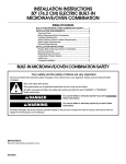
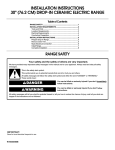
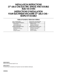
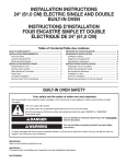
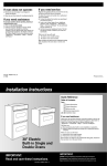
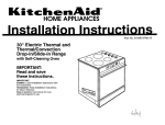
PRECAUTIONS TO AVOID POSSIBLE EXPOSURE TO
EXCESSIVE MICROWAVE ENERGY
(a) Do not attempt to operate this oven with the door open
since open-door operation can result in harmful exposure
to microwave energy. It is important not to defeat or
tamper with the safety interlocks.
(c) Do not operate the oven if it is damaged. It is particularly
important that the oven door close properly and that there
is no damage to the:
(1) Door (bent),
(2) Hinges and latches (broken or loosened),
(3) Door seals and sealing surfaces.
(b) Do not place any object between the oven front face and
the door or allow soil or cleaner residue to accumulate on
sealing surfaces.
(d) The oven should not be adjusted or repaired by anyone
except properly qualified service personnel.
INSTALLATION REQUIREMENTS
Product Dimensions
Tools and Parts
Gather the required tools and parts before starting installation.
27" (68.6 cm) and 30" (76.2 cm) Ovens
Tools needed
■
A
Phillips screwdriver
Parts needed
■
A UL listed or CSA approved conduit connector
■
UL listed wire nuts
Parts supplied
■
2 screws (single oven) or 4 screws (double oven)
B
Check local codes. Check existing electrical supply. See
“Electrical Requirements.”
All electrical connections should be made by a licensed, qualified
electrical installer.
E
Location Requirements
Make sure you have everything needed for correct installation. It is
the responsibility of the installer to comply with the installation
clearances specified in these instructions.
IMPORTANT: Observe all governing codes and ordinances.
Cabinet opening dimensions that are shown must be used. Given
dimensions provide minimum clearance with oven.
■ Recessed installation area must provide complete enclosure
around the recessed portion of the oven.
■
Grounded electrical supply is required. See “Electrical
Requirements” section.
■
Electrical supply junction box should be located 3" (7.6 cm)
maximum below the support surface when the oven is
installed in a wall cabinet. Drill a 1" (2.5 cm) minimum diameter
hole in the right rear or left rear corner of the support surface
to pass the appliance cable through to the junction box.
■
Oven support surface must be solid, level and flush with
bottom of cabinet cutout. Floor must be able to support a total
weight (microwave and built-in oven) of 238 lbs (108 kg).
D
27" (68.6 cm) models
A. 25³⁄₈" (64.5 cm) recessed width
B. 42⁷⁄₁₆" (107.8 cm) overall height
C. 26³⁄₄" (67.9 cm) overall width
D. 23" (58.4 cm) max. recessed
depth
E. 41" (104.1 cm) recessed height
2
C
30" (76.2 cm) models
A. 28³⁄₈" (71.2 cm) recessed width
B. 42⁷⁄₁₆" (107.8 cm) overall height
C. 29³⁄₄" (75.6 cm) overall width
D. 23" (58.4 cm) max. recessed
depth
E. 41" (104.1 cm) recessed height
Installation Clearances
Electrical Requirements
If codes permit and a separate ground wire is used, it is
recommended that a qualified electrical installer determine that
the ground path and wire gauge are in accordance with local
codes.
Do not ground to a gas pipe.
Check with a qualified electrical installer if you are not sure the
oven is properly grounded.
Do not have a fuse in the neutral or ground circuit.
This oven must be connected to a grounded metal, permanent
wiring system.
Be sure that the electrical connection and wire size are adequate
and in conformance with the National Electrical Code, ANSI/NFPA
70-latest edition or CSA Standards C22.1-94, Canadian Electrical
Code, Part 1 and C22.2 No. O-M91-latest edition, and all local
codes and ordinances.
A copy of the above code standards can be obtained from:
27" (68.6 cm) and 30" (76.2 cm) Ovens
A
B
F
D
E
C
27" (68.6 cm) models
A. 27" (68.6 cm) min. cabinet
width
B. 1" (2.5 cm) top of cutout to
bottom of upper cabinet door
C. 19¹⁄₄" (48.9 cm) bottom of
cutout to floor
D. 25¹⁄₂" (64.8 cm) cutout width
E. 1¹⁄₂" (3.8 cm) min. bottom of
cutout to top of cabinet door
F. 41¹⁄₄" (104.8 cm) cutout height
National Fire Protection Association
One Batterymarch Park
Quincy, MA 02269
CSA International
8501 East Pleasant Valley Road
Cleveland, OH 44131-5575
30" (76.2 cm) models
A. 30" (76.2 cm) min. cabinet
width
B. 1" (2.5 cm) top of cutout to
bottom of upper cabinet door
C. 19¹⁄₄" (48.9 cm) bottom of
cutout to floor
D. 28¹⁄₂" (72.4 cm) cutout width
E. 1¹⁄₂" (3.8 cm) min. bottom of
cutout to top of cabinet door
F. 41¹⁄₄" (104.8 cm) cutout height
Electrical Connection
To properly install your oven, you must determine the type of
electrical connection you will be using and follow the instructions
provided for it here.
■ Oven must be connected to the proper electrical voltage and
frequency as specified on the model/serial number rating
plate. (The model/serial number rating plate is located on the
oven door or on the oven frame.)
Cabinet Side View
A
■
Models rated from 7.3 to 9.6 kW at 240 volts (5.5 to 7.2 kW
at 208 volts) require a separate 40-amp circuit. Models rated
at 7.2 kW and below at 240 volts (5.4 kW and below at
208 volts) require a separate 30-amp circuit.
■
A time-delay fuse or circuit breaker is recommended.
■
Connect directly to the fused disconnect (or circuit breaker
box) through flexible, armored or nonmetallic sheathed,
copper cable (with grounding wire). See “Make Electrical
Connection” section.
■
Flexible armored cable from appliance should be connected
directly to the junction box.
■
Do not cut the conduit. Use the length of conduit provided.
■
A UL listed or CSA approved conduit connector must be
provided.
■
If the house has aluminum wiring, connect the aluminum
wiring to the copper wire by using special connectors
designed and UL listed for joining copper to aluminum. Follow
the electrical connector manufacturer’s recommended
procedure. Aluminum/copper connection must conform with
local codes and industry accepted wiring practices.
B
E
D
C
A. 23¹⁄₄" (59.1 cm) min. cutout depth
B. 23" (58.4 cm) recessed oven depth
C. Oven front
D. Recessed oven
E. Cabinet
Cabinet filler kits are available from your dealer. Use matching
color kit if oven is smaller than your cabinet opening.
27" (68.6 cm) oven filler height is 7¹⁵⁄₁₆" (19.8 cm)
Black - 4378950
White - 4378951
Almond - 4378952
30" (76.2 cm) oven filler height is 4¹³⁄₁₆" (12.2 cm)
Black - 4378944
White - 4378945
Almond - 4378946
3
INSTALLATION INSTRUCTIONS
4. Remove bottom screw on each side of the oven trim.
Prepare Oven for Installation
1. Decide on the final location for the oven. Locate existing
wiring to prevent drilling into or severing wiring during
installation.
WARNING
A
Excessive Weight Hazard
Use two or more people to move and install oven.
Failure to do so can result in back or other injury.
2. To prevent floor damage, set the oven onto cardboard prior to
installation. Do not use handle or any portion of the front
frame or trim for lifting.
3. Move oven close to its final location.
4. Remove the shipping materials and tape from the oven.
5. Remove the hardware package from inside the literature bag.
6. Remove and set aside racks and other parts from inside the
oven.
A. Remove trim screw and pull out.
5. Grasp the bottom end of trim and pull away from oven.
6. Slide top end of trim downward to remove trim from oven. Set
trim aside.
Remove Oven Trim
IMPORTANT: Use both hands to remove oven doors.
1. Open the oven door.
2. Locate the oven door latches in both corners of the oven door,
and rotate the latches forward to the unlocked position.
A
Make Electrical Connection
B
WARNING
A. Oven door latch in locked
position
Electrical Shock Hazard
B. Oven door latch in unlocked
position
Disconnect power before servicing.
3. Grasp the edges of the oven door with both hands and close
the oven door until it will no longer close. Lift and pull oven
door toward you and remove. Set the oven door aside on a
protective surface.
Use 8 gauge solid copper wire.
Electrically ground oven.
Failure to follow these instructions can result in death,
fire, or electrical shock.
This oven is manufactured with a neutral (white) power supply
wire and a cabinet-connected bare ground wire crimped together.
1. Disconnect power.
2. Feed the flexible cable conduit from the oven through the
opening in the cabinet.
3. Remove junction box cover if it is present.
4. Connect the flexible cable conduit from the oven to the
junction box using a UL listed or CSA approved conduit
connector.
5. Tighten screws on conduit connector.
4
6. Complete installation following instructions for your type of
electrical connection:
4-wire (recommended)
3-Wire Cable from Power Supply
IMPORTANT: Use the 3-wire cable from power supply where local
codes permit connecting the frame-ground conductor to the
neutral (white) junction box wire:
3-wire (if 4-wire is not available)
Electrical Connection Options
If your home has:
And you will be
connecting to:
Go to section:
4-wire direct
A fused
disconnect or
circuit breaker
box
4-wire Cable from
Power Supply
A fused
disconnect or
circuit breaker
box
3-wire Cable from
Power Supply
5"
(12.7 cm)
3-wire direct
1" m)
c
12.7
(
A
B
C
H
D
E
F
3¹⁄₂"
)
(8.9 cm
I
A. Cable from power supply
B. Junction box
C. Red wires
D. White wire (from power supply)
E. White and green (or bare) oven
ground wires - factory crimped
4-Wire Cable from Power Supply
IMPORTANT: Use the 4-wire cable from power supply where local
codes do not permit connecting the frame-ground conductor to
the neutral (white) junction box wire or when connecting to a
4-wire electrical system.
A
B
G
F. 4-wire cable from oven
G. Black wires
H. UL listed wire nuts
I. UL listed or CSA approved
conduit connector
1. Connect the 2 black wires together using a UL listed wire nut.
2. Connect the 2 red wires together using a UL listed wire nut.
3. Connect the factory crimped white and green (or bare) ground
wires of the oven cable to the white (neutral) wire in the
junction box using a UL listed wire nut.
4. Install junction box cover.
5. Reconnect power.
E
F
G
Install Oven
C
H
D
I
A. Cable from power supply
B. Red wires
C. Green (or bare) ground wires
D. 4-wire cable from oven
E. Junction box
WARNING
Excessive Weight Hazard
Use two or more people to move and install oven.
F. White wires
G. UL listed wire nuts
H. Black wires
I. UL listed or CSA approved
conduit connector
Failure to do so can result in back or other injury.
1. Lift oven into cabinet cutout using the oven opening as an
area to grip.
NOTE: Push against seal area of oven front frame when
pushing oven into cabinet. Do not push against outside
edges.
1. Connect the 2 black wires together using a UL listed wire nut.
2. Connect the 2 red wires together using a UL listed wire nut.
3. Separate the factory crimped green (or bare) and white oven
cable wires.
4. Connect the 2 white wires together using a UL listed wire nut.
5. Connect the green (or bare) ground wire from the oven cable
to the green (or bare) ground wire (in the junction box) using a
UL listed wire nut.
6. Replace junction box cover.
5
2. Push against seal area of front frame to push oven completely
into cabinet and center oven into cabinet cutout.
9. Push hinges in as far as they will go and open the oven door.
You should feel the oven door drop into place.
10. Rotate both hinge latches back to the locked position.
11. Close and open the oven door to check that the door closes
and opens completely. If the oven door does not close or
open completely, repeat the oven door removal process and
reinstall. See “Remove Oven Trim” section.
12. Repeat for lower oven door.
13. Reconnect power.
Complete Installation
3. Securely fasten oven to cabinet using the screws (2 for single
oven, 4 for double oven) provided. Insert the screws through
holes in mounting rails. Do not overtighten screws.
A
1. Check that all parts are now installed. If there is an extra part,
go back through the steps to see which step was skipped.
2. Check that you have all of your tools.
3. Dispose of/recycle all packaging materials.
4. For oven cleaning, read “Oven Care” in the lower oven Use
and Care Guide.
5. Read “Oven Use” in the lower oven Use and Care Guide.
Check Operation of Lower Oven
B
1. Turn power on. “PF” should appear in the display.
2. Press BROIL. “BROIL” will appear in the display.
3. Press START. Make sure the oven door is closed and the
“ON” light is showing in the display area.
If oven(s) does not operate, check the following:
A. Mounting rail
B. Insert screw
4. Slide top end of each trim upward onto oven side rails.
■
Household fuse is intact and tight; or circuit breaker has
not tripped.
■
Electrical supply is connected.
■
See “Troubleshooting” section in the Use and Care Guide.
4. When oven has been on for 2 minutes, feel for heat.
If you do not feel heat or an “F” appears in the display,
turn off the oven and contact a qualified technician.
5. Press LOWER OFF/CANCEL.
6. For the clock setting and other oven functions refer to the Use
and Care Guide.
Check Operation of Microwave Oven
5. Push each trim into place at bottom of trim.
A
1. Fill a microwave-safe container with 1 cup of water and place
container inside microwave oven. Close door firmly.
2. Set microwave oven cook time to “2:00” minutes.
3. Press START. The interior microwave oven light should be on
and the remaining cooking time should be displayed.
When display reads “1:00” minute, open microwave oven
door. The microwave should stop cooking. Close door firmly.
The interior microwave oven light should turn off.
4. Press START. Microwave oven should begin cooking and the
microwave oven interior light should be on.
Let microwave oven complete cooking time. A tone will sound
4 times at the end of the cooking time, and the microwave
oven will shut off.
5. Open microwave oven door and slowly remove container.
Water in container should be hot.
A. Push trim into place and replace screw.
6. Use screws to attach each trim to oven.
7. Replace oven racks.
8. Replace oven door by inserting ends of hinges into hinge slots
in the oven frame.
If you need Assistance or Service:
Please reference the “Assistance or Service” section of the Use
and Care Guide or contact the dealer from whom you purchased
your built-in and microwave ovens.
8303655
© 2005.
All rights reserved.
4/05
Printed in U.S.A.
INSTALLATION INSTRUCTIONS
27" (68.6 CM) AND 30" (76.2 CM) ELECTRIC BUILT-IN
MICROWAVE/OVEN COMBINATION
Table of Contents
BUILT-IN MICROWAVE/OVEN SAFETY........ 1
INSTALLATION REQUIREMENTS ................. 2
Tools and Parts ............................................. 2
Location Requirements................................. 2
Electrical Requirements ................................ 3
INSTALLATION INSTRUCTIONS ................... 4
Prepare Oven for Installation ........................ 4
Remove Oven Trim ....................................... 4
Make Electrical Connection .......................... 4
Install Oven.................................................... 5
Complete Installation .................................... 6
BUILT-IN MICROWAVE/OVEN COMBINATION SAFETY
Your safety and the safety of others are very important.
We have provided many important safety messages in this manual and on your appliance. Always read and obey all safety
messages.
This is the safety alert symbol.
This symbol alerts you to potential hazards that can kill or hurt you and others.
All safety messages will follow the safety alert symbol and either the word “DANGER” or “WARNING.”
These words mean:
DANGER
WARNING
You can be killed or seriously injured if you don't immediately
follow instructions.
You can be killed or seriously injured if you don't follow
instructions.
All safety messages will tell you what the potential hazard is, tell you how to reduce the chance of injury, and tell you what can
happen if the instructions are not followed.
IMPORTANT:
Save for local electrical inspector's use.
Installer: Leave installation instructions with the homeowner.
Homeowner: Keep installation instructions for future reference.
8303655