1
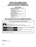
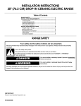
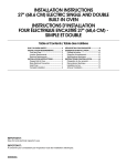
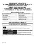
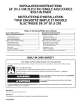
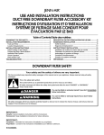
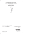
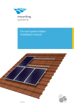
INSTALLATION INSTRUCTIONS
24" (61.0 CM) ELECTRIC SINGLE AND DOUBLE
BUILT-IN OVEN
Table of Contents
BUILT-IN OVEN SAFETY............................................................... 1
INSTALLATION REQUIREMENTS................................................ 2
Tools and Parts............................................................................ 2
Location Requirements ............................................................... 2
Electrical Requirements............................................................... 3
INSTALLATION INSTRUCTIONS.................................................. 4
Prepare Built-In Oven .................................................................. 4
Oven Door.................................................................................... 4
Make Electrical Connection......................................................... 5
Install Oven .................................................................................. 7
Complete Installation................................................................... 8
BUILT-IN OVEN SAFETY
Your safety and the safety of others are very important.
We have provided many important safety messages in this manual and on your appliance. Always read and obey all safety
messages.
This is the safety alert symbol.
This symbol alerts you to potential hazards that can kill or hurt you and others.
All safety messages will follow the safety alert symbol and either the word “DANGER” or “WARNING.”
These words mean:
DANGER
WARNING
You can be killed or seriously injured if you don't immediately
follow instructions.
You can be killed or seriously injured if you don't follow
instructions.
All safety messages will tell you what the potential hazard is, tell you how to reduce the chance of injury, and tell you what can
happen if the instructions are not followed.
IMPORTANT:
Save for local electrical inspector's use.
W10203506A
INSTALLATION REQUIREMENTS
Tools and Parts
Product Dimensions - Single Oven
Gather the required tools and parts before starting installation.
Read and follow the instructions provided with any tools listed
here.
A
Tools needed
■
Phillips screwdriver
■
Measuring tape
■
Hand or electric drill (for wall cabinet installations)
■
1" (25 mm) drill bit (for wall cabinet installations)
■
Level
B
E
Parts needed
■
UL listed or CSA approved conduit connector
■
UL listed wire connectors
Parts supplied
■
0.188 x 2.1" screws - single oven (4), double oven (6)
Check local codes. Check existing electrical supply. See
“Electrical Requirements.”
It is recommended that all electrical connections be made by a
licensed, qualified electrical installer.
D
C
A. 22¹⁄₄" (56.5 cm) max. recessed width
B. 29⁵⁄₈" (75.3 cm) max. overall height
C. 23⁷⁄₈" (60.6 cm) overall width
D. 22⁵⁄₈" (57.5 cm) max. recessed depth
E. 27⁷⁄₈" (70.8 cm) recessed height
Cabinet Dimensions - Single Oven
Location Requirements
IMPORTANT: Observe all governing codes and ordinances.
■ Cabinet opening dimensions that are shown must be used.
Given dimensions provide minimum clearance with oven.
■
A
Recessed installation area must provide complete enclosure
around the recessed portion of the oven.
■
Grounded electrical supply is required. See “Electrical
Requirements” section.
■
Electrical supply junction box should be located in the upper
right corner, 4" (10.2 cm) below the upper cut out surface of
the cabinet.
■
Single Oven Installed in Cabinet
Oven support surface must be solid, level and flush with
bottom of cabinet cutout. Floor must be able to support a
single oven weight of 154 lbs (70 kg) or a double oven weight
of 287 lbs (130 kg).
B
F
D
E
C
A. 24" (61 cm) min. cabinet width
B. 1¹⁄₂" (3.8 cm) top of cutout to bottom of upper cabinet
door
C. 33¹⁄₄" (84.5 cm) min. bottom of cutout to floor
D. 22³⁄₈" (56.8 cm) cutout width
E. 1¹⁄₂" (3.8 cm) min. bottom of cutout to top of cabinet door
F. 28¹¹⁄₁₆" (72.9 cm) cutout height
2
Product Dimensions - Double Oven
Cabinet Side View - Double or Single Oven
A
A
B
B
E
D
C
E
A. 24"(61 cm) min. cutout depth
B. 22⁵⁄₈" (57.5 cm) recessed oven depth
C. Oven front
D. Recessed oven
E. Cabinet
C
D
Electrical Requirements
A. 22¹⁄₄" (56.5 cm) max. recessed width
B. 46⁵⁄₁₆" (117.6 cm) max. overall height
C. 23⁷⁄₈" (60.6 cm) overall width
D. 22⁵⁄₈" (57.5 cm) max. recessed depth
E. 44⁵⁄₈" (113.4 cm) recessed height
Cabinet Dimensions - Double Oven
Double Oven Installed in Cabinet
A
B
F
If codes permit and a separate ground wire is used, it is
recommended that a qualified electrical installer determine that
the ground path and the wire gauge are in accordance with local
codes.
Check with a qualified electrical installer if you are not sure the
oven is properly grounded.
This oven must be connected to a grounded metal, permanent
wiring system.
Be sure that the electrical connection and wire size are adequate
and in conformance with the National Electrical Code, ANSI/
NFPA 70-latest edition or CSA Standards C22.1-94, Canadian
Electrical Code, Part 1 and C22.2 No. O-M91-latest edition, and
all local codes and ordinances.
A copy of the above code standards can be obtained from:
National Fire Protection Association
One Batterymarch Park
Quincy, MA 02269
CSA International
8501 East Pleasant Valley Road
Cleveland, OH 44131-5575
D
Electrical Connection
E
C
A. 24" (61 cm) min. cabinet width
B. 1¹⁄₂" (3.8 cm) top of cutout to bottom of upper
cabinet door
C. 17" (43.2 cm) min. bottom of cutout to floor
D. 22³⁄₈" (56.8 cm) cutout width
E. 1¹⁄₂" (3.8 cm) min. bottom of cutout to top of
cabinet door
F. 45³⁄₈" (115.3 cm) cutout height
To properly install your oven, you must determine the type of
electrical connection you will be using and follow the instructions
provided for it here.
■ Oven must be connected to the proper electrical voltage and
frequency as specified on the model/serial number rating
plate. The model/serial number rating plate is located at the
bottom right-hand oven surface. See the following illustration.
3
■
A circuit breaker (or time-delay fuse) is recommended.
■
Connect directly to the circuit breaker box (or fused
disconnect) through flexible, armored or nonmetallic
sheathed, copper cable (with grounding wire). See “Make
Electrical Connection” section.
■
Flexible conduit from the oven should be connected directly
to the junction box.
■
Do not cut the conduit. The length of conduit provided is for
serviceability of the oven.
■
A UL listed or CSA approved conduit connector must be
provided.
■
If the house has aluminum wiring follow the procedure below:
A
A
Single Oven
A. Model/serial number plate
Double Oven
A. Model/serial number plate
■
Double oven model rated from 6.5 kw to 8.6 kw at 208 V to
240 V requires a separate 40 amp circuit.
■
Single oven model rated at 4.4 kw to 5.8 kw at 208 V to 240 V
requires a separate 30 amp circuit.
1. Connect a section of solid copper wire to the ends of the
flexible conduit leads.
2. Connect the aluminum wiring to the added section of
copper wire using special connectors and/or tools
designed and UL listed for joining copper to aluminum.
Follow the electrical connector manufacturer's recommended
procedure. Aluminum/copper connection must conform with
local codes and industry accepted wiring practices.
INSTALLATION INSTRUCTIONS
Prepare Built-In Oven
1. Decide on the final location for the oven. Locate existing
wiring to avoid drilling into or severing wiring during
installation.
WARNING
Remove Oven Door.
IMPORTANT: Use both hands to remove oven doors.
1. Open door to the broil stop position (about 4 to 6 inches).
2. Grasp sides of the door at the middle. Slowly lift door straight
up.
Excessive Weight Hazard
Use two or more people to move and install oven.
Failure to do so can result in back or other injury.
2. To avoid floor damage, set the oven onto cardboard prior to
installation. Do not use handle or any portion of the front
frame or trim for lifting.
3. Remove the shipping materials and tape from the oven.
4. Remove the hardware package from inside the bag
containing literature.
5. Remove and set aside racks and other parts from inside the
oven.
6. Move oven and cardboard close to the oven’s final location.
4
3. While lifting the door up, very slightly open the door by pulling
it forward. Check that the latches swing down into the
notches on the hinge arms.
Make Electrical Connection
For Double Ovens
For Single Ovens
WARNING
WARNING
Electrical Shock Hazard
Electrical Shock Hazard
Disconnect power before servicing.
Disconnect power before servicing.
Use 8 gauge solid copper wire.
Use 12 gauge solid copper wire.
Electrically ground oven.
Electrically ground oven.
Failure to follow these instructions can result in death,
fire, or electrical shock.
Failure to follow these instructions can result in death,
fire, or electrical shock.
Make Electrical Connection
This oven is manufactured with a neutral (white) power supply
wire and a cabinet-connected green (or bare) ground wire twisted
together.
1. Disconnect power.
2. Feed the flexible conduit from the oven through the opening
in the cabinet.
3. Remove junction box cover, if it is present.
4. Install a UL listed or CSA approved conduit connector to the
junction box.
Electrical Connection Options Chart
If your home has:
Go to section:
4-wire
4-wire Cable from Home
Power Supply
½"
(1.3 cm)
3-wire
3-wire Cable from Home
Power Supply
A
A. UL listed or CSA approved conduit connector
½"
(1.3 cm)
5. Route the flexible conduit from the oven to the junction box
through a UL listed or CSA approved conduit connector.
6. Tighten screws on conduit connector.
7. See “Electrical Connection Options Chart” to complete
installation for your type of electrical connection.
5
4-Wire Cable from Home Power Supply
3-Wire Cable from Home Power Supply - U.S. Only
IMPORTANT: Use the 4-wire cable from home power supply in
the U.S. where local codes do not allow grounding through
neutral, New Branch circuit installations (1996 NEC), mobile
homes and recreational vehicles, new construction and in
Canada.
A
B
IMPORTANT: Use the 3-wire cable from home power supply
where local codes permit a 3-wire connection.
A
B
C
E
F
G
G
H
D
E
C
H
D
I
A. Cable from home power supply
B. Black wires
C. Red wires
D. 4-wire flexible conduit from
oven
E. Junction box
F. White wires
G. UL listed wire connectors
H. Green (or bare) ground wires
I. UL listed or CSA approved
conduit connector
1. Connect the 2 black wires (B) together using a UL listed wire
connector.
2. Connect the 2 red wires (C) together using a UL listed wire
connector.
3. Untwist white wire from green (or bare) ground wire coming
from the oven.
4. Connect the 2 white wires (F) together using a UL listed wire
connector.
5. Connect the green (or bare) ground wire (H) from the oven
cable to the green (or bare) ground wire (in the junction box)
using a UL listed wire connector.
6. Install junction box cover.
6
F
A. Cable from home power supply
B. Junction box
C. Black wires
D. White wires
E. Green (or bare) ground wire
(from oven)
I
F. 4-wire flexible conduit from
oven
G. Red wires
H. UL listed wire connectors
I. UL listed or CSA approved
conduit connector
1. Connect the 2 black wires (C) together using a UL listed wire
connector.
2. Connect the 2 white wires (D) and the green (or bare) ground
wire (of the oven cable) using a UL listed wire connector.
3. Connect the 2 red wires (G) together using a UL listed wire
connector.
4. Install junction box cover.
Install Oven
WARNING
Excessive Weight Hazard
Use two or more people to move and install oven.
3. Securely fasten oven to cabinet using the 0.188 x 2.1" screws
(4 for single oven, 6 for double oven) provided. Insert the
screws through holes in decorative trim. To avoid cabinet
damage, use the 0.140" diameter (number 28) drill bit to predrill the pilot holes before driving screws. Do not overtighten
screws.
Failure to do so can result in back or other injury.
1. Using 2 or more people, lift oven partially into cabinet cutout.
Use the oven opening as an area to grip.
NOTE: Push against seal area of oven front frame when
pushing oven into cabinet. Do not push against outside
edges.
A
B
A. Decorative trim
B. Insert screw.
2. Push oven completely into cabinet and center oven into
cabinet cutout.
4. Replace oven racks.
5. Grasp sides of the door and align slots in door with the hinge
arms.
6. Slightly pull the door open as you slide the door down onto
the hinge arms. The sliding action of the door will disengage
the latches on the hinge arms.
7. Gently push the door downward until the door rests evenly on
the hinges.
8. Close door.
9. Repeat for lower oven door.
10. Reconnect power.
11. Display panel will light briefly, and “PF” should appear in the
display.
12. If display panel does not light, please reference the
“Assistance or Service” section of the Use and Care Guide or
contact the dealer from whom you purchased your oven.
7
Complete Installation
1. Check that all parts are now installed. If there is an extra part,
go back through the steps to see which step was skipped.
2. Check that you have all of your tools.
3. Dispose of/recycle all packaging materials.
4. For oven use and cleaning, read the Use and Care Guide.
Check Operation of Oven(s)
1. Turn power on. The time should flash in the display.
2. Check that the oven door(s) is closed
3. Turn on the oven(s) Broil function. See the User Instructions
for more information.
If oven(s) does not operate, check the following:
■
■
Electrical supply is connected.
■
See “Troubleshooting” section in the Use and Care Guide.
4. When oven has been on for 5 minutes, feel for heat.
If you do not feel heat or if an “F” followed by a number
appears in the display, turn off the oven and contact a
qualified technician.
5. Press CANCEL.
If you need Assistance or Service:
Please reference the “Assistance or Service” section of the Use
and Care Guide or contact the dealer from whom you purchased
your built-in oven.
Household fuse is intact and tight; or circuit breaker has
not tripped.
W10203506A
© 2008
All rights reserved.
®Registered Trademark/ ™ Trademark of Maytag Corporation or its related companies.
7/08
Printed in U.S.A.