1
M3046A M2, M3 and M4 Monitors
M3000A Measurement Server &
M3015A & M3016A Measurement
Server Extensions
Service Guide
M3046-9060C
Printed in Germany. June 2000
Third Edition
Notice
This document contains proprietary information which is protected by copyright. All Rights
Reserved. Reproduction, adaptation, or translation without prior written permission is
prohibited, except as allowed under the copyright laws.
Agilent Technologies Deutschland GmbH
Herrenberger Strasse 130
71034 Böblingen, Germany
Publication number
M3046-9060C
Printed in Germany
:DUUDQW\
The information contained in this document is subject to change without notice.
Agilent Technologies makes no warranty of any kind with regard to this material, including,
but not limited to, the implied warranties or merchantability and fitness for a particular
purpose.
Agilent Technologies shall not be liable for errors contained herein or for incidental or
consequential damages in connection with the furnishing, performance, or use of this
material.
Copyright © Agilent Technologies, 1997, 1999, 2000
ii
Printing History
New editions of this document will incorporate all material updated since the previous
edition. Update packages may be issued between editions and contain replacement and
additional pages to be merged by a revision date at the bottom of the page. Note that pages
which are rearranged due to changes on a previous page are not considered revised.
The documentation printing date and part number indicate its current edition. The printing
date changes when a new edition is printed. (Minor corrections and updates which are
incorporated at reprint do not cause the date to change.) The document part number changes
when extensive technical changes are incorporated.
First Edition...............................................July 1997
Second Edition.........................................February 1999
Third Edition............................................June 2000
iii
Introduction
The M3000A Multi-Measurement Server, the M301A and M3016A Measurement Server
Extensions and the M3046A Compact Portable Patient Monitor form a flexible, portable,
battery or line powered patient monitor.
The M3000A Multi-Measurement Server acquires the physiological signals ECG, respiration,
invasive and non-invasive blood pressure, oxygen saturation of the blood, and temperature.
These signals are converted into digital data, and processed before being communicated to
the Monitor.
The M301A/M3016A Measurement Server Extensions acquire the physiological signals
invasive blood pressure, CO2 respiratory gas measurement, and temperature. These signals
are converted into digital data, and processed before being communicated to the Monitor.
The M3046A Compact Portable Patient Monitor receives the processed data from the
Measurement Server, and, if present, the Measurement Server Extension, examines it for
alarm conditions and displays it. The Monitor also provides operating controls for the user,
and interfaces to other devices.
The M3080A #C32 12V adapter allows use of a vehicle power supply for the instrument and
the M3080A #C30 battery charger allows the recharging of batteries for the instrument.
iv
Responsibility of the Manufacturer
Agilent Technologies only considers itself responsible for any effects on safety, reliability
and performance of the equipment if:
• assembly operations, extensions, re-adjustments, modifications or repairs are carried out by
persons authorized by Agilent, and
• the electrical installation of the relevant room complies with national standards, and
• the instrument is used in accordance with the instructions for use.
To ensure safety, use only those Agilent parts and accessories specified for use with the
Monitor. If non-Agilent parts are used, Agilent Technologies is not liable for any damage
that these parts may cause to the equipment.
v
In this Book
This Service Guide contains technical details on the Monitor, Measurement Server and
Measurement Server Extensions.
The purpose of this book is to provide a technical foundation for the monitoring system in
order to support effective troubleshooting and repair. The book is not intended to be a
comprehensive, in-depth explanation of the product architecture or technical implementation.
Rather, it is developed to offer enough information on the functions and operations of the
monitoring systems so that engineers who repair them are better able to understand how they
work.
It covers the physiological measurements that the products are designed to provide, the
Measurement Server that acquires those measurements, and the monitoring system that
displays them.
:KR6KRXOG8VHWKLV%RRN
If you are a biomedical engineer or a technician responsible for troubleshooting, repairing,
and maintaining Agilent’s patient monitoring systems, this book is designed for you. If you
are new to Agilent’s product line or monitoring systems, you may find this book helpful as an
orientation to the equipment. If you have already worked on the systems and now want
further details on how they work, you are likely to find much of the information you need
here.
&RQYHQWLRQV8VHGLQWKLV%RRN
:$51,1*
&$87,21
vi
:DUQLQJVFRQWDLQLQIRUPDWLRQ\RXVKRXOGNQRZWRDYRLGLQMXULQJSDWLHQWVDQG
SHUVRQQHO
Cautions contain information you should know to avoid damaging your equipment.
Notice . . . . . . . . . . . . . . . . . . . . . . . . . . . . . . . . . . . . . . . . . . . . . . . . . . . ii
Warranty . . . . . . . . . . . . . . . . . . . . . . . . . . . . . . . . . . . . . . . . . . . . . ii
Printing History . . . . . . . . . . . . . . . . . . . . . . . . . . . . . . . . . . . . . . . . . . . iii
Introduction . . . . . . . . . . . . . . . . . . . . . . . . . . . . . . . . . . . . . . . . . . . . . . iv
Responsibility of the Manufacturer . . . . . . . . . . . . . . . . . . . . . . . . . . . . v
In this Book . . . . . . . . . . . . . . . . . . . . . . . . . . . . . . . . . . . . . . . . . . . . . . vi
Who Should Use this Book . . . . . . . . . . . . . . . . . . . . . . . . . . . . . . . vi
Conventions Used in this Book . . . . . . . . . . . . . . . . . . . . . . . . . . . . vi
Objectives. . . . . . . . . . . . . . . . . . . . . . . . . . . . . . . . . . . . . . . . . . . . . . . . 1-1
Concepts. . . . . . . . . . . . . . . . . . . . . . . . . . . . . . . . . . . . . . . . . . . . . . . . . 1-1
Introducing the Instrument Components . . . . . . . . . . . . . . . . . . . . . . . . 1-2
Instrument Components . . . . . . . . . . . . . . . . . . . . . . . . . . . . . . . . . . . . . 1-3
A Quick Description of the Monitor . . . . . . . . . . . . . . . . . . . . . . . . . . . 1-4
Front Panel Keys . . . . . . . . . . . . . . . . . . . . . . . . . . . . . . . . . . . . . . . 1-4
Front of Monitor . . . . . . . . . . . . . . . . . . . . . . . . . . . . . . . . . . . . . . . 1-4
Back of Monitor. . . . . . . . . . . . . . . . . . . . . . . . . . . . . . . . . . . . . . . . 1-5
A Quick Description of the Measurement Server . . . . . . . . . . . . . . . . . 1-6
Overview of the M3000A Measurement Server . . . . . . . . . . . . . . . 1-6
M3000A Measurement Connectors . . . . . . . . . . . . . . . . . . . . . . . . 1-6
Measurement Connectors for the M3000A #D06 Measurement Server 1-6
A Quick Description of the Measurement Server Extension . . . . . . . . . 1-7
Overview of the Measurement Server Extensions M3015A & M3016A 1-7
Measurement Connectors for the M3015A Measurement Server
Extension . . . . . . . . . . . . . . . . . . . . . . . . . . . . . . . . . . . . . . . . . . 1-7
Measurement Connectors for the M3016AMeasurement Server
Extension . . . . . . . . . . . . . . . . . . . . . . . . . . . . . . . . . . . . . . . . . . 1-7
A Quick Description of the Main Screen. . . . . . . . . . . . . . . . . . . . . . . . 1-8
Theories of Operation and Functional Descriptions . . . . . . . . . . . . . . . 1-9
Section 1 - Monitor Description. . . . . . . . . . . . . . . . . . . . . . . . . . . . . . . 1-10
Monitor Theory of Operation. . . . . . . . . . . . . . . . . . . . . . . . . . . . . . . . . 1-11
Display and User Interface Software Module . . . . . . . . . . . . . . . . . 1-12
Alarm Manager Software Module . . . . . . . . . . . . . . . . . . . . . . . . . 1-12
Admit / Discharge / Transfer (ADT) Software Module . . . . . . . . . 1-12
Trend Software Module . . . . . . . . . . . . . . . . . . . . . . . . . . . . . . . . . 1-12
Events Software Module . . . . . . . . . . . . . . . . . . . . . . . . . . . . . . . . . 1-12
Printer Manager . . . . . . . . . . . . . . . . . . . . . . . . . . . . . . . . . . . . . . . . 1-13
IrDA Manager . . . . . . . . . . . . . . . . . . . . . . . . . . . . . . . . . . . . . . . . . 1-13
Communication Software Module . . . . . . . . . . . . . . . . . . . . . . . . . 1-13
Support Services . . . . . . . . . . . . . . . . . . . . . . . . . . . . . . . . . . . . . . . 1-14
Functional Description of the Monitor Hardware . . . . . . . . . . . . . . . . . 1-15
Display Video Controller . . . . . . . . . . . . . . . . . . . . . . . . . . . . . . . . 1-16
Human Interface Controller . . . . . . . . . . . . . . . . . . . . . . . . . . . . . . 1-17
Visual Indicators . . . . . . . . . . . . . . . . . . . . . . . . . . . . . . . . . . . . .1-17
i
Alarm Relay . . . . . . . . . . . . . . . . . . . . . . . . . . . . . . . . . . . . . . . . 1-17
Battery Controller . . . . . . . . . . . . . . . . . . . . . . . . . . . . . . . . . . . . . . .1-17
ECG Out/Marker In Controller . . . . . . . . . . . . . . . . . . . . . . . . . . . . .1-17
Infrared (IrDA) Interface . . . . . . . . . . . . . . . . . . . . . . . . . . . . . . . . .1-18
Wireless LAN Interface . . . . . . . . . . . . . . . . . . . . . . . . . . . . . . . . . .1-18
Section 2 - Measurement Server Description and Features. . . . . . . . . . .1-19
M3000A Measurement Server Standard Package . . . . . . . . . . . . . .1-19
M3000A Measurement Server Noninvasive Measurements
Package . . . . . . . . . . . . . . . . . . . . . . . . . . . . . . . . . . . . . . . . . . . .1-19
Features . . . . . . . . . . . . . . . . . . . . . . . . . . . . . . . . . . . . . . . . . . . . . . .1-19
Data Management . . . . . . . . . . . . . . . . . . . . . . . . . . . . . . . . . . . . 1-19
Settings Transfer . . . . . . . . . . . . . . . . . . . . . . . . . . . . . . . . . . . . . 1-19
Alarms Reset . . . . . . . . . . . . . . . . . . . . . . . . . . . . . . . . . . . . . . . . 1-20
Server-to-Monitor Link Bar . . . . . . . . . . . . . . . . . . . . . . . . . . . . 1-20
Measurement Server Theory of Operation . . . . . . . . . . . . . . . . . . . . . . .1-21
Functional Description of the Measurement Server Hardware . . . . . . .1-22
Electrocardiogram/Respiration (ECG/Resp) Measurement . . . . . . . . . .1-23
Description . . . . . . . . . . . . . . . . . . . . . . . . . . . . . . . . . . . . . . . . . . . .1-23
Measurements . . . . . . . . . . . . . . . . . . . . . . . . . . . . . . . . . . . . . . . . . .1-23
ECG/Resp Features . . . . . . . . . . . . . . . . . . . . . . . . . . . . . . . . . . . . . .1-23
ECG Modes . . . . . . . . . . . . . . . . . . . . . . . . . . . . . . . . . . . . . . . . 1-23
Resp Modes . . . . . . . . . . . . . . . . . . . . . . . . . . . . . . . . . . . . . . . . 1-23
Safety . . . . . . . . . . . . . . . . . . . . . . . . . . . . . . . . . . . . . . . . . . . . . 1-24
Block Diagram of the ECG/Resp . . . . . . . . . . . . . . . . . . . . . . . . . .1-24
Theory of Operation . . . . . . . . . . . . . . . . . . . . . . . . . . . . . . . . . . . . .1-24
Transducer . . . . . . . . . . . . . . . . . . . . . . . . . . . . . . . . . . . . . . . . . 1-24
Input Protection Network . . . . . . . . . . . . . . . . . . . . . . . . . . . . . . 1-24
ECG ASIC . . . . . . . . . . . . . . . . . . . . . . . . . . . . . . . . . . . . . . . . . 1-24
Excitation Current Source . . . . . . . . . . . . . . . . . . . . . . . . . . . . . . 1-25
Bridge & Amplifier . . . . . . . . . . . . . . . . . . . . . . . . . . . . . . . . . . . 1-25
The Central Processing Unit (CPU) . . . . . . . . . . . . . . . . . . . . . . 1-25
Non-invasive Blood Pressure (NBP) Measurement . . . . . . . . . . . . . . . .1-26
Description . . . . . . . . . . . . . . . . . . . . . . . . . . . . . . . . . . . . . . . . . . . .1-26
Measurements . . . . . . . . . . . . . . . . . . . . . . . . . . . . . . . . . . . . . . . . . .1-26
NBP Features . . . . . . . . . . . . . . . . . . . . . . . . . . . . . . . . . . . . . . . . . .1-26
NBP Modes . . . . . . . . . . . . . . . . . . . . . . . . . . . . . . . . . . . . . . . . . 1-27
Safety . . . . . . . . . . . . . . . . . . . . . . . . . . . . . . . . . . . . . . . . . . . . . 1-27
Block Diagram for NBP . . . . . . . . . . . . . . . . . . . . . . . . . . . . . . . . .1-28
Components . . . . . . . . . . . . . . . . . . . . . . . . . . . . . . . . . . . . . . . . . . .1-29
Theory of Operation . . . . . . . . . . . . . . . . . . . . . . . . . . . . . . . . . . . . .1-29
Arterial Oxygen Saturation and Pleth (SpO2/PLETH) Measurement . . .1-30
Description . . . . . . . . . . . . . . . . . . . . . . . . . . . . . . . . . . . . . . . . . . . .1-30
Measurements . . . . . . . . . . . . . . . . . . . . . . . . . . . . . . . . . . . . . . . . . .1-30
ii
SpO2/PLETH Features . . . . . . . . . . . . . . . . . . . . . . . . . . . . . . . . . 1-30
Safety . . . . . . . . . . . . . . . . . . . . . . . . . . . . . . . . . . . . . . . . . . . . .1-30
PLETH Wave . . . . . . . . . . . . . . . . . . . . . . . . . . . . . . . . . . . . . . .1-30
Block Diagram of the SpO2/PLETH Circuit . . . . . . . . . . . . . . . . . 1-31
Theory of Operation . . . . . . . . . . . . . . . . . . . . . . . . . . . . . . . . . . . . 1-31
LED Current Source . . . . . . . . . . . . . . . . . . . . . . . . . . . . . . . . . .1-31
Photo Amplifier . . . . . . . . . . . . . . . . . . . . . . . . . . . . . . . . . . . . . .1-31
Variable Gain . . . . . . . . . . . . . . . . . . . . . . . . . . . . . . . . . . . . . . .1-32
Analog to Digital Converter (ADC) . . . . . . . . . . . . . . . . . . . . . .1-32
Digital Signal Processor (DSP) . . . . . . . . . . . . . . . . . . . . . . . . . .1-32
Self-Test Signal Generator . . . . . . . . . . . . . . . . . . . . . . . . . . . . .1-32
RCode Measurement Circuit . . . . . . . . . . . . . . . . . . . . . . . . . . . .1-32
CPU, ROM/RAM and ASIC . . . . . . . . . . . . . . . . . . . . . . . . . . . .1-32
SpO2 Algorithm . . . . . . . . . . . . . . . . . . . . . . . . . . . . . . . . . . . . . . .1-32
Temperature and Invasive Blood Pressure (Temp/Press) measurement 1-34
Description . . . . . . . . . . . . . . . . . . . . . . . . . . . . . . . . . . . . . . . . . . . 1-34
Measurements . . . . . . . . . . . . . . . . . . . . . . . . . . . . . . . . . . . . . . . . . 1-34
Temp/Press Features . . . . . . . . . . . . . . . . . . . . . . . . . . . . . . . . . . . . 1-34
Press Wave . . . . . . . . . . . . . . . . . . . . . . . . . . . . . . . . . . . . . . . . .1-34
Temp Mode . . . . . . . . . . . . . . . . . . . . . . . . . . . . . . . . . . . . . . . . .1-34
Safety . . . . . . . . . . . . . . . . . . . . . . . . . . . . . . . . . . . . . . . . . . . . .1-35
Block Diagram . . . . . . . . . . . . . . . . . . . . . . . . . . . . . . . . . . . . . . . . 1-35
Theory of Operation . . . . . . . . . . . . . . . . . . . . . . . . . . . . . . . . . . . . 1-35
Excitation Voltage . . . . . . . . . . . . . . . . . . . . . . . . . . . . . . . . . . . .1-35
Input Protection Network . . . . . . . . . . . . . . . . . . . . . . . . . . . . . .1-35
Transducer Detection . . . . . . . . . . . . . . . . . . . . . . . . . . . . . . . . .1-35
Current Source . . . . . . . . . . . . . . . . . . . . . . . . . . . . . . . . . . . . . .1-36
Resistor Array . . . . . . . . . . . . . . . . . . . . . . . . . . . . . . . . . . . . . . .1-36
Analog to Digital Converter (ADC) . . . . . . . . . . . . . . . . . . . . . .1-36
The Central Processing Unit . . . . . . . . . . . . . . . . . . . . . . . . . . . .1-36
Temperature and Invasive Pressure Software . . . . . . . . . . . . . . . . . 1-36
Block Diagram of the Temp/Press Software . . . . . . . . . . . . . . . . . . 1-37
System CPU Communication . . . . . . . . . . . . . . . . . . . . . . . . . . .1-37
ADC Controller and Data Acquisition . . . . . . . . . . . . . . . . . . . .1-37
Wave Processing and Filtering . . . . . . . . . . . . . . . . . . . . . . . . . .1-37
Pressure & Temperature Mode Detector . . . . . . . . . . . . . . . . . .1-38
Block diagram of the Temperature Software Module . . . . . . . .1-38
Signal Acquisition . . . . . . . . . . . . . . . . . . . . . . . . . . . . . . . . . . . .1-38
Average Calculation . . . . . . . . . . . . . . . . . . . . . . . . . . . . . . . . . .1-38
Temperature Alarming . . . . . . . . . . . . . . . . . . . . . . . . . . . . . . . .1-38
Temperature User Controls . . . . . . . . . . . . . . . . . . . . . . . . . . . . .1-38
Section 3 - Measurement Server Extensions Description and Features. 1-39
M3015A Measurement Server Extension . . . . . . . . . . . . . . . . . .1-39
iii
M3016A Measurement Server Extension . . . . . . . . . . . . . . . . . . 1-39
Features . . . . . . . . . . . . . . . . . . . . . . . . . . . . . . . . . . . . . . . . . . . . . . .1-39
Data Management . . . . . . . . . . . . . . . . . . . . . . . . . . . . . . . . . . . . 1-39
Settings Transfer . . . . . . . . . . . . . . . . . . . . . . . . . . . . . . . . . . . . . 1-39
Alarms Reset . . . . . . . . . . . . . . . . . . . . . . . . . . . . . . . . . . . . . . . . 1-40
Server-to-Monitor Link Bar . . . . . . . . . . . . . . . . . . . . . . . . . . . . 1-40
M3015A Measurement Server Extension Theory of Operation . . . . . . .1-41
Functional Description of the M3015A Measurement Server Extension Hardware1-41
Hardware Block Diagram . . . . . . . . . . . . . . . . . . . . . . . . . . . . . . . . .1-42
Main Functional Areas . . . . . . . . . . . . . . . . . . . . . . . . . . . . . . . . 1-42
Sidestream CO2 Measurement. . . . . . . . . . . . . . . . . . . . . . . . . . . . . . . . .1-43
Description . . . . . . . . . . . . . . . . . . . . . . . . . . . . . . . . . . . . . . . . . . . .1-43
Measurements . . . . . . . . . . . . . . . . . . . . . . . . . . . . . . . . . . . . . . . . . .1-43
Sidestream CO2 Features . . . . . . . . . . . . . . . . . . . . . . . . . . . . . . . . .1-44
Sidestream CO2 Wave . . . . . . . . . . . . . . . . . . . . . . . . . . . . . . . . 1-44
Measurement Mode . . . . . . . . . . . . . . . . . . . . . . . . . . . . . . . . . . 1-44
Block Diagram of the Sidestream CO2 measurement . . . . . . . . . . .1-46
Theory of Operation for M3015A sidestream CO2 . . . . . . . . . . . . . . . . 1-46
Flow System . . . . . . . . . . . . . . . . . . . . . . . . . . . . . . . . . . . . . . . . 1-46
Temperature Sensor . . . . . . . . . . . . . . . . . . . . . . . . . . . . . . . . . . 1-46
Exciter and Infrared Source . . . . . . . . . . . . . . . . . . . . . . . . . . . . 1-46
Detectors . . . . . . . . . . . . . . . . . . . . . . . . . . . . . . . . . . . . . . . . . . . 1-46
Pressure Sensor . . . . . . . . . . . . . . . . . . . . . . . . . . . . . . . . . . . . . . 1-47
Analog Section . . . . . . . . . . . . . . . . . . . . . . . . . . . . . . . . . . . . . . 1-47
Controller and Peripherals . . . . . . . . . . . . . . . . . . . . . . . . . . . . . 1-47
Gas Inlet with Optical Code Recognition . . . . . . . . . . . . . . . . . . 1-47
Serial Interface with FELP . . . . . . . . . . . . . . . . . . . . . . . . . . . . . 1-47
M3016A Measurement Server Extension Theory of Operation . . . . . . .1-48
Functional Description of the M3016A Measurement Server Extension Hardware1-49
Hardware Block Diagram . . . . . . . . . . . . . . . . . . . . . . . . . . . . . . . . .1-50
Main Functional Areas . . . . . . . . . . . . . . . . . . . . . . . . . . . . . . . . 1-50
Mainstream CO2 Measurement . . . . . . . . . . . . . . . . . . . . . . . . . . . . . . . .1-51
Description . . . . . . . . . . . . . . . . . . . . . . . . . . . . . . . . . . . . . . . . . . . .1-51
Measurements . . . . . . . . . . . . . . . . . . . . . . . . . . . . . . . . . . . . . . . . . .1-51
Mainstream CO2 Features . . . . . . . . . . . . . . . . . . . . . . . . . . . . . . . .1-52
Mainstream CO2 Wave . . . . . . . . . . . . . . . . . . . . . . . . . . . . . . . 1-53
Measurement Mode . . . . . . . . . . . . . . . . . . . . . . . . . . . . . . . . . . 1-53
Safety . . . . . . . . . . . . . . . . . . . . . . . . . . . . . . . . . . . . . . . . . . . . . 1-53
Block Diagram of the Mainstream CO2 measurement . . . . . . . . . . .1-54
Theory of Operation for the M3016A Mainstream CO2 . . . . . . . . . . . 1-55
Microprocessor . . . . . . . . . . . . . . . . . . . . . . . . . . . . . . . . . . . . . . 1-55
Temperature Sensor, Amplifier, AIO, Heater Control and Heater 1-55
Sense Coil, Motor Phase Comparator, Counters, Motor Drive, Drive Coil 1-55
iv
Infrared Detector, CO2 Input Amplifier, Dual Slope A/D, AZ Pulse Monoflop and Bias
Regulation . . . . . . . . . . . . . . . . . . . . . . . . . . . . . . . . . . . . . . .1-55
Answers to the Tutorial for the Introduction to the Instrument . . . . . . . 1-58
Objectives. . . . . . . . . . . . . . . . . . . . . . . . . . . . . . . . . . . . . . . . . . . . . . . . 2-1
Concepts. . . . . . . . . . . . . . . . . . . . . . . . . . . . . . . . . . . . . . . . . . . . . . . . . 2-1
Warnings, Cautions, and Safety Precautions . . . . . . . . . . . . . . . . . . . . . 2-2
Patient Safety . . . . . . . . . . . . . . . . . . . . . . . . . . . . . . . . . . . . . . . . . 2-2
Patient Leakage Current . . . . . . . . . . . . . . . . . . . . . . . . . . . . . . . . . 2-2
Preparing to Install the Monitor . . . . . . . . . . . . . . . . . . . . . . . . . . . . . . . 2-2
Power Source Requirements . . . . . . . . . . . . . . . . . . . . . . . . . . . . . . 2-2
Protecting against Electric Shock . . . . . . . . . . . . . . . . . . . . . . . . . . 2-2
Equipotential Grounding . . . . . . . . . . . . . . . . . . . . . . . . . . . . . . . . . 2-3
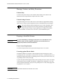
Combining Equipment . . . . . . . . . . . . . . . . . . . . . . . . . . . . . . . . . . 2-3
Environment . . . . . . . . . . . . . . . . . . . . . . . . . . . . . . . . . . . . . . . . . . 2-4
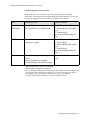
Explanation of symbols used: . . . . . . . . . . . . . . . . . . . . . . . . . . . . . 2-5
Unpacking the Monitor . . . . . . . . . . . . . . . . . . . . . . . . . . . . . . . . . . . . . 2-6
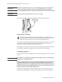
Installing the Monitor. . . . . . . . . . . . . . . . . . . . . . . . . . . . . . . . . . . . . . . 2-7
Making the Altitude Setting . . . . . . . . . . . . . . . . . . . . . . . . . . . .2-7
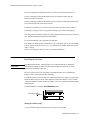
Connecting the M3000A Measurement Server.... . . . . . . . . . . . . . . . . . 2-9
...with the M3000A Measurement Server directly on the Monitor . 2-9
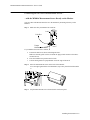
...with the M3000A Measurement Server Separate from the Monitor 2-10
...with the M3000A Measurement Server Attached to an M3015A/M3016A Measurement
Server Extension . . . . . . . . . . . . . . . . . . . . . . . . . . . . . . . . . . . . 2-11
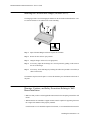
Attaching the Monitor to a Mount . . . . . . . . . . . . . . . . . . . . . . . . . . . . . 2-11
Detaching the Monitor from a Mount . . . . . . . . . . . . . . . . . . . . . . . . . . 2-11
Attaching the Measurement Server to a Mount . . . . . . . . . . . . . . . . . . . 2-12
Detaching the Measurement Server from a Mount . . . . . . . . . . . . . . . . 2-12
Positioning the Measurement Server on a Clamp Mount . . . . . . . . . . . 2-12
Connecting to the Nurse Call Relay. . . . . . . . . . . . . . . . . . . . . . . . . . . . 2-13
Installation of Wireless Infrastructure . . . . . . . . . . . . . . . . . . . . . . . . . . 2-13
Connecting to the ECG Output or Marker Input . . . . . . . . . . . . . . . . . . 2-14
Configuring the Monitor . . . . . . . . . . . . . . . . . . . . . . . . . . . . . . . . . . . . 2-14
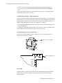
Installing an Additional Display . . . . . . . . . . . . . . . . . . . . . . . . . . . . . . 2-15
Installation . . . . . . . . . . . . . . . . . . . . . . . . . . . . . . . . . . . . . . . . . . . . 2-15
Installation Requirements According to IEC 601-1-1 . . . . . . . .2-16
Connecting the Display . . . . . . . . . . . . . . . . . . . . . . . . . . . . . . . . . . 2-16
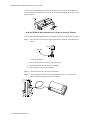
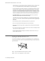
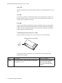
Installing the 12V Adapter . . . . . . . . . . . . . . . . . . . . . . . . . . . . . . . . . . . 2-17
Using the Battery Charger . . . . . . . . . . . . . . . . . . . . . . . . . . . . . . . . . . . 2-17
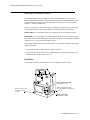
Connecting a Printer. . . . . . . . . . . . . . . . . . . . . . . . . . . . . . . . . . . . . . . . 2-18
Selecting a Printer . . . . . . . . . . . . . . . . . . . . . . . . . . . . . . . . . . . . . . 2-18
Installing the Wireless Infrared Printer Connector (M3080A #H02) . . 2-20
Connecting a Local Printer. . . . . . . . . . . . . . . . . . . . . . . . . . . . . . . . . . . 2-21
Connecting a Remote Printer . . . . . . . . . . . . . . . . . . . . . . . . . . . . . . . . . 2-21
v
Site Preparation Guidelines . . . . . . . . . . . . . . . . . . . . . . . . . . . . . . . . . . .2-22
Installing the Table Mount (M3080A #A10). . . . . . . . . . . . . . . . . . . . . .2-22
Installing the Universal Bed Hanger (M3080A #A11) . . . . . . . . . . . . . .2-23
Warnings, Cautions, and Safety Precautions Relating to Wall Mount Installation2-23
Installing the Wall Rail (M3080A #A13) . . . . . . . . . . . . . . . . . . . . . . . .2-24
Installing the Tilt/Swivel Mount (M3080A #A14) . . . . . . . . . . . . . . . . .2-26
Screwed Directly to a Wall . . . . . . . . . . . . . . . . . . . . . . . . . . . . . . . .2-26
Mounted to the GCX Wall Channel . . . . . . . . . . . . . . . . . . . . . . . . .2-27
Attached to a Universal Pole Clamp . . . . . . . . . . . . . . . . . . . . . . . . .2-28
Attached to the Monitor . . . . . . . . . . . . . . . . . . . . . . . . . . . . . . . . . .2-29
Installing the GCX Wall Channel (M3080A #A15) . . . . . . . . . . . . . . . .2-29
Installing the Universal Pole Clamp (M3080A #C05) . . . . . . . . . . . . . .2-30
Installing the Measurement Server Mounting Options . . . . . . . . . . . . . .2-31
Server Mounting Plate (M3080A #A01) . . . . . . . . . . . . . . . . . . . . .2-31
Server Mounting Plate (M3080A #A02) . . . . . . . . . . . . . . . . . . . . .2-32
Disposing of the Monitor, Measurement Server and Measurement Server Extensions2-33
Answers to the Tutorial for Installing the Instrument . . . . . . . . . . . . . . .2-36
Objectives . . . . . . . . . . . . . . . . . . . . . . . . . . . . . . . . . . . . . . . . . . . . . . . .3-1
Concepts . . . . . . . . . . . . . . . . . . . . . . . . . . . . . . . . . . . . . . . . . . . . . . . . .3-1
Recommendations for Maintenance Frequency . . . . . . . . . . . . . . . . . . .3-2
Maintenance Checklist. . . . . . . . . . . . . . . . . . . . . . . . . . . . . . . . . . . . . . .3-3
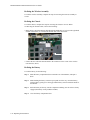
Inspecting the Instrument . . . . . . . . . . . . . . . . . . . . . . . . . . . . . . . . . . . .3-4
Inspect Cables and Cords . . . . . . . . . . . . . . . . . . . . . . . . . . . . . . . . .3-4
Preventive Maintenance Tasks . . . . . . . . . . . . . . . . . . . . . . . . . . . . . . . .3-5
M3046A . . . . . . . . . . . . . . . . . . . . . . . . . . . . . . . . . . . . . . . . . . . . . .3-5
Replacing the Backlight Tube Assembly . . . . . . . . . . . . . . . . . . 3-5
M3000A . . . . . . . . . . . . . . . . . . . . . . . . . . . . . . . . . . . . . . . . . . . . . .3-5
NBP Calibration and Performance tests . . . . . . . . . . . . . . . . . . . 3-5
M3015A . . . . . . . . . . . . . . . . . . . . . . . . . . . . . . . . . . . . . . . . . . . 3-5
Tools Required . . . . . . . . . . . . . . . . . . . . . . . . . . . . . . . . . . . . . . 3-6
Required Replacement Parts . . . . . . . . . . . . . . . . . . . . . . . . . . . . 3-6
Replacement of the Pump and CO2 Scrubber . . . . . . . . . . . . . . . . .3-7
Replacement of the Infrared Lamp . . . . . . . . . . . . . . . . . . . . . . . . . .3-7
General Cleaning of the Instrument. . . . . . . . . . . . . . . . . . . . . . . . . . . . .3-8
Cleaning Guidelines . . . . . . . . . . . . . . . . . . . . . . . . . . . . . . . . . . . . .3-8
Cleaning Agents . . . . . . . . . . . . . . . . . . . . . . . . . . . . . . . . . . . . . . . .3-9
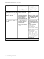
Battery Handling, Maintenance and Good Practices . . . . . . . . . . . . . . . .3-10
About the Battery . . . . . . . . . . . . . . . . . . . . . . . . . . . . . . . . . . . . . . .3-10
Checking the Battery Status . . . . . . . . . . . . . . . . . . . . . . . . . . . . . . .3-10
Charging the Battery . . . . . . . . . . . . . . . . . . . . . . . . . . . . . . . . . . . . .3-13
Conditioning a Battery . . . . . . . . . . . . . . . . . . . . . . . . . . . . . . . . . . .3-14
To condition the battery: . . . . . . . . . . . . . . . . . . . . . . . . . . . . . . . 3-14
Accessing the Battery Status Window . . . . . . . . . . . . . . . . . . . . . . .3-14
vi
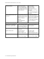
Battery INOP Messages . . . . . . . . . . . . . . . . . . . . . . . . . . . . . . . . . 3-15
Answers to the Tutorial for Maintaining the Instrument . . . . . . . . . . . . 3-18
Objectives. . . . . . . . . . . . . . . . . . . . . . . . . . . . . . . . . . . . . . . . . . . . . . . . 4-1
Concepts. . . . . . . . . . . . . . . . . . . . . . . . . . . . . . . . . . . . . . . . . . . . . . . . . 4-1
Test Reporting . . . . . . . . . . . . . . . . . . . . . . . . . . . . . . . . . . . . . . . . . . . . 4-2
Recommendations for Test Frequency. . . . . . . . . . . . . . . . . . . . . . . . . . 4-3
Test Map. . . . . . . . . . . . . . . . . . . . . . . . . . . . . . . . . . . . . . . . . . . . . . . . . 4-4
Testing Checklist . . . . . . . . . . . . . . . . . . . . . . . . . . . . . . . . . . . . . . . . . . 4-5
Serial Numbers. . . . . . . . . . . . . . . . . . . . . . . . . . . . . . . . . . . . . . . . . . . . 4-6
Passwords. . . . . . . . . . . . . . . . . . . . . . . . . . . . . . . . . . . . . . . . . . . . . . . . 4-6
Visual Test . . . . . . . . . . . . . . . . . . . . . . . . . . . . . . . . . . . . . . . . . . . . . . . 4-6
Power On Test . . . . . . . . . . . . . . . . . . . . . . . . . . . . . . . . . . . . . . . . . . . . 4-6
Functionality Assurance Tests . . . . . . . . . . . . . . . . . . . . . . . . . . . . . . . . 4-7
Performance Assurance Test . . . . . . . . . . . . . . . . . . . . . . . . . . . . . . 4-7
Quick System Check . . . . . . . . . . . . . . . . . . . . . . . . . . . . . . . . . . . . 4-7
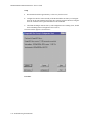
System Self-Test . . . . . . . . . . . . . . . . . . . . . . . . . . . . . . . . . . . . . . . 4-8
System Self-Test Values . . . . . . . . . . . . . . . . . . . . . . . . . . . . . . . . . 4-9
Preventive Maintenance Tests . . . . . . . . . . . . . . . . . . . . . . . . . . . . . . . . 4-10
NBP Accuracy, Leakage, Linearity and Valve Test . . . . . . . . . . . . 4-10
NBP Accuracy Test . . . . . . . . . . . . . . . . . . . . . . . . . . . . . . . . . . .4-10
NBP Leakage Test . . . . . . . . . . . . . . . . . . . . . . . . . . . . . . . . . . .4-11
NBP Linearity Test . . . . . . . . . . . . . . . . . . . . . . . . . . . . . . . . . . .4-11
Valve Test . . . . . . . . . . . . . . . . . . . . . . . . . . . . . . . . . . . . . . . . . .4-12
Sidestream CO2 Performance Test . . . . . . . . . . . . . . . . . . . . . . . . . 4-12
Tools Required . . . . . . . . . . . . . . . . . . . . . . . . . . . . . . . . . . . . . .4-13
Barometric Pressure Check and Calibration . . . . . . . . . . . . . . . .4-13
Leakage Check . . . . . . . . . . . . . . . . . . . . . . . . . . . . . . . . . . . . . .4-14
Pump Check . . . . . . . . . . . . . . . . . . . . . . . . . . . . . . . . . . . . . . . .4-15
Flow Rate Check and Calibration . . . . . . . . . . . . . . . . . . . . . . . .4-15
Noise Check . . . . . . . . . . . . . . . . . . . . . . . . . . . . . . . . . . . . . . . .4-16
CO2 Gas Measurement Calibration Check . . . . . . . . . . . . . . . . .4-16
Calibration Verification . . . . . . . . . . . . . . . . . . . . . . . . . . . . . . .4-17
Reset Time Counters . . . . . . . . . . . . . . . . . . . . . . . . . . . . . . . . . . . . 4-17
Accuracy and Performance Procedures . . . . . . . . . . . . . . . . . . . . . . . . . 4-19
Temperature Accuracy . . . . . . . . . . . . . . . . . . . . . . . . . . . . . . . . . . 4-19
ECG/Resp Performance . . . . . . . . . . . . . . . . . . . . . . . . . . . . . . . . . 4-19
ECG Performance . . . . . . . . . . . . . . . . . . . . . . . . . . . . . . . . . . . .4-19
Respiration Performance . . . . . . . . . . . . . . . . . . . . . . . . . . . . . . .4-19
Invasive Pressure Performance Test . . . . . . . . . . . . . . . . . . . . . . . . 4-20
SpO2 Performance Test . . . . . . . . . . . . . . . . . . . . . . . . . . . . . . . . . . 4-21
Mainstream CO2 Performance Test . . . . . . . . . . . . . . . . . . . . . . . . 4-21
Nurse Call Relay Performance Test . . . . . . . . . . . . . . . . . . . . . . . . 4-22
ECG Sync Performance Test . . . . . . . . . . . . . . . . . . . . . . . . . . . . . 4-22
vii
Patient Safety Checks . . . . . . . . . . . . . . . . . . . . . . . . . . . . . . . . . . . . . . .4-24
Warnings, Cautions, and Safety Precautions . . . . . . . . . . . . . . . . . .4-24
Safety Test Procedures . . . . . . . . . . . . . . . . . . . . . . . . . . . . . . . . . . .4-24
S(1) Part 1: System Enclosure Leakage Current - NC (normal condition) 4-25
S(1) Part 2: System Enclosure Leakage current - Single Fault (open earth) 4-26
Reporting safety test S(1) in the Service record . . . . . . . . . . . . . 4-26
S(2) Protective Earth Continuity . . . . . . . . . . . . . . . . . . . . . . . 4-27
Reporting safety test S(2) in the Service record . . . . . . . . . . . . . 4-27
S(3) Patient Leakage current - Single Fault Condition (S.F.C.) mains on applied part
4-28
Reporting safety test S(3) in the Service record . . . . . . . . . . . . . 4-28
Answers to the Tutorial for Testing the Instrument. . . . . . . . . . . . . . . . .4-30
Objectives . . . . . . . . . . . . . . . . . . . . . . . . . . . . . . . . . . . . . . . . . . . . . . . .5-1
Concepts . . . . . . . . . . . . . . . . . . . . . . . . . . . . . . . . . . . . . . . . . . . . . . . . .5-1
Part 1 Troubleshooting Checklists. . . . . . . . . . . . . . . . . . . . . . . . . . . . . .5-3
Checks for Obvious Problems . . . . . . . . . . . . . . . . . . . . . . . . . . . . .5-3
Checks Before Opening the Instrument . . . . . . . . . . . . . . . . . . . . . .5-3
Checks with the Instrument switched Off . . . . . . . . . . . . . . . . . 5-3
Checks with the Instrument Switched On, AC connected, without Battery 5-4
Checks with the Instrument Switched On, AC connected, with Battery 5-4
Checks with the Instrument Switched On, AC not Connected, with Battery 5-4
Troubleshooting the Front-Panel LEDs . . . . . . . . . . . . . . . . . . . 5-5
Troubleshooting the System Board LEDs . . . . . . . . . . . . . . . . . 5-6
Troubleshooting the Display Adapter Board LED . . . . . . . . . . . 5-7
Troubleshooting the Wireless Assembly LEDs . . . . . . . . . . . . . 5-7
Status LEDs . . . . . . . . . . . . . . . . . . . . . . . . . . . . . . . . . . . . . . . . 5-7
Radio LED . . . . . . . . . . . . . . . . . . . . . . . . . . . . . . . . . . . . . . . . . 5-8
Sync LED . . . . . . . . . . . . . . . . . . . . . . . . . . . . . . . . . . . . . . . . . . 5-8
Link LED . . . . . . . . . . . . . . . . . . . . . . . . . . . . . . . . . . . . . . . . . . 5-8
Troubleshooting the Measurement Server LEDs . . . . . . . . . . . . 5-8
First Steps . . . . . . . . . . . . . . . . . . . . . . . . . . . . . . . . . . . . . . . . . . . . .5-9
What To Do if the Monitor Cannot Be Switched On, AC powered 5-9
What To Do if the Monitor Cannot Be Switched On, Battery powered 5-9
Initial Instrument Boot Phase . . . . . . . . . . . . . . . . . . . . . . . . . . . . . .5-10
What Happens During a Regular Boot, AC powered, without Battery 5-10
What To do If the Display Remains Dark . . . . . . . . . . . . . . . . . 5-10
Isolating Problems to the Correct Subassembly . . . . . . . . . . . . . . . .5-11
Troubleshooting the ECG OUT . . . . . . . . . . . . . . . . . . . . . . . . . 5-11
Data Flow Marker In and ECG Wave . . . . . . . . . . . . . . . . . . . . 5-12
Part 2 Isolating and Solving Instrument Problems . . . . . . . . . . . . . . . . .5-13
INOP Messages . . . . . . . . . . . . . . . . . . . . . . . . . . . . . . . . . . . . . . . .5-13
Isolating the Defective Component . . . . . . . . . . . . . . . . . . . . . . . . .5-17
Part 3 Using Support Functions . . . . . . . . . . . . . . . . . . . . . . . . . . . . . . . .5-25
viii
The Status Log and Error Codes . . . . . . . . . . . . . . . . . . . . . . . . . . 5-25
List of Error Codes . . . . . . . . . . . . . . . . . . . . . . . . . . . . . . . . . . . . . 5-26
Testing Wireless Network Connectivity . . . . . . . . . . . . . . . . . . . . . . . . 5-31
Antenna Check . . . . . . . . . . . . . . . . . . . . . . . . . . . . . . . . . . . . . . . . 5-31
Setup . . . . . . . . . . . . . . . . . . . . . . . . . . . . . . . . . . . . . . . . . . . . . .5-32
Procedure . . . . . . . . . . . . . . . . . . . . . . . . . . . . . . . . . . . . . . . . . .5-32
Acceptance Criteria: . . . . . . . . . . . . . . . . . . . . . . . . . . . . . . . . . .5-33
Using Service Mode. . . . . . . . . . . . . . . . . . . . . . . . . . . . . . . . . . . . . . . . 5-33
Service Mode Hardware Tests . . . . . . . . . . . . . . . . . . . . . . . . . . . . 5-33
Coldstart Test . . . . . . . . . . . . . . . . . . . . . . . . . . . . . . . . . . . . . . .5-33
Display Test . . . . . . . . . . . . . . . . . . . . . . . . . . . . . . . . . . . . . . . .5-35
Backlight Test . . . . . . . . . . . . . . . . . . . . . . . . . . . . . . . . . . . . . . .5-35
Reset PumpOpTime . . . . . . . . . . . . . . . . . . . . . . . . . . . . . . . . . .5-35
Reset IRSourceTime . . . . . . . . . . . . . . . . . . . . . . . . . . . . . . . . . .5-36
Self-Test Cycles (information only) . . . . . . . . . . . . . . . . . . . . . .5-36
OpTime Mon (information only) . . . . . . . . . . . . . . . . . . . . . . . .5-36
OpTimeMeasS (information only) . . . . . . . . . . . . . . . . . . . . . . .5-36
NBP Cycles: (information only) . . . . . . . . . . . . . . . . . . . . . . . . .5-36
Line Frequency . . . . . . . . . . . . . . . . . . . . . . . . . . . . . . . . . . . . . .5-36
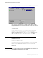
How To Access the Monitor and Server Revision Screen . . . . . . . 5-37
Troubleshooting the Installed Instrument . . . . . . . . . . . . . . . . . . . . . . . 5-37
Troubleshooting with Self-Test Alarm Messages
(When You Switch the Monitor On) . . . . . . . . . . . . . . . . . . . . . 5-38
Troubleshooting When There is No Message on the Screen . . . . . 5-39
Troubleshooting During/After a Software Upgrade . . . . . . . . . . . . . . . 5-39
Troubleshooting the Printer Connection . . . . . . . . . . . . . . . . . . . . . . . . 5-40
Tutorial for Troubleshooting the Instrument . . . . . . . . . . . . . . . . . . . . . 5-41
Answers to the Tutorial for Troubleshooting the Instrument. . . . . . . . . 5-42
Objectives. . . . . . . . . . . . . . . . . . . . . . . . . . . . . . . . . . . . . . . . . . . . . . . . 6-1
Concepts. . . . . . . . . . . . . . . . . . . . . . . . . . . . . . . . . . . . . . . . . . . . . . . . . 6-1
Warnings, Cautions and Safety Precautions . . . . . . . . . . . . . . . . . . . . . 6-2
Disassembly for the Monitor . . . . . . . . . . . . . . . . . . . . . . . . . . . . . . . . . 6-2
Removing the Battery . . . . . . . . . . . . . . . . . . . . . . . . . . . . . . . . . . . 6-2
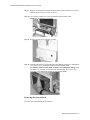
Removing the Power Supply . . . . . . . . . . . . . . . . . . . . . . . . . . . . . . 6-2
Removing the Chassis . . . . . . . . . . . . . . . . . . . . . . . . . . . . . . . . . . . 6-3
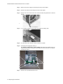
Removing the System Board . . . . . . . . . . . . . . . . . . . . . . . . . . . . . . 6-5
Removing the Wireless Assembly (for Monitors with Wireless LAN Interface only) 6-7
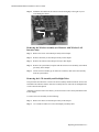
Removing the LCD Assembly and Backlight Tubes . . . . . . . . . . . 6-7
Removing the Connector Board . . . . . . . . . . . . . . . . . . . . . . . . . . . 6-9
Removing the Speaker . . . . . . . . . . . . . . . . . . . . . . . . . . . . . . . . . . 6-9
Refit Procedures for the Monitor . . . . . . . . . . . . . . . . . . . . . . . . . . . . . . 6-11
Refitting the System Board . . . . . . . . . . . . . . . . . . . . . . . . . . . . . . . 6-11
Refitting the LCD Assembly and Backlight Tubes . . . . . . . . . . . . 6-11
ix
Refitting the Connector Board . . . . . . . . . . . . . . . . . . . . . . . . . . . . .6-11
Refitting the Speaker . . . . . . . . . . . . . . . . . . . . . . . . . . . . . . . . . . . .6-11
Refitting the Power Supply . . . . . . . . . . . . . . . . . . . . . . . . . . . . . . . .6-11
Refitting the Wireless Assembly . . . . . . . . . . . . . . . . . . . . . . . . . . .6-12
Refitting the Chassis . . . . . . . . . . . . . . . . . . . . . . . . . . . . . . . . . . . . .6-12
Refitting the Battery . . . . . . . . . . . . . . . . . . . . . . . . . . . . . . . . . . . . .6-12
Disassembly Procedures for the Measurement Server Extension . . . . . .6-13
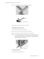
Removing the Front Cover . . . . . . . . . . . . . . . . . . . . . . . . . . . . . . . .6-13
Removing the Extension Bottom Cover . . . . . . . . . . . . . . . . . . . . . .6-13
Removing the CO2 Scrubber . . . . . . . . . . . . . . . . . . . . . . . . . . . . . .6-16
Removing the Infrared Lamp . . . . . . . . . . . . . . . . . . . . . . . . . . . . . .6-16
Removing the Pump . . . . . . . . . . . . . . . . . . . . . . . . . . . . . . . . . . . . .6-18
Refit Procedures for the Measurement Server Extension . . . . . . . . . . . .6-19
Refitting the CO2 Scrubber . . . . . . . . . . . . . . . . . . . . . . . . . . . . . . .6-19
Refitting the Infrared Lamp . . . . . . . . . . . . . . . . . . . . . . . . . . . . . . .6-20
Refitting the Pump . . . . . . . . . . . . . . . . . . . . . . . . . . . . . . . . . . . . . .6-21
Refitting the Extension Bottom Cover . . . . . . . . . . . . . . . . . . . . . . .6-21
Refitting the Front Cover . . . . . . . . . . . . . . . . . . . . . . . . . . . . . . . . .6-21
General Reassembly/Refitting Comments. . . . . . . . . . . . . . . . . . . . . . . .6-22
Following Reassembly. . . . . . . . . . . . . . . . . . . . . . . . . . . . . . . . . . . . . . .6-22
Answers to Tutorial for Repairing the Instrument. . . . . . . . . . . . . . . . . .6-24
Objectives . . . . . . . . . . . . . . . . . . . . . . . . . . . . . . . . . . . . . . . . . . . . . . . .7-1
What’s New in this Service guide . . . . . . . . . . . . . . . . . . . . . . . . . . . . . .7-2
Parts History . . . . . . . . . . . . . . . . . . . . . . . . . . . . . . . . . . . . . . . . . . .7-2
Compatibility Matrix - Release A to Release B . . . . . . . . . . . . . . . .7-3
Compatibilities and Incompatibilities . . . . . . . . . . . . . . . . . . . . . 7-3
List of Parts . . . . . . . . . . . . . . . . . . . . . . . . . . . . . . . . . . . . . . . . . . . . . . .7-4
Exchange Parts List . . . . . . . . . . . . . . . . . . . . . . . . . . . . . . . . . . . . .7-8
Appendix A Main Sales and Support Offices A-1
x
1
Introduction to the Instrument
Objectives
In order to meet this chapter’s goals, you should become familiar with the Instrument and be
able to identify the Instrument’s parts in some detail. As well, you should be able to explain
how the Measurement Server and Measurement Server Extensions acquire and process
physiological measurements and how the Monitor displays the data.
The following topics are covered in this chapter:
• Introducing the Instrument Components
• Section 1 - Monitor Description
• Functional Description of the Monitor Hardware
• Section 2 - Measurement Server Description and Features
• Measurement Server Theory of Operation
• Functional Description of the Measurement Server Hardware
• Electrocardiogram/Respiration (ECG/Resp) Measurement
• Non-invasive Blood Pressure (NBP) Measurement
• Arterial Oxygen Saturation and Pleth (SpO /PLETH) Measurement
2
• Temperature and Invasive Blood Pressure (Temp/Press) measurement
• Section 3 - Measurement Server Extensions Description and Features
• M3015A Measurement Server Extension Theory of Operation
• Functional Description of the M3015A Measurement Server Extension Hardware
• Sidestream CO Measurement
2
• M3016A Measurement Server Extension Theory of Operation
• Functional Description of the M3016A Measurement Server Extension Hardware
• Mainstream CO Measurement
2
Concepts
The following section contains information that you need to understand in order to
competently maintain and repair an M2, M3 or M4 Monitor and Measurement Server with or
without a Measurement Server Extension.
7KHRU\RI
2SHUDWLRQ
The theory of operation for a component describes the processing of signals
within the component.
)XQFWLRQDO
'HVFULSWLRQ
The functional description of a component uses a diagram of the circuitry
followed by short, written explanations of the component circuitry.
Introduction to the Instrument
1-1
M3000A/M3046AM3015A/M3016A Service Guide
Introducing the Instrument Components
The M3000A and M3000A #D06 Multi-Measurement Servers, the M3015A and M3016A
Multi-Measurement Server Extensions and the M3046A Compact Portable Patient Monitor
form a flexible, portable, battery, or line-powered patient Monitor. (Note: The combined
devices are referred to as the ,QVWUXPHQW in this manual.)
The M3000A Multi-Measurement Server acquires the physiological signals ECG, respiration,
invasive and non-invasive blood pressure, oxygen saturation of the blood, and temperature.
The M3000A #D06 Multi-Measurement Server acquires the physiological signals ECG,
respiration, non-invasive blood pressure, and oxygen saturation of the blood. The signals are
converted into digital data, and processed before being communicated to the Monitor. (Note:
The server device is referred to as the Measurement Server or simply the 6HUYHU in this
manual. As well, unless specified, documentation intended for the M3000A Server is also
intended for the M3000A #D06 Server.)
The M3015A Measurement Server Extension acquires the physiological signals invasive
blood pressure, temperature and partial pressure of carbon dioxide (via sidestream sampling).
The M3016A Measurement Server Extension acquires the physiological signals invasive
blood pressure, temperature and partial pressure of carbon dioxide (via mainstream
sampling).
When using the M3015A and M3016A, all the signals are converted into digital data, and
processed before being communicated to the Monitor. (Note: Server extension devices are
referred to as the Measurement Server Extensions or simply ([WHQVLRQV in this manual.)
The M3046A Compact Portable Patient Monitor receives the processed data from the
Measurement Server and the Measurement Server Extension, examines it for alarm
conditions, and displays it. The Monitor also provides operating controls for the user, and
interfaces to other devices. (Note: This monitoring device is referred to as the Monitor in this
manual.)
1-2 Introduction to the Instrument
M3000A/M3046A/M3015A/M3016A Service Guide
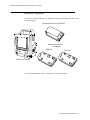
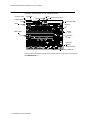
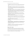
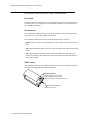
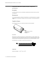
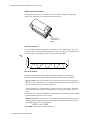
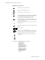
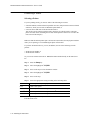
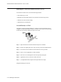
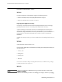
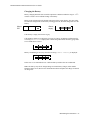
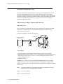
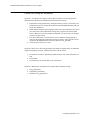
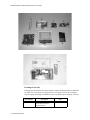
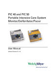
Instrument Components
The Monitor, the Measurement Server, and Measurement Server Extensions are shown in the
following diagram.
Measurement Server (M3000A)
Measurement Server
Extensions
M3016A
M3015A
Monitor (M3046A)
For functional descriptions of these components, see later in this chapter.
Introduction to the Instrument 1-3
M3000A/M3046AM3015A/M3016A Service Guide
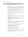
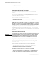
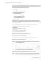
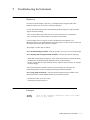
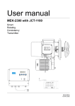
A Quick Description of the Monitor
)URQW3DQHO.H\V
Alarm
Indicator
Alarm Suspend
Key & Indicator
Alarm
Silence/Reset Key
Silence
Reset
Suspend
Setup
Key
Setup
On Off/Standby
On
Off/Standby
Main Screen
Key
Main
Screen
AC Power
Battery
Battery LED
On Off/Standby LED
Green when Monitor is on
AC Power LED
Green when AC Power
is Connected
Green- Battery full (>95%)
Yellow- Battery charging
Blinking Red- Battery empty
)URQWRI0RQLWRU
Menu Highlight
Up Key
ECG Out/
Marker In (≤12V)
Menu Enter
Key
Equipotential
Grounding Post
Menu
Highlight
Down Key
AC Power
Connector
(100 to 240Vac
50/60Hz)
Battery
Compartment
TouchStrips
Infrared Printer Port
1-4 Introduction to the Instrument
M3000A/M3046A/M3015A/M3016A Service Guide
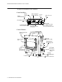
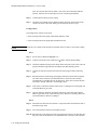
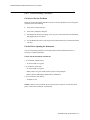
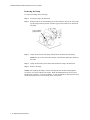
%DFNRI0RQLWRU
Locking Mechanism for
the Measurement Server
Connector to
the Measurement
Server (≤48V)
Mounting Plate
Protective earth
connector point
for additional display
Catches for
attaching the
Measurement
Server
LAN/SoftwareUpdate
Connector (≤5V)
Connector for an additional
display (VGA Interface) (≤3.3V)
Nurse Call Relay
Connector (≤36V)
Introduction to the Instrument 1-5
M3000A/M3046AM3015A/M3016A Service Guide
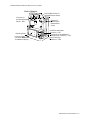
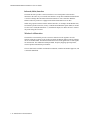
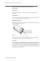
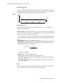
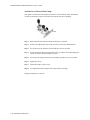
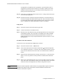
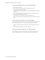
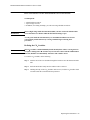
A Quick Description of the Measurement Server
2YHUYLHZRIWKH0$0HDVXUHPHQW6HUYHU
Start/Stop
(for NBP)
Connector
to Monitor or
Measurement
Server Extension
Zero
for Press
(Stat key
for option #D06)
Measurement
Connectors
Alarm
Silence/Reset
0$0HDVXUHPHQW&RQQHFWRUV
Press
Temp
SpO2
ECG/Resp
Note:
Press and Temp cannot
be used at the same time.
NBP
0HDVXUHPHQW&RQQHFWRUVIRUWKH0$'0HDVXUHPHQW6HUYHU
SpO2
ECG/Resp
1-6 Introduction to the Instrument
NBP
M3000A/M3046A/M3015A/M3016A Service Guide
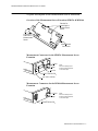
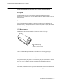
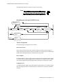
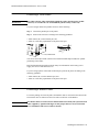
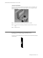
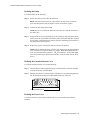
A Quick Description of the Measurement Server Extension
2YHUYLHZRIWKH0HDVXUHPHQW6HUYHU([WHQVLRQV0$0$
Catches for
attaching the
Measurement
Server
Connectors
to Monitor &
Measurement
Server
Measurement
Connectors
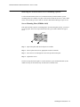
0HDVXUHPHQW&RQQHFWRUVIRUWKH0$0HDVXUHPHQW6HUYHU
([WHQVLRQ
Press
Temp
gas inlet
Note:
Press and Temp cannot
be used at the same time
on the same part.
SIDESTREAM CO2
gas outlet (exhaust)
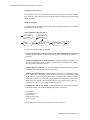
0HDVXUHPHQW&RQQHFWRUVIRUWKH0$0HDVXUHPHQW6HUYHU
([WHQVLRQ
Press
Temp
Note:
Press and Temp cannot
be used at the same time
on the same part.
MAINSTREAM CO 2
Introduction to the Instrument 1-7
M3000A/M3046AM3015A/M3016A Service Guide
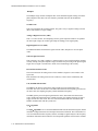
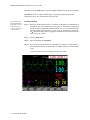
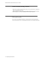
A Quick Description of the Main Screen
Monitor Label
QuickSet
Time
4XLFN6HW
$GXOW
6&+/$&.$1'5($6
Wave
Non-Paced Symbol
Patient Size
Patient Name
,,
$ODUPV6XVSHQGHG
6LQXV5K\WKP
P9
6S2 3OHWK
Wave Label
$%3
$%3 1%3
$XWR
PLQ
PHDQ
1%367$7
6WRS$OO
=HUR
39&
V\V
Numeric
Alarm
Limits
Numeric
Label
5HVS
6723
6WDUW6WRS
Alarm Message
+5
Alarm Off
Symbol
(measurement)
6WRUH6FUHHQ 7UHQGV
SmartKey Label/Icon
You can return to the display with the waves and the numerics at any time by pressing the
blue 0DLQ6FUHHQ key
1-8 Introduction to the Instrument
M3000A/M3046A/M3015A/M3016A Service Guide
Theories of Operation and Functional Descriptions
The theories of operation and functional descriptions are presented in three sections:
6HFWLRQ
Monitor Description
•M3046A Monitor Theory of Operation
•Functional Description of the Monitor Hardware
6HFWLRQ
M3000A Measurement Server Description and Features
•Measurement Server Theory of Operation
•Functional Description of the Measurement Server Hardware
•Electrocardiogram/Respiration (ECG/Resp) Measurement
•Non-invasive Blood Pressure (NBP) Measurement
•Arterial Oxygen Saturation and Pleth (SpO2/PLETH) Measurement
•Temperature and Invasive Blood Pressure (Temp/Press) measurement
6HFWLRQ
Measurement Server Extensions Description and Features
•M3015A Measurement Server Extension Theory of Operation
•Functional Description of the M3015A Measurement Server Extension
Hardware
•Sidestream CO2 Measurement
•M3016A Measurement Server Extension Theory of Operation
•Functional Description of the M3016A Measurement Server Extension
Hardware
•Mainstream CO2 Measurement
Introduction to the Instrument 1-9
M3000A/M3046AM3015A/M3016A Service Guide
Section 1 - Monitor Description
The M3046A Patient Monitor is a small size, lightweight monitor with a TouchBar human
interface. The monitor has a color display with a wide viewing angle, and excellent visibility
from a distance, so that data can easily be recognized. For applications where a larger display
is required, an additional display can be connected to the monitor via the standard VGA
output.
Trend data, and manual and automatic event storage, together with a range of report styles are
available for tracking and documenting the patient’s progress.
The Monitor receives the processed data from the Measurement Server and the Measurement
Server Extension, examines it for alarm conditions, and displays it. The Monitor also
provides operating controls for the user, and interfaces to other devices.
1-10 Introduction to the Instrument
M3000A/M3046A/M3015A/M3016A Service Guide
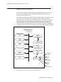
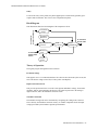
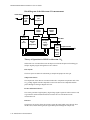
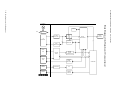
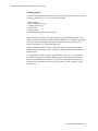
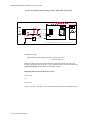
Monitor Theory of Operation
The Monitor receives data passed from the patient through the Measurement Server and,
where present, the Measurement Server Extension. The Monitor displays the data in
numerics and waves on the screen.
The Monitor is prepared with a number of software modules, which communicate with each
other as shown in the diagram below. The Monitor software communicates with the
Measurement Server and, where present, the Measurement Server Extension via a normal
local area network (LAN) link. Data from the Monitor can be output to a printer via an
infrared serial link or via the LAN connector to a central print server. The Monitor can
communicate with an Agilent Information Center via the LAN Connector (wired network) or
via the Wireless LAN Assembly (wireless network) when the appropriate options are present.
0&386\VWHP
Inter-process
Communications
Communication
Module
Printer
Manager
Trend
Module
Events
Module
IrDA
Communication
Display
Controller
ADT Module
Support
Services
Alarm
Manager
Display and
Operator
Interface
Operating
controls
LEDs
HIF
Controller
Battery
controller
Alarm
Relay
Loudspeaker
Each of these modules is described in the following sections.
Introduction to the Instrument 1-11
M3000A/M3046AM3015A/M3016A Service Guide
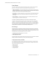
'LVSOD\DQG8VHU,QWHUIDFH6RIWZDUH0RGXOH
The Display and User Interface Software displays measurement data and status information
on the color LCD display, and processes the operator inputs from the HIF Controller. The
interface consists of the following sub-modules:
•
•
•
•
Screen Configuration.
Numerics and Wave Presentation.
Key and TouchStrip Processing.
Alarm and Status Presentation.
$ODUP0DQDJHU6RIWZDUH0RGXOH
The visual and audible alarms generated by the Measurement Server, the Measurement
Server Extension or by the Monitor software modules are assigned priorities by the Alarm
Manager. The Alarm Manager also:
•
•
•
•
Monitors the “alarm suspended”, “alarm silence” and “alarm reminder” functionality.
Manages alarm latching (alarms remain in effect until reset or turned off by the user).
Triggers the Nurse Call Relay.
Generates alarm event triggers for any user-defined trigger conditions.
$GPLW'LVFKDUJH7UDQVIHU$'76RIWZDUH0RGXOH
This module maintains the patient’s demographics and controls the upload of trend data from
the Measurement Server and the Measurement Server Extension. It allows the user to:
• Admit a new patient.
• Transfer a patient to another Monitor.
• Discharge a patient.
7UHQG6RIWZDUH0RGXOH
This module manages a trend database. It stores physiological values from the Measurement
Server and from the Measurement Server Extension in two separate databases, a short-term
and a long-term database. The contents of these databases is battery-buffered, so that no data
is lost in the event of a power failure.
(YHQWV6RIWZDUH0RGXOH
The events software module allows the user to take snapshots of the Monitor state and store
them for later viewing or printing.This can be done automatically, triggered by alarms, if the
monitor is configured appropriately. The types of data that can be captured are as follows:
• All physiological values.
• All current alarms.
• The last 20 seconds of wave data.
1-12 Introduction to the Instrument
M3000A/M3046A/M3015A/M3016A Service Guide
3ULQWHU0DQDJHU
The printer manager formats and prints the following reports on either a locally attached
printer or a remote printer connected to the Instrument via the M3 Print Server:
• 7DEXODU7UHQG5HSRUW—The printer manager takes raw data from the trend module and
generates a formatted report. The user can specify whether to print short-term or long-term
trend data, and the period for which the data should be printed.
• (YHQW5HSRUW—The printer manager takes raw data from the event module and generates a
formatted event report. The user can specify a manual event, an alarm event, or a print
screen report.
• (YHQW/LVW5HSRUW—The printer manager takes the raw event list data from the events
module and generates a formatted event list report.
See Chapter 2, Installing the Instrument for more details on connecting to a printer.
A number of drawing functions support the printer manager and provide it with graphics
capabilities. The output from the printer manager is in PCL (Printer Command Language)
format, and is fed to the locally attached printer, which is connected via an infrared data link,
or to a remote printer. If the link to the printer is interrupted for a certain time, the printer
manager displays a prompt of the color LCD display, notifying the user.
,U'$0DQDJHU
The IrDA manager is responsible for sending raw data to the local printer in a format that
complies with the IrDA (Infrared Data Association) standard. The IrDA manager provides a
general printer device interface to the printer manager, and maps the general printer services
to the IrDA protocol. The general printer services are as follows:
• Establishing and terminating the printer connection.
• Transferring data to the printer.
• Retrieving the printer status.
The IrDA manager feeds the printer status (time out, paper out, and so on) back to the printer
manager, which in turn notifies the user of any errors in the print process.
&RPPXQLFDWLRQ6RIWZDUH0RGXOH
The communication module maintains a data link between the Monitor, the Measurement
Server and the Measurement Server Extension, and controls the exchange of data between
them. This data includes the following:
•
•
•
•
Measurement data.
status information.
Control information.
Configuration data.
Introduction to the Instrument 1-13
M3000A/M3046AM3015A/M3016A Service Guide
6XSSRUW6HUYLFHV
The support services software module contains miscellaneous functions that both the
Monitor, the Measurement Server and the Measurement Server Extension require. These
functions are as follows:
•
•
•
•
Date and Time.
Settings Handler.
Status Revision and Display.
Heart Rate Selector.
1-14 Introduction to the Instrument
M3000A/M3046A/M3015A/M3016A Service Guide
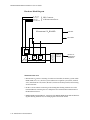
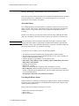
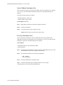
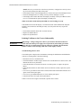
Functional Description of the Monitor Hardware
The Monitor receives data from the Measurement Server and Measurement Server Extension
via the Server-to-Monitor link bar and presents this data on the color LCD display. The
following block diagram shows the main functional areas.
Alarm
LAN
Relay VGA (Network)
&RQQHFWRU
%RDUG
6 Pin
Connector
AC
Vbat,
I2C
48V,
AC present
$&
3RZHU6XSSO\
Optional
6PDUW%DWWHU\
5 Pin
Connector
Optional
AC
Vbat 48V present
:LUHOHVV/$1
48 Pin
Connector
140 Pin
Connector
6\VWHP%RDUG
DC/DC Converter
48V current limiter
Battery charger
Processor (Battery
CPU System(360)
I2C
Serial Link
uP bus
Vbuf
SRL to
Measurement
Server
(Flash,SRAM,DRAM)
Controller)
48Vlim +5V
Ventilator
Fan
SRL
LAN
(M3000A)
I2C
HIF(83C552)
Rx,Tx
Display
Video
Controller
ECG Out/
Marker In
Controller
TouchStrip
Keys
Alarm LEDs
34 Wire
Flat Cable
PIC LEDs,Standby
(TouchStrip,Keys,Sound,
LEDs, Alarm Relay,
Battery)
ECG
Out
Video
40 Wire
Flat Cable
%H]HO$VVHPEO\
'LVSOD\$VVHPEO\
.H\ERDUG
LEDs:
X Bell(HIF)
Standby On/Off (PIC) On/Off(+5V)
AC Power(PIC) red alarm(HIF)
4 hardkeys(HIF)
yellow alarm(HIF)
Battery(PIC)
'LVSOD\$GDSWHU
%RDUG
31 Pin
Flex
/&'
'LVSOD\
6 Pin
cable
,QYHUWHU%RDUG
TouchStrips
,U'$
2x2 Pin
cable
%DFNOLJKW
(Infrared)
Introduction to the Instrument 1-15
M3000A/M3046AM3015A/M3016A Service Guide
The main functional areas are summarized in the following:
• 6\VWHP%RDUG²Comprising a 68360 Controller, the Memory System, the Video System,
LAN (network) connector link to Server, ECG-Out, Human Interface and DC/DC Converter.
• &RQQHFWRU%RDUG²Connecting the System Board to the AC Power Supply and battery.
The LAN (network) filter and connector, the VGA connector and the Alarm Relay Output
(Nurse Call) are located on the Connector Board. The Connector Board has a 48-pin connector to the System Board.
• 'LVSOD\$VVHPEO\²Comprising a 6.5 inch TFT color LCD display (including 2 backlight
tubes), the Display Adapter Board and the associated backlight inverter board (generates
the high voltage for the tubes). These parts are packed into a soft, rubber-based holder
(sometimes referred to as the FXVKLRQ). (Note: The LCD display uses WKLQILOPWHFKQRORJ\
and is sometimes referred to as a 7)7 display.)
The Display Assembly connects to the System Board via a 40-wire flat ribbon cable.
• %H]HO$VVHPEO\²Comprising the U-shaped TouchStrip, the Keyboard (which includes
operating keys, alarm LEDs, On/Off switch and AC and battery indicator LEDs), and the
IrDA Board (infrared printer interface).
The Bezel Assembly connects to the System Board via a 34-wire flat ribbon cable.
• 6SHDNHU²Connected to the System Board with a 2-wire cable. The loudspeaker provides
the audible output for alarms, and audible feedback when the user presses a manual control.
• $&3RZHU6XSSO\²Connected to the Connector Board to power the Instrument and/or
charge the battery depending on the operating mode.
• 6PDUW%DWWHU\²As an option, a standard, intelligent battery with an I2C interface to the
DC/DC controller.
• :LUHOHVV/$1$VVHPEO\² Comprising the Wireless LAN CPU Board and the radio frequency (RF) Board. The Wireless LAN Assembly connects to the System Board via a 140pin extension connector. The RF Board connects to the antenna, which is built into the
monitor handle via a coax cable.
9HQWLODWRU)DQ² Connected to the System Board with a 2-wire cable. The fan controls
the temperature inside the Monitor when the Wireless LAN option is installed.
Detailed descriptions are given in the following sections.
'LVSOD\9LGHR&RQWUROOHU
The Display Video Controller runs the software that controls the display. This software
processes the high level display command to generate and format the screen characters,
graphics, and wave plots, and also generates the video control signals for the LCD display.
The software continuously checks the functionality of the hardware in the Display Controller,
and issues an error indication in the event of a hardware malfunction.
1-16 Introduction to the Instrument
M3000A/M3046A/M3015A/M3016A Service Guide
+XPDQ,QWHUIDFH&RQWUROOHU
The Human Interface Controller (HIF) is the interface between the operator and the Monitor
itself. It monitors the operator controls and the Battery Controller, formats the data, and
routes it to the Display & Operator Controls Manager from which it receives commands and
status also. As well, the HIF controls the features listed below.
9LVXDO,QGLFDWRUV
The Instrument is fitted with the following front panel indicators:
• <HOORZ/('—This flashes in addition to the visual indication on the LCD display when a
yellow-alarm situation occurs (medium severity alarm).
• 5HG/('—This flashes in addition to the visual indication on the LCD display and the
audible tone from the loudspeaker when a red-alarm situation occurs (high severity alarm).
• &URVVHG%HOO/('²This is illuminated when all alarms have been suspended.
$ODUP5HOD\
In addition to the audible and visual alarms, an alarm relay is provided, which energizes
when an alarm condition occurs. This enables a remote alarm indicator (such as a Nurse Call)
to be connected to the device.
%DWWHU\&RQWUROOHU
The battery controller is the interface to the Smart battery. Signals from the battery inform the
battery controller of the most effective charging current with which to load the battery. Two
LEDs are mounted on the Battery Controller:
• %DWWHU\/('—This is illuminated green if the battery is fully charged and yellow if the
battery is charging. If the remaining battery-operating time is only 5 minutes, the LED
flashes red at a repetition rate of 1.5 flashes per second.
• $&/('—This is illuminated green when the power cord is connected and AC power is
available. Otherwise it is extinguished. The AC LED is fed directly from the AC power
supply.
For a detailed description of the battery, see chapter 3, “Maintaining the Instrument”.
(&*2XW0DUNHU,Q&RQWUROOHU
The ECG Out/Marker In Controller is the interface between the Monitor and any defibrillator
that might be connected. It converts a digital waveform signal received from the
Measurement Server ECG/Respiration module into an analog ECG signal, which it feeds to
the defibrillator in order to synchronize it. The ECG Out controller also processes the marker
information from the defibrillator and feeds the data back to the Measurement Server ECG/
Respiration measurement module.
Introduction to the Instrument 1-17
M3000A/M3046AM3015A/M3016A Service Guide
,QIUDUHG,U'$,QWHUIDFH
The IrDA interface provides a wireless interface to an external printer. This interface
functions in the same way as a normal serial interface except that a modulated infrared beam
is used to exchange data and status information instead of a wire connection. Both the
Monitor and some printers are equipped with infrared transmitter/receiver units.
When using a printer without a built-in infrared interface, for example, the HP DeskJet 420,
an infrared to parallel converter (Jet-Eye, orderable under M3080A Option #H05) is needed.
See the User’s Guide (M3046-9001C-1) , Installation chapter, for details on how to connect
the printer using this converter.
:LUHOHVV/$1,QWHUIDFH
The Wireless LAN interface provides a wireless connection to the Agilent LAN. The
Wireless LAN CPU connects to the wired LAN inside the Monitor and provides the software
drivers for the RF Board. The RF Board transforms wired LAN signals into 2.4 GHz signals
for transmission. The modulation technique FHSS, frequency hopping spread spectrum,
ensures optimum transmission performance.
The 2.4 GHz band is available worldwide for industrial, scientific and medical purposes, and
is called the ISM-band.
1-18 Introduction to the Instrument
M3000A/M3046A/M3015A/M3016A Service Guide
Section 2 - Measurement Server Description and Features
The Measurement Server is a highly flexible patient measurement unit, which is the base for
a variety of systems that enable easy customization to a hospital’s requirements. It provides a
subset of the most important patient measurements in a convenient, single part.
The Measurement Server is designed to Monitor patients in most critical and acute patient
care areas of the hospital. Used at the bedside, it is most commonly mounted to a Monitor. It
can also be mounted separately on a bed or a roller stand.
0$0HDVXUHPHQW6HUYHU6WDQGDUG3DFNDJH
The Measurement Server (M3000A) standard package includes:
• Measurements of ECG/Resp, NBP, SpO2, Press, and Temp,
• Signal and alarm processing.
0$0HDVXUHPHQW6HUYHU1RQLQYDVLYH0HDVXUHPHQWV
3DFNDJH
The Measurement Server (M3000A #D06) optional package includes:
• Measurements of ECG/Resp, NBP, and SpO2,
• Signal and alarm processing.
)HDWXUHV
The Measurement Server has the following general features:
'DWD0DQDJHPHQW
The Measurement Server features Patient Data Management. This consists of continuous 4hour storage of patient-related measurement information. This allows you to do the
following:
•
•
•
•
Manage patient information,
View patient data in tabular form via the Monitor,
Print patient information reports via the Monitor,
Transfer data between Monitors.
6HWWLQJV7UDQVIHU
The Measurement Server can be transported from one Monitor to another and still keep its
measurement settings. The settings (such as alarm limits) are stored inside the server. This
behaviour permits fast and easy transport.
Introduction to the Instrument 1-19
M3000A/M3046AM3015A/M3016A Service Guide
$ODUPV5HVHW
The Silence/Reset key on the Measurement Server allows you to silence alarm tones, while
retaining visual alarm messages (depending on your Monitor’s configuration).
6HUYHUWR0RQLWRU/LQN%DU
A single connector (sometimes referred to as the 6HUYHUWR0RQLWRU connector or link bar)
allows quick and easy connection to a Monitor. This allows the Monitor to show waves and
alarms from the Measurement Server.
The interface subsystem consists of the physical interface to the Monitor or the Measurement
Server Extension and controlling software.
Digitized patient information transmitted over the link bar may be waves (for ECG, pressure,
respiration, pleth); numeric information (for heart rate/pulse, pressure values, SpO2 and
respiration rate); or alert information (for alarms and assorted status information).
For Service Procedures there is a special Service Link Bar, which is used in place of the
standard Link Bar.
1-20 Introduction to the Instrument
M3000A/M3046A/M3015A/M3016A Service Guide
Measurement Server Theory of Operation
The Measurement Server is prepared with software divided into four major conceptual layers.
The Measurement Server software communicates with the Monitor via a normal local area
network (LAN) link. The four conceptual layers of the Server software are divided as
follows:
• 7KH)LUVW/D\HU—This consists of the operating system which passes messages between
the various major sections of the software. As well, the operating system performs system
initialization, background error checking, and checking while the software is running.
• 7KH6HFRQG/D\HU—This consists of the monitoring management system. This layer
includes the following software:
• Alarm software.
• Record software.
• Trend database software.
• Heart rate software.
• 7KH7KLUG/D\HU—This consists of the interface management and interface controllers.
This layer contains the date/time, and Server-to-Monitor link managers.
• 7KH)RXUWK/D\HU—This consists of the monitoring algorithms and software to acquire the
physiological signals.
Introduction to the Instrument 1-21
M3000A/M3046AM3015A/M3016A Service Guide
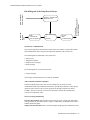
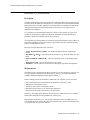
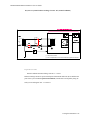
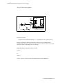
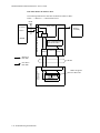
Functional Description of the Measurement Server Hardware
The Server receives information signals (such as ECG, etc.) from the patient, performs some
data processing, then transmits the data to the Monitor via the Server-to-Monitor link bar.
The following block diagram shows the main functional components of the Measurement
Server.
CPU Board
Front End Board
6Vac
From
Patient
ECG/Resp Front End
SpO2 Front End
6Vac
Floating /
Non-Floating
Isolation
CPU System
(68360, Flash-ROM
SRAM, DRAM,
ASIC, RTC,...)
-6Vac
14Vac
From
Patient
NBP
Pneumatic
Assembly
12V
Link Bar
Serial Link
Press/Temp Front End
3.3V
DC/DC
5V
+12V
Converter
-12V
Board 3.3V (Buffd.)
48V
78kHz
To/From
Monitor
48V
78kHz
Pneumatic
Power Switches
+12V -12V
NBP
A/D
Converters
The main functional areas are summarized below.
&38%RDUG—Consisting of a 68360 Controller, the Memory System (Flash ROM, SRAM,
DRAM, ASIC, RTC, etc.), the NBP A/D Converters, and a connector link to a Monitor or
an Extension.
• )URQW(QG%RDUG—Consisting of the ECG/Resp Front End, the SpO2 Front End, the Press/
Temp Front End and the Floating/Non-Floating Isolation area all feeding signals to the
CPU Board.
• 1%33QHXPDWLF$VVHPEO\²Connecting to the DC/DC Converter Board, the Pneumatic
Power Switches housed in the DC/DC Converter Boardand to the NBP A/D Converters.
• '&'&&RQYHUWHU%RDUG²Connecting to the Floating/Non-Floating Isolation area on the
Front End Board, to the NBP Pneumatic Assembly and to the CPU System.
1-22 Introduction to the Instrument
M3000A/M3046A/M3015A/M3016A Service Guide
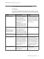
Electrocardiogram/Respiration (ECG/Resp) Measurement
'HVFULSWLRQ
The Measurement Server has a three-channel electrocardiogram and respiration
measurement. It is designed to be used with adult, neonatal, or pediatric patients in ICU and
OR environments.
0HDVXUHPHQWV
The ECG/Resp measurement produces continuous real-time waves for both cardiac and
pulmonary activity. It also generates numerics for the average heart rate (HR), derived from
the ECG, and for the respiration rate (RR).
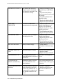
(&*5HVS)HDWXUHV
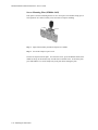
This illustration shows the user controls and connectors for the ECG/Resp.
This standard 12-pin
connector will accept
either a 3-lead or a 5-lead
ECG cable.
Features of the ECG/Resp measurements are described in the following paragraphs.
(&*0RGHV
The QRS complexes are detected automatically.
In non-paced mode, no pace pulses are expected and no pace pulse rejection occurs. In paced
mode, pace pulses of channel 1 and 2 are annotated with a small dash on the screen.
5HVS0RGHV
In auto mode, the Monitor measures respiration and adjusts the detection level automatically.
In manual mode, the user sets the detection level for measuring respiration.
Introduction to the Instrument 1-23
M3000A/M3046AM3015A/M3016A Service Guide
6DIHW\
To ensure the safety of the patient, the patient-applied parts are isolated from ground by
optical isolators and a transformer. The circuit is also encapsulated in plastic.
%ORFN'LDJUDPRIWKH(&*5HVS
C
RA
LA
LL
RL
ECG
Electrodes
From
Patient
Input
Protection
Network
ECG
ASIC
CPU
ROM/RAM
To/From
System CPU
Bridge &
Amplifier
Demodulator
Respiration
Excitation
Current
Source
7KHRU\RI2SHUDWLRQ
As ECG and Resp signals pass from the patient to the Monitor, they progress through stages
corresponding to the logical sections of the circuit, as shown in the block diagram. Circuitrelated faults can generally be isolated to one of the stages.
7UDQVGXFHU
Signals are received through patient electrodes and lead cables via the input connector.
,QSXW3URWHFWLRQ1HWZRUN
The Input Protection Network and ESU filter eliminate extraneous signals. This protects the
rest of the circuitry from defibrillator voltages, high frequency interference signals, and
electrostatic discharges.
(&*$6,&
The signals are processed by the ECG Application-Specific Integrated Circuit (ECG ASIC)
which has an input amplifier with a fixed gain for each of the four electrodes. They are then
passed to a digital-to-analog converter (D/A Converter) for offset compensation and then to
an analog-to-digital converter (A/D Converter). The input/output logic (which is controlled
from the CPU) controls the analog-to-digital conversion and reads out the digitized ECG
data. The CPU communicates with the ECG ASIC via a built-in serial link.
To prevent interference from the 50/60Hz power line, the common mode signal is used to
drive the right leg (RL) drive amplifier. The output from the amplifier is then returned to the
patient via the RL electrode.
1-24 Introduction to the Instrument
M3000A/M3046A/M3015A/M3016A Service Guide
([FLWDWLRQ&XUUHQW6RXUFH
The excitation current source feeds a small current into the right arm and left leg electrodes.
This results in a voltage drop between the right arm and left leg which is proportional to the
thorax impedance.
%ULGJH$PSOLILHU
The bridge subtracts an offset from the voltage between right arm and left leg. The amplifier
amplifies the remaining signal.
7KH&HQWUDO3URFHVVLQJ8QLW&38
ECG ASIC
Controller
Pace Pulse
Detection
Data
Acquisition
Wave Processing
& Filtering
System CPU
Communication
System
CPU
The CPU performs the following functions:
• &RQWUROVWKH(&*$6,&DQGVWRUHV$6,&VSHFLILFFDOLEUDWLRQDQGHUURUORJGDWD This
initializes the intended ASIC configurations such as gain, A/D sampling rate, and DAC
operation.
• $FTXLUHVWKHGLJLWL]HG(&*DQG5HVSVLJQDOVDigitized ECG signals are used to calculate 3 ECG leads which are then passed on to the Pace Pulse detecting software, and the
wave processing and filtering software.
• 3HUIRUPV(&*ZDYHILOWHULQJThe waves are digitally filtered and scaled then passed to
the software that communicates with the system CPU.
• 3HUIRUPVSDFHSXOVHGHWHFWLRQA digital high-pass filter acts as a slope detector for the
received ECG waves. The output of the slope detector is fed into two comparators comparing the signal to a positive and negative threshold. The output of the comparators indicate
the absence or presence of a pace pulse. The threshold of the comparators is moving and
adapts itself to the amount of noise present in the ECG wave. Detected pace pulses are
communicated to the wave processing and filtering software.
• &RPPXQLFDWHVZLWKWKHV\VWHP&38Communication is via a serial, bi-directional data
link. The ECG/Resp CPU sends the following data to the system CPU:
•
•
•
•
•
3 ECG waves,
A respiration wave,
Pace pulse data,
INOP messages, and
status messages.
The ECG/Resp CPU receives control messages from the system CPU.
Introduction to the Instrument 1-25
M3000A/M3046AM3015A/M3016A Service Guide
Non-invasive Blood Pressure (NBP) Measurement
'HVFULSWLRQ
The Measurement Server has a non-invasive blood pressure measurement for the Monitor
monitoring device. It is designed to be used with adult, paediatric, or neonatal patients, in
ICU and OR environments.
0HDVXUHPHQWV
The measurement produces numerics for the systolic, diastolic, and mean blood pressure
values.No wave is associated with this measurement.
Three different methods can be used to obtain the measurements, as follows:
• 0DQXDO²For each request, one measurement of systolic, diastolic, and mean pressures is
taken.
• $XWR²Repeated measurements of the three values are taken at timed intervals specified by
the user.
• 6WDW²Measurements of the three values are taken immediately and repeatedly over a
period of five minutes. This method uses a faster measurement procedure but produces a
less accurate reading.
1%3)HDWXUHV
This illustration shows the user controls and connector for the measurements. The parts are
described in the paragraphs following the illustration.
6WDUW6WRS6WDW.H\
A single-press key, used to start
or stop a manual measurement,
or start an automatic measurement cycle.
A standard NBP connector
connects to the cuff.
1-26 Introduction to the Instrument
M3000A/M3046A/M3015A/M3016A Service Guide
1%30RGHV
The measurement offers adult, pediatric, and neonatal modes.
The following table lists the cuff inflation limits for each mode.
0RGH
)LUVW,QIODWLRQ
6XEVHTXHQW,QIODWLRQV
$ERYH6\VWROLF3UHVVXUH
6WDW0RGH
Adult
165
25
15
Pediatric
130
20
15
Neonatal
100
15
15
The following table lists the measurement ranges for each mode.
0RGH
6\VWROLF
'LDVWROLF
0HDQ
Adult
30 - 270
10 - 245
20 - 255
Pediatric
30 - 180
10 - 150
20 - 160
Neonatal
30 - 130
10 - 100
20 - 120
6DIHW\
The following table lists the maximum limits that ensure patient safety.
0RGH
0D[LPXP
0HDVXUHPHQW7LPH
0D[LPXP7LPH
3UHVVXUH
2YHUSUHVVXUH
0D[LPXP
Adult
180 seconds
180 seconds for
pressure > 15
mmHg
300 mmHg for > 2
seconds
Pediatric
180 seconds
180 seconds for
pressure > 15
mmHg
300 mmHg for > 2
seconds
Neonatal
90 seconds
90 seconds for pressure > 5 mmHg
150 mmHg for > 2
seconds
If any one of these safety limits is violated, an INOP is generated and the valve opens.
Introduction to the Instrument 1-27
M3000A/M3046AM3015A/M3016A Service Guide
%ORFN'LDJUDPIRU1%3
U
H
O
O
R
U
W
Q
R
F
R
U
F
L
$
'
$
'
$6,&
0
3
3
0
$
0
$
(
5
3
(
5
3
(
5
8
6
6
(
5
3
3
0
8
3
(
5
8
6
6
(
5
3
5
2
6
1
(
6
)
)
8
&
1-28 Introduction to the Instrument
(
5
8
6
6
(
5
3
5
2
6
1
(
6
1
2
,
7
$
/
)
(
'
0
(
7
6
<
6
M3000A/M3046A/M3015A/M3016A Service Guide
&RPSRQHQWV
The following components carry out the major signal processing functions within the
measurement.
3UHVVXUH3XPS—Inflates the cuff to preset limits, once or repeatedly, depending on the
measurement method used.
3UHVVXUH6HQVRU—Measures cuff pressure using solid-state technology.
2YHUSUHVVXUH6DIHW\6\VWHP²Triggers alerts at given pressures and time limits, and
deflates the cuff.
%DQGSDVV)LOWHU—Extracts arterial pressure oscillations from the cuff pressure.
'HIODWLRQ6\VWHP—Automatically deflates the cuff at steps of a given magnitude.
7KHRU\RI2SHUDWLRQ
As NBP signals pass from the patient to the Monitor, they progress through stages
corresponding to logical sections of the circuit, as shown in the block diagram. Circuitrelated faults can generally be isolated to one of the stages.
$FTXLVLWLRQ²Signals from the patient are received by the pressure sensor through the
cuff, which is connected to the circuit by a single tube. The cuff is inflated, deflated, and
monitored by a pump, deflation system, and safety system controlled by a microprocessor.
a.
b.
&XII,QIODWLRQ²During the initial cuff inflation, the cuff is inflated by the pressure
pump to a set pressure which is determined by the patient size. Thereafter the cuff is
inflated by the pressure pump to a cuff pressure above the patient’s systolic pressure.
Depending on the measurement method used, inflation occurs once or repeatedly.
When the cuff pressure is greater than the systolic pressure, the artery is occluded;
the pressure sensor then detects only the cuff pressure.
&XII'HIODWLRQ²Cuff pressure is automatically released by the deflation system in
steps until the artery is only partially occluded. At that point, measurement and
processing of arterial pressure oscillations begin and continue as the cuff pressure is
progressively released.
'HWHFWLRQ²The arterial pressure oscillations are superimposed on the cuff pressure.
They are extracted from the cuff pressure by a digital bandpass filter in the microcontroller.
0HDVXUHPHQW²As the cuff is deflated, the magnitude of the oscillations as a function of
cuff pressure increases until the mean arterial pressure is reached. When cuff pressure
falls below the mean arterial pressure, oscillation magnitude begins to decrease.
The systolic and diastolic blood pressure values are deduced from the oscillometric signal by extrapolation. Differences in the results with the standard stethoscope method can
be expected. The NBP accuracy complies with AAMI SP-10.
Introduction to the Instrument 1-29
M3000A/M3046AM3015A/M3016A Service Guide
Arterial Oxygen Saturation and Pleth (SpO2/PLETH)
Measurement
'HVFULSWLRQ
The Measurement Server has a pulse, arterial oxygen saturation, and plethysmogram
measurement.
0HDVXUHPHQWV
The measurement produces numerics for the arterial oxygen saturation value and the pulse
rate, along with a real-time wave for the plethysmogram.
6S23/(7+)HDWXUHV
This illustration shows the user controls and connector for the SpO2/PLETH. The parts are
described following the illustration below.
This is a standard 8-pin
connector for use with an
SpO2/PLETH transducer.
6DIHW\
To ensure the safety of the patient, the patient-applied part is isolated from ground by optocouplers and a transformer. The circuit is also encapsulated in plastic.
3/(7+:DYH
The circuit automatically and continuously adjusts the size of the wave, which represents the
quality of the SpO2 measurement signals. Manual wave adjustments in this mode are not
possible. If the signal quality becomes weak, the wave becomes progressively smaller. If the
signal degrades below an acceptable level, the wave becomes flat and an INOP alarm results.
A poor signal may be caused by poor perfusion at the transducer site, or by the transducer; it
is QRWrelated to low oxygen saturation.
1-30 Introduction to the Instrument
M3000A/M3046A/M3015A/M3016A Service Guide
This illustration contains an example of a typical wave in SpO2.
3OHWK
%ORFN'LDJUDPRIWKH6S23/(7+&LUFXLW
7R)URP6S27UDQVGXFHU
Clipping
Detector
photo Photo
current Amplifier
LED
current
Rtype/
Rlambda
Bandpass
Variable
Gain
ADC
LED Current
Source
Digital
Signal
Processor
CPU
ROM/RAM
ASIC
7R)URP6\VWHP&38
Self-Test Signal
Generator
RCode
Measurement
7KHRU\RI2SHUDWLRQ
The signals progress through the circuit as follows:
/('&XUUHQW6RXUFH
This generates the LED current from a constant voltage provided by the power supply. A
bridge consisting of four transistors switches the LED current for driving the red and infrared
LEDs. These switching transistors are controlled by the SpO2 CPU.
3KRWR$PSOLILHU
The photo amplifier is an active input current to voltage converter. The input signal is filtered
by a low pass filter to eliminate higher frequencies generated, for example, by electro-surgery
units. Then the input current from the photo diode of the sensor is converted to a voltage.
&OLSSLQJ'HWHFWRU
A comparator detects clipping of the photo-amplifier signal caused by, for example, ambient
light. The clipping detection is connected directly to the SpO2 CPU to generate an INOP if
necessary.
Introduction to the Instrument 1-31
M3000A/M3046AM3015A/M3016A Service Guide
%DQGSDVV
The bandpass stage contains a bandpass filter for the modulated signals coming in from the
photo-amplifier. This filters out noise outside a passband centred on the modulation
frequency.
9DULDEOH*DLQ
This section amplifies the incoming signals. The gain is set by a digital to analog converter
(DAC) which allows 512 gain settings.
$QDORJWR'LJLWDO&RQYHUWHU$'&
This is a 12-bit converter. Oversampling is used to get the required resolution. To optimize
the ADC input voltage, the variable gain adapts accordingly to the signal quality.
'LJLWDO6LJQDO3URFHVVRU'63
The DSP demodulates and filters the signal from the ADC, and passes it on to the SpO2
ASIC.
6HOI7HVW6LJQDO*HQHUDWRU
This generates a wave that is similar to a patient signal. It is processed through the complete
circuitry starting at the photo amplifier stage. Just before the processing of the patient signal
begins, the test signal is switched on to check correct functioning of the circuitry.
5&RGH0HDVXUHPHQW&LUFXLW
This circuit measures the coding resistor of the transducer, digitizes it, and sends it to the
SpO2 CPU.
Each transducer has coding resistors in the connector, so that it can be identified by this
measurement.
&385205$0DQG$6,&
The $6,& is the interface between the digital signal processor and the SpO2 CPU.
The ASIC also acts as an interface to the ADC and contains all the frequency generators for
the ADC clock, the sampling frequency and the modulation frequency. .
The &38gets the processed SpO2 signal from the ASIC, and controls the LED current
source, the RCode measurement, the variable gain stage, the clipping detection, the power
supply, and the Self-Test circuit. The CPU also detects INOP and error information and
handles communication with the system CPU.
6S2$OJRULWKP
The6S2$OJRULWKP receives the demodulated and filtered red and infrared signals, and the
transducer coding information from the SpO2 measurement frontend. The red and infra-red
wave is transformed into the frequency domain. An adaptive signal analysis of the frequency
information eliminates artifact and noise from the patient signal that is then used to calculate
1-32 Introduction to the Instrument
M3000A/M3046A/M3015A/M3016A Service Guide
the SpO2 and Pulse numeric values.
The SpO2 algorithm also detects non-pulsatile or noisy signals, and generates the appropriate
INOPs.
The wave is communicated to the Monitor (via the operating system), the SpO2 and pulse
rate are communicated to the average calculation software, and INOPs are communicated to
the alarming software.
Introduction to the Instrument 1-33
M3000A/M3046AM3015A/M3016A Service Guide
Temperature and Invasive Blood Pressure (Temp/Press)
measurement
'HVFULSWLRQ
The Measurement Server has a measurement channel which can measure invasive pressure
RU temperature.
0HDVXUHPHQWV
The measurement produces a numeric for temperature; or a real-time pressure wave, together
with the pulse rate and numeric readings for the systolic, diastolic, and mean blood pressure
values.
7HPS3UHVV)HDWXUHV
This illustration shows the user controls and connector for the Temp/Press.
Connectors for use with a
Temp or a Press
transducer.
3UHVV:DYH
Blood pressure is depicted as a pressure wave with the numerics for systolic, diastolic, and
mean pressure values. The blood pressure shows the cycles of contraction and release within
the heart and the resultant pressure that is generated to move the blood through the vessels.
This illustration is an example of a typical invasive pressure wave.
7HPS0RGH
Measurement Range: -1 to 45oC (30 to 113oF)
1-34 Introduction to the Instrument
M3000A/M3046A/M3015A/M3016A Service Guide
6DIHW\
To ensure the safety of the patient, the patient-applied part is isolated from ground by optocouplers and a transformer. The circuit is also encapsulated in plastic.
%ORFN'LDJUDP
7RDQGIURP
SUHVVXUHWUDQVGXFHU
This illustration shows the block diagram of the Temp/Press circuit.
7RDQGIURP
7HPSHUDWXUH
6HQVRU
Excitation
Voltage
Transducer
Detection
Input Protection
Network
A/D
Converter
CPU
ROM/RAM
7RDQGIURP
6\VWHP&38
Resistor
Array
Current
Source
7KHRU\RI2SHUDWLRQ
The signals progress through the circuit as follows:
([FLWDWLRQ9ROWDJH
This supplies 5VDC to a connected transducer. If a short circuit is detected by this circuit, the
CPU switches the voltage source off (to reduce power consumption).
,QSXW3URWHFWLRQ1HWZRUN
This provides protection for the rest of the circuit against defibrillator voltage, electrostatic
discharge, and any electromagnetic interference. The signal is passed on to the analog to
digital converter, and to the transducer detection circuit.
7UDQVGXFHU'HWHFWLRQ
The transducer being used can be determined by recognising the coding in the connector.
This is done by the transducer detection circuitry. A window comparator checks the input
voltages provided by the transducer against specified limits.
Introduction to the Instrument 1-35
M3000A/M3046AM3015A/M3016A Service Guide
&XUUHQW6RXUFH
The current source generates a constant current for the resistor array that is used to measure
the temperature.
5HVLVWRU$UUD\
The constant current is fed through four resistors in series: A test resistor, the externally
connected temperature probe, a gain calibration resistor, and an offset resistor. The voltage
drop across each resistor is sequentially measured and digitized. The CPU controls the
measurement of the different voltage drops and the ADC.
$QDORJWR'LJLWDO&RQYHUWHU$'&
The ADC receives the pressure signal from the Input Protection Network and the temperature
signal from the Resistor Array. The ADC amplifies, filters, and digitizes the received
pressure or temperature signal. The CPU controls the A/D conversion and accesses the
digitized data for further processing.
7KH&HQWUDO3URFHVVLQJ8QLW
The CPU controls the ADC and receives the digitized pressure or temperature data from the
ADC. The CPU calculates the temperature values and scales the raw pressure waveform
using stored pressure calibration data. The CPU stores pressure calibration data and user
settings into a non-volatile read/write storage device. The scaled pressure waveform and
temperature data are communicated to the System CPU via a serial interface. The CPU
receives calibration data and user settings from the System CPU.
7HPSHUDWXUHDQG,QYDVLYH3UHVVXUH6RIWZDUH
The CPU contains software that performs:
•
•
•
•
•
the communication with the System CPU
the data acquisition of the invasive pressure signal or temperature
the control of the A/D converter
pressure wave and temperature numeric filtering
switching between temperature and pressure measurement depending on the connected
transducer
• INOP and error detection and self-tests
The CPU receives control information from the System CPU and transmits the pressure wave
or a temperature numeric, INOPs and error and status messages to the System CPU.
The CPU software functionality is structured into the following modules (see block diagram):
•
•
•
•
System CPU communication
ADC controller and data acquisition
Wave/numeric processing and filtering
Pressure/temperature mode detection
1-36 Introduction to the Instrument
M3000A/M3046A/M3015A/M3016A Service Guide
7RDQGIURP
SUHVVXUH
&38
Pressure / Temperature
Mode Detector
ADC
Controller &
Data Acquisition
Wave Processing
&
Filtering
System
CPU
Communication
7RDQGIURP
3UHVVXUHDQG7HPSHUDWXUH
6RIWZDUH0RGXOH
)URPWUDQVGXFHU
GHWHFWLRQFLUFXLW
%ORFN'LDJUDPRIWKH7HPS3UHVV6RIWZDUH
6\VWHP&38&RPPXQLFDWLRQ
The pressure/temperature measurement section of the CPU contains a serial bi-directional
data communication link to the pressure/temperature modules of the system CPU.
The following data is transmitted to the system CPU:
•
•
•
•
Pressure wave
Temperature numeric
INOP and error messages
Status messages
The following data is received from the CPU:
• Control messages
All messages in both directions are secured by checksums.
$'&&RQWUROOHUDQG'DWD$FTXLVLWLRQ
The data exchange between the A/D converter and the CPU is based on a serial
communication link. The calibration information is periodically refreshed to ensure proper
operation of the converter. The converter generates an interrupt each time new data is
available. This forces the CPU to retrieve the data and to calculate the scaled pressure
waveform of temperature value.
:DYH3URFHVVLQJDQG)LOWHULQJ
3UHVVXUHPHDVXUHPHQW Data from the A/D converter is sent to a single-pole digital filter
which generates the specified frequency response. Additionally, the transducer zero value is
subtracted from the signal.
7HPSHUDWXUHPHDVXUHPHQW This is referenced against a high-precision calibration resistor.
Introduction to the Instrument 1-37
M3000A/M3046AM3015A/M3016A Service Guide
Each temperature value consists of 16 averaged samples and the test resistor verifies the
linearity of the measurement. With an offset resistor all offsets are eliminated.
3UHVVXUH7HPSHUDWXUH0RGH'HWHFWRU
The CPU switches between two different A/D converter controls and wave processing
algorithms depending on the connected transducer: Pressure or Temperature. To recognize
the presence of a pressure transducer, a coding within the transducer is checked. To recognize
the presence of a temperature transducer, the transducer’s resistance is measured and must be
within specified limits. This is only done when no pressure transducer is present.
%ORFNGLDJUDPRIWKH7HPSHUDWXUH6RIWZDUH0RGXOH
7R)URP,QYDVLYH3UHVVXUH
7HPSHUDWXUHVRIWZDUH
Pressure Waveform
Average
Calculation
Temp. Value
Temperature
Alarming
Temp. Alarms
Temperature
Controls
Temp. User Controls
6LJQDO$FTXLVLWLRQ
This module is responsible for the A/D conversion of the analog signal from the temperature
transducer. The Signal Acquisition module provides a raw temperature value to the Average
Calculation module. The module also performs various self-tests and consistency checks to
ensure proper operation and reports errors and failures to the Alarming Module.
$YHUDJH&DOFXODWLRQ
This component averages the raw measured temperature values over an interval of 1 second.
The averaged values are converted to the user-selected unit.
7HPSHUDWXUH$ODUPLQJ
This component generates high/low alarms if an alarm limit is exceeded. Additionally, a
technical alarm is generated if no temperature can be measured.
7HPSHUDWXUH8VHU&RQWUROV
This component controls the user-selected settings:
• Set temperature alarm limits
• Select the temperature measurement units
1-38 Introduction to the Instrument
M3000A/M3046A/M3015A/M3016A Service Guide
Section 3 - Measurement Server Extensions Description and
Features
The Measurement Server Extensions (M3015A and M3016A) are flexible patient
measurement units which partner with the Measurement Server to form the base for a variety
of systems that enable easy customization to a hospital’s requirements. Extensions, as
convenient parts, expand on the important patient measurements provided by the
Measurement Server.
Used with the Measurement Server, the Measurement Server Extension is designed to
Monitor patients in most critical and acute patient care areas of the hospital. For bedside use,
the Server and Extension are most commonly seen mounted on a Monitor. The Server and an
Extension can also be mounted on a bed or a roller stand.
0$0HDVXUHPHQW6HUYHU([WHQVLRQ
The Measurement Server Extension for sidestream CO measurement (M3015A) includes:
• Measurements of sidestream CO, Press/Temp.
• Signal and alarm processing.
0$0HDVXUHPHQW6HUYHU([WHQVLRQ
The Measurement Server Extension for mainstream CO measurement (M3016A) includes:
• Measurements of mainstream CO, Press/Temp.
• Signal and alarm processing.
)HDWXUHV
The Measurement Server Extensions have the following general features:
'DWD0DQDJHPHQW
The combination of the Measurement Server and the Measurement Server Extension features
also Patient Data Management for CO2 and the second Pressure/Temp. This consists of
continuous 4-hour storage of patient-related measurement information. This allows you to do
the following:
•
•
•
•
Manage patient information.
View patient data in graphs or tables via the Monitor.
Print patient information reports to a local printer via the Monitor.
Transfer data between Monitors.
6HWWLQJV7UDQVIHU
The combination of the Measurement Server and the Measurement Server Extension can be
transported from one Monitor to another and still keep its measurement settings. The settings
Introduction to the Instrument 1-39
M3000A/M3046AM3015A/M3016A Service Guide
(such as alarm limits) are stored in the Measurement Server. This behaviour permits fast and
easy transport
$ODUPV5HVHW
The Measurement Server Extension responds to the Silence/Reset key on the Measurement
Server which allows you to silence alarm tones, while retaining visual alarm messages
(depending on your Monitor’s configuration).
6HUYHUWR0RQLWRU/LQN%DU
A double connector version of the Server-to-Monitor link bar allows quick and easy
connection to a Monitor on one side and a Measurement Server on the other. This allows the
Monitor to show waves and alarms of interest from both the Measurement Server and the
Measurement Server Extension.
The interface subsystem consists of the physical interface to the Monitor and the
Measurement Server and controlling software.
Digitized patient information transmitted over the link bar may be waves (e.g. for ECG,
pressure, respiration, etc.); numeric information (for heart rate/pulse, pressure values, and
respiration rate); or alert information (for alarms and assorted status information).
1-40 Introduction to the Instrument
M3000A/M3046A/M3015A/M3016A Service Guide
M3015A Measurement Server Extension Theory of Operation
The application-specific software for the second pressure/temp and CO2 runs on the main
CPU in the Measurement Server (see “Measurement Server Theory of Operation” on page
1-21). The pressure/temperature and the CO2 frontends communicate the pre-processed
physiological data via the Frontend Link Protocol to the application-specific software on the
main CPU of the Measurement Server.
The Temp/Press features available on the Extension are identical to those available on the
Server. The Temp/Press selections specific to the Extension are T2 and P2.
If you press the Zero key on the Server, all invasive pressure measurements in use are
zeroed. To set independent zero and labels for P2, however, go into the Setup window on the
Monitor.
If two temperatures are measured (one with the Server and one with the Extension), the
differential temperature (Delta Temp) is calculated by the Server.
For more information on the Temperature and Invasive Blood Pressure (Temp/Press)
measurement see the section earlier in this chapter.
Functional Description of the M3015A Measurement Server
Extension Hardware
The Extension receives information signals (such as Temp/Press) and a sidestream CO2
sample from the patient then transmits the data through the Server to the Monitor via the
Server-to-Monitor link bar. See the Functional Description of the Measurement Server
Hardware earlier in this chapter for a description of the normal processing of measurement
data.
The sidestream CO2 Extension is always used with a Server. To function correctly, both the
Server and the Extension must have compatible software revisions.
:$51,1*
1HYHUXVHD0HDVXUHPHQW([WHQVLRQZLWKD0HDVXUHPHQW6HUYHUZKLFKFRQWDLQV
5HOHDVH$VRIWZDUH$;;;;6LQFHWKHVRIWZDUHUHTXLUHGWRSURFHVVGDWDIURPWKH
([WHQVLRQLVDEVHQWSDWLHQWVDIHW\FRXOGQRWEHVDIHJXDUGHG
7RYLHZWKHVRIWZDUHUHYLVLRQSUHVVWKH6HWXSNH\DQGVHOHFW5HYLVLRQV
Pairing the Server with the Extension allows for the following:
• Measurement of both temperature and invasive blood pressure for the same patient.
• Two temperature measurements for the same patient including a Delta Temp calculation
feature.
• Two invasive blood pressure measurements for the same patient.
For more information on the Temperature and Invasive Blood Pressure (Temp/Press)
measurement see the section earlier in this chapter.
Introduction to the Instrument 1-41
M3000A/M3046AM3015A/M3016A Service Guide
+DUGZDUH%ORFN'LDJUDP
36 - 60 Volt
Power Sync
RxD/TxD
FEL Addresses
}
SRL Connector
to Measurement Server
Microstream CO2 BOARD
Gas Inlet
Gas Outlet
+15V
36-60V
28Vpp
+/-2%
+5V
Power Supply
Isoblock
Optocoupler and
Power transformer
MUX
PRESS/
TEMP
Pressure or
Temperature
Transducer
0DLQ)XQFWLRQDO$UHDV
• Microstream CO2 Board - consisting of an 80C552 Controller, the memory system (Flash
ROM, RAM, PLA, etc.), the Flow system (FilterLine recognition system, Inlet, solenoid
valve), Measurement Cell (Exciter, IR Source, Detectors and Temp Sensor) and an analog
section with ADC.
• DC/DC Converter Board -connecting to the Floating/Non-floating isolation area on the
Front-End Board. Consisting also of a multiplexer for Front-End Link communication to
the Measurement Server.
• PRESS/TEMP Front-End Board - consisting of the PRESS/TEMP Front-End and theFloating/Non-floating Isolation area, all feeding signals to the DC/DC Board.
1-42 Introduction to the Instrument
M3000A/M3046A/M3015A/M3016A Service Guide
Sidestream CO2 Measurement
'HVFULSWLRQ
The M3015A Measurement Server Extension has a sidestream carbon dioxide respiratory gas
measurement for the Monitor monitoring device. It is designed to be used with the M3000A
Measurement Server for adult, pediatric, or neonatal patients, in a hospital environment and
during patient transport in and outside hospitals by clinical users. The patients can be
intubated or non-intubated.
CO2 respiratory gas measurements indicate the efficiency of the transfer of oxygen from
alveolar air into pulmonary capillary blood and the elimination of carbon dioxide from
pulmonary capillary blood and its transfer into alveolar air.
CO2 respiratory gas measurements are evaluated as gas passes through the airway adapter on
the patient’s intubation system. CO2 respiratory gas measurements are an indication of the
patient’s overall respiratory status.
Blood Gas concepts important to this section are:
• $LUZD\5HVSLUDWLRQ5DWH$Z55—The number of inspirations and expirations per
minute.
• (QG7LGDO&2 (W&2—The highest partial pressure of CO2 maesured during one expiration.
• ,QVSLUHG0LQLPXP&2,P&2²The lowest partial pressure of CO2 during inspiration.
• ,QVWDQWDQHRXV&2—The CO2 measurement at any instant.
• 9HQWLODWLRQ—The movement of air in and out of the lungs by inspiration and expiration.
0HDVXUHPHQWV
The sidestream CO2 measurement produces respiratory CO2 gas readings in a real-time CO2
waveform together with numerics for End-tidal CO2 (EtCO2), Airway Respiration Rate
(AwRR), and Inspired Minimum Carbon Dioxide (ImCO2).
Factors affecting accurate measurement of sidestream CO2 respiratory gas are as follows:
•
•
•
•
•
Proper connection between the Extension and the patient’s respiratory system.
Temperature of the patient’s breath.
Amount of water vapour in the patient’s breath.
Barometric pressure at the site of measurement acquisition.
Other gases, most notably N2O and O2, in the gas mixture.
The EtCO2 (End Tidal Carbon Dioxide) measurement for Carbon Dioxide uses a technique
based on the absorption of infrared radiation by certain gases.
Infrared light is absorbed by CO2. The amount of absorption varies according to the CO2
concentration in the gas mixture. By using an infrared detector to measure the absorption, the
CO2 concentration in a gas can be derived.
Introduction to the Instrument 1-43
M3000A/M3046AM3015A/M3016A Service Guide
6LGHVWUHDP&2)HDWXUHV
This illustration shows the user controls on the Server and the connector for appropriate
tubing for the sidestream CO2 measurement on the Extension.
Connector for
sidestream CO2
tubing.
6LGHVWUHDP&2:DYH
The two calibration marks are located at 10% and 60% of wave channel height. The lower
calibration mark is labeled 0 mmHg (0.0 kPa) on all scales. The upper one is adjustable from
20 mmHg (2kPa) to 100 mmHg (13 kPa) in steps of 10 mmHg (1kPa).
Calibration Marks
Wave Range
&2
0HDVXUHPHQW0RGH
In the measurement mode, the Extension continuously measures CO2 concentration,
calculates medical parameters and exchanges information with the Server via FELP.
• 12&RUUHFWLRQ—This can be turned on or off. If N2O correction is off, only oxygen correction to CO2 is made. In this case, it is assumed that the gas mixture consists mainly of O2
and N2 (respiratory intensive care unit conditions).
If N2O correction is on, oxygen and N2O correction to the CO2 value is made. In this case,
it is assumed that the gas mixture consists mainly of O2 and N2O (operating room conditions).
N2O correction is required only on M3015A Measurement Server Extensions with CO2 Data
Aquisition hardware revision A.01.09 or lower.
• +XPLGLW\&RUUHFWLRQ—This correction is selectable between Body Temperature Pressure
Saturated (BTPS) and Standard Pressure Temperature Dry (STPD). The Extension measures STPD and uses this correction formula:
BTPS = 0.94 x STPD
• 0D[+ROG—There are three possible selections:
1-44 Introduction to the Instrument
M3000A/M3046A/M3015A/M3016A Service Guide
•
•
•
2II—The ETCO2 and IMCO2 numerics display the breath-to-breath value.
VHFRQGV—The ETCO2 and IMCO2 numerics display the highes/lowest value within a
moving window over a 10-second period.
VHFRQGV—The ETCO2 and IMCO2 numerics display the highest/lowest value within a
moving window over a 20-second period.
Introduction to the Instrument 1-45
M3000A/M3046AM3015A/M3016A Service Guide
%ORFN'LDJUDPRIWKH6LGHVWUHDP&2PHDVXUHPHQW
WRIURP6HUYHU
&RQWUROOHU
DQG
3HULSKHUDOV
6HULDO
LQWHUIDFH
ZLWK
)(/3
$QDORJ
6HFWLRQ
3UHVVXUH
6HQVRU
([FLWHU
,5
6RXUFH
*DV2XWOHW
'HWHFWRUV
DQG
7HPS6HQVRU
)ORZ6\VWHP
3XPS
VROHQRLG
WXELQJ
*DV,QOHW
ZLWK
2SWLFDO
&RGH
5HFRJ
QLWLRQ
6DPSOH/LQH,QOHW
7KHRU\RI2SHUDWLRQIRU0$VLGHVWUHDP&2
Sidestream CO2 is measured based on non-dispersive infrared absorption of breathing gas
samples. Signals progress through the circuit as follows:
)ORZ6\VWHP
The flow system circulates the sidestream gas sample and pumps out waste gas.
7HPSHUDWXUH6HQVRU
The temperature of the detector is measured and used to compensate temperature drift of the
CO2 reading. Signals from the temperature sensor in the detector are amplified and then
passed through an Analog-to-Digital converter.
([FLWHUDQG,QIUDUHG6RXUFH
The exciter generates a high frequency, high voltage signal to ignite the infra-red source and
to generate the infrared radiation needed to measure the CO2 concentration in the
measurement cell.
'HWHFWRUV
The detectors are used to detect the reference signal (the signal which comes directly from
the IR source) and the main signal (the signal which passes through the sample cell).
1-46 Introduction to the Instrument
M3000A/M3046A/M3015A/M3016A Service Guide
3UHVVXUH6HQVRU
The pressure sensor is used to measure the ambient pressure during the auto zero process and
to measure the pressure in the measurement cell during measurement mode.
$QDORJ6HFWLRQ
The analog section amplifies and digitizes the main, reference, pressure and temperature
signals.
&RQWUROOHUDQG3HULSKHUDOV
The controller reads the digitized values from the analog section and calculates the CO2 wave
and numerics based on the measured main, reference, pressure and temperature signals. The
controller also controls the CO2 frontend based on the control information received from the
Measurement Server, the Optical Code Recognition and the measured cell pressure.
*DV,QOHWZLWK2SWLFDO&RGH5HFRJQLWLRQ
The gas inlet allows the connection of Microstream FilterLines. The Microstream FilteLines
are detected by the Optical Code Recognition.
6HULDO,QWHUIDFHZLWK)(/3
The Serial Interface and Frontend Link Protocol (FELP) provide the communication
interface between the CO2 frontend and the CO2 application software module running on the
main CPU of the Measurement Server.
Introduction to the Instrument 1-47
M3000A/M3046AM3015A/M3016A Service Guide
M3016A Measurement Server Extension Theory of Operation
The application-specific software for the second pressure/temp and CO2 runs on the main
CPU in the Measurement Server (see “Measurement Server Theory of Operation” on page
1-21). The pressure/temperature and the CO2 frontends communicate the pre-processed
physiological data via the Frontend Link Protocol to the application-specific software on the
main CPU of the Measurement Server.
The Temp/Press features available on the Extension are identical to those available on the
Server. The Temp/Press selections specific to the Extension are T2 and P2.
If you press the Zero key on the Server all invasive pressure channels in use are zeroed. To set
independent zero and labels for P2, however, use the softkeys on the Monitor.
If two temperatures are measured (one with the Server and one with the Extension), the
differential temperature (Delta Temp) is calculated by the Server.
For more information on the Temperature and Invasive Blood Pressure (Temp/Press)
measurement see the section earlier in this chapter.
1-48 Introduction to the Instrument
M3000A/M3046A/M3015A/M3016A Service Guide
Functional Description of the M3016A Measurement Server
Extension Hardware
The Extension receives information signals (such as Temp/Press and mainstream CO2) from
the patient then transmits the data through the Server to the Monitor via the Server-toMonitor link bar. See the Functional Description of the Measurement Server Hardware earlier
in this chapter for a description of the normal processing of measurement data.
The mainstream CO2 Extension is always used with a Server. To function correctly, both the
Server and the Extension must have compatible software revisions.
:$51,1*
1HYHUXVHD0HDVXUHPHQW([WHQVLRQZLWKDPHDVXUHPHQWVHUYHUZKLFKFRQWDLQVUHOHDVH
$VRIWZDUH$[[[[6LQFHWKHVRIWZDUHUHTXLUHGWRSURFHVVGDWDIURPWKH([WHQVLRQLV
DEVHQWSDWLHQWVDIHW\FRXOGQRWEHVDIHJXDUGHG
7RYLHZWKHVRIWZDUHUHYLVLRQSUHVVWKH6HWXSNH\DQGVHOHFW5HYLVLRQV
Pairing the Server with the Extension allows for the following:
• Measurement of both temperature and invasive blood pressure for the same patient.
• Two temperature measurements for the same patient including a Delta Temp calculation
feature.
• Two invasive blood pressure measurements for the same patient.
For more information on the Temperature and Invasive Blood Pressure (Temp/Press)
measurement see the section earlier in this chapter.
Introduction to the Instrument 1-49
M3000A/M3046AM3015A/M3016A Service Guide
+DUGZDUH%ORFN'LDJUDP
36 - 60 Volt
Power Sync
RxD/TxD
FEL Addresses
}
Opto-coupler
and Power
Transformer
Mainstream CO2
SRL Connector
to Measurement Server
CO2 Transducer
Floating/Non-floating
isolation
36-60V
28Vpp
+/-2%
Power Supply
Isoblock
Optocoupler and
Power transformer
MUX
PRESS/
TEMP
Pressure or
Temperature
Transducer
0DLQ)XQFWLRQDO$UHDV
• Front-End Board - consisting of the CO2Front-End, PRESS/TEMP Front-End and the
Floating/Non-floating isolation area all feeding signals to the DC/DC Converter Board.
• DC/DC Converter Board - connecting to the Floating/Non-floating isolation area on the
Front-End Board. Consisting also of a multiplexer for Front-End Link communication to
the Measurement Server.
1-50 Introduction to the Instrument
M3000A/M3046A/M3015A/M3016A Service Guide
Mainstream CO2 Measurement
'HVFULSWLRQ
The M3016A Measurement Server Extension has a mainstream carbon dioxide respiratory
gas measurement for the Monitor monitoring device. It is designed to be used with the
M3000A Measurement Server for adult, pediatric, or neonatal patients, in a hospital
environment and during patient transport in and outside hospitals by clinical users.
CO2 respiratory gas measurements indicate the efficiency of the transfer of oxygen from
alveolar air into pulmonary capillary blood and the elimination of carbon dioxide from
pulmonary capillary blood and its transfer into alveolar air.
CO2 respiratory gas measurements are evaluated as gas passes through the airway adapter on
the patient’s intubation system. CO2 respiratory gas measurements are an indication of the
patient’s overall respiratory status.
Blood Gas concepts important to this section are:
• $LUZD\5HVSLUDWLRQ5DWH$Z55—The number of inspirations and expirations per
minute.
• (QG7LGDO&2 (W&2—Highest partial pressure of CO2 measured during one expiration.
• ,QVSLUHG0LQLPXP&2,P&2²Lowest partial pressure of CO2 during inspiration.
• ,QVWDQWDQHRXV&2—The CO2 measurement at any instant.
• 9HQWLODWLRQ—The movement of air in and out of the lungs by inspiration and expiration.
0HDVXUHPHQWV
The mainstream CO2 measurement produces respiratory CO2 gas readings in a real-time CO2
waveform together with numerics for End Tidal CO2 (EtCO2), Airway Respiration Rate
(AwRR), and Inspired Minimum Carbon Dioxide (ImCO2).
Factors affecting accurate measurement of mainstream CO2 respiratory gas are as follows:
•
•
•
•
•
•
Correct cleaning of the windows on the airway adapter and the transducer.
Correct placement of the transducer on the airway adapter.
Temperature of the patient’s breath.
Amount of water vapour in the patient’s breath.
Barometric pressure at the site of measurement acquisition.
Other gases, most notably N2O and O2, in the gas mixture.
The ETCO2 (End Tidal Carbon Dioxide) measurement for Carbon Dioxide uses a technique
based on the absorption of infrared radiation by certain gases.
Infrared light is absorbed by CO2. The amount of absorption varies according to the CO2
concentration in the gas mixture. By using an infrared detector to measure the absorption, the
CO2 concentration in a gas can be derived.
Introduction to the Instrument 1-51
M3000A/M3046AM3015A/M3016A Service Guide
0DLQVWUHDP&2)HDWXUHV
This illustration shows the user controls on the Server and the connector for the mainstream
CO2 measurement transducer on the Extension. The parts are described in the paragraphs
following the illustration.
Connector for a
mainstream CO2
transducer.
1-52 Introduction to the Instrument
M3000A/M3046A/M3015A/M3016A Service Guide
0DLQVWUHDP&2:DYH
The two calibration marks are located at 10% and 60% of wave channel height. The lower
calibration mark is labeled 0 mmHg (0.0 kPa) on all scales. The upper one is adjustable from
20 mmHg (2kPa) to 100 mmHg (13 kPa) in steps of 10 mmHg (1kPa).
Calibration Marks
Wave Range
&2
0HDVXUHPHQW0RGH
In the measurement mode, the Extension continuously measures CO2 concentration and
calculates medical parameters.
• 12&RUUHFWLRQ—This can be turned on or off. If N2O correction is off, only oxygen correction to CO2 is made. In this case, it is assumed that the gas mixture consists mainly of O2
and N2 (respiratory intensive care unit conditions).
If N2O correction is on, oxygen and N2O correction to the CO2 value is made. In this case,
it is assumed that the gas mixture consists mainly of O2 and N2O (operating room conditions).
• 2&RUUHFWLRQ— There is a fixed correction of 45% O2.
• +XPLGLW\&RUUHFWLRQ—This correction is selectable between Body Temperature Pressure
Saturated (BTPS) and Standard Pressure Temperature Dry (STPD). The Extension measures BTPS and uses this correction formula:
PSTPD = PBTPS .
Pabs
Pabs–PH2O
where PH20 = 47mmHg
• 0D[+ROG—There are three possible selections:
• 2II—The EtCO numerics display the breath-to-breath value.
2
• VHFRQGV—The EtCO numerics display the highest value within a moving window
2
over a 10-second period.
• VHFRQGV—The EtCO numerics display the highest value within a moving window
2
over a 20-second period.
6DIHW\
To ensure the safety of the patient, the patient-applied part is isolated from ground by optocouplers and a transformer. The circuit is also encapsulated in plastic.
Introduction to the Instrument 1-53
GAS
CO INPUT
DUAL
SL0PE
A/D
OPTOCOUPLER
MICRO
AMPLIFIER
PROCESSOR
IR
DETECTOR
AZ PULSE
MONOFLOP
BIAS
REGULATION
DRIVE
COIL
MOTOR
DRIVE
SENSE
COIL
MOTOR
PHASE
COMPARATOR
POSITION
PULSE
AMPLIFIER
Temp
SENSOR
AMPLIFIER
A/D
HEATER
CONTROL
HEATER
COUNTERS
M3000A/M3046AM3015A/M3016A Service Guide
EEPROM
%ORFN'LDJUDPRIWKH0DLQVWUHDP&2PHDVXUHPHQW
1-54 Introduction to the Instrument
IR SOURCE
(
/
8
'
2
0
2
&
$
0
5
(
&
8
'
6
1
$
5
7
M3000A/M3046A/M3015A/M3016A Service Guide
7KHRU\RI2SHUDWLRQIRUWKH0$0DLQVWUHDP&2
The signals progress through the circuit as follows:
0LFURSURFHVVRU
This is in overall control of the mainstream CO2 measurement functions. As well, it performs
the following functions:
• Serial communication, via optocouplers.
• Calculation of the calibration constants.
• Calculation of the raw data of the mainstream CO2 waveform.
7HPSHUDWXUH6HQVRU$PSOLILHU$,2+HDWHU&RQWURODQG+HDWHU
The temperature of the transducer is maintained at approximately 43°C to prevent
condensation and to negate any discrepancies due to temperature changes. Signals from the
temperature sensor in the transducer are amplified and then passed through an Analog-toDigital converter. The microprocessor then adjusts the output of the heater control
accordingly.
6HQVH&RLO0RWRU3KDVH&RPSDUDWRU&RXQWHUV0RWRU'ULYH'ULYH&RLO
The rotations of the chopper wheel in the transducer are regulated to 40 rotations per second.
The sense coil together with the motor phase comparator and the counters are used to
measure the actual number of rotations per second. The microprocessor reads the values out
of the counters and adjusts the motor drive output accordingly.
,QIUDUHG'HWHFWRU&2,QSXW$PSOLILHU'XDO6ORSH$'$=3XOVH0RQRIORSDQG%LDV
5HJXODWLRQ
Signals from the infrared detector are amplified and passed through a dual slope Analog-toDigital converter. This converter is controlled by the microprocessor via the counters. The
conversion is started at a predefined time and is performed synchronously with motor
rotation.
The following signals are produced and used as the input values for the mainstream CO2
algorithm:
• Zero (GZ).
• Sample (GS).
• Reference (GR).
An auto zero signal (AZ), which is derived from the output of the motor phase comparator,
controls the bias regulation of the infrared detector. The AZ signal is enabled or disabled by
the microprocessor.
Introduction to the Instrument 1-55
M3000A/M3046AM3015A/M3016A Service Guide
1-56 Introduction to the Instrument
M3000A/M3046A/M3015A/M3016A Service Guide
Tutorial for the Introduction to the Instrument
Question 1: Which is the complete list of what the M3000A Measurement Server measure?
a.
b.
c.
The M3000A Multi-Measurement Server acquires the physiological signals ECG,
respiration, invasive and non-invasive blood pressure, oxygen saturation of the
blood, and temperature.
The M3000A Multi-Measurement Server acquires the physiological signals ECG,
respiration, non-invasive blood pressure, and oxygen saturation of the blood.
The M3000A Multi-Measurement Server acquires the physiological signals ECG,
invasive and non-invasive blood pressure, oxygen saturation of the blood, and temperature.
Question 2: What is wireless printing? Does the M3046 Monitor support it?
a.
b.
c.
A wireless interface functions in the same way as a normal serial interface except
that a modulated infrared beam is used to exchange data and status information
instead of a wire connection. Wireless printing is not presently supported on the
M3046 Monitor.
A wireless interface functions in the same way as a normal serial interface except
that a modulated infrared beam is used to exchange data and status information
instead of a wire connection. The IrDA interface in the M3046 Monitor provides a
wireless interface to an external printer.
A wireless interface functions in the same way as a normal serial interface except
that a modulated infrared beam is used to exchange data and status information
instead of a wire connection. There is no such product as yet.
Question 3: According to this Service Guide, how many layers is the M3000 Measurement
Server software divided into?
a.
b.
c.
12.
2.
4.
Introduction to the Instrument 1-57
M3000A/M3046AM3015A/M3016A Service Guide
Answers to the Tutorial for the Introduction to the Instrument
1) a. (See page 1-2 for more details.)
2) b. (See page 1-13 for more details.)
3) c. (See page 1-21 for more details.)
1-58 Introduction to the Instrument
2
Installing the Instrument
Objectives
In order to meet this chapter’s goals, you should be able to complete the installation of the
Monitor with a Server and an Extension including all of the following tasks:
•
•
•
•
•
Install the Instrument.
Configure the hardware.
Perform post-installation checks.
Connect a printer.
Comply with safety requirements.
As well, you should be able to perform site preparation and assemble any of the following
mounting options:
•
•
•
•
•
•
•
Table Mount.
Universal Bed Hanger.
Wall Rail.
Tilt/Swivel Mount.
Universal Pole Clamp.
Measurement Server Mounting Plate.
Infrared Printer Connector.
The appropriate installation procedures are described in this chapter.
Concepts
The following section contains information that you need to understand before attempting an
installation of an M3046A Monitor, an M3000A Measurement Server and, where present,
M3015A/M3016A Measurement Server Extensions.
,QVWUXPHQW
*URXQGLQJ
The detachable three-wire power cable grounds the Instrument to the power
line ground when plugged into an appropriate three-wire receptacle. This
cable protects both the patient and the hospital staff. Do not use any other
power cable.
/LQH9ROWDJH
6HOHFWLRQ
Switch-mode power supply automatically selects the necessary line voltage
for the system.
0RXQWLQJ6XU The mounting surface frequently dictates the type of screw to be used when
IDFH$QDO\VLV mounting the equipment. Ability to analyse the mounting surface protects
both the patient and the hospital staff. Do not mount equipment unless the
screws are adequate and safe for the purpose.
Installing the Instrument
2-1
M3000A/M3046A/M3015A/M3016A Service Guide
Warnings, Cautions, and Safety Precautions
3DWLHQW6DIHW\
To better secure patient safety, become familiar with the details of the “Monitor and
Measurement Server Specifications” chapter of the User’s Guide.
3DWLHQW/HDNDJH&XUUHQW
The patient leakage current is less than 10µA at 230V/50Hz. The equipment has floating
inputs (Type CF) that are protected against the effects of defibrillation and electrosurgery.
This symbol indicates that the Instrument is Type CF and is designed to have
special protection against electric shocks (particularly regarding allowable
leakage currents, having an F-Type applied part, according to the standards
IEC 601-1/EN60601-1/CSAC22.2 601.1/UL 2601-1), and is defibrillator proof.
Preparing to Install the Monitor
:$51,1*
7RDYRLGFRQWDPLQDWLQJRULQIHFWLQJSHUVRQQHOWKHVHUYLFHHQYLURQPHQWRURWKHU
HTXLSPHQWPDNHVXUHWKDWHTXLSPHQWZKLFKKDVEHHQXVHGEHIRUHKDVEHHQ
DSSURSULDWHO\GLVLQIHFWHGDQGGHFRQWDPLQDWHG
3RZHU6RXUFH5HTXLUHPHQWV
See Electrical Specifications in the Specifications chapter of the User’s Guide.
3URWHFWLQJDJDLQVW(OHFWULF6KRFN
The M3046A Monitor is classified as Class I Equipment with an internal power source
according to IEC 601-1/EN 60601-1/CSAC22.2 601.1/UL 2601-1, which means that it is an
instrument included in the protective grounding (protective earth) system of the room by way
of grounding contacts in the power plug.
To protect the patient and hospital personnel, when operating from an AC source, the cabinet
of the Monitor must be grounded. The Monitor is equipped with a detachable 3-wire cable
which grounds the Instrument to the power line ground (protective earth) when plugged into
an appropriate 3-wire receptacle.
&$87,21
The Monitor uses DOUBLE POLE/NEUTRAL FUSING.
2-2 Installing the Instrument
M3000A/M3046A/M3015A/M3016A Service Guide
:$51,1*
'LVFRQQHFWWKH0RQLWRUIURPWKH$&VRXUFHE\XQSOXJJLQJWKHSRZHUFDEOHIURPWKH
$&VRXUFHUHFHSWDFOHRUIURPWKH$&SRZHUFRQQHFWRUDWWKHVLGHRIWKH0RQLWRU
7KH2Q2II6WDQGE\EXWWRQGRHVQRWGLVFRQQHFWWKH0RQLWRUIURPWKH$&PDLQVVXSSO\
:$51,1*
'RQRWRSHUDWHWKH0$0RQLWRURQDZLUH$&VXSSO\
Connect the grounding wire to the equipotential grounding post on the Monitor.
Equipotential
Grounding Post
(TXLSRWHQWLDO*URXQGLQJ
To eliminate potential differences between different pieces of equipment, in the
medically used room, for internal examinations on the heart or the brain, the Monitor
must have a separate connection to the equipotential grounding system.
One end of the equipotential grounding cable (potential equalization conductor) is connected
to the equipotential grounding post on the side of the Instrument and the other end is
connected to one point of the equipotential grounding system.
Examinations in or on the heart (or brain) should only be carried out in medically-used rooms
incorporating an equipotential grounding system, according to national standards.
&RPELQLQJ(TXLSPHQW
All combinations of medical equipment with non-medical equipment must comply with IEC
601-1-1.
:$51,1*
,ILQVWUXPHQWVDUHFRPELQHGWKHVXPPDWLRQRIWKHOHDNDJHFXUUHQWVFDQEHKD]DUGRXV
WRWKHSDWLHQWRUKRVSLWDOSHUVRQQHO
,ILWLVQRWHYLGHQWIURPWKH,QVWUXPHQWVSHFLILFDWLRQVZKHWKHUDSDUWLFXODULQVWUXPHQW
FRPELQDWLRQLVKD]DUGRXVRUQRWVHUYLFHSHUVRQQHOPXVWDSSO\PHDVXUHPHQWVDQG
LQVWDOODSSURSULDWH,(&FRPSOLDQWPHDQVWRPDNHVXUHWKHFRPELQDWLRQLVVDIH,Q
DOLNHO\FDVHWKHXVHUPXVWFRQVXOWWKHPDQXIDFWXUHUVWRHQVXUHWKDWWKHVXPPDWLRQRI
OHDNDJHFXUUHQWVGRHVQRWMHRSDUGL]HSDWLHQWVDIHW\
Apart from the possible danger caused by leakage currents, no other hazards are known to
result from the simultaneous use of the Monitor with other patient-connected equipment.
Installing the Instrument 2-3
M3000A/M3046A/M3015A/M3016A Service Guide
(QYLURQPHQW
To ensure a completely safe electrical installation, follow the instructions described later in
“Installing the Monitor”. The environment where the system will be used should be
reasonably free from vibration, dust, corrosive or explosive gases, extremes of temperature,
humidity, and so on.
Allow at least 2 inches (5cm) clearance around the Instrument for proper air circulation.
For a cabinet-mounted installation, allow sufficient room at the front for operation and
sufficient room at the rear for servicing with the cabinet access door open.
Approximately 15 minutes after switch on, the Monitor operates within specifications at the
ambient temperatures shown in the tables given in Monitor Environmental Specifications and
Measurement Server Environmental Specifications in the Specifications chapter of the User’s
Guide.
Ambient temperatures that exceed these limits could affect the accuracy of the Monitor and
cause damage to the components and circuits.
Make sure that during operation, the Instrument is free of condensation. Condensation can
form when equipment is moved from one building to another, thus being exposed to moisture
and differences in temperature.
:$51,1*
3RVVLEOHH[SORVLRQKD]DUGLIXVHGLQWKHSUHVHQFHRIIODPPDEOHDQDHVWKHWLFV
2-4 Installing the Instrument
M3000A/M3046A/M3015A/M3016A Service Guide
([SODQDWLRQRIV\PEROVXVHG
Standby for switching the Monitor on and off.
Attention, consult accompanying documents.
Infra-red Connector for connection to a printer.
On the Measurement Server - Defib Data In, that is the ECG marker
pulse sent from the defibrillator to the Monitor. The marker pulse is then
processed with the ECG signal and displayed on the Monitor.
On the M3015A Measurement Server Extension - Gas Input
On the Measurement Server - ECG Data Out is the analog ECG signal
sent out from the Monitor to a defibrillator or other external device, such
as an intra-aortic balloon pump.
On the M3015A Measurement Server Extension - Gas Outlet/Exhaust
Alternating Current
Equipotential Grounding Post (see Equipotential Grounding earlier in this
chapter)
Battery Compartment
Type CF Applied Part and GHILEULOODWRUSURRIwith special protection
against electric shocks for intracardiac application (regarding allowable
leakage currents by having an F-Type isolated or floating section).
Indicates a Monitor with Wireless LAN Interface (symbol appears on
carrying handle)
The following are the markings on the back of the Monitor:
This device complies
with FCC part 15
of the FCC rules.
Operation is subject to
the following two conditions:
(1) this device may not
cause harmful interference.
and
(2) this device must accept
any interference received,
including interference that
may cause undesired
operation.
Installing the Instrument 2-5
M3000A/M3046A/M3015A/M3016A Service Guide
SN: XXXXXXXXXX
Prod No. M3046A Opt.
Radio module inside
FCC ID IMKRL2630M
Agilent
CLASS 1
LASER
PRODUCT
D-71034 Boeblingen, Germany
Made in
Germany
5
1999-02
157/&
The printer port uses LED devices for infrared communication with the printer. These LED
devices are measured to be AEL Class 1 LED Products per IEC 825-1 and CENELEC
EN60825-1 Standards.
The M3046A Compact Portable Patient Monitor complies with the requirements
of the Council Directive 93/42/EEC of 14 June 1993 (Medical Device Directive).
The following are the markings on the back of the Measurement Server and the Measurement
Server Extension:
Prod No. M30XXA
SN: XXXXXXXXXX
Opt: XXX XXX XXXXXX
M30XXA
D-71034 Boeblingen Germany
Shows date
of manufacture
5
1999-02
Made in
Germany
157/&
The M3000A Multi-Measurement Server and M3015A/M3016A Measurement
Server Extension comply with the requirements of the Council Directive 93/42/EEC of 14
June 1993 (Medical Device Directive).
Unpacking the Monitor
The box containing your Monitor comes with the following:
• The User’s Guide.
• The Monitor.
• A Power Cord.
2-6 Installing the Instrument
M3000A/M3046A/M3015A/M3016A Service Guide
The box containing your Measurement Server contains only the Measurement Server.
The box containing an M3016A Measurement Server Extension contains only the
Measurement Server Extension.
The box containing an M3015A Measurement Server Extension contains the Measurement
Server Extension and the associated accessories.
In addition you should receive all of the options and accessories that you have ordered.
If anything is missing, contact your Agilent Technologies representative immediately.
If anything has been damaged in transit, keep the packing material for inspection and contact
your Agilent Technologies representative immediately.
Do not use the Monitor if the casing has been damaged.
If the Monitor is damaged, make sure that the screen is not leaking. There is no known danger
from the fluid of irritation to skin or eyes, or by inhalation. The median lethal dose if taken
orally is 2.0g/kg.
There are no special procedures necessary for cleaning spilled fluid.
Installing the Monitor
&$87,21
Avoid placing the Monitor, Measurement Server or Measurement Server Extension
underneath an infusion bag. Make sure that infusion liquid cannot get into any of the
Measurement or Monitor connectors.
Be sure to read the sections on “Preparing to Install the Monitor” and “Unpacking the
Monitor” earlier in this chapter before continuing.
To install the Monitor you must make sure it has an adequate power supply (see Preparing to
Install the Monitor section earlier in this chapter for information about AC power, and the
“Using Your Monitor in Patient Transport” chapter in the User’s Guide for information about
using batteries).
Switch the Monitor on using the 2Q2II6WDQGE\button.
Silence
Reset
Suspend
Setup
On-Off/Standby
On
Off/Standby
AC Power
Battery
0DNLQJWKH$OWLWXGH6HWWLQJ
A correct altitude setting is important to ensure accurate CO2 readings .
Installing the Instrument 2-7
M3000A/M3046A/M3015A/M3016A Service Guide
6WHS
Enter Config Mode and press the Setup key.
6WHS
Select Altitude
6WHS
Select the value from the list which is closest to the altitude of the hospital.
2-8 Installing the Instrument
M3000A/M3046A/M3015A/M3016A Service Guide
Connecting the M3000A Measurement Server...
ZLWKWKH0$0HDVXUHPHQW6HUYHUGLUHFWO\RQWKH0RQLWRU
You can connect the Measurement Server to the Monitor by mounting it directly on the
Monitor:
6WHS
Make sure that your Monitor has a link bar:
Latch
Link Bar
Plug to
Measurement Server
If your Monitor does not have a link bar,
a.
b.
c.
Position the link bar as shown in the diagram above.
Make sure that the guide is in the slot under the plug (which connects to the Measurement Server).
Press the Link Bar into position until it clicks.
Turn the latch guard to lie perpendicular across the edge of the latch.
6WHS
Place the Measurement Server on the back of the Monitor.
If it is not tight against the back of the Monitor, slip it away from the link bar until it
is.
6WHS
Slip the Measurement Server forward until it clicks into place.
Installing the Instrument 2-9
M3000A/M3046A/M3015A/M3016A Service Guide
To remove the Measurement Server from the Monitor, move the latch (in the middle at the
top of the Monitor) toward the front of the Monitor, and slide the Measurement Server away
from the link bar.
Latch
ZLWKWKH0$0HDVXUHPHQW6HUYHU6HSDUDWHIURPWKH0RQLWRU
You can connect the Measurement Server to the Monitor using a server link cable as follows:
6WHS
You can connect the cable to the plug on the link bar, or directly to the Monitor as
follows:
Latch
Link Bar
To remove the link bar,
a.
Turn the latch guard away from the edge of the latch.
a.
b.
Unlatch the link bar from the back of the Monitor.
Slide the link bar away from the Monitor.
6WHS
Attach the socket end of the cable to the Monitor.
6WHS
Attach the other end of the cable to the Measurement Server or, if present, the
M3015A/M3016A Measurement Server Extension.
2-10 Installing the Instrument
M3000A/M3046A/M3015A/M3016A Service Guide
ZLWKWKH0$0HDVXUHPHQW6HUYHU$WWDFKHGWRDQ0$
0$0HDVXUHPHQW6HUYHU([WHQVLRQ
The Measurement Server can be used in conjunction with a Measurement Server
Extension.When the Measurement Server is used together with a Measurement Server
Extension, CO2, a second temperature (TEMP) and/or a second invasive pressure (PRESS)
may be measured.
An M3015A/M3016A Measurement Server Extension PXVW be used with an M3000A
Measurement Server. The Extension does not function alone.
Attach the Measurement Server to the Measurement Server Extension by sliding it into the
grooves on the Measurement Server Extension and clicking it into place.
Attach the the combination of Measurement Server Extension and Measurement Server to the
Monitor exactly as described above for the Measurement Server, by sliding the Extension
into the grooves on the Monitor and clicking it into place.
Attaching the Monitor to a Mount
6WHS
Make sure the front of the Monitor is facing the front of the mount. The front of the
mount has a blue button in the center.
6WHS
Lower the Monitor onto the mount until the feet of the Monitor click into the
mount.
Detaching the Monitor from a Mount
6WHS
Press and hold in the blue button on the front of the mounting.
6WHS
Lift the Monitor away from the mount.
6WHS
Release the blue button.
Installing the Instrument 2-11
M3000A/M3046A/M3015A/M3016A Service Guide
Attaching the Measurement Server to a Mount
6WHS
Make sure the Measurement Server is oriented correctly relative to the mount (see
the picture below).
6WHS
Place the Measurement Server on the back mount.
If it is not tight against the mount, slip it in the direction of the measurement connectors until it is.
6WHS
Slip the Measurement Server forward until it clicks into place.
Latch
Detaching the Measurement Server from a Mount
6WHS
Press and hold the latch (in the middle at the top of the mount) away from the Measurement Server.
6WHS
Slide the Measurement Server off the mount in the direction of the measurement
connectors.
Positioning the Measurement Server on a Clamp Mount
For convenience, if you have your Measurement Server on the clamp mount, you can
position it with any one of the four edges facing upwards (four positions). Reposition it by
completing the following steps:
2-12 Installing the Instrument
M3000A/M3046A/M3015A/M3016A Service Guide
6WHS
Press and hold the mount latch toward the clamp screw.
Mount
Latch
Rotate the Measurement Server and mount until you get it to the position you want.
6WHS
Release the mount latch, and make sure it is clicked into one of the four slots on the
back of the mount.
Connecting to the Nurse Call Relay
The nurse call relay is a 3.5mm, mono phone jack socket. It is completely isolated from the
rest of the circuitry. Under normal conditions, the tip and sleeve are “open” (not shorted
together). When an alarm is indicated, the tip and sleeve are shorted together by a relay.
:$51,1*
'RQRWUHO\H[FOXVLYHO\RQWKH1XUVH&DOO5HOD\IRUWKHQRWLILFDWLRQRIDODUPFRQGLWLRQV
7KHUHOD\RXWSXWFDQQRWEHFKHFNHGE\WKH0RQLWRUDQGWKH0RQLWRUFDQQRWQRWLI\WKH
XVHURIDQ\IDLOXUHRIWKHUHOD\
See the specifications for the Nurse Call Relay in the Monitor and Measurement Server
Specifications chapter of the User’s Guide, and the documentation for the device you are
connecting.
Installation of Wireless Infrastructure
See Agilent LAN Database Server Installation and Service Manual M3154-90000.
Installing the Instrument 2-13
M3000A/M3046A/M3015A/M3016A Service Guide
Connecting to the ECG Output or Marker Input
See the specifications for the ECG Output and for the Marker Input under Interfaces in the
Monitor Performance Specifications section of the Specifications chapter of the User’s
Guide, and the documentation for the device you are connecting.
Configuring the Monitor
See the Basic Operation chapter of the User’s Guide as well as the setup sections for each of
the measurements for more information on Monitor setup.
There is a second level of configuration for the Monitor which is only available after entering
a password. See the Installation chapter of the User’s Guide for more information.
2-14 Installing the Instrument
M3000A/M3046A/M3015A/M3016A Service Guide
Installing an Additional Display
An additional display must be installed by an Agilent Technologies service engineer or
authorized Service Representative. By the addition of a display, the M3/M4 Monitor becomes
a system and must be tested as such after installation. The required tests are described in
Chapter 4, “Testing and Inspecting”.
There are two displays available from Agilent Technologies which have been tested for use
with the Monitor. They can be ordered under the following Monitor option numbers:
0$+15" Color Display (IEC 601-1 compliant, for use in the patient vicinity).
0$+21" Color Display. An isolation transformer must be used with this display
and the HP 1389A isolation transformer is included in this option (the combination complies
with IEC 601-1-1, for use outside the patient vicinity).
Other displays which meet the specifications for the VGA interface may also be used. These
displays must either:
• Comply with IEC 601-1, when used in the patient vicinity, or
• Be used with an isolation transformer (e.g. HP M1389A) outside the patient vicinity. The
combination must comply with IEC 601-1-1.
,QVWDOODWLRQ
A Video Out connector is provided on the rear of the Monitor, as shown below.
LAN / Software Update
Connector (≤ 5V)
Screw connector
for protective
earth
Video out Connector
for an additional display
(≤ 3.3V)
Nurse Call Relay
Connector (≤36V)
Installing the Instrument 2-15
M3000A/M3046A/M3015A/M3016A Service Guide
,QVWDOODWLRQ5HTXLUHPHQWV$FFRUGLQJWR,(&
a) An Isolation Transformer:
To meet the requirements of IEC 601-1-1, an isolation transformer must be used with the
display (for example HP M1389A). The power cable connection to the display must be
secured so that the transformer cannot be disconnected by hand.
b) The addition of a protective earth connection:
The grounding cable must be screwed to the protective earth connector on the rear of the
Monitor (shown above). The other end of the grounding cable must be connected to ground
(earth) with a screwed connection.
&$87,21
When an additional display is connected, it is recommended that an additional protective
earth connection be made to the Monitor. An additional protective earth connection may only
be used if the leakage current does not exceed the limits of IEC 601-1 in normal condition.
:$51,1*
,QVLWXDWLRQVZKHUHWKHDGGLWLRQDOGLVSOD\LVVLWXDWHGRXWVLGHRIWKHPHGLFDOO\XVHGURRP
VHH,(&WKHDGGLWLRQDOSURWHFWLYHHDUWKFRQQHFWLRQLVDUHTXLUHPHQWRU
DOWHUQDWLYHO\HOHFWULFDOLVRODWLRQSURYLGHGE\XVLQJDVHSDUDWLRQGHYLFH
&RQQHFWLQJWKH'LVSOD\
The 15” Display (M3080A #H65) can be connected directly to the Video Out connector using
the provided video cable.
The 21” Display (M3080A #H71) can also be connected directly to the Video Out connector
using the provided video cable. This display must be connected to the power socket via the
M1389A isolation transformer which is delivered with the Display.
:$51,1*
'RQRWWRXFKWKHSDWLHQWZKHQFRQQHFWLQJRUGLVFRQQHFWLQJWKHFDEOHWRWKH9LGHR2XW
FRQQHFWRU
2-16 Installing the Instrument
M3000A/M3046A/M3015A/M3016A Service Guide
Installing the 12V Adapter
The 12V adapter (order number M3080A #C32) is used with a vehicle 12V supply to power
an M3/M4 Monitor. The Adapter must be connected to ground or to the vehicle chassis.
Detailed instructions can be found in the Instruction sheet delivered with the Adapter
(M3080-9011A). After installation, a safety test must be performed as described in Chapter 4,
“Testing and Inspecting”.
Using the Battery Charger
The battery charger (order number M3080-61302) is an external device used to recharge the
Instrument battery. To use the battery charger, follow the Instruction sheet delivered with it.
For more information on battery use, see the “Using Your Monitor in Patient Transport”
chapter in the User’s Guide.
Installing the Instrument 2-17
M3000A/M3046A/M3015A/M3016A Service Guide
Connecting a Printer
6HOHFWLQJD3ULQWHU
If you are printing locally, you can use either of the following accessories:
• a DeskJet 400/420, with an infrared-to-parallel converter (JetEyeR Printer wireless infrared
connector), which you can order as M3080A Option #H05, or
• a LaserJet 6P or 6MP with a built-in infrared interface.
You can also use the LaserJet with the JetEye, but then you will also need a Centronics
printer extension cable. (Installing the wireless infrared printer connector is covered in the
next section of this chapter.)
Make sure that the infrared printer port is at least 50cm (20 inches) from any SpO2 transducer
while you are printing, to avoid disturbing the SpO2 measurement.
If you have an M3 Print Server, you can, in addition, use one of the following network
printers:
• an HP LaserJet 4000N, or
• an HP DeskJet 1600CN.
Or you can use an HP LaserJet 6P or HPDeskJet 400L attached locally to the Print Server
PC.
6WHS
Press the 6HWXS key.
6WHS
Move the highlight to 3ULQWHU.
6WHS
Press on the strip to select the Printer window.
6WHS
Move the highlight to 3ULQWHU.
6WHS
Press on the strip.
6WHS
Select the appropriate setting according to the following table:
None
If there is no printer. All printing operations are disabled.
Local
To enable a local printer.
Remotea
1
To enable a printer connected through the network.b
Remotea 2
To enable a printer connected through the network.b
Remotea 3
To enable a printer connected through the network.b
a. The remote printer option is only available when the Monitor is connected
to the M3 Print Server.
2-18 Installing the Instrument
M3000A/M3046A/M3015A/M3016A Service Guide
b. If any Remote printers are available, there will always be three printers
shown irrespective of the actual number of printers connected via the M3
Print Server. The correlation to actual printers on the network is configured at the M3 Print Server.
Installing the Instrument 2-19
M3000A/M3046A/M3015A/M3016A Service Guide
Installing the Wireless Infrared Printer Connector (M3080A #H02)
If the Monitor is to be used within the SDWLHQWYLFLQLW\ when it is connected to a printer, the
connection must only be made using the JetEye Printer wireless infrared connector. To use
this, you need a Centronics printer extension cable.
The JetEye Printer wireless infrared connector provides an infrared printer connection from
the infrared-equipped Monitor to a parallel printer by attaching to the standard parallel printer
connector and providing both a parallel and an infrared interface.
To find out how to install the JetEye Printer wireless infrared connector software, refer to the
accompanying documentation. Install the device support tray (supplied with kit) and
connector as follows:
Infrared Access Point
6m
Printer
Power
Table
Mount
Support Tray
6WHS
Attach the support tray to the front, right corner of the table mount. The plastic support tray push-fits over the lip of the table mount. Make sure the dove-tail slot on
the tray engages with the table mount correctly.
6WHS
Remove the adhesive protection strip from the support tray.
6WHS
Press the JetEye sensor firmly onto the adhesive strip. (It may be helpful to place
the Monitor in position to line-up the infrared devices.
2-20 Installing the Instrument
M3000A/M3046A/M3015A/M3016A Service Guide
Connecting a Local Printer
:$51,1*
7KHSULQWHUDQGDQ\RWKHUQRQPHGLFDOHTXLSPHQWVXFKDVWKHLQIUDUHGWRSDUDOOHO
FRQYHUWHUDUHQRWDOORZHGWREHXVHGZLWKLQWKHSDWLHQWYLFLQLW\PIW
If you are using an infrared to parallel converter, do the following:
6WHS
Connect the parallel port to the printer.
6WHS
Position the converter according to the following guidelines:
• within 100cm (40”) of the infrared port, and
• within 15° of the line perpendicular to the plane of the port.
15°
100cm
(40”)
15°
Printer Port
You can use the JetEye holder (which comes with the M3080A Option #H05) for optimal
positioning of the JetEye.
Read the documentation supplied with the JetEye for information on the JetEye power
supply, the correct connection and so on.
If you are using a printer with a built-in infrared port, position the printer according to the
following guidelines:
• within 100cm (40”) of either infrared port, and
• within 15° of the line perpendicular to the plane of the port.
Connecting a Remote Printer
For remote printing on a network printer, the Monitor must be connected to the M3 network.
The network cable is connected to the LAN socket on the back of the Monitor.
:$51,1*
7KH0RQLWRUPXVWEHFRQQHFWHGWRWKHGHGLFDWHG0QHWZRUNRQO\7KHVSHFLDOQHWZRUN
FDEOHVVXSSOLHGE\$JLOHQW7HFKQRORJLHVIRUWKLVSXUSRVHPXVWEHXVHGVHH03ULQW
6HUYHU,QVWDOODWLRQDQG6HUYLFH*XLGHIRUGHWDLOV
Installing the Instrument 2-21
M3000A/M3046A/M3015A/M3016A Service Guide
Site Preparation Guidelines
Although the Instrument (Monitor and Measurement Server or, where present, Measurement
Server Extension) is primarily a portable Monitor, some site preparation must be done before
using it in certain locations. Additionally, good operating practices are also recommended.
• Check that the operating environment is reasonably free from dust, vibration, corrosive or
explosive gases and is within specified temperature and humidity ranges.
• Position the Instrument so that the display is clearly visible and the controls are easy to
reach.
• The M3046A 0867 be grounded during operation. If a three-wire receptacle is not available then a hospital electrician must be consulted to ensure that proper grounding is available
on installation. 1(9(5 attempt to use a three-wire to a two-wire adapter with the
M3046A. The Instrument must be grounded whenever it is connected to the mains power
using a 3-pin plug.
Installing the Table Mount (M3080A #A10)
The Table Mount is intended for any flat, level surface. To mount the plate securely, you need
4 screws. These are not provided because the type of surface dictates the type of screw.
6WHS
Unpack the Table Mount and check all parts are available.
6WHS
Select 4 screws (appropriate to surface material).
6WHS
Insert the 4 screws through the screw holes provided in the plate.
6WHS
Tighten the screws.
The Monitor snap-fits onto the plate. To release the Monitor, press the button on the front of
the plate.
2-22 Installing the Instrument
M3000A/M3046A/M3015A/M3016A Service Guide
Installing the Universal Bed Hanger (M3080A #A11)
The hanging mount is used for hanging the Monitor on the bed footboard/headboard or a rail.
It is delivered ready-to-use and does not require installing.
Slider
6WHS
Unpack the Bed Hanger and check all parts are available.
6WHS
Rotate the arms to their open position.
6WHS
Hang the hanger on the rail (or as appropriate).
6WHS
If necessary, adjust the bed hanger to a vertical position by pulling out the slider at
the rear of the hanger.
6WHS
If necessary, fix the bed hanger by hooking the rubber strap around a vertical bar (as
shown in the insert).
The Monitor snap-fits onto the plate. To release the Monitor, press the button on the front of
the plate.
Warnings, Cautions, and Safety Precautions Relating to Wall
Mount Installation
• Make sure that you have read all applicable instructions before attempting to install the wall
mount.
• Wall mounts that are intended to support monitors must be capable of supporting four times
the weight of the Monitor when properly installed.
If wall mounts are to be installed on plaster board walls, we recommend that the mounts be
Installing the Instrument 2-23
M3000A/M3046A/M3015A/M3016A Service Guide
installed using steel or plywood plates sufficient to distribute the load over a large section
of the wall. /HDGH[SDQVLRQEROWVDUHQHLWKHUDGHTXDWHQRUVDIHIRUWKLVSXUSRVH
• It is the responsibility of the hospital, institution, or its designated representatives to determine that the wall is adequate to safely mount monitoring instrumentation. This includes
the selection of and proper installation of the appropriate fasteners and mounts. In a new
construction, or in a remodelled construction where the wall can be completely or partially
removed, a 16-gauge steel stud should be mounted for the purpose of attaching the wall
channel. This design safety factor is based on four times (4x) the maximum rated load.
• *&;:DOO&KDQQHO Always reposition the adjustable channel safety stop under the
adapter plate when the height of the Instrument is changed.
The channel safety stop prevents the mounting device from inadvertently falling or being
pulled out of the wall channel. 'RQRWUHPRYHWKLVVWRSZKLOHWKHPRXQWLVVXSSRUWLQJDQ
,QVWUXPHQW
• Do not mount any portion of a monitoring instrument over a patient’s bed.
• Do not exceed the maximum rated load specified for each wall mount.
• Ensure that no electrical wiring, utilities, or piping interfere with the selected wall mounting location.
• Do not install wall channel onto solid brick or brick veneer walls. Do not attempt to install
wall mounts onto crumbly wall material.
• Check the mounting hardware holding the wall channel or bracket to the wall every 12
months. Tighten if necessary.
Installing the Wall Rail (M3080A #A13)
The wall rail is intended for use with the Universal Bed Hanger (#A11). To mount the rail
securely, you need 3 screws. These are not provided because the type of surface dictates the
type of screw used.
Rail
6WHS
Unpack the Wall Rail and check all parts are available.
6WHS
Select 3 screws (appropriate to surface material).
2-24 Installing the Instrument
M3000A/M3046A/M3015A/M3016A Service Guide
6WHS
Insert the 3 screws through the screw holes provided in the plate.
6WHS
Tighten the screws.
6WHS
Hang the bed hanger over the wall rail.
Installing the Instrument 2-25
M3000A/M3046A/M3015A/M3016A Service Guide
Installing the Tilt/Swivel Mount (M3080A #A14)
The Tilt/Swivel mount can be used in the following situations:
• Screwed directly to a wall.
• Mounted to the GCX Wall Channel #A15 (described in the following section).
• Attached to the Universal Pole Clamp.
• Attached directly to the Monitor.
6FUHZHG'LUHFWO\WRD:DOO
This option is used to mount the Monitor on a wall but to also provide tilt and swivel
capability. To mount the assembly securely, you need 3 screws. These are not provided
because the type of surface dictates the type of screw used.
Adapter
Plate
Rail
6WHS
Unpack the Tilt/Swivel mount and check all parts are available.
6WHS
Remove the adapter plate (this is only necessary for the GCX Wall Channel).
6WHS
Secure the rail to the Tilt/Swivel mount with the 2 screws provided.
6WHS
Select 3 screws (appropriate to surface material).
6WHS
Insert the 3 screws through the screw holes provided in the plate.
6WHS
Tighten the screws to secure the mount to the wall.
6WHS
Use adjustment knobs to adjust to the required tilt/swivel angle.
Hang the bed hanger over the rail.
2-26 Installing the Instrument
M3000A/M3046A/M3015A/M3016A Service Guide
0RXQWHGWRWKH*&;:DOO&KDQQHO
This option is used to mount the Monitor to a GCX Wall Channel but to also provide tilt and
swivel capability.
Rail
6WHS
Unpack the Tilt/Swivel mount and check all parts are available.
6WHS
Make sure the wall channel end-stop has been fitted.
6WHS
Secure the rail to the Tilt/Swivel mount with the 2 screws provided.
6WHS
Slide the adapter plate down the wall channel.
6WHS
Adjust the assembly to the correct height with the adjustable channel stop.
6WHS
Use adjustment knobs to adjust to the required tilt/swivel angle.
Hang the bed hanger over the rail.
Installing the Instrument 2-27
M3000A/M3046A/M3015A/M3016A Service Guide
$WWDFKHGWRD8QLYHUVDO3ROH&ODPS
This option is used to attach the Tilt/Swivel mount to a Universal Pole clamp. The Monitor
can then be mounted on a pole or rail and can provide tilt and swivel capability.
Rail
6WHS
Unpack the Tilt/Swivel mount and check all parts are available.
6WHS
Remove the adapter plate (this is only necessary for the GCX Wall Channel).
6WHS
Secure the rail to the Tilt/Swivel mount with the 2 screws provided.
6WHS
Decide whether the tilt/swivel mounting is to be secured for vertical positioning (on
a pole) or for horizontal positioning (on a rail).
6WHS
Secure the pole clamp to the tilt/swivel mounting with the two screws provided.
6WHS
Tighten the screws.
6WHS
Attach the clamp to a pole or rail.
6WHS
Use adjustment knobs to adjust to the required tilt/swivel angle.
Hang the bed hanger over the rail.
2-28 Installing the Instrument
M3000A/M3046A/M3015A/M3016A Service Guide
$WWDFKHGWRWKH0RQLWRU
This option is used to attach the Tilt/Swivel mount directly to the rear of the Monitor. The
Monitor can then be mounted on the GCX Wall Channel or can be used together with the
Universal Pole Clamp.
6WHS
Unpack the Tilt/Swivel mount and check all parts are available.
6WHS
Secure the tilt/swivel mounting to the Monitor rear panel with the 2 screws provided.
6WHS
Tighten the screws.
Installing the GCX Wall Channel (M3080A #A15)
This option is the GCX Wall Channel only. To install it, follow the documentation packaged
with the channel.
Installing the Instrument 2-29
M3000A/M3046A/M3015A/M3016A Service Guide
Installing the Universal Pole Clamp (M3080A #C05)
This option is used to mount the Monitor on a pole or rail.
6WHS
Unpack the clamp and check all parts are available.
6WHS
Decide whether the clamp is to be secured for vertical positioning (on a pole) or for
horizontal positioning (on a rail). The rear of the Monitor is provided with 4 screw
holes to cover both positioning possibilities.
6WHS
Secure the clamp to the Monitor with the 2 screws provided.
6WHS
Tighten the screws.
Attach the clamp to the rail or pole as appropriate.
2-30 Installing the Instrument
M3000A/M3046A/M3015A/M3016A Service Guide
Installing the Measurement Server Mounting Options
To allow the Measurement Server to be mounted remotely from the Monitor, special
mounting plates are available. One plate can be used to mount the Server to a wall or other
fixture. The second type can be used for vertical or horizontal mounting on a pole or rail.
6HUYHU0RXQWLQJ3ODWH0$$
This option includes a pack of 5 mounting plates. To mount the plate securely, you need 2
screws per plate. These are not provided because the type of surface dictates the type of
screw.
Latch
6WHS
Unpack the plates and check all parts are available.
6WHS
Select a plate and 2 screws (appropriate to surface material).
6WHS
Insert the 2 screws through the screw holes provided in the plate.
6WHS
Tighten the screws.
The Server snap-fits onto the plate. To release the Server, press and hold the latch (in the
middle at the top of the mount) away from the Server and slide it out.
Installing the Instrument 2-31
M3000A/M3046A/M3015A/M3016A Service Guide
6HUYHU0RXQWLQJ3ODWH0$$
This option is used for mounting the Server on a rail or pole. The rotatable clamp gives 4
fixed positions. It is delivered ready-to-use and does not require installing.
Latch
Lever
6WHS
Unpack the assembly and check all parts are available.
6WHS
Secure the clamp to a pole or rail.
The Server snap-fits onto the plate. To release the Server, press and hold the latch (in the
middle at the top of the mount) away from the Server and slide it out. To rotate the plate,
press and hold the lever on the clamp away from plate while rotating the plate.
2-32 Installing the Instrument
M3000A/M3046A/M3015A/M3016A Service Guide
Disposing of the Monitor, Measurement Server and Measurement
Server Extensions
:$51,1*
7RDYRLGFRQWDPLQDWLQJRULQIHFWLQJSHUVRQQHOWKHVHUYLFHHQYLURQPHQWRURWKHU
HTXLSPHQWPDNHVXUHWKHHTXLSPHQWKDVEHHQDSSURSULDWHO\GLVLQIHFWHGDQG
GHFRQWDPLQDWHGEHIRUHGLVSRVDO
The battery can be easily removed (see "Maintaining the Instrument" as well as the Using
Your Monitor in Patient Transport chapter in the User’s Guide for information on using
batteries), and can be recharged for use with another machine or, when no longer
rechargeable, can be returned, free of charge, to the worldwide-recycling program run by
Toshiba (contact your local Toshiba supplier).
The Monitor and Measurement Server Extension can be disassembled see 62"Repairing the
Instrument".
• There is no metal molded into the plastic case, and no metal sprays on the plastic.
All plastic parts with a weight greater than 10g (0.35 ounces) are marked with the ISO code
for identification.
All labelling on the product has been done by laser printing, so no separation is necessary
before recycling.
• The sheet metal card cage uses only one kind of steel.
• The handle is a 2 compound molding, separable by the application of force.
• The screen has a touch resistor laminate, separable by the application of force.
• User documentation and Service documentation are wire-o bound. The binding is separable
by the application of force.
No heavy metals were used in printing the documentation.
• The cardboard and foam used in packaging are 100% recyclable.
No heavy metals were used in printing the packaging.
Installing the Instrument 2-33
M3000A/M3046A/M3015A/M3016A Service Guide
2-34 Installing the Instrument
M3000A/M3046A/M3015A/M3016A Service Guide
Tutorial for Installing the Instrument
Question 1: For patient safety, where and how should monitoring equipment be mounted?
a.
b.
c.
d.
Do not mount any portion of monitoring equipment over a patient’s bed.
Lead expansion bolts are neither adequate nor safe to use when mounting equipment
on plaster board walls.
It is important not to remove the channel safety stop on the GCX Wall Channel while
the mount is supporting monitoring equipment.
All of the above examples are correct.
Question 2: When organising power supply for monitoring equipment, which of the
following does not contribute to patient safety?
a.
b.
c.
d.
e.
Do not touch the patient when connecting or disconnecting a cable to a Video Out
connector.
It is important to read and become familiar with the “Monitor and Measurement
Server Specifications” chapter in the User’s Guide.
When connected to an AC power supply (either mains or vehicle), the cabinet of the
monitor must be grounded.
If other patient-connected equipment is used simultaneous to the Monitor, the summation of leakage currents can be hazardous to the patient or to hospital personnel.
All of the above examples are correct.
Question 3: How can you eliminate potential differences between different pieces of
equipment, for internal examinations on the heart or on the brain?
a.
b.
c.
d.
Do not mount monitoring equipment over the patient’s bed.
Connect the Monitor by a separate connection to the equipotential grounding system
of the medically-used room.
The Instrument must be kept clear of condensation.
There is nothing in particular that needs to be done.
Installing the Instrument 2-35
M3000A/M3046A/M3015A/M3016A Service Guide
Answers to the Tutorial for Installing the Instrument
1) b. (See page 2-23 for more details.)
2) e. (See entire chapter for more details.)
3) b. (See page 2-3 for more details.)
2-36 Installing the Instrument
3
Maintaining the Instrument
Objectives
In order to meet this chapter’s objectives, you should be able to perform light maintenance
and preventive maintenance for the Monitor, the Measurement Server and, where present, the
Measurement Server Extension through the following tasks:
•
•
•
•
Inspection of the Instrument.
Cleaning of the Instrument.
Replacement of Preventive Maintenance Parts
Battery Handling, Maintenance, and Good Practices.
This chapter provides an overall maintenance frequency timetable as well as a checklist of
maintenance procedures which include, for the sake of completeness, comprehensive
reference to the repair procedures found in "Repairing the Instrument" and to the testing
procedures found in "Testing the Instrument".
The tests included in "Testing the Instrument" are functionality assurance tests, performance
assurance tests (preventive maintenance tests), accuracy and performance procedures, and
patient safety checks used to verify that the Instrument is operating properly.
Concepts
/LJKW
0DLQWHQDQFH
Light maintenance tasks can be defined as those tasks required to maintain
the Instrument in clean, functional working order. These include inspection,
cleaning practice and battery maintenance as well as the continuous
observation of replaceable parts for wear.
%DWWHU\
A rechargeable battery must be conditioned at regular intervals to prepare it
&RQGLWLRQLQJ for further charge/discharge cycles. Conditioning a battery refers to the
complete discharge of a charged battery by allowing it to die out while in
non-critical use. The empty battery may then be recharged and put back into
use.
Maintaining the Instrument
3-1
M3000A/M3046A/M3015A/M3016A Service Guide
Recommendations for Maintenance Frequency
The maintenance checklist appears in the next section of this chapter. The listed procedures
should be performed as indicated in the Suggested Maintenance Timetable below. The
checklist may be photocopied and should be completed by the maintainer. It should be filed
for future reference. The owner of the equipment is responsible for the performance of the
maintenance activities in line with the schedule below.
6XJJHVWHG0DLQWHQDQFH7LPHWDEOH
)UHTXHQF\
Inspect the Instrument, and inspect the cables and
cords for the entire Instrument.
Daily.
Preventive Maintenance for the M3046A Monitor
• Cleaning procedures.
• Testing Procedures
•
•
Clean as needed.
See "Testing the Instrument".
Preventive Maintenance for the M3000A Measurement Server
• Cleaning procedures.
• Noninvasive Blood Pressure Calibration test
• Testing procedures.
•
•
•
Clean as needed.
Once per year
See "Testing the Instrument".
•
•
Preventive Maintenance for the M3015A Measurement Server Extension
• Cleaning procedures.
• Replace infrared lamp (if required).
• Replace pump and CO2 scrubber, (if required).
Calibration Procedures
•
Testing Procedures.
•
Clean as needed.
After 15,000 to 20,000 hours of
use (max. 20 000 hours) or as
needed (typically 3 - 6 years of
use). Replace all three parts at the
same time if all have >15 000
hours of continuous use.
Once a year or after 4,000 hours
of continuous use.
See "Testing the Instrument".
Preventive Maintenance for the M3016A Measurement Server Extension
• Cleaning procedures.
• Testing Procedures.
•
•
Clean as needed.
See "Testing the Instrument".
Battery conditioning
(completely discharge the battery)
Approximately every 50 charge/discharge cycles.
•
•
•
3-2 Maintaining the Instrument
M3000A/M3046A/M3015A/M3016A Service Guide
Maintenance Checklist
Check
Here
See
Page
Topics in this Chapter
333,QVSHFWLQJWKH,QVWUXPHQW
333Inspect Cables, Cords and Housing
3-4
3UHYHQWLYH0DLQWHQDQFH7DVNV
Replacing the Backlight Tube Assembly
3-5
M3000A NBP Calibration and Performance tests
M3015A
•
Replacement of the Infrared Lamp
3-7
•
Replacement of the Pump and CO2 Scrubber
3-7
•
Sidestream CO2 Performance Test
4-12
*HQHUDO&OHDQLQJRIWKH,QVWUXPHQW
Cleaning Guidelines
3-8
%DWWHU\+DQGOLQJ0DLQWHQDQFHDQG*RRG3UDFWLFHV
Checking the Battery Status
3-10
Charging the Battery
3-13
Conditioning a Battery
3-14
,QVWUXPHQW7HVWVIRU)XQFWLRQDOLW\$VVXUDQFH3UHYHQWLYH0DLQWH
QDQFH3HUIRUPDQFHDQG6DIHW\7HVWV
See "Testing the Instrument"
4-1
Maintaining the Instrument 3-3
M3000A/M3046A/M3015A/M3016A Service Guide
Inspecting the Instrument
6WHS
Examine the exterior of the Measurement Server, if present, the Measurement
Server Extension, and the Monitor for cleanliness and general physical condition.
Ensure that plastic housings are intact, that all hardware is present and tightly-fitted,
and that there are no spilled liquids or other serious abuse.
6WHS
Inspect Server-to-Monitor link for cleanliness and good condition. Ensure that the
Measurement Server and/or Measurement Server Extension is locked into place
and does not slide out without first releasing the locking plate on the top of the
housing.
6WHS
Ensure all labeling is present and legible.
6WHS
Inspect all accessories external to the Instrument such as transducers, referring to
the manufacturer’s documentation.
6WHS
Verify that the backlight tube brightness is adequate. Replace the backlight tube if
necessary.
127(Agilent Technologies recommends replacement of the backlight tube at the
latest after 20 000 hours (approximately 3 years) of continuous use.
,QVSHFW&DEOHVDQG&RUGV
6WHS
Examine the line/power plug for damage. Ensure that the prongs of the plug do not
move in the casing.
6WHS
Inspect the line/power cord for signs of damage. If damaged, replace the entire
cord. Ensure that any new line/power cord or plug is fitted with the same polarity
as the old one.
6WHS
Inspect the interconnecting cables between the Measurement Server, the Measurement Server Extension and the Monitor for general condition. Clean or replace contacts or housings that are damaged, corroded or dirty. Examine them carefully to
detect breaks in the insulation. Ensure that the cable connectors are properly
engaged.
6WHS
Inspect the patient cables and leads and their strain reliefs for general condition.
Examine cables carefully to detect breaks in the insulation and to ensure that they
are gripped securely in the connectors of each end to prevent rotation or other
strain.
6WHS
Flex the patient cable near each end to verify that there are no intermittent faults.
3-4 Maintaining the Instrument
M3000A/M3046A/M3015A/M3016A Service Guide
Preventive Maintenance Tasks
0$
Preventive maintenance for the Monitor comprises the following activities:
• Perform visual inspection (see“Inspecting the Instrument” on page 4)
• Replace the Backlight Tube Assembly (if required).
5HSODFLQJWKH%DFNOLJKW7XEH$VVHPEO\
The intensity of the fluorescent tube used for backlight illumination of the LCD Display
gradually decreases over time. As a result, periodic replacement is necessary.
Agilent Technologies recommends replacement of the Backlight Tube Assembly after 3
years (20 000 hours) of continuous use or if there is noticeable decrease in the display
illumination. (Display illumination decreases by about half after 3 years of continuous use.)
The procedure for replacing the Backlight Tube Assembly is found in "Repairing the
Instrument".
127( After fitting new tubes, go to Service Mode and reset the Backlight-Tube counter to
zero.
0$
1%3&DOLEUDWLRQDQG3HUIRUPDQFHWHVWV
The preventative maintenance for the Noninvasive blood pressure measurement consists of
the following tests:
• Accuracy Test
• Leakage Test
• Linearity Test
• Valve Test
The tests are described in Chapter 4 Testing the Instrument, see “NBP Accuracy, Leakage,
Linearity and Valve Test” on page -10.
0$
127(
$OORZVHFRQGVEHWZHHQLQGLYLGXDOVHUYLFHSURFHGXUHVLQRUGHUWRHQVXUHVWDEOH
HTXLSPHQWFRQGLWLRQV
:KHQFHUWDLQ0RQLWRUSURFHGXUHVDUHUXQQLQJIRUH[DPSOH$XWR=HURRUSXUJLQJ
Maintaining the Instrument 3-5
M3000A/M3046A/M3015A/M3016A Service Guide
VHUYLFHSURFHGXUHVDUHQRWSRVVLEOHDQGWU\LQJWRVWDUWWKHPZLOOUHVXOWLQDPHVVDJH
³6HUYLFH2SHUDWLRQ)DLOHG´LQWKHVWDWXVOLQHRQWKH0RQLWRU:DLWXQWLOWKH0RQLWRUKDV
FRPSOHWHGWKHFXUUHQWRSHUDWLRQWKHQUHVWDUWWKHVHUYLFHSURFHGXUH
Preventive maintenance comprises of the following activities:
• Perform visual inspection (see “Inspecting the Instrument” on page 3-4)
• Check the operating time for the IR lamp (IR SourceTime), pump and CO2 scrubbers
(Pump OpTime).
• If required, (operating time >15,000 hours), replace the infrared Lamp, the pump and the
CO2 scrubber, and reset the appropriate operating time counters.
• Perform barometric pressure check and calibrate, if necessary, see “Barometric Pressure
Check and Calibration” on page 4-13.
• Perform leakage check, see “Leakage Check” on page 4-14
• Perform Pump Check
• Perform flow check and calibrate, if necessary, see “Flow Rate Check and Calibration” on
page 4-15.
• Perform Noise Check
• Perform CO2 calibration check; check the date of the last calibration and calibrate, if necessary, see “CO2 Gas Measurement Calibration Check” on page 4-16.
• If calibration done, perform CO2 calibration verification using 2nd calibration gas
• If M3015A has been opened, perform a system safety test, see “Patient Safety Checks” on
page 4-24.
7RROV5HTXLUHG
• Standard tools, e.g. screwdriver, tweezers
• ESD protection equipment
• Electronic flowmeter, M1026-60144
• Gas calibration equipment
•
Cal 1 gas 15210-64010 (5% CO2)
•
Cal 2 gas 15210-64020 (10% CO2)
•
Cal gas flow regulator M2267A
•
Cal tube 13907A
5HTXLUHG5HSODFHPHQW3DUWV
3-6 Maintaining the Instrument
M3000A/M3046A/M3015A/M3016A Service Guide
• IR lamp (M3015-XXXXX)
• Pump assembly and CO2 scrubber (M3015-29303)
5HSODFHPHQWRIWKH3XPSDQG&26FUXEEHU
The procedure for replacing the Pump and CO2 Scrubber is found in "Repairing the
Instrument".
The effectiveness of the Pump and the CO2 Scrubber gradually decreases over time. As a
result, periodic replacement is necessary.
Agilent Technologies recommends replacement as follows:
• After 15,000 to 20,000 hours of use, max. 20 000 hours (check “Pump Op Time”).
• If the Instrument requires repairs.
127( When fitting a new Pump and CO2 Scrubber, it is recommended that you also check
the counter for the Infrared Lamp. If the counter for the IR lamp indicates an operating time
greater than 15 000 hours, it is recommended that you replace it at the same time. After fitting
the new part(s), go to Service Mode and reset the counter for the part(s) you have replaced.
The procedure for resetting the counters is found in "Repairing the Instrument".
When the PumpOpTime has been reset an INOP will be generated: “CO2 OCCLUSION”.
To clear this INOP you must perform a flow check and store the flow in Service Mode (select
“Store Flow”).
5HSODFHPHQWRIWKH,QIUDUHG/DPS
:$51,1*
The infrared lamp can be exchanged only on M3015A Measurement Server Extensions with
CO2 Data aquisition hardware revision A.01.10 or higher. If an IR lamp with part number
M3015-XXXXX is used on M3015A Measurement Server Extensions with CO2 Data
aquisition hardware revision A.01.10 or lower, the instrument will give incorrect CO2
readings.
The procedure for replacing the Infrared Lamp is found in "Repairing the Instrument".
The intensity of the Infrared Lamp gradually decreases over time. As a result, periodic
replacement is necessary.
Agilent Technologies recommends replacement of the Infrared Lamp as follows:
• After 15,000 to 20,000 hours of use, max. 20 000 hours (check “IRSourceTime”).
• If the Instrument exhibits a noticeably larger noise on the CO2 wave.
• If the Instrument does not pass the accuracy test after calibration.
When fitting a new Infrared Lamp, observe the following recommendations:
• When fitting a new Infrared Lamp, it is recommended that you also check the counter for
the Pump. If the operating time for the Pump is greater than 15 000 hours, it is recom-
Maintaining the Instrument 3-7
M3000A/M3046A/M3015A/M3016A Service Guide
mended that you replace the Pump and the CO2 Scrubber at the same time. After fitting the
new part(s), go to Service Mode and reset the appropriate counters. The procedure for resetting the counters is found in "Repairing the Instrument".
General Cleaning of the Instrument
The Monitor, the Measurement Server, and the Measurement Server Extension should be
kept free of dust and dirt. In particular, exterior cleaning of the Monitor’s case and LCD
screen is recommended. Clean the case with a lint-free cloth or sponge, moistened with either
soap and water, a diluted non-caustic detergent or one of the cleaning agents listed in this
chapter. Hewlett-Packard Display Cleaner, HP Part Number 8500-2163 is recommended for
the cleaning of the LCD screen.
&OHDQLQJ*XLGHOLQHV
To avoid damage to the Instrument, follow these cautionary guidelines:
• Do 127 use any Povodine, Sagrotan, Mucocit cleaning agents or strong solvents, for
example, acetone.
• Dilute cleaning agents—Most cleaning agents must be diluted before use. Always dilute
according to the manufacturer’s instructions.
• Never use abrasive materials, such as steel wool or silver polish.
• Do not allow any liquid to enter the case. Never submerge any part of the Instrument.
• Do not pour liquid onto the Instrument during cleaning.
• Do not allow any cleaner to remain on any of the equipment surfaces. Wipe cleaners off
immediately.
3-8 Maintaining the Instrument
M3000A/M3046A/M3015A/M3016A Service Guide
&OHDQLQJ$JHQWV
Any solution categorized under the following generic products, apart from those listed in the
cautionary guidelines above, can be used as a cleaning agent:
•
•
•
•
•
•
Dilute ammonia
Dilute formaldehyde 35-37%.
Hydrogen peroxide (3%).
Ethyl alcohol.
Isopropyl alcohol.
Dilute sodium hypochlorite (laundry bleach).
1RWH Concentrations ranging from approximately 500 ppm sodium hypochlorite (1:100
dilution of household bleach) to 5000 ppm sodium hypochlorite (1:10 dilution of household
bleach) are effective depending on the amount of organic material (e.g. blood, mucus)
present on the surface to be cleaned and disinfected.
Agilent Technologies makes no claims regarding the efficacy of these chemicals or this
method as means for infection control. Consult your hospital’s Infection Control Officer or
Epidemiologist.
For comprehensive details on cleaning agents and their efficacy, refer to “Guidelines for
Prevention of Transmission of Human Immunodeficiency Virus and Hepatitis B Virus to
Health Care and Public-Safety Workers.” issued by the U.S. Department of Health and
Human Services, Public Health Service, Centers for Disease Control, Atlanta, Georgia,
February 1989.
Maintaining the Instrument 3-9
M3000A/M3046A/M3015A/M3016A Service Guide
Battery Handling, Maintenance and Good Practices
This section provides some information on how to handle and maintain the battery in order to
get the best usage from it. Additionally, some good working practices are also given
regarding the correct disposal of the battery.
$ERXWWKH%DWWHU\
The rechargeable battery used in the Monitor is regarded as a 6PDUW battery because it has
built-in circuitry. (This circuitry communicates battery-status information to the Monitor.)
When you receive a new battery, this circuitry is dormant (sleeping) and needs to be
activated.
Initialize a new battery by pressing on the button below the charge LEDs until the LEDs
light. Once this happens, the battery needs to be put into use otherwise it will deteriorate.
127(
If an unused battery cannot be initialized (the LEDs do not light), a MALFUNCTION
message will appear when it is inserted imn a monitor.In theis situation it means that the
smart battery is really empty and canot communicate. The battery is normally in order and
the message disppears after 5 to 10 minutes of charging.
To get the most out of a battery, observe the following guidelines:
• The shelf-life of an unused and unopened (sleeping) battery is about 6 months.
• Once the battery has been activated, it should be put into use. If it is left to discharge, its
useful life will be dramatically reduced.
• Condition the battery approximately every 50 recharge cycles.
• ,IWKHEDWWHU\VKRZVGDPDJHRUVLJQVRIOHDNDJHUHSODFHLWLPPHGLDWHO\'RQRWXVHD
IDXOW\EDWWHU\LQWKH0RQLWRU.
• Charging rate of the battery:
Monitor Off: 1.4 Amps.
Monitor On: 200 mAmps max. (Depends on how the Monitor is loaded).
• %DWWHU\'LVSRVDO—Batteries should be disposed of in an environmentally-responsible
manner. Consult the hospital administrator or your local Agilent Technologies representative for local arrangements.
'RQRWGLVSRVHRIWKHEDWWHU\LQQRUPDOZDVWHFRQWDLQHUV
&KHFNLQJWKH%DWWHU\6WDWXV
When the Monitor is connected to the mains power supply, the battery charges automatically.
The battery can be charged remotely from the Monitor by using the battery charger (order
number M3080A Option #C32).
Battery status (level of charge) is indicated several ways:
• LEDs on the front panel of the Monitor.
• Battery gauge.
• Battery status menu.
3-10 Maintaining the Instrument
M3000A/M3046A/M3015A/M3016A Service Guide
• INOP messages.
The AC Power LED is only on when the power cord is connected and AC power is available
to the Monitor. In this case, the battery can be either charging or fully charged.
Maintaining the Instrument 3-11
M3000A/M3046A/M3015A/M3016A Service Guide
The battery LED can be green, yellow, or red depending on the following conditions:
$&SRZHU
<HV
standby switch
battery full a
(no charging)
battery charging
replace batteryb (>= 5 minutes
of operation left)
battery empty
no battery
battery malfunction
1R
on or off
on
off
green
off
off
yellow
not applicable
not applicable
1.5 red flashes per sec.
not applicable
off
yellow
red flash if On-Off /
Standby is pressed.c
off
off
every 2 second
briefly off
off
red flash if On-Off/
Standby is pressedc
off
off
a. Relative state of charge.
b. Battery voltage less than 11.5V.
c. Restart is attempted if V_bat > 11.5V and battery is not registered as being empty or having a malfunction.
If the remaining battery-operating time is only 5 minutes, the LED flashes red at a repetition
rate of 1.5 flashes per second.
When the battery is empty, the Monitor switches off automatically (including the green OnOff/Standby LED on the front panel). This switch-off event is memorized together with the
serial number of the battery. A restart of the Monitor with this battery is inhibited to prevent
deep discharge. Attempts to restart the Monitor (by pressing the On-Off/Standby) causes the
red LED to emit a single flash. (The flash may have a delay of up to 2.5 sec after pressing the
On-Off/Standby key). Exchanging the battery causes one of the following to happen:
• If the new battery is partly or fully loaded, the Monitor starts operating.
• If the new battery is empty:
•
•
If the battery voltage (no load) is below 11.5V, a single red flash is emitted (assuming that
there is still enough power to emit this single flash).
If the battery voltage is above 11.5V (no load) the Monitor tries to restart. If under this
load the battery voltage breaks down to below 10.5 V, the battery is registered as an
empty battery (the switch-off event is memorized by the Instrument together with the
serial number of the battery) and the Monitor switches off automatically. Any attempt to
restart the Monitor (by pressing the On-Off/Standby) causes the red LED to emit a single
flash. No more restarts can be attempted.
3-12 Maintaining the Instrument
M3000A/M3046A/M3015A/M3016A Service Guide
&KDUJLQJWKH%DWWHU\
Battery charging should be done in stable temperature conditions within the range 0... 35oC
in order to ensure correct and full loading of the battery.
Battery status is displayed in the bottom right corner of the resting display. The inner white
bar shows the charge status of the battery. The bigger the bar, the more charge there is in the
battery:
almost
full
almost
empty
If the battery is empty, the inner bar is gray.
If the Monitor cannot access the battery (because of a battery or hardware malfunction) the
text string Malfunction is displayed on a black background inside the battery gauge and a
severe INOP alarm is issued.
0DOIXQFWLRQ
Battery conditioning is necessary when the text string Condit. Battery is displayed:
&RQGLW%DWWHU\
In this case it is recommended to use a different battery and have this one conditioned.
1RWH The battery may also be charged using an external battery charger (order number
M3080A Option #C32). Refer to the documentation that accompanies the charger for details
on charger use.
Maintaining the Instrument 3-13
M3000A/M3046A/M3015A/M3016A Service Guide
&RQGLWLRQLQJD%DWWHU\
Batteries must be conditioned under the following circumstances:
• When indicated by the Battery Status.
• After approximately 50 charge/discharge cycles.
• The Battery Status window indicates an actual charge level that is 20% below the designed
charged level.
:$51,1*
%DWWHU\FRQGLWLRQLQJPXVWQRWEHGRQHGXULQJPRQLWRULQJRIDSDWLHQW
7RFRQGLWLRQWKHEDWWHU\
6WHS
Make sure the Monitor is switched off.
6WHS
Insert the battery into the Monitor (if already inserted, remove and re-insert).
6WHS
Connect the AC mains power supply (check LED) and charge the battery until it is
fully charged.
6WHS
Unplug the power cord.
6WHS
Switch on the Monitor and leave it until it switches off automatically.
6WHS
Connect the AC mains power supply again and leave to charge without interruption
until the battery is fully charged.
$FFHVVLQJWKH%DWWHU\6WDWXV:LQGRZ
The Battery Status window shows additional information about the battery. To access this
window, press the Setup key on the front panel and select Battery from the list. The Monitor
displays a screen similar to the following:
%DWWHU\6WDWXV
'XUDFHOO75961-8/6%0
7LPH7R(PSW\PLQHVWPLQDYJ
&DSDFLW\&XUUHQWP$K
UHPDLQLQJP$K9ROWDJH9
IXOO&KDUJHP$K7HPSHUDWXUH&
GHVLJQHGP$K&\FOHV
([LW
The meaning of the messages are described in the following paragraphs.
7LPHWR(PSW\²This refers to the approximate (+/- 10%) battery-usage time remaining in
the battery. The number is based on the average monitor-loading during the previous minute.
7LPHWR)XOO²This refers to the approximate (+/- 10%) time remaining to fully charge the
battery. The number is based on the average monitor-loading during the previous minute.
When the Time-to-Full shows 0, the battery-charge LED on the front panel remains lit until
battery calibration is complete.
3-14 Maintaining the Instrument
M3000A/M3046A/M3015A/M3016A Service Guide
%DWWHU\,1230HVVDJHV
The following battery-related INOP messages are issued by the Monitor. All INOPs continue
until the Monitor is plugged into the AC power or the INOP condition is fixed.
BATTERY LOW—This is a hard INOP which indicates that the remaining battery-operating
time is less than approximately 20 minutes.
REPLACE BATTERY—This is a hard INOP which indicates that the UHVWLQJVWDWH operating
time for the Monitor is guaranteed for a further 5 min only (this information is derived from
the voltage of the battery). The battery LED blinks at a rate of 1.5 red flashes per second. A
severe INOP switches the main alarms-suspended status back to on, and generates an INOP
alarm. If this alarm is silenced, it recurs after 3 minutes.
The previous two INOPs are cleared if AC power is connected, while the following INOP
stays no matter whether AC power is connected.
BATTERY MALFUNCTION—This is a severe INOP which indicates a malfunction of the
hardware or the battery. A severe INOP switches the main alarms-suspended status back to
on, and generates an INOP alarm. If this alarm is silenced, it recurs after 3 minutes. 1RWH: if
this INOP occurs after initialization, it may indicate the the battery cannot yet communicate.
In this case the message will disappear in 5 to 10 minutes.
Maintaining the Instrument 3-15
M3000A/M3046A/M3015A/M3016A Service Guide
3-16 Maintaining the Instrument
M3000A/M3046A/M3015A/M3016A Service Guide
Tutorial for Maintaining the Instrument
Question 1: What is battery conditioning and how often must it be performed?
a.
b.
c.
Conditioning a battery refers to the complete discharge of a charged battery by
allowing it to die out while in non-critical use. The empty battery may then be
recharged and put back into use. The battery used in the Instrument cannot be conditioned. Discard it after use.
Conditioning a battery refers to the complete discharge of a charged battery by
allowing it to die out while in non-critical use. The empty battery may then be
recharged and put back into use. The rechargeable battery used in the Instrument
must be conditioned every 10 cycles to prepare it for further charge/discharge cycles.
A rechargeable battery must be conditioned at regular intervals to prepare it for further charge/discharge cycles. Conditioning a battery refers to the complete discharge
of a charged battery by allowing it to die out while in non-critical use. The empty
battery may then be recharged and put back into use. The rechargeable battery used
in the Instrument must be conditioned every 50 cycles to prepare it for further
charge/discharge cycles.
Question 2: According to this chapter, which of the following statements are part of
inspecting the Instrument?
a.
b.
c.
d.
Replaceable parts should be monitored for duration of continuous use. After approximately 15,000 hours of continuous use, the parts should be replaced.
All cables and cords should be inspected for damage and wear on a daily basis.
All Instrument labeling should be present and legible.
All of the above statements are correct according to this chapter.
Question 3: Which of the following cleaners are acceptable for cleaning the Instrument?
a.
b.
c.
Dilute ammonia, dilute sodium hypochlorite, dilute formaldehyde (35-37%), hydrogen peroxide (3%), ethyl alcohol, and isopropyl alcohol
Steel wool.
Povodine, Sagrotan, and Mucocit cleaning agents and acetone.
Maintaining the Instrument 3-17
M3000A/M3046A/M3015A/M3016A Service Guide
Answers to the Tutorial for Maintaining the Instrument
1) c. (See pages 3-1 and 3-10 for more details.)
2) d. (See page 3-4 for more details.)
3) a.(See pages 3-8 and 3-9 for more details.)
3-18 Maintaining the Instrument
4
Testing the Instrument
Objectives
In order to meet this chapter’s objectives, you should be able to test the Monitor, the
Measurement Server and, where present, the Measurement Server Extension through the
following types of tests:
• Performance Assurance Checks and Tests.
• Accuracy, Calibration and Performance Procedures.
• Patient Safety Checks.
This chapter provides a checklist of testing procedures for the Measurement Server, the
Measurement Server Extensions and the Monitor.
For inspection procedures; preventive maintenance procedures; cleaning procedures; and
battery handling, maintenance, and good practices used to maintain the Instrument in good
working order, see "Maintaining the Instrument".
Concepts
)XQFWLRQDOLW\ This refers to the combined Performance Assurance Test and Functionality
$VVXUDQFH
Testing Procedures to be found in this chapter. These tests verify correct
Instrument function in general terms.
3UHYHQWLYH
0DLQWHQDQFH
Preventive Maintenance refers specifically to the service calibration tests
required to make sure the Instrument measurement results are accurate.
When authorized Agilent Technologies personnel service the Instrument,
they report these results back to Agilent. The collected data forms a database
to be used in product development. These specific tests are required for the
NBP parameter and for the sidestream CO2 parameter. It is not necessary,
however, for hospital personnel to report results.
3HUIRUPDQFHThis concept refers to all the remaining accuracy and performance tests to be
6DIHW\7HVWV
made on the Instrument including safety tests and checks for the Instrument.
Testing the Instrument
4-1
M3000A/M3046AM3015A/M3016A Service Guide
Test Reporting
The following table shows what must be recorded on the Service Record after completing the
tests in this chapter.
Test
What to record
9isual
V:P or V:F
3ower 2n
PO:P or PO:F
3 1IBP
PN:P/X1/X2/X3/X4 or
PN:F/X1/X2/X3/X4
3 &O2
PCO2:P/X1/X2/X3/X4/X5/X6/X7/X8 or
PCO2:F/X1/X2/X3/X4/X5/X6/X7/X8
6afety
S(1):P/x1/x2 or
S(1):F/x1/x2
S(2): P/x1 or
S(2): F/x1
S(3): P/x1 or
S(3): F/x1
Where P = Pass, F = Fail and X/x are the measured values as defined in the tests described in
this chapter
4-2 Testing the Instrument
M3000A/M3046AM3015A/M3016A Service Guide
Recommendations for Test Frequency
The testing checklist appears in the next section of this chapter. The listed procedures should
be performed as indicated in the Suggested Testing Timetable below. The checklist may be
photocopied and should be completed by the tester. It should be filed for future reference.
6XJJHVWHG7HVWLQJ7LPHWDEOH
)UHTXHQF\
Functionality Assurance
• Performance Assurance Test
• System Check
• System Self-Test
Daily prior to using the
Instrument to Monitor a
patient.
Preventive Maintenance Tests
• NBP Calibration
• Sidestream CO2 Calibration
•
•
Once a year.
Once a year or after
4,000 hours continuous
use and following any
Instrument repairs or the
replacement of any
Instrument parts.
Performance and Safety Tests
• Temperature Accuracy
• ECG/Resp Performance
• Invasive Pressure Performance
• SpO2 Performance
• Mainstream CO2 Performance
• Nurse Call Relay Performance
• ECG Sync Performance
Once every two years.
including Safety Checks (in
accordance with IEC 601-1)
• System Enclosure Leakage
Current
• Protective Earth
• Patient Leakage Current
Once every two years.
Testing the Instrument 4-3
M3000A/M3046AM3015A/M3016A Service Guide
Test Map
The test map shows which tests are required in which situations.
Service Event
(When performing ...)
Test Blocks Required
......Complete these tests)
Installation of M3/M4 withQRdisplay
connected to the VGA output
Perform Visual and Power On test
blocks
Installation of M3/M4 witha displayconnected to the VGA output
Perform Visual, Power On and
Safety (1) test blocks
Repairs where the power supply in the
M3/M4 is replaced
Perform Power On and Safety (2)
Test blocks
Repairs where the monitor has been
dropped
Perform Power On and Safety (2)
and (3) Test blocks
All other M3046A repairs, Hardware or
Sofware Upgrades
Perform Power On test block
Preventative Maintenance
Perform all Performance Test
blocks
4-4 Testing the Instrument
M3000A/M3046AM3015A/M3016A Service Guide
Testing Checklist
Check
Here
Topics in this Chapter
See
Page
)XQFWLRQDOLW\$VVXUDQFH7HVWV
Performance Assurance Test
4-7
Quick System Check
4-7
System Self-Test
4-8
3UHYHQWLYH0DLQWHQDQFH7HVWV
NBP Accuracy, Leakage, Linearity and
Valve Test
4-10
Sidestream CO2 Performance Test
4-12
$FFXUDF\DQG3HUIRUPDQFH3URFHGXUHV
Temperature Accuracy
4-19
ECG/Resp Performance
4-19
Invasive Pressure Performance Test
4-20
SpO2 Performance Test
4-21
Mainstream CO2 Performance Test
4-21
Nurse Call Relay Performance Test
4-22
ECG Sync Performance Test
4-22
3DWLHQW6DIHW\&KHFNV
S(1) Part 1: System Enclosure Leakage
Current - NC (normal condition)
4-25
S(1) Part 2: System Enclosure Leakage
current - Single Fault (open earth)
4-26
S(2) Protective Earth Continuity
4-27
S(3) Patient Leakage current - Single
Fault Condition (S.F.C.) mains on applied
part
4-28
Testing the Instrument 4-5
M3000A/M3046AM3015A/M3016A Service Guide
Serial Numbers
When recording test results, these are always associated with a particular instrument by
means of the serial number. The serial numbers for the Monitor and the Measurement Server
can be seen in the “Revisions” window (press Setup key then select “Revisions”). However,
if a Measurement Server Extension (M3015A or M3016A) is in use, the number will not
appear and must be noted down from the back of the Extension. To do this, remove the
Measurement Server and Extension from the Monitor, so that the back of the extension is
visible.
Passwords
The following table show the passwords you need to enter to access the different modes. Go
to Operating Modes and use the TouchStrip to specify the password. Press OK:
'HPR
&RQILJ
6HUYLFH
42351
13251
25531
Visual Test
Inspect the system for obvious signs of damage. Also check external leads and accessories.
What to record on the service record:
V:P or V: F
where P=pass, i.e. the system has no obvious signs of damage
and F=fail
Power On Test
6WHS
Switch on the monitor and connect the M3000A to the M3046A
6WHS
Observe whether the monitor boots up successfully without displaying an error
code and if an ECG wave appears on the screen.
What to record on the service record:
4-6 Testing the Instrument
M3000A/M3046AM3015A/M3016A Service Guide
PO:P or PO:F
where P=pass, i.e. the monitor boots up displaying no error codes and displays an ECG wave
and F=fail
Functionality Assurance Tests
The following functionality assurance checks are recommended to verify proper operation
daily before the Instrument is used to Monitor a patient:
Functionality assurance checks fall into two parts:
Verification of overall operation by completing the Performance Assurance Test.
Verification of the Measurement Server and, where present, the Measurement Server
Extension operation by completing the System Check and the System Self-Test.
You can perform these checks in any order you choose. They are divided up here for
organizational purposes.
3HUIRUPDQFH$VVXUDQFH7HVW
To verify your Instrument works properly, perform the following test:
6WHS
Connect the power cord to the Monitor and plug it into an AC power source. Switch
the Monitor on by pressing the ON/OFF button.
6WHS
After approximately one minute, the Monitor should complete its boot-up process.
Observe that there is a screen display and that no error codes are displayed.
6WHS
If any error codes are displayed or the screen remains black, refer to "Troubleshooting the Instrument".
The Instrument has a Self-Test routine which generates and displays test waveforms and
corresponding numerics for the Measurement Server and/or Measurement Server Extension
that is connected. The test signals are displayed for about 30 seconds and then the display
returns to monitoring mode.
The test signal will display only if the system Self-Test is successful and the Measurement
Server and, where present, the Measurement Server Extension is plugged into the Monitor.
Perform the following quick system check to verify that the System Board and the
Measurement Server and, where present, the Measurement Server Extension are
communicating properly.
4XLFN6\VWHP&KHFN
You can verify that the System Board in the Monitor and Measurement Server and, where
present, the Measurement Server Extension are communicating properly by completing the
following test.
Testing the Instrument 4-7
M3000A/M3046AM3015A/M3016A Service Guide
7KH7HVW²Press the 6HWXS button, move the highlight to (&*, and press on the TouchStrip.
7KH5HVXOW²The ECG window should appear verifying that the System Board and
Measurement Server are communicating with each other.
7KH6HOI7HVWHQVXUHV
WKDWWKH,QVWUXPHQWLV
IXQFWLRQLQJFRUUHFWO\
LWGRHVQRWWHVWWKH
DFFXUDF\RIWKH6HUYHU
RUWKH([WHQVLRQ
6\VWHP6HOI7HVW
6WHS
Make sure the Measurement Server is connected to the Monitor, and the Monitor is
switched on. (For SpO2, mainstream CO2, Pressure, or Temperature, an appropriate
transducer must be plugged into the Measurement Server – or, for mainstream CO2,
the Measurement Server Extension – in order to get a test reading. For sidestream
CO, appropriate tubing must be plugged into the Measurement Server Extension in
order to get a test reading.)
6WHS
Press the 6HWXS button.
6WHS
Move the highlight to 7HVW6LJQDOV.
6WHS
Press on the TouchStrip and observe the display. An example test looks similar to
the following illustration (the shape of the test signals depends on the selected filter
mode.
As well, the table on the following page lists Self-Test values.
.
4-8 Testing the Instrument
M3000A/M3046AM3015A/M3016A Service Guide
6\VWHP6HOI7HVW9DOXHV
0RGXOH
7HVW1XPHULF/LPLWV
7HVW:DYHIRUP
ECG
100 bpm in ADULT mode
125 bpm in NEO/PEDI mode
Simulated squarewave and numeric
Resp
15 rpm in ADULT mode
30 rpm in PEDI mode
55 rpm in NEO mode
Simulated Resp wave and numeric
ECG and ECG/Resp
Pressurea
Simulated squarewave and numerics
Systolic
Diastolic
SpO2/Pletha
120 mmHg ADULT
60 mmHg PEDI/NEO
0 mmHg ADULT/PEDI/NEO
777 9
100%
Wave on display
Numeric only
Simulated wave
Temperaturea
40 °C (104 °F)
Numeric only
Pleth Pulse Rate
60 bpm in ADULT/NEO mode
NBP
120/80 (90) ADULT
100/60 (80) PEDI
80/50 (60) NEO
Simulated squarewave and numerics
Sidestream CO2b
EtCO2 40 mmHg
ImCO2 0 mmHg
AWRR 20 rpm
Simulated squarewave and numerics
Mainstream CO2a
EtCO2 40 mmHg
ImCO2 0 mmHg
AWRR 20 rpm
Simulated squarewave and numerics
SpO2
Pleth
a. An appropriate transducer must be plugged into the Server or Server Extension in order to get
the test reading.
b. Appropriate tubing must be plugged into the Server Extension in order to get the test reading. When in Neonatal mode the test signals are switched on, a “CO2 Equip. Malf.” message
will appear until the test signals are switched off; no action is required.
Testing the Instrument 4-9
M3000A/M3046AM3015A/M3016A Service Guide
Preventive Maintenance Tests
Preventive Maintenance refers specifically to the series of tests required to make sure the
Instrument measurement results are accurate. When authorized Agilent Technologies
personnel service the Instrument, they will report these results back to Agilent. The collected
data forms a database to be used in product development. The measurements requiring these
reported tests are NBP and sidestream CO2. It is not necessary, however, for hospital
personnel to report these results.
1%3$FFXUDF\/HDNDJH/LQHDULW\DQG9DOYH7HVW
1%3$FFXUDF\7HVW
This test checks the performance of the non-invasive blood pressure parameter. The NBP
accuracy test is required once per year and when the Instrument is repaired or when
Instrument parts are replaced.
Connect the equipment as shown in the following:
To NBP Input
Expansion Chamber
Tubing
Manometer
7RROVUHTXLUHG
• Reference manometer (includes hand pump and valve), accuracy 0.2% of reading.
• Expansion chamber (volume 250 ml +/- 10%). (Or alternatively, an NBP cuff can be used.
When using a cuff, take care not to move it or touch it during the procedure as this can
cause the calibration to fail.)
• Appropriate tubing.
127( In Service Mode, the systolic and diastolic readings indicate the noise of NBP
channels one and two respectively. When static pressure is applied, the reading in NBP
channel 1 should be below 50. The value in parentheses indicates the actual pressure applied
to the system.
6WHS
Connect the manometer and the pump with tubing to the NBP connector on the
Measurement Server and to the expansion chamber.
6WHS
Go to Service Mode.
6WHS
Select the NBP setup.
4-10 Testing the Instrument
M3000A/M3046AM3015A/M3016A Service Guide
6WHS
Select “Close Valves: On”
6WHS
Raise the pressure to 280 mmHg with the manometer pump.
6WHS
Wait 10 seconds for the measurement to stabilize.
6WHS
Compare the manometer values with the displayed values.
6WHS
Document the value displayed by the M3046A (x1).
6WHS
If the difference between the manometer and displayed values is greater than 3
mmHg, calibrate the Server. If not proceed to the Leakage test.
6WHS To calibrate, select “Close Valves off” then “Calibrate NBP” and wait for the
Instrument to pump up the expansion chamber.
6WHS When pumping has stopped, wait a few seconds until “EnterPrVal” is highlighted
and then move the cursor to the value shown on the manometer.
127( If one of the following prompt messages appears during this step, check
whether there is leakage in the setup:
— NBP unable to calibrate–cannot adjust pressure
— NBP unable to calibrate–unstable signal
6WHS Press Confirm.
127( If the INOP NBP Equipment Malfunction message occurs in Monitoring Mode, go
back to Service Mode and repeat the calibration procedure.
1%3/HDNDJH7HVW
This test checks the integrity of the system and the valve. The NBP leakage test is required
once per year and when the Instrument is repaired or when Instrument parts are replaced.
6WHS
If you have calibrated, repeat steps 2 to 6 from the Accuracy test procedure so that
you have 280 mmHg pressure on the expansion chamber.
6WHS
Watch the pressure value for 60 seconds.
6WHS
Calculate and document the leakage test value (x2).
x2 = P1 - P2
where P1 is the pressure at the beginning of the leakage test and P2 is the pressure
displayed after 60 seconds.
The leakage test value should be less than 6 mmHg.
1%3/LQHDULW\7HVW
6WHS
Reduce the manometer pressure to 150 mmHg.
6WHS
Wait 10 seconds for the measurement to stabilize.
Testing the Instrument 4-11
M3000A/M3046AM3015A/M3016A Service Guide
6WHS
After these 10 seconds, compare the manometer value with the displayed value.
6WHS
Document the value displayed by the M3046A (x3)
6WHS
If the difference is greater than 3 mmHg, calibrate the Server (see steps 10 to 12 in
the Accuracy Test procedure).
9DOYH7HVW
6WHS
Raise the pressure again to 280 mmHg.
6WHS Select “Close valves: Off”.
6WHS Wait 5 seconds then document the value displayed. The value should be less than
10 mmHg.
6WHS Document the value displayed by the M3046A (x4).
7DEOH
Test
Expected test results
Accuracy test
x1 = value displayed by M3046A
Difference ≤ 3mmHg
Leakage test
x2 = leakage test value
x2 < 6 mmHg
Linearity test
x3 = value displayed by M3046A
Difference ≤ 3mmHg
Valve Test
x4 = value < 10 mmHg
What to record on the Service
record
PN:P/x1/x2/x3/x4
or
PN:F/x1/x2/x3/x4
where P = Pass and F = Fail
6LGHVWUHDP&23HUIRUPDQFH7HVW
127(
1. Allow 5 seconds between individual service procedures in order to ensure stable
equipment conditions.
2. When certain Monitor procedures are running (for example, AutoZero or purging), service
procedures are not possible and trying to start them will result in a message “Service
Operation Failed” in the status line on the Monitor. Wait until the Monitor has completed the
current operation , then restart the service procedure.
This test checks the performance of the CO2 measurement for the sidestream Extension. The
CO2 performance test is required once per year and when the Instrument is repaired or when
parts are replaced.
4-12 Testing the Instrument
M3000A/M3046AM3015A/M3016A Service Guide
This test uses calibration equipment that can be ordered (see "Replacement Parts" for the part
number). The procedure is summarised in the following steps. Refer to the documentation
accompanying the equipment for detailed instructions.
7RROV5HTXLUHG
• Standard tools, e.g. screwdriver, tweezers
• Electronic flowmeter, M1026-60144.
• Gas calibration equipment:
•
Cal 1 gas 15210-64010 (5% CO2)
•
Cal 2 gas 15210-64020 (10% CO2)
•
Cal gas flow regulator M2267A
•
Cal tube 13907A
In addition you will need a local barometric pressure rating received from a reliable local
source (airport, regional weather station or hospital weather station) which is loacted at the
same altitude as the hospital.
The CO2 calibration for the sidestream Extension consists of the following steps:
•
•
•
•
•
•
•
Barometric Pressure Check and Calibration, if required.
Leakage Check
Pump Check
Flow Check and Calibration, if required.
Noise Check
CO2 Cal Check and Calibration, if required.
CO2 Cal Verification using 2nd cal gas
127( All steps should be performed in the same session.
%DURPHWULF3UHVVXUH&KHFNDQG&DOLEUDWLRQ
Check the barometric pressure value in the sidestream CO Extension as follows:
6WHS
Go into Service Mode and select CO2.
6WHS
Connect a FilterLine to the sidestream CO input. This activates the pump in the
sidestream CO Extension.
6WHS
Check the status line at the bottom of the screen. It will display “CO2 pressure
reading (ambient/cell) xxx/yyy” where xxx is the ambient pressure and yyy is the
measured cell pressure. (The values are displayed with a resolution of 2 mmHg up
to 475 mmHg and a resolution of 1 mmHg from 475 mmHg to 825 mmHg.) Check
whether the ambient pressure value (x1) matches (within the acceptable tolerance
of ±12mm Hg) the reference value you have received . If so, proceed to the Leakage Check. If the value is not correct, calibrate as follows.
6WHS
Select CO2 then select Barom.Press. A table of values is activated.
6WHS
Select the value in the table which matches the reference value received from a reliable local source (airport, regional weather station or hospital weather station).
Testing the Instrument 4-13
M3000A/M3046AM3015A/M3016A Service Guide
Note: the selected value must be within ±10% of the current measured ambient
pressure, otherwise an error message will occur at restarting the Monitor.
6WHS
Confirm the barometric pressure setting.
6WHS
Check that the ambient pressure displayed in the status line at the bottom of the
screen is the same as the value which you selected from the list in step 5.
/HDNDJH&KHFN
The leakage check consists of two parts:
• Check of tubing between the pump outlet and the M3015A outlet.
• Check of tubing between the pump inlet and FilterLine inlet.
127(
Check the User’s Guide of the flowmeter for details on how to make a correct flow reading.
3DUW
6WHS
Go into Service Mode and highlight CO2.
6WHS
Connect a FilterLine to the sidestream CO input to start the pump running.
6WHS
Check the ambient and cell pressure shown in the status line on the screen. The cell
pressure should be approximately 20 mmHg lower than ambient pressure.
6WHS
Connect the flowmeter outlet to the FilterLine inlet using a flexible connecting
tube.
6WHS
Block the M3015A outlet using your fingertip and observe the flowmeter display.
The value on the flowmeter (x2) should decrease to between 0 and 4 ml/min,
accompanied by an audible increase in pump noise. If the value is within the tolerance limits, continue with Part 2 of the leakage check.
6WHS
If the value is outside the tolerance limits, there is a leakage between the pump outlet and the M3015A gas outlet.
6WHS
Open the M3015A and check the tubing connections at the pump outlet and the
M3015A gas outlet. If the connections are good, then there is a leakage in the tubing and the M3015A must be exchanged.
3DUW
6WHS
Disconnect the flowmeter from the Part 1 setup and connect the flowmeter inlet to
the M3015A gas outlet.
6WHS
Leave the Filterline connected to the M3015A inlet.
6WHS Block the inlet of the FilterLine using your fingertip and observe the flowmeter display. The value on the flowmeter (x3) should decrease to between 0 and 4 ml/min,
4-14 Testing the Instrument
M3000A/M3046AM3015A/M3016A Service Guide
accompanied by an audible increase in pump noise. (Do not block the inlet for
longer than 25 seconds as this will lead to an “Occlusion” INOP.) If the value is
within the tolerance limits, there are no leakages and the leakage check is completed; proceed to the Pump Check.
6WHS If the value is not within the tolerance limits, there is a leakage between the FilterLine inlet and the pump inlet.
6WHS Check the FilterLine connections and open the M3015A to check the tubing connections at the pump inlet and the M3015A gas inlet. If the connections are good,
try replacing the FilterLineand repeating the leakage check. If the situation remains,
there is a leakage in the tubing and the M3015A must be exchanged.
3XPS&KHFN
6WHS
Connect the flowmeter inlet to the M3015A gas outlet.
6WHS
Connect the FilterLine to the M3015A inlet.
6WHS
Block the inlet of the FilterLine using your fingertip and observe the cell pressure
on the M3046A display. The cell pressure (x4) should be more than 120 mmHg
below the ambient pressure shown. If the pressure difference is less than 120
mmHg, the pump is not strong enough and should be replaced (irrespective of the
Pump OpTime).
)ORZ5DWH&KHFNDQG&DOLEUDWLRQ
Check the flow rate in the sidestream CO Extension as follows:
127(
6WHS
Connect the flowmeter to the CO FilterLine.
6WHS
Check on the flowmeter the flow that the sidestream CO Extension Pump draws
(x5). It should be 50 ml/min ± 7.5 ml/min. If the value is within tolerance, proceed
to the CO2 Gas calibration check. If the value is not within tolerance, calibrate as
follows.
6WHS
Adjust the flow in the Instrument by selecting “Increase Flow” or “Decrease Flow”
until it is as close as possible to 50 ml per minute as indicated on the flowmeter
gauge.
6WHS
When you are satisfied that the flow is set as close as possible to 50 ml per minute,
select “Store Flow” and confirm the setting. Note: If the adjusted flow is not stored
within 60 seconds of the adjustment, the old flow setting will be restored.
If the flow cannot be adjusted to within tolerance, the pump should be replaced. If the flow
adjustment still cannot be made, this indicates a fault in the M3015A Measurement
Extension, which must be replaced.
Testing the Instrument 4-15
M3000A/M3046AM3015A/M3016A Service Guide
1RLVH&KHFN
6WHS
Check that the Monitor is in Service Mode and in the CO2 window.
6WHS
Disconnect the flowmeter and connect the 5% calibration gas and flow regulator in
its place.
6WHS
Open the valve to apply the 5% Calibration Gas and wait until the value is stable.
6WHS
Check the Noise Index (x6) displayed nect to the CO2 value on the M3046A display (this indicates the level of noise on the CO2 wave). If the value exceeds 3
mmHg the IR Lamp must be replaced.
&2*DV0HDVXUHPHQW&DOLEUDWLRQ&KHFN
After switching the Measurement Extension on, wait at least 20 minutes before checking the
calibration.
Check the calibration of the CO2 Gas Measurement as follows:
6WHS
Check that the 5% calibration gas and flow regulator are connected.
6WHS
Calculate the expected measurement value in mmHg as follows:
0.05 x (ambient pressure) = value mmHg
e.g. 0.05 x 736 = 36.8 mmHg (with an ambient pressure of 736 mmHg)
6WHS
Open the valve on the flow regulator to allow 5% CO2 gas to flow into the Extension. Allow the value to stabilize.
6WHS
Check that the value on the instrument (measurement value on the Main Screen,
x7)) matches the calculated mmHg value ± 2.6 mmHg. If the value is outside the
tolerance, calibrate as described in Step 9 onwards.
6WHS
Disconnect the 5% calibration gas and connect the 10% calibration gas.
6WHS
Calculate the expected measurement value and tolerance in mmHg as follows:
0.1 x (ambient pressure) = value mmHg
±0.07 x (value mmHg) = tolerance
e.g. 0.1 x 737 mmHg = 73.7 mmHg (with an ambient pressure of 737 mmHg)
±0.07 x 73.7 mmHg = ±5.16 mmHg tolerance
6WHS
Open the valve on the flow regulator to allow 10% CO2 gas to flow into the Extension. Allow the value to stabilize.
6WHS
Check that the value on the instrument (x8) matches the calculated mmHg value
within the calculated tolerance. If so, the Measurement Extension is correctly calibrated. If the value is outside the tolerance, calibrate as follows
6WHS
If not already connected, connect the 5% calibration gas.
6WHS Select Cal. CO2.
4-16 Testing the Instrument
M3000A/M3046AM3015A/M3016A Service Guide
6WHS Select the value for the calibration gas. (The default value is 5.0%.)
6WHS Open the valve on the calibration gas to allow CO2 gas to flow into the Extension.
Allow the value to stabilize before the start of the calibration. Leave the valve open
until the instrument gives a prompt that gas can be removed.
6WHS The Extension calibrates and prompts when calibration is successful.
&DOLEUDWLRQ9HULILFDWLRQ
6WHS
Reopen the 5% gas valve and allow the value to stabilize.
6WHS
Check that the value displayed on the Monitor is correct within the tolerance (see
Step 2 above).
6WHS
Disconnect the 5% calibration gas and connect the 10% calibration gas.
6WHS
Open the valve on the flow regulator to allow 10% CO2 gas to flow into the Extension. Allow the value to stabilize.
6WHS
Check that the value displayed on the Monitor is correct within the tolerance (see
Step 6 above).
If one or both values are not within tolerances, the M3015A must be exchanged.
5HVHW7LPH&RXQWHUV
The time counters on the sidestream CO2 Extension must be checked before calibrating the
Instrument. As well, when parts are replaced, the appropriate counters must be reset to zero.
To check the counters, do the following:
6WHS
Select the counter you want to check (either IR SourceTime or Pump OpTime.
6WHS
Press and hold lightly on the TouchStrip. The counter time will display.
6WHS
Release to view or press harder to reset.
As well, always observe the following guidelines:
• When calibrating the CO2 Extension, if no parts have been replaced, check the values displayed on the Reset PumpOpTime and Reset IRSourceTime selections to make sure that
they are within suggested guidelines for use (15, 000 hours of continuous use). If the counter time is greater than 15, 000 hours, replace the appropriate part. See "Repairing the
Instrument".
• When calibrating the CO2 Extension, if parts have been replaced, reset the appropriate values displayed on the Reset PumpOpTime and Reset IRSourceTime selections to zero. See
"Repairing the Instrument".
NOTE: When the PumpOpTime has been reset an INOP will be generated: “CO2
OCCLUSION”. To clear this INOP you must perform a flow check and store the flow in
Service Mode (select “Store Flow”).
Testing the Instrument 4-17
M3000A/M3046AM3015A/M3016A Service Guide
7DEOH'RFXPHQWLQJ&27HVW5HVXOWV
Test
Expected Test Results
What to record on service
record
Barometric Pressure Check
X1 = difference between the reference pressure and the
measured ambient pressure displayed on the M3046A
(X1<12 mmHg)
Leakage Check
parts 1 and 2
X2 = Value of part 1 leakage check on Flowmeter
(X2< 4.0 ml/min)
X3 = Value of part 2 leakage check on Flowmeter
(X3< 4.0 ml/min)
PCO2:P/X1/X2/X3/X4/X5/
X6/X7/X8
or
PCO2:F/X1/X2/X3/X4/X5/
X6/X7/X8
P = passed, F = failed
Pump Check
X4 = difference in pressure between cell pressure and
ambient pressure displayed on the M3046A during occlusion (X4 >120 mmHg)
Flow Check
X5 = difference between measured value and 50.0 ml/min
(X5<7.5 ml/min)
Noise Check
X6 = Noise Index displayed on M3046A (X6<3.0)
CO2 Gas Calibration Check
X7 = difference between measured CO2 value and calculated value, based on 5% CO2 cal. gas. (X7 < 2.6 mmHg)
CO2 Cal Verification
X8 = difference between measured CO2 value and calculated value, based on 10% CO2 cal. gas.
(X8 < ± {0.07 x value calculated})
4-18 Testing the Instrument
X1: xx (two digits)
X2: x.x
X3: x.x
X4: xxx
X5: x.x
X6: x.x
X7: x.x
X8: x.x
M3000A/M3046AM3015A/M3016A Service Guide
Accuracy and Performance Procedures
The following accuracy, calibration, and performance procedures are designed to be
completed to verify the accuracy and performance of the Instrument. They must be
performed once every two years and when the Instrument is repaired or when Instrument
parts are replaced.
7HPSHUDWXUH$FFXUDF\
This test checks the performance of the temperature parameter. The temperature accuracy test
is required once every two years.
7RROVUHTXLUHG Patient simulator (with 0.1oC or 0.2oF)
6WHS
Connect the patient simulator to the temperature connector on the Measurement
Server or Measurement Server Extension.
6WHS
Configure the patient simulator to 40 oC or alternatively 100 oF
6WHS
The value should be 40 oC ± 0.2 oC or 100 oF ± 0.4 oF.
If the displayed value is not within the tolerances given above, refer to "Troubleshooting the
Instrument".
(&*5HVS3HUIRUPDQFH
This test checks the performance of the ECG and respiration parameters. ECG/Resp
performance test is required once every two years.
7RROVUHTXLUHG Patient Simulator.
(&*3HUIRUPDQFH
6WHS
Connect the Patient Simulator to the ECG/Resp connector on the Measurement
Server.
6WHS
Configure the Patient Simulator as follows:
— ECG sinus rhythm.
— HR = 100 bpm
6WHS
Check the displayed ECG wave and HR value against the simulator configuration.
6WHS
The value should be 100bpm +/- 2bpm.
5HVSLUDWLRQ3HUIRUPDQFH
6WHS
Change the Patient Simulator configuration to:
Testing the Instrument 4-19
M3000A/M3046AM3015A/M3016A Service Guide
— Base impedance line 1500 Ohm.
— Delta impedance 0.5 Ohm
— Respiration rate 40 rpm.
6WHS
The value should be 40 rpm +/- 2 rpm.
,QYDVLYH3UHVVXUH3HUIRUPDQFH7HVW
This test checks the performance of the invasive pressure parameter. The Invasive Pressure
performance test is required once every two years.
7RROVUHTXLUHG Patient Simulator.
6WHS
Connect the Patient Simulator to the Pressure connector on the Measurement Server
or the Measurement Server Extension.
6WHS
Set Patient Simulator to 0 pressure.
6WHS
Make a zero calibration.
6WHS
Configure the Patient Simulator as follows:
— P(static) = 200 mmHg.
127(
6WHS
Wait for the display.
6WHS
The value should be 200 mmHg ± 5 mmHg. If the value is outside these tolerances,
calibrate the Measurement Server or Measurement Server Extension.
If the Measurement Server was calibrated with a dedicated reusable catheter, check the
calibration together with this catheter.
4-20 Testing the Instrument
M3000A/M3046AM3015A/M3016A Service Guide
6S23HUIRUPDQFH7HVW
This test checks the performance of the SpO2 parameter. The SpO2 performance test is
required once every two years.
7RROVUHTXLUHG none
6WHS
Connect an adult SpO2 transducer to the SpO2 connector on the Measurement
Server.
6WHS
Measure the SpO2 value on your finger (this assumes that you are healthy).
6WHS
The value should be between 95% and 100%
0DLQVWUHDP&23HUIRUPDQFH7HVW
This test checks the performance of the mainstream CO2 parameter. The mainstream CO2
performance test is required once per day and when the Instrument is repaired or when
Instrument parts are replaced.
This mainstream CO2 performance test is a User task and is described in theUser’s Guide.
There is no requirement for additional tests to be performed by the Service Engineer or
Biomedical Engineer.
Testing the Instrument 4-21
M3000A/M3046AM3015A/M3016A Service Guide
1XUVH&DOO5HOD\3HUIRUPDQFH7HVW
This test checks the operation of the Nurse Call Relay. The Nurse Call Relay test is required
once every two years and when the Instrument is repaired or when Instrument parts are
replaced.
The Nurse Call relay functions as follows:
• Standard Operation—Relay open.
• Alarm Condition—Relay closed.
7RROVUHTXLUHG Ohmmeter.
6WHS
Plug a phono connector into the Nurse Call Relay connector.
6WHS
Connect the ohmmeter.
6WHS
If no alarm occurs, the relay contacts are open.
127( When an alarm occurs, the relay contacts close.
(&*6\QF3HUIRUPDQFH7HVW
This test checks the performance of ECG synchronization between the Monitor and a
defibrillator. The ECG sync performance test is required once every two years and when the
Instrument is repaired or when Instrument parts are replaced.
7RROVUHTXLUHG
• Defibrillator with ECG Sync and Marker Output.
• Patient simulator.
6WHS
Connect the patient simulator to the ECG connector on the Measurement server and
the defibrillator to the ECG Sync Output on the M3046A.
6WHS
Set the Patient simulator to the following configuration:
— HR = 100 bpm.
— ECG sinus rhythm.
6WHS
Switch the defibrillator to simulation mode.
6WHS Check that the marker pulse is displayed before the T-wave begins.
A typical display is shown in the following illustration.
4-22 Testing the Instrument
M3000A/M3046AM3015A/M3016A Service Guide
Testing the Instrument 4-23
M3000A/M3046AM3015A/M3016A Service Guide
Patient Safety Checks
:DUQLQJV&DXWLRQVDQG6DIHW\3UHFDXWLRQV
• The tests described in the following paragraphs are recommended to be performed DWOHDVW
once per year DQG following any installation, major repair or upgrade procedure as a proven
means of detecting abnormalities that if undetected could prove dangerous to either the
patient or the operator.
• All tests can be performed using commercially available 6DIHW\$QDO\]HU test equipment.
Basic measurements may also be performed with widely available multifunction instruments like the HP 3469A multimeter or equivalent.
• The consistent use of a 6DIHW\$QDO\]HU as a routine step in closing a repair or upgrade is
emphasized as a mandatory step if approval agency status is to be maintained. The 6DIHW\
$QDO\]HU also proves to be an excellent troubleshooting tool to detect abnormalities of line
voltage and grounding plus total current loads.
• For Europe and Asia/Pacific according to:
IEC601-1:1988 + A1:1991 + A2:1995 = EN60601-1:1990 +A1:1991 + A2:1995
For USA according to:
UL2601-1
• Additional tests may be required according to local regulations.
• Normally, a 6DIHW\$QDO\]HU is used to perform these procedures. Popular testers include
the DEMPSEY 232D, or for use in Europe, testers like the Rigel, Metron or Gerb. Follow
the instructions of the Instrument manufacturer.
&$87,21
If the Dempsey is used for an extended length of time, it could be damaged by the high amp
current draw of the system
127(It is recommended that you file the results of annual tests. This may help to identify
a problem early particularly if the test results deteriorate over a period of time.
6DIHW\7HVW3URFHGXUHV
The test procedures outlined in this appendix are to be used RQO\ for verifying safe
installation or service of the product in question. The setups used for these tests and the
acceptable ranges of values are derived from local and international standards but may not be
equivalent. These tests are QRWDVXEVWLWXWHIRUORFDOVDIHW\WHVWLQJ where it is required for
an installation or a service event. If using the Metron Safety tester use your local regulation
to perform the test,IRUH[DPSOHin Europe IEC601-1/IEC601-1-1 and in the US UL2601-1.
The Metron Report should print results with the names listed below, along with other data.
4-24 Testing the Instrument
M3000A/M3046AM3015A/M3016A Service Guide
63DUW6\VWHP(QFORVXUH/HDNDJH&XUUHQW1&QRUPDOFRQGLWLRQ
0HGLFDOHOHFWULFDOV\VWHP
,QVWUXPHQWXQGHUWHVW
6LJQDOSDUWV
(**)
6LJQDOSDUWV
LQDQGRU
LQDQGRU
RXWSXW
RXWSXW
/1
2WKHU
6
,QVWUXPHQW
6
$SSOLHGSDUW
1/
6
3(
0'
(*) Not present in Class 2.
(**) Can be multiple different connections to different equipment at same time.
Expected test results:
Normal condition maximum leakage current x1 ≤ 100µA
Measures leakage current of exposed metal parts of Instrument under Test (IUT) and between
parts of the system within the SDWLHQWHQYLURQPHQW; normal and reversed polarity using S2.
Safety test according IEC 601-1 / UL2601-1
Testing the Instrument 4-25
M3000A/M3046AM3015A/M3016A Service Guide
63DUW6\VWHP(QFORVXUH/HDNDJHFXUUHQW6LQJOH)DXOWRSHQHDUWK
0 H G L F D O H O H F W U LF D O V \ V W H P
, Q V W U X P H Q W X Q G H U W H V W
6 L J Q D O S D U W V
( ** )
6 LJ Q D O S D U W V
LQ D Q G R U
LQ D Q G R U
R X W S X W
R X W S X W
/ 1 2 WK H U
6
,Q V WUX P H Q W
6
$ S S O LH G S D U W
1 / 6
0 '
3(
(** ) C a n b e m u ltip le d iffe re n t c o n n e c tio n s to d iffe re n t e q u ip m e n t a t s a m e tim e .
Expected test results:
Single Fault maximum leakage current x2 ≤ 500µA (IEC 601-1)
≤ 300µA (UL2601-1)
Measures leakage current of exposed metal parts of Instrument under Test (IUT) with
Protective Earth (PE) open circuit (S4 = open ) and between parts of the system within the
SDWLHQWHQYLURQPHQW; normal and reversed polarity using S2.
5HSRUWLQJVDIHW\WHVW6LQWKH6HUYLFHUHFRUG
S(1):P/x1/x2
or
S(1):F/x1/x2
where P = Pass, F = Fail and x1, x2 are the values defined in the two tests described above.
4-26 Testing the Instrument
M3000A/M3046AM3015A/M3016A Service Guide
63URWHFWLYH(DUWK&RQWLQXLW\
,QVWUXPHQWXQGHUWHVW
/1
1/
5L
$SSOLHGSDUW
3(
(*)
2KP
9
(*)
+]$RU,U
,QVXODWLQJSDG
If equipotential connection present : measure also
with yellow/green E.P. conductor connected.
Expected test results:
With mains cable, maximum impedance x = 100 mOhms (IEC 601-1 and UL2601-1)
Measures impedance of Protective Earth (PE) terminal to all exposed metal parts of
Instrument under Test (IUT), which are for safety reasons connected to the Protective Earth
(PE). Test current 5 Amp applied for 5 to 10 seconds.
5HSRUWLQJVDIHW\WHVW6LQWKH6HUYLFHUHFRUG
S(2):P/x
or
S(2):F/x
where P = Pass, F = Fail and x is the value defined in the test described above
Testing the Instrument 4-27
M3000A/M3046AM3015A/M3016A Service Guide
63DWLHQW/HDNDJHFXUUHQW6LQJOH)DXOW&RQGLWLRQ6)&PDLQVRQDSSOLHGSDUW
(*) Not present in Class 2
,QVWUXPHQWXQGHUWHVW
/1
6
6
$SSOLHGSDUW
1/
(*)
3(
6
0'
6LJQDOSDUW
LQDQGRU
RXWSXW
,QVXODWLQJSDG
6
/1
6
5
1/
Expected test results:
Maximum leakage current, x = 50µA @ 250V (IEC601-1 and UL2601-1)
Measures patient leakage current from applied Part to earth caused by external main
voltage on applied Part with switch S5 open and closed. Each polarity combination
possible is tested using S2 and S6. This test is applicable for every measurement input (
ECG / RESP, Invasive Pressure, CO2, SpO2, Temperature)
5HSRUWLQJVDIHW\WHVW6LQWKH6HUYLFHUHFRUG
S(3):P/x
or
S(3):F/x
where P = Pass, F = Fail and x is the value defined in the test described above
4-28 Testing the Instrument
M3000A/M3046AM3015A/M3016A Service Guide
Tutorial for Testing the Instrument
Question 1: According to this chapter, which of these statements correctly identifies the
distinction between Preventive Maintenance and Performance Testing?
a.
b.
c.
d.
Performance testing includes safety testing and checks. It refers to all accuracy and
performance tests to be made on the Instrument other than NBP calibration and sidestream CO2 calibration.
When authorized Agilent Technologies personnel service the Instrument, they report
the results of Preventive Maintenance testing back to Agilent. The collected data
forms a database to be used in product development. It is not necessary for hospital
personnel to report results.
Preventive Maintenance can be defined as service calibration testing required to
make sure the Instrument measurement results are accurate. These specific tests are
required for the NBP parameter and for the sidestream CO2 parameter.
All of the above answers are correct.
Question 2: In the case of all testing procedures done either by hospital staff or by authorized
Agilent Technologies personnel, what should be done with the results?
a.
b.
c.
File them for reference to help identify problems early if test results deteriorate over
time.
Discard them.
File them but do not consult them in case of problems.
Question 3: Which is the one parameter that requires daily calibration testing?
a.
b.
c.
SpO2 performance.
Temperature performance.
Mainstream CO2 performance.
Testing the Instrument 4-29
M3000A/M3046AM3015A/M3016A Service Guide
Answers to the Tutorial for Testing the Instrument
1) d. (See page 4-1 for more details.)
2) a. (See entire chapter for more details.)
3) c. (See page 4-21 for more details.)
4-30 Testing the Instrument
5
Troubleshooting the Instrument
Objectives
In order to meet this chapter’s objectives, you should be able to diagnose and isolate
hardware failures to the level of the “field replaceable part”.
As well, this chapter describes how to troubleshoot problems using error codes and other
support functions including:
• How to use the Status Log to check for error codes, and other service information.
• How to interpret error codes and how to use them to isolate faults.
Use this chapter when you suspect you have a problem with your Monitor, your
Measurement Server or your Measurement Server Extension, or whenever you are referred to
this chapter from another part of the Service Guide.
This Chapter is in three parts as follows:
3DUW7URXEOHVKRRWLQJ&KHFNOLVWV—This part provides FKHFNIRUWKHREYLRXV hints and tips.
3DUW,VRODWLQJDQG6ROYLQJ,QVWUXPHQW3UREOHPV—This part provides the following:
• Tables that list Instrument symptoms as well as causes and remedies for Instrument faults.
• Techniques for troubleshooting the Instrument before you disassemble it.
• Checks you can make to isolate problems down to a specific replaceable part, for example,
the Power Supply.
You can often determine whether a failure has occurred simply by referring to the
troubleshooting table in “Part 2 Isolating and Solving Instrument Problems”.
3DUW8VLQJ6XSSRUW)XQFWLRQV—This part describes support features available to the
Measurement Server and the Measurement Server Extension as follows:
• Information on how to use error codes.
• A description of the boot process.
Concepts
7URXEOH
VKRRWLQJ
This is the essential diagnostic step to be taken
prior to any repair.
Troubleshooting the Instrument
5-1
M3000A/M3046A/M3015A/M3016A Service Guide
,123VDQG
(UURU&RGHV
5-2 Troubleshooting the Instrument
These are the types of messages that generate and
display to inform the user when the Instrument has
been unable to perform an operation.
M3000A/M3046A/M3015A/M3016A Service Guide
Part 1 Troubleshooting Checklists
&KHFNVIRU2EYLRXV3UREOHPV
When first troubleshooting the Instrument, check for obvious problems by answering basic
questions such as the following:
Is the power switch turned on?
Is the battery adequately charged?
If running from mains power supply, is the AC power cord connected to the Instrument
and plugged into an AC outlet?
Are the Measurement Server and, if present, the Measurement Server Extension inserted
correctly?
&KHFNV%HIRUH2SHQLQJWKH,QVWUXPHQW
You can isolate many problems by observing indicators on the Instrument before it is
necessary to open the Instrument.
&KHFNVZLWKWKH,QVWUXPHQWVZLWFKHG2II
• AC connected, without battery:
•
AC Power LED is on (green).
• AC connected, with battery:
•
AC Power LED is on (green).
•
Battery LED is on (green if fully loaded, yellow if being charged).
•
Battery LED red and blinking signals battery malfunction.
• No AC connected, with battery:
•
All LEDs are off.
127( It takes several seconds for the AC Power LED to switch on / off after the mains
power cord has been connected / disconnected.
Troubleshooting the Instrument 5-3
M3000A/M3046A/M3015A/M3016A Service Guide
&KHFNVZLWKWKH,QVWUXPHQW6ZLWFKHG2Q$&FRQQHFWHGZLWKRXW%DWWHU\
• AC Power LED is on (green).
• After pressing the On-Off/Standby switch, the following sequence occurs:
•
•
•
•
•
The On/Off LED switches on immediately.
The Alarm LED and the Suspend LED both switch on (red) and the Battery LED switches
on (yellow).
After 1 second, the Alarm LED switches to yellow then, after 1 second more, all three
LEDs (Alarm, Suspend & Battery) switch off.
As the LEDs switch off, the speaker test occurs with an audible tone.
Shortly after the LEDs switch off, the display backlight switches on and the M3 logo displays.
&KHFNVZLWKWKH,QVWUXPHQW6ZLWFKHG2Q$&FRQQHFWHGZLWK%DWWHU\
The LEDs behave the same as described in the Checks with the Instrument Switched on, AC
Connected, without Battery (above) H[FHSW that the Battery LED does the following:
•
•
The Battery LED is initially on then switches first to yellow and then off for several seconds.
Finally, the Battery LED switches to its current status-color.
&KHFNVZLWKWKH,QVWUXPHQW6ZLWFKHG2Q$&QRW&RQQHFWHGZLWK%DWWHU\
The LEDs behave the same as described in Checks with the Instrument Switched on, AC
Connected, without Battery (above) H[FHSW that the AC Power LED is permanently off.
5-4 Troubleshooting the Instrument
M3000A/M3046A/M3015A/M3016A Service Guide
7URXEOHVKRRWLQJWKH)URQW3DQHO/('V
When the Monitor is first switched on, all the front-panel LEDs and keys light up
momentarily. The meaning of the front-panel LEDs under normal operation is given in the
following table together with a brief summary of possible defect conditions:
LED
Normal Operation
Defect Condition
On
Off/Standby
Green: The Monitor is on.
Off: The Monitor is in standby mode.
The LED remains off: Suspect:
1. Monitor Bezel cable connection.
2. System Board
Go to the troubleshooting section.
AC Power
Green: The Monitor is connected to the
mains power supply.
The LED remains off: Suspect:
1. Power Supply.
2. Monitor Bezel cable connection.
3. System Board.
Go to the troubleshooting section.
Battery
Green: The battery is fully charged
(>95%).
Yellow: The battery is charging.
Red and blinking: The battery is empty.
Same as for AC Power condition.
• With the Instrument on, observe the following:
• The backlight tube lights the LCD display.
• No error messages are displayed. Error messages indicate either software or hardware fault
has occurred. If error messages are displayed, refer to error codes later in this chapter.
• The brightness of the LCD display is adequate. If not, adjust it accordingly.
• The green LED on the System Board is on (see the following section).
Troubleshooting the Instrument 5-5
M3000A/M3046A/M3015A/M3016A Service Guide
7URXEOHVKRRWLQJWKH6\VWHP%RDUG/('V
Switch the Monitor off then on again to observe the System Board LEDs. These can be
viewed through the top left corner of the rear panel. (You need to remove the Server to view
these LEDs).
G
re
Ye en
l
Re low
d
View (x3)
System Board
LEDs
View (x1)
System Board
LED (ECG OUT)
Remove
Power Supply
Cover
The meaning of the System Board LEDs is given in the following table together with a brief
summary of possible defect conditions.
LED
Description
Defect Condition
Green
+5V power LED. When on, indicates the presence
of +5V.
Off: Check Power Supply
and associated cabling.
Yellow
Main CPU status LED—When on and blinking,
this LED indicates normal CPU operation.
This LED starts to blink 2 times per second after
the red Error LED switches off then slows to blink
1 time per second after the red Error LED
switches off when the system boot has finished
(approximately 2 seconds).
If permanently on or off,
indicates a hung CPU.
Red
Error LED—When on, this LED indicates an
error.
This LED switches on for about 1 second after the
System Board has been reset then switches off.
If permanently on, the System Board is probably defective.
An ECG OUT LED is also located on the System Board and can be viewed after removing
the Power Supply cover. The meaning of the ECG OUT LED is as follows:
• When permanently on (>20 seconds), this LED indicates an error in the ECG_OUT section.
• If a single fatal error in the ECG_OUT section is detected during power-on, the ECG OUT
LED switches on for up to 20 seconds.
The ECG OUT LED switches off if this fatal error cannot be detected again after 20 seconds.
5-6 Troubleshooting the Instrument
M3000A/M3046A/M3015A/M3016A Service Guide
• At power-on, the ECG OUT LED switches on for about 1 second then switches off.
• Every time the ECG_OUT communicates with the Server, the ECG OUT LED blinks
twice.
• Every time an error in the ECG_OUT communication to the Server is detected, the ECG
OUT LED switches on for 1-2 seconds.
7URXEOHVKRRWLQJWKH'LVSOD\$GDSWHU%RDUG/('
The green LED on the Display Adapter Board can be seen if the chassis is removed from the
plastic housing. It is located on the left side (speaker side) looking through the lower hole of
the metal display holder and can be seen below the brown flex cable which connects the
Display Adapter Board and the TFT panel. Its conditions are as follows:
• The Display Adapter Board LED switches on for approximately 3 seconds following a reset
of the System Board.
• If the Display Adapter Board LED does not switch on after a reset, this is an indication that
the flat ribbon cable to the Display Assembly is not seated correctly.
7URXEOHVKRRWLQJWKH:LUHOHVV$VVHPEO\/('V
The Wireless Assembly LEDs can be seen when the gray cover on the right side of the
monitor, above the link bar, is open.
Open this cover to see LEDs
R
Y
Status
Radio
Sync
Link
G
Service Connector J13
Y
Y
G
6WDWXV/('V
The Status LEDs are yellow directly after Power On, during initialization. During normal
operation they are green. If a problem occurs during operation the LEDs blink red in a
repeating pattern.
Troubleshooting the Instrument 5-7
M3000A/M3046A/M3015A/M3016A Service Guide
5DGLR/('
The radio LED blinks yellow when the Ethernet Adapter is transmitting data packets over its
radio.
6\QF/('
The yellow Sync LED is on continuously when the unit is synchronized to a master. The
Wireless assembly is always set as a station. Note: This LED may blink occasionally even
when the unit is synchronized to a master.
/LQN/('
The green Link LED is on continuously to indicate an Ethernet link between the Ethernet
Adapter and the System Board. This LED blinks when the unit sends packets through its
Ethernet port. Note: this LED may blink on occasion even if the link between the Ethernet
Adapter and the System Board is defect.
7URXEOHVKRRWLQJWKH0HDVXUHPHQW6HUYHU/('V
The Measurement Server LEDs can be seen from the rear view of the Instrument.
Measurement Server LEDs
Red
Yellow
Green
...
The functions of the three LEDs in the Server are identical to the three LEDs on the
Instrument System Board:
LED
Description
Defect Condition
Green
+5V power LED—When on, this LEd indicates
the presence of +5V.
Off: Check Power Supply
and associated cabling.
Go to the troubleshooting
section.
5-8 Troubleshooting the Instrument
M3000A/M3046A/M3015A/M3016A Service Guide
Yellow
Main CPU status LED—When on and blinking,
this LED indicates normal CPU operation.
Starts to blink 2 times per second after the red
Error LED switches off then slows down to blink
1 time per second after the red Error LED
switches off when the system boot has finished
(approximately 2 seconds).
If permanently on or off,
indicates a hung CPU.
Red
Error LED—When on, this LED indicates an
error.
This LED switches on for about 1 second after a
System Board reset then switches off.
If permanently on, the Server
is probably defective.
)LUVW6WHSV
The first two steps are to make sure that the paths AC power supply and battery to +5V
System Board supply voltages work correctly.
:KDW7R'RLIWKH0RQLWRU&DQQRW%H6ZLWFKHG2Q$&SRZHUHG
•
•
•
•
•
•
•
•
Remove the battery.
Connect AC power. The AC Power LED should switch on within several seconds.
Switch the Instrument on. The On-Off/Standby LED should switch on.
If either the AC Power LED or the On-Off/Standby LED remain off, check if the Monitor
Bezel and display cables are connected properly to the System Board.
Check the display cable is seated correctly (particularly if it is offset by one row too low–in
this case the +5V is shorted to ground and the Instrument remains off).
If the AC power LED still remains off, check the AC power supply. (If necessary, replace
the fuses on the Power Supply board or replace the complete Power Supply).
If the AC power LED still remains off and/or the Monitor still cannot be switched on, the
Monitor Bezel might be defective. Try a NQRZQJRRG Monitor Bezel.
If the AC Power LED still remains off and/or the Monitor still cannot be switched on,
replace the System Board.
:KDW7R'RLIWKH0RQLWRU&DQQRW%H6ZLWFKHG2Q%DWWHU\SRZHUHG
• Connect AC power to the Monitor and make sure it can be switched on and operates properly.
• Make sure that the battery is adequately charged (press charge indicator on battery, at least
one green LED should switch on).
• Insert the battery into the Monitor (AC power still connected), the Battery LED should
switch on (green, yellow, or red).
• If the Battery LED remains off or is red, replace the battery with a NQRZQJRRG one.
• If the Battery LED still remains off, either the LED is defective or the battery control circuit
on the System Board is defective.
• To check whether the Battery LED is defective, disconnect AC power and switch on the
Monitor. If the Monitor works, most likely the Battery LED is defective. In this case,
replace the Monitor Bezel.
• To check whether the System Board is defective, disconnect AC power and switch on the
Monitor. If the Monitor remains off, either the battery fuse (surface mounted) on the Con-
Troubleshooting the Instrument 5-9
M3000A/M3046A/M3015A/M3016A Service Guide
nector Board is blown or the System Board is defective. If necessary, replace the Connector
Board.
• If the Monitor still remains off, the battery control circuit on the System Board is defective.
(Replace the System Board).
,QLWLDO,QVWUXPHQW%RRW3KDVH
The following steps are to ensure that the Monitor finishes its first boot phase and the
application software starts running. The application software is running when the yellow
LED blinks slowly (1 time per second).
For these steps it is assumed that the Monitor is powered correctly and the +5V System Board
supply voltage is okay. This is indicated by the On-Off/Standby LED and the green LED on
the Main Board (upper left) both on.
:KDW+DSSHQV'XULQJD5HJXODU%RRW$&SRZHUHGZLWKRXW%DWWHU\
The Monitor Bezel LEDs, tone and display come up as follows:
• The AC Power LED is on.
• When the On-Off/Standby switch is pressed, the On-Off/Standby LED switches on immediately.
• The Alarm LED and the Suspend LED both switch on red and the Battery LED switches on
yellow. After 1 second, the Alarm LED switches to yellow, after 1 second all three switch
off.
• At the same time as the LEDs switch off, the speaker is tested with an audible tone.
• Shortly after the LEDs switch off, the display backlight switches on and the M3/M4 logo
displays.
The Three LEDs on the System Board come up as follows:
• Green LED—When the On-Off/Standby switches pressed, the green LED switches on
immediately.
• Yellow LED—The yellow LED blinks 2 times per second after the red Error LED switches
off then slows down to blink 1 time per second when the first system boot phase finishes
(after approximately 2 seconds).
• Red LED—The red LED switches on for about 1 second after a power on (RESET) of the
System Board then switches off.
If the boot process is not successful for any reason, check for obvious problems (Part 1
Troubleshooting Checklists).
:KDW7RGR,IWKH'LVSOD\5HPDLQV'DUN
If the three LEDs on the System Board indicate that the first boot phase has finished
(green=on, red=off, yellow=blinking once per second) but the display remains dark, check
the following:
• Check that the display cable is seated correctly.
• Check (in the Display Assembly) that the video flex layer is snapped correctly onto the connectors on the Display Adapter Board and check the TFT panel by pressing onto the flex
layer at the connectors.
5-10 Troubleshooting the Instrument
M3000A/M3046A/M3015A/M3016A Service Guide
127( Do not try to remove the video flex layer because, if snapped on correctly, removing it can easily damage the SMT solder joints.
• Check that the cables of the backlight tubes are seated correctly into the backlight inverter.
• Check the backlight tubes are working correctly (broken, damaged, or worn).
• If the display still remains dark either the Display Assembly or the System Board is defective. It is recommended to replace the Display Assembly first.
:KDW7R'RLIWKH$ODUPDQG6XVSHQG/('V$UH1RW:RUNLQJ&RUUHFWO\
If the Monitor boots until the display is switched on but the Alarm LED and the Suspend
LED have not switched as described previously (red, red/yellow then off), suspect the
following:
• Check that the Monitor Bezel cable is seated correctly.
• Replace the Monitor Bezel.
• Replace the System Board.
,VRODWLQJ3UREOHPVWRWKH&RUUHFW6XEDVVHPEO\
:$51,1*
+LJK9ROWDJH9ROWDJHVGDQJHURXVWROLIHDUHSUHVHQWLQWKH,QVWUXPHQWZKHQLWLV
FRQQHFWHGWRWKHPDLQVSRZHUVXSSO\'RQRWSHUIRUPDQ\GLVDVVHPEO\SURFHGXUHV
RWKHUWKDQ6HUYHUDQG([WHQVLRQUHPRYDOZLWKSRZHUDSSOLHGWRWKH,QVWUXPHQW
)DLOXUHWRDGKHUHWRWKLVZDUQLQJFRXOGFDXVHVHULRXVLQMXU\RUGHDWK
7URXEOHVKRRWLQJWKH(&*287
If no marker pulse is displayed on the Monitor (assuming the defibrillator and defibrillator
cable are in working order), check the following:
• Disconnect the Server and Defib cable.
• Switch the Monitor off then on again. Observe the red LED in the ECG OUT section. (The
Instrument Self-Test is performed).
• If the red LED does not switch on for about 1 second at power on, replace the System
Board.
• If the red LED switches on and remains on for more than 20 seconds, replace the System
Board.
• Use a NQRZQJRRG link bar and connect a Defib, Defib cable and the Measurement Server
again. Check marker pulse again.
• Use a NQRZQJRRG Measurement Server. Check marker pulse again.
• If both of the above fail, replace the System Board.
If there is no ECG OUT signal to the Defib, repeat the above checks.
Troubleshooting the Instrument 5-11
M3000A/M3046A/M3015A/M3016A Service Guide
'DWD)ORZ0DUNHU,QDQG(&*:DYH
The following illustrates the data flow for Marker In and ECG Wave:
Defib <—> Monitor <—> Measurement Server:
Defib
Cable
Marker
ECG_OUT
Conn.
ECG Wave
Display
Assembly
DEFIB
Monitor System Board
Isolat.
CPU,Communication
System and Video
RS485
Link Bar
Connector
Marker In
Data Path
LAN
Link Bar
MEASUREMENT
SERVER
ECG Wave
Data Path
5-12 Troubleshooting the Instrument
Link Bar
Marker merged to
ECG Wave here
Server
Application
Software
M3000A/M3046A/M3015A/M3016A Service Guide
Part 2 Isolating and Solving Instrument Problems
,1230HVVDJHV
The following table explains the technical INOP messages that the Monitor can issue, and
suggests a course of action. Where actions are numbered, always try them in the order given
and only proceed to the next action if the current one is not successful in solving the problem.
0HVVDJH
&DXVHRI)DLOXUH
5HPHG\
BAD SERVER LINK
1) An M3000A Measurement
Server with revision B software is connected to an
M3046A Monitor with revision A software. This combination does not allow
monitoring. OR
2) This combination of Monitor, Measurement server and
cable/link bar cannot be used
Use standard equipment (link
bar, cable, Server or Extension). (The link bar connects
the Server and, where present,
the Extension, to the Monitor.)
Update Software
BAD SERVER LINK
plus
“Measurement Server
Revision not supported”
status message in red.
An M3000A Measurement
Update Software
Server with revision A software is connected to an
M3046A Monitor with revision B software. This combination does not allow monitoring.
BATTERY LOW
The battery has less than 20
minutes’ charge left.
Recharge the battery.
BATTERY MALFUNCT.
The status of the battery cannot
be determined. The presence of
the battery is recognized but
communication is not possible.
This may happen if the battery
has been totally (deep) discharged by leaving it in the
Monitor too long.
1. Leave the battery in the
Monitor for at least two hours,
as communication may restart
without further action. If the
message is still displayed after
this time, replace the battery.
2. Change the System Board
3. Change the Connector
Board.
CHARGER MALFUNCT.
Either the battery or the charging hardware within the Instrument is defective.
1. Change battery.
2. Change the System Board.
Troubleshooting the Instrument 5-13
M3000A/M3046A/M3015A/M3016A Service Guide
CHECK INPUT DEVICE
The Monitor has detected 5
minutes or more of constant
user interface operation, or the
user interface is faulty.
1. Make sure nothing is pressing on the keys or the TouchStrip.
2. Check that the Monitor
Bezel is mounted securely and
for damage.
3. Check the Monitor Bezel
assembly cables.
4. Replace the Monitor Bezel.
5. Replace the System Board.
MEAS SERV
UNPLUGGED
No Server is connected or
communication is not possible.
1. Make sure the Server is connected to the Monitor or, if
present, to the Extension.
2. Replace the Server with a
NQRZQJRRG Server.
3. Check link bar and cables.
4. Replace the System Board.
SERVERLINK MALF
Either the current is too high or
the voltage is too low.
1. Make sure the Server is connected to the Monitor.
2. Replace the Server with a
NQRZQJRRG Server.
3. Check link bar and cables.
4. Replace the System Board.
REPLACE BATTERY
Battery is almost empty.
1. Change battery.
2. Connect to AC power supply.
SPEAKER MALFUNCTION
Defective speaker or cables.
1. Check cable connections.
2. Replace speaker.
3. Replace the System Board.
UNSUPPORTED LAN
An unsupported device has
been connected to LAN port of
the Monitor.
Disconnect the unsupported
device.
CO2 EQUIP MALF
(M3015A and M3016A)
Malfunction in the CO2 hardware or the M1460A transducer hardware.
Verify failure and replace the
Extension with a NQRZQJRRG
Extension.
CO2 NO TRANSDUCER
(M3016A)
M1460A Transducer not connected. Silencing this INOP
switches the parameter off. If
the transducer is replaced, the
new transducer must be calibrated.
1. Connect a transducer.
2. Replace a defective transducer and recalibrate the
parameter.
5-14 Troubleshooting the Instrument
M3000A/M3046A/M3015A/M3016A Service Guide
CO2 CAL FAILED
(M3016A)
Calibration aborted due to
power failure, unstable signal
during calibration or transducer placed on the wrong calibration cell.
1. Verify power source.
2. Perform calibration procedure again.
3. Replace transducer and
repeat calibration again.
4. Replace the extension.
CO2 CHECK CAL
(M3016A)
CO2 value is less than
-4mmHg, greater than 150
mmHg.
Check that calibration values
are within specified limits by
performing an accuracy check.
Calibrate, if required.
CO2 SENSOR WARM UP
The sensor has not reached
operating temperature.
Allow the sensor to warm up.
CO2 WAIT CAL 2
(M3016A)
The CAL 1 calibration cycle is
complete; the CAL 2 calibration cycle must be started.
Place sensor on other cal cell
and start the CAL 2 calibration
cycle.
CO2 CAL RUNNING
(M3016A)
CO2 calibration is running.
Wait for CO2 calibration to
complete.
CO2 CAL MODE
(M3016A)
Cal mode is set but the calibration has not been initiated.
Initiate the calibration or
switch off cal mode
CO2 CHANGE SCALE
ETCO2 wave is larger than the
display channel.
Increase the scale of the display channel.
CO2 UPDATE FW
(M3015A)
The software in the Measurement Extension does not match
the software in the Measurement Server. This is only likely
to occur after a repair or
upgrade.
Perform the Firmware update
in CO2 Service Mode:
select “Update Firmware” and
follow the instructions on the
display.
In certain situations, no update
is possible - in these cases,
continued operation is possible despite the INOP.
CO2 NO TUBING
(M3015A)
The FilterLine is disconnected,
or an incorrect line is attached.
If you Silence this INOP, the
measurement will be switched
off.
Attach a FilterLine. Remember
that only Microstream accessories may be used with the
M3015A.
Troubleshooting the Instrument 5-15
M3000A/M3046A/M3015A/M3016A Service Guide
CO2 OCCLUSION
(M3015A)
1. The FilterLine or exhaust
tube is blocked to the extent
that a measurement sample
cannot be taken, or
2. The outlet is occluded at
Power On
3. This INOP also appears after
the Pump Op Time is reset.
CO2 OVERRANGE
(M3015A)
The CO2 value is outside the
measurement range.
CO2 AUTOZERO
An AutoZero is in progress.
An AutoZero will be done at
the following intervals: 5 minutes after connecting the FilterLine, 1 hour later, 12 hours
later, and every 12 hours from
there on.
CO2 PURGING
The Measurement Extension is
purging the FilterLine. This
occurs when an occlusion is
detected in the line or airway
adapter. If the occlusion is not
removed by purging, the Measurement Extension will go into
Standby Mode and a “CO2
OCCLUSION” INOP will be
displayed.
Check for an occlusion and
remove.
If necessary, replace the FilterLine.
NO CENTRAL MONITORING
Central monitoring has been
interrupted.
With a wireless network:
Check that the Monitor has not
been moved out-of-range of an
access point and that no microwave oven or other non-monitoring wireless device is
interfering with the Monitor.
5-16 Troubleshooting the Instrument
1. and 2.Check the FilterLine
and exhaust tube, then disconnect and reconnect the FilterLine. If the INOP is still
diplayed, use a new FilterLine.
3. If Pump Op Time has been
reset, perform a flow check
and store the flow in Service
Mode (select “Store Flow”).
M3000A/M3046A/M3015A/M3016A Service Guide
,VRODWLQJWKH'HIHFWLYH&RPSRQHQW
You can use the following table to isolate and solve problems which may occur in the
Instrument.
6\PSWRP
&DXVHRI)DLOXUH
5HPHG\
The battery symbol is not displayed.
A battery is not present in
the Monitor, the battery is
defective, or there is a bad
connection.
Install a charged battery. If a
battery is already present,
remove it and check the
charge-level (press the button on the battery). Refit the
battery making sure to push
it completely into position..
Some or all numerics or waves
are not displayed.
Parameters are switched off.
No transducers are connected.
Switch parameters on.
Connect the required transducers.
Replace the suspect transducer.
Check for message: 1R
0HDVXUHPHQWV or 0HDVXUH
PHQW6HUYHU1RW6XSSRUWHG
See previous remedy.
Exchange the Server
6\VWHPUHODWHGSUREOHPV
Defective transducer.
Unsupported server.
Server defective.
Monitor screen appears dim.
Brightness not properly
adjusted.
Display backlight tubes
worn.
Adjust brightness.
Replace backlight tubes.
Troubleshooting the Instrument 5-17
M3000A/M3046A/M3015A/M3016A Service Guide
Monitor screen is blank.
Power not connected or not
switched on. Battery is not
installed, is empty, or battery fuse is blown.
AC Fuse is blown.
Power supply defective.
System board is defective.
Poor connection to display.
Display backlight tubes
worn.
Display defective.
Connect to AC power supply or fit charged battery
and switch on the Monitor.
Check and replace defective fuse (the Power Supply
contains two fuses).
Check if the AC power lamp
on the front panel is on or
off.
Check System Board LEDs
(see Troubleshooting the
System Board LEDs).
Check the ribbon-cable connection from the System
Board to the Monitor Bezel
Replace backlight tubes.
Replace display.
Monitor screen is blank but the
Instrument appears to boot as it
should; alarm LEDs switch on/
off, successful test sound, and
yellow LED on the System
Board blinks.
Display cable may be incorrectly seated. The display
cable has two rows of connectors. It is possible
(although extremely
unlikely) that the connector
has been fitted one row too
high.
Refit the display cable making sure that the two rows of
connectors fit together correctly. (It is mechanically
not possible for a left/right
misalignment.
No response when touching or
pressing the TouchStrip (or
panel keys).
Poor connection between
the TouchStrip and the System Board.
Defective System Board.
Replace the front-panel
Monitor Bezel.
Replace the System Board.
All patient data is lost or corrupted (indicated in the error
log).
Defective System Board.
Go to the Service Mode and
perform the extended test. If
the extended test fails,
replace the System Board.
If a battery is in, remove it
and put in new data.
Replace the connector board
and put in some patient data.
If this does not correct the
fault, replace the System
Board.
Data is stored on the connector board. If it is lost
after 3 hours, the buffer is
defective.
5-18 Troubleshooting the Instrument
M3000A/M3046A/M3015A/M3016A Service Guide
Printing is not possible.
Defective printer.
Infrared connection is not
correctly aligned.
Defective sender.
Try printing with another
Monitor.
Line-up the sender and
receiver.
Try another Monitor Bezel
and replace if necessary.
Check cable.
Check/exchange the System Board.
No sound from Monitor.
Tone is switched low or off.
Switch Monitor off then on
again. Tone should sound
when Monitor first boots up.
Check cable and connections to the speaker.
No marker pulse on screen.
ECG Analog Output is
defective.
Replace the System Board.
Out of sync ECG Analog Output
Defib sync input circuit is
defective.
Incorrect Time Stamps
The Instrument’s real time
clock is defective.
Invalid data stored showing
wrong times for data.
Cannot reprogram the time and
date
correctly
See ECG Sync Performance Test.
Power on for a few minutes
then reset the time and date.
Replace the System Board.
Defective System Board.
Replace the System Board.
A measurement extension
(M3015A or M3016A) is
connected to an M3046A
M3 monitor.
No measurements (CO2 ,
2nd Press/Temp) from the
Measurement Extension are
available.
Use extensions only with
M3046A M4 monitors
&RPSDWLELOLW\UHODWHGSUREOHPV
“Some measurements are not
supported by the Monitor”
prompt message
Troubleshooting the Instrument 5-19
M3000A/M3046A/M3015A/M3016A Service Guide
“Measurement Server ConfiguA Measurement Extension
ration not supported” status mes- (M3015A or M3016A) is
sage
connected to an M3000A
Measurement Server with
Option #D06 (noninvasive
measurements only) and an
M3046A Monitor. No measurements (CO2 , 2nd Press/
Temp) from the Measurement Extension are available.
Use extensions only with
standard Measurement
Servers (not #D06).
If this message appears
when a standard Server is
connected, try restarting the
monitor.
3RZHU6XSSO\UHODWHGSUREOHPV
See Troubleshooting the Front-Panel LEDs earlier in this chapter.
'LVSOD\DQG/&'$GDSWHU%RDUGUHODWHGSUREOHPV
Monitor screen is blank.
Instrument appears to boot
as it should; alarm LEDs
switch on/off, successful
test sound, and yellow LED
on the System Board blinks.
Display and other cables not
seated correctly.
See Troubleshooting the
System Board LEDs earlier
in this chapter.
Refit cables correctly.
If this does not work,
replace the LCD Display
Assembly.
Fluid dripping or appearing
below Instrument.
LCD assembly damaged or
cracked.
Replace the LCD Display
Assembly.
Decrease in light intensity on
display. Brightness decreases
from top to bottom or bottom to
top.
One of the two backlight
tubes is worn.
Replace both backlight
tubes. Although it is unusual
for both tubes to need
replacing at the same time,
you are recommended to do
so since replacement is not
easy.
Display waves are noisy/not
showing a smooth QRS wave.
Radio frequency interference (RFI) from other
instruments such as ultrasound, ESU, Defib, or
telemetry is causing noisy
waveforms.
Turn off or move away from
the Monitor the instrument
causing RFI problems.
5-20 Troubleshooting the Instrument
M3000A/M3046A/M3015A/M3016A Service Guide
Message appears: New display
detected, please enter new display specs”
The display has been
exchanged and the Monitor
needs the new specifications.
Use the Upgrade Tool to
upgrade the monitor with
the latest display specifications.
TouchStrip discolored, cracked
or surface is deformed.
Cleaning agents, abrasive
material, or strong solvents
were used to clean the
Instrument.
Replace the Monitor Bezel
and clean the Instrument in
the future with only isopropyl alcohol. Wipe cleaning
agents off surfaces immediately.
Lack of user control of display.
Cable from the System
Board to the Monitor Bezel
not connected properly.
Defective TouchStrip.
Refit cable correctly.
7RXFK6WULSUHODWHGSUREOHPV
Check Status Log for message: CHECK INPUT
DEVICE
Defective System Board.
Replace the System Board.
1HWZRUNUHODWHGSUREOHPV
“No Central assigned to this
bed” prompt message
Wrong monitor label or
Information Center incorrectly configured
Check the bed assignments
at the Information Center
and that the monitor label
assigned to this monitor has
not been changed locally
“No Central - duplicate monitor
label” prompt message
Monitor label configuration
is in conflict with another
monitor
Check that the monitor label
assigned to this monitor has
not been changed locally.
Check the assignment at the
Information Center
“Assigned Central is not available” prompt message
The Information Center is
switched off or not accessible
“No Central - software incompatible” prompt message
“Central can not identify this
bed” prompt message
Ask Biomed department to
check software revisions
The location of this bed is
not clear.
Check the bed assignments
at the Information Center.
0HDVXUHPHQW6HUYHUUHODWHGSUREOHPV
Troubleshooting the Instrument 5-21
M3000A/M3046A/M3015A/M3016A Service Guide
No waves.
Measurement Server defective.
LEDs on display unit blink
but Server LED does not.
Check green LED on Server.
Exchange the Server.
Connection between the
Server and the display is
lost. Exchange the Server.
No ECG data or waveform displayed when both defib sync and
balloon pump are done together.
2-circuit cable used in a 3circuit ECG output jack.
Use a bud box when setting
up ECG.
Red ECG LED is on.
System Board is defective.
Defib. synchronization is
not in sync. with ECG.
Defib. synchronization fails.
Replace the System Board.
Exchange the Server and try
again. Check the defib.
cable.
SpO2 values appear unstable or
unreliable
Low light transmission of
SpO2 sensor LEDs to the
sensor photo diode.
Check Transmission and
Perfusion Index as follows:
1) Fit SpO2 sensor on your
finger
2) Enter Config Mode
3) Select SpO2.
4) Switch SpO2 On
Lightly press the Touchstrip
until text appears at the bottom of the screen:
Perfusion Index xx.x
Transm. red
yyyy
Transm. infra red zzzz
The Perfusion Index should
be > 1 and both Transmission indexes should be
greater than 10.
Patient has low peripheral
perfusion
6LGHVWUHDP&20HDVXUHPHQW6HUYHU([WHQVLRQUHODWHGSUREOHPV
5-22 Troubleshooting the Instrument
M3000A/M3046A/M3015A/M3016A Service Guide
No wave displayed and no channel present
1.Measurement Extension is
used with a monitor and/or
Measurement Server with
Release A software
(A.xx.xx)
2.CO2 Data Aaquisition
hardware is incompatible
with wireless network
(major revision number <10
and minor revision number
<30) and Measurement
Server Extension is used on
a monitor with wireless network option.
3.No FilterLine attached
4.CO2 measurement
switched off
5. Pump defective
6. Incorrect or defective FilterLine
1. Check if the measurement
extension is supported by
the system configuration
(hardware and software).
Check that no “UPDATE
FW” message is displayed.
2. Check CO2 Data Aquisition hardware revision. If
the Measurement Server
Extension is incompatible
with wireless network either
use this Measurement
Server Extension on a monitor without wireless network
or upgrade the Measurement
Server Extension (contact
your service representative).
3. Check that a FilterLine is
connected.
4. Check that CO2 measurement is switched on.
5. Check whether the pump
is running.
6. Replace the FilterLine
and check again.
Accuracy problems
Incorrect N2O setting
Incorrect humidity correction setting (BTPS/STPD)
Incorrect Max Hold setting
Invalid calibration
1. Check settings:
- N2O correction
- BTPS or STPD
- Max Hold or standard
averaging
2. Perform accuracy check
and calibrate, if necessary.
No wave displayed but channel
is present
Check for INOPS and follow recommended actions
0DLQVWUHDP&20HDVXUHPHQW6HUYHU([WHQVLRQUHODWHGSUREOHPV
“CHECK CAL” INOP
Invalid calibration
Follow the recommended
actions from INOP table
Troubleshooting the Instrument 5-23
M3000A/M3046A/M3015A/M3016A Service Guide
Accuracy problems
Incorrect N2O setting
Incorrect humidity correction setting (BTPS/STPD)
Incorrect Max Hold setting
Invalid calibration
Check Settings:
- N2O correction
- BTPS or STPD
- Max Hold or standard
averaging
2. Perform accuracy check
on calstick and calibrate, if
necessary.
No wave displayed and no channel present
1.Measurement Extension is
used with a monitor and/or
Measurement Server with
Release A software
(A.xx.xx)
2.CO2 measurement
switched off
1.Check if the Measurement Extension is supported
by the system configuration
(hardware and software)
2. Check that CO2 measurement is switched on
Buzzing noise accompanying
alarm, INOP, or QRS sound.
Speaker mounting problem,
for example, the speaker is
ajar due to being dropped.
Mount speaker properly or
replace speaker.
No tone alarms.
Speaker will not work.
Make sure audible tones are
switched on.
Cable disconnected.
Defective speaker.
Defective Audio Circuit.
Reconnect cable.
Replace speaker.
Replace the System Board.
Buzzing noise in Instrument.
Defective Audio Circuit.
Replace the System Board.
Defective Power Supply.
Replace the Power Supply.
$XGLR6SHDNHUUHODWHGSUREOHPV
5-24 Troubleshooting the Instrument
M3000A/M3046A/M3015A/M3016A Service Guide
Part 3 Using Support Functions
There are various support functions available in the monitor to assist in fault diagnosis. These
are desribed below. If diagnostic and error information is to be communicated to Agilent
Technologies, this should always associated with a particular instrument by means of the
serial number. The serial numbers for the Monitor and the Measurement Server can be seen
in the “Revisions” window (press Setup key then select “Revisions”). However, if a
Measurement Server Extension (M3015A or M3016A) is in use, the number will not appear
and must be noted down from the back of the Extension. To do this, remove the Measurement
Server and Extension from the Monitor, so that the back of the extension is visible.
7KH6WDWXV/RJDQG(UURU&RGHV
One possible line of fault isolation is in the HUURUFRGHV. However, some error codes cannot
provide diagnostic information at the repair site and must be analyzed in the factory if they
appear repeatedly. Whenever one of the subsystems is unable to perform an operation, an
error code is generated. Error codes are assigned to fatal and non-fatal errors.
Error codes can be found in the 6WDWXV/RJ while in the operating modes. In the
Configuration, Demonstration, and Monitoring modes, the Status Log only displays fatal
error codes. In the Service Mode, the Status Log displays both fatal and non-fatal error codes
with a blank line separating the two.
Errors that occur during start-up or regular monitoring are logged in the Status Log. The
Status Log can be printed and cleared. If fatal errors occur repeatedly, send a printout of the
Status Log (Service Mode) to Agilent Technologies.
There are two categories of error:
)DWDO(UURUV²These errors indicate major problems that cause the Monitor to reset and restart. These types of errors might force the Monitor to go back to user defaults. Fatal errors
usually point to a defective System Board. This will be reported to the user by the INOP
alarm: CHECK STATUS LOG. The fatal error can be reviewed in the Status Log menu.
After the Status Log is reviewed, the INOP is removed.
If a fatal error occurs which cannot be diagnosed, download the Staus Log into a file using
the M3 Support Tool and send it to the Technical Marketing department at Agilent
Technologies.
1RQ)DWDO(UURUV²These indicate general errors that are not significant enough to affect
normal Monitor operation. Non-fatal errors are errors that give some hints about an
unexpected behavior of the system but that are not relevant to correct system function. They
do not cause the Instrument to reset or restart. They are not reported during monitoring but
can be seen in the Status Log if the Monitor is in Service Mode.
Monitor, Measurement Server and Measurement Server Extension errors are reported
separately in the Status Log.
Troubleshooting the Instrument 5-25
M3000A/M3046A/M3015A/M3016A Service Guide
The following table explains the contents of the Status Log. The first entry on the left side of
the Status Log corresponds to the top entry under Field Title in the table.
Field Title
Description
H, C, or N
H and C—These denote fatal errors which
have caused a +ot start (like switching the
Instrument off/on) or a &old start (like performing a System Test).
N—This denotes a non-fatal error.
Device ID Code
This number refers to a software module, and
is used to indicate the location of a fault.
Q
This number is the internal software module
number.
Error Code
This number describes the type of fault identified.
Date/Time
This indicates the date/time the error occurred.
/LVWRI(UURU&RGHV
,IDFRGHODEHOHG6RIWZDUH&RQGLWLRQRFFXUVRQFHLWUHTXLUHVQRDFWLRQ,ILWRFFXUV
UHSHDWHGO\SDVVWKHLQIRUPDWLRQRQWR\RXU$JLOHQW7HFKQRORJLHVUHSUHVHQWDWLYHIRU
DQDO\VLV.
7DEOH(UURU&RGHVIRU5HOHDVH$
Severity
Device ID
Error Code
Information / Action required
0$0RQLWRU
N
17205
20005
Software Condition
N
17205
20009
Software Condition
N
17205
20012
Software Condition
N
17205
20058
Software Condition
N
17205
20500
Software Condition
N
17205
20553
Software Condition
N
17205
20601
Software Condition
N
17216
20050
Software Condition
N
17250
20642
Software Condition
N
17315
22043
Software Condition
N
17316
12000
Software Condition
5-26 Troubleshooting the Instrument
M3000A/M3046A/M3015A/M3016A Service Guide
7DEOH(UURU&RGHVIRU5HOHDVH$
Severity
Device ID
Error Code
Information / Action required
N
17316
12100
Software Condition
H
16400
610
Software Condition
H
16400
941
Software Condition
H
17250
20005
Hardware failure, replace system board
0$0HDVXUHPHQW6HUYHU
N
16400
2130
Software Condition
N
16400
2131
Software Condition
N
16400
2132
Software Condition
N
16400
2133
Software Condition
N
17203
20705
Software Condition
N
17203
20601
Software Condition
N
17203
20667
Software Condition
N
17300
20046
Software Condition
N
17300
20106
Software Condition
N
17300
20134
Software Condition
N
17300
20302
Software Condition
N
32753
24584
Software Condition
N
32753
24592
Software Condition
N
32765
20709
Software Condition
N
32765
20713
Software Condition
N
32767
20002
Software Condition
H
16400
118
Hardware Failure, replace Server
H
16400
133
Hardware Failure, replace Server
H
16400
591
Hardware Failure, replace Server
H
16400
592
Hardware Failure, replace Server
H
17203
20102
Hardware Failure, replace Server
H
17206
20015
Hardware Failure, replace Server
H
17300
20107
Software failure, upgrade to revison B
H
32753
28672
Hardware Failure, replace Server
Troubleshooting the Instrument 5-27
M3000A/M3046A/M3015A/M3016A Service Guide
,IDFRGHODEHOHG6RIWZDUH&RQGLWLRQRFFXUVRQFHLWUHTXLUHVQRDFWLRQ,ILWRFFXUV
UHSHDWHGO\SDVVWKHLQIRUPDWLRQRQWR\RXU$JLOHQW7HFKQRORJLHVUHSUHVHQWDWLYHIRU
DQDO\VLV
7DEOH(UURU&RGHVIRU5HOHDVH%
Severity
Device ID
Error Code
Information/Required Action
0$0HDVXUHPHQW6HUYHU
N
17300
20001
Software Condition
N
17300
20046
Software Condition
N
17300
20047
Software Condition
N
17300
20088
Software Condition
N
17300
20101
Software Condition
N
17300
20121
Software Condition
N
17300
20139
Software Condition
N
32753
22450
Software Condition
N
32765
20514
Software Condition
N
32765
20702
Software Condition
N
32765
20714
Software Condition
N
32765
20715
Software Condition
H
16400
562
Software Condition
H
17203
20058
Software Condition
H
17300
20002
Software Condition
H
17300
2009x
Software Condition
H
17300
20307
Results from an upgrade to another monitor option, no
action required
C
32749
20002
Measurement Extension has been exchanged, no action
required
0$0RQLWRU
N
16510
20337
Software Condition
N
17205
20050
Software Condition
N
17205
20058
Software Condition
N
17205
20650
Software Condition
N
17205
20664
Software Condition
N
17206
20010
Software Condition
5-28 Troubleshooting the Instrument
M3000A/M3046A/M3015A/M3016A Service Guide
7DEOH(UURU&RGHVIRU5HOHDVH%
Severity
Device ID
Error Code
Information/Required Action
N
17215
21480
Software Condition
N
17215
21580
Software Condition
N
17250
20502
Software Condition
N
17250
20525
Software Condition
N
17303
21104
Software Condition
N
17315
20010
Software Condition
N
17315
20014
Software Condition
N
17315
20016
Software Condition
N
17316
20004
Software Condition
N
17316
20010
Software Condition
N
17317
22073
Software Condition
N
32764
20007
Software Condition
H
16400
100
Software Condition
H
16400
562
Software Condition
H
17303
20210
Software Condition
H
17303
20707
Can occur during upgrades, no action required
H
17305
20058
Software Condition
H
32750
21400
Software Condition
7DEOH(UURU&RGHVIRU5HOHDVH&
Severity
Device ID
Error Code
Information/Required Action
0$0HDVXUHPHQW6HUYHU
H
17300
20096
Software Condition
H
17300
20307
Can occur during or after upgrades, no action required
0$0RQLWRU
N
16510
20337
Software Condition
N
17205
20014
Software Condition
N
17205
20505
Software Condition
N
17205
20604
Software Condition
N
17303
20000
Software Condition
Troubleshooting the Instrument 5-29
M3000A/M3046A/M3015A/M3016A Service Guide
7DEOH(UURU&RGHVIRU5HOHDVH&
Severity
Device ID
Error Code
Information/Required Action
N
17303
20006
Software Condition
N
17303
20703
Software Condition
N
17303
20803
Software Condition
N
17303
20810
Software Condition
N
17303
21104
Software Condition
N
17315
20080
Software Condition
N
17315
22042
Software Condition
N
17316
20004
Software Condition
N
17316
20010
Software Condition
N
17316
20011
Software Condition
N
17316
20015
Software Condition
N
32764
20007
Software Condition
N
32764
20009
Software Condition
N
32674
20010
Software Condition
H
16400
100
Software Condition
H
16400
133
Software Condition
H
16400
941
Software Condition
H
17205
20065
Software Condition
H
17205
20102
Software Condition
H
17205
20666
Software Condition
H
17305
20008
Software Condition
H
17305
30056
Software Condition
H
17215
22002
Software Condition
H
17215
22060
Software Condition
H
32750
21400
Software Condition
H
32750
21224
Software Condition
5-30 Troubleshooting the Instrument
M3000A/M3046A/M3015A/M3016A Service Guide
Testing Wireless Network Connectivity
Using the Site Survey Tool1 you can check the antenna functionality .
$QWHQQD&KHFN
This test gives a Received Signal Strength Indication (RSSI) and will indicate if the antenna
is in order.
1. The recommended Site Survey Tool is available from Connectronics (www.connectronics.com). The part
number is 82-6332 7402-05, Range LAN2/PCMCIA Card (One-piece with Snap-on antenna).
Troubleshooting the Instrument 5-31
M3000A/M3046A/M3015A/M3016A Service Guide
6HWXS
The M3046A should be approximately 15 feet away from the test PC.
Configure the Wireless LAN assembly of the M3/M4 and the Site Survey & Configuration Tool for the same Domain and Security ID. Configure using the Wireless Configuration Tool available on the Agilent Information Center CD-ROM.
Check that the RangeLAN2 Site Survey and Configuration tool is running (if not, double
click on the RangeLAN2 Configuration Icon to start it).
The main window appears as shown below:
3URFHGXUH
5-32 Troubleshooting the Instrument
M3000A/M3046A/M3015A/M3016A Service Guide
Click on the Site Survey button in the main window to bring up the Site Survey window,
which appears as shown below:
In this example, the Node Address shows one unit (this is the MAC address of the radio
board 0020a6338fdb) with a Received Signal Strength of 90%. The number to the right of the
bar graph is the indicator.
$FFHSWDQFH&ULWHULD
The RSSI should be greater than 80 %. If it is less than 80%, check the antenna cable
connection to the Radio board inside the M3046A to see that it is mated properly.
When the test is completed, click on Done in the Site Survey window, then on Exit
in the RangeLAN2 Site Survey and Configuration Tool window.
Using Service Mode
6HUYLFH0RGH+DUGZDUH7HVWV
The tests described below are accessible in Service Mode only. In Service Mode press the
6HWXS key and select +DUGZDUH7HVW to display the Hardware Test selection menu.
&ROGVWDUW7HVW
&$87,21
Before executing a coldstart test be aware that the patient database will be erased by the test
and that the Monitor defaults will be reset to user defaults.
Troubleshooting the Instrument 5-33
M3000A/M3046A/M3015A/M3016A Service Guide
This coldstart test executes a reboot with a more intensive system Self-Test than a normal
reboot. The coldstart test is also executed in the Server and in the Extension if either one is
connected.
Executing the coldstart test automatically returns the Instrument to Monitoring Mode.
To execute a coldstart test, do the following:
6WHS
Switch the Monitor into Service Mode.
6WHS
Press the Setup key.
6WHS
Select Status Log.
6WHS
Clear the Status Log and Confirm (for both, Monitor and Server).
6WHS
Press Exit.
6WHS
Select Hardware Test.
6WHS
Select Coldstart.
6WHS
Press Confirm.
The Monitor (and Server, if connected) perform a reboot.
The coldstart reboot is the same as described in What Happens During a Regular Boot, AC
powered, without Battery H[FHSW that the time taken from the switch off of the Alarm and
Suspend LEDs to the switch on of the backlight and display of the M3 logo is extended. The
whole reboot takes about 10 seconds.
After the system has come up again, check whether a CHECK STATUS LOG INOP is
displayed.
• If not, the test is successful.
• If yes, do the following:
•
•
Go into the Status Log and check whether either the Monitor or the Server reports a fatal
error.
Print out the Status Log in which the error is reported.
To ensure the fault is not a single (sporadic) fault, you should rerun the coldstart sequence
(including clearing the Status Logs).
• If a fatal error is again reported, either the System Board or the Server should be replaced.
Please include the printed Status Log with the exchanged parts.
5-34 Troubleshooting the Instrument
M3000A/M3046A/M3015A/M3016A Service Guide
'LVSOD\7HVW
This test is a non-destructive, visual test of the SGRAM video memory. From left to right, top
to bottom a small square consisting of colored bars moves over the whole screen during
approximately 30 seconds. During this test, the memory content of the video display
(consisting of small blocks of memory) is read into other memory and stored. Then the
memory blocks are filled with a colored bar pattern, cleared again, and then recovered with
the previously stored data. The tested display then reverts to the pre-test state.
The test continues until either it is switched off or Service Mode is exited.
6XFFHVV—The test is SDVVHG if the display has reverted to the pre-test state once the test has
passed over the whole screen once. (Be aware that numerics are updated also during a
running display test. This should not be considered a fault.
)DLOXUH²The test is IDLOHG if the display has not reverted to the pre-test state once the test has
passed over the whole screen once. If the test fails repeat the test to make sure that it is not a
single (sporadic) fault. If it fails again, exchange the System Board.
The advantage of this test compared to the SGRAM video memory test executed in the
coldstart test is that the patient database is not erased and the active default set is not reset to
user defaults.
%DFNOLJKW7HVW
The cumulative time the backlight has been operating is shown. When replacing backlight
tubes, this counter must be reset. A reset of the backlight time must be confirmed.
If the backlight tubes have been on for an estimated time of typically 25 000 hours,
brightness might be reduced by about half and the tubes should be replaced. Since the
reduction of effective brightness depends on a number of factors, the decision to replace the
tubes should be determined on a case by case basis rather than the total number of operating
hours. Examples of factors that contribute to reduced backlight brightness are as follows:
• Cumulative operating hours.
• Operating-interval time or user-set brightness level.
5HVHW3XPS2S7LPH
The cumulative time the pump in the M3015A Measurement Server Extension (sidestream
CO) has been operating is shown. When replacing the pump, this counter must be reset. A
reset of the pump time must be confirmed.
Note: When the PumpOpTime has been reset an INOP will be generated: “CO2
OCCLUSION”. To clear this INOP you must perform a flow check and store the flow in
Service Mode (select “Store Flow”)
The effectiveness of the Pump gradually decreases over time. As a result, periodic
replacement is necessary.
Agilent Technologies recommends replacement of the Pump as follows:
Troubleshooting the Instrument 5-35
M3000A/M3046A/M3015A/M3016A Service Guide
• After 15,000 to 20,000 hours (max 20 000 hours).
• If the flow cannot be adjusted to the desired value.
• If the Pump makes considerably more noise than new Pumps.
After replacing the pump, perform a CO2 calibration check as described in “CO2 Gas
Measurement Calibration Check” on page 4-16.
127( When replacing the pump in the M3015A Measurement Server Extension
(sidestream CO), you should also replace the CO scrubber at the same time.
5HVHW,56RXUFH7LPH
The cumulative time the infrared lamp in the M3015A Measurement Server Extension
(sidestream CO) has been operating is shown. When replacing the infrared lamp, this
counter must be reset. A reset of the infrared lamp time must be confirmed.
The intensity of the Infrared Lamp gradually decreases over time. As a result, periodic
replacement is necessary.
Agilent Technologies recommends replacement of the Infrared Lamp as follows:
• After 15,000 to 20,000 hours ( max. 20 000 hours).
• If the Instrument exhibits a noticeably larger noise on the CO2 wave.
• If the Instrument does not pass the accuracy test after calibration.
6HOI7HVW&\FOHVLQIRUPDWLRQRQO\
The number of executed Self-Test cycles since the last reboot is displayed, but cannot be
modified.
2S7LPH0RQLQIRUPDWLRQRQO\
The cumulative time that the Monitor has been operated is shown, but cannot be modified.
2S7LPH0HDV6LQIRUPDWLRQRQO\
The cumulative time the Measurement Server has been operated is shown, but cannot be
modified.
1%3&\FOHVLQIRUPDWLRQRQO\
The cumulative number of NBP cycles completed is shown, but cannot be modified.
/LQH)UHTXHQF\
When operating on mains power supply, the line frequency indication is used to switch
between 50 Hz and 60 Hz for the ECG filtering frequency.
5-36 Troubleshooting the Instrument
M3000A/M3046A/M3015A/M3016A Service Guide
&$87,21
Make sure that the Line Frequency is set correctly for the country option ordered. The factory
default is 60 Hz for all units regardless of country option.
+RZ7R$FFHVVWKH0RQLWRUDQG6HUYHU5HYLVLRQ6FUHHQ
Press 6HWXS.
Move the highlight to 5HYLVLRQ.
Depending on which screen you want to display, toggle between 0RQLWRU5HYLVLRQ and
0HDV6HUY5HYLVLRQ.
Troubleshooting the Installed Instrument
Here is a list of some easily corrected troubleshooting cases. If the fault is not described
below, investigate further without delay. For more information, see "Testing the Instrument"
and "Repairing the Instrument".
Troubleshooting the Instrument 5-37
M3000A/M3046A/M3015A/M3016A Service Guide
7URXEOHVKRRWLQJZLWK6HOI7HVW$ODUP0HVVDJHV
:KHQ<RX6ZLWFKWKH0RQLWRU2Q
0HVVDJH
:KDW7R'R
Battery Low (approximately 20
minutes remaining)
Connect to AC power to charge the battery, or fit a fully charged battery within next 15
minutes.
Check Status Log
This indicates a non-critical problem in the Monitor. There is a defect but the Monitor can
still be used.
The Monitor should be investigated technically, however, as soon as possible.
ECG EQUIP MALF
Measurement defective. Exchange the Measurement Server.
The Measurement Server should be investigated technically as soon as possible.
NBP EQUIP MALF
Measurement defective. Exchange the Measurement Server.
The Measurement Server should be investigated technically as soon as possible.
Pressure Zero & Check Cal
Pressure must be zeroed, or calibration required. Zero the Pressure, or check the calibration.
If unsuccessful, exchange the Measurement Server.
PRESS EQUIP MALF
Measurement defective. Exchange the Measurement Server or Measurement Server Extension.
The Measurement Server or Measurement Server Extension should be investigated technically as soon as possible.
RESP EQUIP MALF
Measurement defective. Exchange the Measurement Server.
The Measurement Server should be investigated technically as soon as possible.
SpO2 EQUIP MALF
Measurement defective. Exchange the Measurement Server.
The Measurement Server should be investigated technically as soon as possible.
TEMP EQUIP MALF
Measurement defective. Exchange the Measurement Server or Measurement Server Extension.
The Measurement Server or Measurement Server Extension should be investigated technically as soon as possible.
CO2 EQUIP MALF
Measurement defective. Exchange the Measurement Server Extension or (for mainstream
CO2) the transducer.
BAD SERVER LINK
1) An M3000A Measurement Server with revision B software is connected to an M3046A
Monitor with revision A software. This combination does not allow monitoring. OR
2) This combination of Monitor, Measurement server and cable/link bar cannot be used
BAD SERVER LINK
plus
“Measurement Server Revision
not supported” status message
in red.
An M3000A Measurement Server with revision A software is connected to an M3046A
Monitor with revision B software. This combination does not allow monitoring.
“Some measurements are not
supported by the Monitor”
prompt message
A measurement extension (M3015A or M3016A) is connected to an M3046A M3 monitor.
No measurements (CO2 , 2nd Press/Temp) from the Measurement Extension are available.
“Measurement Server Configuration not supported” status
message
A Measurement Extension (M3015A or M3016A) is connected to an M3000A Measurement Server with Option #D06 (noninvasive measurements only) and an M3046A Monitor.
No measurements (CO2 , 2nd Press/Temp) from the Measurement Extension are available.
5-38 Troubleshooting the Instrument
M3000A/M3046A/M3015A/M3016A Service Guide
7URXEOHVKRRWLQJ:KHQ7KHUHLV1R0HVVDJHRQWKH6FUHHQ
6\PSWRP
3RVVLEOH&DXVH
:KDW7R'R
Some or all of the numerics
or waves are missing from
the screen.
No measurements connected
Check that a Measurement Server and all the required transducers are connected
Connect a Measurement Server.
No transducers connected
Connect the required transducers.
Defective transducer
Replace the suspect transducer.
Measurement Server defective
Exchange the Measurement Server.
The Measurement Server should be investigated technically as
soon as possible.
Monitor screen dim
Brightness controls not
properly adjusted
Adjust brightness controls.
The screen may not be as bright when the Monitor is operating
from the battery.
Monitor screen blank
Power is not connected or
switched on
Connect power and switch on the Monitor.
Battery not installed or
empty (Battery LED flashes
red, or flashes red when you
press the On-Off/Standby
switch.)
Fit a charged battery and switch on the Monitor.
Troubleshooting During/After a Software Upgrade
0HVVDJH
:KDW7R'R
“No Link Bar detected, please apply”
The service Link Bar must beGLUHFWO\connected to the Measurement Server.
Make sure that no Measurement Extension (M3015/16A) is attached and that
the Measurement Server is not attached by cable to the Link Bar
“Please remove service Link Bar after
service”
The service Link Bar has been left connected, reconnect the standard link bar
before continuing
Error codes 20210, 20307, 20002, 20102,
206nn,20nnn.
Several error codes will occur as a result of an upgrade and do not require any
action. In order to assess which codes result from an upgrade you should
always check and clear the status log before starting an upgrade. When the
upgrade is complete, recheck the status log and clear before normal operation
is resumed
Troubleshooting the Instrument 5-39
M3000A/M3046A/M3015A/M3016A Service Guide
Troubleshooting the Printer Connection
Here is a list of some easily corrected troubleshooting cases. If the fault is not described
below, investigate further as soon as possible. For more information, see "Testing the
Instrument" and "Repairing the Instrument".
0HVVDJH
:KDW7R'R
You cannot find the print softkeys, or the
Print Screen SmartKey is inactive.
Make sure that the printer is configured (see Connecting a Printer in "Installing
the Instrument").
You do not get a printout.
If printing via an infrared link—
Make sure that the printer is connected to the JetEye.
Make sure that the JetEye is positioned properly at the side of the Monitor (see
Installing the Wireless Infrared Printer Connector (M3080A #H02) in "Installing the Instrument").
Make sure that both the JetEye and the printer are switched on.
If printing via a network link—
Make sure that the printer is connected to the M3 Print Server network (see
Connecting a Remote Printer in "Installing the Instrument").
Make sure that the printer is switched on.
Data is missing from a printout and the
printout is at lower resolution than normal
The laser printer was switched off, but the Jet-Eye was left on. This results in
the described behaviour. Users should be advised always to switch the printer
and Jet-Eye off together.
Your printout is too big for the page:
This can happen if the JetEye is switched on but the printer is switched off
when you start printing.
Make sure both the printer and, if necessary, the JetEye are switched on, then
print again.
A REMOTE PRINTER NOT AVAILABLE message appears on the screen:
Check that the Monitor is connected to the M3 Print Server network.
If it is not, connect it (see Connecting a Remote Printer in "Installing the
Instrument").
If it is connected, contact the M3 Print Server system administrator.
The printout does not appear at the network printer but there is no error message
at the Monitor:
Check that the network printer is switched on and not in an error condition.
If it is both switched on and in an error-free condition, contact the M3 Print
Server system administrator
5-40 Troubleshooting the Instrument
M3000A/M3046A/M3015A/M3016A Service Guide
Tutorial for Troubleshooting the Instrument
Question 1: According to this chapter, what troubleshooting support functions are built-in to
the Instrument?
a.
b.
c.
The Status Log and error codes are the only built-in troubleshooting support functions.
The Coldstart Test, Display Test, Backlight Test, Reset PumpOpTime, Reset
IRSourceTime, Self-Test Cycles, OpTimeMon, OpTimeMeasS, and NBP Cycles are
the only built-in troubleshooting support functions.
The Status Log, error codes, Coldstart Test, Display Test, Backlight Test, Reset PumpOp Time, Reset IRSourceTime, Self-Test Cycles, OpTimeMon, OpTimeMeasS,
and NBP Cycles are all built-in troubleshooting support functions.
Question 2: Which of the following support functions display information only (either
operating time or number of cycles for parts or features of the Instrument) and cannot be
modified?
a.
b.
c.
d.
The Self-Test Cycles, OpTimeMon, OpTimeMeasS and NBP Cycles are selections
which display this type of information and cannot be modified.
The Coldstart Test, Display Test, Reset PumpOpTime, Reset IRSourceTime and
Backlight Test display this type of information and cannot be modified.
The Line Frequency indicator displays this type of information and cannot be modified.
None of the above examples are correct.
Question 3: There are LEDs available for visual observation during troubleshooting. Where
are they located?
a.
b.
c.
d.
e.
On the front panel.
On the M3000A Measurement server.
On the System Board in the M3046A, visible from the rear of the monitor.
On the M3046A located on the bottom of the monitor.
a. b. and c.
Question 4: Non-fatal error codes are only available in :
a.
b.
c.
d.
Monitoring Mode
Configuration Mode
Service Mode
Operating Mode
Troubleshooting the Instrument 5-41
M3000A/M3046A/M3015A/M3016A Service Guide
Answers to the Tutorial for Troubleshooting the Instrument
1) c. (See page 5-25 for more details.)
2) a. (See page 5-36 for more details.)
3) e. (See pages 5-2 to page 5-11 for more details.)
4) c. (See pages 5-25 for more details.)
5-42 Troubleshooting the Instrument
6
Repairing the Instrument
Objectives
To meet the goals of this chapter, you should be able to disassemble the Instrument down to
replacement part level.
The main replaceable assemblies for the Monitor are as follows:
•
•
•
•
•
The Power Supply.
The System Board.
The Connector Board.
The LCD Assembly.
The Display Backlight Tubes.
The removal and replacement procedures for the Monitor are easy to complete when you
follow the step-by-step procedures in this chapter.
The main replaceable assemblies for the M3015A Measurement Server Extension are as
follows:
• The CO2 Scrubber.
• The Infrared Lamp.
• The Pump.
The removal and replacement procedures for the M3015A Measurement Server Extension
are easy to complete when you follow the step-by-step procedures in this chapter.
The M3000A Measurement Server and the M3016A cannot be repaired and must be
exchanged if defective.
Concepts
'LVDVVHPEO\
Disassembly refers to the removal of cover, chassis and other parts in order
to access and replace parts in the M3046A Monitor and the M3015A
Measurement Server Extension. Disassembly does not refer to a complete
breakdown of the entire Instrument since the M3000A Measurement Server
and the M3016A Measurement Server Extension cannot be disassembled.
+LJK9ROWDJH
This concept refers to voltages dangerous to life. High voltages can be found
in the Instrument when it is connected to the mains Power Supply and in the
capacitors on the Power Supply board even when the Instrument is not
connected to the mains Power Supply.
Repairing the Instrument 6-1
M3000A/M3046A/M3015A/M3016A Service Guide
Warnings, Cautions and Safety Precautions
• Do 127 disassemble the product past the point described in these procedures.
• +LJK9ROWDJH:DUQLQJ—Voltages dangerous to life are present in the Instrument when it is
connected to the mains Power Supply. Do not perform any disassembly procedures other
than Server and Extension removal with power applied to the Instrument. Failure to adhere
to this warning could cause serious injury or death.
• 5HVLGXDO+LJK9ROWDJH—There may be hazardous voltages stored in capacitors on the
Power Supply board even when the Instrument is not connected to the mains Power Supply.
High voltages are present on the Power Supply board for up to 20 seconds after disconnecting the mains power cord so always disconnect the Power Supply cord and wait at least 20
seconds before removing or refitting the Power Supply board.
• %DWWHU\:DUQLQJ—Never insert a battery without the Power Supply board being present.
You may blow the battery fuse on the Connector Board.
• 3RZHU&RUG:DUQLQJ—Do not connect a mains power cord to a Power Supply that has
been removed from the Monitor.
Disassembly for the Monitor
5HPRYLQJWKH%DWWHU\
To remove the battery, do the following:
6WHS
Slide the battery compartment door toward the rear of the Monitor, and open it
down.
6WHS
Locate the battery extractor tape and pull it to disengage the battery socket.
6WHS
Pull the battery out.
5HPRYLQJWKH3RZHU6XSSO\
5HDGWKHZDUQLQJVDWWKHEHJLQQLQJRIWKLVFKDSWHU
You must remove the Power Supply to access the fuse.
To remove the Power Supply, do the following:
6WHS
Remove the Measurement Server and, where present, the Measurement Server
Extension.
6WHS
Remove the battery.
6-2 Repairing the Instrument
M3000A/M3046AM3015A/M3016A Service Guide
6WHS
Switch on the Instrument and disconnect the AC power cord from both the Instrument and the mains power source (after 20 seconds, the capacitors on the Power
Supply board are drained).
6WHS
Push a thin-bladed screwdriver into the hole next to the cover.
6WHS
Release the cover.
6WHS
Remove the two anti-vibration screws. (These are the only anti-vibration screws
and must be refitted. Do not lose these screws.)
6WHS
Slide out the Power Supply.
5HPRYLQJWKH&KDVVLV
5HDGWKHZDUQLQJVDWWKHEHJLQQLQJRIWKLVFKDSWHU
To remove the chassis, do the following:
6WHS
Remove the Server.
6WHS
Remove the battery.
6WHS
Switch the Instrument on and disconnect the AC power cord from the Instrument
and the mains power source (after 20 seconds, the capacitors on the Power Supply
board are drained).
Repairing the Instrument 6-3
M3000A/M3046A/M3015A/M3016A Service Guide
6WHS
Push a thin-bladed screwdriver into the hole next to the cover.
6WHS
Release the cover.
6WHS
Prise open the clip on the Server-to-Monitor link bar and slide it off. On newer
monitors just turn the catch (holding the link bar) into the vertical position.
6WHS
Lay the Monitor on its rear panel and pull out the two latches - there is one on each
side of the Monitor Bezel.
6WHS
Stand the Monitor up again and gently lift the Monitor Bezel up and out. Gently let
it rest in front of the Monitor. Be careful. It still has a cable attached.
6-4 Repairing the Instrument
M3000A/M3046AM3015A/M3016A Service Guide
6WHS
Remove the white plastic clamp securing the ribbon cable connections. To remove,
push the latch at the top left corner to the left.
6WHS Use a small screwdriver to remove the Monitor Bezel assembly cable.
127( Do not touch the LCD display.
6WHS Remove the four screws from the rear panel.
6WHS Slide the chassis slowly out from the front of the housing (the battery compartment
cover must be open), and lay the chassis on the Monitor Bezel
)RU0RQLWRUVZLWKD:LUHOHVV/$1$VVHPEO\7RDYRLGDQWHQQDGDPDJH, slide
the chassis very carefully out from the front of the housing , disconnect the
antenna cable and lay the chassis on the Monitor Bezel.
5HPRYLQJWKH6\VWHP%RDUG
To remove the System Board, do the following:
Repairing the Instrument 6-5
M3000A/M3046A/M3015A/M3016A Service Guide
6WHS
Remove the Power Supply as described previously in this chapter.
6WHS
Remove the chassis as described previously in this chapter.
6WHS
Remove the screw which secures the connector board, then pull out the Connector
Board.
1
6WHS
Use a small screwdriver to disconnect the Display Assembly cable.
6WHS
1
Lay the chassis face down on a clean, scratch-free surface.
6WHS
Disconnect the loudspeaker cable (1).
)RU0RQLWRUVZLWK:LUHOHVV/$1DVVHPEO\Disconnect the ventilator wires (2)
from the system board. Unclip the fan assembly from the metal sheet (3) and pull
forwards to remove.
1
4
4
2
6WHS
6-6 Repairing the Instrument
3
Remove the 4 System Board screws (4).
M3000A/M3046AM3015A/M3016A Service Guide
6WHS
Withdraw the board from the chassis towards and slightly to the right of you to
avoid hitting the chassis.
5HPRYLQJWKH:LUHOHVV$VVHPEO\IRU0RQLWRUVZLWK:LUHOHVV/$1
,QWHUIDFHRQO\
6WHS
Remove the Server as described previously in this chapter.
6WHS
Remove the battery as described previously in this chapter.
6WHS
Remove the chassis as described previously in this chapter.
6WHS
Remove the system board, complete with the wireless LAN assembly, as described
previously in this chapter.
6WHS
Lift the wireless assembly up to release the connector, then remove the assembly
from the system board.
5HPRYLQJWKH/&'$VVHPEO\DQG%DFNOLJKW7XEHV
This procedure describes how to remove the LCD Assembly which includes the LCD screen
and rubber anti-vibration cushion. Once the assembly has been removed, the backlight tubes
can be removed and replaced.
Although you need to remove the chassis, you do not need to remove the System Board or the
Power Supply.
To remove the LCD Assembly, do the following:
6WHS
Remove the chassis as described previously in this chapter.
6WHS
Use a small screwdriver to remove the Display Assembly cable.
Repairing the Instrument 6-7
M3000A/M3046A/M3015A/M3016A Service Guide
6WHS
&$87,21
Push the complete assembly (including the rubber cushion, the LCD display, and
the cables) out from the rear of the chassis. Start pushing from the top being careful
not to damage or bend the 6 clips around the cushion:
Never touch the front of the display assembly (the screen), or the backlight tubes, with your
fingers. Doing so can reduce the lifetime of the parts.
6WHS
Then push from the sides:
6WHS
Lay the LCD display on a flat, scratch-free surface.
6WHS
Unplug the backlight tube cables.
6-8 Repairing the Instrument
M3000A/M3046AM3015A/M3016A Service Guide
6WHS
Press down the retaining lever to release the backlight tube.
Backlight Tube
Press Lever Down to Release
6WHS
Slide out the tube and repeat for the second tube.
5HPRYLQJWKH&RQQHFWRU%RDUG
To remove the Connector Board, do the following:
6WHS
Remove the chassis as described previously in this chapter.
6WHS
Remove the Power Supply as described previously in this chapter.
6WHS
The Connector Board (VGA) is fixed with a screw and can no longer be taken out
by removing the Connector Board cover and pulling the Connector Board out. The
Plastic Housing must be completely removed to allow the Connector Board to be
unscrewed from the side of the Monitor.
.
5HPRYLQJWKH6SHDNHU
To remove the speaker, do the following:
Repairing the Instrument 6-9
M3000A/M3046A/M3015A/M3016A Service Guide
6WHS
Remove the chassis as described previously in this chapter.
6WHS
Remove the Power Supply.
6WHS
Remove the Connector Board.
6WHS
Disconnect the speaker cable running to the System Board.
6WHS
Rotate the two plastic holders retaining the speaker.
6WHS
Remove the speaker.
6-10 Repairing the Instrument
M3000A/M3046AM3015A/M3016A Service Guide
Refit Procedures for the Monitor
5HILWWLQJWKH6\VWHP%RDUG
To refit the System Board, complete the steps for removing the System Board in reverse.
When refitting the System Board please observe the following:
• Be careful not to strike the metal chassis with parts.
• Make sure the speaker cable is not trapped when the System Board is inserted.
• Wait until the System Board is in place before positioning the screws, otherwise they may
fall out when you do the next step.
• Slightly raise the end of the System Board and push down and forward to engage the retaining clips on the chassis.
• Make sure the bottom edge of the System Board sits correctly in the clips to give a good
electrical contact.
System Board
Clip
Stop
5HILWWLQJWKH/&'$VVHPEO\DQG%DFNOLJKW7XEHV
To refit the LCD Assembly and backlight tubes, complete the steps for removing the LCD
Assembly and backlight tubes in reverse.
127( When you push the Display Assembly back into the chassis, make sure that the 6
clips around the cushion are still in place and are not bent.
5HILWWLQJWKH&RQQHFWRU%RDUG
To refit the Connector Board, complete the steps for removing the Connector Board in
reverse.
5HILWWLQJWKH6SHDNHU
To refit the Speaker, complete the steps for removing the Speaker in reverse.
5HILWWLQJWKH3RZHU6XSSO\
To refit the Power Supply, complete the steps for removing the Power Supply in reverse.
127(When replacing the Power Supply, make sure it slides into the guide rails provided in
the chassis. Be sure to refit the anti-vibration screws.
Repairing the Instrument 6-11
M3000A/M3046A/M3015A/M3016A Service Guide
5HILWWLQJWKH:LUHOHVV$VVHPEO\
To refit the wireless assembly, complete the steps for removing the wireless assembly in
reverse.
5HILWWLQJWKH&KDVVLV
To refit the chassis, complete the steps for removing the chassis in reverse. When
reconnecting the Antenna Cable, observe the following:
• Route the free end of the antenna cable through the middle hole (1, below) in the right-hand
column of three holes, as viewed from the back side of the sheet metal.
2
1
• Connect the free end of the antenna cable to the connector on the corner of the wireless
LAN board (2, above).
5HILWWLQJWKH%DWWHU\
To refit the battery, do the following:
6WHS
Slide the battery compartment door toward the rear of the Monitor, and open it
down.
6WHS
While holding the battery extractor tape up and out of the way, insert the battery
with the battery guide-groove facing up and the battery socket towards the inside of
the Monitor.
6WHS
Push the battery all the way into the compartment making sure the socket is firmly
engaged (the battery can be pushed no further).
6WHS
Close the battery compartment door.
6-12 Repairing the Instrument
M3000A/M3046AM3015A/M3016A Service Guide
Disassembly Procedures for the Measurement Server Extension
It is recommended that you replace all the replaceable parts in the Extension (CO2 Scrubber,
Infrared Lamp and Pump) after 15 000 hours (approximately 3 years) of continuous use. See
Chapter 3 Maintaining the Instrument for more details on caring for the Extension.
7RROV5HTXLUHG
• A thin-bladed screwdriver.
• A pair of large tweezers.
• In addition, for removing the Pump, you will need a large-bladed screwdriver.
:$51,1*
7KHUHLVKLJKYROWDJHLQVLGHWKH,QVWUXPHQW9'RQRWFRQQHFWWKH0HDVXUHPHQW
6HUYHU([WHQVLRQWRD0RQLWRUZKLOHWKH([WHQVLRQKRXVLQJLVRSHQ
$VZHOOSDUWVLQVLGHWKH,QVWUXPHQWPD\EHFRQWDPLQDWHGZLWKEDFWHULD3URWHFW
\RXUVHOIIURPSRVVLEOHLQIHFWLRQE\ZHDULQJH[DPLQDWLRQJORYHVGXULQJWKHVH
SURFHGXUHV
5HPRYLQJWKH)URQW&RYHU
To remove the front cover, do the following:
6WHS
Remove the Server and the Monitor from the Extension.
6WHS
Use a thin-bladed screwdriver to prise the grey front cover (the console covering
the measurement connector hardware) gently from the bottom of the Extension.
Position the screwdriver in the small slits provided for this purpose. The front cover
then clicks away from the Extension.
6WHS
Remove the front cover.
5HPRYLQJWKH([WHQVLRQ%RWWRP&RYHU
To remove the Extension bottom cover, do the following:
Repairing the Instrument 6-13
M3000A/M3046A/M3015A/M3016A Service Guide
6WHS
Position the Extension on the dual link bar with the measurement connector hardware facing upwards and the arm of the dual link bar towards you. There are four
long mounting pins threaded into the Extension in each of the four corners under the
cover. Locate the heads of the two long mounting pins on the side away from you.
6WHS
Use tweezers to prise the pins gently out enough to be removed by hand.
6WHS
Remove the two pins and set them aside for refitting.
127(Do not lose these long mounting pins since the Extension will not function
unless they are in place.
6WHS
Using your hands, gently pry the bottom cover away from the Extension at the link
bar end first. The bottom cover is press-latched at the link bar end. Remove it gently making sure not to bang or touch the inside of the Extension.
127( If you accidentally try to remove the wrong side of the bottom cover, you
will notice that it is attached to the inside of the Extension with a ribbon connector
and that the dual link bar prevents you from removing it completely. 'RQRWWU\WR
IRUFLEO\UHPRYHWKHZURQJVLGHRIWKH0$FRYHU\RXFDQQRWDFFHVV
UHSODFHDEOHSDUWVIURPWKLVVLGH
6-14 Repairing the Instrument
M3000A/M3046AM3015A/M3016A Service Guide
The following illustration shows the location of the replaceable parts in the M3015A
Measurement Server Extension.
Pump
Brackets holding the
CO2 Scrubber
CO2 Scrubber
Infrared Lamp Assembly
Red band for removing the IR Lamp when
the Assembly has been opened
Repairing the Instrument 6-15
M3000A/M3046A/M3015A/M3016A Service Guide
5HPRYLQJWKH&26FUXEEHU
To remove the CO2 Scrubber, do the following:
6WHS
Locate the CO2 Scrubber in the Extension.
6WHS
Being careful not to touch anything else in the Extension, use tweezers to pull the
body of the CO2 Scrubber out of the bracket
.
6WHS
Holding the body of the CO2 Scrubber with your fingers, carefully disconnect the
Extension intake tube from the scrubber end and remove the CO2 Scrubber from
the Extension.
6WHS
Dispose of the CO2 Scrubber according to local legal requirements for low volume
chemical waste.
5HPRYLQJWKH,QIUDUHG/DPS
To remove the Infrared Lamp, do the following:
6WHS
Locate the Infrared Lamp assembly in the Extension.
6WHS
Being careful not to touch anything else in the Extension, use a thin-bladed screwdriver to pry open the locking clamp holding the Infrared Lamp assembly closed.
127( Make sure that the movement of the locking clamp does not pinch any
adjacent tubing.
6WHS
6-16 Repairing the Instrument
Remove the Infrared Lamp cover
M3000A/M3046AM3015A/M3016A Service Guide
6WHS
Holding the spring with your finger, gently pull the red lamp removal band to dislodge the Infrared Lamp and the Contact Housing from the assembly.
127( Now that it is exposed, do 127 allow anything to fall into the Infrared
Lamp assembly.
127( After replacing the Infrared Lamp, reset the value displayed on the Reset
IRSourceTime selection to zero (Service Mode>CO2 Setup).
Repairing the Instrument 6-17
M3000A/M3046A/M3015A/M3016A Service Guide
5HPRYLQJWKH3XPS
To remove the Pump, do the following:
6WHS
Locate the Pump in the Extension.
6WHS
Being careful not to touch anything else in the Extension, unscrew the screw holding the pump bracket in position. Lift the top part of the bracket away and lift out
the pump.
Screw holding
pump bracket
6WHS
Gently disconnect the flow tubing attached to the Extension from the Pump.
127( Be sure to note which tube attaches to the inlet and which tube attaches to
the outlet.
6WHS
Gently disconnect the power lead which attaches the Pump to the Extension.
6WHS
Remove the Pump.
127( After replacing the Pump, reset the value displayed on the Reset PumpOpTime
selection to zero (Service Mode>CO2 Setup). When the PumpOpTime has been reset an
INOP will be generated: “CO2 OCCLUSION”. To clear this INOP you must perform a flow
check and store the flow in Service Mode (select “Store Flow”)
6-18 Repairing the Instrument
M3000A/M3046AM3015A/M3016A Service Guide
Refit Procedures for the Measurement Server Extension
7RROV5HTXLUHG
• A thin-bladed screwdriver.
• A pair of large tweezers.
• In addition, for refitting the Pump, you will need a large-bladed screwdriver.
:$51,1*
7KHUHLVKLJKYROWDJHLQVLGHWKH,QVWUXPHQW9'RQRWFRQQHFWWKH0HDVXUHPHQW
6HUYHU([WHQVLRQWRD0RQLWRUZKLOHWKH([WHQVLRQKRXVLQJLVRSHQ
$VZHOOSDUWVLQVLGHWKH,QVWUXPHQWPD\EHFRQWDPLQDWHGZLWKEDFWHULD3URWHFW
\RXUVHOIIURPSRVVLEOHLQIHFWLRQE\ZHDULQJH[DPLQDWLRQJORYHVGXULQJWKHVH
SURFHGXUHV
5HILWWLQJWKH&26FUXEEHU
:$51,1*
7KH&26FUXEEHUFRQWDLQVOLWKLXPK\GUR[LGHPRQRK\GUDWH7KLVLVDVWURQJEDVH'R
QRWRSHQRUGDPDJHWKH&26FUXEEHU,I\RXFRPHLQWRFRQWDFWZLWKWKH&26FUXEEHU
PDWHULDOIOXVKWKHDUHDLPPHGLDWHO\ZLWKZDWHUDQGFRQVXOWDGRFWRU
To refit the CO2 Scrubber, do the following:
6WHS
Feed the end of the CO2 Scrubber through the bracket to meet the Extension intake
tube.
6WHS
Push the intake tube firmly into the scrubber end to connect it.
6WHS
Holding the body of the CO2 Scrubber with tweezers, feed the CO2 Scrubber fresh
air intake under the second bracket and position it.
Repairing the Instrument 6-19
M3000A/M3046A/M3015A/M3016A Service Guide
5HILWWLQJWKH,QIUDUHG/DPS
To refit the Infrared Lamp, do the following:
6WHS
Fit the spring over the infrared lamp.
6WHS
Making sure the red lamp-removal-band lies flat in the bottom of the assembly, and
holding the spring onto the end of the Infrared Lamp with a finger, place the lamp
into the assembly. Make sure that the contact is oriented correctly for contact to
take place with the red band around the Infrared Lamp and that the entire assembly
(housing, lamp and spring) is seated firmly.
6WHS
Replace the Infrared Lamp cover.
6WHS
Being careful not to touch anything else in the Extension, use the thin-bladed
screwdriver or your fingertips to close the locking clamp holding the Infrared Lamp
assembly closed.
127( Make sure that the movement of the locking clamp does not pinch any
adjacent tubing.
127( After replacing the Infrared Lamp, reset the value displayed on the Reset
IRSourceTime selection to zero (Service Mode>CO2 Setup).
6-20 Repairing the Instrument
M3000A/M3046AM3015A/M3016A Service Guide
5HILWWLQJWKH3XPS
To refit the Pump, do the following:
6WHS
Gently connect the power lead to the Extension.
127( The power lead can only be connected one way.Do not try to force the
power lead into position. Instead, align it correctly and connect it gently.
6WHS
Connect the flow tubing to the Pump.
127( Be sure to reconnect the inlet tube to the inlet valve and the outlet tube to
the outlet valve.
6WHS
Being careful not to touch anything else in the Extension, insert the pump into the
bracket on the PC board. Make sure that the pump is horizontal and does not touch
the PC board. (Vibration from the pump in operation will damage the Extension if
the pump touches the PC board.)
6WHS
Replace the top part of the bracket and screw firmly into position.
127( After replacing the Pump, reset the value displayed on the Reset PumpOpTime selection to zero (Service Mode>CO2 Setup). When the PumpOpTime has
been reset an INOP will be generated: “CO2 OCCLUSION”. To clear this INOP
you must perform a flow check and store the flow in Service Mode (select “Store
Flow”).
5HILWWLQJWKH([WHQVLRQ%RWWRP&RYHU
To refit the Extension bottom cover, do the following:
6WHS
Latch the link bar end into place then press-click the bottom cover back into place
covering the interior of the Extension.
6WHS
Holding the bottom cover firmly in place, thread the two long mounting pins back
into the Extension making sure to thread them all the way to the end.
2 Long Mounting Pins
5HILWWLQJWKH)URQW&RYHU
To refit the front cover, press-click it back into place over the measurement connector
hardware.
Repairing the Instrument 6-21
M3000A/M3046A/M3015A/M3016A Service Guide
General Reassembly/Refitting Comments
• Battery Door—When inserting the Monitor chassis, always open the battery compartment
door to avoid striking the door clip.
• Ribbon Connections—Make sure male-female ribbon connections are correctly lined-up.
• Open Component—Do not allow anything to fall into the open component.
Following Reassembly
Once you have reassembled the Instrument, you must perform a safety and performance
check on the Instrument. Refer to "Maintaining the Instrument" and "Testing the Instrument".
6-22 Repairing the Instrument
M3000A/M3046AM3015A/M3016A Service Guide
Tutorial for Repairing the Instrument
Question 1: What must be kept open when inserting the Monitor chassis?
a.
b.
c.
When inserting the chassis, the Monitor Bezel and the link bar must QRW be kept
open.
When inserting the chassis, the LCD assembly must be open and the backlight tubes
must be exposed.
When inserting the chassis, always open the battery compartment door to avoid
striking the door clip.
Question 2: Which of the following are correct statements according to the warnings,
cautions and safety procedures in this chapter?
a.
b.
c.
d.
Do not perform any disassembly procedures other than Server and Extension
removal with power applied to the Instrument.
High voltages are present on the Power Supply board for up to 20 seconds after disconnecting the mains power cord.
Never insert a battery without the Power Supply board being present.
All of the above are correct according to this. chapter.
Question 3: What must be removed to access the fuse?
a.
b.
c.
When accessing the fuse, all Instrument assemblies must be removed.
When accessing the fuse, the Server, the Extension, the battery, and the Power Supply must be removed.
When accessing the fuse, the battery compartment cover and the battery must be
removed.
Repairing the Instrument 6-23
M3000A/M3046A/M3015A/M3016A Service Guide
Answers to Tutorial for Repairing the Instrument
1) c. (See pages 6-3, 6-12 and 6-22 for more details.)
2) d. (See pages 6-1 and 6-2 for more details.)
3) b. (See page 6-2 for more details.)
6-24 Repairing the Instrument
7
Replacement Parts
Objectives
After reading this chapter, you will be able to identify the replaceable components and know
which subassemblies you can order for the Instrument.
The Instrument is comprised of several components which may be replaced or exchanged if
they break. This chapter provides you with exploded views and part numbers for all fieldreplaceable components.
The Measurement Server and the M3016A Measurement Server Extension do not contain
any serviceable parts. If defective, these pieces must be returned to the factory.
Replacement Parts
7-1
M3000A/M3046A/M3015A/M3016A Service Guide
What’s New in this Service guide
The following table describes the main changes to the Instrument that are new with this
edition of the Service Guide.
:KDW¶V1HZ"
5HDVRQ
Wireless LAN Assembly
Additional wireless network capability available (option)
New monitor display assembly (M3046-60202)
Substitute assembly from manufacturer
Monitor display backlight tube 2090-0380
Backlight tube for new display assembly M3046-60202
Small parts kit (M3046-64102)
Now available as a replacement part
Rubber buttons for Monitor bezel (M3046-47411)
Now available as a replacement part
Wireless Antenna (M3046-55900)
Replacement part for Wireless LAN assembly
Fan holder for wireless assembly (M3046-42310)
Replacement part for Wireless LAN assembly
Fan for wireless assembly (M1022-60170)
Replacement part for Wireless LAN assembly
Shield for wireless LAN operation (M3046-60603)
Replacement part for Wireless LAN assembly
Loudspeaker (M3046-61301)
Now available as a replacement part
Cable for configuration of the Wireless LAN Assembly (M1360-61675)
Needed for configuration of the newly added Wireless
LAN assembly
3DUWV+LVWRU\
The following table shows the previous and new part numbers for all parts new with this
edition of the service guide.
,WHP'HVFULSWLRQ
3UHYLRXV3DUW1XPEHU
1HZ3DUW1XPEHU
Display assembly
M3046-60201
M3046-60202
Monitor display backlight tube
2090-0577
2090-0380
7-2 Replacement Parts
M3000A/M3046AM3015A/M3016A Service Guide
&RPSDWLELOLW\0DWUL[5HOHDVH$WR5HOHDVH%
1(:
&RQQHFWRU%RDUG
9*$
FRYHU
0
0
0RQLWRU3RZHU
6XSSO\
0
0HWDO&KDVVLV
3ODVWLF+RXVLQJ
0
0$
0RQLWRU%H]HO
0<<
2/'
0DLQ6\VWHP
%RDUG
0
H[FKDQJH
0
0DLQ6\VWHP%RDUG
0;;$
n/a
no
no
yes
yes
&RQQHFWRU%RDUG
QR9*$FRYHU?
0
0
yes
n/a
yes
yes
yes
0RQLWRU
3RZHU6XSSO\
0
no
yes
n/a
yes
yes
0HWDO&KDVVLV
3ODVWLF+RXVLQJ
0$
yes
no
yes
n/a
yes
0RQLWRU%H]HO
0;;
yes
yes
yes
yes
n/a
&RPSDWLELOLWLHVDQG,QFRPSDWLELOLWLHV
2OG0DLQ6\VWHP%RDUG—An old version Main System Board can be used with the new
Chassis and Housing, and the new Monitor Bezel. It cannot be used with the new Connector
Board (VGA) and cover or the new Power Supply. This part will remain available for
replacement use in existing Monitors.
1HZ0DLQ6\VWHP%RDUG—A new Main System Board can be used with all old parts H[FHSW
the old Power Supply. If an old Main System Board is replaced or exchanged for a new one, a
new Power Supply is also required. The old Power Supply is not compatible with the new
Main System Board.
2OG&RQQHFWRU%RDUGDQG&RYHU—An old version Connector Board and cover (no VGA)
can be used with all new parts. This part will remain available for replacement use in existing
Monitors.
1HZ&RQQHFWRU%RDUGDQG&RYHU—A new Connector Board (VGA) and cover can be used
with the old Power Supply and the old Monitor Bezel. It cannot be used with the old Main
System Board or the old Chassis and Housing. If an old version Connector Board (no VGA)
and cover is replaced or exchanged for a new Connector Board (VGA) and cover, a new
Main System Board and a new Chassis and Housing are also required.
127(The new Connector Board (VGA) is fixed with a screw and can no longer be taken
out by removing the Connector Board cover and pulling the Connector Board out. The Plastic
Housing must be completely removed (see "Repairing the Instrument") to allow the
Connector Board to be unscrewed from the side of the Monitor.
Replacement Parts 7-3
M3000A/M3046A/M3015A/M3016A Service Guide
2OG3RZHU6XSSO\—An old version Power Supply can be used with all new parts H[FHSW the
new Main System Board. If an old Power Supply is replaced or exchanged, it must be
replaced with the old version Power Supply which is still available. A new Power Supply
cannot be used with an old Main Board. This part will remain available for replacement use
in existing Monitors.
1HZ3RZHU6XSSO\—A new Power Supply can be used with all new parts H[FHSW the old
Main System Board. If an old Power Supply is replaced or exchanged for a new Power
Supply, the new Main System Board is also required. A new Power Supply cannot be used
with an old Main Board.
2OG&KDVVLVDQG+RXVLQJ—An old version Chassis and Housing can be used with all new
parts H[FHSW the new Connector Board (VGA) and cover.
1HZ&KDVVLVDQG+RXVLQJ²A new Chassis and Housing can be used with all new parts
2OG0RQLWRU%H]HO—An old version Monitor Bezel can be used with all new parts.
1HZ0RQLWRU%H]HO—A new Monitor Bezel can be used with all old parts.
List of Parts
The Part Numbers in the list of parts, below, are used to order parts from your Agilent
representative. The Item numbers correspond to the illustration which follows.
3DUW1XPEHU
'HVFULSWLRQ
,WHP
M3046-62231a
Monitor Bezel, English
1
M3046-62232a
Monitor Bezel, French
1
M3046-62233a
Monitor Bezel, German
1
M3046-62234a
Monitor Bezel, Dutch
1
M3046-62235a
Monitor Bezel, Spanish
1
M3046-62236a
Monitor Bezel, Italian
1
M3046-62237a
Monitor Bezel, Norwegian
1
M3046-62238a
Monitor Bezel, Swedish
1
M3046-62239a
Monitor Bezel, Finnish
1
M3046-62240a
Monitor Bezel, Japanese
1
M3046-62241a
Monitor Bezel, Danish
1
M3046-62242a
Monitor Bezel,
Traditional Chinese
1
7-4 Replacement Parts
M3000A/M3046AM3015A/M3016A Service Guide
3DUW1XPEHU
'HVFULSWLRQ
,WHP
M3046-62243a
Monitor Bezel,
Simplified Chinese
1
M3046-62244a
Monitor Bezel,
Portugese
1
M3046-62245a
Monitor Bezel,
Greek
1
M3046-62247a
Monitor Bezel,
Russian
1
M3046-62250a
Monitor Bezel,
Polish
1
M3046-66502a
Monitor System Board, English
software preloaded (Rev A)b
2
M3046-60001
Monitor Power Supply assembly (old)
3
M3046-60002
Monitor Power Supply assembly (new)
3
2110-0495
(Only type:
SCHURTER
SPT0001.2506)
Fuse (mounted on Power Supply Board)
Not Shown
M3046-60101
Metal Chassis assembly
Not Shown
M3046-6410A
Plastic Housing
Not Shown
M3046-60202
Display assembly
4
2090-0577
Monitor Display Backlight tube
(for display ass. M3046-60201)
5
2090-0380
Monitor Display Backlight tube
(for display ass. M3046-60202)
5
M3046-61302
Monitor Battery
6
M3080-61302
Battery Charger
Not Shown
M3080 #C32
12V Adapter
Not Shown
M3046-66521
Connector Board (old)
M3046-66522
Connector Board (VGA)
Not Shown
M3046-44107
Connector Board cover (old)
Not Shown
M3046-44109
Connector Board cover (VGA)
Not Shown
M3046-64105
Link Bar
Not Shown
M3046-61601
Flexible display cable
Not Shown
M3046-44103
Battery compartment cover
Not Shown
M3046-64102
Small Parts Kit - includes
screws, battery door hinges, all
rubber feet, RFI clips, IR windows, bezel latches, etc. c
Not Shown
7
Replacement Parts 7-5
M3000A/M3046A/M3015A/M3016A Service Guide
3DUW1XPEHU
'HVFULSWLRQ
,WHP
M3046-47411
Rubber Buttons for Monitor
bezelc
M3080-61602
External video cable, 3m
M3080-61603
External video cable, 10m
M3046-55900
Antennac
M3046-42310
Fan Holderc
M1022-60170
Fanc
M3046-60603
Shield for wireless LAN operationc
M3046-61301
Loudspeakerc
M3015-44131
M3015A Front Bezel, English
(also for French, Danish, Traditional Chinese and Simplified
Chinese)
1A
M3015-44133
M3015A Front Bezel, German
Not Shown
M3015-44134
M3015A Front Bezel, Dutch
Not Shown
M3015-44135
M3015A Front Bezel, Spanish
Not Shown
M3015-44136
M3015A Front Bezel, Italian
Not Shown
M3015-44137
M3015A Front Bezel, Norwegian
Not Shown
M3015-44138
M3015A Front Bezel, Swedish
Not Shown
M3015-44139
M3015A Front Bezel, Finnish
Not Shown
M3015-44140
M3015A Front Bezel, Japanese
Not Shown
M3015-44144
M3015A Front Bezel, Portugese
Not Shown
M3015-44145
M3015A Front Bezel, Greek
Not Shown
M3015-44147
M3015A Front Bezel, Russian
Not Shown
M3015-44150
M3015A Front Bezel, Polish
Not Shown
M3015-29314
M3015A Infrared Lamp
Assembly (if previous version
Infrared Lamp is required,
please order an exchange
Measurement Server Extension M3015-6801A)
Not Shown
M3015-29303
M3015A Pump Kit (including
CO2 scrubber)
Not Shown
5041-8114
Mounting Pin for M3015A
7-6 Replacement Parts
Not Shown
2A
M3000A/M3046AM3015A/M3016A Service Guide
3DUW1XPEHU
'HVFULSWLRQ
,WHP
M3016-44131
M3016A Front Bezel, English
(also for French, Danish, Traditional Chinese and Simplified
Chinese)
Not Shown
M3016-44133
M3016A Front Bezel, German
Not Shown
M3016-44134
M3016A Front Bezel, Dutch
Not Shown
M3016-44135
M3016A Front Bezel, Spanish
Not Shown
M3016-44136
M3016A Front Bezel, Italian
Not Shown
M3016-44137
M3016A Front Bezel, Norwegian
Not Shown
M3016-44138
M3016A Front Bezel, Swedish
Not Shown
M3016-44139
M3016A Front Bezel, Finnish
Not Shown
M3016-44140
M3016A Front Bezel, Japanese
Not Shown
M3016-44144
M3016A Front Bezel, Portugese
Not Shown
M3016-44145
M3016A Front Bezel, Greek
Not Shown
M3016-44147
M3016A Front Bezel, Russian
Not Shown
M3016-44150
M3016A Front Bezel, Polish
Not Shown
6XSSRUW5HODWHG3DUWV
M3046-64107
Service Link Bar
Not Shown
M3086-67011
Support Tool Start-up Kit (for
NT users)
Not Shown
M1360-61675
Cable for configuration of the
M3 Wireless LAN Assembly
Not Shown
Site Survey Tool
Site Survey Tool is available
from Connectronics
(www.connectronics.com).
The part number is 82-6332
7402-05, Range LAN2/
PCMCIA Card (One-piece
with Snap-on antenna)
Wireless Board
Configuration Tool
The tool for wireless board
configuration is included on the
Agilent Information Center
CD-ROM.
a. This is a new part number for this part.
b. Use the M3/M4 Support Tool to configure the software for a
specific release/language, if necessary.
c. This part is new in this release
Replacement Parts 7-7
M3000A/M3046A/M3015A/M3016A Service Guide
$
$
([FKDQJH3DUWV/LVW
Exchange parts are parts that have been returned to Agilent Technologies and reconditioned
for further use. Parts offered as exchange parts are in excellent service order according to
rigorous Agilent Technologies standards but offer a considerable price advantage to the user.
3DUW1XPEHU
M3046-68502
7-8 Replacement Parts
'HVFULSWLRQ
exchange Monitor System
Board, English software
preloaded (Rel.A)a
,WHP
2
M3000A/M3046AM3015A/M3016A Service Guide
3DUW1XPEHU
'HVFULSWLRQ
,WHP
M3000-6801A
exchange Measurement Server,
English (Rel. A)
Not Shown
M3000-6802A
exchange Measurement Server,
French (Rel. A)
Not Shown
M3000-6803A
exchange Measurement Server,
German (Rel. A)
Not Shown
M3000-6804A
exchange Measurement Server,
Dutch (Rel. A)
Not Shown
M3000-6805A
exchange Measurement Server,
Spanish (Rel. A)
Not Shown
M3000-6806A
exchange Measurement Server,
Italian (Rel. A)
Not Shown
M3000-6807A
exchange Measurement Server,
Norwegian (Rel. A)
Not Shown
M3000-6808A
exchange Measurement Server,
Swedish (Rel. A)
Not Shown
M3000-6809A
exchange Measurement Server,
Finnish (Rel. A)
Not Shown
M3000-6810A
exchange Measurement Server,
Japanese (Rel. A)
Not Shown
M3000-6811A
exchange Measurement Server,
Danish (Rel. A)
Not Shown
M3000-6812A
exchange Measurement Server,
Traditional Chinese (Rel. A)
Not Shown
M3000-6813A
exchange Measurement Server,
Simplified Chinese (Rel. A)
Not Shown
M3000-6814A
exchange Measurement Server,
Portugese (Rel. A)
Not Shown
M3000-6815A
exchange Measurement Server,
Greek
Not Shown
M3000-6817A
exchange Measurement Server,
Russian (Rel. A)
Not Shown
M3000-6820A
exchange Measurement Server,
Polish (Rel. A)
Not Shown
M3000-6801B
exchange Measurement Server,
English (Rel. B)
Not Shown
M3000-6802B
exchange Measurement Server,
French (Rel. B)
Not Shown
M3000-6803B
exchange Measurement Server,
German (Rel. B)
Not Shown
M3000-6804B
exchange Measurement Server,
Dutch (Rel. B)
Not Shown
M3000-6805B
exchange Measurement Server,
Spanish (Rel. B)
Not Shown
Replacement Parts 7-9
M3000A/M3046A/M3015A/M3016A Service Guide
3DUW1XPEHU
'HVFULSWLRQ
,WHP
M3000-6806B
exchange Measurement Server,
Italian (Rel. B)
Not Shown
M3000-6807B
exchange Measurement Server,
Norwegian (Rel. B)
Not Shown
M3000-6808B
exchange Measurement Server,
Swedish (Rel. B)
Not Shown
M3000-6809B
exchange Measurement Server,
Finnish (Rel. B)
Not Shown
M3000-6810B
exchange Measurement Server,
Japanese (Rel. B)
Not Shown
M3000-6811B
exchange Measurement Server,
Danish (Rel. B)
Not Shown
M3000-6812B
exchange Measurement Server,
Traditional Chinese (Rel. B)
Not Shown
M3000-6813B
exchange Measurement Server,
Simplified Chinese (Rel. B)
Not Shown
M3000-6814B
exchange Measurement Server,
Portugese (Rel. B)
Not Shown
M3000-6815B
exchange Measurement Server,
Greek (Rel. B)
Not Shown
M3000-6817B
exchange Measurement Server,
Russian (Rel. B)
Not Shown
M3000-6820B
exchange Measurement Server,
Polish (Rel. B)
Not Shown
M3000-6831B
exchange Measurement Server,
Opt. #D06, English (Rel. B)
Not Shown
M3000-6832B
exchange Measurement Server,
Opt. #D06, French (Rel. B)
Not Shown
M3000-6833B
exchange Measurement Server,
Opt. #D06, German (Rel. B)
Not Shown
M3000-6834B
exchange Measurement Server,
Opt. #D06, Dutch (Rel. B)
Not Shown
M3000-6835B
exchange Measurement Server,
Opt. #D06, Spanish (Rel. B)
Not Shown
M3000-6836B
exchange Measurement Server,
Opt. #D06, Italian (Rel. B)
Not Shown
M3000-6837B
exchange Measurement Server,
Opt. #D06, Norwegian (Rel. B)
Not Shown
M3000-6838B
exchange Measurement Server,
Opt. #D06, Swedish (Rel. B)
Not Shown
M3000-6839B
exchange Measurement Server,
Opt. #D06, Finnish (Rel. B)
Not Shown
M3000-6840B
exchange Measurement Server,
Opt. #D06, Japanese (Rel. B)
Not Shown
7-10 Replacement Parts
M3000A/M3046AM3015A/M3016A Service Guide
3DUW1XPEHU
'HVFULSWLRQ
,WHP
M3000-6841B
exchange Measurement Server,
Opt. #D06, Danish (Rel. B)
Not Shown
M3000-6842B
exchange Measurement Server,
Opt. #D06, Traditional Chinese
(Rel. B)
Not Shown
M3000-6843B
exchange Measurement Server,
Opt. #D06, Simplified Chinese
(Rel. B)
Not Shown
M3000-6844B
exchange Measurement Server,
Opt. #D06, Portugese (Rel. B)
Not Shown
M3000-6845B
exchange Measurement Server,
Opt. #D06, Greek (Rel. B)
Not Shown
M3000-6847B
exchange Measurement Server,
Opt. #D06, Russian (Rel. B)
Not Shown
M3000-6850B
exchange Measurement Server,
Opt. #D06, Polish (Rel. B)
Not Shown
M3015A-6801A
exchange M3015A Measurement Server Extension, Englishb
Not Shown
M3016A-6801A
exchange M3016A Measurement Server Extension, Englishb
Not Shown
M3046-69562
exchange Wireless Assembly
for Australia
Not Shown
M3046-69563
exchange Wireless Assembly
with US country code for FCC
countries (Argentina, Brazil,
Canada, Chile, China, Columbia, Dominican Republic, Hong
Kong, Malaysia, New Zealand,
Panama, Taiwan, Thailand,
US)
Not Shown
M3046-69564
exchange Wireless Assembly
for Singapore country code
(France, Mexico, Singapore)
Not Shown
M3046-69566
exchange Wireless Assembly
for Spain
Not Shown
M3046-69567
exchange Wireless Assembly
for ETSI countries with a UK
country code (Austria, Belgium, Czech Republic, Denmark., Finland, Germany,
Greece, Iceland, India, Ireland,
Italy, Luxembourg, Netherlands, Norway, Portugal, Russia, Sweden, Switzerland,
Turkey, UK)
Not Shown
M3046-69568
exchange Wireless Assembly
for Japan
Not Shown
M3046-69569
exchange Wireless Assembly
for South Korea
Not Shown
Replacement Parts 7-11
M3000A/M3046A/M3015A/M3016A Service Guide
a. Use the M3/M4 Support Tool to configure the software for a
specific release/language, if necessary.
b. For all languages apart from french, danish and chinese, order
also the local language bezel as shown in the “List of Parts”
7-12 Replacement Parts
$
AC Power
connector, 1-4
LED, 1-4
Accuracy and Calibration Procedures, 4-19
Accuracy and Performance Procedures, 4-19
adjustments, v
alarm
limit, 1-8
message, 1-8
analog ECG signal, 2-5
anesthetics
operation in presence of flammable, 2-4
Arterial Oxygen Saturation and Plethysmography (SpO2/PLETH) Module
Block Diagram, 1-31, 1-35
Description, 1-30, 1-34
Features, 1-30
PLETH Waveform, 1-30
Safety, 1-30
Measurements, 1-30, 1-34
Theory of Operation, 1-31, 1-35
assembly, v
%
Backlight Test, 5-35
Backlight Tube Assembly, 3-5
BAD SERVER LINK
INOP description, 5-13
Barometric Pressure Check and Calibration, 4-13
Battery
charging, 3-13
battery
compartment, 1-4
LED, 1-4
Battery Handling, 3-10
Battery handling, 3-10
Battery Level Low message, 5-38
BATTERY LOW
INOP description, 5-13
BATTERY MALFUNCT.
INOP description, 5-13
Battery Status
checking, 3-10
window, 3-14
brain examination, 2-3
&
cabinet grounding, 2-2
cabinet installation, 2-4
Cause of Failure, 5-17
CHARGER MALFUNCT
INOP description, 5-13
Check for Obvious Problems, 5-3
CHECK INPUT DEVICE
INOP description, 5-14
Check Status Log message, 5-38
Checks before opening the instrument, 5-3
Cleaning Agents, 3-9
Cleaning agents, 3-9
Cleaning of the System, 3-8
clearance, 2-4
CO2
Calibration Verification, 4-17
Flow Rate Check and Calibration, 4-15
Noise Check, 4-16
Pump check, 4-15
CO2 AUTOZERO
INOP description, 5-16
i
CO2 CAL FAILED
INOP description, 5-15
CO2 CAL MODE
INOP description, 5-15
CO2 CAL RUNNING
INOP description, 5-15
CO2 CHANGE SCALE
INOP description, 5-15
CO2 CHECK CAL
INOP description, 5-15
CO2 EQUIP MALF
INOP description, 5-14
CO2 Gas Measurement Calibration Check, 4-16
CO2 NO TRANSDUCER
INOP description, 5-14
CO2 NO TUBING
INOP description, 5-15
CO2 OCCLUSION
INOP description, 5-16
CO2 OVERRANGE
INOP description, 5-16
CO2 PURGING
INOP description, 5-16
CO2 Scrubber
replacement, 3-7
CO2 SENSOR WARM UP
INOP description, 5-15
CO2 UPDATE FW
INOP description, 5-15
CO2 WAIT CAL 2
INOP description, 5-15
Coldstart Test, 5-33
combining equipment, 2-3
Compatibility Matri, 7-3
Compatibility Matrix, 7-3
Compatibility problems, 5-19
condensation, 2-4
configuration, 2-14
connecting measurement server, 2-9
connector
AC Power, 1-4
measurement, 1-6
measurement server, 1-5, 1-6, 2-15
nurse call, 1-5, 2-15
Quick Link, 1-5, 1-6, 2-15
software update, 1-5, 2-15
transducer, 1-6
corrosive gases, 2-4
'
default setting, 1-8
Defib Data In, 2-5
defib synch, 1-4
defibrillation protection, 2-2
defibrillator, 2-5
Delta, 1-41, 1-49
Delta Temp, 1-41, 1-48
Delta Temp calculation feature, 1-41, 1-49
Disassembly Procedures, 6-2
Display Assembly related problems, 5-19, 5-20
Display Test, 5-35
disposal, 2-33
(
earthing, 2-2
ECG
data out, 2-5
signal
ii
analog, 2-5
ECG EQUIP MALF message, 5-38
ECG Sync
Performance Test, 4-22
ECG synch, 4-22
ECG/Resp
Performance check, 4-19
theory of operation, 1-23
Electrocardiogram/Respiration (ECG/RESP) Module
Block Diagram, 1-24
Components, 1-24
Description, 1-23
Features, 1-23
ECG Modes, 1-23
RESP Modes, 1-23
Safety, 1-24
Measurements, 1-23
Theory of Operation, 1-24
electrosurgery protection, 2-2
equipment
combining, 2-3
equipotential grounding post, 1-4, 2-3
Error Code Description, 5-26
Error Codes, 5-25
listing, 5-26
Exchange Parts
listing, 7-8
explosive gases, 2-4
extensions, v
)
floating inputs (Type CF), 2-2
Front-Panel LEDs
troubleshooting, 5-5
fuse, 6-2
fuse, part number, 7-5
*
gases
explosive, 2-4
grounding, 2-2
cabinet, 2-2
equipotential post, 2-3
grounding post, 1-4
+
heart examination, 2-3
Human Interface Controller, 1-17
,
Infrared Lamp
replacement, 3-7
INOP Messages, 5-13
inputs
floating, 2-2
Inspect the Cables and Cords, 3-4
Inspect the System, 3-4
installation, v
cabinet, 2-4
Installing the Instrument, 2-1
Instrument Components, 1-3
intra-aortic balloon pump, 2-5
Isolating and Solving Instrument Problems, 5-13
Isolating problems to the correct subassembly, 5-11
/
label
numeric, 1-8
iii
wave, 1-8
leakage current
patient, 2-2
LED
AC Power, 1-4
battery, 1-4
LEDs, System Board, 5-6
Line Frequency, 5-36
0
M3000A Measurement Connectors, 1-6
M3015A
Measurement Connectors, 1-7
Theory of Operation, 1-41
M3016A
measurement connectors, 1-7
theory of operation, 1-48
Main, A-1
Main Screen button, 1-4
Mainstream CO2
Performance Test, 4-21
Mainstream CO2 Measurement, 1-51
Maintenance
Frequency, 3-2
NBP calibration and performance tests, 3-5
preventive, 3-5
Maintenance Checklist, 3-3
marker pulse (ECG), 2-5
MEAS SERV UNPLUGGED
INOP description, 5-14
measurement connector, 1-6
Measurement extensions
description and features, 1-39
Measurement Server
description, 1-19
theory of operation, 1-21
measurement server
connecting, 2-9
connector, 1-5, 1-6, 2-15
mounting, 1-5, 2-15
Measurement Server LEDs
troubleshooting, 5-8
modifications, v
Monitor
hardware functional description, 1-15
Rear Panel, 1-5
theory of operation, 1-10
Monitor Revisions Screen, 5-37
monitor, overview, 1-2, 1-10
mounting
measurement server, 1-5, 2-15
monitor, 1-5, 2-15
mounting options, 2-1
1
NBP
Accuracy Test, 4-10
Leakage Test, 4-11
Linearity Test, 4-11
start/stop button, 1-6
valve test, 4-12
Non-invasive Blood Pressure (NBP) Modules
Block Diagram, 1-28
Components, 1-29
Description, 1-26
Features, 1-26
NPB Modes, 1-27
Safety, 1-27
iv
Measurements, 1-26
Theory of Operation, 1-29
numeric, 1-8
numeric label, 1-8
nurse call
connector, 1-5, 2-15
Nurse Call Relay
Performance Test, 4-22
2
On-Off/Standby button, 1-4
3
Parts
listing, 7-4
parts and accessories, v
Parts History, 7-2
Passwords, 4-6
patient
leakage current, 2-2
name, 1-8
safety, 2-2
Patient safety checks, 4-24
performance, v
Performance Assurance Test, 4-7
Power On Test, 4-6
Power Supply related problems, 5-20
PRESS
zero button, 1-6
Press
performance check, 4-20
Press/Temp, Extension, 1-41, 1-48
Pressure
theory of operation, 1-34
Pressure Zero & Check Cal message, 5-38
Preventative Maintenance, 3-5
Preventive Maintenance Tests, 4-10
printer
connecting, 2-21
port, 1-4
selecting, 2-18
Printer Connection
troubleshooting, 5-40
Printer Manager, 1-13
protection class (IEC 601-1, class 1), 2-2
protective earth, 2-2
protective grounding, 2-2
Pump
replacement, 3-7
4
Quick Link connector, 1-5, 1-6, 2-15
5
reliability, v
Remedy, 5-17
Removing the Backlight Tubes, 6-7, 6-11
Removing the Battery, 6-2
Removing the Chassis, 6-3
Removing the Connector Board, 6-9
Removing the LCD Assembly, 6-7
Removing the Power Supply, 6-2
Removing the Speaker, 6-9
Removing the System Board, 6-5
repairs, v
REPLACE BATTERY
INOP description, 5-14
Replacement Parts, A-1
v
Reset IRSourceTime, 5-36
Reset PumpOpTime, 5-35
RESP EQUIP MALF message, 5-38
Revision Screen, 5-37
6
safety, v
patient, 2-2
Safety Analyzer, 4-24
Safety Tests
Procedures, 4-24
Serial Numbers, 4-6
server, overview, 1-2
SERVERLINK MALF
INOP description, 5-14
Service Mod, 5-33
Service Mode, 5-33
setting
default, 1-8
Setup button, 1-4
Sidestream CO2 Measuremen, 1-43
Sidestream CO2 Performance Test, 4-12
Silence/Reset button, 1-4, 1-6
Site Preparation Guideline, 2-22, 5-40
SmartKey
label, 1-8
software update
connector, 1-5, 2-15
Speaker Assembly, 5-24
SPEAKER MALFUNCTION
INOP description, 5-14
SpO2
Performance Test, 4-21
SpO2 NOISY SIGNAL message, 5-15
SpO2/PLETH
theory of operation, 1-30
Standby, 2-5
Start/Stop button, 1-6
Status Log, 5-25
Support Functions, 5-25
Suspend button, 1-4
Symptoms, 5-17
System PCB related problems, 5-17
System Self-Test, 4-8
7
TEMP EQUIP MALF message, 5-38
Temp/Press, Extension, setting P2 zero and labels, 1-41, 1-48
Temperature
Accuracy check, 4-19
theory of operation, 1-34
temperature extremes (operating environment), 2-4
Tests
checklist, 4-5
reporting in service record, 4-2
time, 1-8
Time counters
resetting, 4-17
touchstrip, 1-4
TouchStrip problems, 5-21
TouchStrip related problems, 5-21
transducer connector, 1-6
Troubleshooting Checklists, 5-3
8
unpacking, 2-6
UNSUPPORTED LAN
INOP description, 5-14
vi
9
vibration, 2-4
Visual Test, 4-6
:
wave, 1-8
label, 1-8
=
Zero button, 1-6
Zero key, 1-41, 1-48
vii