1
1731-1E-02C(INDEX).fm 1 ページ
2002年3月13日 水曜日 午後5時8分
Engine
Workshop
Manual
L8
LF
L3
FOREWORD
This manual explains the disassembly,
inspection, repair, and reassembly
procedures for the above-indicated engine.
In order to do these procedures safety,
quickly, and correctly, you must first read
this manual and any other relevant service
materials carefully.
The information in this manual is current
up to March, 2002. Any changes that occur
after that time will not be reflected in
this particular manual. Therefore, the contents
of this manual may not exactly match
the mechanism that you are currently
serving.
Mazda Motor Corporation
HIROSHIMA, JAPAN
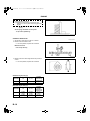
CONTENTS
Title
Section
General Information
GI
Engine
B
Technical Data
TD
Special Tools
ST
© 2002 Mazda Motor Corporation
PRINTED IN The Netherlands, MARCH 2002
1731–1E–02C
1731-1E-02C(WARNING).fm
1 ページ
2002年3月13日 水曜日 午後5時9分
WARNING
Servicing a vehicle can be dangerous. If you have not received
service-related training, the risks of injury, property damage, and
failure of servicing increase. The recommended servicing procedures
for the vehicle in this workshop manual were developed with
Mazda-trained technicians in mind. This manual may be useful to
non-Mazda trained technicians, but a technician with our
service-related training and experience will be at less risk when
performing service operations. However, all users of this manual are
expected to at least know general safety procedures.
This manual contains "Warnings" and "Cautions" applicable to risks
not normally encountered in a general technician's experience.
They should be followed to reduce the risk of injury and the risk that
improper service or repair may damage the vehicle or render it unsafe.
It is also important to understand that the "Warnings" and "Cautions"
are not exhaustive. It is impossible to warn of all the hazardous
consequences that might result from failure to follow the procedures.
The procedures recommended and described in this manual are
effective methods of performing service and repair. Some require tools
specifically designed for a specific purpose. Persons using procedures
and tools which are not recommended by Mazda Motor Corporation
must satisfy themselves thoroughly that neither personal safety nor
safety of the vehicle will be jeopardized.
The contents of this manual, including drawings and specifications, are
the latest available at the time of printing, and Mazda Motor Corporation
reserves the right to change the vehicle designs and alter the contents
of this manual without notice and without incurring obligation.
Parts should be replaced with genuine Mazda replacement parts or
with parts which match the quality of genuine Mazda replacement
parts. Persons using replacement parts of lesser quality than that of
genuine Mazda replacement parts must satisfy themselves thoroughly
that neither personal safety nor safety of the vehicle will be
jeopardized.
Mazda Motor Corporation is not responsible for any problems which
may arise from the use of this manual. The cause of such problems
includes but is not limited to insufficient service-related training, use of
improper tools, use of replacement parts of lesser quality than that of
genuine Mazda replacement parts, or not being aware of any revision
of this manual.
1731-1E-02C.book
1 ページ
2002年4月26日 金曜日 午前10時30分
GENERAL INFORMATION
GI
GI
HOW TO USE THIS MANUAL ............................. GI-2
RANGE OF TOPICS .......................................... GI-2
SERVICE PROCEDURE ................................... GI-2
SYMBOLS.......................................................... GI-3
ADVISORY MESSAGES ................................... GI-4
UNITS ................................................................... GI-5
UNITS ................................................................ GI-5
FUNDAMENTAL PROCEDURES ........................ GI-6
PREPARATION OF TOOLS AND
MEASURING EQUIPMENT ............................ GI-6
SPECIAL SERVICE TOOLS .............................. GI-6
DISASSEMBLY.................................................. GI-6
INSPECTION DURING REMOVAL,
DISASSEMBLY............................................... GI-7
ARRANGEMENT OF PARTS ............................ GI-7
CLEANING OF PARTS...................................... GI-7
REASSEMBLY................................................... GI-7
ADJUSTMENT ................................................... GI-8
RUBBER PARTS AND TUBING ........................ GI-8
HOSE CLAMPS ................................................. GI-8
TORQUE FORMULAS....................................... GI-9
VISE ................................................................... GI-9
SST .................................................................... GI-9
ELECTRICAL SYSTEM...................................... GI-10
ELECTRICAL PARTS ...................................... GI-10
CONNECTORS................................................ GI-10
NEW STANDARDS ............................................ GI-13
NEW STANDARDS.......................................... GI-13
ABBREVIATIONS .............................................. GI-15
ABBREVIATIONS ............................................ GI-15
GI–1
1731-1E-02C.book
2 ページ
2002年4月26日 金曜日 午前10時30分
HOW TO USE THIS MANUAL
HOW TO USE THIS MANUAL
RANGE OF TOPICS
A6E201000001E01
• This manual contains procedures for performing all required service operations. The procedures are divided
into the following five basic operations:
— Removal/Installation
— Disassembly/Assembly
— Replacement
— Inspection
— Adjustment
• Simple operations which can be performed easily just by looking at the vehicle (i.e., removal/installation of
parts, jacking, vehicle lifting, cleaning of parts and visual inspection) have been omitted.
End Of Sie
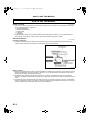
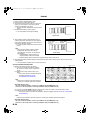
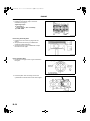
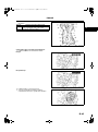
SERVICE PROCEDURE
A6E201000001E02
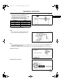
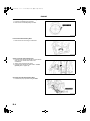
Inspection, adjustment
• Inspection and adjustment procedures are divided into steps. Important points regarding the location and
contents of the procedures are explained in detail and shown in the illustrations.
XME2010001
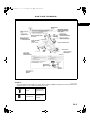
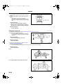
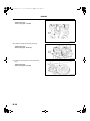
Repair procedure
1. Most repair operations begin with an overview illustration. It identifies the components, shows how the parts fit
together and describes visual part inspection. However, only removal/installation procedures that need to be
performed methodically have written instructions.
2. Expendable parts, tightening torques and symbols for oil, grease, and sealant are shown in the overview
illustration. In addition, symbols indicating parts requiring the use of special service tools or equivalent are also
shown.
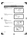
3. Procedure steps are numbered and the part that is the main point of that procedure is shown in the illustration
with the corresponding number. Occasionally, there are important points or additional information concerning a
procedure. Refer to this information when servicing the related part.
GI–2
1731-1E-02C.book
3 ページ
2002年4月26日 金曜日 午前10時30分
HOW TO USE THIS MANUAL
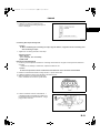
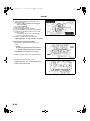
4.
GI
XME2010010
End Of Sie
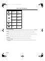
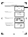
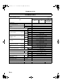
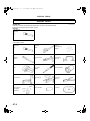
SYMBOLS
A6E201000001E03
• There are eight symbols indicating oil, grease, fluids, sealant, and SST or equivalent use. These symbols show
application points or use of these materials during service.
Symbol
Meaning
Kind
Apply oil
New appropriate
engine oil or gear
oil
Apply brake fluid
New appropriate
brake fluid
GI–3
1731-1E-02C.book
4 ページ
2002年4月26日 金曜日 午前10時30分
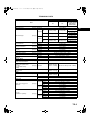
HOW TO USE THIS MANUAL
Symbol
Meaning
Kind
Apply automatic
transaxle/
transmission fluid
New appropriate
automatic
transaxle/
transmission fluid
Apply grease
Appropriate
grease
Apply sealant
Appropriate
sealant
Apply petroleum
jelly
Appropriate
petroleum jelly
Replace part
O-ring, gasket,
etc.
Use SST or
equivalent
Appropriate tools
End Of Sie
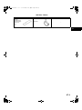
ADVISORY MESSAGES
A6E201000001E04
• You'll find several Warnings, Cautions, Notes, Specifications and Upper and Lower Limits in this manual.
Warning
• A Warning indicates a situation in which serious injury or death could result if the warning is ignored.
Caution
• A Caution indicates a situation in which damage to the vehicle or parts could result if the caution is ignored.
Note
• A Note provides added information that will help you to complete a particular procedure.
Specification
• The values indicate the allowable range when performing inspections or adjustments.
Upper and lower limits
• The values indicate the upper and lower limits that must not be exceeded when performing inspections or
adjustments.
End Of Sie
GI–4
1731-1E-02C.book
5 ページ
2002年4月26日 金曜日 午前10時30分
UNITS
UNITS
GI
UNITS
Electrical current
Electric power
Electric resistance
Electric voltage
Length
Negative pressure
Positive pressure
Torque
Volume
Weight
A6E201200002E01
A (ampere)
W (watt)
ohm
V (volt)
mm (millimeter)
in (inch)
kPa (kilo pascal)
mmHg (millimeters of mercury)
inHg (inches of mercury)
kPa (kilo pascal)
kgf/cm2 (kilogram force per square
centimeter)
psi (pounds per square inch)
N·m (Newton meter)
kgf·m (kilogram force meter)
kgf·cm (kilogram force centimeter)
ft·lbf (foot pound force)
in·lbf (inch pound force)
L (liter)
US qt (U.S. quart)
Imp qt (Imperial quart)
ml (milliliter)
cc (cubic centimeter)
cu in (cubic inch)
fl oz (fluid ounce)
g (gram)
oz (ounce)
Conversion to SI Units (Système International d'Unités)
• All numerical values in this manual are based on SI units. Numbers shown in conventional units are converted
from these values.
Rounding Off
• Converted values are rounded off to the same number of places as the SI unit value. For example, if the SI unit
value is 17.2 and the value after conversion is 37.84, the converted value will be rounded off to 37.8.
Upper and Lower Limits
• When the data indicates upper and lower limits, the converted values are rounded down if the SI unit value is
an upper limit and rounded up if the SI unit value is a lower limit. Therefore, converted values for the same SI
unit value may differ after conversion. For example, consider 2.7 kgf/cm2 in the following specifications:
210—260 kPa {2.1—2.7 kgf/cm2, 30—38 psi}
270—310 kPa {2.7—3.2 kgf/cm2, 39—45 psi}
• The actual converted values for 2.7 kgf/cm2 are 264 kPa and 38.4 psi. In the first specification, 2.7 is used as
an upper limit, so the converted values are rounded down to 260 and 38. In the second specification, 2.7 is
used as a lower limit, so the converted values are rounded up to 270 and 39.
End Of Sie
GI–5
1731-1E-02C.book
6 ページ
2002年4月26日 金曜日 午前10時30分
FUNDAMENTAL PROCEDURES
FUNDAMENTAL PROCEDURES
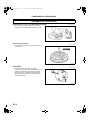
PREPARATION OF TOOLS AND MEASURING EQUIPMENT
• Be sure that all necessary tools and measuring
equipment are available before starting any work.
A6E201400004E02
X3U000WAH
End Of Sie
SPECIAL SERVICE TOOLS
• Use special service tools or equivalent when they
are required.
A6E201400004E03
X3U000WAJ
End Of Sie
DISASSEMBLY
• If the disassembly procedure is complex,
requiring many parts to be disassembled, all parts
should be marked in a place that will not affect
their performance or external appearance and
identified so that reassembly can be performed
easily and efficiently.
A6E201400004E07
X3U000WAL
End Of Sie
GI–6
1731-1E-02C.book
7 ページ
2002年4月26日 金曜日 午前10時30分
FUNDAMENTAL PROCEDURES
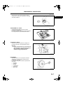
INSPECTION DURING REMOVAL, DISASSEMBLY
• When removed, each part should be carefully
inspected for malfunction, deformation, damage,
and other problems.
A6E201400004E08
GI
X3U000WAM
End Of Sie
ARRANGEMENT OF PARTS
• All disassembled parts should be carefully
arranged for reassembly.
• Be sure to separate or otherwise identify the parts
to be replaced from those that will be reused.
A6E201400004E09
X3U000WAN
End Of Sie
CLEANING OF PARTS
• All parts to be reused should be carefully and
thoroughly cleaned in the appropriate method.
A6E201400004E10
Warning
• Using compressed air can cause dirt and
other particles to fly out causing injury to
the eyes. Wear protective eye wear
whenever using compressed air.
WGIWXX0030J
End Of Sie
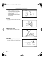
REASSEMBLY
• Standard values, such as torques and certain
adjustments, must be strictly observed in the
reassembly of all parts.
• If removed, these parts should be replaced with
new ones:
— Oil seals
— Gaskets
— O-rings
— Lockwashers
— Cotter pins
— Nylon nuts
A6E201400004E11
WGIWXX0031J
GI–7
1731-1E-02C.book
8 ページ
2002年4月26日 金曜日 午前10時30分
FUNDAMENTAL PROCEDURES
• Depending on location:
— Sealant and gaskets, or both, should be
applied to specified locations. When sealant
is applied, parts should be installed before
sealant hardens to prevent leakage.
— Oil should be applied to the moving
components of parts.
— Specified oil or grease should be applied at
the prescribed locations (such as oil seals)
before reassembly.
WGIWXX0032J
End Of Sie
ADJUSTMENT
• Use suitable gauges and/or testers when making
adjustments.
A6E201400004E12
X3U000WAS
End Of Sie
RUBBER PARTS AND TUBING
• Prevent gasoline or oil from getting on rubber
parts or tubing.
A6E201400004E13
WGIWXX0034E
End Of Sie
HOSE CLAMPS
• When reinstalling, position the hose clamp in the
original location on the hose and squeeze the
clamp lightly with large pliers to ensure a good fit.
A6E201400004E14
WGIWXX0035J
End Of Sie
GI–8
1731-1E-02C.book
9 ページ
2002年4月26日 金曜日 午前10時30分
FUNDAMENTAL PROCEDURES
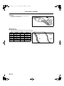
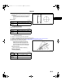
TORQUE FORMULAS
• When using a torque wrench-SST or equivalent
combination, the written torque must be
recalculated due to the extra length that the SST
or equivalent adds to the torque wrench.
Recalculate the torque using the following
formulas. Choose the formula that applies to you.
Torque Unit
N·m
kgf·m
kgf·cm
ft·lbf
in·lbf
Formula
N·m × [L/(L+A)]
kgf·m × [L/(L+A)]
kgf·cm × [L/(L+A)]
ft·lbf × [L/(L+A)]
in·lbf × [L/(L+A)]
A6E201400004E15
GI
WGIWXX0036E
A : The length of the SST past the torque wrench drive
L : The length of the torque wrench
End Of Sie
VISE
• When using a vise, put protective plates in the
jaws of the vise to prevent damage to parts.
A6E201400004E16
X3U000WAW
End Of Sie
SST
A6E201400004E18
• Some Ford SST or equivalent are used as SSTs necessary for engine repair. Note that these SSTs are
marked with Ford SST numbers.
• Note that a Ford SST number is written together with a corresponding Mazda SST number as shown below.
Example (section ST)
XME2014002
Example (except section ST)End Of Sie
XME2014001
GI–9
1731-1E-02C.book
10 ページ
2002年4月26日 金曜日 午前10時30分
ELECTRICAL SYSTEM
ELECTRICAL SYSTEM
ELECTRICAL PARTS
A6E201700006E01
Battery cable
• Before disconnecting connectors or removing
electrical parts, disconnect the negative battery
cable.
WGIWXX0007E
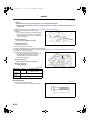
Wiring Harness
• To remove the wiring harness from the clip in the
engine room, pry up the hook of the clip using a
flathead screwdriver.
X3U000WBU
End Of Sie
CONNECTORS
A6E201700006E02
Data link connector
• Insert the probe into the terminal when
connecting a jumper wire to the data link
connector.
Caution
• Inserting a jumper wire probe into the
data link connector terminal may damage
the terminal.
X3U000WAY
Disconnecting connectors
• When disconnecting connector, grasp the
connectors, not the wires.
WGIWXX0041E
GI–10
1731-1E-02C.book
11 ページ
2002年4月26日 金曜日 午前10時30分
ELECTRICAL SYSTEM
• Connectors can be disconnected by pressing or
pulling the lock lever as shown.
GI
WGIWXX0042E
Locking connector
• When locking connectors, listen for a click
indicating they are securely locked.
X3U000WB1
Inspection
• When a tester is used to inspect for continuity or
measuring voltage, insert the tester probe from
the wiring harness side.
X3U000WB2
• Inspect the terminals of waterproof connectors
from the connector side since they cannot be
accessed from the wiring harness side.
Caution
• To prevent damage to the terminal, wrap
a thin wire around the tester probe before
inserting into terminal.
WGIWXX0045E
GI–11
1731-1E-02C.book
12 ページ
2002年4月26日 金曜日 午前10時30分
ELECTRICAL SYSTEM
Terminals
Inspection
• Pull lightly on individual wires to verify that they
are secured in the terminal.
X3U000WB4
Wiring Harness
Wiring color codes
• Two-color wires are indicated by a two-color code symbol.
• The first letter indicates the base color of the wire and the second the color of the stripe.
CODE
B
BR
G
GY
L
LB
LG
COLOR
Black
Brown
Green
Gray
Blue
Light Blue
Light Green
CODE
O
P
R
V
W
Y
COLOR
Orange
Pink
Red
Violet
White
Yellow
End Of Sie
X3U000WB7
GI–12
1731-1E-02C.book
13 ページ
2002年4月26日 金曜日 午前10時30分
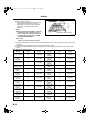
NEW STANDARDS
NEW STANDARDS
GI
NEW STANDARDS
A6E202800020E01
• Following is a comparison of the previous standard and the new standard.
New Standard
Abbreviation
AP
ACL
A/C
BARO
B+
—
—
CMP sensor
CAC
CLS
CTP
CPP
CIS
CS sensor
CKP sensor
DLC
DTM
DTC
DI
DLI
EI
ECT
EM
—
EVAP
EGR
FC
FF
4GR
—
FSO
solenoid
GEN
GND
HO2S
IAC
—
—
—
—
IAT
KS
MIL
MAP
MAF sensor
MFL
OBD
OL
Name
Accelerator Pedal
Air Cleaner
Air Conditioning
Barometric Pressure
Battery Positive Voltage
Brake Switch
Calibration Resistor
Camshaft Position Sensor
Charge Air Cooler
Closed Loop System
Closed Throttle Position
Clutch Pedal Position
Continuous Fuel Injection System
Control Sleeve Sensor
Crankshaft Position Sensor
Data Link Connector
Diagnostic Test Mode
Diagnostic Trouble Code(s)
Distributor Ignition
Distributorless Ignition
Electronic Ignition
Engine Coolant Temperature
Engine Modification
Engine Speed Input Signal
Evaporative Emission
Exhaust Gas Recirculation
Fan Control
Flexible Fuel
Fourth Gear
Fuel Pump Relay
Previous Standard
Abbreviation
—
—
—
—
Vb
—
—
—
—
—
—
—
—
CSP sensor
—
—
—
—
—
—
—
—
—
—
—
—
—
—
—
—
Name
Accelerator Pedal
Air Cleaner
Air Conditioning
Atmospheric Pressure
Battery Voltage
Stoplight Switch
Corrected Resistance
Crank Angle Sensor
Intercooler
Feedback System
Fully Closed
Idle Switch
Clutch Position
Control Sleeve Position Sensor
Crank Angle Sensor 2
Diagnosis Connector
Test Mode
Service Code(s)
Spark Ignition
Direct Ignition
Electronic Spark Ignition
Water Thermo
Engine Modification
Engine RPM Signal
Evaporative Emission
Exhaust Gas Recirculation
Fan Control
Flexible Fuel
Overdrive
Circuit Opening Relay
Remark
#6
#6
#1
#2
#3
Fuel Shut Off Solenoid
FCV
Fuel Cut Valve
#6
Generator
Ground
Heated Oxygen Sensor
Idle Air control
IDM Relay
Incorrect Gear Ratio
Injection Pump
Input/Turbine Speed Sensor
Intake Air Temperature
Knock Sensor
Malfunction Indicator Lamp
Manifold Absolute Pressure
Mass Air Flow Sensor
Multiport Fuel Injection
On-Board Diagnostic
Open Loop
—
—
—
—
—
—
FIP
—
—
—
—
—
—
—
—
—
Alternator
Ground/Earth
Oxygen Sensor
Idle Speed Control
Spill Valve Relay
With heater
—
Fuel Injection Pump
Pulse Generator
Intake Air Thermo
Knock Sensor
Malfunction Indicator Light
Intake Air Pressure
Airflow Sensor
Multiport Fuel Injection
Diagnosis/SelfDiagnosis
Open Loop
#6
#6
GI–13
1731-1E-02C.book
14 ページ
2002年4月26日 金曜日 午前10時30分
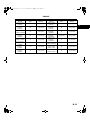
NEW STANDARDS
New Standard
Abbreviation
—
OC
O2S
PNP
—
PSP
PCM
—
PAIR
—
AIR
SAPV
SFI
Name
Output Speed Sensor
Oxidation Catalytic Converter
Oxygen Sensor
Park/Neutral Position
PCM Control Relay
Power Steering Pressure
Powertrain Control Module
Pressure Control Solenoid
Name
Vehicle Speed Sensor 1
Catalytic Converter
Oxygen Sensor
Park/Neutral Range
Main Relay
Power Steering Pressure
Engine Control Unit
Line Pressure Solenoid Valve
Pulsed Secondary Air Injection
—
Secondary Air Injection System
Pump Speed Sensor
—
NE Sensor
Secondary Air Injection
—
Secondary Air Injection System
Secondary Air Pulse Valve
Sequential Multipoint Fuel Injection
—
Shift Solenoid A
—
Shift Solenoid B
—
3GR
TWC
TB
TP sensor
TCV
TCC
Previous Standard
Abbreviation
—
—
—
—
—
—
ECU
—
Shift Solenoid C
Third Gear
Three Way Catalytic Converter
Throttle Body
Throttle Position Sensor
Timer Control Valve
Torque Converter Clutch
Transmission (Transaxle) Control
TCM
Module
Transmission (Transaxle) Fluid
—
Temperature Sensor
TR
Transmission (Transaxle) Range
TC
Turbocharger
VSS
Vehicle Speed Sensor
VR
Voltage Regulator
VAF sensor Volume Air Flow Sensor
Warm Up Three Way Catalytic
WUTWC
Converter
WOT
Wide Open Throttle
—
—
—
—
—
—
—
—
—
—
—
TCV
—
Reed Valve
Sequential Fuel Injection
1–2 Shift Solenoid Valve
Shift A Solenoid Valve
2–3 Shift Solenoid Valve
Shift B Solenoid Valve
3–4 Shift Solenoid Valve
3rd Gear
Catalytic Converter
Throttle Body
Throttle Sensor
Timing Control Valve
Lockup Position
—
ECAT Control Unit
—
ATF Thermosensor
—
—
—
—
—
Inhibitor Position
Turbocharger
Vehicle Speed Sensor
IC Regulator
Air flow Sensor
—
Catalytic Converter
—
Fully Open
Remark
#6
#4
Pulsed
injection
#6
Injection
with air
pump
#6
#5
#1 : Diagnostic trouble codes depend on the diagnostic test mode
#2 : Controlled by the PCM
#3 : In some models, there is a fuel pump relay that controls pump speed. That relay is now called the fuel pump
relay (speed).
#4 : Device that controls engine and powertrain
#5 : Directly connected to exhaust manifold
#6 : Part name of diesel engine
End Of Sie
GI–14
1731-1E-02C.book
15 ページ
2002年4月26日 金曜日 午前10時30分
ABBREVIATIONS
ABBREVIATIONS
ABBREVIATIONS
MTX
ATX
ATDC
TDC
IN
EX
EGR
OCV
SST
GI
A6E203000011E01
Manual transaxle
Automatic transaxle
After top dead center
Top dead center
Intake
Exhaust
Exhaust gas recirculation
Oil control valve
Special service tool
End Of Sie
GI–15
1731-1E-02C.book
1 ページ
2002年4月26日 金曜日 午前10時30分
ENGINE
B
B
ENGINE .................................................................. B-2
ENGINE OVERHAUL SERVICE WARNING ....... B-2
ENGINE MOUNTING/DISMOUNTING ................ B-2
TIMING CHAIN DISASSEMBLY .......................... B-3
CYLINDER HEAD (I) DISASSEMBLY ................. B-5
CYLINDER HEAD (II) DISASSEMBLY ................ B-7
CYLINDER BLOCK (I) DISASSEMBLY ............... B-9
CYLINDER BLOCK (II) DISASSEMBLY ............ B-10
CYLINDER HEAD INSPECTION ....................... B-11
VALVE, VALVE GUIDE INSPECTION............... B-12
VALVE GUIDE REPLACEMENT ....................... B-13
VALVE SEAT INSPECTION/REPAIR................ B-15
VALVE SPRING INSPECTION.......................... B-15
CAMSHAFT INSPECTION ................................ B-16
TAPPET INSPECTION ...................................... B-17
CYLINDER BLOCK INSPECTION..................... B-18
OIL JET VALVE INSPECTION .......................... B-19
PISTON INSPECTION....................................... B-19
CRANKSHAFT INSPECTION............................ B-20
CONNECTING ROD INSPECTION ................... B-22
BOLT INSPECTION........................................... B-22
VARIABLE VALVE TIMING ACTUATOR
INSPECTION .................................................. B-23
OIL CONTROL VALVE (OCV) INSPECTION .... B-23
VALVE CLEARANCE INSPECTION.................. B-24
VALVE CLEARANCE ADJUSTMENT ............... B-25
CYLINDER BLOCK (I) ASSEMBLY ................... B-29
CYLINDER BLOCK (II) ASSEMBLY .................. B-34
CYLINDER HEAD (I) ASSEMBLY ..................... B-37
CYLINDER HEAD (II) ASSEMBLY .................... B-39
TIMING CHAIN ASSEMBLY .............................. B-41
B–1
1731-1E-02C.book
2 ページ
2002年4月26日 金曜日 午前10時30分
ENGINE
ENGINE
ENGINE OVERHAUL SERVICE WARNING
A6E242402000E01
Warning
• Continuous exposure with USED engine oil has caused skin cancer in laboratory mice. Protect
your skin by washing with soap and water immediately after this work.
End Of Sie
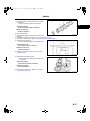
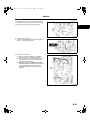
ENGINE MOUNTING/DISMOUNTING
A6E242402000E02
1. Install the SSTs (arms) to the cylinder block holes
as shown, and hand-tighten the bolts (part No.:
×1.5T length 90 mm {3.55
9YA20-1003) or M10×
in}.
AME2224E065
2. Assemble the SSTs (bolts, nuts and plate) to the
specified positions.
3. Adjust the SSTs (bolts) so that less than 20 mm
{0.79 in} of thread is exposed.
4. Make the SSTs (arms and plate) parallel by
adjusting the SSTs (bolts and nuts).
AME2224E300
5. Tighten the SSTs (bolts and nuts) to affix the
SSTs firmly.
Warning
• Self-locking brake system of the engine
stand may not be effective when the
engine is held in an unbalanced position.
This could lead to sudden, rapid
movement of the engine and mounting
stand handle and cause serious injury.
Never keep the engine in an unbalanced
position, and always hold the rotating
handle firmly when turning the engine.
6. Mount the engine on the SST (engine stand).
7. Drain the engine oil into a container.
8. Clean the flange surface (seal rubber) of the oil pan drain plug, then install the oil pan drain plug.
Tightening torque
20—30 N·m {2.1—3.0 kgf·m, 15—22 ft·lbf}
DISMOUNTING
• Dismount in the reverse order of mounting.
End Of Sie
B–2
AME2224E301
1731-1E-02C.book
3 ページ
2002年4月26日 金曜日 午前10時30分
ENGINE
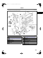
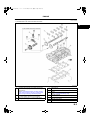
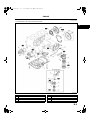
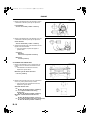
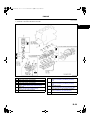
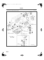
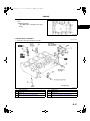
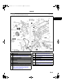
TIMING CHAIN DISASSEMBLY
A6E242402000E04
1. Disassemble in the order indicated in the table.
.
B
AME2224E337
1
2
3
4
5
6
7
8
Spark plug
Cylinder head cover
Crankshaft pulley lock bolt
(See B–4 Crankshaft Pulley Lock Bolt Disassembly
Note)
Crankshaft pulley
Water pump pulley
Drive belt idler pulley
Engine front cover
Front oil seal
(See B–4 Front Oil Seal Disassembly Note)
9
10
11
12
13
14
15
16
17
18
Chain tensioner
(See B–4 Chain Tensioner Disassembly Note)
Tensioner arm
Chain guide
Timing chain
Seal (L3 (with variable valve timing mechanism))
Oil pump chain tensioner
Oil pump chain guide
Oil pump sprocket
(See B–4 Oil Pump Sprocket Disassembly Note)
Oil pump chain
Crankshaft sprocket
B–3
1731-1E-02C.book
4 ページ
2002年4月26日 金曜日 午前10時30分
ENGINE
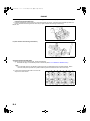
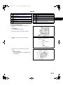
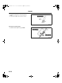
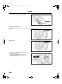
Crankshaft Pulley Lock Bolt Disassembly Note
1. Hold the crankshaft using the SST.
2. Remove the crankshaft pulley lock bolt.
AME2224E106
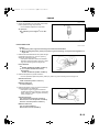
Front Oil Seal Disassembly Note
1. Remove the oil seal using a screwdriver.
AME2224E338
Chain Tensioner Disassembly Note
1. Hold the chain tensioner ratchet lock mechanism
away from the ratchet stem with a thin
screwdriver.
2. Slowly press the tensioner piston.
3. Hold the chain tensioner piston with a 1.5 mm
{0.06 in} wire or paper clip.
AME2224E339
Oil Pump Sprocket Disassembly Note
1. Hold the oil pump sprocket using the SST.
AME2224E340
End Of Sie
B–4
1731-1E-02C.book
5 ページ
2002年4月26日 金曜日 午前10時30分
ENGINE
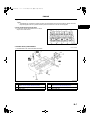
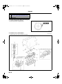
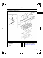
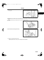
CYLINDER HEAD (I) DISASSEMBLY
A6E242402000E05
1. Disassemble in the order indicated in the table.
2.
B
AME2224E001
.
1
2
3
Camshaft sprocket lock bolt,Variable valve timing
actuator lock bolt (L3 (with variable valve timing
mechanism))
(See B–6 Camshaft Sprocket Lock Bolt, Variable
Valve Timing Actuator Lock Bolt (L3 (with variable
valve timing mechanism)) Disassembly Note)
Camshaft sprocket,Variable valve timing actuator
(L3 (with variable valve timing mechanism))
Oil control valve (OCV) (L3 (with variable valve
timing mechanism))
4
5
6
7
8
9
10
Camshaft cap
(See B–6 Camshaft Cap Disassembly Note)
Camshaft
Tappet
(See B–7 Tappet Disassembly Note)
Cylinder head bolt
(See B–7 Cylinder Head Bolt Disassembly Note)
Cylinder head
Cylinder head gasket
Cylinder block
B–5
1731-1E-02C.book
6 ページ
2002年4月26日 金曜日 午前10時30分
ENGINE
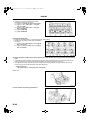
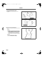
Camshaft Sprocket Lock Bolt, Variable Valve Timing Actuator Lock Bolt (L3 (with variable valve timing
mechanism)) Disassembly Note
1. Hold the camshaft by using a wrench on the cast hexagon as shown, and loosen the camshaft sprocket lock
bolt or variable valve timing actuator lock bolt (L3 (with variable valve timing mechanism)).
L8, LF, L3
AME2224E077
L3 (with variable valve timing mechanism)
AME2224E078
Camshaft Cap Disassembly Note
1. Before removing the camshaft caps, inspect the following.
— Camshaft end play and camshaft journal oil clearance (See B–16 CAMSHAFT INSPECTION.)
Note
• The camshaft caps are numbered to make sure they are assembled in their original positions. When
removed, keep the caps with the cylinder head they were removed from. Do not mix the caps.
2. Loosen the camshaft caps bolts in two or three
steps in the order shown.
AME2224E006
B–6
1731-1E-02C.book
7 ページ
2002年4月26日 金曜日 午前10時30分
ENGINE
Tappet Disassembly Note
Note
• The tappets are numbered to make sure they are assembled in their original positions. When removed,
keep the tappets with the cylinder head they were removed from. Do not mix the tappets.
B
Cylinder Head Bolt Disassembly Note
1. Loosen the cylinder head bolts in two or three
steps in the order shown.
AME2224E005
End Of Sie
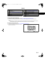
CYLINDER HEAD (II) DISASSEMBLY
A6E242402000E06
1. Disassemble in the order indicated in the table.
2.
AME2224E008
.
1
2
3
4
Engine hanger
Valve keeper
(See B–8 Valve Keeper Disassembly Note)
Upper valve spring seat
Valve spring
5
6
7
8
Valve
Valve seal
(See B–8 Valve Seal Disassembly Note)
EGR pipe
Water outlet case
B–7
1731-1E-02C.book
8 ページ
2002年4月26日 金曜日 午前10時30分
ENGINE
Valve Keeper Disassembly Note
1. Remove the valve keeper using the SSTs.
AME2224E302
Valve Seal Disassembly Note
1. Remove the valve seal using the SST.
AME2224E303
End Of Sie
B–8
1731-1E-02C.book
9 ページ
2002年4月26日 金曜日 午前10時30分
ENGINE
CYLINDER BLOCK (I) DISASSEMBLY
A6E242402000E07
1. Disassemble in the order indicated in the table.
2.
B
AME2224E011
.
1
2
3
4
5
Oil pan
Oil filter cover
Oil filter
Oil filter adapter
Oil cooler
6
7
8
9
10
Knock sensor
Oil separator
Thermostat
Water pump
Oil strainer
B–9
1731-1E-02C.book
10 ページ
2002年4月26日 金曜日 午前10時30分
ENGINE
11
12
13
14
Oil pump
Flywheel (MTX ), Drive plate (ATX) (See B–10 Drive
Plate (ATX), Flywheel (MTX) Disassembly Note)
End plate (MTX)
Rear oil seal
Drive Plate (ATX), Flywheel (MTX) Disassembly Note
1. Hold the crankshaft using the SST.
2. Remove the bolts in several passes.
AME2224E106
End Of Sie
CYLINDER BLOCK (II) DISASSEMBLY
A6E242402000E08
1. Disassemble in the order indicated in the table.
2.
AME2224E012
B–10
1731-1E-02C.book
11 ページ
2002年4月26日 金曜日 午前10時30分
ENGINE
.
1
2
3
4
5
6
Balancer unit (L3, L3 (with variable valve timing
mechanism))
Connecting rod cap
(See B–11 Connecting Rod Cap Disassembly Note)
Lower connecting rod bearing
Upper connecting rod bearing
Connecting rod, Piston assembly
Piston ring
7
8
9
10
11
12
13
Main bearing cap
(See B–11 Main Bearing Cap Disassembly Note)
Lower main bearing, thrust bearing
Crankshaft
Upper main bearing, thrust bearing
Oil jet valve
Cylinder block
Adjustment shim
Connecting Rod Cap Disassembly Note
1. Inspect the connecting rod side clearance. (See B–22 CONNECTING ROD INSPECTION .)
2. Remove the connecting rod bolt from the connecting rod cap by tapping the bolt with a plastic hammer.
Note
• The tappets are numbered to make sure they are assembled in their original positions. When removed,
keep the tappets with the cylinder head they were removed from. Do not mix the tappets.
Main Bearing Cap Disassembly Note
1. Inspect the crankshaft end play. (See B–20 CRANKSHAFT INSPECTION .)
2. Loosen the main bearing cap bolts in two or three
steps in the order shown.
AME2224E341
End Of Sie
B–11
B
1731-1E-02C.book
12 ページ
2002年4月26日 金曜日 午前10時30分
ENGINE
CYLINDER HEAD INSPECTION
A6E242410100E01
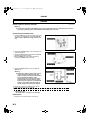
1. Carry out color contrast penetrate examination on the cylinder head surface.
• Replace the cylinder head if necessary.
2. Inspect for the following and repair or replace if necessary.
(1) Sunken valve seats
(2) Excessive camshaft oil clearance and end play
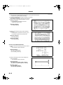
3. Measure the cylinder head for distortion in the six
directions as shown.
• If the distortion exceeds the maximum,
replace the cylinder head.
Maximum distortion:
0.10 mm {0.004 in}
AME2224E317
4. Measure the manifold contact surface distortion
as shown.
• If the distortion exceeds the maximum, grind
the surface or replace the cylinder head.
Maximum distortion:
0.10 mm {0.004 in}
Maximum grinding:
0.15 mm {0.006 in}
AME2224E318
End Of Sie
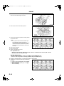
VALVE, VALVE GUIDE INSPECTION
A6E242412111E01
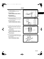
1. Measure the valve head margin thickness of each
valve.
• If not specified, replace the valve.
Margin thickness:
IN: 1.62 mm {0.0637 in}
EX: 1.82 mm {0.0716 in}
AME2224E070
2. Measure the length of each valve. Replace the
valve if necessary.
• If not specified, replace the valve.
Standard length L:
IN: 102.99—103.79 mm {4.055—4.086 in}
EX: 104.25—105.05 mm {4.105—4.135 in}
Minimum length L:
IN: 102.99 mm {4.055 in}
EX: 103.79 mm {4.086 in}
AME2224E071
B–12
1731-1E-02C.book
13 ページ
2002年4月26日 金曜日 午前10時30分
ENGINE
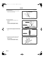
3. Measure the stem diameter of each valve in X
and Y directions at the three points (A, B, and C)
as indicated in the figure.
• If not as specified, replace the valve.
B
Standard diameter:
IN: 5.470—5.485 mm {0.2154—0.2159 in}
EX: 5.465—5.480 mm {0.2152—0.2157 in}
Maximum diameter:
IN: 5.440 mm {0.2142 in}
EX: 5.435 mm {0.2140 in}
AME2224E313
4. Measure the inner diameter of each valve guide
in X and Y directions at the three points (A, B, and
C) as indicated in the figure.
• If not as specified, replace the valve guide.
Standard Inner diameter:
IN: 5.509—5.539 mm {0.2169—0.2180 in}
EX: 5.509—5.539 mm {0.2169—0.2180 in}
AME2224E314
5. Calculate the valve stem to guide clearance by
subtracting the outer diameter of the valve stem
from the inner diameter of the corresponding
valve guide.
• If not as specified, replace the valve and/or
the valve guide.
Standard clearance:
IN: 0.024—0.069 mm {0.0009—0.0027 in}
EX: 0.029—0.074 mm {0.0012—0.0029 in}
Maximum clearance:
0.10 mm {0.004 in}
AME2224E315
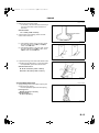
6. Measure the protrusion height (dimension A) of
each valve guide without lower valve spring seat.
• If not as specified, replace the valve guide.
Standard diameter:
IN: 12.2—12.8 mm {0.481—0.503 in}
EX: 12.2—12.8 mm {0.481—0.503 in}
AME2224E073
End Of Sie
B–13
1731-1E-02C.book
14 ページ
2002年4月26日 金曜日 午前10時30分
ENGINE
VALVE GUIDE REPLACEMENT
A6E242412111E04
Valve Guide Removal
1. Remove the valve guide from the combustion
chamber side using the SST.
AME2224E312
Valve Guide Installation
1. Assemble the SSTs so that depth L is as
specified.
Depth L:
IN: 12.2—12.8 mm {0.481—0.501 in}
EX: 12.2—12.8 mm {0.481—0.501 in}
AME2224E107
2. Tap the valve guide in from the side opposite the
camshaft side until the SSTs contacts the cylinder
head.
AME2224E018
3. Verify that the valve guide projection height
(dimension A ) is within the specification.
Standard height:
IN: 12.2—12.8 mm {0.481—0.501 in}
EX: 12.2—12.8 mm {0.481—0.501 in}
AME2224E073
End Of Sie
B–14
1731-1E-02C.book
15 ページ
2002年4月26日 金曜日 午前10時30分
ENGINE
VALVE SEAT INSPECTION/REPAIR
A6E242410102E01
1. Measure the seat contact width.
• If necessary, resurface the valve seat using a
45° valve seat cutter and/or resurface the
valve face.
B
Standard width:
1.2—1.6 mm {0.048—0.062 in}
2. Verify that the valve seating position is at the
center of the valve face.
AME2224E316
(1) If the seating position is too out side, correct
the valve seat using a 70°° (IN) or 65°° (EX)
cutter, and a 45°° cutter.
(2) If the seating position is too inner side, correct
the valve seat using a 30°° (IN) cutter, and a
0°° (EX) cutter, and a 45°° cutter.
AME2224E020
3. Inspect the sinking of the valve seat. Measure the
protruding length (dimension L) of the valve stem.
• If not specified, replace the cylinder head.
Standard dimension L:
IN: 40.64—42.24 mm {1.600—1.662 in}
EX: 40.50—42.10 mm {1.595—1.657 in}
AME2224E079
End Of Sie
VALVE SPRING INSPECTION
A6E242412125E01
1. Apply pressing force to the pressure spring and
inspect the spring height.
• If not as specified, replace the valve spring.
Pressing force:
494.9 N {50.47 kgf, 111.2 lbf}
Standard height:
27.80 mm {1.094 in}
AME2224E308
B–15
1731-1E-02C.book
16 ページ
2002年4月26日 金曜日 午前10時30分
ENGINE
2. Measure the out-of-square of the valve spring,
using a square, as shown.
(1) Rotate the valve spring one full turn and
measure "A" at the point where the gap is the
largest.
• If not as specified, replace the valve
spring.
Valve spring maximum out-of-square:
1% (2.10 mm {0.0826 in})
AME2224E309
End Of Sie
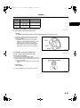
CAMSHAFT INSPECTION
A6E242412420E01
1. Set the No.1 and No.5 journals on V-blocks.
2. Measure the camshaft runout.
• If not as specified, replace the camshaft.
Maximum runout:
0.03 mm {0.0012 in}
AME2224E082
3. Measure the cam lobe height at the two points as
shown.
• If not as specified, replace the camshaft.
AME2224E343
Standard height (mm) {in}
Camshaft
L8
LF, L3
INT
EXH
40.79 {1.606}
41.08 {1.618}
42.12 {1.659}
41.08 {1.618}
L3 (with
variable
valve timing
mechanism)
42.44 {1.671}
41.18 {1.622}
Minimum height (mm) {in}
Camshaft
INT
EXH
B–16
L8
LF, L3
40.692
{1.603}
40.982
{1.614}
42.022
{1.655}
40.982
{1.614}
L3 (with
variable
valve timing
mechanism)
42.342
{1.667}
41.082
{1.618}
1731-1E-02C.book
17 ページ
2002年4月26日 金曜日 午前10時30分
ENGINE
4. Measure the journal diameters in X and Y
directions at the two points (A and B) as indicated
in the figure.
• If not as specified, replace the camshaft.
B
Standard diameter:
24.96—24.98 mm {0.9827—0.9834 in}
Minimum diameter:
24.95 mm {0.982 in}
5. Remove the tappet.
6. Position plasticgage atop the journals in the axial
direction.
7. IInstall the camshaft cap. (See B–40 Camshaft Assembly Note.)
8. Remove the camshaft cap. (See B–6 Camshaft Cap Disassembly Note.)
9. Measure the oil clearance.
• If not as specified, replace the cylinder head.
AME2224E344
Standard clearance:
0.04—0.08 mm {0.002—0.003 in}
Maximum clearance:
0.09 mm {0.0035 in}
10. Install the camshaft cap. (See B–40 Camshaft
Assembly Note)
AME2224E307
11. Measure the camshaft end play.
• If not as specified, replace the cylinder head
or camshaft.
Standard end play:
0.09—0.24 mm {0.0035—0.0094 in}
Maximum end play:
0.25 mm {0.0099 in}
12. Remove the camshaft cap. (See B–6 Camshaft
Cap Disassembly Note.)
AME2224E025
End Of Sie
B–17
1731-1E-02C.book
18 ページ
2002年4月26日 金曜日 午前10時30分
ENGINE
TAPPET INSPECTION
A6E242412310E01
1. Measure the tappet hole inner diameter in X and
Y directions at the two points (A and B) shown.
Inner diameter:
31.000—31.030 mm {1.2205—1.2216 in}
AME2224E319
2. Measure the tappet body outer diameter in X and
Y directions at the two points (A and B) shown.
Outer diameter:
30.970—30.980 mm {1.2193—1.2196 in}
3. Subtract the tappet body outer diameter from the
tappet hole inner diameter.
• If not as specified, replace the tappet or
cylinder head.
Clearance
Standard:
0.02—0.06 mm {0.0008—0.0023 in}
AME2224E320
Maximum:
0.15 mm {0.006 in}
End Of Sie
CYLINDER BLOCK INSPECTION
A6E242410300E01
1. Measure the distortion of the cylinder block top
surface in the six directions as indicated in the
figure.
• If the distortion exceeds the maximum,
replace the cylinder block.
Maximum cylinder block distortion:
0.10 mm {0.004 in}
AME2224E089
2. Measure the cylinder bores in X and Y directions
at 42 mm {1.65 in} below the top surface.
• If the cylinder bore exceeds the wear limit,
replace the cylinder block.
Standard diameter limit
L8:
83.000—83.030 mm {3.2677—3.2689 in}
LF, L3, L3 (with variable valve timing
mechanism):
87.500—87.530 mm {3.4449—3.4460 in}
Minimum / maximum bore diameter limit
L8:
82.940—83.090 mm {3.2653—3.2712 in}
LF, L3, L3 (with variable valve timing mechanism):
87.440—87.590 mm {3.4425—3.4484 in}
B–18
AME2224E090
1731-1E-02C.book
19 ページ
2002年4月26日 金曜日 午前10時30分
ENGINE
End
Of Sie
OIL JET
VALVE INSPECTION
A6E242410730E02
1. Apply compressed air to oil jet valve A and verify
that air passes through oil jet valve B.
• If not ventilation,replace the oil jet valve.
B
Air pressure:
216—274 kPa {2.2—2.7kgf•cm2 31.4—39.7
psi}
AME2224E105
End Of Sie
PISTON INSPECTION
A6E242411010E01
Caution
• The piston, piston ring and connecting rod cannot be disassembled.
• When replacing the piston, piston pin, piston ring and connecting rod, replace them together as a
single unit.
1. Measure the outer diameter of each piston at right
angle 90° to the piston pin, 10.0 mm {0.40 in}
above the under of the piston.
• If the piston diameter is below the standard
diameter, replace the piston, piston pin, piston
ring and connecting rod as a single unit.
Piston diameter
L8:
82.965—82.995 mm {3.2664—3.2675 in}
LF, L3, L3 (with variable valve timing
mechanism):
87.465—87.495 mm {3.4435—3.4446 in}
AME2224E030
2. Measure the piston-to-cylinder clearance.
• If not as specified, replace the piston, piston pin, piston ring and connecting rod as a single unit.
Standard clearance:
0.025—0.045 mm {0.0010—0.0017 in}
Maximum clearance:
0.11 mm {0.0043 in}
3. Measure the piston ring-to-ring groove clearance
around the entire circumference.
• If the piston ring-to-ring groove clearance
exceeds the maximum clearance, replace the
piston, piston pin, piston ring and connecting
rod as a single unit.
Standard clearance:
Top: 0.03—0.08 mm {0.0012—0.0031 in}
Second: 0.03—0.07 mm {0.0012—0.0027in}
Oil: 0.03—0.07 mm {0.0012—0.0027 in}
Maximum clearance:
Top: 0.17 mm {0.0067 in}
Second, Oil: 0.15 mm {0.0059 in}
AME2224E029
B–19
1731-1E-02C.book
20 ページ
2002年4月26日 金曜日 午前10時30分
ENGINE
4. Insert the piston ring into the cylinder by hand and
use the piston to push it to the bottom of the ring
travel.
5. Measure each piston ring end gap with a feeler
gauge.
• If the piston ring end gap exceeds the
maximum end gap, replace the piston, piston
pin, piston ring and connecting rod as a single
unit.
Standard end gap:
Top: 0.16—0.31 mm {0.0063—0.012 in}
Second: 0.33—0.48 mm {0.0130—0.0189 in}
Oil (rail): 0.20—0.70 mm {0.0079—0.0275 in}
AME2224E104
Maximum end gap:
1.0 mm {0.0393 in}
End Of Sie
CRANKSHAFT INSPECTION
A6E242411301E01
1. Install the main bearing cap. (See B–30 Main Bearing Caps Assembly Note.)
2. Measure the crankshaft end play.
• If not as specified, replace the thrust bearing
or crankshaft so that the specified end play is
obtained.
Standard end play:
0.22—0.45 mm {0.0087—0.0177 in}
Maximum end play:
0.55 mm {0.022 in}
3. Remove the main bearing cap. (See B–11 Main
Bearing Cap Disassembly Note.)
4. Measure the crankshaft runout.
• If the crankshaft runout exceeds the maximum runout, replace the crankshaft.
AME2224E034
Maximum runout:
0.05 mm {0.0019 in}
L8, LF
L3, L3 (with variable valve timing mechanism)
AME2224E035
AME2224E311
B–20
1731-1E-02C.book
21 ページ
2002年4月26日 金曜日 午前10時30分
ENGINE
5. Measure the journal diameter in X and Y
directions at the two points (A and B) as indicated
in the figure.
• If not as specified, replace the crankshaft or
grind the journal and install the undersize
bearing.
B
Main journal
mm {in}
Bearing size
Standard
0.25 {0.01}
undersize
Standard diameter
51.980—52.000 {2.0464—2.0472}
51.730—51.750 {2.0366—2.0373}
AME2224E036
Maximum out-of-round:
0.05 mm {0.0019 in}
Crank pin
mm {in}
Bearing size
Standard
0.25 {0.01}
undersize
Standard diameter
49.980—50.000 {1.9677—1.9685}
49.730—49.750 {1.9579—1.9586}
Maximum out-of-round:
0.05 mm {0.0019 in}
6.
7.
8.
9.
10.
Install the main bearing caps and crankshaft.
Position a plastigage atop the journals in the axial direction.
Install the main bearing caps and cylinder block. (See B–30 Main Bearing Caps Assembly Note.)
Remove the main bearing caps. (See B–11 Main Bearing Cap Disassembly Note.)
Measure the main journal oil clearance.
• If the clearance exceeds the maximum,
replace the main bearing using the main
bearing selection table or grind the main
journal and install the oversize bearings so
that the specified oil clearance is obtained.
Standard clearance:
0.019—0.035 mm {0.0007—0.0013 in}
Maximum clearance:
0.10 mm {0.0039 in}
AME2224E038
mm {in}
Bearing
Color
Bearing thickness
size
Standard Green 2.506—2.509 {0.0987—0.0988}
0.25 {0.01}
2.628—2.634 {0.1034—0.1037}
oversize
0.50 {0.02}
2.753—2.759 {0.1084—0.1086}
oversize
B–21
1731-1E-02C.book
22 ページ
2002年4月26日 金曜日 午前10時30分
ENGINE
End
Of Sie
CONNECTING
ROD INSPECTION
A6E242411211E01
Caution
• The piston, piston ring and connecting rod cannot be disassembled.
• When replacing the piston, piston pin, piston ring and connecting rod, replace them together as a
single unit.
1. Install the connecting rod cap. (See B–31 Connecting Rod Cap Assembly Note.)
2. Measure the connecting rod large end side
clearance.
• If the connecting rod large end side clearance
exceeds the maximum clearance, replace the
piston, piston pin, piston ring and connecting
rod as a single unit.
Standard clearance:
0.14—0.36 mm {0.0056—0.0141 in}
Maximum clearance:
0.435 mm {0.0172 in}
3.
4.
5.
6.
7.
AME2224E059
Remove the connecting rod cap.
Position plastigage atop the journals in the axial direction.
Install the connecting rod bearing and connecting rod cap. (See B–31 Connecting Rod Cap Assembly Note.)
Remove the connecting rod cap.
Measure the connecting rod oil clearance.
• If not as specified, replace the connecting rod
bearing or grind the crank pin and use
oversize bearings so that the specified
clearance is obtained.
Standard clearance:
0.026—0.052 mm {0.0011—0.0020 in}
Maximum clearance:
0.1 mm {0.0039 in}
mm {in}
Bearing size
Color
Standard
Green
0.50 {0.02}
oversize
0.25 {0.01}
oversize
AME2224E310
Bearing thickness
1.496—1.502
{0.0589—0.0591}
1.748—1.754 {0.0688—0.0690}
1.623—1.629 {0.0639—0.0641}
End Of Sie
BOLT INSPECTION
A6E242410135E01
1. Measure the length of each bolt.
• Replace any that exceeds maximum length.
AME2224E050
B–22
1731-1E-02C.book
23 ページ
2002年4月26日 金曜日 午前10時30分
ENGINE
Length L
bolt
Cylinder
head bolt
Connecting
rod bolt
Main bearing
cap bolt
Standard (mm) {in} Maximum (mm) {in}
149.0—150
150.5 {5.92}
{5.86—5.90}
44.7—45.3
46.0 {1.81}
{1.75—1.78}
110.0—110.6
111.3 {4.38}
{4.33—4.35}
B
End Of Sie
VARIABLE VALVE TIMING ACTUATOR INSPECTION
A6E242400142E02
L3 (with variable valve timing mechanism)
Caution
• Variable valve timing actuator can not be disassembled it is a precision unit /
1. Confirm that notch of the rotor and bump of the
cover at the variable valve timing actuator are
aligned and fitted.
• If the notch and the bump are not aligned,
rotate the rotor toward the bulb timing retard
position by hand until they are in place.
• If the rotor and cover are not secured even
though their notch and groove are aligned,
replace the variable valve timing actuator.
AME2224E342
End Of Sie
OIL CONTROL VALVE (OCV) INSPECTION
A6E242414420E02
L3 (with variable valve timing mechanism)
Coil resistance inspection
1. Disconnect the negative battery cable.
2. Disconnect the oil control valve (OCV) connector.
3. Measure the resistance between terminals A and
B using an ohmmeter.
• If not as specified, replace the oil control valve
(OCV).
Specification
6.9—7.9 ohms
4. Connect the oil control valve (OCV) connector.
A6E2226W002
B–23
1731-1E-02C.book
24 ページ
2002年4月26日 金曜日 午前10時30分
ENGINE
Spool valve operation inspection
1. Disconnect the negative battery cable.
2. Remove the oil control valve (OCV).
3. Verify that the spool valve in the oil control valve
(OCV) is in the maximum valve timing retard
position as indicated in the figure.
• If not as specified, replace the oil control valve
(OCV).
4. Verify that the battery is fully charged.
• If not as specified, recharge the battery.
AME2226W003
5. Apply battery positive voltage between the oil
control valve (OCV) terminals and verify that the
spool valve operates and moves to the maximum
valve timing advance position.
• If not as specified, replace the oil control valve
(OCV).
Note
• When applying battery positive voltage
between the oil control valve (OCV)
terminals, the connection can be either of
the following:
— Positive battery cable to terminal A,
negative battery cable to terminal B
— Positive battery cable to terminal B, negative battery cable to terminal A
AME2226W004
6. Stop applying battery positive voltage and verify that the spool valve returns to the maximum valve timing
retard position.
• If not as specified, replace the oil control valve (OCV).
End Of Sie
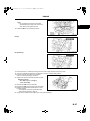
VALVE CLEARANCE INSPECTION
A6E242412111E02
1. Measure the valve clearance as follows.
(1) Turn the crankshaft clockwise so that the
No.1 piston is at TDC of the compression
stroke.
(2) Measure the valve clearance at A in the
figure.
• If the valve clearance exceeds the space
the tappet. (See B–25 VALVE
CLEARANCE ADJUSTMENT.)
Note
• Make sure to note the measured values for
choosing the suitable replacement tappets.
AME2212W001
Standard [Engine cold]
IN: 0.22—0.28 mm {0.0087—0.0110 in} (0.25±
±0.03 mm {0.0098±
±0.0011 in})
EX: 0.27—0.33 mm {0.0106—0.0130 in} (0.30±
±0.03 mm {0.0118±
±0.0011 in})
(3) Turn the crankshaft 360°° clockwise so that the No.4 piston is at TDC of the compression stroke.
(4) Measure the valve clearance at B in the figure.
• If the valve clearance exceeds the standard, replace the tappet. (See B–25 VALVE CLEARANCE
ADJUSTMENT.)
Note
• Make sure to note the measured values for choosing the suitable replacement tappets.
Standard [Engine cold]
IN: 0.22—0.28 mm {0.0087—0.0110 in} (0.25±
±0.03 mm {0.0098±
±0.0011 in})
EX: 0.27—0.33 mm {0.0106—0.0130 in} (0.30±
±0.03 mm {0.0118±
±0.0011 in})
B–24
1731-1E-02C.book
25 ページ
2002年4月26日 金曜日 午前10時30分
ENGINE
End
Of CLEARANCE
Sie
VALVE
ADJUSTMENT
A6E242412111E03
1. Remove the engine front cover lower blind plug.
2. Remove the engine front cover upper blind plug.
3. Remove the cylinder block lower blind plug.
B
AMJ2212E004
4. Install the SST as shown.
5. Turn the crankshaft clockwise the crankshaft is in
the No.1 cylinder TDC position.
AME2212W004
6. Loosen the timing chain.
(1) Using a suitable screwdriver or equivalent
tool, unlock the chain tensioner ratchet.
(2) Turn the exhaust camshaft clockwise using a
suitable wrench on the cast hexagon and
loosened the timing chain.
(3) Placing the suitable bolt (M6 X 1.0 Length
25—35 mm {0.9—1.3 in}) at the engine front
cover upper blind plug, secure the chain
guide at the position where the tension is
released.
AME2212W005
B–25
1731-1E-02C.book
26 ページ
2002年4月26日 金曜日 午前10時30分
ENGINE
7. Hold the exhaust camshaft using a suitable
wrench on the cast hexagon as shown.
AME2212W006
8. Remove the exhaust camshaft sprocket.
AME2212W007
9. Loosen the camshaft cap bolts in several passes
in the order shown.
Note
• The cylinder head and the camshaft caps
are numbered to make sure they are
reassembled in their original position. When
removed, keep the caps with the cylinder
head they were removed from. Do not mix
the caps.
10. Remove the camshaft.
11. Remove the tappet.
12. Select proper adjustment shim.
AME2212W008
New adjustment shim
= Removed shim thickness + Measured valve clearance - Standard valve clearance (IN: 0.25 mm
{0.0098 in}, EX: 0.30 mm {0.0118 in})
Standard [Engine cold]
IN: 0.22—0.28 mm {0.0087—0.0110 in} (0.25±
±0.03 mm {0.0098±
±0.0011 in})
EX: 0.27—0.33 mm {0.0106—0.0130 in} (0.30±
±0.03 mm {0.0118±
±0.0011 in})
13. Install the camshaft with No.1 cylinder aligned with the TDC position.
14. Tighten the camshaft cap bolt using the following
two steps.
(1) Tighten to 5.0—9.0 N·m {51.0—91.7 kgf·cm,
44.3—79.5 in·lbf}.
(2) Tighten to 14.0—17.0 N·m {1.5—1.7 kgf·m,
10.4—12.5 ft·lbf}.
AME2212W009
B–26
1731-1E-02C.book
27 ページ
2002年4月26日 金曜日 午前10時30分
ENGINE
15. Install the exhaust camshaft sprocket.
Note
• Do not tighten the bolt for the camshaft
sprocket during this step. First confirm the
valve timing, then tighten the bolt.
B
16. Install the SST to the camshaft as shown.
AME2212W007
Europe
AME2212W010
Except Europe
AME2212W011
17. Remove the M6 x 1.0 bolt from the engine front cover to apply tension to the timing chain.
18. Turn the crankshaft clockwise the crankshaft is in the No.1 cylinder TDC position.
19. Hold the exhaust camshaft using a suitable
wrench on the cast hexagon as shown.
20. Tighten the exhaust camshaft sprocket lock bolt
Tightening torque
69—75 N·m {7.10—7.6 kgf·m,
50.9—55.3 ft·lbf}
21. Remove the SST from the camshaft.
22. Remove the SST from the block lower blind plug.
23. Rotate the crankshaft clockwise two turns until
the TDC position.
• If not aligned, loosen the crankshaft pulley
lock bolt and repeat from Step 14.
24. Apply silicone sealant to the engine front cover upper blind plug.
AME2212W006
B–27
1731-1E-02C.book
28 ページ
2002年4月26日 金曜日 午前10時30分
ENGINE
25. Install the engine front cover upper blind plug.
Tightening torque:
10 N·m {1.0 kgf·m, 7.4 ft·lbf}
AME2212W003
26. Install the cylinder block lower blind plug.
Tightening torque:
20 N·m {2.0 kgf·m, 14.8 ft·lbf}
AME2212W012
27. Install the new engine front cover lower blind
plug.
Tightening torque:
12 N·m {1.2 kgf·m, 8.9 ft·lbf}
AME2212W002
End Of Sie
B–28
1731-1E-02C.book
29 ページ
2002年4月26日 金曜日 午前10時30分
ENGINE
CYLINDER BLOCK (I) ASSEMBLY
A6E242402000E09
1. Assemble in the order indicated in the table.
2.
B
AME2224E039
.
1
2
3
4
5
6
7
Oil jet valve
Upper main bearing, thrust bearing
Crankshaft
Lower main bearing, thrust bearing
Main bearing cap
(See B–30 Main Bearing Caps Assembly Note)
Piston ring
(See B–30 Piston Ring Assembly Note)
Connecting rod, Piston assembly
(See B–30 Piston Assembly Note)
8
9
10
11
12
Upper connecting rod bearing
(See B–31 Connecting Rod Bearing Assembly
Note)
Lower connecting rod bearing
(See B–31 Connecting Rod Bearing Assembly
Note)
Connecting rod cap
(See B–31 Connecting Rod Cap Assembly Note)
Engine balancer (L3 (with variable valve timing
mechanism))
(See B–31 Balancer Unit Assembly Note)
Adjustment shim
B–29
1731-1E-02C.book
30 ページ
2002年4月26日 金曜日 午前10時30分
ENGINE
Main Bearing Caps Assembly Note
1. Install the main bearing caps in the order
indicated in the figure.
Tightening torque:
(1) 44—46 N·m
{4.5—4.6 kgf·m, 32.5—33.9 ft·lbf}
(2) 175°°—185°°
AME2224E052
Piston Ring Assembly Note
1. Install the two oil control ring segments and
spacer.
2. Verify that the second ring is installed with
scraper face side downward.
3. Verify that the top ring is installed with scraper
face side inner of upper.
AME2224E322
Piston Assembly Note
1. Position the end gap of each ring as indicated in
the figure.
AME2224E323
2. Insert the piston and connecting rod into the
cylinder with the arrow mark to front of the engine.
AME2224E042
B–30
1731-1E-02C.book
31 ページ
2002年4月26日 金曜日 午前10時30分
ENGINE
Connecting Rod Bearing Assembly Note
1. Install the connecting rod bearing to the
connecting rod and connecting rod caps, as
shown in the figure.
B
AME2224E053
Connecting Rod Cap Assembly Note
Caution
• When assembling the connecting rod caps, align the broken, rough faces of the connecting rods
and connecting rod caps.
1. Tighten the connecting rod bolts in two steps.
Tightening torque:
(1) 26—32 N·m
{2.7—3.2 kgf·m, 19.2—23.6 ft·lbf}
(2) 80°°—100°°
Balancer Unit Assembly Note
1. Confirm by visual inspection that there is no damage to the balancer unit gear and verify that the shaft turns
smoothly.
• If there is any damage or malfunction, replace the balancer unit.
Caution
• Due to the precision interior construction of the balancer unit, it cannot be disassembled.
2. Rotate the crankshaft clockwise and align the No. 1 cylinder to the TDC.
3. Install the adjustment shim to the seat face of the balancer unit.
4. With the balancer unit marks at the exact top
center, assemble the unit to the cylinder block.
AME2224E061
5. Insert a screwdriver into the crankshaft No. 1
crankweight area and set both the rotation and
the thrust direction with the screwdriver, using a
prying action, as shown.
AME2224E080
B–31
1731-1E-02C.book
32 ページ
2002年4月26日 金曜日 午前10時30分
ENGINE
6. Set the SST as shown, then measure the gear
backlash using a dial gauge.
• If the backlash exceeds the specified range,
remeasure the backlash and, using the
adjustment shim selection table, select the
proper shim, according to the following
procedure.
Caution
• When measuring the backlash, rotate the
crankshaft one full rotation and verify
that it is within the specified range at all
of the following six positions: 10°°, 30°°,
100°°, 190°°, 210°°, 280°° ATDC.
AME2224E060
Value range:
0.005—0.101 mm {0.00019—0.0039 in}
(1) Using master adjustment shim (No.50), assemble the balancer unit to the cylinder block, then measure the
backlash.
(2) Select the proper adjustment shim according to the measured value.
(3) Install the selected adjustment shim to the balancer unit, then assemble the balancer unit to the cylinder
block.
Adjustment shim selection table
Backlash
mm {in}
Selection shim
(No.)
Shim thickness
mm {in}
0.256—0.262
{0.0100—0.01031}
15
1.15 {0.0452}
0.249—0.255
{0.0098—
0.010039}
16
1.16 {0.0456}
0.242—0.248
{0.0096—0.00976}
17
1.17 {0.0460}
0.235—0.241
{0.0093—0.0948}
18
1.18 {0.0464}
19
1.19 {0.0468}
20
1.20 {0.0472}
21
1.21 {0.0476}
22
1.22 {0.0480}
23
1.23 {0.0484}
24
1.24 {0.0488}
25
1.25 {0.492}
26
1.26 {0.496}
0.228—0.234
{0.00897—
0.00921}
0.221—0.227
{0.00870—
0.00893}
0.214—0.220
{0.00842—
0.00874}
0.207—0.213
{0.00814—
0.00838}
0.200—0.206
{0.00787—
0.00811}
0.193—0.199
{0.00759—
0.00783}
0.186—0.192
{0.00732—
0.00755}
0.179—0.185
{0.00704—
0.00728}
B–32
Backlash
mm {in}
0.116—0.122
{0.00456—
0.00480}
0.109—0.115
{0.00429—
0.00452}
0.102—0.108
{0.00401—
0.00425}
0.095—0.101
{0.00374—
0.00397}
0.088—0.094
{0.00346—
0.00370}
0.081—0.087
{0.00318—
0.00342}
0.074—0.080
{0.00291—
0.00314}
0.067—0.073
{0.00263—
0.00287}
0.060—0.066
{0.00236—
0.00259}
0.053—0.059
{0.00208—
0.00232}
0.046—0.052
{0.00181—
0.00204}
0.039—0.045
{0.00153—
0.00177}
Selection shim
(No.)
Shim thickness
mm {in}
35
1.35 {0.0531}
36
1.36 {0.0535}
37
1.37 {0.0539}
38
1.38 {0.0543}
39
1.39 {0.0547}
40
1.40 {0.0551}
41
1.41 {0.0555}
42
1.42 {0.0559}
43
1.43 {0.0562}
44
1.44 {0.0566}
45
1.45 {0.0570}
46
1.46 {0.0574}
1731-1E-02C.book
33 ページ
2002年4月26日 金曜日 午前10時30分
ENGINE
Backlash
mm {in}
0.172—0.178
{0.00677—
0.00700}
0.165—0.171
{0.00649—
0.00673}
Selection shim
(No.)
Shim thickness
mm {in}
27
1.27 {0.499}
28
1.28 {0.503}
0.158—0.164
{0.00622—0.00645
29
1.29 {0.507}
0.151—0.157
{0.00594—
0.00618}
30
1.30 {0.511}
0.144—0.150
{0.0566—0.0590}
31
1.31 {0.515}
32
1.32 {0.519}
33
34
0.137—0.143
{0.00539—
0.00562}
0.130—0.136
{0.00511—
0.00535}
0.123—0.129
{0.00484—
0.00507}
Backlash
mm {in}
0.032—0.038
{0.00125—
0.00149}
0.025—0.031
{0.000984—
0.00122}
0.018—0.024
{0.000708—
0.000944}
0.011—0.017
{0.000433—
0.000669}
0.004—0.010
{0.00015—
0.000393}
Selection shim
(No.)
Shim thickness
mm {in}
47
1.47 {0.0578}
48
1.48 {0.0582}
49
1.49 {0.0586}
50 (master)
1.50 {0.0590}
51
1.51 {0.0594}
0.000—0.004
{0.000—0.000157}
52
1.52 {0.0598}
1.33 {0.523}
0.000—0.000
{0.000—0.000}
53
1.53 {0.0602}
1.34 {0.527}
0.000—0.000
{0.000—0.000}
54
1.54 {0.0606}
B
End Of Sie
B–33
1731-1E-02C.book
34 ページ
2002年4月26日 金曜日 午前10時30分
ENGINE
CYLINDER BLOCK (II) ASSEMBLY
A6E242402000E10
1. Assemble in the order indicated in the table.
2.
AME2224E043
.
B–34
1731-1E-02C.book
35 ページ
2002年4月26日 金曜日 午前10時30分
ENGINE
1
2
3
4
5
6
7
Rear oil seal
(See B–35 Rear Oil Seal Assembly Note)
End plate (MPV)
Flywheel (MTX), Drive plate (ATX) (See B–36 Drive
Plate (ATX), Flywheel (MTX) Assembly Note)
Oil pump
Oil strainer
Water pump
Thermostat
8
9
10
11
12
13
14
15
Oil separator
Knock sensor
Oil cooler
Oil filter adapter
Oil filter
Oil filter cover
Oil pan
(See B–36 Oil pan Assembly Note)
MTX
B
Rear Oil Seal Assembly Note
1. Apply silicone sealant to the mating faces as
shown.
Dot diameter:
4.0—6.0 mm {0.16—0.23 in}
2. Apply clean engine oil to the new oil seal lip.
AME2224E325
3. Install the rear oil seal using the installer as
shown.
AME2224E326
4. Tighten the rear oil seal bolts in the order as
shown.
Tightening torque:
8.0—11.5 N·m {81.6—117.2 kgf·m, 70.9—
101.7 in·lbf}
AME2224E002
B–35
1731-1E-02C.book
36 ページ
2002年4月26日 金曜日 午前10時30分
ENGINE
Drive Plate (ATX), Flywheel (MTX) Assembly Note
1. Hold the crankshaft using the SST.
2. Tighten the bolts in the order indicated in the
figure in several passes.
AME2224E102
Oil pan Assembly Note
1. Apply a continuous bead of silicone sealant to the
oil pan as indicated in the figure.
AME2224E555
2. Use a square ruler to unite the oil pan and the
cylinder block junction side on the engine front
cover side.
AME2224E054
B–36
1731-1E-02C.book
37 ページ
2002年4月26日 金曜日 午前10時30分
ENGINE
3. Tighten the rear oil pan bolts in the order as
shown.
Tightening torque:
20—30 N·m {2.1—3.0 kgf·m, 15.2—21.6
in·lbf}
B
AME2224E056
End Of Sie
CYLINDER HEAD (I) ASSEMBLY
A6E242402000E11
1. Assemble in the order indicated in the table.
.
AME2224E044
1
2
3
4
Water outlet case
EGR pipe
Valve seal
(See B–38 Valve Seal Assembly Note)
Valve
5
6
7
8
Valve spring
Upper valve spring seat
Valve keeper
(See B–38 Valve Keeper Assembly Note)
Engine hanger
B–37
1731-1E-02C.book
38 ページ
2002年4月26日 金曜日 午前10時30分
ENGINE
Valve Seal Assembly Note
1. Press the valve seal onto the valve guide by
hand.
2. Lightly tap the SST using a plastic hammer.
AME2224E321
Valve Keeper Assembly Note
1. Install the valve keeper using the SSTs.
AME2224E302
End Of Sie
B–38
1731-1E-02C.book
39 ページ
2002年4月26日 金曜日 午前10時30分
ENGINE
CYLINDER HEAD (II) ASSEMBLY
A6E242402000E12
1. Assemble in the order indicated in the table.
2.
B
AME2224E046
.
1
2
3
4
5
Cylinder head gasket
Cylinder head
Cylinder head bolt
(See B–40 Cylinder Head Bolt Assembly Note)
Tappet
Camshaft
(See B–40 Camshaft Assembly Note)
6
7
8
Camshaft cap
Camshaft sprocket, Variable valve timing actuator
(L3 (with variable valve timing mechanism))
(See B–40 Camshaft Sprocket, Variable Valve
Timing Actuator (L3 (with variable valve timing
mechanism)) Assembly Note)
Oil control valve (OCV) (L3 (with variable valve
timing mechanism))
B–39
1731-1E-02C.book
40 ページ
2002年4月26日 金曜日 午前10時30分
ENGINE
Cylinder Head Bolt Assembly Note
1. Tighten the cylinder head bolts in the order
indicated in the figure in six steps.
(1) Tighten to 5.0 N·m {51 kgf·cm, 44.3 in·lbf}.
(2) Tighten to 13— 17 N·m {1.4 —1.7 kgf·m,
9.6—12.5 ft·lbf}.
(3) Tighten to 44— 46 N·m {4.5 —4.6 kgf·m,
32.5—33.9 ft·lbf}.
(4) Tighten 88°°—92°°.
(5) Tighten 88°°—92°°.
AME2224E047
Camshaft Assembly Note
1. Install the camshaft with No.1 cylinder aligned with TDC position.
2. Tighten the camshaft cap bolt using the following
two steps.
(1) Tighten to 5.0—9.0 N·m {51.0—91.7 kgf·cm,
44.3—79.5 in·lbf}.
(2) Tighten to 14.0—17.0 N·m {1.5—1.7 kgf·m,
10.4—12.5 ft·lbf}.
AME2224E048
Camshaft Sprocket, Variable Valve Timing Actuator (L3 (with variable valve timing mechanism)) Assembly
Note
1. Camshaft sprocket or variable valve timing actuator (L3 (with variable valve timing mechanism)) attachment
bolt is changed into the state of a temporary bundle by hand until it attaches timing chain.
2. The attachment bolt of camshaft sprocket or variable valve timing actuator (L3 (with variable valve timing
mechanism)) is bound tight for timing chain after attachment.
Tightening torque
69—75 N·m {7.10—7.60 kgf·m, 50.9—55.3 ft·lbf}
L8, LF, L3
AME2224E077
L3 (with variable valve timing mechanism)
AME2224E078
B–40
1731-1E-02C.book
41 ページ
2002年4月26日 金曜日 午前10時30分
ENGINE
End
Of Sie
TIMING
CHAIN ASSEMBLY
A6E242402000E13
1. Assemble in the order indicated in the table.
2.
B
AME2224E327
.
1
2
3
4
5
6
7
8
9
10
11
Crankshaft sprocket
Oil pump chain
Oil pump sprocket
(See B–42 Oil Pump Sprocket Assembly Note)
Oil pump chain guide
Oil pump chain tensioner
Seal (L3 (with variable valve timing mechanism))
Timing chain
(See B–42 Timing Chain Aassembly Note)
Chain guide
Tensioner arm
Chain tensioner
Camshaft sprocket, Variable Valve Timing Actuator
(L3 (with variable valve timing mechanism))
(See B–43 Camshaft Sprocket, Variable Valve
Timing Actuator (L3 (with variable valve timing
mechanism)) Assembly Note)
12
13
14
15
16
17
18
19
Front oil seal
(See B–44 Front Oil Seal Aassembly Note)
Engine front cover
(See B–44 Engine Front Cover Aassembly Note)
Drive belt idler pulley
Water pump pulley
Crankshaft pulley
Crankshaft pulley lock bolt
(See B–45 Crankshaft Pulley Lock Bolt Aassembly
Note)
Cylinder head cover
(See B–46 Cylinder Head Cover Aassembly Note)
Spark plug
B–41
1731-1E-02C.book
42 ページ
2002年4月26日 金曜日 午前10時30分
ENGINE
Oil Pump Sprocket Assembly Note
1. Hold the oil pump sprocket using the SST.
AME2224E340
Timing Chain Aassembly Note
1. Install the SST to the camshaft, then align the No. 1 camshaft position with the TDC.
Europe
AME2224E329
Except Europe
AME2224E328
2. Remove the cylinder block lower blind plug.
3. Install the SST as shown.
4. Turn the crankshaft clockwise so that the
crankshaft is in the No.1 cylinder TDC position.
5. Install the timing chain.
AMJ2224E666
B–42
1731-1E-02C.book
43 ページ
2002年4月26日 金曜日 午前10時30分
ENGINE
6. Install the chain tensioner and remove the
retaining wire.
B
AME2224E330
Camshaft Sprocket, Variable Valve Timing Actuator (L3 (with variable valve timing mechanism)) Assembly
Note
1. Hold the camshaft using a suitable wrench on the cast hexagon as shown.
L8, LF, L3
AME2224E077
L3 (with variable valve timing mechanism)
AME2224E078
2. Tighten the camshaft sprocket lock bolt.
Tightening torque: 69—75 N·m {7.10—7.6 kgf·m, 50.9—55.3 ft·lbf}
B–43
1731-1E-02C.book
44 ページ
2002年4月26日 金曜日 午前10時30分
ENGINE
Front Oil Seal Aassembly Note
1. Apply clean engine oil to the oil seal.
2. Push the oil seal slightly in by hand.
3. Compress the oil seal using the SST and a
hammer.
AME2224E331
AME2224E332
Engine Front Cover Aassembly Note
1. Apply silicone sealant to the engine front cover as
shown.
Caution
• Install the cylinder head cover within 10
minutes of applying the silicone sealant.
• Silicone sealant is not need in area C as
indicated below due to an existing. (L3
(with variable valve timing mechanism))
Thickness
A: 2.0—3.0 mm {0.079—0.118 in}
B: 1.5—2.5 mm {0.059—0.098 in}
AME2224E333
B–44
1731-1E-02C.book
45 ページ
2002年4月26日 金曜日 午前10時30分
ENGINE
2. Install the cylinder head cover bolts in the order
as shown.
Bolt No.
Tigtining torque N·m {kgf·m, ft·lbf}
1—18
8.0—11.5 N·m
{81.6—117.2 kgf·cm, 70.9—101.7 in·lbf}
19—22
40—55 {4.1—5.6, 29.7—40.5}
B
AME2224E334
Crankshaft Pulley Lock Bolt Aassembly Note
1. Install the SST to the camshaft as shown.
Europe
AME2224E329
Except Europe
AME2224E328
2. Install the M6 x 1.0 bolt in by hand.
3. Turn the crankshaft clockwise so that the
crankshaft is in the No.1 cylinder TDC position.
AME2224E009
B–45
1731-1E-02C.book
46 ページ
2002年4月26日 金曜日 午前10時30分
ENGINE
4. Hold the crankshaft pully using the SST.
5. Tighten the crankshaft pulley lock bolt in the
following two steps.
(1) Tighten to 96—104 N·m {9.8—10.6 kgf·m,
70.9—76.7 ft·lbf}
(2) Tighten 87°°—93°° .
6. Remove the M6 x 1.0 bolt.
7. Remove the SST from the camshaft.
8. Remove the SST from the block lower blind plug.
9. Rotate the crankshaft clockwise two turns until
the TDC position.
• If not aligned, loosen the crankshaft pulley
lock bolt and repeat from Step 1.
10. Install the cylinder block lower blind plug.
AME2224E015
Tightening torque: 20 N·m {2.0 kgf·m, 14.8 ft·lbf}
Cylinder Head Cover Aassembly Note
1. Apply silicone sealant to the mating faces as
shown.
Caution
• Install the cylinder head cover within 10
minutes of applying the silicone sealant.
Dot diameter: 4.0—6.0 mm {0.16—0.23 in}
2. Install the cylinder head cover with a new gasket.
AME2224E335
3. Tighten the bolts in the order shown.
Tightening torque: 8.0 —12 N·m {81.6—122.3
kgf·cm, 70.9—106.2 in·lbf}
AME2224E336
End Of Sie
B–46
1731-1E-02C.book
1 ページ
2002年4月26日 金曜日 午前10時30分
TECHNICAL DATA
TD
TECHNICAL DATA ............................................. TD-2
ENGINE TECHNICAL DATA ............................ TD-2
TD–1
TD
1731-1E-02C.book
2 ページ
2002年4月26日 金曜日 午前10時30分
TECHNICAL DATA
TECHNICAL DATA
ENGINE TECHNICAL DATA
A6E931001001E01
Engine
Item
Cylinder head
Cylinder head gasket
contact surfaces distortion
Manifold contact surfaces
distortion
L8
LF
(mm {in}) Maximum
(mm {in})
Valve clearance [Engine cold]
L3,
L3 (with variable
valve timing
mechanism)
0.10 {0.004}
Maximum
Maximum grinding
IN
(mm {in})
EX
0.10 {0.004}
0.15 {0.006}
0.22—0.28 {0.0087—0.0110}
0.27—0.33 {0.0106—0.0130}
Valve and valve guide
Standard
Valve stem diameter
(mm {in})
Minimum
Standard
Valve stem to guide
clearance
(mm {in})
Valve length
(mm {in})
Maximum
Standard
Minimum
Valve guide inner diameter
(mm {in}) Standard
Valve guide protrusion
height
(mm {in})
Valve head margin thickness
(mm {in}) Minimum
IN
EX
IN
EX
IN
EX
IN
EX
IN
EX
IN
EX
IN
EX
IN
EX
IN
EX
5.470—5.485 {0.2154—0.2159}
5.465—5.480 {0.2152—0.2157}
5.440 {0.2142}
5.435 {0.2140}
0.024—0.069 {0.0009—0.0027}
0.029—0.074 {0.0012—0.0029}
0.10 {0.004}
0.10 {0.004}
102.99—103.79 {4.055—4.086}
104.25—105.05 {4.105—4.135}
102.99 {4.055}
103.79 {4.086}
5.509—5.539 {0.2169—0.2180}
5.509—5.539 {0.2169—0.2180}
12.2—12.8 {0.481—0.503}
12.2—12.8 {0.481—0.503}
1.62 {0.0637}
1.82 {0.0716}
Valve seat
Valve seat contact width
Valve seat angle
Valve seat sinking
(Valve protrusion height)
Valve spring
Out-of-square
Pressing force at valve
spring height H
OCV (Oil control valve)
Coil resistance [20° C{68°F}]
TD–2
IN
EX
IN
(°)
EX
IN
(mm {in}) Standard
EX
(mm {in}) Standard
(mm {in}) Maximum
H: 27.8 mm
(N {kgf, lbf})
{1.094 in}
(ohm) Standard
1.2—1.6 {0.048—0.062}
1.2—1.6 {0.048—0.062}
45
45
40.64—42.24 {1.600—1.662}
40.50—42.10{1.595—1.657}
1% (2.10 {0.082})
494.9 {50.47,111.2}
–
6.9—7.9 *
1731-1E-02C.book
3 ページ
2002年4月26日 金曜日 午前10時30分
TECHNICAL DATA
Engine
Item
Camshaft
Camshaft runout
L8
LF
(mm {in}) Maximum
0.03 {0.0012}
IN
40.79 {1.606}
42.12{1.659}
EX
41.08 {1.618}
41.08{1.618}
IN
40.692{1.603}
42.022{1.655}
EX
40.982 {1.614}
40.982{1.614}
Standard
Cam lobe height
(mm {in})
Minimum
Journal diameter
Journal oil clearance
End play
Tappet
Tappet bore diameter
Tappet diameter
Tappet-to-Tappet bore oil
clearance
Cylinder block
Cylinder head gasket
contact surfaces distortion
Cylinder bore diameter
[Measure the cylinder bore
at 42 mm
{1.65 in} below the top
surface]
Minimum / maximum bore
diameter Limit
Piston
L3,
L3 (with variable
valve timing
mechanism)
Standard
Minimum
Standard
(mm {in})
Maximum
Standard
(mm {in})
Maximum
(mm {in})
42.12 {1.659}
42.44{1.671}*
41.08 {1.618}
41.18 {1.622}*
42.022{1.655}
42.342 {1.667}*
40.982 {1.614}
41.082 {1.618}*
24.96—24.98 {0.9827—0.9834}
24.95 {0.982}
0.04—0.08 {0.002—0.003}
0.09 {0.0035}
0.09—0.24 {0.0035—0.0094}
0.25 {0.009}
(mm {in}) Standard
(mm {in}) Standard
Standard
(mm {in})
Maximum
31.000—31.030 {1.2205—1.2216}
30.970—30.980 {1.2193—1.2196}
0.02—0.06{0.0008—0.0023}
0.15 {0.006}
(mm {in}) Maximum
0.10 {0.004}
(mm {in}) Standard
(mm {in})
Piston diameter
(mm {in}) Standard
Piston-to-cylinder clearance
(mm {in})
Standard
Maximum
83.000—83.030
{3.2677—3.2689}
87.500—87.530 {3.4449—3.4460}
82.940—83.090
{3.2653—3.2712}
87.440—87.590 {3.4425—3.4484}
82.965—82.995
87.465—87.495 {3.4435—3.4446}
{3.2664—3.2675}
0.025—0.045 {0.0010—0.0017}
0.11 {0.0043}
Piston ring
Top
Second
Oil (rail)
(mm {in})
Top
Maximum Second
Oil (rail)
Top
Standard Second
Oil (rail)
(mm {in})
Top
Maximum Second
Oil (rail)
Standard
Piston ring-to-ring groove
clearance
End gap
(measured in cylinder)
0.03—0.08 {0.0012—0.0031}
0.03—0.07 {0.0012—0.0027}
0.03—0.07 {0.0012—0.0027}
0.17 {0.0067}
0.15 {0.0059}
0.15 {0.0059}
0.16—0.31 {0.0063—0.0122}
0.33—0.48 {0.0130—0.0189}
0.20—0.70 {0.0079—0.0275}
1.0 {0.0393}
1.0 {0.0393}
1.0 {0.0393}
TD–3
TD
1731-1E-02C.book
4 ページ
2002年4月26日 金曜日 午前10時30分
TECHNICAL DATA
Engine
Item
Connecting rod and connecting rod bearing
Standard
Connecting rod side
(mm {in})
clearance
Maximum
Standard
Connecting rod bearing size
(mm {in}) 0.25 {0.01} Oversize
0.50 {0.02} Oversize
Standard
Connecting rod bearing oil
(mm {in})
clearance
Maximum
Crankshaft
Crankshaft runout
(mm {in}) Maximum
Standard
Main journal diameter
(mm {in}) 0.25 {0.01}
undersize
Standard
Main journal oil clearance
(mm {in})
Maximum
Main journal out of round
(mm {in}) Maximum
Standard
Main bearing size
(mm {in}) 0.25 {0.01} Oversize
0.50 {0.02} Oversize
Standard
Crank pin journal diameter
(mm {in}) 0.25 {0.01}
undersize
Crank pin out of round
(mm {in}) Maximum
Standard
Crankshaft end play
(mm {in})
Maximum
Front oil seal
Pushing distance of the front oil seal
(mm {in})
[from the edge of the engine front cover]
Bolt
Standard
Cylinder head bolt length
Maximum
Standard
Connecting rod bolt length
Maximum
Standard
Main bearing cap bolt length
Maximum
Balance shaft
Gear backlash
*:
(mm {in}) Maximum
With variable valve timing mechanism
End Of Sie
TD–4
L8
LF
L3,
L3 (with variable
valve timing
mechanism)
0.14—0.36 {0.0056—0.0141}
0.435 {0.0172}
1.496—1.502 {0.0589—0.0591}
1.623—1.629 {0.0639—0.0641}
1.748—1.754 {0.0688—0.0690}
0.026—0.052{0.0011—0.0020}
0.10{0.0039}
0.05 {0.0019}
51.980—52.000 {2.0464—2.0472}
51.730—51.750 {2.0366—2.0373}
0.019—0.035{0.0007—0.0013}
0.10 {0.0039}
0.05 {0.0019}
2.506—2.509 {0.0987—0.0988}
2.628—2.634 {0.1034—0.1037}
2.753—2.759 {0.1084—0.1086}
49.980—50.000 {1.9677—1.9685}
49.730—49.750 {1.9579—1.9586}
0.05 {0.022}
0.22—0.45{0.0087—0.0177}
0.55 {0.0216}
0—0.5 {0—0.019}
149.0—150.0 {5.86—5.90}
150.5 {5.92}
44.7—45.3 {1.75—1.78}
46.0 {1.81}
110.0—110.6 {4.33—4.35}
111.3 {4.38}
–
0.005-0.101
{0.00019—
0.0039}
1731-1E-02C.book
1 ページ
2002年4月26日 金曜日 午前10時30分
SPECIAL TOOLS
ST
SPECIAL TOOLS .................................................ST-2
ENGINE SST .....................................................ST-2
ST–1
ST
1731-1E-02C.book
2 ページ
2002年4月26日 金曜日 午前10時30分
SPECIAL TOOLS
SPECIAL TOOLS
ENGINE SST
A6E941001001E01
Ford SST numbers are collated with Mazda SST numbers in the example below.
Ford SSTs are marked with Ford SST number.
Example
1:49 JE01 061
2:303-507
Peg
1: Mazda SST number
2: Ford SST number
1:49 JE01 061
2:303–507
1:49 UN20 5072
2:205–072
Peg
Holder
1:49 UN20
507202
2:205–072–02
Adapter
1:49 G032 354
2: –
1:49 E011 1A0
2: –
1:49 0636 100B
2: –
Adjusting
wrench
Ring gear brake
set
Valve spring
lifter arm
1:49 B012 0A2
2: –
1:49 B012 015
2: –
1:49 H010 401
2: –
Pivot
Valve guide
installer
Oil seal installer
1:49 0107 680A
2: –
1:49 L010 1A0
2: –
1:49 S120 170
2: –
Engine stand
Engine hanger
set
Valve seal
remover
1:49 L012 0A0B
2: –
1:49 T032 302
2: –
1:49 D032 316
2: –
Valve seal and
valve guide
installer set
Bearing installer
Protractor
ST–2
1731-1E-02C.book
3 ページ
2002年4月26日 金曜日 午前10時30分
SPECIAL TOOLS
1:49 JE01 054
(Europe)
49 UN30 3376
(Except Europe)
2: 303–376
1:49 G011 201
2: –
Attachment
–
Plate
End Of Sie
ST
ST–3