1
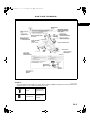
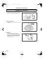
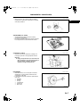
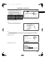
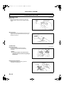
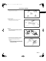
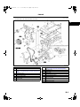
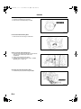
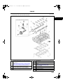
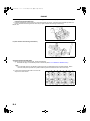
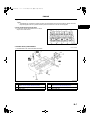
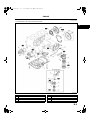
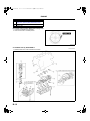
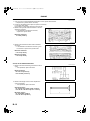
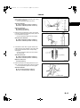
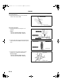
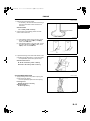
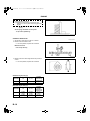
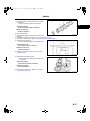
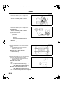
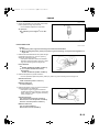
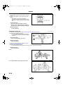
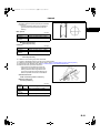
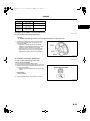
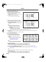
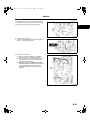
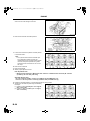
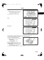
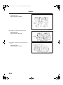
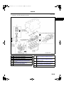
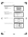
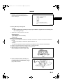
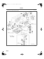
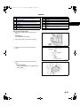
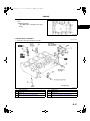
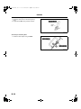
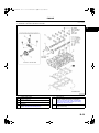
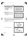
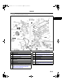
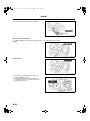
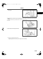
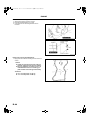
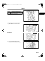
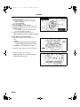
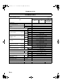
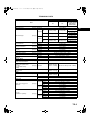
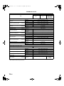
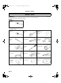
1731-1E-02C.book
11 ページ
2002年4月26日 金曜日 午前10時30分
ENGINE
.
1
2
3
4
5
6
Balancer unit (L3, L3 (with variable valve timing
mechanism))
Connecting rod cap
(See B–11 Connecting Rod Cap Disassembly Note)
Lower connecting rod bearing
Upper connecting rod bearing
Connecting rod, Piston assembly
Piston ring
7
8
9
10
11
12
13
Main bearing cap
(See B–11 Main Bearing Cap Disassembly Note)
Lower main bearing, thrust bearing
Crankshaft
Upper main bearing, thrust bearing
Oil jet valve
Cylinder block
Adjustment shim
Connecting Rod Cap Disassembly Note
1. Inspect the connecting rod side clearance. (See B–22 CONNECTING ROD INSPECTION .)
2. Remove the connecting rod bolt from the connecting rod cap by tapping the bolt with a plastic hammer.
Note
• The tappets are numbered to make sure they are assembled in their original positions. When removed,
keep the tappets with the cylinder head they were removed from. Do not mix the tappets.
Main Bearing Cap Disassembly Note
1. Inspect the crankshaft end play. (See B–20 CRANKSHAFT INSPECTION .)
2. Loosen the main bearing cap bolts in two or three
steps in the order shown.
AME2224E341
End Of Sie
B–11
B