1
CX-A450: Installation and Operation Manual
2
1
Safety Notes
•
•
•
•
•
Do not expose the unit to water or moisture
Do not expose the unit to naked flames.
Do not block or restrict any air vent
Do not operate the unit in ambient temperatures above 35oC
Do not touch any part or terminal carrying the hazardous live symbol ( ) while
power is supplied to the unit.
• Do not perform any internal adjustments unless you are qualified to do so and fully
understand the hazards associated with mains operated equipment.
• The unit has no user serviceable parts. Refer any servicing to qualified service
personnel.
• If the moulded plug is cut off the lead for any reason, the discarded plug is a
potential hazard and should be disposed of in a responsible manner.
For more detailed information refer to the rear of the manual.
2
General
The CX-A450 is a four-channel power amplifier with a typical output of 50 watts per channel
into a 4Ω load. The unit features extremely low distortion and low noise together with a high
slew rate. Full circuit protection is provided and the load is disconnected if the heat sink
overheats or any DC is detected at the output. A five-second switch-on delay operates to
avoid any switching thumps or other extraneous signals reaching the speaker system. The
CX-A450 also has Dynamic Clip Protection (DCP) that will automatically reduce the signal
level when the amplifier is driven into clipping thus limiting any clipping distortion to a low
level.
All four input amplifiers are balanced and have 3-pin plug in screw terminal type input
connectors with adjacent level controls, all mounted on the rear panel. Input signal routing
switches are provided and allow the unit to operate in many configurations whilst retaining
simple input connections.
3
Installation
The CX-A450 is suitable for mounting in a standard 19" equipment rack and occupies two
units of rack space. Sufficient ventilation must be provided for the unit. The amplifier draws
cool air through the front panel and exhausts through the rear panel, care must be taken not
to obstruct the airflow otherwise the unit may intermittently turn off due to the built-in thermal
protection. The unit is 320mm deep but a depth of 400mm should be allowed to clear the
connectors.
4
Input Facilities
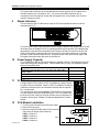
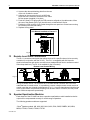
All four inputs are balanced and use 3-pin plug-in screw terminal type connectors (3.5mm
pitch). All inputs have a level control adjacent to their respective connector. Rear panel
mounted switches provide input routing on channels 2, 3 and 4 allowing a variety of
configurations.
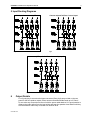
In its default configuration, the unit operates as four independent amplifiers. Two stereo
pairs, driven from one stereo source and four channels driven from one mono source are
also possible by suitably configuring the input routing switches. Schematic diagrams of the
switching network in various configurations can be found on page 3.
07-03-05 V3.0