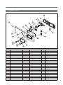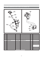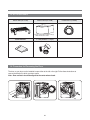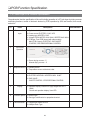
1
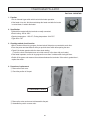
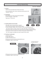
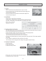
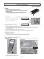
Service Guide
Electric And Gas Dryer
Model : KUD-WG55S
DWR–WG52S
Caution
+PVJKU/CPWCNUQOGRCTVUECPDGEJCPIGFHQTKORTQXKPIVJGKT
performance without notice in the parts list. So, if you need the
latest parts information, please refer to PPL(Parts Price List) in
5GTXKEG+PHQTOCVKQP%GPVGT
JVVRUXEFYGEQMT
80
Contents
PWhat is a Dryer?........................................................................................................................................................ 2
PDryer Specification .................................................................................................................................................... 4
POperating Mechanism Diagram (Gas Type) ............................................................................................................ 5
POperating Mechanism Diagram (Electric Type) ....................................................................................................... 6
PMechanism by Ass’y (Electric Type)......................................................................................................................... 7
PMechanism by Ass’y (Gas Type).............................................................................................................................. 8
PParts List by Ass’y ..................................................................................................................................................... 9
PPCB Function Specification ................................................................................................................................... 23
PDrum Dryer Troubleshooter .................................................................................................................................... 37
PDryer Installation...................................................................................................................................................... 40
PElectrical Requirements For Electric Dryers........................................................................................................ ...41
PDryer Service Notices ............................................................................................................................................ 47
PElectric Parts List – Electric Clothes Dryer ............................................................................................................. 48
PElectric Parts List – Gas Clothes Dryer .................................................................................................................. 49
Thermostat Fan .........................................................................................................................................................................50
Thermostat Cut–Out..................................................................................................................................................................51
Thermostat Hi–Limit ..................................................................................................................................................................52
Lamp Assembly.........................................................................................................................................................................53
Switch Door ...............................................................................................................................................................................54
Heater Assembly .......................................................................................................................................................................55
Belt Switch (Switch Micro).........................................................................................................................................................56
Thermistor Fan ..........................................................................................................................................................................57
Motor Dryer................................................................................................................................................................................58
Igniter As....................................................................................................................................................................................60
Flame Sensor ............................................................................................................................................................................61
Thermostat Hi–Limit ..................................................................................................................................................................62
Thermostat Cut–Out..................................................................................................................................................................63
Valve Gas As.............................................................................................................................................................................64
PDismantling Method Per Dryer Ass'y
PANEL FRONT ASS’Y / PLATE TOP ASS'Y...........................................................................................................................65
CABINET FRONT ASS'Y..........................................................................................................................................................66
FRAME UPPER / SEPARATION OF LAMP,PCB MAIN CONNECTOR ................................................................................67
PCB MAIN / DUCT OUTLET ASS'Y.........................................................................................................................................68
SUPPORT DRUM FRONT ASS'Y / DRUM ASS'Y / PIPE EXHAUST....................................................................................69
COVER BACK / SUPPORT DRUM REAR ASS'Y...................................................................................................................70
MOTOR CONNECTOR ............................................................................................................................................................71
TERMINAL BLOCK...................................................................................................................................................................72
MOTOR ASS'Y..........................................................................................................................................................................73
HEATER ASS'Y / LAMP ASS'Y................................................................................................................................................75
FILTER DUST ASS'Y / HUMIDTY SENSOR ...........................................................................................................................76
DOOR ASS'Y.............................................................................................................................................................................77
GAS BURNER ASS'Y ...............................................................................................................................................................79
RWhat is a Dryer?
1. What is a Dryer?
A lifter, operated by a rotating drum, rolls laundry in the drum, and hot air heated by electricity (or gas) dries
the laundry through time or sensor dry system (a temperature control system) under various conditions.
2. Key Features
※ Note that some features are options.
V Large Capacity/Time–Saving
Ŗ#NCTIGSWCPVKV[QHNCWPFT[ECPDGFTKGFCVCVKOGUCXKPIGPGTI[CUYGNNCUVKOG
V Automatic Digital Dry
Ŗ6JGFKIKVCNUGPUQTOGCUWTGUVJGJWOKFKV[QHNCWPFT[HQTQRVKOWOFT[KPI
V Large Door and Automatic Dry
Ŗ6JGFT[GTJCUCNCTIGVTCPURCTGPVFQQTHQTEQPXGPKGPVNCWPFT[FTQRRKPICPFEJGEMKPI
V Dust Filter
Ŗ(NWHHCPFFWUVCTGHKNVGTGFFWTKPIVJGFT[KPIRTQEGUU
V Sterilizing Dry
Ŗ6JGJKIJŌVGORGTCVWTGCKTFTKGUNCWPFT[YKVJUVGTKNK\KPIGHHGEVU
V Drying Shoes
Ŗ6JGFT[GTTCEMRTQXKFGFYKVJVJGWPKVJGNRUFT[KPIUJQGUCUYGNNCUUGPUKVKXGHCDTKE
V%JKNF.QEM
Ŗ6JKUKUVJGHWPEVKQPVJCVRTQVGEVUEJKNFTGPHTQOJCTOFWTKPIVJGFT[KPIRTQEGUU
2
3. Key Functions
V Time Dry
Ŗ#FLWUVVJGNGPIVJQHVKOGHQTFT[KPI
V Sensor Dry
Ŗ#WVQOCVKECNN[FT[CEEQTFKPIVQVJGV[RGUQHNCWPFT[
V Custom Program
Ŗ4GOGODGTOQUVŌHTGSWGPVN[ŌWUGFFT[KPIEQWTUG
V4CEM&T[
Ŗ&T[UGPUKVKXGHCDTKE
GIUYGCVGTUUKNMNKPIGTKGQPVJGTCEM
V Reduce Static
Ŗ6JKUQRVKQPKPLGEVUUVGCONCVGKPVJGFT[KPIE[ENGVQTGFWEGVJGUVCVKEGNGEVTKEKV[ECWUGFD[FT[HCDTKEU
rubbing together.
V Anti Crease
Ŗ-KNNDCEVGTKCYKVJJKIJŌVGORGTCVWTGCKT
V Damp Dry Beep
Ŗ-GGRNCWPFT[FCORGPQWIJVQDGKTQPGF
3
RDryer Specification
2TQFWEV.QQM
⑫⑯
⑰
⑮
⑭
⑥
⑩
⑧
⑨
④
⑬
⑱
⑪
⑦
①
②
③
⑤
Dimensions
No.
Parts
1
FRAME DOOR O
2
PROTECTOR GLASS
3
DECO FRAME
4
PANEL FRONT
5
CABINET FRONT
6
PLATE TOP
7
CABINET
8
BUTTON POWER
9
BUTTON START
10
WINDOW COURSE
11
BUTTON FUNCTION
12
BUTTON OPTION
13
WINDOW DISPLAY
14
LESS TIME
15
MORE TIME
16
DECO COURSE
17
BUTTON DIAL
18
WINDOW FUNCTION
27" (68.6cm)x 32" (81.2cm)x 40 3/8" (102.5cm)x52” (132cm)
W x D x H x Depth with door open
ND
MI
Weight
Capacity
Rated Power
Rating
IEC 7.3 cu.ft (22.9lb)
Electric
Gas(LNG/LPG)
120/240V 60Hz
120V 60Hz
23.5A 5300W
5A 22.9lb
4
ROperating Mechanism Diagram (Gas Type)
Electric Input
Program
0 Operating Mechanism
Ŗ%QPVTQNNGTQRGTCVKQP
Ŗ1RGTCVQTICUDWTPGTCKTUWRRNKGTXGPVKNCVQTQRGTCVKQP
Ŗ#WVQOCVKEQRGTCVKQPQHVJGEQPVTQNNGT
Ŗ&T[KPID[VJGCWVQOCVKEUGPUQT
lifter
plate top
control pannel
4. Heat Exchanger & Dryer
Ŗ&47/
Ŗ.+(6'4
Ŗ&T[KPIVGORGTCVWTGUGPUQT
1. Controller
Ŗ/#+02%$
Ŗ(41062%$
Ŗ*#40'55
Ŗ219'4%147#
Steam AS
duct inlet
door
Laundry
cabinet front
filter as
3. Gas Burner
Ŗ)CU8CNXG#5
.0).2)
Ŗ6*'4/156#6
duct outlet
impeller fan
5. FILTERING
Ŗ(+.6'4#55;
6. Air–Ventilator
Ŗ#KTŌXGPVFWEV
2. Drive
Ŗ+/2'..'4(#0
Ŗ/1614#55;
Ŗ6*'4/156#6
Ŗ$'.6+&.'4#55;
5
ROperating Mechanism Diagram (Electric Type)
Electric Input
Program
0 Operating Mechanism
Ŗ%QPVTQNNGTQRGTCVKQP
Ŗ1RGTCVQTJGCVGTCKTUWRRNKGTXGPVKNCVQTQRGTCVKQP
Ŗ#WVQOCVKEQRGTCVKQPQHVJGEQPVTQNNGT
Ŗ&T[KPID[VJGCWVQOCVKEUGPUQT
lifter
plate top
Steam AS
control pannel
4. Heat Exchanger & Dryer
Ŗ&47/
Ŗ.+(6'4
Ŗ&T[KPIVGORGTCVWTGUGPUQT
1. Controller
Ŗ/#+02%$
Ŗ(41062%$
Ŗ*#40'55
Ŗ6'4/+0#.$.#%-
(240V 60Hz)
duct inlet
door
Laundry
heater as
cabinet front
filter as
impeller fan
duct outlet
5. FILTERING
Ŗ(+.6'4#55;
3. Heater
Ŗ*'#6'4
ASS'Y(5KW)
Ŗ6*'4/156#6
Ŗ&7%6+0.'6
6. Air–Ventilator
Ŗ#KTŌXGPVFWEV
2. Drive
Ŗ+/2'..'4(#0
Ŗ/1614#55;
Ŗ6*'4/156#6
Ŗ$'.6+&.'4#55;
6
RMechanism by Ass’y (Electric Type)
PLATE TOP ASS'Y
MAIN PCB ASS'Y
CABINET ASS'Y
DRUM SUPPORT
REAR ASS'Y
PANEL F ASS'Y
DUCT IN LET
ASS'Y
DRUM SUPPORT
FRONT ASS'Y
MOTOR ASS'Y
CABINET F ASS'Y
7
DRUM ASS'Y
RMechanism by Ass’y (Gas Type)
PLATE TOP ASS'Y
MAIN PCB ASS'Y
CABINET ASS'Y
DRUM SUPPORT
REAR ASS'Y
PANEL F ASS'Y
DUCT IN LET
ASS'Y
DRUM SUPPORT
FRONT ASS'Y
CABINET F ASS'Y
GAS BURNER
ASS'Y
8
DRUM ASS'Y
RParts List by Ass’y
1. DRYER CBINET ASS'Y
9
No.
Part Code
Description
Qtt’y
CABINET(ELECTRIC)
3610812350
SGCC 0.8T
1
CABINET(GAS)
3610812360
SGCC 0.8T
1
C01–1 FRAME TOP L
3612206500
SGCC 1.6T
1
C01–2 FRAME TOP R
3612206600
SGCC 1.6T
1
C01–3 BASE UNDER
3610392900
SGCD 0.8T
1
C01
Part Name
C02
LOCK HARNESS M
3612207900
NYLON
12
C03
FRAME UPPER
3612207900
SGCC 1.2T
1
SCREW TAPPING
7121401411
T2S TRS 4x14
6
COVER BACK
3611427900
SGCC 0.6T
1
SCREW TAPPING
7112401411
T1 TRS 4x14
12
C05
COVER DUCT
3611428010
ABS
2
C06
FIXTURE PLATE
3612008000
POM
6
–
SCREW TAPPING
7121401211
T2S PAN 4x12
6
C07
SUPPORTER LEG F
3615304200
SECC 3.0T
2
C08
SUPPORTER LEG R
3615304300
SECC 3.0T
2
C09
FIXTURE LEG
3612006400
ABS
4
C10
FOOT
3612100700
BUTYL
4
SCREW TAPPING
7122401411
T2S TRS 4x14
2
–
C04
–
–
C11
–
C12
PCB DRYER MAIN AS
SCREW TAPPING
HARNESS AS
PRPSSWAD44 UL, Electric main, Hot steam
1
PRPSSWAD43 UL, Electric main, Cold steam
1
PRPSSWAD47
UL, Gas main, Hot steam
1
PRPSSWAD46
UL, Gas main, Cold steam
1
7122401411
T2S TRS 4x14
2
3612799100
UL, Electric main, Hot steam
1
3612799000
UL, Electric main, Cold steam
1
3612797320
UL, Gas main, Hot steam
1
3612797330
UL, Gas main, Cold steam
1
Remark
1 PIECE SVC PART
(QTſZKPI(TCOG7RRGTVQ%CDKPGV
(QTſZKPI%QXGT$CEM
(QTſZKPI2NCVG
(QTſZKPI5WRRQTVGT.GI(4
(QTſZKPI/CKP2%$VQ%CDKPGV
–
SCREW TAPPING
7121401411
T2S TRS 4x14
6
(QTſZKPI6GTOKPCN$NQEM
–
SPECIAL SCREW
7S422X4081
TT3 TRS 4x8 SE MFZN
2
(QTſZKPI'CTVJ9KTG
C13
COVER TERMINAL
3611428100
SGCC 1.0T
1
–
SCREW TAPPING
7112401411
T1 TRS 4x14
1
C14
PIPE EXHAUST AS
3614413600
SGCC 0.5T
1
–
SCREW TAPPING
7112401008
T1 TRS 4x14
1
UNIT STEAM AS
3619606700
UNIT STEAM AS
1
SCREW TAPPING
7122401411
T2 TRS 4*14
2
C15
–
10
(QTſZKPI%QXGT6GTOKPCN
(QTſZKPI2KRG'ZJCWUV#5
(QTſZKPI5VGCO#5
2. DRYER MOTOR ASS'Y
M03
M07
M04
M02
M06
M01
M09
M14
M05
M15
M12
M11
M08
M10
M13
M16
No.
Description
Qtt’y
BRACKET MOTOR
3610608500
SGCC 2.0T
1
M02
MOTOR DRYER
36189L5D00
AC 120V 60Hz
1
M03
CLAMP MOTOR
3611206000
SK5 0.7T
2
M04
BRACKET IDLER AS
3610609100
DWR–WE31
1
M05
SPRING IDLER
3615115500
HSW3
1
M06
SPECIAL BOLT
3616039000
S18A M6x10(FLANGE)
1
M07
SWITCH MICRO
3619047500
UL. 16A 250AC HINGE LEVER. N–C 200G
1
5%4'96#22+0)
652#0Z
M08
Ō
CASE FAN F
3611144900
PP(Heat resisting)
1
M09
CASE FAN R
3611145000
PP(Heat resisting)
1
GASKET PIPE
3612323200
EPDM(320*15*2.0t)
1
SCREW TAPPING
7112401411
T1 TRS 4x14
3
–
Part Code
M01
M10
Part Name
M11
THERMOSTAT FAN
3619047900
UL.70ON.85OFF.125V/15A,250V/7.5A
1
Ō
5%4'96#22+0)
652#0Z
M12
THERMISTOR FAN
361AAAAC20
UL–DRYER.R40=26.065K.R90=4.4278K
1
Ō
5%4'96#22+0)
6645Z
M13
IMPELLER FAN AS
3611886200
PP(Heat resisting)+BUSHING
1
M14
SPECIAL WASHER
3616039100
SPC
1
M15
SPECIAL NUT
3616039200
NUT HEX 3/8–24 UNF LH
1
M16
COVER FAN
3611428200
PP(Heat resisting)
1
5%4'96#22+0)
6645Z
Ō
11
Remark
(QTſZKPIOKETFUY
(QTſZKPIECUGHCPTVQDTCEMGVOQVQT
(QTſZKPIVJGTOQUVCVHCP
(QTſZKPIVJGTOKUVQTHCP
(QTſZKPIEQXGTHCP
3. GAS BURNER ASS'Y
No.
G01
Part Name
VALVE AS
Part Code
Description
Qtt’y
Remark
3615417200
DC12V,130mA 0.5Psi
1
LPG
3615417300
DC12V,130mA 0.5Psi
1
LNG
(QTſZKPI))
)
5%4'96#22+0)
6/
G03
GUIDE BUNNER
3612511100
SGCC 1.0T
1
G04
MIXING VENTURI AS
3612209200
VENTURI AS+ FLAME DAMPER
1
G05
SCREW TAPPING
M4*8, T1
2
G06 B
RACKET IGNITER
SGCC 1.6T
1
3610609400
WELDING(SPOT)
)
5%4'96#22+0)
6/uÓ
(QTſZKPI))
)
5%4'96#22+0)
6/uÓ
(QTſZKPI))
G09
IGNITER AS
36189L5800
Ceramic type 120V 60Hz 4A
1
G10
O–RING
3614604100
HNBR
1
G11
PIPE AS
3614413800
Pipe+Fixture+connector
1
WELDING
(QTſZKPI))
)
5%4'96#22+0)
G13
CAP PIPE
259uÓ
3610918200
PP
1
G14
G15
FIXTURE FUNNEL
3612009200
SGCC 2.0T
1
FUNNEL
3612511300
ALCOSTA 0.7T
1
)
5%4'96#22+0)
6/
G17
FLAME SENSOR AS
3614825700
G18
SCREW TAPPING
G19
THERMOSTAT CUT–OUT 3619047810
110°C OFF / – 35°C ON
1
G20
SCREW TAPPING
T1 M4*8
2
G21
THERMOSTAT HI–LIMIT 3619047610
95°C OFF / 70°C ON 125V 25A
1
G22
SCREW TAPPING
T1 M4*8
2
CSA, 5.75A 120V 60Hz 10RS
1
T1 M4*8
1
12
(QTſZKPI))
4. INLETDUCT ASS'Y
4–1. Electric Type
A01
4–2. Gas Type
A02
A04
A05
A06
A03
No.
Part Name
Part Code
A01
DUCT INLET REAR
3617510200
Description
3617510210
ALCOSTA 0.6T
1
GAS TYPE
A02
DUCT INLET FRONT
3617510300
ALCOSTA 0.6T
1
ELECTRIC TYPE
3617510310
ALCOSTA 0.6T
1
GAS TYPE
ALCOSTA 0.6T
Qtt’y
Remark
1
ELECTRIC TYPE
A03
HEATER AS
3612802500
240V 5000W
1
ELECTRIC TYPE
A04
THERMOSTAT HI–LIMIT
3619047600
125°C OFF / 94°C ON 250V 25A
1
ELECTRIC TYPE
A05
THERMOSTAT CUT–OUT
3619047800
140°C OFF / –35°C ON 250V 25A
1
ELECTRIC TYPE
A06
HARNES HEATER(DRYER)
3612797100
UL1015 AWG12
1
ELECTRIC TYPE
Ō
5%4'96#22+0)
65645Z/(<0
(14(+:+0)&7%6+0.'6(4
–
SCREW TAPPING
7122400811
T2S TRS 4x8 MFZN
4
FOR FIXING SENSOR
13
5. SUPPORT DRUM REAR ASS'Y
B07
B02
B03
B01
B02
B04
B05
No.
B01
Part Name
SUPPORT DRUM REAR
Part Code
Description
3615304500
STS430 2B 0.8T
3615304550
ALCOSTA,SA1D 0.8T,DRYER
B02
Qtt’y
Remark
1
B02
BRACKET SUP.R–SIDE
3610608810
SGCC 1.0t
2
B03
BRACKET SUP.R–UPPER
3610608910
SGCC 1.0t
1
Ō
5%4'96#22+0)
6645Z/(<0
B04
ROLLER AS
(QTſZKPIDTCEMGVUWRRWRUKFG
3614714400
ASSY
2
$ 9#5*'45*#(6
6+&1&
(QTſZKPITQNNGTCU
$
076*':
/2
(QTſZKPITQNNGTCU
B07
DUCT INLET AS
3617510110
ALCOSTA 0.6T
1
GAS TYPE
3617510100
ELECTRIC TYPE
14
6. SUPPORT DRUM FRONT ASS'Y
No.
Part Name
Part Code
Description
Qtt’y
S01
SUP. DRUM F
3615304610
SECD 0.8T, WE51, STEAM
1
S02
HOUSING LAMP
3613053400
PP(Heat Resisting)
1
S03
SOCKET LAMP
3613053300
14 BASE LEAD WIRE TYPE
1
S04
LAMP
3613625400
AC 125V 15W
1
S05
WINDOW LAMP
3615505100
ABS(Transparent)
1
5%4'96#22+0)
6645Z575
S06
Ō
ROLLER AS
3614714400
WE31'S Roller As
2
S07
WASHER SHAFT
3616039400
T=1.6 ID=10.0 OD=25
2
S08
NUT HEX
3616039300
M10 P1.5
2
S09
BODY FILTER R
3611909700
PP(Heat resisting)
1
S10
BODY FILTER F
3611909600
PP(Heat resisting)
1
5
(+.6'4#5
220;.10/'5*
Remark
(QTſZKPI9KPFQY.CORVQ5WR&TWO(
+PUGTVKPLGEVKQP
S12
DUCT OUTLET AS
3617510400
DWR–WE31, ALCOSTA 0.6t
1
Ō
5%4'96#22+0)
65645Z575
(QTſZKPI$QF[(KNVGTVQ5WR&TWO(
Ō
5%4'96#22+0)
65645Z575
(QTſZKPI&WEV1WVNGV#UVQ5WR&TWO(
S13
SENSOR MOISTURE
3614825500
STS430 2B 0.8T
2
S14
FIXTURE SENSOR A
3612009600
PP(Heat resisting)
1
Located center position
S15
FIXTURE SENSOR B
3612009700
PP(Heat resisting)
1
Located right position
S16
HARNESS SENSOR
3612797200
UL. DRYER. SUB–SENSOR
1
5
.1%-*#40'55
/6;2'Z
STEAM NOZZLE
3618110400
PBT / GF30
1
5%4'96#22+0)
5645575
S18
Ō
15
(QTſZKPI*CTPGUU5GPUQTVQ5WR&TWO(
(QTſZKPI5VGCOPQ\\NG
7. DRUM ASS'Y
D01
D03
D04
D02
D05
D04
D03
No.
Part Name
D01
DRUM
D02
LIFTER
Ō
Part Code
Description
Qtt’y
3617011010
STS430 0.5T, ENAMI
3617011010
SA1C 0.5T,ALCOSTA DRUM
361A401050
Heat resisting PP
3
1
5%4'96#22+0)
6645Z575
D03
SEAL DRUM AS
3614010600
Felt + Synthetic leather
2
D04
PAD DRUM
3614111100
BUTYL
6
D05
V–BELT
3616591200
POLY TYPE 2,340mm
1
16
Remark
(QTſZKPINKHVGT
option
8. DOOR ASS'Y
D09
D08
D01
D10
D02
D03
D04
D05
D06
No.
D07
Part Name
Part Code
Description
Qtt’y
D01
FRAME DOOR I
3612210900
PP (TB53)
1
D02
GASKET DOOR
3612323000
WE31
1
D03
DOOR GLASS
36117ABR00
GLASS , WE31
1
D04
PROTECTOR GLASS
3618304300
ABS , UT0510TNP
1
D05
FRAME DOOR O
3612211000
ABS , WE52
1
D06
DECO FRAME DOOR
3611692010
ABS , GILD_BASE , WE52
1
D07
COVER HANDLE
3611429400
ABS , WE52
1
D08
HINGE DOOR
3612904900
ALDC , WE52
1
D09
CAP HINGE DOOR
3610916500
POM
1
D10
HOOK DOOR
3613101100
POM
1
17
Remark
9. PLATE TOP ASS'Y
No.
Part Name
Part Code
Description
Qtt’y
T01
PLATE TOP
3614533010
SECD 1.2T
1
T02
HANDLE REAR
3615304100
ABS
2
SCREW TAPPING
7122401411
T2S TRS 4x14 MFZN
4
–
18
Remark
10. CABINET FRONT ASS'Y
G01
G03
G07
G05
G08
G04
G02
G09
G06
No.
Description
Qtt’y
G01
CABINET–F
3610812500
SGCD 0.8t
1
GASKET CABINET F
3612323350
EPDM 5x10 3.0T R207
4
G03
support hinge
3615304410
SGCC 1.6t
Ō
G05
G06
Part Code
G02
G04
Part Name
Remark
1
LEFT DOOR TYPE
3615304415
1
RIGHT DOOR TYPE
DOOR LOCK AS
3613802500
1
5%4'96#22+0)
65645Z575
SWITCH DOOR
3619047700
125V 7.5A
1
DOOR AS
36117ABQ00
DWD–WE31
1
Ō
5%4'9/#%*+0'
565(.$1.6
5'Z
G07
LABEL WARNING F
3613558800
PVC
1
G08
LABEL CAUTION F
3613557600
PVC
1
G09
LABEL RATING
3613558900
PVC
1
19
(QTſZKPIFQQTNQEMCU
(QTſZKPIJKPIGECDKPGVH
11. PANEL F ASS'Y
F20
F18
F17
F20
F16
F15
F14
F13
F12
F01
F11
F02
F03
F04
F05
No.
F19
F06
F07
Part Name
F10
F09
F08
Part Code
Description
Qtt’y
F1
PANEL–F
3614289700
ABS , WE52
1
F2
DECO POWER
3611692110
ABS , GILDING_BASE
1
F3
DECO START
3611692210
ABS , GILDING_BASE
1
F4
BUTTON FUNCTION DRY LEVEL
3616640700
ABS+PRINT
1
F5
BUTTON FUNCTION TEMP CONTROL
3616640800
ABS+PRINT
1
F6
BUTTON FUNCTION TIME DRY
3616640900
ABS+PRINT
1
F7
BUTTON FUNCTION BEEPER
3616641000
ABS+PRINT
1
F8
SPRING BUTTON
3615116200
SUS 0.7PI D=12.3 L=15
4
F9
DECO WINDOW
3611692410
ABS , GILDING_BASE
1
F10
WINDOW DISPLAY
3615508300
ABS , TR558 , WE52
1
F11
BUTTON OPTION
3616641200
ABS , TR558 , WE52
1
F12
BUTTON TIME
3616641100
ABS , WE52
1
F13
WINDOW COURSE
3615508200
ABS , TR558 , WE52
1
F14
DECO COURSE
3611692310
ABS , GILDING_BASE
1
F15
BUTTON POWER
3616640500
ABS , TR558 , WE52
1
F16
BUTTON AS
3616640550
WE52
1
F17
HOLDER POWER
3613056800
ABS , VE–0856 , WE52
2
F18
HOLDER COURSE
3613056900
ABS , VE–0856 , WE52
1
F19
HOLDER OPTION
3613057000
ABS , VE–0856 , WE52
1
F20
CASE PCB F
3611148800
ABS , VE–0856 , WE52
1
20
Remark
70+656'#/&4;'4#570+6%1.&524#;#5
C04
S06
S05
S02
S01
S03
C05
S04
C02
C03
C01
No.
S
Part Name
UNIT STEAM DRYER AS
Part Code
3619606900
Description
R–WE52S,HOT STEAM AS
Qtt’y
1
S01
UNIT STEAM AS
3619606700
D–WD1351,STEAM AS
S02
HOSE SPRAY
3613275100
UL, SILICON, ID=9.5, OD=16.5
0.33
S03
HOSE SPRAY
3613275100
UL, SILICON, ID=9.5, OD=16.5
0.41
S04
HOSE SPRAY
3613275100
UL, SILICON, ID=9.5, OD=16.5
0.31
S05
CLAMP HOSE
3611205830
HOT SPRAY,ID=15.5
6
S06
VALVE INLET
3615416731
120V60HZ.BITRON.COLD SPRAY
1
SCREW TAPPING
7122401411
T2 TRS 4x14 MFZN
2
–
1
–
UNIT COLD SPRAY AS
3619607000
R–WE52,COLD SPRAY AS
1
C01
BODY COLD SPRAY AS
36104PWE00
BODY COLD SPRAY AS
1
C02
JET NOZZLE AS
3618110900
HAGO, î0.5 WATER
1
C03
NUT HEX
3616063800
M14, P1.0, STS
1
C04
VALVE INLET
3615417900
UL.120V60HZ.BITRON.COLD SPRAY
1
C05
CAP BODY
3610919300
WE51'S COLD SPRAY BODY
1
SCREW TAPPING
7112401208
T1 TRS 4X12 SUS
2
–
21
Remark
= UNIT COLD SPRAY AS
13. ACCESSORIES
RACK–DRY(OPTION)
PEDESTRAL(OPTION)
HOSE INLET(STEAM)
I&GUKIPQHRGFGUVCNUKUUWDLGEVVQEJCPIG
without manufacturers notice.
USER MANUAL
Y TUBE(Wahser jDryer)
14. Procedure for Reversing the Door
The door on your dryer can be installed to open either to the left or the right. Follow these instructions to
TGXGTUGVJGFKTGEVKQPKPYJKEJ[QWTFQQTQRGPU
Note : Door and latch should be aligned at the center when closed.
22
RPCB Function Specification
1. 27–Inch Dryer PCB Function Specification
Comprehensive function specification of the unit including operation of a 27–inch dryer by drying courses
and drying functions, control of electronic devices by PCB, operation by S/W, test function, error mode,
and so on.
No.
Index
Descriptions
1
Features of the
dryer
#RRNKGFOQFGNFT[GTHQTWUGKP75
2QYGTUQWTEG'.'%64+%.0).2)
*GCVKPIV[RG*'#6'4)#5
8QNVCIG2%$/16148*\*'#6'48*\
2%$V[RG(TQPV2%$
UJCTGFYKVJQVJGTOQFGNU
/CKP2%$
V[RGU'.'%64+%)#5101((
CONTROL, GAS PROPORTIONAL CONTROL
2
Course and
Operation
1. Sensor drying courses – 5
Manual drying courses – 5
3
Adopted sensors
4
Load control
5
Display
6
Function options
7
Microcontroller
1. Humidity sensor
6GORGTCVWTGUGPUQTCVVJGFWEVQWVNGV
1. Motor
'.'%64+%*'#6+0)*'#6'4-970+6
)#58#.8'
ON/OFF CONTROL / PROPORTIONAL CONTROL
1RGTCVKQPFKURNC[EWUVQO.'&
JKIJŌDTKIJVPGUU.'&
%QWTUGCPFQRGTCVKQPFKURNC[OO.'&
1. Electric–type
)CUŌV[RGQPQHHEQPVTQNQTRTQRQTVKQPCNEQPVTQN
1. PANASONIC MN101EF31G
2. 64KByte Flash Type
23
Miscellaneous
2. Detailed Descriptions
2–1. Setting by Courses
1) Sensor Dry Course
COURSE – SENSOR DRY
Normal
Cotton/Towels
BULKY
Very Dry
More Dry
54
Normal
47
59
55
Less Dry
40
56
50
Damp Dry
33
53
45
Dry Level Default
Normal
Normal
Normal
TEMP CONTROL
Medium
Mid High
High
Time
TEMP
High
High
High
DRY LEVEL
ANTI Crease
COURSE – SENSOR DRY
DRY LEVEL
Perm Press
Delicates
Very Dry
55
More Dry
50
45
Normal
40
35
Less Dry
30
25
Damp Dry
20
20
Normal
Low
Normal
Low
Time
–
–
TEMP
–
–
Dry Level Default
Temp Control
ANTI Crease
A. Temperatures are not changed in Sensor Dry Course so the initial setting is not altered.
$#PVKŌ%TGCUGKUUGNGEVGFKP%QVVQP6QYGNU*GCX[&WV[CPF$WNM[.CTIG%QWTUG#PF6GOR.GXGNKU
set to “High” while Dry Level is set to “Very Dry”.
C. All options of Dry Level can be selected in Sensor Course.
D. The course can not be changed when the unit stops operating temporarily in Sensor Dry and
Manual Dry Course.
24
2) Manual Dry Course
COURSE – SENSOR DRY
SPEED DRY STEAM MIST
AIR DRY
IRON DRY
GYM SHOES
TEMP
Time
30
17
35
15
CONTROL
Temp Default
High
–
–
–
Medium
DRY LEVEL
–
–
–
–
–
TEMP
Ultra Low ~ High
–
–
–
Ultra Low ~ High
A. Only Temp is selected in Manual Dry Course.
B. Dry Level is not selected in Manual Dry Course.
C. Operation time does not change even if Temp is changed.
D. Dry Level and Course LED are off (not selected) if Time Dry is set while only Temp is on (the
default set is High).
E. Time can be changed by using More Time and Less Time buttons when Manual Dry Course and
Time Dry are selected.
F. Pushing More Time or Less Time button increases or decreases time by a minute. The maximum
FT[KPIVKOGKU
OKPWVGUCPFOKPKOWO
OKPWVGU6JKUKPENWFGUOKPWVGUQHEQQNKPIVKOG
25
2–2. Operation
1) Overview
¡ Different operation processes are applied to Sensor Dry Course and Manual Dry Course.
¡5GPUQT &T[ %QWTUG LWFIGU VJG EQPFKVKQP QH NCWPFT[ YKVJ JWOKFKV[VGORGTCVWTG UGPUQTU UQ CU VQ
decide appropriate dry level.
¡ Manual Dry Course dries laundry as per temperature conditions set by an operator.
2) Process of Sensor Dry Course
A. Power Button On
¡őAAAŒKUFKURNC[GFCV.'&
¡ Press Start Button to automatically select Normal Course.
¡ő%JGEM(KNVGTŒQH%WUVQO.'&IQGUQPCPFQHHDGHQTG[QWRTGUU5VCTV$WVVQP
¡ “High” of initial Beeper goes on and the previous Beeper value is displayed when you switch on
the power.
B. Operation Selection
¡ Select operation with Course Switch/Button.
¡ő%JGEM(KNVGTŒQH%WUVQO.'&IQGUQPCPFQHHDGHQTG[QWRTGUU5VCTV$WVVQP1PEGVJGWPKVUVCTVU
QRGTCVKPIő%JGEM(KNVGTŒIQGUQHH
¡ Buttons operate as per 2–1.
¡ The selected Course/Dry Level/Temp Control/Time Dry/Beeper goes on and Custom LED displays
Dry/Cooling.
¡ Option LED may go on and off according to your selection.
26
3) Process of Manual Dry Course
A. Power Button On
¡őAAAŒKUFKURNC[GFCV.'&
¡ő%JGEM(KNVGTŒQH%WUVQO.'&IQGUQPCPFQHHDGHQTG[QWRTGUU5VCTV$WVVQP
¡ “High” of initial Beeper goes on and the previous Beeper value is displayed when you switch on
the power.
B. Operation Selection
¡ Select operation with Course Switch/Button.
¡ő%JGEM(KNVGTŒQH%WUVQO.'&IQGUQPCPFQHHDGHQTG[QWRTGUU5VCTV$WVVQP1PEGVJGWPKVUVCTVU
QRGTCVKPIő%JGEM(KNVGTŒIQGUQHH
¡ Buttons operate as per 2–1.
¡ The selected Course/Dry Level/Temp Control/Time Dry/Beeper goes on and Custom LED displays
Dry/Cooling.
¡ Option LED may go on and off according to your selection.
C. Operation Process
¡ Once operation starts, LED of Custom LED goes off.
¡ Humidity data are not produced and Heater is controlled by the temperature set by Temp Control.
¡ Time is not changed but drying/cooling continues during the time set initially.
4) Process of Time Dry Course
A. Selection of Time Dry
¡ Course Selection foes off.
¡&T[.GXGNECPPQVDGUGNGEVGF
&GHCWNVő*KIJŒDWVQPN[6GOR%QPVTQN
¡ Buttons operate as per 2–1 (Same as Manual Dry).
B. Operation Process
¡ The process is the same as Manual Dry.
¡ő%JGEM(KNVGTŒQH%WUVQO.'&IQGUQHHKH[QWRTGUU5VCTV$WVVQP
27
2–3. Operation of Load and Sensor
1) Operation of Heater – Electric Type
¡ On/Off goes on according to temperatures set or measured by the sensor. Regardless of the
control by the microcomputer, however, the heater may go off if a temperature reaches
Thermostat Off Temperature as per outlet conditions.
¡ As regards temperature setting, refer to 2–4 (button operation and temp control).
¡ If you stop the unit temporarily, the machine stops operating until it resumes the function.
¡ If Sensor Course is selected and Temp Control is set to Low or Ultra Low, only the outer heater
operates. Two heaters function if other temperatures are selected.
¡ If Manual Course is selected and Temp Control is set to Low or Ultra Low, only the outer heater
operates. Two heaters function if other temperatures are selected.
¡ If Time Dry Course is selected and Temp Control is set to Ultra Low, only the outer heater
operates. Two heaters function if the temperature is set to Low.
¡6JGJGCVGTIQGUQHHKH%QQNKPIQT9TKPMNG%CTGKUUGNGEVGF
¡ The heater goes off if Air–Dry of Manual Course is selected, for Temp Control is not available.
2) Operation of Gas Valve – On/Off Type
¡ Gas valve is continuously turned on/ off according to the temperature measured by temperature
sensor to reach the set temperature. However, when reaching the temperature for thermostat off
by exhaust conditions, gas valve can be turned off regardless of MICOM control.
¡ For temperature set values, refer to 4) Temp Control of Section 2–4.
¡ At temporary suspension, operation is stopped. Then, it starts again as the cycle begins.
¡)CUXCNXGKUPQVVWTPGFQHHKPEQQNKPICPFYKPMNGECTGE[ENG
¡ In manual course, gas valve for air dry of which temp control is not selected does not operate.
3) Operation of the Motor
¡ The motor continues its function once operation starts.
¡ The motor stops if you stop the unit temporarily.
¡ The motor continues to operate during Cooling.
¡+H%QQNKPIQT9TKPMNG%CTGKUUGNGEVGFVJGOQVQTVWTPUQPHQTUGEQPFUCPFQHHHQTOKPWVGUCPF
50 seconds.
4) Door Control
¡ The heater and motor operate only the door is closed.
¡ If the door is opened during the operation, the heater and motor turn off. If you press Start Button
while the door is opened, LED goes on for a second.
¡ The unit operates only after the door is closed.
28
2–4. Operation of Buttons
1) Power
A. The electric power switch turns on/off the display.
B. Automatic switch off function
① Power is immediately switched off after an operation is done.
② Power is switched off after 10 minutes if no button is selected while power is on.
C. Initial display when power goes on
① LED of all courses goes on in order.
②őAAAŒKUFKURNC[GFCV.'&
2) Start/Pause
A. Normal Course is operated if you press the button after switching on the power.
B. Operation starts after you select one of 11 automatic and program courses.
C. If you press this button while the unit is in operation, the on–and–off indicator goes on and the
machine stops. If you press the button again, the operation is resumed.
D. If you press Pause Button, other buttons or the encoder switch does not function. That is, you can
not change the operation once it starts unless switching off the power.
① Power is immediately switched off after an operation is done.
② Power is switched off after 10 minutes if no button is selected while power is on.
3) Dry Level
A. If you press this button, the following is displayed in order.
Normal–More Dry–Very Dry–Damp Dry–Less Dry–Normal
B. Each level targets humidity as follows.
Dry Level
Target Humidity
Damp Dry
80%~92%
Less Dry
88% ~ 96%
Normal
92% ~ 100% or higher
More Dry
94% ~ 100% or higher
Very Dry
96% ~ 100% or higher
C. You can select all levels in Sensor Dry Course but none in Manual Dry Course.
29
4) Temp Control
A. If you press this button, the following is displayed in order.
Medium – Mid High – High – Ultra Low – Low – Medium
$'CEJNGXGNVCTIGVUVGORGTCVWTGUCUHQNNQYU
6CTIGVVGORGTCVWTGU6JGTOQUVCVHCP
Level
Target Temperatures
Heater–Off(°C)
Heater–On(°C)
High
63
58
Mid High
59
54
Medium
55
50
Low
50
45
Ultra Low
46
41
C. This is available only in Manual Dry Course not Sensor Dry Course.
5) Time Dry
A. If you press this button, the following is displayed in order.
40 – 50 – 60 – 20 – 30 – 40
B. Pushing More Time or Less Time button increases or decreases time by a minute. The maximum
drying time is 1 hour and 50 minutes and minimum 10 minutes (the indicated time includes 5
minutes of cooling).
C. If you select Time Dry, Dry Level and Course LED go off. That is, you can not choose Dry Level
and Course but only temperatures (default is High).
D. 5 levels of temperatures are available.
6) Beeper
A. If you press this button, the following is displayed in order.
'High – U – Low – U – Off'
B. Then, the volume of the beeper changes.
C. You can not change the beeper while the unit is in operation or stops temporarily.
7) More Time
A. Pressing this button increases time by a minute.
$6JGVKOGKPETGCUGUWRVQ
OKPWVGU
%;QW ECP EJCPIG VKOG KP /CPWCN &T[ %QWTUG CPF 6KOG 5GNGEVKQP #NUQ 9TKPMNG %CTG ECP DG
selected/cancelled.
30
8) Less Time
A. Pressing this button decreases time by a minute.
$6JGVKOGFGETGCUGUWRVQ
OKPWVGU
%;QW ECP EJCPIG VKOG KP /CPWCN &T[ %QWTUG CPF 6KOG 5GNGEVKQP #NUQ 9TKPMNG %CTG ECP DG
selected/cancelled.
9) Custom Program
A. The function remembers most–frequently–used course and operation.
B. If you push this button after the power is switched on, Normal Course is displayed first and then
the previously programmed course.
C. How to start the operation
Press Custom Button o Select course and operation o Press Start Button on (If you press
Start Button, the course is programmed).
D. The same operation methods are applied to Custom Mode.
4CEM&T[ #+H[QWRTGUU4CEM&T[$WVVQPVKOGKUUGVVQOKPWVGUYKVJQWVFGHCWNVVGORGTCVWTG
B. Only Low or Ultra Low is selected with the operation of Heater 1.
%;QWECPCFLWUVVKOGYKVJ/QTG.GUU$WVVQP
&1PEG4CEM&T[KUEJQUGP[QWECPPQVUGNGEV9TKPMNG%CTG#PVKŌ$CEVGTKCN&CORŌ&T[Ō$GGR
11) Anti–Crease
#;QWECPUGNGEVVJKUEQWTUGQPN[KP$NCPMGV*GCX[&WV[%QVVQP6QYGNUQT0QTOCN%QWTUG
B. If you press this button, 40 minutes of drying is added to a course regardless of humidity
calculated by the sensor.
C. Temperature is set to High and the dry level to Very Dry.
12) Reduce Static
#6JG4GFWEG5VCVKEKPLGEVUUVGCONCVGKPVJGFT[KPIE[ENGVQTGFWEGVJGUVCVKEGNGEVTKEKV[ECWUGFD[
dry fabrics rubbing together.
B. The Reduce Static the case that setting became drying was over to an alternative possibility
EQWTUGCPFC5VGCOEQQNKPIHWPEVKQPKURTQITGUUGF
#UGNGEVCDNGEQWTUG0QTOCN6QYGN$WNM[
13) Damp Dry Beep
#6JKUDWVVQPYQTMUQPN[KP5GPUQT&T[%QWTUGYKVJQWVEJCPIKPIVKOG
B. The unit beeps every 3 seconds after the target humidity is achieved until the operation is finished.
C. The beep stops if the door is opened or operation stops. When the operation is resumed, the
beeper is off.
31
2–5. Option
Level
Time
Dry
More
Time
Less
Time
Custom
Program
4CEM
Dry
9TKPMKNG
Care
Anti
Crease
damp
dry beep
Perm Press
O
O
O
O
$WNM[
O
O
O
O
Delicate
O
O
O
O
Towel
O
O
O
O
O
O
Normal
O
O
O
O
O
O
Speed Dry
O
O
O
O
O
O
O
O
O
O
O
O
O
O
O
O
O
O
Steam Mist
Air Dry
O
O
O
Iron dry
Gym Shoes
O
O
O
O
O
O
O
O
* When the course is set on reduce static, the cooling time will turn to 30 sec.
#+H[QWUGNGEV4CEM&T[VJGRTGXKQWUEQWTUGCPFQRGTCVKQPIQGUQHH
$+H[QWUGNGEV4CEM&T[9TKPMNG%CTG#PVKŌ$CEVGTKCNQT&CORŌ&T[Ō$GGRKUPQVCXCKNCDNG
32
O
2-6. Error Mode
1) H1 error – Humidity sensor error
① This occurs when there is a short defect in the humidity sensor (the indicated value is lower than 24)
② The unit buzzes, indicating the error, every 10 minutes for 10 seconds.
③ The error display goes off when the power is switched on/off.
2) H2 error – Drying temperature sensor open/short error
① This occurs when there is a defect in the drying temp sensor or disconnection.
② The unit buzzes, indicating the error, every 10 minutes for 10 seconds.
③ The error display goes off when the power is switched on/off.
3) H5 error – Heater overheated (ELECTRIC TYPE)
① This occurs when the temp sensor indicates 85° or higher.
*GCVGTFKUEQPPGEVKQPEJGEMCPF**GTTQT
'.'%64+%6;2'
① 0QGTTQTKUKPFKECVGFKPECUGQHCEVWCNEQPUWOGTWUGHQTVJKUOQFGEJGEMUJGCVGTFGHGEVUVJTQWIJEWUVQOGT
service.
② 6JGFGHGEVOWUVDGEJGEMGFYKVJQWVCP[NQCF
③ *QYVQGPVGTVJGOQFG2WUJVJGRQYGTDWVVQPYJKNG&T[$GGRCPF/QTGDWVVQPUCTGRTGUUGFCVVJGUCOG
time.
④ Then, Heater 1, Heater 2, and the motor are turned on.
⑤ %JGEMVJGVGORKPKVKCNN[CPFOKPWVGUNCVGT/GCUWTGVJGFKHHGTGPEG
If the difference is 20°C or greater, “OK” is indicated.
If between 5°C~19°C, “H6” is displayed, indicating disconnection of one heater.
If 5°C or below, “H4” is displayed, indicating disconnection of two heaters.
5) H3 Error – Flame Detector Open Defect (Gas Type)
① 2TKQTVQKIPKVGTQRGTCVKQPKVKUEJGEMGFYJGVJGTHNCOGFGVGEVQTKUCVVCEJGF*GTTQTQEEWTUYJGPHNCOGFGVGEVQT
is still open after 300 seconds.
*'TTQTŌ)CU8CNXG&GHGEVQT)CU$NQEMGFŌQHH
)CU6[RG
① H7 error occurs if flame detector maintains short state when operating gas valve after normal operation of
flame detector and igniter (error displayed after 5 repetitions).
7) H8 Error – Igniter Defect or Flame Detector Short (Gas Type)
① Flame detector must open within 120 seconds after igniter operation. H8 error occurs when the initial state of
short is maintained after the 120 seconds (error displayed after 5 repetitions).
33
2-7. Test Mode
1) PCB TEST MODE(ELECTRIC TYPE)
#*QYVQGPVGTVJGOQFGUYKVEJVJGRQYGTQPYJKNGRTGUUKPI&T[.GXGNCPF6KOG&T[DWVVQPU
$1RGTCVKQPQTFGTEJGEMNQCFD[RTGUUKPI6KOG&T[QT&T[.GXGN$WVVQPEQPVKPWCNN[
- Press Time Dry Button
No.
Operation Load
DISPLAY
Miscellaneous
1
Motor On
PT
2
Heater 1 on
*
GNGEVTKEEWTTGPV#
3
Heater 2 on
*
GNGEVTKEEWTTGPV#
4
Heater 1,2 off
1((
5
steam Heater on
*
hot spray only
Miscellaneous
- Press Dry level Button
No.
Operation Load
DISPLAY
1
Motor On/steam valva1,2 on
PT
2
*WOKFKV[UGPUQTEJGEM
0WODGT
3
VJGTOKUVQTEJGEM
0WODGT
display current temperature.
Door Open
Motor Off.
Door close, press Start button
0WODGT
Power Off
Powr off
&QQT59EJGEM/QVQT1P
2) PCB TEST MODE(GAS TYPE)
#*QYVQGPVGTVJGOQFGUYKVEJVJGRQYGTQPYJKNGRTGUUKPI&T[.GXGNCPF6KOG&T[DWVVQPU
$1RGTCVKQPQTFGTEJGEMNQCFD[RTGUUKPI6KOG&T[$WVVQPEQPVKPWCNN[ - Press Time Dry Button
No.
Operation Load
DISPLAY
1
Motor On
PT
2
steam valve 1 on
7
3
steam valve 2 on/steam Heater on
7*
4
*WOKFKV[UGPUQTEJGEM
0WODGT
5
ignition on
Miscellaneous
cold/hot
0WODGT
operate up to 50°C
OK
display at 50°C
Power Off
34
3. ELECTRIC DRYER PCB PIN LAYOUT
: AC INPUT
: HEATER INNER
: MOTOR
: DOOR CHECK
: HEATER OUTTER
: AC INPUT
MOTOR operating relay
TRANS
Heater operating relay
REGULATOR heat sink
: Steam heater
: Steam heater
STEAM HEATER operating relay
electrolytic capacitorCapacitor
:
SENSOR2
SENSOR2
SENSOR
: GND
FRONT PCB S/W,LED
:
:
,
35
4. GAS DRYER PCB PIN
IGNITER operating relay
purple : DOOR CHECK,
white :I GNITOR
pink : MOTOR
FLAME DETECTOR
brown
blue
VALVE controll
black
gray
blue
AC INPUT 120V
black
orange
none orange : temp SENSOR2
red : Humidity SENSOR2
blue : Humidity SENSOR
none, green : GND
FRONT PCB S/W,LED
Blue : Steam heater
Red : Steam Valve
GAS VALVE proportional controller
STEAM HEATER operating relay
TRANS
36
RDrum Dryer Troubleshooter
O POWER/NOISE
Trouble
Symptom
Cause
Solution
Service wire
problem
A fault of Lead–in wire power
Call the electricity provider
or an expert
Fuse disconnection of service wire
Disconnection of the power cable
(Connection fault)
Dryer wire problem Disconnection of a controller terminal pin and
connector
Electric parts
Power
problem Voltage
problem
PCB problem
Noise at the initial
operation Noise
during the
Plug in the connector
Connection/terminal contact fault of a terminal
DNQEM
Connect the wire
Fuse disconnection
Replace the fuse
4CVKPIHQTICUV[RG8
%JGEMVJGTCVKPI
4CVKPIHQTGNGEVTKEV[RG88
%JGEMVJGTCVKPI
Pin connect contact fault
%JGEMVJGTCVKPI
Circuit fault
Replace PCB
S/W fault of Panel F
Replace Panel F PCB
Microcomputer error
Replace PCB
$TQMGPRNCVG
Replace PCB
Harness disconnection
Replace/Connect Harness
Installation
2NCEGVJGWPKVQPVJGƀCV
ground
Impurities in the drum
Remove the impurities
Impurities on the fan
Disassemble the unit and
remove the impurities
Loosened fan
Tighten the fan
Excessive laundry
Reduce the laundry
Impurities between the drum and SUP F,R
Remove the impurities
Friction of the belt
Replace the belt
Noise
operation
Replace the power cable
37
1. ELECTRIC DRYER WIRING DIAGRAMS
38
2. GAS DRYER(ON/OFF CONTROL) WIRING DIAGRAMS
39
RDryer Installation
1. Installation Order
① Place the dryer on the flat ground. Keep the unit at least 12 inch away from the wall.
②%JGEMVJGNGIUCPFVJGICRDGVYGGPVJGWPKVCPFHNQQT6JGFT[GTUJQWNFUVCPFUVCDN[YJGP[QW
try to move the unit to the left or right.
±$CNCPEGVJGWPKVQPVJGHNQQTYKVJVJGNGICFLWUVCUUQVJCVVJGKPENKPCVKQPKUPQVITGCVGTVJCPKPEJ
2. Outlet Duct Connection
±Never use a plastic or aluminum foil duct.
± Use a durable 4–inch metal duct (the duct outlet is provided
YKVJVJGFT[GT#UMNQECNUJQRUHQTCPCFFKVKQPCNFWEV
±/CMGVJGFWEVQWVNGVVJGUJQTVGUVRQUUKDNGNGPIVJ
±Clean the duct before installation.
±Do not use a bent duct.
±Use aluminum tape for connection and rub for close adhesion.
40
RELECTRICAL REQUIREMENTS FOR ELECTRIC DRYERS
The following are additional instructions regarding electrical connections and requirements for electric dryers.
Important Warning
6QJGNRRTGXGPVſTGGNGEVTKEUJQEMUGTKQWUKPLWT[QTFGCVJVJGYKTKPICPFITQWPFKPIOWUVEQPHQTOVQVJG
latest edition of the National Electrical Code, ANSI/NFPA 70 and all applicable local regulations.
2NGCUGEQPVCEVCSWCNKſGFGNGEVTKEKCPVQEJGEM[QWTJQOGŏUYKTKPICPFHWUGUVQGPUWTGVJCV[QWTJQOGJCU
adequate electrical power to operate the dryer.
120V/ 240V, 60 Hertz, 3–Wire Installation
Instructions for Grounding of your Electric Dryer:
a) This dryer must be connected to a grounded metal, permanent wiring system or an equipment–
grounding conductor must be run with the circuit conductors and connected to the equipment–grounding
terminal or lead on the dryer.
D6JGFT[GTJCUKVUQYPVGTOKPCNDNQEMVJCVOWUVDGEQPPGEVGFVQCUGRCTCVG*GTV\UKPINGRJCUG#%
circuit, fused at 30 Amperes
(the circuit must be fused on both sides of the line).
ELECTRICAL SERVICE FOR THE DRYER SHOULD BE OF MAXIMUM RATE VOLTAGE LISTED ON
THE NAMEPLATE.
DO NOT CONNECT DRYER TO 110, 115, OR 120 VOLT CIRCUIT.
c) If branch circuit to dryer is fifteen feet (4.50 m) or less in length, use U.L. (Underwriters Laboratories)
listed No. 10 A.W.G. wire (copper wire only), or as required by local codes.
If over fifteen feet (4.50 m), use U.L. (Underwriters Laboratories) listed No. 8 A.W.G. wire (copper wire
only), or as required by local codes.
#NNQYUWHHKEKGPVUNCEMKPYKTKPIUQFT[GTECPDGOQXGFHTQOKVUPQTOCNNQECVKQPYJGPPGEGUUCT[
F 6JGRQYGTEQTF
RKIVCKNEQPPGEVKQPDGVYGGPYCNNTGEGRVCENGCPFFT[GTVGTOKPCNDNQEM+5016UWRRNKGF
with dryer.
Type of pigtail and gauge of wire must conform to local codes and with instructions mentioned on the
following pages.
G6JGOGVJQFQHYKTKPIVJGFT[GTKUQRVKQPCNCPFUWDLGEVVQNQECNEQFGTGSWKTGOGPVU4GHGTVQGZCORNGUQP
next page.
f) You must select the method by which to wire your dryer according to local code and ordinance
requirements.
Sample methods are included in the following pages.
41
Review the following options to determine the appropriate electrical connection for your home:
Use the instructions in this section if your home has
a 4–wire receptacle (NEMA type 14–30R) and you
will be using a UL listed, 120/240 volt minimum, 30
amp, dryer power supply cord.
Use the instructions in this section if your home has
a 3–wire receptacle (NEMA type 10–30R) and you
will be using a UL listed, 120/240 volt minimum, 30
amp, dryer power supply cord.
4-wire receptacle
(NEMA type14-30R)
3-wire receptacle
(NEMA type10-30R)
If this type is available at your home. you will be
EQPPGEVKPIVQCHWUGFFKUEQPPGEVQTEKTEWKVDTGCMGT
box.
If this type is available at your home. you will be
EQPPGEVKPIVQCHWUGFFKUEQPPGEVQTEKTEWKVDTGCMGT
box.
3-wire direct
4-wire direct
42
4–wire connection : Direct wire
Important : Grounding through the neutral conductor is prohibited for (1)
new branch–circuit installations, (2) mobile homes, (3)
recreational vehicles, and (4) areas where local codes
prohibit grounding through the neutral conductor. Prepare
minimum 5 ft (1.52 m) of length in order for dryer to be
replaced. First, peel 5 inches (12.7 cm) of covering material
from end. Strip 5 inches of ground wire insulation. After
cutting 11/2 inch (3.8 cm) from 3 other wires peel insulation
DCEMKPEJ
EO/CMGGPFUQHYKTGUCJQQMUJCRG
6JGPRWVVJGJQQMGFUJCRGGPFQHVJGYKTGWPFGTVJGUETGYQHVJGVGTOKPCNDNQEM
JQQMGFGPFHCEKPIVQ
VJGTKIJVCPFRKPEJVJGJQQMVQIGVJGTCPFUETGYVKIJVN[
%QPPGEVPGWVTCNYKTG
YJKVGQHRQYGTEQTFVQEGPVGTVGTOKPCNDNQEMUETGY
%QPPGEVTGFCPFDNCEMYKTGUVQVJGNGHVCPFTKIJVVGTOKPCNDNQEMUETGYU
3. Connect ground wire (green) of power cord to external ground screw and move neutral ground wire of
appliance and connect it to center screw.
/CMGUWTGVJCVVJGUVTCKPTGNKGHUETGYKUVKIJVGPGF
$GUWTGVJCVCNNVGTOKPCNDNQEMPWVUCTGQPVKIJVCPFRQYGTEQTFKUKPTKIJVRQUKVKQP
43
3–wire connection : Direct wire
Important : Grounding through the neutral conductor is prohibited for (1)
new branch–circuit installations, (2) mobile homes, (3)
recreational vehicles, and (4) areas where local codes prohibit
grounding through the neutral conductor. Prepare minimum 5
ft (1.52 m) of length in order for dryer to be replaced.
First, strip 3 1/2 inches (8.9 cm) of outer sheath from end and
strip 1 inch of insulation from each conductor.
6JGPRWVVJGJQQMGFUJCRGGPFQHVJGYKTGWPFGTVJGUETGYQHVJGVGTOKPCNDNQEM
JQQMGFGPFHCEKPI
TKIJVYCTFCPFRKPEJVJGJQQMVQIGVJGTCPFVKIJVGPVJGUETGYUGEWTGN[
%QPPGEVPGWVTCNYKTG
YJKVGQHRQYGTEQTFVQEGPVGTVGTOKPCNDNQEMUETGY
%QPPGEVTGFCPFDNCEMYKTGUVQVJGNGHVCPFTKIJVVGTOKPCNDNQEMUETGYU
/CMGUWTGVJCVVJGUVTCKPTGNKGHUETGYKUVKIJVGPGF
$GUWTGVJCVCNNVGTOKPCNDNQEMPWVUCTGQPVKIJVCPFRQYGTEQTFKUKPTKIJVRQUKVKQP
44
Option 1: 4–wire connection with a power supply cord.
ŖNH[QWTNQECNEQFGUQTQTFKPCPEGUFQPQVCNNQYVJGWUGQHCŌYKTGEQPPGEVKQPQT[QWCTGKPUVCNNKPI[QWT
dryer in a mobile home, you must use a 4–wire connection.
%QPPGEVPGWVTCNYKTG
YJKVGQHRQYGTEQTFVQEGPVGTVGTOKPCNDNQEMUETGY
%QPPGEVTGFCPFDNCEMYKTGUVQVJGNGHVCPFTKIJVVGTOKPCNDNQEMUETGYU
3. Connect ground wire (green) of power cord to external ground screw and move neutral ground
wire of appliance and connect it to center screw.
/CMGUWTGVJCVVJGUVTCKPTGNKGHUETGYKUVKIJVGPGF
$GUWTGVJCVCNNVGTOKPCNDNQEMPWVUCTGQPVKIJVCPFRQYGTEQTFKUKPTKIJVRQUKVKQP
45
Option 2: 3–Wire connection with a power supply cord.
lf your local codes or ordinances permit the connection of a frame–grounding conductor to the neutral
wire, use these instructions.
If your local codes or ordinances do not allow the connection of a frame–grounding conductor to the
PGWVTCNYKTGWUGVJGKPUVTWEVKQPUWPFGT5GEVKQP1RVKQPCNŌYKTGEQPPGEVKQP
Section 1
Option 3: Optional 3–wire connection.
Ŗ+H[QWTNQECNEQFGUQTQTFKPCPEGUFQPQVCNNQYVJGEQPPGEVKQPQHCHTCOGŌ
grounding conductor to the neutral wire, use the instructions under this
section.
1. Connect neutral wire (white) of power cord
VQEGPVGTVGTOKPCNDNQEMUETGY 2. Connect ground wire of appliance and
neutral wire of power cord to center terminal
DNQEMUETGY %QPPGEVTGFCPFDNCEMYKTGUVQVJGNGHVCPF
TKIJVVGTOKPCNDNQEMUETGYU
/CMGUWTGVJGUVTCKPTGNKGHUETGYKU
VKIJVGPGF$GUWTGVJCVCNNVGTOKPCNDNQEM
nuts are on tight and power cord is in right
position.
5. Connect independent ground wire from
external ground connector to proper ground.
46
RDryer Service Notices
No.
1
Service
Parts
Notices
Replacing the
humidity sensor
Humidity sensor
Be careful of the terminal connection
2
Replacing/fixing panel
f assy
PCB/BUTTON/
HARNESS
Be sure that the panel f assy does not interfere in
the drum after the service
3
Replacing the lifter
LIFTER
Remove only the plate top to replace the part
4
Replacing roller assy
ROLLER
Be cautious of the direction of the roller/insertion
of the washer
5
Replacing the terminal
DNQEM
TERMINAL BLOCK
Be careful of wiring connection
6
Replacing the heater
Replacing the burner
Drying heater
GAS BUNNER
Do not use oversized screws.
Be careful of loose attachment
Be sure of the proper assembly.
(Loosening should be little)
$GECTGHWNVJCVPQQDLGEV
GIUETGYUKUFTQRRGF
into the heater when assembling.
Be careful of the direction / insertion of the
connector. Use only standard screws.
7
Replacing the sensor
Temp and safety sensor
Be careful of the direction / insertion of the
connector. Use only standard screws.
8
Door assembly
Door hinge
Be careful not to scratch chromium plating when
fastening the screws to fix the door as. A claim is
expected.
9
Disassembly/assembly
of the door as
Door as
Be careful about the up/downward direction of
FQQTINCUUCPFKPUGTVKQPQHCICUMGV7UGQPN[
standard screws.
10
Disassembly/assembly
f the motor as
Replacing the belt
MOTOR AS
BELT
Be careful not to nip the finger when assembling
the motor (hold the edge of the motor).
Be careful about the direction of the belt and
insertion of a fan/case fan (incorrect assembly
may cause noise) as well as the connector.
11
Disassembling the drum
DRUM
roller of sup r sup f.
before fastening.
Do not drop the motor.
Be sure that he drum is accurately put into the
47
RElectric Parts List – Electric Clothes Dryer
Part Name
Lamp AS
Part Code
Type No
3612625300 .COR*QNFGT
series
.COR$CUG'
Switch
Door
3619047700 SPE110F–1D3
Thermistor 361AAAAC20 CWT–DEW–1C18–A
Fan
Rating
75W, 125V
15W, 125V
Major Functions
Power is applied to the lamp to
turn up the light in the drum when
the door is opened.
7.5A 125V / 5A 250V
AC
84-š
4-š
Thermistor fan senses the
temperature of exhaust air and
turns on/off the heater if the
temperature is higher/lower than
the set temp.
Switch
Micro
3619047500 GSM–V1622A2
125V/250V 16A N–C
Switch micro detects a loosened
QTDTQMGPDGNVUQCUVQDNQEM
power to the motor.
Heater
3612802500 TGE–24050H
120V/2500W,
240V/5000W, Ni/Cr
2 2500–W heaters, consisting of
Ni/Cr coils, are connected in a
parallel circuit.
Motor
Dryer
36189L5D00 S58NXSDD–6989
120V 60Hz 5.9A CL.B
The motor rotates the drum to dry
laundry evenly and the fan to
expel wet air.
Thermostat 3619047900 PW3N
Fan
85off 75on 125V/15A
250V/7.5A
The fan detects excessively hot
temperatures and turns off the
motor as well as the heater in
order to prevent clothes from
discoloration.
Thermostat 3619047600 60T11
Hi–Limit
125 Off 94 On
125V/25A 250V/25A
The control turns off the heater if
the temperature achieves 125 to
prevent overheating and on again
if 94.
Thermostat 3619047800 PW3V
cut–out
140Off –30On
125V/25A 250V/25A
This part is a non–resettable
safety device that prevents
overheating in case of unusual
conditions such as a clogged lint
filter or outlet duct.
48
RElectric Parts List – Gas Clothes Dryer
Part Name
Part Code
Lamp AS
3612625300
Type No
Rating
.COR*QNFGT
series
75W, 125V
.COR$CUG'
15W, 125V
SPE110F–1D3
7.5A 125V / 5A 250V AC
Main function
Power is applied to the lamp to turn
up the light in the drum when the
door is opened.
Switch Door
3619047700
Thermistor
Fan
361AAAAC20 CWT–DEW–1C18–A
84-š
4-š
Themistor fan senses the
temperature of exhaust air and turns
on/off the heater if the temperature
is higher/lower than the set temp.
Switch Micro
3619047500
GSM–V1622A2
125V/250V 16A N–C
Switch micro detects a loosened or
DTQMGPDGNVUQCUVQDNQEMRQYGTVQ
the motor.
Unit Steam AS
3619606700
MSS13
120V 60Hz 1300W
The followings are the main
CFXCPVCIGUQH56'#/70+6#5
9TKPMNGTGOQXGTUVCVKEŌHTGG
protection against odour in clothes.
Motor Dryer
36189L5D00
S58NXSDD–6989
120V 60Hz 5.9A CL.B
The motor rotates the drum to dry
laundry evenly and the fan to expel
wet air.
Igniter AS
36189L5800
DC033
120V 60Hz 4.0A
When power is supplied, igniter is
heated to 980°C (1800 °F) within 30
seconds to ignite gas.
Flame Sensor
3614825700
10RS 43828
120V 60Hz 5.75A
When heat source is detected,
contact point is opened within 12 ~
20 seconds to turn off igniter before
gas ignition. When heat source is
extinguished, contact point is closed
within 26 ~ 40 seconds.
Thermostat
Hi–Limit
3619047610
60T21
95°C Off, 70°C On
125V/25A 250V/25A
To prevent overheating around
burner during normal operation,
RQYGTNKPGQHƀCOGUGPUQTKUEWV
off when the temperature detected
reaches 95°C and is restored when
the temperature falls below 70°C.
Thermostat
Cut–Out
3619047810
PBR–380 N110
110°C Off, –35°C On
125V/15A 250V/7.5A
Overheating around burner
is prevented under abnormal
EQPFKVKQPUUWEJCUQHNKPVſNVGTQT
GZJCWUVRKRGDNQEMKPI
OCPWCN
restoration possible by pressing
MPQDCHVGTQRGTCVKQPEQOOGPEGU
Valve Gas AS
3615417200
“DEGB–1011, LPG”
`M2C8#
.2)ICUKUUWRRNKGFQTDNQEMGFQHH
Valve Gas AS
3615417300
“DEGB–1011, LNG”
`M2C8#
.0)ICUKUUWRRNKGFQTDNQEMGFQHH
* Parts surrounded by dotted line are exclusively for gas dryer. Other parts are common parts for electric/ gas dryer.
49
Thermostat Fan
Part Code : 3619047900
1. Function
Ŗ6JKUKUCDKOGVCNŌV[RGUYKVEJYJKEJRTQVGEVUVJGENQVJGUHTQOFCOCIGD[
overheating.
Ŗ+HVJGGZCWUVCKTKUVQQJQVVJKUVJGTOQUVCVUVQRUVJGOQVQTCPFCHVGTVJGCKTKU
cooled down, it restarts the motor.
2.
Specification
Ŗ#DKOGVCNVJGTOQUVCVYKVJVJGVGTOKPCNUPQTOCNN[EQPPGEVGF
Ŗ'NGEVTKETCVKPI#CV8 Ŗ1RGPKPIVGORGTCVWTGvu%%NQUKPIVGORGTCVWTGvu%
Ŗ6[RGPCOG29Ō0
3. Checking method of mal–function
Ŗ+HVGORGTCVWTGUCTGPQTOCNVJGVGTOKPCNUQHVJKURCTVCTGEQPPGEVGFVQGCEJQVJGT
Ŗ2WVVJGTQWPFOGVCNRCTVKPVQDQKNKPIYCVGTCPFEJGEMKHVJGTGUKUVCPEGDGVYGGPVJGVGTOKPCNUFTQRUVQ
or below.
Ŗ2WVVJGUCOGRCTVKPVQEQNFYCVGTCPFEJGEMKHVJGVGTOKPCNUCTGQRGPGF
Ŗ+HVJGVGTOKPCNUFQPQVTGCEVCUOGPVKQPGFCDQXGTGRNCEGVJGO
4. Procedure of replacement
① Plate Top remove
② Panel F Ass'y remove
③ Cabinet Front Ass'y remove
④ Frame Upper remove
Thermostat Fan
⑤ Drum Ass'y remove
⑥EJGEMVJGRQUKVKQPQHVJGRCTV
⑦ Remove the wires and screws to disassemble the part.
⑧ Assemble the parts in reverse order.
50
Thermostat Cut–Out
Part Code : 3619047800
1. Function
Ŗ6JKUKUCDKOGVCNŌV[RGUYKVEJYJKEJRTQVGEVUVJGJGCVGTHTQOQXGTJGCVKPI Ŗ+HVJGJGCVGTKUQXGTJGCVGFCDPQTOCNN[VJKUVJGTOQUVCVEWVUQHHVJGJGCVGT
PERMANENTLY.
Ŗ0QVGVJCVVJKUVJGTOQUVCVKU010Ō4'5'66#$.'KHKVKUQRGPGFKVUJQWNFDG
replaced by new one.
2.
Specification
Ŗ#DKOGVCNVJGTOQUVCVYKVJVJGVGTOKPCNUPQTOCNN[EQPPGEVGF
Ŗ'NGEVTKETCVKPI#CV8 Ŗ1RGPKPIVGORGTCVWTGvu%%NQUKPIVGORGTCVWTGŌu%
Ŗ6[RGPCOG29Ō0
3.
Checking method of mal–function
Ŗ+HVGORGTCVWTGUCTGPQTOCNVJGUYKVEJKUPQVQRGPGF
Ŗ+HVJGUYKVEJKUQRGPGF
VJGTGUKUVCPEGDGVYGGPVJGVGTOKPCNUKU/QTJKIJGTTGRNCEGKV
Ŗ0QVG6JGUYKVEJKUTGUGVVCDNGWPFGTŌu%DWVVJGVGORGTCVWTGECPPQVDGCEJKGXGFKPCJQWUGJQNF
refrigerator.
4. Procedure of replacement
①4GOQXGVJGDCEMEQXGT
②%JGEMVJGRQUKVKQPQHVJGRCTV
Thermostat Cut-out
③ Remove the wires and screws to disassemble the part.
④ Assemble the parts in reverse order.
51
Thermostat Hi–Limit
Part Code : 3619047600
1. Function
Ŗ6JKUKUCDKOGVCNŌV[RGUYKVEJYJKEJEQPVTQNUVJGJGCVGTQRGTCVKQP
Ŗ+HVJGJGCVGTKUVQQJQVVJKUVJGTOQUVCVUVQRUVJGJGCVGTCPFCHVGTVJGJGCVGT
is cooled down, it restarts the heater.
2. Specification
Ŗ#DKOGVCNVJGTOQUVCVYKVJVJGVGTOKPCNUPQTOCNN[EQPPGEVGF
Ŗ'NGEVTKETCVKPI#CV8 Ŗ1RGPKPIVGORGTCVWTGvu%%NQUKPIVGORGTCVWTGvu%
Ŗ6[RGPCOG6
3.
Checking method of mal–function
Ŗ#HVGTOKPWVGUQHVJGCKTFT[RTQITCOVJGVGTOKPCNUQHVJKURCTVCTGEQPPGEVGFVQGCEJQVJGT
Ŗ2TGUUVJGRQYGTCPFUVCTVDWVVQPUYJKNG[QWRWUJVJGFQQTUYKVEJCHVGTQRGPKPIVJGFQQT
Ŗ%JGEMKHVJGJGCVGTQRGTCVGUCHVGTVJGFTWOUVCTVUTQVCVKPI
6QFQVJKUEJGEMKHVJGJGCVGTVWTPUTGFQTHGGNYCTOCKTKPVJGFTWOYKVJ[QWTJCPFU
Ŗ+HVJGJGCVGTQRGTCVGUTWPVJGCKTFT[RTQITCOHQTOQTGVJCPOKPWVGUCHVGTENQUKPIVJGFQQT
Ŗ5YKVEJQHHVJGRQYGTCPFOGCUWTGVJGTGUKUVCPEGDGVYGGPVJGVGTOKPCNU+HVJGXCNWGKUITGCVGTVJCP
replace the switch.
4. Procedure of replacement
①4GOQXGVJGDCEMEQXGT
②%JGEMVJGRQUKVKQPQHVJGRCTV
Thermostat Control
③ Remove the wires and screws to disassemble the part.
④ Assemble the parts in reverse order.
52
Lamp Assembly
Part Code : 3612625300
1. Function
Ŗ6JKUKUCNCORCUUGODNGFYKVJKVUDTCEMGVCPFYKPFQY
Ŗ+HVJGWUGTQRGPUVJGFQQTVJGFQQTUYKVEJIKXGUGNGEVTKERQYGTVQVJKU
lamp and it turns on.
2.
Specification
Ŗ#PCUUGODN[QHCPGNGEVTKENCORDTCEMGVCPFYKPFQY
Ŗ2QYGTEQPUWORVKQP9CV8
Ŗ6[RGPCOG6)'Ō. 3.
Checking method of mal–function
Lamp
Braket
Window
Ŗ6JGNCORKUVWTPGFQPYJGPVJGFQQTKUQRGPGF
Ŗ4WPVJGFT[GTD[RTGUUKPIVJGRQYGTCPFUVCTVDWVVQPU
Ŗ#UVJGFTWODGIKPUTQVCVKPIEJGEMKHVJGNCORKUVWTPGFQPCHVGTQRGPKPIVJGFQQT
%H+HVJGFTWOFQGUPQVTQVCVGEJGEMVJGFQQTUYKVEJDGNVUYKVEJCPFVJGTOQUVCVHCP
Ŗ+HVJGNCORKUUVKNNQHHTGOQXGRCPGNHCUUŏ[CPFEJGEMKHXXQNVCIGKUCRRNKGFVQVJGNCOR
Ŗ+HVJGNCORKUQHHGXGPVJQWIJVJGXXQNVCIGKUDGKPICRRNKGFTGRNCEGVJGNCOR
Cf) If 120v voltage is not applied to the lamp, replace the door switch.
4. Procedure of replacement
① Plate Top remove
② Panel F Ass'y remove
③ Cabinet Front Ass'y remove
④ Remove the wires and screws to disassemble the part.
⑤ Assemble the parts in reverse order.
Loosen the screws from
the inside of the drum.
Lamp Ass'y
⑥ Remove the wires and screws to disassemble the part.
⑦ Assemble the parts in reverse order.
53
Switch Door
Part Code : 3619047700
1. Function
Ŗ6JKUKUCUYKVEJVJCVEJGEMUYJGVJGTVJGFQQTKUQRGPQTENQUGF
Ŗ+HVJGWUGTQRGPUVJGFQQTVJKUUYKVEJFKUEQPPGEVURQYGTUWRRN[VQVJG
motor and turns the lamp on.
Ŗ+HVJGWUGTENQUGUVJGFQQTVJKUUYKVEJEQPPGEVURQYGTUWRRN[VQVJG
motor and turns the lamp off.
2. Specification
Ŗ#RWUJUYKVEJŌUVTQMGOOVTGGVGTOKPCNU
RWUJGFŌFQYP%1/CPF01CTGEQPPGEVGF
01CTGEQPPGEVGFVQOQVQT
HTGGUVCVG%1/CPF0%CTGEQPPGEVGF
0%CTGEQPPGEVGFVQFQQTNCOR
Ŗ'NGEVTKETCVKPI#8
Ŗ6[RGPCOG52'(
3.
Checking method of mal–function
Ŗ6JKUUYKVEJCRRNKGURQYGTVQVJGOQVQTYJGPVJGFQQTKUENQUGFCPFVQVJGNCORYJGPVJGFQQTKUQRGPGF
Ŗ4WPVJGFT[GTD[RTGUUKPIVJGRQYGTCPFUVCTVDWVVQPU
Ŗ#UVJGFTWODGIKPUTQVCVKPIEJGEMKHVJGNCORKUVWTPGFQPCHVGTQRGPKPIVJGFQQT
Ŗ+HVJGFTWOFQGUPQVTQVCVGEJGEMVJGFQQTUYKVEJEQPVCEV
%H%JGEMCDGNVUYKVEJCPFVJGTOQUVCVHCPCNUQHQTVJGRTQDNGO
Ŗ+HVJGNCORKUUVKNNQHHYJKNGVJGFTWOKUTWPPKPITGOQXGRCPGNHCUUŏ[CPFEJGEMKHXXQNVCIGKUCRRNKGF
to the lamp.
Ŗ+HXXQNVCIGKUPQVCRRNKGFVQVJGNCORTGRNCEGVJGFQQTUYKVEJ
Cf) If the lamp is off even though the 120v voltage is being applied, replace the lamp.
4. Procedure of replacement
① Plate Top remove
② Panel F Ass'y remove
③ Cabinet Front Ass'y remove
Door Switch
④ Remove the wires. Press both ends of the switch and pull.
⑤ Assemble the parts in reverse order.
54
Heater Assembly
Part Code : 3612802500
1. Function
Ŗ6JKUKUCPCUUGODN[VJCVJGCVUCKTKPVJGFTWO
Ŗ6YQŌ9WRRGTNQYGTJGCVGTUCTGEQPPGEVGFKPCRCTCNNGNEKTEWKV
producing 5,000W
Ŗ#EEQTFKPIVQVJGRTQITCOUGVGKVJGTQPGQTVYQJGCVGTUQRGTCVG
2. Specification
Ŗ6YQJGCVGTUYKVJVJGUCOGURGEKHKECVKQPCTGEQPPGEVGFKPCRCTCNNGNEKTEWKV
Ŗ5KPINGJGCVGT0K%TYKTGOOEQKNVWTPU
Heater A (upper)
2500W rated output based on 240V
Ŗ'NGEVTKETCVKPI89
9Z
Ŗ6[RGPCOG6)'Ō* Heater B (lower)
3. Checking method of mal–function
Ŗ%JGEMKHVJGTGUKUVCPEGQHDQVJGPFUKU`
(QT[QWTUCHGV[CPFCEEWTCVGOGCUWTGOGPVEJGEMVJGTGUKUVCPEGCHVGTTWPPKPIŎ&T[#KTŏRTQITCOHQT
more than 5 minutes).
Ŗ+HVJGTGUKUVCPEGKUDG[QPFVJGTCPIGTGRNCEGVJGJGCVGT
Ŗ&QPQVWUGCJGCVGTQHYJKEJVJGEQKNUJCXGVQQPCTTQYYKFVJQTFTQQRGFGZEGUUKXGN[
4. Procedure of replacement
① 4GOQXGVJGEQXGTDCEM
② Remove the wires of duct inlet ass’y and screws to disassemble the part.
Loosen the 4 screws as indicated
with a circle.
③ Remove all screws of duct inlet ass’y and detach the
duct inlet front.
④ Remove the heater and install a new one. Heater Ass'y
⑤ Assemble the parts in reverse order.
55
Belt Switch (Switch Micro)
Part Code : 3619047500
1. Function
Ŗ6JGUYKVEJEWVUVJGRQYGTUWRRN[VQVJGOQVQTYJGPCDGNVKUDTQMGP
Ŗ6JGUYKVEJKUQPYJGPVJGDGNVJCUCFGSWCVGVGPUKQPDWVQHHYJGP
VJGDGNVIGVUNQQUGPGFQTDTQMGPDNQEMKPIVJGRQYGTUWRRN[VQVJG
motor.
2. Specification
Ŗ/KETQUYKVEJYKVJVYQVGTOKPCNU0%
PQTOCNN[ENQUGFV[RG
HTGGUVCVG%1/CPF01CTGEQPPGEVGF
RWUJGFFQYP%1/CPF0%CTGFKUEQPPGEVGF Ŗ'NGEVTKETCVKPI8#*2
Ŗ6[RGPCOG)5/Ō8# 3.
Checking method of mal–function
Ŗ6JGUYKVEJKUKPPQTOCNQRGTCVKQPKHVJGFTWOTQVCVGU
Ŗ5VCTVVJGWPKVCPFEJGEMKHVJGFTWOQRGTCVGU
Ŗ+HVJGFTWOHCKNUVQTQVCVGRTGUUVJGRQYGTDWVVQPVQUVQRVJGFT[GTCPFVJGPCICKPVQEJGEMKHVJGOQVQT
runs.
Ŗ+H[QWECPPQVJGCTVJGTWPPKPIQHVJGOQVQTFKUCUUGODNGVJGFT[GTCPFEJGEMVJGDGNVUYKVEJEQPVCEV
Ŗ2TGUUVJGNKFQHVJGDGNVUYKVEJ+HVJGTGUKUVCPEGDGVYGGPEQPVCEVUKUITGCVGTVJCPTGRNCEGVJGDGNV
4. Procedure of replacement
① Plate Top remove
Normal belt - switch lid fr ee
Dama ged belt - switch li d pressed b y the s pring
② Panel F Ass'y remove
③ Cabinet Front Ass'y remove
④ Frame Upper remove
⑤ Drum Ass'y remove
⑥ %JGEMVJGRQUKVKQPQHVJGRCTV
⑦ Remove wires and 2 screws that fix
the switch.
⑧ Assemble the parts in reverse order.
Belt Switch
56
Thermistor Fan
Part Code : 361AAAAC20
1. Function
Ŗ6JGHCPUGPUGUVJGVGORGTCVWTGQHGZJCWUVCKT
Ŗ6JGJKIJGTVJGVGORGTCVWTGKUVJGUOCNNGTVJGTGUKUVCPEGKU
2. Specification
Ŗ6JGTOKUVQTYKVJHQNNQYKPIVGORGTCVWTGŌTGUKUVCPEGEJCTCEVGTKUVKE
CVu%4Mš
CVu%4Mš
Ŗ6[RGPCOG%96Ō&9'Ō%Ō#
3. Checking method of mal–function
Ŗ+HVJGTGUKUVCPEGDGVYGGPVGTOKPCNUKUYKVJKPVJGCFGSWCVGTCPIGVJGHCPKUKP
normal operation.
Ŗ;QWECPVGUVVJGTGUKUVCPEGQHVJGVJGTOKUVQTCUHQNNQYU
Ō2WVVJGOGVCNTQFKPVQEQNFYCVGT
`u%YKVJKPUGEQPFU
Ō2WVVJGOGVCNTQFKPVQDQKNKPIYCVGT
`u%YKVJKPUGEQPFU
Ŗ+HŎ*ŏGTTQTKUFKURNC[GFYJGP[QWRTGUUVJGRQYGTCPFUVCTVDWVVQPVJGVJGTOKUVQTKUPQVEQPPGEVGFUQ
replace it.
4. Procedure of replacement
① Plate Top remove
② Panel F Ass'y remove
③ Cabinet Front Ass'y remove
④ Frame Upper remove
⑤ Drum Ass'y remove
⑥ %JGEMVJGRQUKVKQPQHVJGRCTV
Thermistor Fan
⑦ Remove wires and 1 screw to detach the part.
⑧ ssemble the parts in reverse order.
57
Motor Dryer
Part Code : 36189L5D00
1. Function
Ŗ6JGOQVQTTQVCVGUVJGFTWOWUKPIVJGDGNVCUYGNNCUVJGHCPVQGZRGNYGVCKT
Ŗ6JKUKUCUJWPV#%OQVQT9JGPVJGOQVQTDGIKPUVQTWPCEGPVTKHWICNUYKVEJUJQTVUQWVVJGQRGTCVKQP
coil.
Ŗ6JGEGPVTKHWICNUYKVEJCNUQUWRRNKGURQYGTVQVJGJGCVGT6JWUKHVJGOQVQTUVQRUVJGJGCVGTIQGUQHH
also.
Fan connection axis
Belt operation axis
Belt asse mbly
Inner wiring
2.
Specification
Ŗ5JWPVV[RG*2#%OQVQTYKVJEGPVTKHWICNUYKVEJ
Ŗ4QVCVKQPCNURGGFOQTGVJCPTROYKVJNQCF
Ŗ0QNQCF9#CV8
Ŗ(WNNNQCF9#CV8
Ŗ6[RGPCOG50:5&&Ō
3. Checking method of mal–function
Ŗ+HVJGFTWOTQVCVGUCPFGZJCWUVCKTKUGZRGNNGFCUUQQPCU[QWUVCTVVJGWPKVVJGOQVQTKUKPPQTOCN
operation.
Ŗ+HVJGFTWOHCKNUVQTQVCVG
①4GOQXG2NCVG6CPFEJGEMKHVJGDGNVKUFCOCIGF
②%JGEMKHVJGFQQTUYKVEJKUKPPQTOCNQRGTCVKQP
③4GOQXGVJGFTWOCPFEJGEMVJGVJGTOQUVCVHCP
④%JGEMVJGDGNVUYKVEJ
⑤ Run the unit while you press the lid of the belt switch and see if the motor starts operating.
Ŗ+HCHCWNVKUHQWPFKPCP[RCTVOGPVKQPGFCDQXGTGRNCEGKVCPFEJGEMVJGQRGTCVKQPQHVJGOQVQT
Ŗ+HPQHCWNVKUHQWPFDWVVJGOQVQTUVKNNHCKNUVQQRGTCVG5, replace the motor.
4. Procedure of replacement
① Plate Top Remove
② Panel F Ass'y Remove
③ Cabinet Front Ass'y Remove
④ Frame Upper Remove
⑤ Drum Ass'y Remove
⑥ Cover Fan Remove
58
⑤ Drum Ass'y remove
⑥ Cover Fan remove
⑦ Remove the cover fan and 3 screws.
Loosen the 3 screws as indicated
with a circle.
⑧ Remove the 4 screws and the motor ass’y.
Loosen the 3 screws as
indicated with a circle.
⑨ Remove wires and 2 clamps that fix the motor bearing to detach the motor.
⑩ Assemble the parts in reverse order.
59
Igniter As
Part Code : 36189L5800
1. Function
Ŗ+IPKVGTHQTHWGNICUKIPKVKQP
Ŗ+IPKVGTJGCVUWRSWKEMN[YJGPRQYGTKUUWRRNKGF+HHWGNICUKU
KPLGEVGFVQVJGUWTTQWPFKPICTGCQHKIPKVGTICUKUKIPKVGFD[VJG
heat of igniter.
2. Specification
ŖA heating element made by Silicon Carbide
Ŗ'NGEVTKETCVKPI8#
UVGCF[ŌUVCVGEWTTGPV
Ŗ6GORGTCVWTGTCVKPITGCEJGUu(YKVJKPUGEQPFU
Ŗ6[RGPCOG&%
3. Checking method of mal–function
Ŗ+IPKVGTKUJGCVGFWRVQXGT[JKIJVGORGTCVWTG6JGTGHQTGGZVTGOGECWVKQPKUTGSWKTGFKPJCPFNKPIVQ
prevent burn.
Ŗ#VTQQOVGORGTCVWTGTGUKUVCPEGDGVYGGPVYQVGTOKPCNUQHVJKURCTVKUIGPGTCNN[DGVYGGP`š
Ŗ2CTVKUFGHGEVKXGKHTGUKUVCPEGDGVYGGPVGTOKPCNUOGCUWTGFCHVGTUGRCTCVKPIECDNGEQPPGEVGFVQKIPKVGTKU
250š or less.
Ŗ2CTVKUFGHGEVKXGKHETCEMUCTGHQWPFYJGPUGRCTCVKPIKIPKVGTCPFENQUGN[QDUGTXKPIVJGUWTHCEG
Ŗ+PVYQQHVJGCDQXGEQPFKVKQPUKIPKVGTKUFGHGEVKXGVJGTGHQTGPGGFUVQDGTGRNCEGF
Laniter As
4. Procedure of replacement
① Plate Top Remove
② Panel F Ass'y Remove
③ Cabinet Front Ass'y Remove
④ Frame Upper Remove
⑤ Drum Ass'y Remove
⑥ Cover Fan Remove
⑦ Separate the connected cable and unfasten 1 screw
to separate parts.
⑧ Assemble part in reverse order of the above
procedures.
60
Flame Sensor
Part Code : 3614825700
1. Function
Ŗ5GPUQTHNCOGKUVJGUYKVEJVJCVQRGTCVGUD[FGVGEVKPIHWGNICU
ignition or heating of igniter.
Ŗ%QPVCEVRQKPVKUQRGPGFYJGPUWHHKEKGPVTCFKCPVJGCVKUFGVGEVGF
through the transparent window at the bottom of sensor.
Ŗ9JGPKIPKVGTKUUWHHKEKGPVN[JGCVGFVJKUKUFGVGEVGFVQVWTPQHHKIPKVGT
Then, state of internal contact point is continuously maintained to be
off by combustion heat of the ignited gas.
Ŗ9JGPICUUWRRN[KUEWVQHHUVCVGQHKPVGTPCNEQPVCEVRQKPVDGEQOGUQPCICKPUQVJCVVQGPCDNGTGŌKIPKVKQP
by igniter.
2.
Specification
Ŗ#DKŌOGVCNUYKVEJVJCVKUQRGTCVGFD[TCFKCVKQPJGCV
Ŗ'NGEVTKETCVKPI8#
Ŗ1RGTCVKQPQRGPGFYKVJKP`UGEQPFUCHVGTUWKVCDNGTCFKCVKQPUVCTVUJGCVKPIKV
closed within 26~30 seconds after radiation heat disappears.
Ŗ6[RGPCOG45
3. Checking method of mal–function
Ŗ#VTQQOVGORGTCVWTGVJGTGKUVJGUVCVGQHUJQTVDGVYGGPVYQVGTOKPCNUQHVJKURCTV
Ŗ2CTVKUFGHGEVKXGKHTGUKUVCPEGDGVYGGPVGTOKPCNUOGCUWTGFCHVGTUGRCTCVKPIECDNGU
connected to sensor flame is 1š or more.
Ŗ2CTVKUFGHGEVKXGKHVJGCTGCDGVYGGPVGTOKPCNUKUPQVQRGPGFUGEQPFUCHVGTUGRCTCVKPI
sensor flame and holding flame of lighter near transparent window at the bottom
(less than 1cm).
– Flame of lighter must be as long as the length of transparent window and
the flame must not be in direct contact with transparent window.
Ō6TCPURCTGPVYKPFQYQHUGPUQTHNCOGOWUVDGMGRVENGCPCVCNNVKOGUVQ
enable normal operation.
Ŗ2CTVKUFGVGEVKXGKHTGUKUVCPEGDGVYGGPVGTOKPCNUKUPQVš or less within 50
seconds after removing the flame of lighter.
Ŗ+PVJTGGQHVJGCDQXGEQPFKVKQPUUGPUQTHNCOGKUFGVGEVKXGVJGTGHQTGPGGFUVQDGTGRNCEGF
4. Procedure of replacement
① Remove plate top.
Sensor Flame
② Remove panel F ass'y.
③ Remove cabinet front ass'y.
④ Remove frame upper.
⑤ Remove drum ass'y.
⑥%JGEMCVVCEJOGPVRQUKVKQP
⑦ Separate the connected cable and unfasten 1 screw to
separate parts.
⑧ Assemble part in reverse order of the above procedures.
61
Laniter
As
Thermostat Hi–Limit
Part Code : 3619047610
1. Function
Ŗ6JKUKUCDKOGVCNŌV[RGUYKVEJYJKEJUVQRUVJGDWTPGTQXGTJGCVKPI
Ŗ+HVJGDWTPGTKUVQQJQVVJKUVJGTOQUVCVUJWVUQHHVJGICUXCNXGUCPFCHVGTVJG
burner is cooled down, it allows the gas valves to operate.
2.
Specification
Ŗ#DKOGVCNVJGTOQUVCVYKVJVJGVGTOKPCNUPQTOCNN[EQPPGEVGF
Ŗ'NGEVTKETCVKPI#CV8 Ŗ1RGPKPIVGORGTCVWTGu%%NQUKPIVGORGTCVWTGu% Ŗ6[RGPCOG6 3. Checking method of mal–function
Ŗ#HVGTQRGTCVKPICKTFT[RTQITCOHQTOKPWVGUQTNQPIGTVJGVGTOKPCNUVCVWUQHVJKURCTVOWUVDGUJQTV
Ŗ2CTVKUFGHGEVKXGCPFVQDGTGRNCEGFKHTGUKUVCPEGDGVYGGPVGTOKPCNUOGCUWTGFCHVGTUGRCTCVKPIECDNGU
connected to sensor flame is 1š or more.
4. Procedure of replacement
① Remove plate top.
② Remove panel F ass'y.
③ Remove cabinet front ass'y.
④ Remove frame upper.
⑤ Remove drum ass'y.
⑥%JGEMCVVCEJOGPVRQUKVKQP
⑦ Separate the connected cable and unfasten 2 screws
to separate parts.
⑧ Assemble part in reverse order of the above
procedures.
Thermostat–Limit
62
Thermostat Cut–Out
Part Code : 3619047810
1. Function
Ŗ6JKUKUCDKOGVCNŌV[RGUYKVEJYJKEJRTQVGEVUVJGDWTPGTHTQOQXGTJGCVKPI
Ŗ+HVJGDWTPGTKUQXGTJGCVGFCDPQTOCNN[VJKUVJGTOQUVCVEWVUQHHVJGICUXCNXGU
PERMANENTLY.
Ŗ0QVGVJCVVJKUVJGTOQUVCVKU/#07#..;Ō4'5'66#$.'D[RTGUUKPIVJG
MPQDQPVJGVQRVJKURCTVKUTGVWTPGFVQTGWUCDNGUVCVG
2. Specification
Ŗ#DKOGVCNVJGTOQUVCVYKVJVJGVGTOKPCNUPQTOCNN[EQPPGEVGF Ŗ'NGEVTKETCVKPI#CV8 Ŗ1RGPKPIVGORGTCVWTGu¿u%%NQUKPIVGORGTCVWTGŌu%
Ŗ6[RGPCOG2$4Ō
3. Checking method of mal–function
Ŗ+PPQTOCNQRGTCVKQPUVCVWUVJGCTGCDGVYGGPVGTOKPCNUOWUVPQVDGQRGPGF
Ŗ+HKVKUQRGPGF
TGUKUVCPEGDGVYGGPVGTOKPCNU/²ĺQTOQTGRTGUUMPQDCVVJGVQRVYQQTVJTGGVKOGU
to restore.
Ŗ+HTGUKUVCPEGDGVYGGPVGTOKPCNUKU²ĺQTOQTGCHVGTOCPWCNTGUVQTCVKQPTGRNCEGRCTVCUKVKUFGHGEVKXG
(This part is restored to be reused if placed at temperature of –35°C or lower. However, this is an
extremely low temperature that cannot be reached with general refrigerator for household use. Therefore,
KVKUGHHGEVKXGVQRTGUUMPQDHQTTGUVQTCVKQP
4. Procedure of replacement
① Remove plate top.
② Remove panel F ass'y.
③ Remove cabinet front ass'y.
④ Remove frame upper.
⑤ Remove drum ass'y.
⑥ Remove mixing venturi AS.
⑥ Mixing Venturi AS
⑦ Funnel
⑧ Thermostat Cut–Out
⑦7PHCUVGPUETGYUHKZKPIHWPPGNKPRQUKVKQPCPFUGRCTCVGCNNQHVJGEQPPGEVGFECDNGU6JGPECTGHWNN[VCMG
out funnel.
⑧ Remove 2 screws and separate thermostat cut–out.
⑨ Assemble part in reverse order of the above procedures.
63
Valve Gas As
Part Code : 3615417200, –7300
1. Function
Ŗ8CNXGICU#5UWRRNKGUQTDNQEMUQHHHWGNICU
ŖXCNXGUCTGJQTK\QPVCNN[EQPPGEVGFVQUCHGN[DNQEMQHHICUNGCMCIG Ŗ'CEJXCNXGKUUQNGPQKFXCNWG)CURCUUGFVJTQWIJVJKUXCNXGKUKPLGEVGFCHVGT
being stabilized to the prescribed output pressure in regulator.
Ŗ6JGTGHQTGGXGPKHKPRWVRTGUUWTGQHUWRRNKGFICUEJCPIGUVJGRTGUETKDGF
amount of gas is stably supplied.
2. Specification
Part Code
LPG
3615417200
LNG
3615417300
Type Name
Electric Rating
DEGB–1011
120V 60Hz 0.07A
Input pressure
Output pressure
`M2C
M2C
`M2C
M2C
4power input – rectified 120Vdc
3.
Checking method of mal–function
Ŗ6QEJGEMQTTGRNCEGXCNXGICU#5ICURKRGOWUVDGNQEMGFKPCFXCPEGHQTUCHGV[
Ŗ#VTQQOVGORGTCVWTGTGUKUVCPEGDGVYGGPVYQVGTOKPCNUQHGCEJXCNXGKU`Mš.
Ŗ2CTVKUFGHGEVKXGKHTGUKUVCPEGDGVYGGPVGTOKPCNOGCUWTGFCHVGTUGRCTCVKPIECDNGUEQPPGEVGFVQXCNXGICU
AS is 2.0šQTNGUUQTMš or more.
4. Procedure of replacement
① Remove plate top.
② Remove panel F ass'y.
③ Remove cabinet front ass'y.
④ Remove frame upper.
⑤ Remove drum ass'y.
⑥ Remove 2 screws fixing pipe AS in position.
⑦ Remove 4 screws fixing pipe AS on to guide bunner.
⑧ Separate the connected cable and unfasten 1 screw to separate parts.
⑨ Assemble part in reverse order of the above procedures..
⑥ Pipe AS
⑦ Guide Buner
64
RDISMANTLING METHOD PER DRYER ASS'Y
PANEL FRONT ASS’Y
1.Remove left cap and unfasten screw.
2. Separate panel front. (CAUTION : Internal hook damage attention)
PLATE TOP ASS'Y
1. Remove 3 screws at the front.
2. Remove 4 screws at the back.
3. Separate plate top by pushing it at the front part in the direction of arrow.
65
CABINET FRONT ASS'Y
1. Remove 4 screws at the top.
2. Remove filter.
3. Remove 3 screws.
4. Lift cabinet front in the direction of arrow and pull it forward.
5. Remove door switch connector.
66
FRAME UPPER
1. Remove 2 screws from left and right in front
part.
2. Remove 2 screws from left and right at the top.
3. Separate frame upper after removing harness at the back.
SEPARATION OF LAMP,PCB MAIN CONNECTOR
1. Separate lamp connector.
2. Separate main PCB connector.
3. Separate humidity sensor connector.
67
PCB MAIN
1. Remove 2 screws.
3. Separate frame upper after removing harness at the back.
DUCT OUTLET ASS'Y
1. Remove 2 left and right screws.
2.Remove 1 screw.
3. Remove duct outlet F in the direction of
1
2
68
SUPPORT DRUM FRONT ASS'Y
1. Push up idler in the direction of arrow to remove belt. Then, separate belt and remove drum.
DRUM ASS'Y
1. Remove 1 rear screw and separate pipe exhaust in the direction of arrow.
PIPE EXHAUST
1. Remove 1 rear screw and separate pipe exhaust in the direction of arrow.
69
COVER BACK
1. Remove 10 screws.
2
1
SUPPORT DRUM REAR ASS'Y
1. Remove heater terminal connection cable.
2. Remove 7 screws.
3. Remove support drum rear ass'y in the direction of
70
MOTOR CONNECTOR
1. Separation of temperature sensor: Separate connector.
2. Separation of thermostat fan: Separate connector.
3. Separation of micro switch:
4. Separation of motor connector.
71
Remove 1 screw.
Remove 2 screws.
TERMINAL BLOCK
1. Remove cover terminal.
2. Remove 3 screws.
72
MOTOR ASS'Y
1. Remove 6 screws and separate motor ass'y.
2. Separation of cover fan: Remove 2 screws.
3. Separation of impeller fan: Fix motor axis and separate fan.
73
4. Dismantling of case fan: Remove 3 screws.
5. Dismantling of bracket motor: Remove 2 clamp motors each.
74
HEATER ASS'Y
1. Remove 4 screws.
2. Unfold 4 side fixing parts.
3.Remove thermostat 2 screws.
LAMP ASS'Y
1. Remove 1 screw.
75
4.Remove 13 screws.
FILTER DUST ASS'Y / HUMIDTY SENSOR
1. Filter dust ass'y: Remove 2 screws.
2. H/S: Remove connector.
3. Remove H/S.
76
DOOR ASS'Y
1. Separation of hinge and support drum front: Remove 2 screws.
2. Remove 13 screws.
3. Door lock ass'y: Separate door lock ass'y after removing 2 screws.
77
4. Door switch
78
GAS BURNER ASS'Y
1. Remove 6 screws. And separate 2 valve connectors.
2. Remove 1 screws at the back of cabinet. 3. Remove 2 screws and separate igniter connecter.
3. Remove 2 screws after removing harness at thermostat Cut–Out, Hi–Limit.
79
DAEWOO ELECTRONICS CORP.
686, AHYEON–DONG MAPO–GU SEOUL, KOREA
C.P.O. BOX 8003 SEOUL, KOREA
6'.':&9'.'%-Ō
%#$.'ő&#'911'.'%Œ
8'45+104GX
ABOUT THIS MANUAL
VISION CREATIVE. INC.
서울 종로구 통의동
6번지 이룸빌딩 4층
담
당
김용욱 님
F.MODEL
BUYER
B.MODEL
DWR–WE52S_WG52S
언
영어
어
BRAND
대우일렉
COUNTRY
1차
2차
일
정
3차
4차
5차
제
판
규
격
인
쇄
애드컴
MEMO 접수 : 인디자인 작업동시에 내용 신규 교체
090616 – 신규 총 81p(1~81)
090618 – 수정 총 2p(15,49)
090619 – 수정 총 2p(24,31)
090731 - 신규 총 2p(21,39)
090731 - 수정 총 5p(목차,4,10,16,20)
090803 - 수정 총 2p(14,16)
091022 - 수정 총 3p(2,16,34)
091026 - 수정 총 3p(34,35,36)
091027 - 수정 총 1p(34)
연락처
VISION
담 당
방 문 수(chois)
TEL : 730–0660 FAX : 730–3788