1
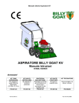
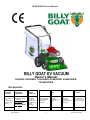
KVSP/TKVSP Owner’s Manual
Owner's Manual
KV600SP, KV650SPH, TKV650SPH, KV600SPFB, KV650SPHFB,
TKV650SPHFB
Accessories
ON BOARD
VACUUM
HOSE KIT
OPTIONAL
FELT/MESH
DEBRIS BAG
NOZZLE
WEAR
GUARD KIT
CASTER KIT
SHREDDER
KIT
KV LINER KIT
PROTECTIVE
COVER
4"(102mm) x
7.5' (2.13m)
For
vacuuming in
hard to reach
areas.
For use in leaves
and grass in dusty
conditions.
For use in
increasing
the life of
your nozzle
by protecting
it from
damage
To allow for
easy rolling and
maneuverability
on smooth
surfaces.
Shreds
leaves,
reducing total
volume.
Increases the
life of the
housing by
protecting it from
damage.
Protects the
machine from
the environment
when not in use.
P/N 891127
P/N 891128
P/N 891153
P/N 891134
P/N 891137
P/N 891126 FELT
BAG
P/N 891132 MESH
BAG,
P/N 891125
Part No 891204
1
Form No F071013B
KVSP/TKVSP Owner’s Manual
CONTENTS
SPECIFICATIONS AND SOUND/VIBRATION
3
INSTRUCTION LABELS
4
PACKING CHECKLIST & ASSEMBLY
5
ASSEMBLY
6
OPERATION
7-8
MAINTENANCE
TROUBLESHOOTING
_ 9-11
____________________________
ILLUSTRATED PARTS & PARTS LISTS
12
13-15
Go to http://www.billygoat.com for French-Canadian translations of the product manuals.
Visitez http://www.billygoat.com pour la version canadienne-française des manuels de produits
Part No 891204
2
Form No F071013B
KVSP/TKVSP Owner’s Manual
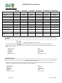
Specifications
KV600SP
Engine: HP
KV650SPH
TKV650SPH
KV600SPFB
KV650SPHFB TKV650SPHFB
6.0 (4.47kW)
6.5 (4.85kW)
6.5 (4.85 kW)
6.0 (4.47kW)
6.5 (4.85kW)
6.5 (4.85 kW)
Engine: Type
B&S Quantum
HONDA
HONDA
B&S Quantum
HONDA
HONDA
Engine: Model
112K020124E1
GSV190AN1L
GSV190AN1L
112K020124E1
GSV190AN1L
GSV190AN1L
Engine: Fuel Capacity
1.5 qt. (1.4 L)
1.6 qt. (1.5 L)
1.6 qt. (1.5 L)
1.5 qt. (1.4 L)
1.6 qt. (1.5 L)
1.6 qt. (1.5 L)
Engine: Oil Capacity
0.63 qt. (0.6 L)
0.58 qt (0.54L)
0.58 qt (0.54L)
0.63 qt. (0.6 L)
0.58 qt (0.54L)
0.58 qt (0.54L)
Total Unit Weight:
#129 (58.5 kg)
#132 (58.9 kg)
141# (64 kg)
#129 (58.5 kg)
#132 (58.9 kg)
141# (64 kg)
Overall Length
59” (1.5m)
59” (1.5m)
59” (1.5 m)
59” (1.5m)
59” (1.5m)
59” (1.5 m)
Overall Width
25.5” (.6 m)
25.5” (.6 m)
25.5” (.6 m)
25.5” (.6 m)
25.5” (.6 m)
25.5” (.6 m)
Overall Height
42.75” (1.1m)
42.75” (1.1m)
42.75” (1.1 m)
42.75” (1.1m)
42.75” (1.1m)
42.75” (1.1 m)
Max. operating slope
20
0
20
0
20
Sound in accordance with
2000/14/EEC standards
109 dBa
109 dBa
Sound at operator’s ear
88 dBa
89 dBa
Vibration at operator
position
0.71 g
2
(6.96m/s )
0
20
112 dBa
0.32 g (3.16m/s )
20
109 dBa
91 dBa
2
0
0.43 g (4.25m/s )
20
109 dBa
88 dBa
2
0
112 dBa
89 dBa
2
0.71 g (6.96m/s )
0
91 dBa
2
0.32 g (3.16m/s )
SOUND
SOUND LEVEL 92 dB(a) at Operator Position
Sound tests were conducted in accordance with 2000/14/EEC, and were performed on 7-25-07 under the conditions listed below.
Sound power level listed is the highest value for any model covered in this manual. Please refer to serial plate on the unit for the sound
power level for your model.
General Conditions:
Temperature:
Wind Speed:
Wind Direction:
Humidity:
Barometric Pressure:
Sunny
o
o
88 F (31.1 C)
2 mph (3.8 kmh)
South Southeast
44%
30.07”Hg (764 mm Hg)
VIBRATION DATA
2
VIBRATION LEVEL 0.34g (3.29m/s )
Vibration levels at the operator’s handles were measured in the vertical, lateral and longitudinal directions using calibrated vibration test
equipment. Tests were performed on 12-19-2007 under the conditions listed below.
General Conditions:
Temperature:
Wind Speed:
Wind Direction:
Humidity:
Barometric Pressure:
Part No 891204
Sunny
o
o
50 F (10 C)
4 mph (6.4kph)
South Southeast
68%
30 Hg (101.6kpa)
3
2
0.43 g (4.25m/s )
Form No F071013B
KVSP/TKVSP Owner’s Manual
INSTRUCTION LABELS
®
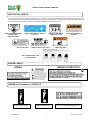
The labels shown below were installed on your BILLY GOAT KV Vacuum. If any labels are damaged or missing, replace them before operating
this equipment. Item numbers from the Illustrated Parts List and part numbers are provided for convenience in ordering replacement labels. The
correct position for each label may be determined by referring to the Figure and Item numbers shown.
LABEL DANGER KEEP HANDS
AND FEET AWAY
ITEM #18 P/N 400424
LABEL SAFETY PROTECT ITEM #20
P/N 100346
LABEL EXPLOSIVE FUEL
ITEM # 16 P/N 400268
DANGER FLYING DEBRIS
ITEM #19 P/N 810736
CHIPPER WARNING LABEL
ITEM #82 P/N 890152 (TKV ONLY)
LABEL SPARK ARRESTOR
P/N 100252
LABEL DANGER GUARD
ITEM #39 P/N 900327
BAG FOLDING INSTRUCTIONS
LOCATED ON BAG
ENGINE LABELS
HONDA
BRIGGS & STRATTON
Las Skotselinstruktionen Innan Start.
ENGINE and Transmission CONTROLS
Honda Throttle Control
Part No 891204
Briggs Throttle Control
4
Bail Drive Engage/Disengage label
Form No F071013B
KVSP/TKVSP Owner’s Manual
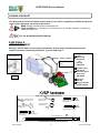
PACKING CHECKLIST
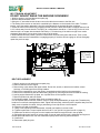
Your Billy Goat KV Vacuum is shipped from the factory in one carton, completely assembled except for the
upper handle, debris bag, and bag quick disconnect.
READ all safety instructions before assembling unit.
TAKE CAUTION when removing the unit from the box the Handle Assembly is attached by
cables and folded over
PUT OIL IN ENGINE BEFORE STARTING
PARTS BAG &
LITERATURE ASSY
Warranty card P/N- 400972, Owner’s Manual P/N-891204, General Safety and Warnings Manual P/N100294, Declaration of Conformity P/N-891057, Ty-wraps 900407 qty 2.
Quick disconnect
Use Ty-wraps
here
Boxing Parts
Checklist
Debris Bag
P/N-891132
OR
Felt Bag
P/N-891126
Literature Assy
P/N-891121
Connector Quick
Disconnect
P/N-890630
Fig. 2
Honda 6.5
GSV 190
Briggs & Stratton
6.0 HP Quantum
99
48
Washer 1/4 SAE
8172007 qty. 3
49
58
Nut Acorn High Crown
840071 qty. 2
Screwcap 1/4-20 X 2 " HCS ZP
8041010 qty. 1
Nut Lock 5/16-18
8160002 qty. 2
Washer 5/16 FLAT
8171003 qty. 4
50
51
Screwcap 5/16-18 X 1 3/4" GR 5
HCS ZP 8041031 qty. 2
57
Screwcap 1/4"-20 x 1 3/4" HCS ZP
8041009 qty. 1
98
Ty-wrap 900407 qty. 1
Part No 891204
5
Form No F071013B
KVSP/TKVSP Owner’s Manual
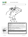
ASSEMBLY
1. ASSEMBLE the upper handle (item 11), with the hardware from the parts bag
(items 32, 33, and 34) to the lower handle (item 10). Tighten the hardware securely.
(See image above)
2. ATTACH the throttle lever (item 22) to the right side of the handle with the
hardware from the parts bag (items 58, 48, and 54). Secure the cable with the TyWrap (item 98).
3. ATTACH the Clutch cable (item 24) to the inner right side of the handle with the
hardware items 54, 48, and 57. Then attach the end of the cable to the bail. After it is
attached Check to make sure it is functioning properly.
4. UNFOLD the debris bag (item 21) and fasten bag neck to bag quick disconnect
(item 12). Attach firmly to housing exhaust (item 1) see fig. 2.
5. ATTACH bag to four posts (item 13), preassembled to upper handle.
6. CONNECT spark plug wire.
Insert the quick disconnect from the inside of the bag, tilt the handle so it can
be fed through first. Then slide the connecting end through and tighten the
strap
Part No 891204
6
Form No F071013B
KVSP/TKVSP Owner’s Manual
OPERATION
VACUUMING OPERATION
VACUUM NOZZLE HEIGHT ADJUSTMENT: Nozzle height is raised and lowered by rotating the red knob
near the left rear wheel. Nozzle height should be adjusted based on the task being performed.
FOR MAXIMUM PICKUP: Adjust nozzle close to debris, but without blocking airflow into the nozzle. NOTE:
Never bury nozzle into debris.
CLEARING A CLOGGED NOZZLE & EXHAUST: Turn engine off and wait for impeller to stop completely
and disconnect spark plug wire. Wearing durable gloves, remove clog. Danger, the clog may contain sharp
materials. Reconnect spark plug wire.
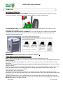
DEBRIS BAG
(OPTIONAL DEBRIS BAGS ARE AVAILABLE FOR CHANGING CONDITIONS)
Debris bags are normal replaceable wear items.
Note: Frequently empty debris to prevent bag overloading with more weight than you can lift.
An optional felt bag is available for use where debris will be vacuumed in dusty conditions (see Optional Accessories
shown on page 1).
DO NOT place bag on or near hot surface, such as engine. Be sure engine has come to a complete stop before removing or
emptying bag.
This vacuum is designed for picking up trash, organic material and other similar debris (see Safety and General
Operation manual).
However, many vacuums are used where dust is mixed with trash. Your unit can intermittently vacuum in dusty areas.
Dust is the greatest cause of lost vacuum performance. However, following these rules will help maintain your
machine's ability to vacuum in dusty conditions:
• Run machine at idle to quarter throttle.
• The debris bag must be cleaned more frequently. A vacuum with a clean, pillow soft bag will have good pickup
performance. One with a dirty, tight bag will have poor pickup performance. If dirty, empty debris and vigorously shake
bag free of dust.
• Pressure-wash debris bag if normal cleaning does not fully clean bag. Bag should be thoroughly dry before use.
NOTE: Having one or more spare debris bags is a good way to reduce down time while dirty bags are being cleaned.
DO NOT leave debris in bag while in storage.
Part No 891204
7
Form No F071013B
KVSP/TKVSP Owner’s Manual
COMPOST
Vacuumed leaves, grass and other organic material from your own yard can be emptied into a pile or composter to
provide enriched soil for later use as fertilizer in gardens and flower beds
NOTE: Allow green chips to dry before spreading around living plants.
MULCH
Wood chips made from branches in your own yard make excellent mulch. A thick blanket of wood chips around
plants and flowers to keeps weeds out and moisture in.
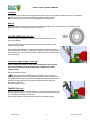
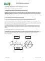
CHIPPER OPERATION (TKV only)
Your TKV chipper is designed to process tree branches and limbs up to 2"
(50.8mm) diameter.
Several small branches can be grouped together and fed together into the
chipper (see figure right).
When feeding forked branches, squeeze forks together and feed into chipper
entrance (DO NOT overload). If forks are too large, use a pair of loppers to trim
forks down to size. A lopper storage bracket is provided on every unit (loppers
are not included)
Clearing a clogged chipper (TKV only)
Under normal circumstances, allow time for machine to clear all wood
from chipper hopper before stopping engine. Otherwise, remaining
pieces of wood will jam inside of chipper when engine stops. (See
Tamper below).
Disconnect spark plug wire.
Remove debris bag quick disconnect from debris outlet on machine.
Wearing durable gloves, access impeller through debris outlet on fan housing
and rotate impeller counter clock wise to dislodge and remove jam and remove
debris from hopper with tongs or equivalent. Reconnect debris bag quick
disconnect to machine.
Reconnect spark plug wire.
TAMPER (TKV only)
Before turning machine off, use the Tamper to slowly push remaining pieces of
wood through the chipper. This can prevent any remaining wood from jamming
in the chipper when machine is turned off.
Do not leave tamper on the ground, store tamper in the chipper hopper.
Part No 891204
8
Form No F071013B
KVSP/TKVSP Owner’s Manual
MAINTENANCE
PERIODIC MAINTENANCE
Periodic maintenance should be performed at the following intervals:
Maintenance Operation
Every Use (daily)
Every 5 hrs (daily)
Every 25 Hours
Inspect for loose, worn or damaged parts.
Clean Debris bag
Check bag strap tightness
Engine (See Engine Manual)
Check for excessive vibration
IMPELLER REMOVAL
1. Wait for engine to cool and disconnect spark plug.
2. Drain fuel and oil from the engine.
3. Remove bag, quick release and upper handle. Do not kink, stretch, or break control cables, control
housings, or end fittings while removing handles.
4. Remove the transmission cover, idler pulley, transmission and the belt from the transmission.
5. Remove the transmission plate and the housing top plate by removing bolts around outside of housing.
6. Leaving engine fastened to top plate; turn it upside down so the impeller is on top.
7. Remove impeller bolt and lock washer.
8. Lift impeller upward. If impeller slides freely, proceed to (step 10).
9. If the impeller does not loosen, obtain a 3/4-16x3” (Billy Goat part #440192) or longer bolt. Thread bolt by
hand into nut until bolt rests against the shaft. Tighten the bolt slowly, which will pull the impeller away from the
shaft, remove impeller from shaft. Using a penetrating oil can help loosen a stuck impeller.
10. Using a new impeller bolt, lockwasher, and washer, reinstall new impeller in reverse order.
11. Tighten impeller bolt. Torque impeller bolt to 33-38 Ft. Lbs. (44-51 N.m) (see item 45 on page 15).
12. Reinstall engine onto housing in reverse order of removal make sure the belt is inside the two fingers on
the belt plate and that the belt is on the transmission pulley before securing the transmission.
13. Gas and oil.
14. Reconnect spark plug wire.
DRIVE CHAIN REPLACEMENT AND ALIGNMENT
1. Wait for engine to cool and disconnect spark plug.
2. To replace a chain, first prop up the rear of the machine with small blocks to get the rear wheels off of the
ground.
3. Remove the transmission cover, and the belt from the transmission.
4. Remove the bolts on both sides of the transmission holding the flange bearings; this should give enough
slack to slip the chain off.
4. Replace the old chain with a new one.
5. Once the chain is on, put the bolts back into the flange bearings and tighten.
6. Finally, make sure the wheels rotate freely. If not, loosen the bearings and shift them to get the chain
running straight up and down.
7. Reassemble the transmission components removed in steps 1-3 in reverse order.
Part No 891204
9
Form No F071013B
KVSP/TKVSP Owner’s Manual
BELT TENSION ADJUSTMENT
DO NOT ADJUST WHILE THE MACHINE IS RUNNING!
1. Wait for engine to cool and disconnect spark plug.
2. Remove the transmission cover
3. Using two ½” wrenches loosen the two nuts on the cable that connects to the idler arm.
4. The setting of the tension on the belt is controlled by the distance on the threads of the cable. To loosen
tension, move the position towards the end of the threads and in the opposite direction to tighten.
5. Check the travel of the idler arm by engaging the bail, which the drive should start to engage when the bail
is 2 ½ inches away from the handle. The spring, at a relaxed state should be 1.5 inches long on the coil, and
when the bail is in contact with the handle it should be 1.75 inches long. If the belt is too tight it can cause
premature failure and if it is too loose it can come off of the pulley.
6. When satisfied with the position, place the transmission cover back into place and secure. Then run the
machine to make sure the transmission is engaging properly. If the drive will not engage or will not disengage
repeat the previous steps.
Spring length
1.5”- resting
1.75”- bail at
handle
BELT REPLACEMENT
1. Wait for engine to cool and disconnect spark plug.
2. Drain fuel and oil from the engine.
3. Remove bag, quick release and upper handle. Do not kink, stretch, or break control cables, control
housings, or end fittings while removing handles.
4. Remove the transmission cover, idler pulley, transmission and the belt from the transmission.
5. Remove the transmission plate and the housing top plate by removing bolts around outside of housing.
6. Leaving engine fastened to top plate, turn it upside down so the impeller is on top.
7. Remove impeller bolt and lock washer.
8. Lift impeller upward. If impeller slides freely, proceed to (step 10).
9. If the impeller does not loosen, obtain a 3/4-16x3” (Billy Goat part #440192) or longer bolt. Thread bolt by
hand into nut until bolt rests against the shaft. Tighten the bolt slowly, which will pull the impeller away from the
shaft, remove impeller from shaft. Using a penetrating oil can help loosen a stuck impeller.
10. Place the new belt on the shaft.
11. Using a new impeller bolt and lockwasher, reinstall new impeller in reverse order.
12. Tighten impeller bolt. Torque impeller bolt to 33-40 Ft. Lbs. (44-54 N.m) (see item 45 on page 15).
13. Make sure the belt is in the groove on the impeller and feed it through the hole in the top plate.
14. Reinstall engine onto housing in reverse order of removal make sure the belt is inside the two fingers on
the belt plate and that the belt is on the transmission pulley before securing the transmission.
15. Gas and oil.
16. Reconnect spark plug wire.
Part No 891204
10
Form No F071013B
KVSP/TKVSP Owner’s Manual
CHIPPER BLADE REMOVAL AND SHARPENING (TKV ONLY)
Chipper blades are normal replaceable wear items.
DANGER Chipper blade is sharp. Replace any damaged blade.
Depending on the type and amount of wood being chipped, the chipper blade will eventually get dull, losing its
cutting ability. Evidence of a dull blade is a noticeably reduced chipping ability or a rough cut on end of branch.
Note: The chipper blade gap is factory set and should be checked each time impeller is removed from engine
crankshaft and reset if required. If reassembly requires a different quantity of shim washers, Billy Goat® shim
washer must be used.
1. Follow the steps 1-6 on the impeller removal instructions.
2. Using a 3/16" Allen wrench and 1/2" open end wrench, remove chipper blade from impeller.
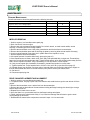
3. Sharpen blade by lightly grinding the cutting edge of the blade at 40 degrees (see figure below). It is not
necessary to remove all nicks from the cutting edge. CAUTION: Be careful to avoid heat buildup in the blade
during sharpening. This will reduce its heat- treated hardness properties and will reduce blade life. Evidence of
too much heat build-up is a change of color along sharpened edge.
4. The same chipper blade can be sharpened several times. However, blade replacement is required when
blade no longer overhangs the chip relief hole in impeller back plate or if increased vibration occurs (see fig
below).
5. Chipper blade installation is in reverse order of removal.
For Shim Washers- If gap is less than 0.040"(0.51mm), add shim washer 890130 (0.060"{1.52mm} thick)
and/or 890131(0.020" {1.02mm} thick), whichever is required. If gap is more than 0.080"(2.03mm), remove one
or more shim washers as needed to obtain correct gap. The chipper will function at up to a maximum of
0.125"(3.18mm) gap.
Correct
Incorrect
Blade
400
Edge of chip
relief hole
Part No 891204
11
Form No F071013B
KVSP/TKVSP Owner’s Manual
Troubleshooting
Problem
Abnormal vibration.
Will not vacuum or has poor
vacuum performance
Engine will not start.
Possible Cause
· Loose or out of balance impeller or
loose engine
· dirty debris bag. Hose kit cap missing.
·Clogged nozzle or exhaust. Excessive
quantity of debris.
· Improper nozzle height
Solution
· Check impeller and replace if required.
Check engine
· Clean debris bag. Shake bag clean or
wash. Check for hose kit cap. Unclog
nozzle or exhaust. Allow air to feed with
debris
· Adjust nozzle height so that it is closer
to the debris
· Throttle in off position. Engine not in full
choke position. Out of gasoline. Bad or
old gasoline. Sparkplug wire
disconnected. Dirty air cleaner
· Check stop switches, throttle, choke
position and gasoline. Connect spark
plug wire. Clean or replace air filter. Or
contact a qualified service person.
Engine is locked, will not pull · Debris locked in impeller. Engine
over.
problem.
Nozzle scrapes ground in
lowest height setting.
No self-propelling
Self propelled drive will not
release
Noisy or broken chain
Unit does not free-wheel
backwards
Too much dust coming from
bag.
Part No 891204
· See page 5. Contact a engine service
dealer for engine problems
Adjust nozzle height (See Nozzle height
Nozzle height out of adjustment
fine adjustment for hard surfaces on
page 5
· Drive bail not engaged
· Engage the drive bail.
· Drive belt worn or broken
· Check the drive belt.
· Drive clutch cable out of adjustment or · Check the drive clutch cable (see page
broken.
12).
· Drive chain off the sprocket.
· Check the drive chain (see page 12).
· Improper drive clutch cable adjustment · Check the drive clutch cable (see page
or cable is kinked.
13).
· No chain lubrication.
· Lubricate chain.
· Chain misalignment or tension.
· Check the drive chain (see page 12).
· None
· Push the unit slightly forward then the
unit will free-wheel
· Vacuuming very dry, brittle or small
· Switch to felt bag (see page 1
debris
accessories)
12
Form No F071013B
KVSP/TKVSP Owner’s Manual
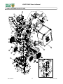
PARTS DRAWING KVSP/TKVSP
Part No 891204
13
Form No F071013B
KVSP/TKVSP Owner’s Manual
PARTS LIST KVSP/TKVSP
ITEM
NO.
1
2
3
4
5
6
7
8
9
MAIN FRAME HOUSING KV
NOZZLE ASSEMBLY TKV
AXLE WA KV MICRO
PLATE TOP WA KVSP
IMPELLER SERRATED 14.25 WA KVSP
DOOR EXHAUST ASSY RAW
WASHER 1/2" SAE Z/P
WHEEL ASSY 12" X 2.5" TREAD
ENGINE 6.5 HP HONDA GSV190AN1L
ENGINE 6 BRIGGSAND STRATTON
LOWER HANDLE KV
HANDLE UPPER KVSP
QUICK DISCONNECT
PIN CLEVIS 3/8" x 2.125" LONG
RETAINER
GRIP HANDLE 1"X 9.5" LG
LABEL HOT ENGINE EN/SP
KV600SP/KV600SPFB
PART NUMBER
891100-S
891110-S
891138
891101-S
891104-S
890148-01
8172011
900509
890622
891050
891054-S
890630
520120
360279
430342
100261
LABEL WARNING DANGER
LABEL DANGER FLYING DEBRIS
LABEL SAFETY PROTECT READ MANUAL
BAG DEBRIS NO ZIPPER KV
BAG FELT W/SKIRT KV (FB MODELS)
CABLE THROTTLE ASSY 42" W/CHOKE
23
24
25
26
27
28
29
30
31
32
33
34
35
36
37
38
39
40
41
42
43
44
45
SCREW CAP 3/8-24 x 3 1/2 GR. 8 W /PATCH
10
11
12
13
14
15
16
17
18
19
20
21
22
1
1
1
1
1
1
5
2
1
1
1
1
4
4
2
1
KV650SPH/KV650SPHFB
PART NUMBER
891100-S
891110-S
891138
891101-S
891104-S
890148-01
8172011
900509
840069
891050
891054-S
890630
520120
360279
430342
-
400424
810736
100346
891132
891211
891036
2
1
1
1
1
1
J BOLT 3/8-16 X 6"
891071
CABLE CLUTCH DRIVE ASSY 40" KVSP
LABEL CLUTCH VQ
BRACKET TRANS MOUNT WA KV
ARM IDLER DRIVE WA KV
TRANS SINGLE SPEED W/DIFF
SPROCKET 8 TOOTH #43 OR #65
CHAIN #43 X 58 PITCHES
GUARD DRIVE KV
BEARING 1/2" PRESSED STEEL HOUSING
BRACKET TRANS FIX KV
PLATE CHAIN REINFORCE KV
PULLEY IDLER 2" OD X 3/8" ID
SPRING TENSION
BAIL CLUTCH WA KVSP
BRACKET IDLER BELT FINGER KV
LABEL DANGER GUARD
WHEEL ASSY SP 26T SPROCKET
SPACER 1.50OD X .890ID X .5 THK
WASHER LOCK 3/8 ST MED
SQ KEY 2.125 X .187
NUT LOCK 3/8-16 THIN
891032
900328
891106
891105
891020
891022
891023
891004-S
891025
891012
891014
840087
800242
891102
891028
900327
890242
8177012
9201087
8161042
440151
Description
Part No 891204
14
1
1
1
1
1
1
5
2
1
1
1
1
4
4
2
-
TKV650SPH/TKV650SPHFB
PART NUMBER
891100-S
891110-S
891138
891107-S
891109-S
890148-01
8172011
900509
840069
891050
891054-S
890630
520120
360279
430342
-
400424
810736
100346
891132
891211
891027
2
1
1
1
1
1
400424
810736
100346
891132
891211
891027
2
1
1
1
1
1
1
891071
1
891071
1
1
1
1
1
1
2
2
1
2
1
2
1
1
1
1
1
2
1
1
1
891032
900328
891106
891105
891020
891022
891023
891004-S
891025
891012
891014
840087
800242
891102
891028
900327
890242
840083
8177012
9201087
8161042
1
1
1
1
1
2
2
1
2
1
2
1
1
1
1
1
2
1
1
1
1
891032
900328
891106
891105
891020
891022
891023
891004-S
891025
891012
891014
840087
800242
891102
891028
900327
890242
840083
8177012
9201087
8161042
1
1
1
1
1
2
2
1
2
1
2
1
1
1
1
1
2
1
1
1
1
1
440151
1
440151
1
QTY
QTY
Form No F071013B
QTY
1
1
1
1
1
1
5
2
1
1
1
1
4
4
2
-
KVSP/TKVSP Owner’s Manual
KV600SP/KV600SPFB
KV650SPH/KV650SPHFB
TKV650SPH/TKV650SPHFB
QTY
QTY
QTY
PART NUMBER
PART NUMBER
PART NUMBER
46
47
48
49
50
51
52
53
54
55
56
57
58
59
60
61
62
63
64
65
66
67
68
69
70
71
72
73
74
75
76
77
78
79
80
81
82
83
84
85
86
87
88
89
91
92
93
94
95
96
97
98
99
SCREWCAP 1/4 - 20 x 5/8 HWH
BOLT IDLER 3/8-16 X 1 1/2
WASHER 1/4" SAE ZP
WASHER 5/16 FLATWASHER Z/P
SCREWCAP 5/16-18 X 1.75 ZP
NUT LOCK 5/16-18
NYLON INSERT LOCKNUT, 3/8-16 UNC
SCREWCAP 1/4-20 X 3/4"
NYLON INSERT LOCKNUT, 1/4-20 UNC
SCREWCAP #10-14 X 3/4" HWH ZP
1/2-13 CAP NUT NP W/PATCH
SCREWCAP 1/4-20 x 1 3/4 HCS ZP
SCREWCAP 1/4-20x2"
BELT 3V315
BEARING BALL FLANGED
NOZZLE TOP HALF KV
NOZZLE BOTTOM HALF KV
PLUG HOUSING KD LB
SCREW PLASTIC 1/4-20 X 1
WASHER 1.5 OD X .453 ID X .25 THK
890359
800888
8172007
8171003
8041031
8160002
8160003
8041004
8160001
891043
890530
8041009
8041010
891026
900774
891002
891003
900146-01
891039
440153
26
1
17
19
8
8
2
2
12
3
4
1
1
1
4
1
1
1
8
1
890359
800888
8172007
8171003
8041031
8160002
8160003
8041004
8160001
891043
890530
8041009
8041010
891026
900774
891002
891003
900146-01
891039
440153
26
1
17
19
8
8
2
2
12
3
4
1
1
1
4
1
1
1
8
1
890359
800888
8172007
8171003
8041031
8160002
8160003
8041004
8160001
891043
890530
8041009
8041010
891026
900774
891002
891003
900146-01
891039
440153
24
1
17
19
8
8
2
2
15
3
4
1
1
1
4
1
1
1
8
1
SPROCKET 65A26 26 TOOTH
890238
2
890238
2
890238
2
SCREW SELF TAP 1/4 x 0.75
SCREW PLASTITE 1/4-20 X 3/4 HWH ZP
SCREWCAP #10-24 X 5/8"
NYLON INSERT LOCKNUT 10-32 UNF ZINC
SCREW SOCKET HD 5/16-18 X 3/4 GR. 8
NUT KEPS 5/16-18
WASHER SHIM 0.875 ID X 0.060
WASHER SHIM 0.875 ID X 0.020
BLADE CHIPPER KD501
GUARD FLAPPER
PLATE FLAPPER ENTRANCE
LABEL SPARK ARRESTOR EN/SP
TAMPER CHIPPER
LABEL DANGER CHIPPER
CLIP 1/2"
WOODRUFF KEY 1/8 X 1/2
WASHER 1/2" FC
SPRING COMPRESSION
LABEL DECAL KV/TKV
SCREW SM 1/4 X 3/4 DRILL PT
WASHER 1/4" SAE BLACK OXIDE
900505
840082
350146
510180
8171006
891072
891046
510208
510193
10
3
4
2
2
1
1
4
4
900505
840082
100252
350146
510180
8171006
891072
891046
510208
510193
10
3
1
4
2
2
1
1
4
4
900505
840082
8059135
8164005
890103
890104
891065
891041
890101
890119
890127
100252
890229
890152
350146
510180
8171006
891072
891047
510208
510193
10
3
4
4
2
2
2
0-3
1
2
2
1
1
1
4
2
2
1
1
4
4
CARRIAGE BOLT 1/4"-20 X 3/4"
SCREWCAP 1/4-20 X 1" HCS ZP
KV NOZZLE BRACKET
8024021
8041006
891208
4
6
2
8024021
8041006
891208
4
6
2
8024021
8041006
891208
4
6
2
KNOB 3/8-16 RED
SPRING LEVER GZ
TY WRAP
NUT 1/4-20 ACORN
891070
610429
900407
840071
1
1
4
2
891070
610429
900407
840071
1
1
4
2
891070
610429
900407
840071
1
1
4
2
105
LABEL MADE IN U.S.A.
520116
1
520116
1
520116
1
106
107
GROMMET FLANGE 1/2" MOLDED
830176
1
830176
1
830176
1
SPRING COMPRESSION
400332
1
400332
1
400332
1
100
Part No 891204
15
Form No F071013B