1
INSTALLATION
INSTRUCTIONS
DOUBLE O-RING
GEOTHERMAL
FLOW CENTERS
Models: DORFC-1DORFC-2
DORFC-1
DORFC-2
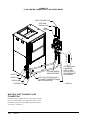
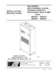
WARNING: After flushing is complete, but prior to pump motor start-up, loosen the large screw in
the center of the pump motor(s) to allow air to escape. Once water has seeped out around the screw,
re-tighten. Failure to perform this step will likely result in premature pump motor failure!
PUMP MOTOR REPLACEMENT: Bard Part #8300-003 (UP26-99F)
BMC, Inc.
Bryan, Ohio 43506
Manual:2100-518B
Supersedes:2100-518A
File:
Volume I, Tab 8
Date:04-23-12
Manual2100-518B
Page
1 of 30
Contents
Getting Other Informations and Publications.......... 3
General Information
Flow Center Nomenclature........................................ 4
Application
Description................................................................. 4
Safety
.................................................................. 4
Danger .................................................................. 4
Warning .................................................................. 4
Caution .................................................................. 4
Notice
.................................................................. 4
Flow Center Mounting Instructions
Notice
.................................................................. 7
Stud Wall .................................................................. 7
Concrete/Masonry Wall.............................................. 7
Side of Unit................................................................ 7
Piping Installation
Description............................................................... 10
Actual Photo Images........................................... 10-11
Multiple Unit to Single Loop Connection
Description............................................................... 12
Figures
Figure 1A Performance Model DORFC-1.................. 5
Figure 1B Performance Model DORFC-2.................. 5
Figure 2 Flow Center Dimensions........................... 6
Figure 3 Pump Horizontal Applications................... 8
Figure 4AMounting - Studded Wall........................... 9
Figure 4BMounting - Masonry Wall........................... 9
Figure 5AFlow Center Connection to GV Series.... 12
Figure 5BFlow Center Connection to GT Series.... 13
Figure 5CFlow Center Connection to QW Series... 14
Figure 6 Multiple Unit Connection to Singular....... 15
Figure 7 Electrical Connections............................. 17
Figure 8 Connecting Flush Cart to Flow Center.... 19
Figure 9APositioning - Flush Loop.......................... 20
Figure 9BPositioning - Flush Loop & Unit............... 20
Figure 9CPositioning - Flush Unit........................... 21
Figure 9DPositioning - Operation............................ 21
Figure 10 Pressure Temperature Ports................... 25
Figure 11 Density Verification - Solution Strength..... 30
Manual2100-518B
Page
2 of 30
Flow Center Wiring
Description............................................................... 16
Flushing & Charging
General ................................................................ 18
Procedures for Adding Antifreeze............................ 18
Flushing & Filling Earth Loop & Units...................... 22
Flushing Earth Loop Only........................................ 22
Flushing Unit Only.................................................... 23
Flow Center Initial Startup
General ................................................................ 24
Procedures for Pressurizing the System.................. 24
Pressure/Temperature Plugs................................... 24
Troubleshooting
Troubleshooting Table.............................................. 27
Antifreeze Selection & Use
General ................................................................ 28
Methanol ................................................................ 28
Ethanol ................................................................ 28
Propylene Glycol...................................................... 29
Potassium Acetate (GS4)......................................... 29
Antifreeze Verification.............................................. 30
Tables
Table 1 Fusion or Barbed Fittings........................ 10
Table 2 Electrical Ratings.................................... 16
Table 3A GV Series Coil Pressure Drop................ 25
Table 3B GT Series Coil Pressure Drop................. 26
Table 3C QW Series Coil Pressure Drop............... 26
TableTroubleshooting...................................... 27
Table 4 Fluid Volume........................................... 29
Table 5 Percentages by Volume.......................... 29
Table 6 Propylene Glycol Specific Gravity........... 30
Table 7 Methanol Specific Gravity....................... 30
Getting Other Information and Publications
These publications can help you install the air
conditioner or heat pump. You can usually find these
at your local library or purchase them directly from the
publisher. Be sure to consult current edition of each
standard.
National Electrical Code........................ANSI/NFPA 70
Standard for the Installation................ ANSI/NFPA 90A
of Air Conditioning and Ventilating Systems
Standard for Warm Air........................ ANSI/NFPA 90B
Heating and Air Conditioning Systems
Load Calculation for Residential ....... ACCA Manual J
Winter and Summer Air Conditioning
Duct Design for Residential...............ACCA Manual D
Winter and Summer Air Conditioning and Equipment
Selection
Closed-Loop/Ground Source Heat Pump.........IGSHPA
Systems Installation Guide
Grouting Procedures for Ground-Source..........IGSHPA
Heat Pump Systems
Soil and Rock Classification for.......................IGSHPA
the Design of Ground-Coupled Heat Pump Systems
Ground Source Installation Standards..............IGSHPA
Closed-Loop Geothermal Systems...................IGSHPA
– Slinky Installation Guide
For more information, contact
these publishers:
ACCA
Air Conditioning Contractors of America
1712 New Hampshire Avenue
Washington, DC 20009
Telephone: (202) 483-9370
Fax: (202) 234-4721
ANSI
American National Standards Institute
11 West Street, 13th Floor
New York, NY 10036
Telephone: (212) 642-4900
Fax: (212) 302-1286
ASHRAE American Society of Heating Refrigerating, and Air Conditioning Engineers, Inc.
1791 Tullie Circle, N.E.
Atlanta, GA 30329-2305
Telephone: (404) 636-8400
Fax: (404) 321-5478
NFPA
National Fire Protection Association
Batterymarch Park
P.O. Box 9101
Quincy, MA 02269-9901
Telephone: (800) 344-3555
Fax: (617) 984-7057
IGSHPA
International Ground Source
Heat Pump Association
490 Cordell South
Stillwater, OK 74078-8018
Manual2100-518B
Page
3 of 30
geothermal flow centers nOMENCLATURE
DORFC
2
Double
O-Ring
Flow
Center
1 = 1-Pump Version, 208/230V, 60 Hz, 1-phase, 22’ HD @ 16 GPM
2 = 2-Pump Version, 208/230V, 60 Hz, 1-phase, 44’ HD @ 16 GPM
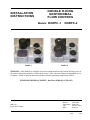
fLow center description
warning
The DORFC Series Flow Centers are a compact, easy to
mount polystyrene cabinet that contains 3-way valves and
pump(s) with connections for flushing, filling and pumping
fluids for geothermal closed loop systems. The proven
design is foam insulated to prevent condensation and full
flow service valves minimize pressure drop.
Indicates a potentially hazardous situation which, if not
avoided, will result in death or serious injury.
One or two Grundfos pump models UP26-99 are available
based upon flow requirements and loop design.
Unit and loop connections are designed for double o-ring
fittings with several varieties of connections available
(fusion, threaded, barbed and sweat). Pump motor(s) are
230VAC, 60 Hz, 1-phase.
An attractive light gray polystyrene cabinet (that matches
geothermal unit) with black pump(s) provides an
aesthetically pleasing enclosure for pump(s) and valves.
SAfEty
Warnings, cautions and notices appear throughout this
Manual. Read these items carefully before attempting any
installation, service or troubleshooting of the equipment.
danger
Indicates an immediate hazardous situation which, if not
avoided, will result in death or serious injury. DANGER
labels on unit access panels must be observed.
Manual2100-518B
Page 4 of 30
caution
Indicates a potentially hazardous situation or an unsafe
practice which, if not avoided, could result in minor or
moderate injury or product or property damage.
notice
Notification of installation, operation or maintenance
information, which is important, but which is not hazardrelated.
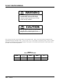
WARNING
Failure to do so could cause property
damage, bodily harm or death.
caution
Failure to do so could cause property
damage, bodily harm or death.
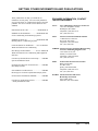
FLOW CENTER PERFORMANCE
flow center performance
FIGURE 1A
PERFORMANCE MODEL DORFC-1 FLOW CENTER
35
30
20
15
10
5
0
0
5
10
15
20
25
30
35
Flow (GPM)
FIGURE 1B
PERFORMANCE MODEL DORFC-2 FLOW CENTER
70
60
50
Head (Feet)
Head (Feet)
25
40
30
20
10
0
0
5
10
15
20
25
30
35
Flow (GPM)
Manual 2100-518A
Page
5 of 30
Manual2100-518B
Page
5 of 30
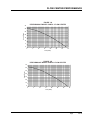
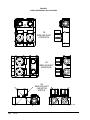
dimensional drawing
figure 2
flow center dimensions
F
G
A
D
H
C
INCHES
CM
A
13.5
34.3
B
B
10.3
26.2
C
7.5
19.1
D
12.4
31.5
E
2.0
5.1
F
2.6
6.7
G
5.0
12.7
H
4.7
11.4
TYPE
DORFC-1
DORFC-2
SHIPPING WEIGHT
26 LBS
31 LBS
MIS-2658
Manual2100-518B
Page 6 of 30
flow center mounting
caution
The following instructions represent
industry accepted installation practices for
closed-loop earth coupled (ground loop)
installations. Instructions are provided to
assist the contractor in installing trouble
free ground loops. These instructions are
recommendations only. State/provincial and
local codes MUST be followed and installation
MUST conform to ALL applicable codes. It is
the responsibility of the installing contractor
to determine and comply with ALL applicable
codes and regulations.
notice
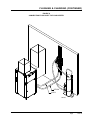
Side of unit
The Flow Center must be mounted with the pump shaft in
the horizontal position. In other words, it should always be
mounted in a vertical position (not on its back or mounted to
the ceiling). See Figure 3.
Mounting on the side of the unit is possible, but
not necessarily recommended because it can inhibit
serviceability and also lead to vibration of the sheet
metal casing. It could also lead to puncturing an internal
refrigerant or water pipe. If necessary, however, the flow
center can be mounted to the sheet metal casing utilizing
four (4) self-drilling screws. (Pay close attention not to
puncture internal components.)
The pump should be located as close to the unit as possible
to limit the length of rubber hose kit or interconnect piping
and thus its associated pressure drop.
Stud wall
Mounting on stud wall with or without drywall can be
accomplished by using two (2) lag bolts through the top and
bottom center holes directly into the stud. See Figure 4A.
concrete/masonry wall
Mounting onto a concrete wall can be accomplished
typically using four (4) 1/4" diameter tapcon cement screws
in the four (4) outer corner mounting holes. See Figure 4B.
Manual2100-518B
Page
7 of 30
figure 3
pump horizontal applications
OK
IMPELLER SHAFT
HORIZONTAL
OK
IMPELLER SHAFT
HORIZONTAL
NO
IMPELLER SHAFT
CAN NOT BE
VERTICAL
MIS-2659
Manual2100-518B
Page 8 of 30
figure 4
mounting
FIGURE 4A
Studded Wall Mounting
1/4" LAG BOLTS
DIRECTLY INTO STUD
FIGURE 4B
Masonry Wall Mounting
1/4" TAPCON SCREWS
MIS-2660
Manual2100-518B
Page
9 of 30
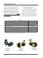
piping installation
The Flow Center features Double O-Ring fittings for
installation flexibility and ease of installation – maintaining
a reliable connection. Table 1 illustrates the connection
options available for Flow Centers. Pressure drop in
piping systems should be calculated to ensure adequate
flow through the unit. All piping should be properly
insulated with closed cell insulation of 1/2" wall thickness.
Piping insulation should be glued and sealed to prevent
condensation using closed cell insulation glue. The swivel
connectors on the flow center and at the unit are designed
to be hand-tightened only.
NOTE: Apply petroleum jelly to O-Rings to prevent damage and aid in insertion.
Loop side piping is typically polyethylene piping directly into
the flow center. Connection to the flow center can be made
with either a fusion or barbed fitting as shown in Table 1.
Connection between the flow center and the geothermal
heat pump typically would be made using the hose kit
(DORLFCK-1), which contains all fittings necessary for
connection between the heat pump and the flow center as
shown in Figure 5. Other variety of materials may also be
used for this connection - such as PE or copper piping.
TABLE 1
Description
Part Number
1-1/4" PE Fusion X Double O-Ring
DORF125-S
Double O-Ring Loop Flow Center Kit
DORLFCK-1
1" Barb X Double O-Ring (includes {4} hose clamps)
DORB1-S-4HC
1" MPT X Double O-Ring
DORMP1-S
1" FPT X Double O-Ring
DORFP1-S
1" Copper Sweat X Double O-Ring (includes {2} P/T fittings)
1" Hose Barb X Double O-Ring 90° Elbow (includes {4} hose clamps and {2} P/T fittings)
DORS1-S
DORB1-90-4HC
1" MPT X Double O-Ring, 90° Elbow (includes {2} P/T fittings)
DORMP1-90
Quick Connect Cam Lock X Double O-Ring 90° Elbow
DORCL1-90
Male Garden Hose Thread X Double O-Ring (1-piece per box)
DORGHMT
NOTE:All fittings boxed in pairs (2-pieces each) will exception of DORGHMT.
1-1/4" Socket Fusion X
Double O-ring
1" Hose Barb X
Double O-ring
DORF125-S
DORB1-S-4HC
Manual2100-518B
Page 10 of 30
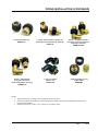
1" MPT X Double O-ring
DORMP1-S
piping installation (Continued)
1" Swivel X Double O-ring
DORFP1-S
Elbow, 1" MPT X Double
O-ring with 1/4" Port and
Pressure/Temperature Test Plugs
DORMP1-90
1" Copper Sweat X Double O-ring with 1/4"
FPT Port & Pressure/Temperature Test Plugs
DORS1-S
Elbow, 1" Hose Barb X Double
O-ring with 1/4" Port and Pressure/
Temperature Test Plugs
DORB1-90-4HC
1" Cam Lever Male X
Double O-ring
Garden Hose Male X O-ring
(single) Adapter
DORCL1-90
DORGHMT
NOTES:
1.
2.
3.
Apply petroleum jelly to O-Rings to prevent damage and aid in insertion.
Use two (2) stainless steel clamps per connection (included quantities of hose clamps with fittings and hose kits are per this recommendation).
Adaptors required from 1" MPT, 1" FPT, Copper, etc. provided by others.
Manual2100-518B
Page
11 of 30
figure 5A
flow center connection to GV Series model
PIPE TO GROUND LOOP
PIPE FROM
GROUND LOOP
PUMP
MODULE
STRAIGHT BARBED
BRASS ADAPTERS
WATER IN
WATER OUT
HOSE CLAMPS
NOTE: APPLY PETROLEUM JELLY
TO O-RINGS TO PREVENT DAMAGE
AND AID IN INSERTION.
1" FLEXIBLE HOSE
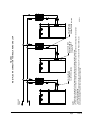
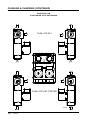
multiple unit to single loop
connection
In instances where multiple units are connected to a singular
loop, our recommendation is to apply a flow center to each
individual system with full-port balancing valves installed
on each unit. See Figure 6.
Manual2100-518B
Page 12 of 30
OPTIONAL VISUAL
FLOW METER
NOTE: IF USED
SUPPORT WITH A
FIELD-FABRICATED
WALL BRACKET
MIS-2621 A
figure 5B
flow center connection to GT Series model
PIPE FROM
GOUND LOOP
PIPE TO
GROUND LOOP
PUMP MODULE
STRAIGHT BARBED
BRASS ADAPTERS
OPTIONAL VISUAL
FLOW METER
NOTE: IF USED SUPPORT
WITH A FIELD FABRICATED
WALL BRACKET
HOSE CLAMPS
1" FLEXIBLE HOSE
NOTE: APPLY PETROLEUM JELLY
TO O-RINGS TO PREVENT DAMAGE
AND AID IN INSERTION
WATER OUT
WATER IN
MIS-2827 A
Manual2100-518B
Page
13 of 30
figure 5C
flow center connection to QW Series model
FLEXIBLE HOSE
PUMP MODULE
(See Spec Sheet
for Model No.)
PIPE FROM
GROUND LOOP
PIPE TO
GROUND
LOOP
NOTE: Apply petroleum
jelly to o-rings to prevent
damage and aid in insertion
WATER
OUT
MIS-2748 A
Manual2100-518B
Page 14 of 30
Manual2100-518B
Page
15 of 30
FIELD SUPPLIED
FULL PORT BALL
VALVE FOR BALANCING
EACH HEAT PUMP
FIELD SUPPLIED
MUST INCLUDE P/T
CHECK VALVE TO
PORTS TO VERIFY
PREVENT SHORT CYCLING
FLOW RATES
NOTES:
1. Piping is shown schematically. Actual pipe diameter and layout must be determined before installation.
2. Pressure drop calculation must be made to verify that parallel pumping arrangement provides enough head to deliver design flow rate to each unit
when all units are operating.
3. Flow controller should be mounted close enough to unit to maintain short (aprox. 10 ft., 3m) hose kit from Flow Controller to unit.
MIS-2664
4. All units must include P/T ports for flow rate measure and balancing.
GROUND
LOOP
figure 6
multiple unit connection to singular ground loop
flow center wiring
WARNING
To avoid possible injury or death due to
electrical shock, open the power supply
disconnect switch and secure it in an open
position during installation.
caution
Use only copper conductors for field installed
electrical wiring. Unit terminals are not
designed to accept other types of conductors.
Power wiring to the Flow Center should conform to all applicable codes. Figure 7 shows the required wiring between the
geothermal heat pump and the flow center. Note: the flow center is only available in 208/230 Volt, 60 Hz, 1-phase. The flow
center electrical connection interior of the heat pump control panel is circuit breaker protected (both L1 and L2 power lines).
See Table 2 for the electrical requirements.
TABLE 2
electrical ratings
Manual2100-518B
Page 16 of 30
Model
Pump
Quantity
Volts
Amps
HP
DORFC-1
1
230
1.07
1/6
DORFC-2
2
230
2.14
1/3
figure 7
electrical connections
FLOW CENTER
ELECTRICAL
ENTRANCE
FLOW CENTER
CONNECTION
L1
L2
38
Red
37
Black
Circuit Breakers
PUSH
3
MIS-2665
PUSH
3
Terminal Block 2
Manual2100-518B
Page
17 of 30
flushing & charging
All Flushing of earth loops should be performed using a
1.5 HP or larger pump (as specified by IGSHPA). Flushing
can be accomplished using three different methods. The
first flushing method applies a one-step installation of the
loop, unit and inside piping. The second method allows a
Loop Contractor to use flush cart when installing the loop,
and at a later date, the dealer can install the unit to the
loop using only domestic water to flush the unit. The third
procedure shown is used when replacing the pump, coaxial
refrigerant to water coil, or unit. The following are step-bystep procedures. Be careful not to rotate the 3-way valves
into a position where air can be introduced into the loop.
Reflushing will be required if this occurs. Valve position
can be verified by looking on the end of the valve stem for
the pattern position.
Consult the IGSHPA for more complete flushing and
antifreeze instructions.
Flush in one direction for one hour, deadheading
in increments - checking site glass for air pockets.
Reverse flow in opposite direction, again for one hour,
deadheading in increments - checking site glass for air
pockets.
The presence of air can be detected by “deadheading” the
pump. To deadhead the pump, close off the return to the
pump and watch the water level site glass. Once you have
no more than 1/2" to 3/4" drop in the site glass, you will
have achieved complete air removal.
Power flushing can be achieved using the home’s city water
supply (or well water) connected to the flush cart. This
uses the combined pressure of the flush cart pump and the
home’s water system for faster flushing.
Manual2100-518B
Page 18 of 30
After flushing is complete, but prior to unit start up,
remove the large screw from the center of the flow center
pump(s) to allow air to escape (water will drip out).
Replace the screw after pump has filled with fluid.
For final pressurization, run the unit in heating or cooling
for a period of 20 minutes. Following this 20 minute run
time, pressurize the loop using the flush cart to 50-75 psig in
winter or 40-50 psig in summer.
In areas where entering loop temperatures drop below
40°F (5°C) or where piping will be routed through areas
subject to freezing, antifreeze is needed to prevent the loop
from freezing inside the pipe or heat exchanger. Alcohols
and glycols are commonly used as antifreeze, however,
you should consult with your distributor for assistance in
selecting the antifreeze best suited for your region.
Procedures for adding
antifreeze
1. Flush cart should be half full of water.
2. Add measured amount of antifreeze through hose below the water level (calculate based upon loop).
3. Add antifreeze to loop side only (see valve position in Figure 9A).
4. Pump and dump (discharge).
5. Turn off pump; close discharge valve.
6. Repeat the procedure to add remaining antifreeze to loop.
flushing & charging (Continued)
figure 8
connecting flush cart to flow center
RETURN
SUPPLY
MIS-2661
Manual2100-518B
Page
19 of 30
flushing & charging (Continued)
figures 9A & 9B
flow center valve positioning
FLUSH LOOP ONLY
FLUSH LOOP & UNIT TOGETHER
MIS-2662
Manual2100-518B
Page 20 of 30
flushing & charging (Continued)
figures 9C & 9D
flow center valve positioning
FLUSH UNIT ONLY
OPERATION
MIS-2663
Manual2100-518B
Page
21 of 30
flushing & charging (continued)
flushing & filling earth loop and
unit(s) together
flushing earth loop only
All air and debris must be removed from the earth loop
piping system before operation. Flush the loop with a high
volume of water at a high velocity (2 fps in all piping in
accordance with IGSHPA guidelines).
2. Connect the unit side connections of the flow center together with a jumper hose.
1. Connect the unit and loop to the flow center.
2. Connect the flush cart hoses to the front port of the flow center (see Figure 8).
3. Fill closed loop (outside) evenly with domestic water and discharge the return water by adding water to the flush cart until water returns to the reservoir. The return water should be filtered or discharged to remove debris.
4. Fill the flush cart two-thirds full for initial flushing.
5. Flush the lowest portion of the system first. Depending upon the individual layout, this could be the loop or the unit. (If unit is lowest part of system, set valve position as shown in Figure 9C. If loop is lowest part of system, set flow center valve position as shown in Figure 9A.)
6. Restart the pump. Once you have a steady flow of water on the return side from the system, deadhead the pump by closing the ball valve on the hose returning to the reservoir. This will generate the maximum pressure on the system. While the return ball valve is closed, note the fluid level in the reservoir. If all the air is purged from the system, the level will drop only 1/2" to 3/4" in the flush cart site glass, since water is not compressible. This is the only way to tell if the air is purged from the system. Open valve quickly, wait one minute, then deadhead again. Repeat this process until all air is purged from the system.
7. Reverse the flow direction with the flush cart and repeat Step #6.
8. Repeat Step #6 for the higher elevation side of the system. (If unit is highest part of system, set valve position as shown Figure 9C. If loop is highest part of system, set flow center valve position as shown in Figure 9A.)
9. After flushing both sides of the system, reset flow control valves to flush the entire system. Set valve position as shown in Figure 9B and repeat Step #7.
Manual2100-518B
Page 22 of 30
1. Connect loop to flow center.
3. Remove caps and plugs from flow center front access ports.
4. Connect flush cart hoses to access ports.
5. Position valve stems as shown in Figure 9A.
6. Fill the flush cart two-thirds full for initial flushing.
7. Restart the pump. Once you have a steady flow of water on the return side from the system, deadhead the pump by closing the ball valve on the hose returning to the reservoir. This will generate the maximum pressure on the system. While the return ball valve is closed, note the fluid level in the reservoir. If all the air is purged from the system, the level will drop only 1/2" to 3/4" in the flush cart site glass, since water is not compressible. This is the only way to tell if the air is purged from the system. Open valve quickly, wait one minute, then deadhead again. Repeat this process until all air is purged from the system.
8. Reverse the flow direction with the flush cart and repeat Step #7.
9. Rotate the flow center valves to isolate the flush cart from the rest of the system (see Figure 9C).
10. Turn off flush cart pump, relieve pressure on the hoses and remove them.
11. Replace flow center access plugs and caps.
12. Rotate valves back to position as shown in Figure 9B.
13. Remove jumper from unit connection ports.
flushing & charging (continued)
flushing unit only (Also used
when replacing unit, coaxial
coil, hose kit or pump)
1. Connect unit to flow center.
2. Rotate 3-way valve to position shown in Figure 9C.
3. Remove access port caps and plugs and connect either flush cart or Bard DORGHMT fitting (service only - not intended for primary flush).
4. Attach garden hose to domestic water supply.
5. Purge air from garden hose before connecting to port in flow center.
6. Attach another length of garden hose to the other port in the flow center, leading to drain.
7. Flush flow center and unit with domestic water until air is removed.
8. Close drain valve on discharge hose and pressurize system to domestic water pressure (approx. 4-75 psig).
9. Remove bleed screw(s) from flow center pump motors to purge air and replace screw(s).
10. Close valve on supply hose to trap pressure in the system.
11. Rotate 3-way valves back to normal operating position (see Figure 9D).
12. Remove water supply hose from flow center and replace access port caps/plugs.
Manual2100-518B
Page
23 of 30
flow center initial startup
1. Check to make sure the loop and unit isolation valves are completely open and the flush ports are closed and sealed (see Figure 9D).
2. Geothermal units have two low pressure switches installed. One switch is intended for Ground Water Applications (default factory wired - blue wires), and the second is intended for Ground Loop Applications (yellow wires). Remove the “blue” wires from the LPS terminals of the compressor control module internal of the control panel of the geothermal heat pump and replace with the yellow low pressure switch wires (see unit wiring diagram).
3. Check and record the earth loop pressure (use P/T ports at geothermal heat pump).
Loop Pressure_____IN_____OUT
4. Check and record flow rate.
FLOW RATE - _____GPM
5. Check performance of unit. (Refer to Geothermal Heat Pump Installation Manual.)
procedure for pressurizing the
system
1. Once system is completely flushed and antifreeze is added, it can then be pressurized. Perform this by deadheading the pump by closing the return hose ball valve. This will increase the pressure on the loop via the flush cart pump. As the pressure will fluctuate with the seasons (set higher in winter and lower in summer), it is suggested that the initial loop pressure be 50-75 psig in winter and 40-50 psig in summer. If you cannot reach these pressures with the flush cart pump alone, turn on the fresh water feed to the cart while still deadheading the pump. The potable water pressure, along with the pump, will increase the amount of pressure in the loop.
2. Bleed any air from the inside of the pump. This can be done by removing the bleed screw from the center of the pump motor head, allowing a small amount of fluid to drip out. Replace the bleed screw.
3. Rotate the flow center valves to isolate the flush cart from the rest of the system (see Figure 9D).
4. Turn off the flush cart pump, relieve the pressure on the hoses and remove them.
5. Replace flow center access plugs and caps.
NOTE: If the flow center is mounted in the horizontal
position, the supply hose must be connected to the lower
flushing port to allow air to pass out of the upper port
during the final flushing.
Manual2100-518B
Page 24 of 30
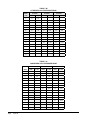
pressure/temperature plugs
The pressure/temperature plugs (P/T plugs) supplied with
the ground water connectors are provided as a means of
measuring flow and temperature (see Figure 10). The
waterflow through the unit can be checked by measuring
the incoming water pressure at the supply pressure P/T and
subtracting the leaving water pressure at the return water
P/T plug. Comparing the differential to the pressure drop/
flow chart (Table 3) will determine the flow rate through
the heat pump.
Example: Model GV51S1 with a measured pressure drop of 5.1 psig is equivalent to 9 GPM flow.
GPM rates higher than the required minimum flow rates will
not be detrimental to performance. However, insufficient
flow can significantly reduce capacity, efficiency and create
nuisance trips of safety controls, and possibly damage to
components in extreme conditions.
NOTE: Pressure/Temperature probes should be lubricated
with a water-based lubricant prior to gently pushing the
probes into the P/T ports to prevent internal damage.
Thermometers, probes and gauges are available for
conducting these tests.
figure 10
pressure temperature ports
Thermometer
NOTE: Slide retaining cap back to expose
double o-rings. Apply petroleum jelly to o-rings
to prevent damage and aid in insertion
Dial face pressure guage
with guage adaptor
40
50
60
70
Retaining cap, hand tighten only
80
30
90
20
100
10
110
0
120
P/T test plug
Pete's
Test plug cap
Barbed 90° adapter
MIS-2622 A
TABLE 3A
GV Series coil pressure drop
Model
GV27S1
GPM
PSID
Ft. Hd.
3
0.1
0.23
4
0.5
5
GV38S1 / GV51S1
PSID
Ft. Hd.
1.15
0.9
2.08
1.2
2.77
1.4
3.23
6
1.7
3.92
2.3
5.31
7
2.3
5.31
3.2
8
3.1
7.15
9
4.1
9.46
GV61S1
PSID
Ft. Hd.
7.38
2
4.61
4.1
9.46
2.5
5.1
11.77
10
6.1
11
GV71S1
PSID
Ft. Hd.
5.77
2
4.61
3.2
7.38
2.4
5.54
14.07
3.9
9.00
2.8
6.46
7.1
16.38
4.7
10.84
3.4
7.84
12
8.2
18.92
5.5
12.69
3.9
9.00
13
9.4
21.69
6.4
14.76
4.5
10.38
14
10.6
24.45
7.3
16.84
5.2
12.00
15
8.1
18.69
5.9
13.61
16
9
20.76
6.7
15.46
17
9.9
22.84
7.4
17.07
8.4
19.38
18
Manual2100-518B
Page
25 of 30
TABLE 3B
GT Series coil pressure drop
Model
GTC48S1
GTC36S1
GPM
PSID
Ft. Hd.
PSID
Ft. Hd.
3
0.1
0.23
4
0.5
1.15
0.9
2.08
5
1.2
2.77
1.4
3.23
6
1.7
3.92
2.3
5.31
7
2.3
5.31
3.2
8
3.1
7.15
9
4.1
9.46
GTC60S1
PSID
Ft. Hd.
7.38
2
4.61
4.1
9.46
2.5
5.77
5.1
11.77
3.2
7.38
10
6.1
14.07
3.9
9.00
11
7.1
16.38
4.7
10.84
12
8.2
18.92
5.5
12.69
13
9.4
21.69
6.4
14.76
14
10.6
24.45
7.3
16.84
15
8.1
18.69
16
9
20.76
17
9.9
22.84
18
TABLE 3C
QW Series coil pressure drop
Model
GPM
PSID
Ft. Hd.
3
0.1
0.23
4
0.5
5
QW4S1
PSID
Ft. Hd.
1.15
0.9
2.08
1.2
2.77
1.4
3.23
6
1.7
3.92
2.3
5.31
7
2.3
5.31
3.2
8
3.1
7.15
9
4.1
9.46
QW6S1
PSID
Ft. Hd.
7.38
2
4.61
4.1
9.46
2.5
5.77
5.1
11.77
3.2
7.38
10
6.1
14.07
3.9
9.00
11
7.1
16.38
4.7
10.84
12
8.2
18.92
5.5
12.69
13
9.4
21.69
6.4
14.76
14
10.6
24.45
7.3
16.84
15
8.1
18.69
16
9
20.76
17
9.9
22.84
18
Manual2100-518B
Page 26 of 30
QW2S1 & QW3S1
troubleshooting
Problem
Water Drips Out
Low Flow / No Flow
Noisey
Pressure Loss
Unit Trips Out on Water Flow
(Low Pressure or High Pressure)
Possible Causes
Checks & Corrections
Condensation
Insulate piping, check for insulation gaps.
Water Leak
Inspect/tighten fittings.
Power Loss
Check power supply from the heat pump.
Blown Circuit Breaker
Reset circuit breaker for flow center in heat pump control box.
Broken or Loose Wires
Replace or tighten wires.
Pump Shaft Stuck
Remove the indication plug and ensure that shaft is rotating.
Air Lock
Flush loop to eliminate air.
Improperly Sized Pump
Add pump capacity.
Defective Pump
Replace.
No Positive Pressure
Check for leaks, add fluid, flush as required and pressurize.
Viscous Solution
Change type of antifreeze.
Loop Freezing or Frozen
Switch thermostat to A/C operation to see if flow improves at warmer temperature.
Add antifreeze and measure freeze protection.
Kink in Loop
Straighten or Replace.
Defective Pump
Replace.
Air in Loop
Flush loop again.
Vibration
Check mounting.
Leak
Repair.
Temperature Change
Not a problem; pressure should vary as temperature changes.
Pipe Expansion
Not a problem; plastic piping relaxing.
Low Flow / No Flow
See Low Flow / No Flow.
Manual2100-518B
Page
27 of 30
ANTIfreeze selection & use
Selection of antifreeze solutions for ground loop
applications requires consideration of many important
factors, which may have long-term implications in regards
to performance and system component life. Each area
of concern leads to a different antifreeze solution. The
fact that there is no “ideal” antifreeze and any choice will
require compromises in one area or another. Some of these
considering factors include:
Safety – The toxicity and flammability of the antifreeze solution.
Thermal Performance – The heat transfer and viscosity effects of the antifreeze.
Cost – The prices vary widely.
Corrosiveness – System materials must be compatible with the antifreeze solution.
Stability – Will the solution require periodic change out or maintenance?
Convenience – Is the solution readily available and easy to transport and install?
Codes – Will the solution meet local/regional/state/
national regulatory standards?
It is highly recommended to utilize pre-mixed antifreeze
solutions where possible to alleviate many installation
problems and extra labor.
The following are some general observations about the
types of antifreeze materials presently being applied in the
geothermal ground loop markets:
Manual2100-518B
Page 28 of 30
Methanol – Considered toxic in pure form, good heat transfer, low to mid-price, flammable in concentrations
greater than 25%, non-corrosive and low viscosity.
Methanol has delivered outstanding performance in ground
loop applications for over 20 years. Its only drawbacks
are toxicity and flammability. Although methanol enjoys
widespread consumer use as windshield washer fluid in even
higher concentrations, some local codes may limit its use in
ground loops. (Note: Do NOT use automotive windshield
washer fluid as antifreeze. Most washer fluids contain
chemicals that will cause foaming.) To increase safety, a
pre-mixed form should be used on the jobsite to increase
the safety factor. Pure methanol can be purchased from any
chemical supplier.
Ethanol – Good heat transfer (lower than methanol),
high price, flammable in concentrations greater than 10%,
non-corrosive and low viscosity. Ethanol in pure form is
considered non-toxic and shows promise as a geothermal
heat transfer fluid. However, the U.S. Bureau of Alcohol,
Tobacco & Firearms (ATF) limit its distribution. All nonbeverage ethanol is required to be denatured and rendered
unfit to drink. Generally, this is done by adding a small
percentage of toxic substances such as methanol, benzene
or gasoline as a denaturant. Many of the denaturants are
difficult to identify by the casual user, and many are not
compatible with polyethylene pipe. Only denatured ethanol
can be purchased for commercial use. The use of ethanol
is not recommended because of the unknown denaturants
included in the solution and their possible toxicity
and damage resulting to polyethylene piping systems.
Denaturing agents that are petroleum based can damage
polyethylene pipe.
ANTIfreeze selection & use (continued)
Potassium Acetate (GS4) – Non-toxic, good heat
transfer, high price, non-corrosive with added inhibitors,
low viscosity. Due to its low surface tension, Potassium
Acetate has been known to leak through mechanical
fittings and certain thread sealants. A variant of the salt
family, it can be extremely corrosive when exposed to air.
Potassium Acetate is not recommended in ground loop
applications due to the leaking and (ultimately) corrosion
problems associated with it.
Propylene Glycol – Non-toxic, non-corrosive,
expensive, hard to handle when cold, poorest heat transfer,
has formed “slime-type” coatings inside system piping.
Propylene Glycol is acceptable in systems anticipating
loop temperatures no colder than 40°F (4.4°C). These
systems typically use antifreeze because of low ambient
conditions (outside plumbing or cooling tower, etc.).
When loop temperatures are below 40°F, the fluid becomes
very difficult to pump and heat transfer characteristics
suffer greatly. Only food grade propylene glycol is
recommended to prevent the corrosion inhibitors from
reacting with local water causing “slime-type” coatings
inside heat exchangers. If propylene glycol must be
used (code requirements), careful consideration of loop
Reynolds numbers, pump selection and pressure drop must
be considered.
Note: Consult with your local distributor if you have
questions regarding antifreeze selection and any comments
to report about problems or success with any particular
methods in your area.
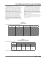
TABLE 4
fluid volume
Approximate Fluid Volume per 100’ (10 Meters) of Pipe
Size
Volume
(u.s. gallon/100'pipe)
Volume
(Liters/10 meters)
Copper
1" CTS
4.1
15.5
Copper
1-1/4" CTS
6.4
24.2
Copper
1-1/2" CTS
9.2
34.8
Polyethylene
3/4" - IPS SDR 11
3.0
11.4
Polyethylene
1" - IPS SDR 11
4.7
17.8
Polyethylene
1-1/4" - IPS SDR 11
7.5
28.4
Polyethylene
1-1/2" - IPS SDR 11
9.8
37.1
Polyethylene
2" - IPS SDR 11
15.4
58.3
Type
TABLE 5
percentages by volume
Antifreeze Percentages by Volume
Type
Minimum Temperature for Freeze Protection
10°F (-12.2°C)
15°F (-9.4°C)
20°F (-6.7°C)
25°F (-3.9°C)
Methanol
25%
21%
16%
10%
Ethanol *
29%
25%
20%
14%
100% USP
Food Grade
Propylene
Glycol
27%
24%
20%
13%
* Must not be denatured with any petroleum based product.
Manual2100-518B
Page
29 of 30
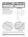
WARNING
WARNING
Always use properly marked vehicles (D.O.T.
Always use
properly
marked vehicles (D.O.T.
placards)
and
clean/suitable/properly
marked
placards) containers
and clean/suitable/properly
marked
identified
for handling flammable
identified containers
handling
flammable
antifreeze
mixtures. for
Post
and advise
those
antifreeze
mixtures.
Post and
those
on
the jobsite
of chemical
use advise
and potential
on the jobsite
of chemical
use and potential
dangers
of handling
and storage.
dangers of handling and storage.
antifreeze verification
ANTIFREEZE VERIFICATION
caution
CAUTION
Always obtain MSDS (material safety data
Always obtain
MSDS (material
safety
data
sheets)
for all chemicals
used in
ground
loop
sheets)
for
all
chemicals
used
in
ground
loop
applications - including chemicals used as
applications - including chemicals used as
antifreeze.
antifreeze.
figure 11
FIGURE
11
density
verification
DENSITY
VERIFICATION
for Solution strength
for SOLUTION STRENGTH
Both Glycol and Alcohol based antifreeze solutions can
Both Glycol and Alcohol based antifreeze solutions can be
be verified to the specific percentage of volume within the
verified to the specific percentage of volume within the
ground loop system. One of the easiest ways to check this
ground loop system. One of the easiest ways to check this
is through use of a Hydrometer to check the specific density
is through use of a Hydrometer to check the specific
of the ground loop fluid and comparing these to the charts
density of the ground loop fluid and comparing these to the
supplied by the antifreeze manufacturer (see Figure 11).
charts supplied by the antifreeze manufacturer (see Figure
Hydrometers
can be purchased from your local distributor
11).
and are also available through national wholesalers.
Hydrometers can be purchased from your local distributor
and are also available through national wholesalers.
MIS-2666
MIS-2666
TABLE 6
TABLE 7
It is recommended that IGSHPA design and specifications are utilized for Loop Design, Pipe Manifolding and Hot Fusion
It is recommended that IGSHPA design and specifications are utilized for Loop Design, Pipe Manifolding and Hot Fusion
operations.
operations.
There are many available software programs available to aid with loop design parameters. Your local loop material or equipment
There are
many
available
softwareavailable.
programsTechnical
availableService
to aid with
design parameters.
local
loop
supplier
may
have
this technology
has loop
the capability
to assist youYour
in this
area
as material
well, but or
it is on a
equipment
may
have this technology available. Technical Service has the capability to assist you in this area as well,
first
come - supplier
first serve
basis.
but it is on a first come - first serve basis.
Manual2100-518B
Manual 30
2100-518A
Page
of 30
Page
30 of 30