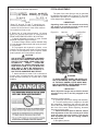
1
BUSH HOG
®
2010/2012
Rotary Cutter
Operator’s Manual
ASSEMBLY l OPERATION l MAINTENANCE
05/09 Rev.1
$4.00
50044275
CONGRATULATIONS!
You have invested in the best implement of its type on the market today.
The care you give your Bush Hog implement will greatly determine your satisfaction with
its performance and its service life. We urge a careful study of this manual to provide you
with a thorough understanding of your new implement before operating, as well as suggestions for operation and maintenance.
If your manual should become lost or destroyed, Bush Hog will be glad to provide you with
a new copy. Order from Bush Hog, 2501 Griffin Ave., Selma, Alabama, 36703. Most of our
manuals can also be downloaded from our website at www.bushhog.com.
As an authorized Bush Hog dealer, we stock genuine Bush Hog parts which are manufactured with the same precision and skill as our original equipment. Our trained service personnel are well informed on methods required to service Bush Hog equipment, and are
ready and able to help you.
Should you require additional information or assistance, please contact us.
YOUR AUTHORIZED
BUSH HOG DEALER
BECAUSE BUSH HOG MAINTAINS AN ON GOING
PROGRAM OF PRODUCT IMPROVEMENT, WE
RESERVE THE RIGHT TO MAKE IMPROVEMENTS IN
DESIGN OR CHANGES IN SPECIFICATIONS WITHOUT INCURRING ANY OBLIGATION TO INSTALL
THEM ON UNITS PREVIOUSLY SOLD.
BECAUSE OF THE POSSIBILITY THAT SOME PHOTOGRAPHS IN THIS MANUAL WERE TAKEN OF PROTOTYPE MODELS, PRODUCTION MODELS MAY
VARY IN SOME DETAIL. IN ADDITION, SOME PHOTOGRAPHS MAY SHOW SHIELDS REMOVED FOR
PURPOSES OF CLARITY. NEVER OPERATE THIS
IMPLEMENT WITHOUT ALL SHIELDS IN PLACE.
2010/2012 SERIES ROTARY CUTTERS
TABLE OF CONTENTS
SECTION/PARA
PAGE
Warranty ................................................2
Dealer Preparation Check List ...............3
Safety Alert Symbols..............................4
Safety Precautions.................................5
Federal Laws and Regulations ..............6
I. INTRODUCTION & DESCRIPTION ......7
1-1 Introduction ......................................7
1-2 Description.......................................7
II. PREPARATION FOR USE ....................8
2-1 Attaching To Tractor (Lift Models &
Semi-Mount Models .........................8
2-2 Attaching To Tractor (Pull Models) ..9
III.OPERATING INSTRUCTIONS............11
3-1 General Safety...............................11
3-2 Transporting...................................11
3-3 Adjusting Cutting Height ................11
3-4 Operation .......................................11
SECTION/PARA
PAGE
IV.MAINTENANCE..................................12
4-1 Maintenance Check List ................12
4-2 Lubrication .....................................12
4-3 Blade Replacement .......................13
4-4 Gearbox Removal..........................13
4-5 Gearbox Installation.......................14
4-6 Slip Clutch Operational Check.......14
4-7 Slip Clutch Adjustment..................14
4-8 Troubleshooting ............................15
V. ASSEMBLY.........................................15
5-1 Lift Models.....................................16
5-2 Semi-Mount Hitch Models.............27
5-3 Safety Chain Installation ...............17
5-4 Rear Band Installation...................18
5-5 Front Belting..................................18
5-6 Safety Tow Chain..........................18
5-7 Pull Model Assembly.....................19
Safety Decals ................................20
Torque Specifications....................21
RETAIL CUSTOMER’S RESPONSIBILITY
UNDER THE BUSH HOG WARRANTY
It is the Retail Customer and/or Operator’s responsibility to read the Operator’s Manual, to
operate, lubricate, maintain and store the product in accordance with all instructions and
safety procedures. Failure of the operator to read the Operator’s Manual is a misuse of this
equipment.
It is the Retail Customer and/or Operator’s responsibility to inspect the product and to have
any part(s) repaired or replaced when continued operation would cause damage or excessive wear to other parts or cause a safety hazard.
It is the Retail Customer’s responsibility to deliver the product to the authorized Bush Hog
Dealer, from whom he purchased it, for service or replacement of defective parts which are
covered by warranty. Repairs to be submitted for warranty consideration must be made within forty-five (45) days of failure.
It is the Retail Customer’s responsibility for any cost incurred by the Dealer for traveling to or
hauling of the product for the purpose of performing a warranty obligation or inspection.
1
LIMITED WARRANTY
OOOOOOOOOOOOOOOOOOOOOOOOOOOOOOO
Bush Hog warrants to the original purchaser of any new Bush Hog equipment, purchased from an
authorized Bush Hog dealer, that the equipment be free from defects in material and workmanship for a period
of one (1) year for non-commercial, state, and municipalities’ use and ninety (90) days for commercial use from
date of retail sale. The obligation of Bush Hog to the purchaser under this warranty is limited to the repair or
replacement of defective parts.
Replacement or repair parts installed in the equipment covered by this limited warranty are warranted
for ninety (90) days from the date of purchase of such part or to the expiration of the applicable new equipment warranty period, whichever occurs later. Warranted parts shall be provided at no cost to the user at an
authorized Bush Hog dealer during regular working hours. Bush Hog reserves the right to inspect any equipment or parts which are claimed to have been defective in material or workmanship.
DISCLAIMER OF IMPLIED WARRANTIES & CONSEQUENTIAL DAMAGES
Bush Hog’s obligation under this limited warranty, to the extent allowed by law, is in lieu of all warranties, implied or expressed, INCLUDING IMPLIED WARRANTIES OF MERCHANTABILITY AND FITNESS
FOR A PARTICULAR PURPOSE and any liability for incidental and consequential damages with respect to
the sale or use of the items warranted. Such incidental and consequential damages shall include but not be
limited to: transportation charges other than normal freight charges; cost of installation other than cost
approved by Bush Hog; duty; taxes; charges for normal service or adjustment; loss of crops or any other loss of
income; rental of substitute equipment, expenses due to loss, damage, detention or delay in the delivery of
equipment or parts resulting from acts beyond the control of Bush Hog.
THIS LIMITED WARRANTY SHALL NOT APPLY:
1. To vendor items which carry their own warranties, such as engines, tires, and tubes.
2. If the unit has been subjected to misapplication, abuse, misuse, negligence, fire or other accident.
3. If parts not made or supplied by Bush Hog have been used in connection with the unit, if, in the sole judgement of Bush Hog such use affects its performance, stability or reliability.
4. If the unit has been altered or repaired outside of an authorized Bush Hog dealership in a manner
which, in the sole judgement of Bush Hog, affects its performance, stability or reliability.
5. To normal maintenance service and normal replacement items such as gearbox lubricant, hydraulic fluid,
worn blades, or to normal deterioration of such things as belts and exterior finish due to use or
exposure.
6. To expendable or wear items such as teeth, chains, sprockets, belts, springs and any other items that in the
company’s sole judgement is a wear item.
NO EMPLOYEE OR REPRESENTATIVE OF BUSH HOG IS AUTHORIZED TO CHANGE THIS LIMITED
WARRANTY IN ANY WAY OR GRANT ANY OTHER WARRANTY UNLESS SUCH CHANGE IS MADE IN
WRITING AND SIGNED BY BUSH HOG’S SERVICE MANAGER, 2501 GRIFFIN AVE., SELMA, ALABAMA
36703.
OOOOOOOOOOOOOOOOOOOOOOOOOOOOOOO
Record the model number, serial number and date
purchased. This information will be helpful to your
dealer if parts or service are required.
MODEL NUMBER
SERIAL NUMBER
MAKE CERTAIN THE WARRANTY HAS BEEN
FILED WITH BUSH HOG / SELMA, ALABAMA .
DATE OF RETAIL SALE
2
DEALER PREPARATION CHECK LIST
2010 / 2012 SERIES ROTARY CUTTERS
BEFORE DELIVERING MACHINE — The following check list should be completed.
Use the Operator’s Manual as a guide.
r
r
r
r
r
r
r
r
r
1. Assembly completed.
2. Gearbox filled with oil.
3. All fittings lubricated.
4. All shields in place and in good condition.
5. All fasteners torqued to specifications given in Torque Chart.
6. Slip clutches have been checked for proper operation.
7. All decals in place and readable. (See decal page.)
8. Overall condition good (i.e. paint, welds)
9. Operators manual has been delivered to owner and he has been instructed
on the safe and proper use of the cutter.
10. Warranty information registered with Bush Hog.
r
r 11. Purchaser or dealer elects to delete deflectors. (front chains)
Explanation:
WARNING
Deflector kit or chain shielding is standard equipment. Must be used for all non-agricultural uses or in areas where the possibility of thrown objects could be hazardous to
persons or property. Use 5/16” double row highway chains for all roadside mowing
operations.
Dealer’s
Signature
Purchaser’s
Signature
THIS CHECKLIST TO REMAIN IN OWNER’S MANUAL
It is the responsibility of the dealer to complete the procedures listed
above before delivery of this implement to the customer.
3
Safety Alert Symbol
This Safety Alert Symbol means: “ATTENTION! BECOME ALERT!
YOUR SAFETY IS INVOLVED!”
This symbol is used to call attention to safety
precautions that should be followed by the
operator to avoid accidents. When you see this
symbol, carefully read the message that follows
and heed its advice. Failure to comply with
safety precautions could result in death or serious bodily injury.
Safety Signs
Signal Words
The signal words DANGER, WARNING, AND CAUTION are used on the equipment safety signs. These words
are intended to alert the viewer to the existence and the degree of hazard seriousness.
This signal word indicates a potentially hazardous situation
which, if not avoided, will result in death or serious injury.
White letters on RED
This signal word indicates a potentially hazardous situation
which, if not avoided, could result in death or serious injury
It may also be used to alert against unsafe practices.
Black letters on ORANGE
This signal word indicates a potentially hazardous situation exist
which, if not avoided, may result in minor or moderate injury.
It may also be used to alert against unsafe practices.
Black letters on YELLOW
4
IMPORTANT SAFETY PRECAUTIONS
This symbol is used to call attention to safety
precautions that should be followed by the
operator to avoid accidents. When you see this
symbol, carefully read the message that follows
and heed its advice. Failure to comply with safety precautions could result in serious bodily
injury.
In addition to the design and configuration of equipment, hazard control and accident prevention are dependent
upon the awareness, concern, prudence and proper training of personnel in the operation, transport, maintenance
and storage of equipment. Lack of attention to safety can result in accident, personal injury, reduction of efficiency
and worst of all—loss of life. Watch for safety hazards and correct deficiencies promptly. Use the following safety
precautions as a general guide to safe operations when using this machine. Additional safety precautions are
used throughout this manual for specific operating and maintenance proce-dures. Read this manual and review
the safety precautions often until you know the limitations.
1.
Read the Operator’s Manual. Failure to read the Operator’s Manual is considered a misuse of this equipment.
2.
Become familiar with all the machine’s controls and all the caution, warning and danger decals affixed to the
machine before attempting to start or operate.
3.
Before starting or operating the machine, make a walk around inspection and check for obvious defects such
as loose mounting bolts and damaged components. Correct any deficiency before starting.
4.
Do not allow children to operate the cutter. Do not allow adults to operate it without proper instruction.
5.
Do not carry passengers.
6.
Keep the area of operation clear of all persons, particularly small children and pets. The operator
should cease mowing whenever anyone comes within the operating area.
7.
Clear the work area of objects which might be picked up and thrown.
8.
Use a piece of cardboard or wood rather than hands to search for hydraulic leaks. Escaping hydraulic oil
under pressure can penetrate skin. If fluid is injected into the skin, it must be surgically removed within a few
hours by a doctor familiar with this form of injury or gangrene may result.
9.
Do not operate without all guards and shields in place and in good condition.
10. Lower implement to ground, stop tractor engine, apply parking brake, and allow blades to completely stop
before leaving the tractor.
11. Keep hands and feet away from blades.
12. This cutter is not to be operated along highways or in any area where people may be present unless
all sides of the unit are enclosed by permanent bands, safety chains or other factory approved safety shields
that are in good repair.
13. Wear personal protective equipment such as, but not limited to, protection for eyes, ears, feet, hands and
head when operating or repairing the equipment. Do not wear loose clothing or jewelry that may catch on
equipment moving parts.
14. When performing adjustments or maintenance on the cutter, first lower it to the ground or block it securely at
a workable height.
15. Never stand between tractor and cutter while tractor is being backed to the cutter hitch.
16. Reduce speed when transporting cutter to avoid bouncing and momentary loss of steering.
17. Use tractor flashing warning lights, day or night, when transporting cutter on road or highways unless
prohibited by law.
18. In the event that someone other than yourself will operate this equipment we firmly suggest that all
SAFETY references be discussed prior to operation.
19. It is recommended that tractor be equipped with Rollover Protective System (ROPS) and seat belt
be used in all mowing operations.
5
IMPORTANT FEDERAL LAWS AND REGULATIONS* CONCERNING
EMPLOYERS, EMPLOYEES AND OPERATIONS.
*(This section is intended to explain in broad terms the concept and effect of the following federal laws and
regulations. It is not intended as a legal interpretation of the laws and should not be considered as such).
U.S. Public Law 91-596 (The Williams-Steiger Occupational and Health Act of 1970) OSHA
This Act Seeks:
“...to assure so far as possible every working man and woman in the nation safe and healthful working
conditions and to preserve our human resources...”
DUTIES
Sec. 5 (a) Each employer—
(1) shall furnish to each of his employees employment and a place of employment
which are free from recognized hazards that are causing or are likely to cause
death or serious physical harm to his employees;
(2) shall comply with occupational safety and health standards promulgated under
this Act.
(b) Each employee shall comply with occupational safety and health standards
and all rules, regulations and orders issued pursuant to this Act which are
applicable to his own actions and conduct.
OSHA Regulations
Current OSHA regulations state in part: “At the time of initial assignment and at least annually thereafter, the
employer shall instruct every employee in the safe operation and servicing of all equipment with which the
employee is, or will be involved.” These will include (but are not limited to) instructions to:
Keep all guards in place when the machine is in operation;
Permit no riders on equipment;
Stop engine, disconnect the power source, and wait for all machine movement to stop before
servicing, adjusting, cleaning or unclogging the equipment, except where the machine must be
running to be properly serviced or maintained, in which case the employer shall instruct employees
as to all steps and procedures which are necessary to safely service or maintain the equipment.
Make sure everyone is clear of machinery before starting the engine, engaging power, or operating
the machine.
EMPLOYEE TRACTOR OPERATING INSTRUCTIONS:
1. Securely fasten your seat belt if the tractor has a
ROPS.
5. Watch where you are going, especially at row
ends, on roads, and around trees.
2. Where possible, avoid operating the tractor near
ditches, embankments, and holes.
6. Do not permit others to ride.
7. Operate the tractor smoothly - no jerky turns,
starts, or stops.
3. Reduce speed when turning, crossing slopes, and
on rough, slick, or muddy surfaces.
8. Hitch only to the drawbar and hitch points recommended by tractor manufacturers.
4. Stay off slopes too steep for safe operation.
9. When tractor is stopped, set brakes securely and
use park lock if available.
Child Labor Under 16 Years Old
Some regulations specify that no one under the age of 16 may operate power machinery. It is your
responsibility to know what these regulations are in your own area or situation. (Refer to U.S. Dept. of
Labor, Employment Standard Administration, Wage & Home Division, Child Labor Bulletin #102.)
6
SECTION I
INTRODUCTION AND DESCRIPTION
a smooth, even cut and will swing back when a stationary object is hit. A slip clutch on the input driveline and rubber couplings on the cross shafts also
dampen the impact of the blades hitting a stationary
object. Shock absorbing rubber cushions are mounted between the axle arm and axle arm mounting
bracket to reduce shock loads during operation and
transporting. These cutters are available with either
pull, semi-mount, or three point hitches.
1-1 INTRODUCTION
We are pleased to have you as a Bush Hog customer. Your Model 2010/2012 Series Rotary Cutter
has been carefully designed to give maximum service with minimum down time. This manual is provided to give you the necessary operating and maintenance instructions for keeping your rotary cutter in
top operating condition. Please read this manual
thoroughly. Understand what each control is for and
how to use it. Observe all safety precautions
decaled on the machine and noted throughout the
manual for safe operation of implement. If any assistance or additional information is needed, contact
your authorized Bush Hog dealer.
Table 1-1 Specifications
2010
2012
Length (Pull)
147 in.
160 in.
Length (Lift)
108 in.
120 in.
Width
123 in.
146 in.
Cutting Width
117 in.
141 in.
Cutting Height
2-12 in.
2-12 in.
Minimum Tractor HP
(Pull & Semi)
40
50
(Lift)
60
70
Blade Tip Speed
@ 540 rpm
15777 ft./min. 15490 ft./min.
@1000 rpm
15708 ft./min. 15422 ft./min.
*Approx Weight (Pull)
2165 lbs.
2513 lbs.
*Approx Weight (Semi) 1817 lbs.
2120 lbs.
*Approx Weight (Lift)
1922 lbs
2225 lbs.
NOTE
All references made to right, left, front, rear, top or
bottom is as viewed facing the direction of travel with
implement properly attached to tractor.
1-2 DESCRIPTION
The Model 2010/2012 Series Rotary Cutters, Figure
1-1, are medium duty implements designed for cutting stalks, pasture clipping and other large, maintained acreages. Free swinging uplift blades provide
*Unit equipped with front belting and rear bands
2012 Lift Type
Figure 1-1
2012 Pull Type
with Light Kit
7
SECTION II
PREPARATION FOR USE
B. Raise and lower cutter to dettermine position
with shortest distance between the tractor PTO shaft
and gearbox input shaft.shut down tractor leaving
cutter in position of shortest distance. SECURELY
BLOCK CUTTER IN POSITION.
C. Pull driveline apart. Attach outer (female) section to tracator PTO shaft. Pull on driveline section to
be sure yoke locks into place.
D. Hold driveline sections paralled to each other
to determine if too long. Each section should end
approximately 3 inches (76mm) short of reaching
universal joint shield mark on opposite section.
(Figure 2-2) Do this for both sections.
E. Raise and lower cutter to determine position
with greatest distance between PTO shaft and gearbox input shaft. Shut down tractor leaving cutter in
position of greatest distance. SECURELY BLOCK
CUTTER IN POSITION.
F. Hold driveline sections parallel to each other
and check for minimum 6 inches (152mm) overlap.
(Figure 2-3) If driveline has been marked for cutting,
overlap will be the distance between two marks. If
driveline has less than minimum overlap, DO NOT
USE. Contact authorized Bush Hog dealer.
2-1 ATTACHING TO TRACTOR
Lift & Semi-Mount
WARNING
NEVER STAND BETWEEN TRACTOR AND
CUTTER WHILE TRACTOR IS BEING
BACKED TO HITCH
WARNING
ADDITIONAL TRACTOR FRONT BALLAST
MAY BE NEEDED FOR STABLE OPERATION AND TRANSPORT OF CUTTER. SEE
TRACTOR OPERATORS MANUAL FOR
RECOMMENDED WEIGHTS. USE ROPS
(ROLLOVER PROTECTIVE STRUCTURE)
AND SEATBELT EQUIPPED TRACTORS
FOR MOWING OPERATIONS. BUCKLE UP
SEAT BELT TO AVOID ACCIDENTAL FALL
AND POSSIBLE INJURY FROM CUTTER.
IMPORTANT
The minimum recommended horsepower for operating a lift model 2010 cutter is 60 and for a semimount model is 40. The minimum recommended
horsepower for model 2012 lift models is 70 and for
a semi-mount is 50.
NOTE
If driveline is correct length, omit steps “G” through
“J” and proceed to step “K”.
A. Attach cutter to tractor 3-point hitch as
described in tractor operator’s manual. Arrange
bushings on hitch pins as shown in Figure 2-1 to
accomodate different size hitches.
Figure 2-2 Marking Shield
Figure 2-1 Lift Pin Bushing
Cat.II Std.
Cat. III Quick
Cat. III Std.
Cat. II Quick
NOTE
Move bolt and bushing to
middle hole for
Cat. III Quick Hitch
Cat. II Quick
Cat. III Std.
Figure 2-3
Cat. III Quick
Minimum Overlap
Cat. II Std.
NOTE
Due to the many variations in tractor/implement
hitch points and corresponding differences in
distances between tractor PTO shafts and
implement input shafts, drivelines may need to
be shortened as described in the following steps.
8
Figure 2-4 Cutting Shield
G. Clamp driveline in a padded vice to prevent
damage to shield. Cut off shield where marked.
(Figure 2-4)
H. Using cut off section of shield as a guide, cut
shaft the same amount . (Figure 2-5)
I. Repeat steps “G” and “H” to other driveline
section.
J. Deburr ends of driveline sections and clean
away all chips and filings. (Figure 2-6)
K. Apply multi-purpose grease to outside of male
driveline section. Assemble driveline and install on
tractor and cutter. Pull on each driveline section to
be sure yokes lock into place. Make certain driveline
shielding is in place and in good condition.
DANGER
MAKE CERTAIN DRIVELINE YOKES ARE
SECURELY FASTENED. FAILURE TO DO
SO MAY RESULT IN SERIOUS INJURY.
CAUTON
DO NOT USE A PTO ADAPTER. USE OF
PTO ADAPTER CAN CAUSE EQUIPMENT
DAMAGE AND PERSONAL INJURY.
Figure 2-5 Cutting Shaft
L. Raise cutter off ground and adjust lower lift
arms to level cutter right to left. Refer to tractor operator’s manual.
M. Connect and/or adjust tractor stabilizer bars,
sway blocks, sway chains or equivalent to prevent
side sway. Refer to tractor operator’s manual.
N. Install tractor front weights as recommended
by tractor manufacturer to provide ample stability
during operation.
O. (Lift Models) With cutter in work position,
adjust tractor top link as necessary to position floating link in center of slot as shown in Figure 2-7.
Figure 2-7 Floating Link
Slot
Figure 2-6 Deburring
2-2 ATTACHING TO TRACTOR (Pull)
IMPORTANT
The minimum recommended horsepower for operating a pull model 2010 cutter is 40. A pull model 2012
requires 50 horsepower.
A. Adjust tractor drawbar length to dimension
shown in Figure 2-8. Incorrect drawbar length will
change angle of driveline causing possible damage
to universal joints. See tractor operator’s manual for
drawbar adjustment procedures.
9
Figure 2-8 Tractor Drawbar Adjustment
PITCH ADJUSTMENT
The pitch of the cutter (front to rear) is controlled
by adjusting the linkage rods (Figure 2-9). The pitch
adjustment is primarily for compensating for the different height tractor drawbar.
NOTE
Steps “B” through “D” and “F” should be performed only when the cutter is being attached to
a tractor for the first time or if the cutter needs to
be leveled from front to rear.
! IMPORTANT !
Operating cutter with rear lowered excessively
will result in an uneven cut and could cause
rapid blade, skid and driveline wear.
Figure 2-9
B. Raise rear of cutter approximately 1-2 inches
higher off ground than front of cutter.BLOCK
FRONT AND REAR SECURELY IN POSITION.
C.Attach jackstand to tongue of cutter. Extend
jackstand to support weight of tongue.
D. Connect tongue hitch to tractor drawbar using
a 1 inch diameter approved pin with lynch pin retainer or equivalent.
E.If equipped with hydraulic cylinder, route
hydraulic line through hose holder rod and connect
to tractor remote hydraulic quick couplers. Make
certain hydraulic line is not kinked or twisted.
Jam Nut
Leveling Rod
CAUTION
USE A PIECE OF CARDBOARD OR WOOD
RATHER THAN HANDS AND WEAR EYE
PROTECTION WHEN SEARCHING FOR
HYDRAULIC
LEAKS.
ESCAPING
HYDRAULIC OIL UNDER PRESSURE CAN
PENETRATE SKIN. IF OIL IS INJECTED
INTO SKIN, IT MUST BE SURGICALLY
REMOVED WITHIN A FEW HOURS BY A
DOCTOR OR GANGRENE MAY RESULT.
Tongue Lug
F. Attach driveline to tractor. Pull on driveline to
be sure yoke is locked securely into place. Make
certain driveline shielding is in place and in good
condition.
Clevis
WARNING
TO AVOID SERIOUS INJURY OR DEATH: DO
NOT PLACE HANDS, FEET OR OTHER PARTS
OF THE BODY UNDER CUTTER WHILE MAKING ADJUSTMENTS. NEVER MAKE ADJUSTMENTS WITH CUTTER OPERATING.
! IMPORTANT !
Never adjust the linkage rods so that the threaded ends of any rod is not fully engaged in the
clevises.
Adjust the pitch as follows:
A. Loosen jam nut on each linkage rod assembly.
B. Turn the leveling rods to lengthen or shorten
the assemblies. Shortening the rods will raise the
front of the cutter and lenghtening the rods will lower
the front of the cutter. While adjusting, alternate
from one rod to the other.
C. When the desired pitch is attained, make a
final adjustment of the rods so that each will be
under the same amount of tension. This may be
done by tapping the rods and “tuning” them to
the same sound.
D. Re-tighten jamnuts.
10
SECTION III
OPERATING INSTRUCTIONS
3-1 GENERAL SAFETY
B. Make certain jackstand is stored for work.
(Pull units only)
C. Start tractor per tractor operator’s manual. Lower
cutter to desired cutting height. On lift models, floating
link should be positioned as shown in Figure 2-7.
Only qualified people familiar with this operator’s
manual should operate this machine. Operator
should wear hard hat, safety glasses and safety
shoes. The operator should read, understand and
practice all safety messages shown on the caution,
warning and danger decals affixed to the cutter to
avoid serious injury or death. Use ROPS (Rollover
Protective Structure) and seatbelt equipped tractors
for mowing operations. Buckle up seat belt to avoid
accidental fall and possible injury from cutter. Before
beginning operation, clear work area of any objects
that may be picked up and thrown. Check for ditches, stumps, holes or other obstacles that could upset
tractor or damage cutter. Always turn off tractor
engine, set parking brake, lower cutter to ground and
allow blades to come to a complete stop before leaving tractor operator’s seat.
DANGER
STAY CLEAR OF ROTATING DRIVELINES.
DO NOT OPERATE WITHOUT DRIVELINE
SHIELDS IN PLACE AND IN GOOD CONDITION. FAILURE TO HEED THESE WARNINGS
MAY RESULT IN PERSONAL INJURY OR
DEATH.
DANGER
STAND CLEAR OF ROTATING CUTTER
BLADES UNTIL ALL MOTION HAS STOPPED.
TO AVOID ACCIDENTAL FALL AND POSSIBLE INJURY FROM CUTTER, IT IS RECOMMENDED THAT TRACTOR BE EQUIPPED
WITH ROLLOVER PRETECTIVE SYSTEM AND
THAT A SEAT BELT BE USED FOR ALL
OPERATIONS.
3-2 TRANSPORTING
Turn off PTO drive and fully raise cutter before transporting. When implement is transported on road or
highway, day or night, use tractor flashing warning
lights unless prohibited by law. A slow moving vehicle sign (SMV) must be visible from the rear by
approaching vehicles. Do not exceed 15 mph.
D. With tractor at idle speed, engage PTO drive.
Advance throttle to correct operating speed (540
or 1000 PTO rpm) for implement.
WARNING
3-3 CUTTING HEIGHT ADJUSTMENT
ALL ROTARY CUTTERS HAVE THE ABILITY
TO DISCHARGE OBJECTS AT HIGH SPEEDS
WHICH COULD RESULT IN SERIOUS INJURY
TO BYSTANDERS OR PASSERS-BY.
The cutter should be operated at the highest position
which will give desired cutting results. This will help
prevent blades from striking ground, reducing blade
wear and undue strain on the machine. For best
results under heavier cutting conditions, always set
the front of cutter approximately 2 inches lower than
the rear. This tilt decreases horsepower requirements and increases potential ground speed. When
fine shredding is desired, adjust cutter deck level or
slightly lower in the rear. This will keep the foilage
under cutter until thoroughly shredded. More power
is required for shredding.
DO NOT OPERATE CUTTER IN VACINITY OF
OTHER PERSONS. CEASE MOWING WHENEVER ANYONE COMES WITHIN THE OPERATING AREA.
KEEP ENCLOSED SIDES, PERMANENT
BANDS, BELTING, HIGHWAY CHAINS OR
OTHER FACTORY APPROVED DISCHARGE
SHIELDS IN PLACE AND IN GOOD CONDITION.
Two methods of height adjustment are available - a
hydraulic cylinder or a ratchet. Both methods give a
cutting height of 2 - 12 inches. Stop collars are provided with the hydraulic cylinders. These collars may
be placed around cylinder rod to stop cylinders at
desired cutting height.
E. Place tractor in low gear and begin cutting. Tractor forward speed should be controlled by
gear selection, not engine speed. For maximum
cutting efficiency, forward speed should allow cutter to maintain a constant maximum blade speed.
Always cut up and down the face of slopes, never
across.
When cutting height is adjusted on pull type cutters,
the self-leveling linkage will adjust tongue height
automatically. The front to rear slope of cutter deck
can be changed by adjusting the length of the leveling rod as described in “Pitch Adjustment”.
If tractor engine stalls, do not slip tractor clutch to
allow engine to regain speed as this will exert undue
strain on the implement drivetrain. When stalling
occurs, disengage tractor PTO drive, move to a cut
area, set throttle to idle, then re-engage PTO drive.
Select lower tractor gear if cutter stalls continuously.
3-4 OPERATION
A. Perform BEFORE EACH USE maintenance
listed in paragraph 4-1.
11
SECTION IV
MAINTENANCE
2. Inspect cutter for worn or damaged components.
Repair or replace before next use. Any replacement components installed during repair shall
include the components current safety decals
specified by the manufacturer to be affixed to
the component.
3. Store cutter in a dry place.
4-1 MAINTENANCE CHECK LIST
Perform scheduled maintenance as outlined below.
Lower implement to ground, turn off tractor, and set
parking brake before doing maintenance inspections
or work. Some checks may require raising machine
off ground and supporting with blocks. All bolts
should be torqued as indicated in torque chart
unless otherwise indicated.
4-2 LUBRICATION (Figure 4-1 a, b, c, d)
WARNING
NOTE
The multi-purpose grease referenced in this section
is an NLGI Grade 2 type grease.
THE CUTTER CAN FALL FROM
HYDRAULIC SYSTEM RELEASE. TO
AVOID SERIOUS INJURY OR DEATH,
SECURELY
SUPPORT
CUTTER
BEFORE WORKING UNDERNEATH.
BEFORE EACH USE
1. Driveline Universal Joints - Apply multi-purpose
grease with grease gun.
2. Driveline Guard - Apply 2-3 shots of multipurpose grease with grease gun to plastic fitting.
3. Caster Pivot - Apply multi-purpose grease with
grease gun.
4. Constant Velocity (CV) Joint - Position CV joint
as straight as possible to be sure grease will
penetrate to ball joint. Lubricate the central body
with a minimum of 30 shots of grease every 8
hours. Lubricate telescoping members with 10
shots every 8 hours and clean telescoping
members every 40 hours and completely coat
with grease.
5. CV Driveline - Apply 8-10 shots of multi-purpose
grease to grease fitting accessible behind
U-joint cross, on end of shaft.
6. Gearboxes - Check gearboxes before first
use to make certain they have been filled
with oil and the vented fill plugs have been
installed. Thereafter, check before each use,
Figure 4-1 b (4)
(1)
(1)
(1)
BEFORE EACH USE
1. Perform BEFORE EACH USE lubrication per
paragraph 4-2.
2. Check blades and spindles to be sure that no for
eign objects such as wire or steel strapping
bands are wrapped around them.
3. Inspect blades for wear. Replace if necessary
per paragraph 4-3. Always replace both blades
with two blades equal in weight. Use only genuine Bush Hog replacement parts.
4. Check blade bolts for tightness. Tighten to
600 ft./lbs.
5. Make certain all shields are in place and in good
condition. Repair or replace any missing or damaged shields.
6. Inspect wheel(s) for wear, damage or foreign
objects. Repair or replace if necessary.
7. Check tractor tire air pressure. Refer to tractor
operator’s manual.
8. During operation, listen for abnormal sounds
which might indicate loose parts, damaged bearings or other damage. Correct any deficiency
before continuing operation.
AFTER EACH USE
1. Clean all debris from machine especially underside of deck and affixed safety decals. Replace
any missing or illegible decals.
Figure 4-1 a
(5)
(2) Before Each Use
Figure 4-1c
(3) Before Each Use
(1) Before Each Use
To Remove Yoke Shield:
Turn slotted head 90° with
screwdriver, remoce turn
screw and slide cover back
(6) 40 Hours
12
(7) 20 Hours
Figure 4-1 c
(9) 40 Hours
(6) Before Each Use
(8) 40 Hours
4-4 GEARBOX REMOVAL
adding EP80W-90 gear oil, if necessary, to
bring oil level to check plug on center and
outer gearboxes.
20 HOURS
7. Driveline (Lift & Swing Hitch) - Disconnect
driveline, pull the two sections apart, apply
thin coat of multi-purpose grease to outside
of inner (male) section. Reassemble sections and install. Pull each section to be
sure driveline and shields are securely con
nected. Make certain PTO shielding is in
good condition.
WARNING
THE CUTTER CAN FALL FROM HYDRAULIC
SYSTEM RELEASE. TO AVOID SERIOUS
INJURY OR DEATH, SECURELY SUPPORT
CUTTER BEFORE WORKING UNDERNEATH.
A. (If applicable) Remove cotter pin and lower
shaft nut. Wearing heavy gloves, grasp blade holder
assembly and pull off shaft. If stuck, align blade bolt
with access hole in top of cutter deck and drive off
with hammer and pipe. Care should be taken not to
damage threads. (Figure 4-2)
B. Remove cross shaft shields and input shield.
C. Remove fasteners retaining center gearbox to deck.
D. Rotate center gearbox until cross shaft disengages from gearbox shaft. Remove gearbox from
cutter deck.
E. Remove bolts retaining outboard gearbox to deck.
F. Rotate outboard gearbox until cross shaft disengages from gearbox shaft. Remove gearbox from
cutter deck.
NOTE: On jackshaft versions of the pull type the
PTO driveline does not telescope. The jackshaft
may be lubricated by aligning holes in the
shields to reveal the grease fitting.
40 HOURS
8. Wheel Hub Bearings - Apply multi-purpose
grease with grease gun.
9. Leveling Rod Clevis - Apply multi-purpose
grease with grease gun.
4-3 BLADE REPLACEMENT
It is not necessary to remove the complete blade
holder assembly to replace the blades. Blade bolts
are accessible through a hole in the top of the cutter
deck. Always replace both blades on a spindle.
Always use two blades that are equal in weight.
Use only genuine Bush Hog replacement parts.
A. Remove nuts and lockwashers from blade
bolts. Remove blades and bolts.
B. Inspect blade bolts for wear. Replace if necessary.
C. Assemble new blades to blade holder using
blade bolts, lockwashers and nuts. Tighten nuts to
600 ft./lbs. Strike blade bolt head with heavy
hammer to seat, then retighten.
D. Check to be sure blades swing 360 degrees
freely. If blades will not swing freely, remove,
locate problem and repair. Operating cutter
when blades will not swing freely will cause
excessive vibration, damaging implement.
Figure 4-2
Cross Shields
Input Shield
Cross Shaft
Outboard
Gearbox
Blade Holder
Blade Bolt
Blade Bolt
Access Hole
Lower Shaft Nut
13
4-5 GEARBOX INSTALLATION
4-7 SLIP CLUTCH ADJUSTMENT
A. Raise cutter and SECURELY SUPPORT
WITH BLOCKS.
B. Slide cross shaft as far as possible onto outboard gearbox shaft.
C. Rotate gearbox slightly to allow cross shaft to
be installed. NOTE: Connect cross shaft to gearboxes insuring that blade pans are timed as shown in
Figure 4-3. Incorrect timing will allow blades to
hit. Slide cross shaft onto center gearbox shaft until
Q.D. pin snaps into place.
D. Attach gearbox to cutter deck using 5/8” capscrews. On the outboard gearboxes, the capscrews
should be inserted from the underside of the deck
and up through the gearbox flange. Fasten with 5/8”
locknuts.
E. Install blade holder assembly onto gearbox
lower shaft. Tighten retaining nut to 450 ft./lbs.
Strike blade bar with sledge hammer at the blade
bolt area. Retorque shaft nut to 450 ft./lbs. Install
cotter pin to retain nut.
F. Install input shield and cross shaft shields.
The slip clutch is factory preset to the correct torque
for protecting implement and tractor. Periodic adjustment is recommended; refer to Section 4-6. Should
adjustment be needed, first check to be sure all
spring lengths are the same. Initial spring lengths
should be 1- 5/16” or 33.5mm. If necessary, adjust
nut on any spring that is unequal. Adjust all eight
spring retaining nuts 1/3 turn increments or consult
your Bush Hog dealer. Adjust only to provide sifficient torque to prevent slippage under normal
conditions. Occasional slippage is normal for drivetrain protection. If satifactory results cannot be
obtained, consult your Bush Hog dealer.
Figure 4-4
Spring Length
1-5/16”
(33.5mm)
4-6 SLIP CLUTCH OPERATIONAL CHECK
After the implement has been stored for 30 days
or more, perform the following operational check:
A. Loosen eight nuts retaining clutch springs 1/3
turn or until spring can be turned with fingers.
B. With tractor at idle speed, engage tractor PTO
drive for 2-3 seconds. Clutch should slip without turning blades. If clutch does slip, contact your authorized
Bush Hog dealer.
C. Retighten nuts to within 1/64” of original position. See Figure 4-4 for proper spring length.
WARNING
OVERTIGHTENING SPRING NUTS MAY
CAUSE DAMAGE TO IMPLEMENT AND/OR
TRACTOR DUE TO INCORRECT SLIP CLUTCH
TORQUE SETTING. ALWAYS FOLLOW THE
PROPER ADJUSTMENT PROCEDURE.
Figure 4-3 Blade Pan Timing As Viewed From Bottom Of Cutter
14
4-8 TROUBLESHOOTING
Troubleshooting procedures are listed in Table 4-2 below. If the problem cannot be solved or replacement
parts are necessary, contact your authorized Bush Hog dealer. Please have ready your machine name, model
number, serial number, purchase date and exact cause or description of problem.
Table 4-2 Troubleshooting
PROBLEM
Uneven Cut
PROBABLE CAUSE
Cutter not level side to side.
Worn or bent blades.
REMEDY
See Section II.
Replace blades.
Stripping or Windrowing
Possible build-up of material
under cutter.
Cutter not level.
Worn blades.
Clean cutter.
Noisy Cutter
Loose components.
Low oil in gearbox.
Blades out of time.
Check all bolts for tightness.
Check oil per paragraph 4-2.
See paragraph 4-5.
Rapid Blade Wear
(cutting edge)
Blade contacting ground.
Adjust cutting height to eliminate
ground contact.
Rapid Wear of Blade Hole
and Blade Bolt Shoulder
Cutter not being operated at rated
PTO speed.
Set tractor throttle for proper
PTO speed.
Poor Shredding Job
Incorrect deck tilt.
Excessive ground speed.
Worn blades.
See paragraph 3-2.
Use lower gear.
Replace blades.
See Section II.
Replace blades.
SECTION V
DEALER ASSEMBLY
6. Preview the assembly instructions in your operator’s manual before proceeding further.
CAUTON
THE FOLLOWING SAFETY PRECAUTIONS
SHOULD BE THOROUGHLY UNDERSTOOD
BEFORE ATTEMPTING MACHINE ASSEMBLY.
7. If the assembly instructions call for parts or
assemblies to be blocked up, use only blocking
material that is in good condition and is capable
of handling the weight of the assembly to be
blocked. Also insure that the blocking material is
on a clean, dry surface.
1. Wear personal protective equipment such as, but
not limited to, protection for eyes, ears, feet,
hands, lungs and head when assembling the
equipment. Do not wear loose clothing or jewelry
that may catch on equipment moving parts.
8. Never put hands or any other part of body under
blocked up assemblies if at all possible.
9. Always wear goggles or safety glasses when
hammering, grinding or drilling metal parts.
2. Do not lift heavy parts or assemblies. Use crane,
jack, tackle, fork trucks, or other mechanical
devices.
10. If the assembly calls for welding or cutting, be
sure that there are no flammable materials close
at hand and that bystnders have taken necessary precautions.
3. Select an area for assembly that is clean and
free of any debris which might cause persons
working on the assembly to trip.
AFTER COMPLETING ANY ASSEMBLY STEP,
THOROUGHLY READ THE NEXT STEP IN THE
ASSEMBLY INSTRUCTIONS BEFORE PROCEEDING WITH THAT STEP.
4. Arrange parts to be assembled neatly in the work
area and have tools or other mechanical assisting devices in easy reach.
11. After completing assembly, thoroughly inspect
the machine to be sure that all nuts, bolts,
5. Inspect all parts and assemblies thoroughly and
remove any sharp edges, grease, oil, or dirt
which might cause pieces to slip when handling.
15
F. Install wheel assemblies onto caster hubs.
Fasten with collar and roll pin.
G. Pin ratchet or hydraulic cylinder to axle and
deck assembly. If hydraulic cylinder is used, plumb
as shown in Figure 5-2.
H. Install lift pins and adapter bushings securing
lift pins with linch pin retainers.
I. Remove temporary fill plugs and fill gearboxes to oil level check plug with EP80W-90 gear oil.
Install vented fill plugs included in Operator’s
Manual package.
J. Prior to delivery to customer, perform slip clutch
operational check as described in pargraph 4-6.
hydraulic fittings or any other fastened assemblies have been thoroughly tightened.
12. After completing assembly, be sure that all safety
locking devices or guards are in place.
13. Before operating the machine, thoroughly read
the operation section of this manual.
14. Before operating, read the maintenance section
of this manual to be sure that any parts requiring
lubrication such as gearboxes are full to avoid
any possible damage.
Figure 5-2 Cylinder Plumbing
BEFORE OPERATING THE EQUIPMENT, IF YOU
HAVE ANY QUESTIONS REGARDING THE PROPER ASSEMBLY OR OPERATION, CONTACT YOUR
AUTHORIZED BUSH HOG REPRESENTATIVE.
Hose
Breather Plug
5-1 LIFT MODEL ASSEMBLY
Adaptor
A. Slide clutch end of driveline onto center
gearbox and tighten hex nut provided to 30 ft. lbs.
B. Attach mast assembly to deck assembly using
3/4 x 2” bolts and flanged locknuts. Thread locknut
until it touches mast, but do not tighten, allowing mast
to pivot. (Figure 5-1)
C. Fasten right and left mast supports to deck
assembly using axle mounting bolts and 1/2” long
bushings.
D. Secure mast supports to flex link using two 3/4
x 2-1/2” bolts, 11/16” long bushings, lockwashers and
nuts.
E. Fasten caster mount weldments to axle using
four 3/4 x 5-1/2” bolts, plates, lockwashers and nuts
each.
9/16” JIC to 3/4” SAE
or 9/16” JIC to 1/2” NPT
9/16” JIC to 3/4”SAE
Hydraulic Cylinder
Figure 5-3 Front Discharge Shield
Front Chain Assembly
Flex Link
Figure 5-1 Lift Unit Assembly
Mast Support
Driveline
Lift Pin
Ratchet
Caster Assembly
Wheel Assembly
Rear Discharge Shield
Input Shield
16
Adaptor
A. Compare each chain assembly to Figure 5-4
to determine location for installation.
B. Align holes in chain assembly with those on
cutter. Insert carriage bolts through chain assembly
and deck. Secure with lockwashers, flatwashers and
nuts.
C. Attach right and left rear discharge shields to
deck assembly using hex bolts. Secure with lockwashers, flatwashers and nuts.
5-2 SEMI-MOUNT MODEL ASSEMBLY
NOTE: The semi-mount models assemble the same
as lift models except eleminate steps C., D., a.nd E.
5-3 SAFETY CHAIN INSTALLATION
WARNING
FOR NON-AGRICULTURAL USE, OSHA,
ASAE, SAE AND ANSI STANDARDS
REQUIRE THE USE OF CHAIN GUARDS OR
OTHER PROTECTIVE GUARDS OR OTHER
PROTECTIVE GUARDS AT ALL TIMES. BUSH
HOG STRONGLY RECOMMENDS THE USE
OF SUCH GUARDS FOR AGRICULTURAL
USES AS WELL, TO REDUCE THE RISK OF
PROPERTY DAMAGE, SERIOUS BODILY
INJURY, OR EVEN DEATH FROM OBJECTS
THROWN OUT BY, OR FROM CONTACT
WITH, THE CUTTING BLADES.
Rear Chain Assembly
Figure 5-4
Front Chain Assembly
17
5-3 REAR BAND INSTALLATION
5-5 SAFETY TOW CHAIN
A. Attach center rear discaharge shield to cutter
deck and outer shields using hex bolts, lockwashers,
flatwashers and nuts.
B. Attach right and left rear discharge shields to
deck assembly using hex bolts. Secure with lockwashers, flatwashers and nuts.
C. Tighten all nuts.
A. Securely attach tow chain to cutter by looping
hook end of chain around one side of tongue and
back through large link on opposite end of
chain.(Figure 5-7)
B. Before use, attach loose end of chain to towing vehicle attaching point such as drawbar or
bumper, etc. Fasten chain back to itself with hook
latch.
5-4 FRONT BELTING
Figure 5-7
Safety Tow Chain
Attach front belting to deck assembly and secure
with carriage bolts, flatwashers, lockwashers and
nuts.
Figure 5-5
Rear Band
Figure 5-6
Front Belting
Jackshaft
Figure 5-8
Pull Model With Pillow Block
And Jackshaft
Pillow Block Assembly
NOTE; On this model the
jackshaft is a telescoping
member and the input shaft
from the tractor PTO shaft is
a fixed length.
Tongue
18
D. Fasten axle arm mount weldments to axle
using four 3/4 x 5-1/2” bolts, plates, lockwashers
and nuts each.
E. Mount wheels on hubs securing with lug nuts.
When using laminated tires, the flat side of the
lug nut should be against the rim. When using
automotive rims, the tapered side of the lug
should be against the rim.
F. Pin ratchet or hydraulic cylinder to axle and
deck assembly. If hydraulic cylinder is used, plumb
as shown in Figure 5-2 and route hose through hose
holder rod.
G. Pin jackstand to tongue.
H. Pin leveling rods to axle lug and tongue
lugs.The clevis with the elongated hole must pin to
the tongue lug.
I. Remove temporary fill plugs and fill gearboxes to oil level check plug with EP89W-90
gear oil. Install vented fill plugs included in
Operator’s Manual package.
J. Prior to delivery to customer, perform slip
clutch operational check as described in paragraph 4-6.
5-6 PULL MODEL ASSEMBLY
A. Attach tongue to deck assembly using two 1”
x 8” bolts, bushings and locknuts. (Figure 5-8, 5-9)
PULL MODEL DRIVELINES
On pull model there is a selection of two types of
input drivelines. On unit equipped with:
B. 1 Constant Velocity Driveline
Slide clutch end onto center gearbox input shaft
and tighten hex nut provided to 30 ft. lbs.
B. 2 Cardan / Jackshaft Driveline (Figure 5-8)
1. Slide pillow block onto jackshaft, with lock collar toward the cutter, until it is against shoulder. Slide
lock collar up to bearing and turn in the direction of
shaft rotation until it slips over the inner ring extension. Turn collar quickly in the direction of shaft rotation (approx. 1/4 turn) to tighten. (Figure 5-10)
2. Slide clutch end of driveline onto center gearbox
input shaft and tighten hex nut provided to 30 ft. lbs.
3. Assemble jackshaft mount assembly between
tongue halves and secure with hex bolts, flatwashers,
lockwashers and nuts.
4. Before setting lock collar on bearing, assemble the driveline to the jackshaft by first assembling the tubing spacer onto the jackshaft end.
Attach driveline to jackshaft insuring the tubing
spacer is in place and tighten hex nut provided to
30 ft. lbs.
5. Place punch in blind hole in collar. Strike punch
sharply with hammer in the direction of shaft rotation to
lock collar against inner ring extension.
6. Tighten setscrew to 20 ft. lbs.
7. Attach bearing shield, beveled end forward, to
top of pillow block bearing using 3/8’ x 3/4” bolts and
lockwashers.
C. Attach hose holder rod to tongue using 1/2 x
2” bolt, flatwasher and nut.
Figure 5-9 Pull Model
Figure 5-10
Pillow Block Bearing
Jackshaft
Spacer Tube
Inner Ring
Extension
Lock Collar
Lug Nut
Punch
Flat Side
Light Kit
Tapered Side
Lock Collar
Hydraulic Cylinder
Axle Arm Mount
Wheel Assembly
Input Shield
Hose Holder Rod
Pillow Block
Bearing Shield
Driveline
Left Rear
Discharge
Shield
Tongue Assembly
Leveling Rod
Front Chain Guards
Jackstand
19
Vented Fill Plug
SAFETY DECALS
To promote safe operation, Bush Hog supplies safety decals on all products manufactured. Because damage
can occur to safety decals either through shipment, use or reconditioning, Bush Hog will, upon request, provide
safety decals for any of our products in the field at no charge. Contact your authorized Bush Hog dealer for
more information.
50029418
50029417
50029419
78786
78608
20
TORQUE SPECIFICATIONS
Proper toque for American fasteners used on Bush Hog equipment.
Recommended Torque in Foot Pounds (Newton Meters).*
AMERICAN
Bolt Head Markings
SAE Grade 2
(No Dashes)
SAE Grade 5
(3 Dashes)
”
lt
Bo er “B
et
m
Dia
Wrench
Size “A”
SAE Grade 8
(6 Dashes)
METRIC
WRENCH
SIZE (IN.) “A”
BOLT DIAMETER
(IN.) “B” AND
THREAD SIZE
SAE
GRADE 2
SAE
GRADE 5
SAE
GRADE 8
7/16
1/4 - 2O UNC
6 (7)
8 (11)
12 (16)
7/16
1/4 - 28 UNF
6 (8)
10 (13)
14 (18)
1/2
5/16 - 18 UNC
11 (15)
17 (23)
25 (33)
1/2
5/16 - 24 UNF
13 (17)
19 (26)
27 (37)
9/16
3/8 - 16 UNC
20 (27)
31 (42)
44 (60)
9/16
3/8 - 24 UNF
23 (31)
35 (47)
49 (66)
5/8
7/16 - 14 UNC
32 (43)
49 (66)
70 (95)
5/8
7/16 - 20 UNF
36 (49)
55 (75)
78 (106)
3/4
1/2 - 13 UNC
49 (66)
76 (103)
106 (144)
3/4
1/2 - 20 UNF
55 (75)
85 (115)
120 (163)
7/8
9/16 - 12 UNC
70 (95)
109 (148)
153 (207)
7/8
9/16 - 18 UNF
79 (107)
122 (165)
172 (233)
15/16
5/8 - 11 UNC
97 (131)
150 (203)
212 (287)
15/16
5/8 - 18 UNF
110 (149)
170 (230)
240 (325)
1-1/8
3/4 - 10 UNC
144 (195)
266 (360)
376 (509)
1-1/8
3/4 - 16 UNF
192 (260)
297 (402)
420 (569)
1-5/16
7/8 - 9 UNC
166 (225)
430 (583)
606 (821)
1-5/16
7/8 - 14 UNF
184 (249)
474 (642)
668 (905)
1-1/2
1 - 8 UNC
250 (339)
644 (873)
909 (1232)
1-1/2
1 - 12 UNF
274 (371)
705 (955)
995 (1348)
1-1/2
1 - 14 UNF
280 (379)
721 (977)
1019 (1381)
1-11/16
1-1/8 - 7 UNC
354 (480)
795 (1077)
1288(1745)
1-11/16
1-1/8 - 12 UNF
397 (538)
890 (1206)
1444 (1957)
1-7/8
1-1/4 - 7 UNC
500 (678)
1120 (1518)
1817 (2462)
1-7/8
1-1/4 - 12 UNF
553 (749)
1241 (1682)
2013 (2728)
2-1/16
1-3/8 - 6 UNC
655 (887)
1470 (1992)
2382 (3228)
2-1/16
1-3/8 - 12 UNF
746 (1011)
1672 (2266)
2712 (3675)
2-1/4
1-1/2 - 6 UNC
870 (1179)
1950 (2642)
3161 (4283)
2-1/4
1-1/2 - 12 UNF
979 (1327)
2194 (2973)
3557 (4820)
”
lt
Bo ter “B
e
iam
D
Wrench
Size “A”
8.8
Numbers appearing on bolt heads
indicate ASTM class.
*Use 75% of the specified torque value for plated
fasteners. Use 85% of the specified torque values
for lubricated fasteners.
Proper torque for metric fasteners used on Bush Hog equipment.
Recommended torque in foot pounds (newton Meters).*
WRENCH
SIZE
(mm) “A”
8
BOLT
DIA.
(mm) “B”
5
ASTM
4.6
1.8 (2.4)
ASTM
8.8
ASTM
9.8
5.1 (6.9)
ASTM
10.9
6.5 (8.8)
11.1 (15)
10
6
3 (4)
8.7 (12)
13
8
7.3 (10)
21.1 (29)
27 (37)
16
10
14.5 (20)
42 (57)
53 (72)
18
12
25 (34)
74 (100)
73 (99)
93 (126)
21
14
40 (54)
118 (160)
116 (157)
148 (201)
181 (245)
24
16
62 (84)
167 (226)
30
20
122 (165)
325 (440)
33
22
443 (600)
611 (828)
36
24
211 (286)
563 (763)
778 (1054)
41
27
821 (1112)
1138 (1542)
46
30
418 (566)
1119 (1516)
1547 (2096)
21
230 (312)
449 (608)
2501 Griffin Ave. l Selma, AL 36703
Telephone (334) 874-2700 l www.bushhog.com