1
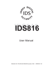
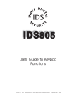
RMBE Series
Rack Mount Battery Enclosure
Operating and Installation Instructions
52-342 Rev A.01
Rack Mount Battery Enclosure Installation Instructions
5/27/2009, 11:42:41 AM
Warnings and Notices
WARNING - To reduce the risk of fire or electric shock, do not expose this product
to rain or moisture
WARNING - This installation and all servicing should be made by a qualified service
person and should conform to all local codes
NOTICE - This equipment shall be installed in a manner which prevents
unintentional operation from employees, janitors and cleaners working about the
premesis, by falling objects, by customers, by building vibration and by similar
causes
NOTICE - This equipment is not intended for use within the patient care areas of a
Health Care Facility
Symbol Definitions
m
WARNING - Read the instruction manual to avoid personal injury or
property damage
c
WARNING - Risk of electric shock. Service to be performed by a qualified
service person
52-342 Rev A.01
Page 2 of 14
AlarmSaf 65A Industrial Way, Wilmington, MA 01887 978 658 6717 www.alarmsaf.com
Rack Mount Battery Enclosure Installation Instructions
5/27/2009, 11:42:41 AM
Table of Contents
Section
I. Warnings and Notices
Page
2
1 Introduction
4
2 Applicable Standards / Documents
5
3 System Overview
3.1 Electrical Ratings and Specifications
3.2 Terminal Descriptions
5
5
6
4 Installation
4.1 Mounting
4.2 Wiring
7
7
9
5 Operating the RMBE Series
5.1 Jumper Configuration
5.2 Troubleshooting
10
10
11
6 Specifications
6.1 Electrical Specifications
6.2 Temperature Specifications
6.3 Mechanical Specifications
12
12
12
12
Appendices:
Glossary
14
52-342 Rev A.01
Page 3 of 14
AlarmSaf 65A Industrial Way, Wilmington, MA 01887 978 658 6717 www.alarmsaf.com
Rack Mount Battery Enclosure Installation Instructions
5/27/2009, 11:42:41 AM
Section 1
Introduction
The AlarmSaf RMBE Rack Mount Battery Enclosure provides one or two 12VDC or 24VDC battery outputs in a
standard 19” rack mountable enclosure. The enclosure contains two independent battery sets consisting of
two 7AH batteries each. The two sets can also be paralleled for a single battery set of increased capacity.
Designed as a companion product to the popular AlarmSaf RMDC series, but may also be used to provide
battery backup to panels, or any other rack mountable equipment requiring a 12VDC or 24VDC sealed
lead acid battery set.
Configuration is via pluggable jumpers on the back panel of the enclosure, allowing configuration without
opening unit
Contains two battery sets of two 7AH batteries (total of four 7AH batteries)
Each individual battery is protected by an internal self resetting PTC
Each battery set can be configured for either 12VDC or 24VDC
When set for the same voltage, the two battery sets can be paralleled for double the AH capacity
Multiple RMBE enclosures may be paralleled for additional amphour capacity
Pluggable output terminals feature locking screws
Unit is standard EIA rack mount size at 19” width and 3.5” (2RU) height - depth is 10”
Easy battery replacement
Configuration Capabilities:
Voltage
Battery Set 1 Battery Set 2
12V
12V
12V
12V
12V
24V
24V
12V
24V
24V
24V
24V
Output 1
Output 2
14AH@12V
14AH@12V
28AH @ 12V (Single Output)
14AH @ 12V
7AH @ 24V
7AH @ 24V
14AH @ 12V
7AH @ 24V
7AH @ 24V
14AH @ 12V (Single Output)
52-342 Rev A.01
Page 4 of 14
AlarmSaf 65A Industrial Way, Wilmington, MA 01887 978 658 6717 www.alarmsaf.com
Rack Mount Battery Enclosure Installation Instructions
5/27/2009, 11:42:41 AM
Section 2
Applicable Standards / Documents
NFPA Standards
NFPA 72 National Fire Alarm Code
NFPA 70 National Electrical Code
NFPA 731 Standard for the Installation of Electronic Premises Security Systems
Other
Applicable Local and State Building Codes
Requirements of the Local Authority Having Jurisdiction (LAHJ)
Section 3
System Overview
3.1 Electrical Ratings and Specifications
Manufactured By
AlarmSaf
65A Industrial Way
Wilmington, MA 01887
Tel:
800 987 1050
Tel:
978 658 6717
Fax:
978 658 8638
www.alarmsaf.com
Product Use
When installed in accordance with all standards listed in Section 2 of this document, the RMBE
battery enclosure provides single or dual battery backup for rack mount applications.
Model Number
RMBE-1224-4B7
Electrical Ratings
Voltage Batt Set 1
12V
12V
12V
24V
24V
24V
Voltage Batt Set 2
12V
12V
24V
12V
24V
24V
Parelleling
Jumper
Out
In
Out
Out
Out
In
Output 1
Output 2
14AH @ 12V
14AH @ 12V
28AH @ 12V (Single Output)
14AH @ 12V
7AH @ 24V
7AH @ 24V
14AH @ 12V
7AH @ 24V
7AH @ 24V
14AH @ 24V (Single Output)
52-342 Rev A.01
Page 5 of 14
AlarmSaf 65A Industrial Way, Wilmington, MA 01887 978 658 6717 www.alarmsaf.com
Rack Mount Battery Enclosure Installation Instructions
5/27/2009, 11:42:41 AM
3.2 Terminal Descriptions
All terminal strips are removable with locking screws and accept wire sizes from 12-26AWG. Wire
should be sized appropriately for voltage drop and current carrying capability. All terminals are
labeled for polarity where appropriate.
Battery Set 2 Configuration
Battery Set 1 Configuration
VOLTAGE SELECTION
IN-Parallel Set 1 and 2
OUT-Separates Set 1 and 2
24V
OR
The RMBE contains 2 battery sets which may be configured for:
12V / 12V - Two separate outputs; 24V / 24V Two separate outputs
12V and 24V - Two separate outputs
12V - One single output or 24V - One single output
VOLTAGE SELECTION
12V
24V
+ - + -
OR
12V
CAUTION - ONLY ONE VOLTAGE SELECTION PLUG + - + CAN BE INSTALLED TO EACH BAT SET
BATTERY
For complete information, read Installation
CONNECT
Instruction manual 52-342 or internal label.
BATTERY
CONNECT
Battery Set 2 Configuration
VOLTAGE SELECTION
IN-Parallel Set 1 and 2
OUT-Separates Set 1 and 2
24V
OR
The RMBE contains 2 battery sets which may be configured for:
12V / 12V - Two separate outputs; 24V / 24V Two separate outputs
12V and 24V - Two separate outputs
12V - One single output or 24V - One single output
12V
+ - + BATTERY
CONNECT
Fig 3.2.1
3.2.1 Battery Connect
Two outputs are provided for each battery set for connection to external equipment or other RMBE
enclosures.
Note - It is the responsibility of the installer to determine the minimum battery requirement for the
particular application in which the RMBE is being used. Backup batteries should be serviced at
regular intervals as determined by local and/or national codes.
52-342 Rev A.01
Page 6 of 14
AlarmSaf 65A Industrial Way, Wilmington, MA 01887 978 658 6717 www.alarmsaf.com
Rack Mount Battery Enclosure Installation Instructions
5/27/2009, 11:42:41 AM
Section 4
Installation
4.1 Mounting
4.1.1 Mount the unit in locations that meet the following temperature and humidity requirements.
Do not expose to conditions outside of these ranges.
Temperature
Humidity
0 °C to 49 °C (32 °F to 120 °F)
32 °C (90 °F) @ 93%
Mount the unit in a standard 19" equipment rack using the appropriate hardware for the rack.
CAUTION - A fully loaded RMBE can weigh more than 31 pounds, as installed. Care must be
taken when installing to prevent injury to the installer. Also, ensure that the rack into
which the RMBE is being installed can withstand the total weight of the equipment
installed. The RMBE should be installed near the bottom of the rack to ensure rack stability.
Install batteries into the RMBE enclosure (See Section 4.1.2)
Ensure all back panel jumpers are removed before installing into the rack
Locate an open 2RU slot in the rack and remove the filler panel(s), if present
Slide the unit into the open slot from the front of the rack
Install the four mounting screws into the end brackets of the unit
4.1.2 Installing or Replacing the Battery Set(s)
All batteries degrade with time and environment - periodic inspection and replacement is required.
Figure 4.1.2.1
52-342 Rev A.01
Page 7 of 14
AlarmSaf 65A Industrial Way, Wilmington, MA 01887 978 658 6717 www.alarmsaf.com
Rack Mount Battery Enclosure Installation Instructions
5/27/2009, 11:42:41 AM
1. Note the positions of the configuration jumpers on the back panel of the enclosure and
remove all jumpers. Remove any terminal strips with wiring connected.
2. If the enclosure is installed in a rack, remove the four mounting screws and carefully slide the
unit out of the rack.
3. Remove the six screws holding the enclosure’s top cover in place and remove the top cover.
4. Remove the four 6-32 nuts holding the battery clamp in place (see Figure 4.1.2.1) and remove
the battery clamp, taking care to not damage or disconnect any wiring.
5. If replacing existing batteries, carefully lift each battery, disconnect the fast-on connectors
from the battery, and remove the battery from the enclosure
NOTE - When replacing the batteries, ALL of the batteries in the enclosure should be
replaced at the same time. Ensure the new batteries are all of the same voltage and
AH capacity.
Figure 4.1.2.2
6. Connect and install new batteries, one at a time, as shown in F igure 4.1.2.2.
7. Carefully replace the battery clamp over the battery set. Route the wiring through the slots,
ensuring that no wiring is stressed, pinched, or disconnected.
8. Resecure the clamp with the four 6-32 nuts removed in Step 4.
9. Replace top cover and secure with the six screws removed in Step 3.
10. Carefully replace unit into rack as described in Section 4.1.1 and reconnect all terminal strips
and configuration jumpers.
52-342 Rev A.01
Page 8 of 14
AlarmSaf 65A Industrial Way, Wilmington, MA 01887 978 658 6717 www.alarmsaf.com
Rack Mount Battery Enclosure Installation Instructions
5/27/2009, 11:42:41 AM
4.2 Wiring
4.2.1 Wire Routing
All wiring must be installed in accordance with NFPA70 [NEC760] and all local code
requirements.
Power Limited wiring requires that power limited and nonpower limited wiring remain physically
separated. All power limited circuits must remain at least one quarter inch (¼") away from any
nonpower limited circuit wiring.
CAUTION - A lead-acid or gel cell battery can supply large amounts of current. Although
the RMBE has limiters on each battery, care should still be taken when wiring the RMBE to
prevent personal or property damage. Always remove the terminal st rips when wiring an
RMBE and ensure proper wiring before reconnection of the terminal strips.
Battery Set 2 Configuration
VOLTAGE SELECTION
IN-Parallel Set 1 and 2
OUT-Separates Set 1 and 2
24V
OR
The RMBE contains 2 battery sets which may be configured for:
12V / 12V - Two separate outputs; 24V / 24V Two separate outputs
12V and 24V - Two separate outputs
12V - One single output or 24V - One single output
12V
+ - + BATTERY
CONNECT
Figure 4.2.1
4.2.2 Battery Connection
Locate the terminal wiring blocks on the back panel of the unit and remove the terminal block
from the header (there are two locking screws, one on either end of the terminal block). Connect
the wiring to the terminal block. The back panel of the enclosure is labeled with the terminal and
polarity indications (See also Section 3.2). Replace the terminal block on the header and tighten
the locking screws.
NOTE - When the “Parallel Set 1 and 2” jumper is in place, both output terminal strips are
paralleled into a single battery set, and either terminal strip may be used.
4.2.3 Paralleling RMBE Enclosures for Increased AH capacity
Each battery set’s terminal strip has two separate pairs of output terminals. The extra pair of
terminals can be used to connect to an additional RMBE unit for increased amphour capacity.
Ensure correct polarity of wiring and correct setting of the configuration jumpers on ALL RMBE
enclosures before connecting two or more RMBE enclosures together.
52-342 Rev A.01
Page 9 of 14
AlarmSaf 65A Industrial Way, Wilmington, MA 01887 978 658 6717 www.alarmsaf.com
Rack Mount Battery Enclosure Installation Instructions
5/27/2009, 11:42:41 AM
Section 5
Operating the RMBE Series
5.1 Jumper Configuration
5.1.1 Configuration Jumper Settings
Before connecting the RMBE to a system, the configuration jumpers must be set for proper
operation. Do not change jumper settings while output wiring is connected to the system or
damage to the system may occur. The proper number of pluggable configuration jumpers are
provided with all RMBE enclosures. These jumpers are keyed and can only be installed in one
orientation.
Battery Set 2 Configuration
Battery Set 1 Configuration
VOLTAGE SELECTION
IN-Parallel Set 1 and 2
OUT-Separates Set 1 and 2
24V
OR
The RMBE contains 2 battery sets which may be configured for:
12V / 12V - Two separate outputs; 24V / 24V Two separate outputs
12V and 24V - Two separate outputs
12V - One single output or 24V - One single output
VOLTAGE SELECTION
12V
24V
+ - + -
OR
12V
CAUTION - ONLY ONE VOLTAGE SELECTION PLUG + - + CAN BE INSTALLED TO EACH BAT SET
BATTERY
For complete information, read Installation
CONNECT
Instruction manual 52-342 or internal label.
BATTERY
CONNECT
Fig 5.1.1
5.1.1.1 Voltage Selection Jumpers
For each battery set, only ONE voltage selection jumper must be in place. The back panel of
the RMBE is labelled for the voltage selection options. Each battery set may be configured
individually for 12VDC or 24VDC nominal.
NOTE - When the paralleling jumper is in place (See Section 5.1.1.2) BOTH voltage selection
jumpers MUST be set for the same voltage or damage to the system may occur.
5.1.1.2 Parallel Set 1 and 2 Jumper
When this jumper is in place, the two battery sets are paralleled internally to create one
battery set of double the AH capacity. Care must be taken to ensure both battery sets are
configured for the same voltage before installing this jumper (See Section 5.1.1.1).
5.1.1.3 Configuration Options for the RMBE Battery Enclosure
Voltage Batt Set 1
12V
12V
12V
24V
24V
24V
Voltage Batt Set 2
12V
12V
24V
12V
24V
24V
Parelleling
Jumper
Out
In
Out
Out
Out
In
Output 1
Output 2
14AH @ 12V
14AH @ 12V
28AH @ 12V (Single Output)
14AH @ 12V
7AH @ 24V
7AH @ 24V
14AH @ 12V
7AH @ 24V
7AH @ 24V
14AH @ 24V (Single Output)
52-342 Rev A.01
Page 10 of 14
AlarmSaf 65A Industrial Way, Wilmington, MA 01887 978 658 6717 www.alarmsaf.com
Rack Mount Battery Enclosure Installation Instructions
5/27/2009, 11:42:41 AM
5.2 Troubleshooting
WARNING - Installation and service should only be performed by a qualified service person and
should conform to all local codes
Condition
Possible Cause
Configuration jumpers missing
Tripped PTC(s)
No battery voltage present
Excessive loading
Internal wiring disconnected or
connected improperly
Discharged / Bad Battery
Incorrect configuration jumper setting
Excessive loading on output
The battery voltage is incorrect
Discharged / Bad Battery
External Charger not working
properly
Solution
Verify that the configuration jumpers
on the back panel are installed
appropriately (See Section 5)
Verify proper configuration jumper
settings and that there is not an
overcurrent condition, remove output
wiring or voltage selection jumper for
30 seconds, then replace the jumper.
See above
Ensure that all internal wiring of the
RMBE is connected properly.
Verify internal batteries are not
damaged and that they are charged replace if necessary.
Verify proper configuration jumper
setting
Verify that total output current is less
than rated current of RMBE
Verify internal batteries are not
damaged and that they are charged replace if necessary.
Verify that the equipment being used
to charge the RMBE is working
properly and is not overcharging or
undercharging the battery set.
52-342 Rev A.01
Page 11 of 14
AlarmSaf 65A Industrial Way, Wilmington, MA 01887 978 658 6717 www.alarmsaf.com
Rack Mount Battery Enclosure Installation Instructions
5/27/2009, 11:42:41 AM
Section 6
Specifications
6.1 Electrical Specifications
6.1.1 Output Voltage
6.1.2 Amphour Capacity
6.1.3 Overcurrent Protection
6.1.4 Maximum Operating Current
12VDC or 24VDC Nominal
Varies - See Section 5.1.1.3
9A at 24V, 18A at 12V per battery set
8 amperes
6.2 Temperature Specifications
6.2.1 Ambient Temperature Range
6.2.2 Ambient Humidity
6.2.3 BTU Output
0ºC to 49ºC (32ºF to 120ºF)
93% at 32ºC (90ºF) maximum
Not Applicable
6.3 Mechanical Specifications
6.3.1 Weight
Approx. 30 lbs.
6.3.2 Overall Size
19.00”W x 10.75”D x 3.50”H
Note: Depth includes terminal
strips on back panel
52-342 Rev A.01
Page 12 of 14
AlarmSaf 65A Industrial Way, Wilmington, MA 01887 978 658 6717 www.alarmsaf.com
Rack Mount Battery Enclosure Installation Instructions
5/27/2009, 11:42:41 AM
9.940"
3.250"
6.3.3 CAD Drawing
18.880"
1.203"
1.202"
16.87"
0.75"
0.815"
3.71"
3.249"
0.683"
0.752"
0.375"
DETAIL “A”
TYPICAL 4 PLCS
.25"
0.375"
Ø .1875”
Ø .1875”
DETAIL “ A “
52-342 Rev A.01
Page 13 of 14
AlarmSaf 65A Industrial Way, Wilmington, MA 01887 978 658 6717 www.alarmsaf.com
Glossary
5/27/2009, 11:42:41 AM
Glossary
ABC
See “Accessory Board Connector”
Accessory Board Connector
Connector present on some AlarmSaf power supplies and accessory boards, allowing plug-in
expansion of the system
Accessory Board
An AlarmSaf product for use with AlarmSaf power supplies containing an ABC connector.
These boards allow plug-in expansion of the functionality of the system. Examples of
accessory boards include, but are not limited to, voltage distribution (simple and controlled),
secondary DC-DC power supplies, and NAC Circuit expanders.
AC-DC Converter
A DC power supply whose voltage input is either direct from the AC line or though a
step-down AC transformer
Buss 1 (B1)
The primary DC voltage in a system. Typically the higher of the two voltages in dual voltage
systems
Buss 2 (B2)
The secondary DC voltage in a system. Only dual voltage systems use this voltage.
Class 2 Power Limited
A voltage output or wiring which conforms to NEC Article 725.
Controlled Distribution
Voltage distribution providing on/off control for the outputs. Control can be from FAI, an
access control panel, card reader, or other device. The MB8(F) and CMB8(F) accessory
boards, and the APD8(F) are examples of controlled distibution.
DC-DC Converter
A DC power supply whose voltage input comes from another DC source. DC-DC converters
allow multi-voltage system backup with a single battery set.
FAI
See “Fire Alarm Interface”
Fire Alarm Interface
Input present on some AlarmSaf products allowing control of output(s) in the system.
Typically used for dropping power to maglocks on egress doors during a fire alarm
condition, but can also be used for other control functions, such as resetting smoke
detectors
Power Limited
A voltage output or wiring which conforms to NEC Article 725.
PTC
A resettable overcurrent protection device, similar to a fuse or circuit breaker.
Rack Mount
A product which has an enclosure that allows mounting in a standard 19 inch equipment
rack
Simple Distribution
Voltage distribution without any control function for the distributed outputs. Power is
always available to the outputs. The PD8(F) accessory board is an example of simple
distribution.
Voltage Distribution
Splitting a bulk power supply output into multiple, current limited outputs to prevent a
single circuit failure from talking down an entire system. The multiple terminal outputs also
simplify wiring by providing a pair of terminals for each circuit, rather than wiring several
circuits to a single pair of terminals.
Glossary Rev A.01
Page 14 of 14
AlarmSaf 65A Industrial Way, Wilmington, MA 01887 978 658 6717 www.alarmsaf.com