1
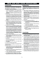
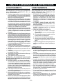
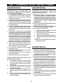
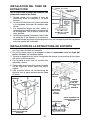
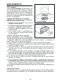
INSTALL THE DUCTWORK
ROOF CAP
NOTE: To reduce the risk of fire, use only
metal ductwork.
1.Decide where the ductwork will run between
the hood and the outside.
2. A straight, short duct run will allow the hood
to perform most efficiently.
3. Long duct runs, elbows, and transitions will
reduce the performance of the hood. Use as
few of them as possible.
4. Install a roof or wall cap. Connect 6" round
metal ductwork to cap and work back towards hood location. Use duct tape to seal
the joints between ductwork sections.
6” ROUND DUCT
6” ROUND
ELBOW
HOOD
DECORATIVE
FLUE
EAVE
VENT
24” TO 30” ABOVE
COOKING SURFACE
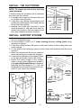
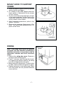
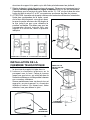
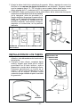
INSTALL SUPPORT SYSTEM
1. Assemble the upper half of support frame to the upper plate and fix it by means of
the four supplied screws.
2. At hood location, install 2 X 4 cross framing between ceiling joists using
dimensions shown.
3. Finish the ceiling surface. Be sure to mark the location of the ceiling joists and
cross framing.
4. Fix the plate to the ceiling by means of the screws with washers and the screw
anchors.
5. Make sure screws are driven into center of
joists and framing for maximum strength.
CROSS
9-27/32”
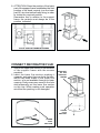
6. Connect the lower part of the support frame
FRAMING
to the part previously fixed to the ceiling.
7. Adjust the overall height of the support
frame. Loosen and re-tighten the screws in
the height adjustment slots as necessary.
Note that the hood height is 13 - 3/8” and
that the bottom of the hood must be 24” min.
CEILING
and 30” max. above the cooktop.
JOISTS
UPPER
HALF OF
SUPPORT
FRAME
UPPER
PLATE
HEIGHT
ADJUSTMENT
SLOTS
CROSS
FRAMING
9
UPPER
HALF OF
SUPPORT
FRAME
”
27/32”
751/64”
-4-
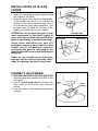
TOP VIEW
OF
SUPPORT
FRAME