1
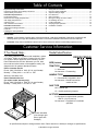
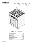
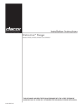
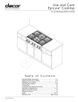
Installation Instructions
Distinctive ™ 30 - Inch Gas Range
For use with models DR30GS, DR30GFS, DR30GIS and DR30GIFS
THIS APPLIANCE HAS BEEN TESTED IN ACCORDANCE WITH THE LATEST EDITION
OF ANSI Z21.1a-2011 STANDARD FOR HOUSEHOLD GAS COOKING APPLIANCES.
Part No. 105908 Rev. A
Table of Contents
Important Safety Instructions...................................................... 1
Important Information About Safety Instructions.............................1
General Safety Precautions............................................................ 2
Installation Specifications............................................................4
Product Dimensions........................................................................4
Electrical Power Supply Requirements...........................................5
Gas Supply Requirements.............................................................. 5
Cabinet Layout................................................................................6
Gas and Electrical Locations........................................................... 8
Installation Instructions................................................................8
Verifying the Package Contents...................................................... 8
Parts List.........................................................................................8
Installing the Anti-Tip Bracket.......................................................... 8
Backguard Kit Installation.............................................................. 10
Rear Trim Piece Installation.......................................................... 10
Adjust the Range Height............................................................... 11
Door Removal............................................................................... 11
Gas Connection.............................................................................12
Moving the Range to Final Location.............................................13
Re-Installing the Door................................................................... 13
Cooktop Assembly.........................................................................14
Verifying Proper Operation............................................................ 15
Installation Checklist......................................................................16
IMPORTANT:
•
Installer: In the interest of safety and to minimize problems, read these installation instructions completely and
carefully before you begin the installation process. Leave these installation instructions with the customer.
•
Customer: Keep these installation instructions for future reference and the local building inspector’s use.
Customer Service Information
If You Need Help...
Model Identification
If you have questions or problems with installation, contact
your Dacor ® dealer or the Dacor Customer Service Team.
For repairs to Dacor appliances under warranty, call the
Dacor Distinctive Service line. Whenever you call, have
the model and serial number of the appliance ready. See
diagram below for product data label location.
Dacor Customer Service
Phone: (800) 793-0093 ex. 2813 (U.S.A. and Canada)
Monday — Friday 6:00 a.m. to 5:00 p.m. PST
I = Island trim
No character = Freestanding
Web site: www.dacor.com
Dacor Distinctive Service
(for repairs under warranty only)
Phone: (800) 793-0093 ex. 2822 (U.S.A. and Canada)
Monday — Friday 6:00 a.m. to 5:00 p.m. PST
DR30G I FS/NG/H
SIZE (inches)
TRIM TYPE
HANDLE TYPE
F = Flush handle, integrated in door
No character = Handle mounted on
outside of door
GAS TYPE
NG = Natural gas
LP = Liquid petroleum (propane)
ALTITUDE
H = Equipped for high altitude operation,
4000 ft. (1219 m) and up
No character = Equipped for low altitude
operation
Product data label
(view through right
side of grate with
flashlight)
All specifications subject to change without notice. Dacor assumes no liability for changes to specifications.
© 2012 Dacor, all rights reserved.
Important Safety Instructions
Important Information About Safety
Instructions
The Important Safety Instructions and warnings in this
manual are not meant to cover all possible problems and
conditions that can occur. Use common sense and caution
when installing, maintaining or operating this appliance.
Always contact the Dacor Customer Service Team about
problems or conditions you do not understand.
Safety Symbols and Labels
DANGER
Immediate hazards that WILL result in severe personal
injury or death.
WARNING
Hazards or unsafe practices that COULD result in severe
personal injury or death.
WARNING
Hazards or unsafe practices that COULD result in minor
personal injury or property damage.
WARNING
WARNING: If the information in this manual is not
followed exactly, a fire or explosion may result
causing property damage, personal injury or death.
–– Do not store or use gasoline or other flammable
vapors and liquids in the vicinity of this or any other
appliance. Also keep items that could explode, such
as aerosol cans, away from the burners and the
oven. Do not store flammable or explosive materials
in adjacent cabinets or areas.
WARNING
WARNING – NEVER use this appliance as a space
heater to heat or warm the room. Doing so may result
in carbon monoxide poisoning and overheating of the
appliance.
WARNING
WARNING – NEVER cover any slots, holes or passages
on the inside or outside of the range or cover an entire
rack with materials such as aluminum foil. Doing so
blocks air flow through the oven and may cause carbon
monoxide poisoning. Aluminum foil linings may also trap
heat, causing a fire hazard.
WARNING
Tip-over hazard:
• A child or adult can tip the range and be killed.
• Attach the anti-tip bracket to the floor or wall as
directed in these installation instructions.
• Engage the floor or wall mounted anti-tip bracket by
sliding the rear leg on the range into it according to
these installation instructions. Using a flashlight, be
sure that the anti-tip bracket engages the range’s rear
leg as shown below.
• After moving the range, be sure to re-engage the rear
leg into the anti-tip bracket as shown below.
• See the anti-tip bracket installation instructions in this
guide for further details.
• Failure to follow these instructions can result in death
or serious burns to children or adults.
–– WHAT TO DO IF YOU SMELL GAS
•
•
•
•
Do not try to light any appliance.
Do not touch any electrical switch.
Do not use any phone in your building.
Immediately call your gas supplier from a
neighbor’s phone. Follow the gas supplier’s
instructions.
• If you cannot reach your gas supplier, call the fire
department.
–– Installation and service must be performed by a
qualified installer, service agency or the gas supplier.
Anti-tip
bracket
Rear leg
READ AND SAVE THESE INSTRUCTIONS
1
Important Safety Instructions
General Safety Precautions
To reduce the risk of fire, explosion, electric shock, serious injury or death when installing or using this appliance, follow
basic safety precautions, including the following:
WARNING
•
Read the accompanying use and care manual
completely before operating this appliance.
•
Keep packaging materials away from children.
Plastic sheets and bags can cause suffocation.
•
If you receive a damaged product, immediately
contact your dealer or builder. Do not install or use a
damaged appliance.
•
•
Do not leave children or pets alone or unattended
in the area around the range. Do not allow children
to play with the controls, pull on the handle or touch
other parts of the range.
•
Do not store items of interest to children on top of or
above the range. Children could be burned or injured
while climbing on the appliance.
This range must be properly installed by a qualified
installer according to these installation instructions
prior to use. The installer should show the customer
the location of the gas shut off valve and the fuse
or junction box so that they know where and how
to turn off the gas supply and electric power to the
range.
•
Do not attempt to use this appliance in the event of a
power failure.
•
Do not tamper with the controls. Do not adjust
or alter any part of the range unless specifically
instructed to do so in these instructions.
•
•
Do not operate the range without the backguard in
place. A fire may result.
Clean the cooktop thoroughly before operating it for
the first time.
•
•
Do not install, repair or replace any part of the range
unless specifically recommended in the literature
accompanying it. A qualified service technician
should perform all other service.
Keep flammable items, such as paper, cardboard,
plastic and cloth away from the burners and other
hot surfaces. Do not place such items in the oven.
Do not allow pot holders to touch hot surfaces or gas
burners.
•
Do not connect this range to the gas supply without
the supplied gas pressure regulator installed.
•
•
Before performing any type of service or installation,
make sure that the gas supply and power to the
range are off.
Do not wear loose or hanging apparel while using
the range. Do not allow clothing to come into contact
with the interior of the oven or the cooktop and
surrounding areas during and immediately after use.
•
To avoid a fire hazard, do not hang flammable or
heat sensitive objects over the range.
•
NEVER block or cover any slots, holes or passages
anywhere inside the oven or on the outside of the
range or cover an oven rack with materials such as
aluminum foil. Doing so blocks airflow through the
oven and cooktop and may cause carbon monoxide
poisoning or fire. See the Getting to Know Your
Range section of the use and care manual for the
location of the various air holes (slots).
•
If the range is near a window, do not use long
curtains as window treatment. The curtains could
blow over the cooktop and create a fire hazard.
•
Do not use the oven for storage.
•
Make sure that all the cooktop parts are dry before
lighting a burner.
•
Turn the knobs to the OFF position prior to removing
them from the valve stems.
•
For your safety, do not use the oven to cook without
the convection filter installed. When the filter is not
installed, the spinning fan blades at the back of the
oven are exposed.
•
Do not operate the cooktop without the knobs and
trim rings in place.
•
Non-stick coatings, when heated, can be harmful to
birds. Remove birds to a separate, well-ventilated
room during cooking.
•
•
2
WARNING
To avoid risk of fire, do not cover the broil element on
the ceiling of the oven with cookie sheets, aluminum
foil, pots, pans, etc.
Only use this range for cooking tasks expected
of a home appliance as outlined in the literature
accompanying it. This range is not intended for
commercial use.
•
DO NOT TOUCH THE SURFACES OF THE OVEN
OR COOKTOP DURING OR IMMEDIATELY AFTER
USE.
•
Do not climb on any part of the appliance.
•
Never leave this appliance unattended when in use.
Important Safety Instructions
WARNING
WARNING
•
Do not expose the knobs to direct flame, hot utensils
or other sources of heat.
TO REDUCE THE RISK OF INJURY TO PERSONS IN
THE EVENT OF A RANGE TOP GREASE FIRE:
•
Always ensure that the light fixture lens cover is in
place when using the oven. The lens cover protects
the light bulb from breakage caused by high oven
temperatures or mechanical shock.
a. SMOTHER FLAMES with a close-fitting lid, cookie
sheet or metal tray, then turn off the burner. BE
CAREFUL TO PREVENT BURNS. If the flames do not
go out immediately, EVACUATE AND CALL THE FIRE
DEPARTMENT.
b. NEVER PICK UP A FLAMING PAN - you may be
burned.
c. DO NOT USE WATER, including wet dish cloths or
towels - a violent steam explosion may result.
d. Use a fire extinguisher ONLY if:
◊ You have a Class ABC extinguisher, and you
already know how to operate it.
◊ The fire is small and contained in the area where it
started.
◊ The fire department is being called.
◊ You can fight the fire with your back to an exit.
IMPORTANT - This appliance is equipped with a
three-prong grounding plug for your protection
against possible electric shock hazards. Plug it only
into a dedicated, grounded three-prong electrical
outlet. It is the responsibility of the customer to
make sure the proper type of outlet is installed. Do
not under any circumstances:
•
Cut or remove the third (ground) prong from the
power cord.
•
Use an adapter plug.
•
Use an extension cord.
•
Use a power cord that is
frayed or damaged.
•
Connect to an electrical
outlet with a ground fault
interrupter (GFI).
CALIFORNIA
PROPOSITION 65 WARNING
The burning of gas cooking fuel generates some
by-products that are on the list of substances which
are known by the State of California to cause cancer or
reproductive harm. California law requires businesses
to warn customers of potential exposure to such
substances. To minimize exposure to these substances,
always operate this unit according to the use and care
manual, ensuring you provide good ventilation when
cooking with gas.
3
Installation Specifications
Product Dimensions
All tolerances: ±1/16” (±1.6 mm), unless otherwise stated
Front of open door
Front of knobs
45 9/16” (115.7 cm)
28 9/16” (72.5 cm)
26 1/8” (66.4 cm)
24” (61.0 cm)
Front panel
Rear of front panel
1 1/8” (2.9 cm)
Backguard thickness
9” (22.9 cm)
Grates extend Backguard*
1” above trim
3” (7.6 cm)
backguard*
DR30GI[F]S:
1/4” (6.4 mm)
DR30G[F]S:
Full stainless
steel side panels
External handle
shown, some models
have integral handle
(see inside cover)
Product width:
29 7/8” (75.9 cm)
DR30GI[F]S:
3 1/4” (8.3 cm)
partial stainless
steel side panels
(removable)
NOTE: Neither version is
compatible with a raised vent.
6” (15.2 cm)
backguard*
1 3/4” (4.4 cm) backguard*
* See table for compatibility
35”
(88.9 cm)
to
37”
(94.0 cm)
Overall Dimensions - Side View
Available Backguards
4
Part Number
Description
Compatibility
AER30GLBG
Low profile
(1 3/4 inch)
AERB30G03
3 Inch
Optional on models DR30GS, DR30GFS
NOT compatible with models DR30GIS, DR30GIFS
AERB30G06
6 Inch
Standard on models DR30GS, DR30GFS
NOT compatible with models DR30GIS, DR30GIFS
AERB30G09
9 Inch
Optional on models DR30GS, DR30GFS
NOT compatible with models DR30GIS, DR30GIFS
Standard on models DR30GIS, DR30GIFS
Optional on models DR30GS, DR30GFS
Installation Specifications
WARNING
• This appliance must be installed and electrically
grounded in conformance to local codes.
• In the absence of local codes, the appliance
installation must conform with the National Fuel
Gas Code, ANSI Z223.1/NFPA 54 and the National
Electrical Code, ANSI/NFPA 70.
• Installation of this range in a manufactured (mobile)
home must conform with the Manufactured Home
Construction and Safety Standard, Title 24 CFR, Part
3280 [formerly the Federal Standard for Mobile Home
Construction and Safety, Title 24, HUD (Part 280)] or
with local codes where applicable.
• This range is not designed for installation in a
recreational vehicle.
• Do not obstruct flow of combustion and ventilation air.
• To prevent an electric shock hazard, the power supply
must meet the specifications stated below. It is the
owner’s responsibility to make sure that the electrical
service meets electrical requirements and that the
electrical outlet has been properly installed by a
licensed electrician.
Electrical Power Supply Requirements
•
•
The range is supplied with a factory installed, 6 foot
long, power cord with a three-prong grounding plug.
It is connected to the chassis at the rear of the range.
It must be connected to a dedicated, grounded threeprong electrical outlet installed by a licensed electrician.
The correct voltage, frequency and amperage must
be supplied to the electrical outlet according to the
product data label (see inside cover for location). The
Electrical Supply Requirements provided below are
for reference.
Electrical Circuit
Required
Total Connected Load
120 Vac 60 Hz,
15 Amp.
0.5 kW
(4.0 Amp.)
Gas Supply Requirements
•
Be certain that the range being installed is correct for
the gas service being provided (natural gas or LP gas).
•
An external manual shut-off valve must be installed
between the gas inlet and the range for the purpose of
turning on or shutting off gas to the appliance.
•
The range comes from the factory with the regulator
installed. Use only the installed regulator.
•
The gas inlet on the regulator accommodates a
1/2” NPT gas line connection. The range can also
accommodate a 3/4” NPT gas line connection by
removing the 1/2” to 3/4” adapter on the regulator inlet.
Gas
Type
Manifold
Pressure*
(WC)
Min. Gas Supply
Pressure (WC)
Max. Input
Pressure
Natural
5”
6”
1/2 psi
LP
10”
11”
1/2 psi
Gas Supply Requirements
* The gas supply pressure for testing the regulator setting
shall be at least 1 inch water column (249 Pa) above the
specified manifold pressure.
IMPORTANT: The information above is for reference only. If
the above data does not agree with the product data label,
use the data on the label. See the inside cover for location.
The gas connection is located on the back of the unit as
shown below.
12 1/4”
(31.1 cm)
to
14 1/4”
(36.2 cm)
Gas
connection
Power
cord
Electrical Supply Requirements
IMPORTANT: The above information is for reference only.
If the information above differs from the information on the
product data label on the appliance, use the information on
the label.
4 1/4”
(10.8 cm)
5
Installation Specifications
Cabinet Layout
WARNING
All tolerances: +1/16” (+1.6 mm), -0
unless otherwise stated
• Failure to meet or exceed the maximum
and minimum dimensions/clearances stated
may result in a fire hazard.
• To eliminate the risk of burns or fire by
reaching over heated surface units, cabinet
storage space located above surface units
should be avoided.
B
13” (33.0 cm)
max.4
Back wall
immediately
behind range6
•
Carefully check the location where the range
is to be installed. For best performance, the
range should be placed away from drafts
that may be caused by doors, windows and
heating and air conditioning outlets.
•
To reduce the risk of personal injury and
to reduce accumulated smoke in the room,
Dacor strongly recommends installing
a range hood. A range hood should
project horizontally a minimum of five (5)
inches beyond the face of the cabinets. If
installing a range hood, see the range hood
specifications for minimum clearances.
•
If cabinet storage space is to be provided
directly above the range, the risk of personal
injury may be reduced by installing a range
hood.
•
The range may be installed flush to the rear
wall. See diagram and notes for rear wall
surface requirements. It is not necessary to
install non-combustible materials behind the
range below the countertop height.
•
Regardless of the type of back wall surface,
the range must not be installed or operated
without the backguard in place.
•
Any openings in the wall behind the
appliance or in the floor underneath it must
be sealed.
Top of
finished
counter
Note 1
Note 5
A
14” (35.6 cm)
min.4
Suggested
location of
utilities3
Note 2
C
A*
B
C
30”
minimum
(76.2 cm)
36” (91.4 cm)
recommended
30” (76.2 cm)
minimum
37”
(94.0 cm)
maximum
*See cutout dimensions on facing page for
self-rimming installations.
Freestanding Installation Cabinet Cutout Dimensions - Models DR30GS, DR30GFS, DR30GIS and DR30GIFS
1 30” (76.2 cm) min. vertical clearance from top of range grates to bottom of uncovered wood or metal cabinet. 24” (61 cm) min.
clearance if bottom of wood or metal cabinets are protected by not less than 1/4“ (0.6 cm) flame retardant millboard covered with no
less than No. 28 MSG sheet steel 0.015” (0.04 cm) stainless steel, or 0.024” (0.06 cm) aluminum or 0.020” (0.05cm) copper. 30”
(76.2 cm) min. clearance between top of range grates and bottom of unprotected wood or metal cabinet. If installing range hood, check
the hood specifications for minimum required clearances.
2 Cabinet/countertop depth is at discretion of customer but cabinet face SHALL NOT protrude further than rear of front panel. See
Product Dimensions.
3 Consult local code and page 8 for requirements.
4 This specification not applicable for cabinets more than a horizontal distance of 10” (25.4 cm) from edge of range.
5 10” (25.4 cm) min. to combustible sidewalls above range (both sides).
6 Non-combustible surface required for models DR30GIS and DR30GIFS up to vertical distance specified in note 1 or range hood,
whichever is lower. Non-combustible surface recommended, but not required, for models DR30GS and DR30GFS.
6
Installation Specifications
Self-Rimming Installation Cutout Options (Models DR30GIS and DR30GIFS Only)
For all self-rimming installations:
Countertop height: 34 3/4” (88.3 cm) min. 36 7/8” (93.7 cm) max.
Countertop thickness: 1 5/8” (4.1 cm) max.
10” min. (25.4 cm)
to any combustibles
above counter both sides
10” min. (25.4 cm)
Rear wall*or
3/4” min. (1.9 cm)
to any combustibles
countertop edge countertop overhang
above counter both sides
Non-combustible
rear wall required *
25 5/8”
max.
(65.1 cm)
29 1/4” (74.3 cm)
countertop opening
30” (76.2 cm)
cabinet opening
below countertop
Notch countertop
to width of cabinets
Cabinet face
Countertop front below countertop
21”
20 3/4” (53.3 cm)
to
(52.7 cm)
24”
(61.0 cm)
Cabinets Less Than 24” Deep,
3 1/4” Side Panels Installed, Range Back Flush to Wall
(Top View)
10” min. (25.4 cm)
to any combustibles
above counter both sides
29 1/4” (74.3 cm)
countertop opening
30” (76.2 cm) ***
cabinet opening
below countertop
Cabinet face
below countertop
Notch countertop
overhang to width of
cabinets
Non-combustible
rear wall required *
24”
(61.0 cm)
Countertop overhang
1 5/8” (4.1 cm) max.
Cabinet Exactly 24” Deep,
3 1/4” Side Panels Removed, Range Back Flush to Wall
(Top View)
25 3/4”
(65.4 cm)
max.
29 1/4” (74.3 cm)
countertop opening
30” (76.2 cm)
cabinet opening
below countertop
Notch countertop
to width of cabinets
Cabinet face
Countertop front below countertop
21 1/8”
20 7/8” (53.7 cm)
to
(53.0 cm)
24 1/8”
(61.3 cm)
Cabinet Depth Greater Than 24” **
3 1/4” Side Panels Installed, Range Back Overhanging
Countertop (Top View)
10” min. (25.4 cm)
Rear wall *or
to any combustibles
countertop edge
above counter both sides
29 1/4” (74.3 cm)
countertop opening
30” (76.2 cm) ***
cabinet opening
below countertop
Cabinet face
below countertop
Notch countertop
overhang to width of
cabinets
3/4” min. (1.9 cm)
Countertop overhang
24 1/8”
(61.3 cm)
Countertop overhang
1 5/8” (4.1 cm) max.
Cabinet Depth Greater Than 24” **
3 1/4” Side Panels Removed, Range Back Overhanging
Countertop (Top View)
* On models DR30GIS and DR30GIS, non-combustible surface required immediately behind range, as specified on facing page, when
back of backguard is less than 2 1/2” (6.4 cm) from rear wall.
** Models DR30GIS and DR30GIS include self-rimming trim piece that attaches to back of range and covers the edge of the countertop
overhang in back.
*** To create a “built-in look” on the front of the cabinet, this dimension may be changed to 29 1/4” (74.3 cm), with the width at the
notches remaining 30”. This configuration is only for models DR30GIS and DR30GIS with side panels behind door removed.
7
Installation Specifications
Gas and Electrical Locations
•
•
Dacor recommends that utility access for all models
be installed in an adjacent cabinet, as shown on page
6. If the utilities are installed behind the range, the
installation must allow for the following:
CL
10” (25.4 cm)
10” (25.4 cm)
◊
•
Access to the gas shut-off valve when the unit is
installed.
◊ Access to the electrical outlet, when the range is in
place.
◊ The gas supply piping, gas shut-off valve and the
electrical outlet must be located so they do not
interfere with the range when it is installed.
◊ The electrical outlet and gas shut off valve must
be located so that the range can be pulled out for
service while the appliance remains connected.
Both the gas supply piping and shut-off valve and the
electrical outlet must be located so they do not interfere
with the range when it is installed.
Existing utility connections may be used for
replacement purposes, provided they meet local code
and fit within the utility clearance area at the back of
the range. See diagram, below.
12” (30.5 cm)
2 1/2”
(6.4 cm)
1” (2.5 cm)
3 1/2” CL
Utility
(8.9 cm)
Clearance
Behind Range
Installation Instructions
WARNING
•
•
If the gas or electric service provided does not meet
the product specifications, do not proceed with the
installation. Call the selling dealer, the gas supplier or
a licensed electrician.
This appliance must be installed by a licensed
plumber or gas fitter when installed within the
Commonwealth of Massachusetts.
Verifying the Package Contents
Unpack the range and verify that all required parts have
been provided. If any item is missing or damaged, please
contact your dealer immediately. Do not install a damaged
or incomplete appliance. The customer must report
cosmetic issues immediately to the dealer or builder.
Parts List
•
Anti-tip bracket with screws and anchors
•
2 grates
•
Use and care manual
•
Stainless steel cleaner
•
1 dual burner ring
•
1 outer dual burner cap
•
1 inner dual burner cap
•
3 standard burner caps (2 large, 1 small)
•
3 standard burner rings (2 large, 1 small)
•
2 oven racks
•
Rear self-rimming trim piece (DR30GIS/DR30GIFS only)
•
2 #8 x 1/4 Torx screws (DR30GIS/DR30GIFS only only)
8
Installing the Anti-Tip Bracket
Locate the anti-tip bracket included in the parts box.
There are two ways to mount the anti-tip bracket:
•
Floor mounting (preferred method)
•
Wall mounting (alternate method). Use this method if
floor mounting is not suitable. If any of the conditions
below exist, then the wall mounting method can not be
used and the floor mounting method must be suitable.
The anti-tip bracket may not be mounted to the wall if:
◊ The wall contains metal stud mounting materials that
interfere with the anti-tip bracket mounting screws.
◊ The front panel of range is further than the maximum
distances from the back wall stated on page 10.
◊ The flooring is too thick (see Installing the Anti-Tip
Bracket on the Wall).
Installing the Anti-Tip Bracket on the Floor.
WARNING
To perform its intended function, the anti-tip bracket
must be attached as instructed to the concrete slab
or wood sub-floor below any floor coverings (including
cement board) on top. Do not attach the anti-tip bracket
directly to floor coverings such as ceramic/asphalt tile or
linoleum.
Installation Instructions
Four (4) plastic anchors are provided along with three sizes
(4 each) of #8 or #12 Phillips head screws for attaching
the anti-tip bracket to the floor. Use both the anchors and
four (4) of the #8 screws when attaching the bracket to a
concrete sub-floor. Do not use the anchors when attaching
to a wood sub-floor.
Side View
Attaching the bracket to a concrete floor:
•
Drill four (4) 3/8” diameter countersink holes through
any existing floor covering to the concrete slab below.
•
Drill the 4 holes for the anchors 1 1/4” (3.2 cm) deep
into the concrete slab using a 3/16” masonry bit. This
hole length is longer than the anchor, but is required
for proper installation. Clear the holes of dust and any
other material. Tap each anchor into the hole until the
anchor top is flush with the top of the concrete slab.
Position the anti-tip bracket holes over the anchor
holes. Insert the screws through the four (4) holes
in the base of the bracket and thread them into the
anchors. Be sure the screw threads fully engage the
anchor body. Tighten the screws into place.
Anti-tip
bracket
Floor
covering
Concrete
anchors shown,
do not use for
wood sub-floor
Sub-floor
Screws attached
to sub-floor below
floor covering
1. Determine the location of the range center line and
front panel when the range is in its final position
based on the Product Dimensions on page 4
and the actual cabinet/cutout dimensions used for the
installation.
Attaching the bracket to a wood floor:
•
If there is ceramic, asphalt or other hard floor covering
over the wood below, drill four (4) countersink holes to
allow access to the wood below for drilling pilot holes.
•
Drill four (4) pilot holes into the wood floor using a drill
bit (1/16” dia. for #8 screws, 1/8” dia. for #12 screws).
Position the anti-tip bracket holes over the holes in the
floor. Insert the screws into the wood and tighten into
place.
2. Determine the required position of the anti-tip bracket,
based on the diagram, bottom right. Mark the four (4)
mounting hole locations on the floor with a pencil.
#8 x 1”, #8 x 1 1/4”
or #12 x 1 3/4
screw, 4 places
(see text)
3. Determine the screw size required. The minimum full
thread depth (portion of screw threaded into wood/slab)
for wood is 3/8” (1 cm) and 5/8” (1.6 cm) for concrete.
See the table below to select the correct screw size.
Screw Size
Concrete or wood sub-floor, no
floor covering over top.
#8 x 1 *
Concrete or wood sub-floor, floor
covering up to 1/4” thick
#8 x 1 *
Concrete or wood sub-floor, floor
covering over 1/4” and up to 1/2”
thick
#8 x 1 1/4 *
Wood sub-floor, floor covering
over 1/2” and up to 1 3/16” thick
#12 x 1 3/4 *
Concrete sub-floor under floor
covering over 1/2” thick
Must be purchased
separately **
Wood sub-floor, floor covering
over 1 3/16” thick
Must be purchased
separately **
* Included with range
** Determine required depth based on information in step 3
and purchase from local hardware store.
Front hole
Anchor, 4 places:
use for concrete
floor only
Top View
Anti-tip bracket
front hole
locations
Cabinet
face below
countertop
22 1/2”
(57.2 cm)
Sub-Floor Type/
Floor Covering Thickness
CL
2 3/16” (5.6 cm)
Range front
panel
Range center line
10 3/8” (26.4 cm)
9
Installation Instructions
Installing the Anti-Tip Bracket on the Wall
1. Determine the suitability of wall mounting the anti-tip
bracket. To use the wall mount option, the range front
panel must not be more than 27 3/8” (69.5 cm) from
the wall and the bracket screws must be able to thread
into the base plate inside the wall behind. The notches
on the sides of the bracket indicate the minimum
required height of the base plate inside the wall and
that any floor covering is not too thick for proper screw
thread engagement.
Top hole, indicates
bracket center line
#12 x 1 3/4”
screw,
4 places
Back wall
To determine if the base plate is high enough:
a. Determine the location of the range center line
and front panel when the range is in its final
position based on the Product Dimensions
on page 4 and the actual cabinet/cutout
dimensions used for the installation.
Anti-tip
bracket
Drywall
Bracket
center line
Cabinet
face below
countertop
Notch
Wall
Base
plate
Side View
b. Determine and mark the required position of the
anti-tip bracket, based on the diagram above.
Push the bracket up against the wall in the
mounting location.
c. Using a pencil, make a dot next to the notches
on both sides of the bracket. Determine if the
base plate is as high at the notches by drilling
test holes into the wall at both dots with a 1/16”
drill bit. Drill just deep enough to see if the
bit contacts the base plate. If the bit contacts
the base plate the location will support wall
installation of the anti-tip bracket. If you do not
contact the base plate, or you contact metal stud
mounting materials, the wall mounting method
may not be used and the floor mounting method
must be suitable, or the wall must be modified so
that the base plate is above the notches.
4. To install the bracket, place it against the wall in the
mounting location shown in the diagram, upper right.
Using a drill with 1/8” diameter drill bit, drill four (4) 1
5/8” deep pilot holes perpendicular to the screw seating
surfaces shown, above right. Attach the bracket to the
wall as shown with the four (4) included #12 x 1 3/4
screws.
10
Range
front panel
CL CL
26 1/8”
(66.4 cm)
to
27 3/8”
(69.5 cm)
Range
center line
11 1/2” (29.2 cm)
Anti-Tip Bracket - Wall Installation - Top View
Backguard Kit Installation
See page 4 for available part numbers and
compatibility.
If installing a backguard other than the standard size,
install it before pushing the range into place. Install the kit
according to the accompanying installation instructions. A
T-20 Torx driver is required.
Rear Trim Piece Installation
(Model DR30GIS/DR30GIFS only)
To cover a countertop overhang in back, install the rear trim
piece on the back side of the backguard. Use the two (2)
included #8 x 1/4 screws.
Installation Instructions
Adjust the Range Height
Door Removal
1. For stand alone configurations, raise the range until
the top of the trim around the cooktop is at least
the same height as the countertop. For self-rimming
configurations, raise the range until the bottom of
the trim surrounding the cooktop is even with the
countertop. To adjust the height, turn the foot on the
bottom of each leg as shown below.
Remove the door to make the range easier to move during
the installation process.
WARNING
• Do not attempt to disengage the hinge catches with
the door removed from the oven. The hinge springs
could release causing personal injury.
• Do not lift or carry the oven door by the door handle.
1. Open the door to its fully opened position.
2. Use a flat blade screwdriver to rotate the catch over the
retaining arm on both hinges.
up
down
Catch
2. Use a level to make sure that the range does not tilt
front to back or side to side. Re-adjust the legs as
necessary.
Retaining arm
3. Lift the oven door to about a 15° angle from the vertical
position.
4. Hold the door with both hands just below the handle.
Pull the door up and away from the oven.
NOTE: Handle
style varies
Door Gripping Points
11
Installation Instructions
Gas Connection
WARNING
•
Make sure the gas is turned off at the gas supply
valve before connecting the gas line.
•
Verify that the gas supply meets specifications before
connection. See page 5.
•
Do not apply excessive pressure when tightening gas
connections and fittings.
•
Do not use Teflon tape or plumber’s putty on flexible
gas line connections.
•
Test the gas lines for leaks as instructed before use.
If a leak is detected, open all doors and windows and
allow the gas to dissipate before fixing the leak and
testing the unit.
•
Do not use a flame to check for leaks.
•
The maximum gas supply pressure to the regulator
must never exceed 1/2 pounds per square inch (psi)
or 3.5 kPa.
•
The range and its individual shutoff valve must be
disconnected from the gas supply piping system
during any pressure testing of that system at test
pressures in excess of 1/2 psi (3.5 kPa).
•
The range must be isolated from the gas supply
piping system by closing its individual manual shutoff
valve during any pressure testing of the gas supply
piping system at test pressures equal to or less than
1/2 psi (3.5 kPa).
•
For LP gas installations, the LP gas tank must have
its own high-pressure regulator in addition to the
pressure regulator installed on the range.
IMPORTANT: The installed gas pressure regulator is preset at the factory for the type of gas intended for use with
the appliance. Verify that the appliance is compatible with
the type of gas available by checking the product data label
attached to the appliance. Ranges intended for use with
LP gases will have “LP” as a part of the model number.
Consult your dealer if the range is not compatible with your
gas supply.
1. Make sure the gas supply valve is in the off position
and the range power cord is disconnected.
2. Connect a flexible gas supply line to the gas shut-off
valve previously installed on the stub out. The gas
line needs to be long enough to allow the range to be
pulled out for service.
3. Connect the gas line to the regulator on the back of the
range.
4. Turn all cooktop control valves to the
“OFF” position.
“OFF”
5. Turn on the gas supply valve and check
symbol
on
all lines and connections for leaks using a
knob
soap and water solution or an electronic
gas leak detector.
6. Turn the gas supply off.
1/2” male NPT
connection*
* 3/4” male NPT connection may be used
if the adapter on the regulator is removed.
12
Gas Line
Connection
Installation Instructions
Moving the Range to Final Location
Re-Installing the Door
1. Peel the protective plastic coating off of the range,
including the range door.
2. Uncoil the power cord and route it to the electrical
outlet so that it does not become trapped behind
the range when it is pushed back. Do not connect
the power plug until you are ready to verify proper
operation.
3. Carefully slide the range into position. Be careful not
to kink the power cord or gas line as you push the unit
back. The rear leg should engage the anti-tip bracket
as you slide it back.
4. Using a flashlight look underneath the range and verify
that the anti-tip bracket covers the rear leg.
WARNING
To avoid personal injury or damage to the door from it
falling off its hinges:
• Make sure that the notch on the bottom of each hinge
rests on top of the lower lip of each hinge receptacle
before attempting to open the oven door.
• Rotate the hinge locks toward the front of the range
immediately after installation of the door.
1. Grasp the oven door on opposite sides and hold it at a
15° angle from the front of the oven. Slide the hinges
into the hinge openings, resting the bottom of the hinge
arms on the hinge receptacles.
2. Continue to hold the door at a 15° angle with one hand
while pushing in on each of the bottom corners of the
door. Push until the notch on the bottom of each hinge
slips over the lower lip of each hinge receptacle.
3. Lower the door to the fully opened position.
4. Rotate the two hinge catches toward the oven. Slowly
and carefully open and close the door completely to
ensure that it is properly installed.
5. Remove any packaging from inside the oven.
Anti-tip
bracket
Rear leg
Notch
Lower lip of hinge
receptacle
Door Installation
13
Installation Instructions
Cooktop Assembly
WARNING
Never attempt to operate the range’s cooktop with any of
the burner rings, burner caps or grates removed.
1. Remove the burner rings, burner caps and grates from
their shipping cartons.
2. Install the burners as shown. Gently twist each piece
back and forth after installation to make sure it is
properly seated. A small gap below the bottom of the
burner ring is normal.
3. Gently set the grates on top of the spill tray. Put the
legs of each grate inside the corresponding dimples.
Ridge on bottom
STEP 3: Set inner
dual burner cap on
center of dual burner
ring. Line up ridge on
bottom of cap with
pins on center of
burner base.
Inner burner
cap
Outer burner cap
Igniter hole
STEP 2: Set outer
dual burner cap on
dual burner ring. Make
sure it is centered on
top of burner ring.
Burner ring
STEP 1: Install dual
burner ring on dual
burner base. Line
up indentations on
bottom of burner ring
with pins on top of
burner base.
Pin on burner base
SimmerSear™ Assembly
(left front burner only)
14
Ridge on bottom
of burner cap
STEP 2: Install all
standard burner
caps. Ridge on
bottom of caps
must surround
top of ring.
STEP 1: Install
standard burner
rings on standard
burner bases. Put
holes on edge of
each ring over
the igniter. Center
tabs on bottom of
each ring in hole
in center of each
base.
Burner ring top view
Igniter on burner base
Standard Burner Assembly
(right front, right rear, left rear)
Installation Instructions
Verifying Proper Operation
WARNING
Before operating the range, read the accompanying use
and care manual completely.
1. Before beginning the test procedure, make
sure all range control valves are in the “OFF”
position, and all burner rings, burner caps and
grates are properly positioned on the spill tray.
10. Turn the oven control knob to the BROIL position. The
bake burner should turn off. Both the oven control knob
and the oven ON indicator light should be illuminated.
Within 60 seconds the broil burner on the ceiling of the
oven should ignite and begin to give off heat.
11. Turn the oven knob to the OFF position.
If the range does not operate properly, follow these
troubleshooting steps:
OFF
2. Turn on the gas supply at the shut-off valve.
3. Connect the power cord to the electrical outlet. When
the range is first connected, the oven indicator light
flashes on and off for about 10 seconds while the
range’s circuitry starts up. Wait for the light to stop
flashing before going to step 4.
4. Test the left front burner on the cooktop
by pushing in and turning the control knob
counterclockwise to the HIGH position.
HIGH
The igniter for the left front burner will
spark continuously. It may take up to 4
seconds for the burner to ignite, at which time the
ignitor will stop sparking. If ignition does not occur
within 4 seconds, turn off the knob, wait for at least 5
minutes to allow any gas to dissipate, then repeat this
ignition test. When the burner ignites, rotate the knob
counterclockwise from HIGH to LOW to adjust the
flame height progressively. When installed properly,
the flame will be steady. It will also have a sharp, blue
inner cone that will vary in length proportional to the
burner size. LP gas units may have small yellow tips at
the end of the flames, which is normal.
1. Verify that the circuit breaker for the range electrical
outlet is on and not tripped. Make sure the power cord
is connected.
2. Make sure the gas supply valve is in the on position
and that the main gas valve to the building is open.
3. Check to see if the oven burner light flashes on and
off once a second. If it does, repair by an authorized
service technician is required.
4. Repeat the above tests.
5. If the appliance still does not work, contact Dacor
Distinctive Service at (800) 793-0093 ex. 2822. Do not
attempt to repair the appliance yourself. Dacor is not
responsible for the cost of correcting problems caused
by a faulty installation.
continued...
Normal Flame
5. Repeat ignition test for the remaining cooktop burners.
Make sure the knobs light when in the HIGH position.
6. After testing all the cooktop burners, turn them all off.
7. Open the oven door. Test the oven light by turning on
the light switch on the right side of the control panel.
8. Turn on the convection fan switch. You should hear the
convection fan, located behind the screen at the back
of the oven, come on.
9. With the oven door open, turn the oven control knob
to the 400 degree position. Both the knob itself and
the oven ON indicator light next to the knob should
illuminate. Within 60 seconds you should hear the bake
burner ignite below the oven floor. It should begin to
give off heat.
15
Installation Instructions
Installation Checklist
WARNING
To ensure a safe and proper installation, the installer
must perform the following checklist to ensure that no
part of the installation has been overlooked. Proper
installation is the responsibility of the homeowner.
□□ Has the plastic coating been peeled off of the outside
of the range? Have all packaging materials been
removed from inside the oven?
□□ Are all leveling legs extended down to make contact
with the floor? Is the unit level? See page 8.
□□ Is the range secured in place with the provided anti-tip
bracket according to these instructions? See pages
8 and 13.
□□ Is the range connected to a grounded three prong
electrical outlet that has been installed by a licensed
electrician according to these instructions and in
accordance with all applicable electrical codes? See
pages 5 and 16.
□□ Is the backguard installed?
□□ Has the gas supply inlet pressure been measured to
ensure that it does not exceed the maximums stated in
these instructions? See page 5.
□□ Is the range connected to the gas supply according to
these instructions and in accordance with all applicable
codes? See pages 5 and 12.
□□ Did the installer check the gas supply for leaks?
□□ Is the oven door properly installed according to these
instructions? See page 13.
□□ Are the burners and grates properly installed according
to these instructions? See page 14.
□□ Has proper operation been verified?
□□ Has the warranty been activated on-line or the warranty
card been filled out completely and mailed?
16
Dacor ● 14425 Clark Avenue, City of Industry, CA 91745 ● Phone: (800) 793-0093 ● Fax: (626) 403-3130 ● www.dacor.com