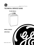
1
Ceiling Sweep Fan
ACES48ALR, ACES48R,SS
Installation Instructions
REGISTERED DESIGN • REGISTERED PATENT
Thank you for purchasing this Airflow Ceiling Sweep Fan. You can be assured of years
of trouble free operation by installing your ceiling fan carefully in accordance to these instructions.
Please read all the instructions before commencing, then complete each step in order.
Included with your Fan
A. Motor Assembly
D. Screw Pack
B. Three Blades
E. Mounting Bracket
C. I.R. Remote Controller
F. Instruction Sheet.
All electrical work must be carried
out by a qualified electrician.
Clearances and Angled Ceilings
18.5o
Blades:
Minimum 2.1m
above floor.
Minimum
300mm from
other obstacles.
Hangsure Mounting
Suitable for pitched ceilings
with a maximum angle of 18.5o.
Controlling a Single Fan
D
This fan has been supplied with a quality remote controller that is
designed to operate a single fan and includes on/off control and
dimming for light fittings.
Hangsure Bracket
IMPORTANT NOTES
1. To ensure proper balance, the blades are a matched set. Do
not mix-up the blades with those from another fan
2. Transport and transit handling may loosen factory fitted
cables. Please check and secure terminal screws before
installation.
1.0 Mounting the Fan Support Bracket
Protecting the Fan
Do not place the motor directly onto a flat surface.
Select a suitable location to mount the fan support bracket.
The mounting bracket must be fixed to a solid structural member
such as a ceiling joist or a securely fixed noggin and be capable
of supporting 15kg.
Additionally it must be located so as to provide the blade with a
minimum clearance from the floor of 2100mm, and from other
obstructions of at least 300mm.
Plastic Nipple
Foam
Packaging
The plastic nipple underneath the motor cannot support the
weight of the motor and may be easily damaged. When working
on the fan, place the motor on the foam packaging with the
nipple located in one of the recesses. This protects the nipple
and the finish.
Hangsure Mounting
Secure fixing to support 15kg
ACES48ALR
Ceiling Sweep Fan Installation Instructions
2.0 Fitting the Blades
4.0 Hanging the Fan
Discard the plastic spacer as illustrated in the diagram below.
Seat the key-slot holes of the blade on the screws of the fan
motor.
Hangsure Bracket
Position the ball-joint in the bracket so that the guide pin on the
bracket engages in the slot in the ball-joint.
Slide the blade to the right as illustrated, until the blade engages
in the locking mechanism and secure the blade with screws.
A
B
Guide Pin
Slot
Foam
Packaging
Support the motor
Remove plastic spacer
Lift the fan up and place the
nylon ball onto the bracket.
D
C
Make sure the guide pin of
bracket is fitted into slot of
ball-joint.
5.0 Installing the Fan
Slide blade over screws
Tighten screws
3.0 Connecting the Light Fitting
If you are attaching a light fitting to the fan, do so prior to hanging
the fan.
NOTE:
Clipper Light (CL) and Oyster Light (OL) may be installed in fans
which are constructed for this purpose.
1. Install the receiver to the
bracket as shown. Connect
the wires according to the
remote control wiring
instructions (page 3)
1. Unscrew the plastic nipple from the bottom of the
motor housing
2. Pull out the light wires from the motor housing for connection
with the lamp holder
3. Insert the light wires through the adaptor, then screw the
adaptor into the motor shaft
4. Connect the light wires to the lamp holder then screw the
lamp holder and the adaptor together firmly.
Light Wires
Plastic Nipple
Light Wires
Adaptor
2. Loosen the screw in the
sensor bracket, insert the
infrared sensor into the hole
on the canopy. Ensure the
infrared sensor is held by
the metal plate as shown
and tighten the screw
3. Manoeuvre the canopy
into place over the mounting
bracket. Ensure that the
infrared sensor is in the
shade and not in direct
sunlight. Slide up top
cowl but allow 5-10mm
clearance. Secure with
locking screws.
Lamp Holder
2 of 4
© Clipsal Australia Pty Ltd
ACES48ALR
Ceiling Sweep Fan Installation Instructions
• The speed can be selected by pressing the ‘SPEED’ button on
the remote control transmitter:
6.0 Connecting the Fan
All Airflow Ceiling Sweep Fans are pre-wired to allow for a light
to be fitted onto the fan.
If you are not fitting a light to the fan, please disregard the light
wires. The wires are connected to the incoming wiring as
illustrated in the below diagram.
BLUE
BROWN
REMOTE CONTROL
RECEIVER
GREEN/YELLOW
RED
BROWN
BLUE
NEUTRAL
ACTIVE
BROWN
SUPPLY
230-240V~ 50Hz
HI - High Speed
MED - Medium Speed
LOW - Low Speed
OFF - Off.
9.0 Operating Instructions
EARTH
BLUE
L
N
RED BROWN BLUE
TO REMOTE
TB1
Light ON/OFF
Fan Speed
Light Dimming
TB2
BROWN BLUE
TO FAN
RED BROWN BLUE
BLUE
BROWN
RED
BROWN
AIRFLOW
REMOTE
CONTROL
BLUE
GREEN/YELLOW
Fan OFF
7.0 Mounting the Remote Control
Mount the cradle in a convenient location. The handset can be
stored in the cradle.
NOTE
Light dimming only works when a light fitting is attached to the
fan and the lamps are compatible with dimmers. Most fluorescent
lamps are not compatible with dimmers.
Summer/Winter Settings
The forward/reversible switch is located on the bottom cowl.
Cradle
SUMMER
Handset
8.0 Operating Your Fan
• Forward/reversible switch on motor housing controls air
movement
Caution: Before changing forward/reversible switch, turn
the fan OFF and ensure that the fan has stopped rotating
to prevent injury to yourself and damage to the motor.
REMOTE CONTROL:
• Use the infrared remote control to change the speed of the fan
as well as to switch both the fan and light on and off. (If a light
fitting is attached to the fan)
• Replace the batteries by sliding the battery compartment
panel on the remote in the direction of the arrow. Fit two
‘AAA’ batteries, ensuring polarity as shown in the battery
compartment. (Note: batteries NOT included). Slide on
the battery compartment cover
• ALWAYS ensure that the battery compartment panel is secure
• NEVER leave the remote control in direct sunlight
• NEVER attempt to recharge primary batteries, either in a
charger or by applying heat to them. There are special
rechargeable batteries which are clearly marked as such
• NEVER dispose of batteries in fire, because this can cause
them to explode
• The light can be controlled on and off by pressing the light
‘ON/OFF’ button on the remote control transmitter
• The level of light brightness can be adjusted by pressing and
holding the ‘DIMMER’ button on the remote control transmitter
© Clipsal Australia Pty Ltd
WINTER
Check switch and make sure it is in correct setting, depending on
cold weather or hot weather.
Cold weather: Push switch down for the blades to circulate the
warm air trapped near the ceiling.
Hot weather: Push switch up for the blades to create a breeze
and circulate the air.
NOTE
The forward/reversible switch must be fully engaged for the fan
to operate.
Cleaning Instructions
To clean the fan, wipe over with a damp, soapy cloth.
Do not use scourers or abrasive cleaners.
ALL ELECTRICAL WORK MUST BE CARRIED
OUT BY A QUALIFIED ELECTRICIAN.
3 of 4
ACES48ALR
Ceiling Sweep Fan Installation Instructions
Troubleshooting Guide
Fan will not switch on:
• Switch off the fan. Then check the following:
• Forward/reversible switch on fan motor not fully engaged in
desired setting
• Connections not as per installation diagram
• Fuse blown, circuit breaker tripped or there is a power failure.
Fan will not operate at varying speed control settings:
• Controller connections not as per page 3.
Ticking, rattling, mechanical noises:
• Ensure all screws and bolts are tight
• Ensure the mounting assembly is secure
• Ensure the lower canopy is clear of the motor
• Ensure the wires are not tapping against the canopy.
WARNING:
• Do not attempt to stop the blades by hand, even at low speed
• This appliance is not intended for use by persons (including
children) with reduced physical, sensory or mental capabilities,
or lack of experience and knowledge, unless they have been given
supervision or instruction concerning use of the appliance by a
person responsible for their safety. Children should be supervised to
ensure that they do not play with the appliance.
For further technical support contact the Clipsal National
Customer Service Centre on 1300 2025 25.
Warranty
The benefits conferred by this warranty are in addition to all implied
warranties, other rights and remedies in respect of the product which
the consumer has under the Trade Practices Act and similar State and
Territory Laws.
The original purchaser of this Airflow Ceiling Sweep Fan, is provided with
the following warranty, subject to the following conditions:
Clipsal Australia Pty Ltd warrant this product for a period of three years
from the date of purchase for all parts defective in workmanship or
materials. All products used in commercial applications are limited to a 90
day warranty.
All defective parts will be replaced free of charge.
The following exclusions do not preclude the purchaser from those
statutory rights consumers have under the Trade Practices Act or similar
State and Territory Laws.
WARRANTY CONDITIONS:
1. This warranty, is only valid for appliances installed according to the
manufacturers instructions
2. This appliance must not be modified or changed in any way
and all electrical connections must be carried out by a
qualified electrician only
3. Connection must be to the voltage requirements as specified in the
ratings label located on the product
4. The manufacturer does not accept liability for any direct or
consequential damage, loss or other expense arising from misuse
or incorrect installation and operation of the appliance
5. Warranty will only be given where proof of purchase is provided,
eg. original invoice
6. For warranty to be valid only Airflow accessories, such as down rods
and light kits, shall be installed with the Airflow Ceiling Sweep Fan.
ALSO AVAILABLE FROM
C-ThruTM Electronic Fan Controllers
IMPORTANT
Record this warranty information at the time of purchase but do not send
this information unless you are making a claim or are asked to
do so.
To obtain service under warranty you must retain your original purchase
receipt, service will otherwise be charged at current rates.
Model No.:
Purchase from:
• Rapid Fan Start Feature
• Variable Speed Adjustment
Name:
Address:
• Control up to Eight Airflow Fans
Postcode:
• Multiple Plate Styles Available.
Date of purchase:
Product of Clipsal Australia Pty Ltd
A member of Schneider Electric
Contact us clipsal.com/feedback
National Customer Service Enquiries:
Tel 1300 2025 25
Fax
1300 2025 56
4 of 4
F2130
clipsal.com
Clipsal Australia Pty Ltd reserves the right to change specifications, modify designs and
discontinue items without incurring obligation and whilst every effort is made to ensure that
descriptions, specifications and other information in this catalogue are correct, no warranty is
given in respect thereof and the company shall not be liable for any error therein.
© Clipsal Australia Pty Ltd.
The identified trademarks and copyrights are the property of Clipsal Australia Pty Ltd unless
otherwise noted.
© Clipsal Australia Pty Ltd
CLIPCOM 16952 July 2008