1
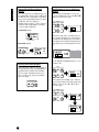
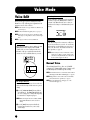
OWNER’S MANUAL
SPECIAL MESSAGE SECTION
This product utilizes batteries or an external power supply (adapter). DO NOT
connect this product to any power supply or adapter other than one
described in the manual, on the name plate, or specifically recommended by
Yamaha.
WARNING:
Do not place this product in a position where anyone could walk on, trip over,
or roll anything over power or connecting cords of any kind. The use of an
extension cord is not recommended! IF you must use an extension cord, the
minimum wire size for a 25' cord (or less ) is 18 AWG. NOTE: The smaller the
AWG number ,the larger the current handling capacity. For longer extension
cords, consult a local electrician.
This product should be used only with the components supplied or; a cart,
rack, or stand that is recommended by Yamaha. If a cart, etc., is used, please
observe all safety markings and instructions that accompany the accessory
product.
SPECIFICATIONS SUBJECT TO CHANGE:
The information contained in this manual is believed to be correct at the time
of printing. However, Yamaha reserves the right to change or modify any of
the specifications without notice or obligation to update existing units.
This product, either alone or in combination with an amplifier and headphones
or speaker/s, may be capable of producing sound levels that could cause
permanent hearing loss. DO NOT operate for long periods of time at a high
volume level or at a level that is uncomfortable. If you experience any hearing
loss or ringing in the ears, you should consult an audiologist.
IMPORTANT: The louder the sound, the shorter the time period before
damage occurs.
Some Yamaha products may have benches and / or accessory mounting
fixtures that are either supplied with the product or as optional accessories.
Some of these items are designed to be dealer assembled or installed. Please
make sure that benches are stable and any optional fixtures (where
applicable) are well secured BEFORE using.
Benches supplied by Yamaha are designed for seating only. No other uses
are recommended.
Battery Notice:
This product MAY contain a small non-rechargeable battery which (if
applicable) is soldered in place. The average life span of this type of battery
is approximately five years. When replacement becomes necessary, contact a
qualified service representative to perform the replacement.
This product may also use “household” type batteries. Some of these may be
rechargeable. Make sure that the battery being charged is a rechargeable
type and that the charger is intended for the battery being charged.
When installing batteries, do not mix batteries with new, or with batteries of a
different type. Batteries MUST be installed correctly. Mismatches or incorrect
installation may result in overheating and battery case rupture.
Warning:
Do not attempt to disassemble, or incinerate any battery. Keep all batteries
away from children. Dispose of used batteries promptly and as regulated by
the laws in your area. Note: Check with any retailer of household type
batteries in your area for battery disposal information.
Disposal Notice:
Should this product become damaged beyond repair, or for some reason its
useful life is considered to be at an end, please observe all local, state, and
federal regulations that relate to the disposal of products that contain lead,
batteries, plastics, etc. If your dealer is unable to assist you, please contact
Yamaha directly.
NAME PLATE LOCATION:
The name plate is located on the bottom of the product. The model number,
serial number, power requirements, etc., are located on this plate. You should
record the model number, serial number, and the date of purchase in the
spaces provided below and retain this manual as a permanent record of your
purchase.
Model
NOTICE:
Service charges incurred due to a lack of knowledge relating to how a
function or effect works (when the unit is operating as designed) are not
covered by the manufacturer’s warranty, and are therefore the owners
responsibility. Please study this manual carefully and consult your dealer
before requesting service.
Serial No.
Purchase Date
ENVIRONMENTAL ISSUES:
Yamaha strives to produce products that are both user safe and
environmentally friendly. We sincerely believe that our products and the
production methods used to produce them, meet these goals. In keeping with
both the letter and the spirit of the law, we want you to be aware of the
following:
PLEASE KEEP THIS MANUAL
92-BP (bottom)
PRECAUTIONS
PLEASE READ CAREFULLY BEFORE PROCEEDING
* Please keep these precautions in a safe place for future reference.
WARNING
Always follow the basic precautions listed below to avoid the possibility of serious injury or even death from electrical shock,
short-circuiting, damages, fire or other hazards. These precautions include, but are not limited to, the following:
• Do not open the instrument or attempt to disassemble the internal parts or
modify them in any way. The instrument contains no user-serviceable parts. If it
should appear to be malfunctioning, discontinue use immediately and have it
inspected by qualified Yamaha service personnel.
• Do not expose the instrument to rain, use it near water or in damp or wet
conditions, or place containers on it containing liquids which might spill into
any openings.
• If the AC adaptor cord or plug becomes frayed or damaged, or if there is a
sudden loss of sound during use of the instrument, or if any unusual smells or
smoke should appear to be caused by it, immediately turn off the power switch,
disconnect the adaptor plug from the outlet, and have the instrument inspected
by qualified Yamaha service personnel.
• Use the specified adaptor (PA-3C or an equivalent recommended by Yamaha)
only. Using the wrong adaptor can result in damage to the instrument or
overheating.
• Before cleaning the instrument, always remove the electric plug from the outlet.
Never insert or remove an electric plug with wet hands.
• Check the electric plug periodically and remove any dirt or dust which may
have accumulated on it.
CAUTION
Always follow the basic precautions listed below to avoid the possibility of physical injury to you or others, or damage to the
instrument or other property. These precautions include, but are not limited to, the following:
• Do not place the AC adaptor cord near heat sources such as heaters or
radiators, and do not excessively bend or otherwise damage the cord, place
heavy objects on it, or place it in a position where anyone could walk on, trip
over, or roll anything over it.
• When removing the electric plug from the instrument or an outlet, always hold
the plug itself and not the cord.
• Do not connect the instrument to an electrical outlet using a multipleconnector. Doing so can result in lower sound quality, or possibly cause
overheating in the outlet.
• Unplug the AC power adaptor when not using the instrument, or during
electrical storms.
• Before connecting the instrument to other electronic components, turn off the
power for all components. Before turning the power on or off for all
components, set all volume levels to minimum. Also, be sure to set the
volumes of all components at their minimum levels and gradually raise the
volume controls while playing the instrument to set the desired listening level.
• Do not expose the instrument to excessive dust or vibrations, or extreme cold
or heat (such as in direct sunlight, near a heater, or in a car during the day) to
prevent the possibility of panel disfiguration or damage to the internal
components.
• Do not use the instrument near other electrical products such as televisions,
radios, or speakers, since this might cause interference which can affect proper
operation of the other products.
• Do not place the instrument in an unstable position where it might accidentally
fall over.
• Before moving the instrument, remove all connected adaptor and other cables.
• When cleaning the instrument, use a soft, dry cloth. Do not use paint thinners,
solvents, cleaning fluids, or chemical-impregnated wiping cloths. Also, do not
place vinyl, plastic or rubber objects on the instrument, since this might
discolor the panel or keyboard.
• Use only the stand specified for the instrument. When attaching the stand or
rack, use the provided screws only. Failure to do so could cause damage to the
internal components or result in the instrument falling over.
• Do not operate the instrument for a long period of time at a high or
uncomfortable volume level, since this can cause permanent hearing loss. If
you experience any hearing loss or ringing in the ears, consult a physician.
■ REPLACING THE BACKUP BATTERY
• This instrument contains a non rechargeable internal backup battery which
permits internal data to remain stored even when the power is off. When the
backup battery needs replacing, the message “!BatteryLo” will display in the
LCD. When this happens, immediately back up your data (using an external
device such as the floppy disk-based Yamaha MIDI Data Filer MDF3), then
have qualified Yamaha service personnel replace the backup battery.
• Do not attempt to replace the backup battery yourself, in order to prevent the
possible serious hazards. Always have qualified Yamaha service personnel
replace the backup battery.
• Never place the backup battery in a location that a child can reach, since a child
might accidentally swallow the battery. If this should happen, consult a
physician immediately.
■ SAVING USER DATA
• Save all data to an external device such as the Yamaha MIDI Data Filer MDF3,
in order to help prevent the loss of important data due to a malfunction or user
operating error.
Yamaha cannot be held responsible for damage caused by improper use or
modifications to the instrument, or data that is lost or destroyed.
Always turn the power off when the instrument is not in use.
• Do not rest your weight on, or place heavy objects on the instrument, and do
not use excessive force on the buttons, switches or connectors.
(3)-6
Introduction
Thank you for purchasing the Yamaha S03 Music Synthesizer. In order to get the most out of your new S03 and its
sophisticated functions, we suggest you read through this manual thoroughly. Also keep it in a safe, convenient place
so that you can regularly refer to it when necessary.
Package Contents
• PA-3C AC Adaptor *
n Since the PA-3C has the same specifications as the PA-3B, the PA-3C can be used as the AC adapter for any product
requiring the PA-3B.
• Owner’s Manual
• Data List
* May not be included in your area. Please check with your Yamaha dealer.
Main Features
• Exceptionally high-quality dynamic Voices — including many sounds from Yamaha’s top-of-the-line S80 Music
Synthesizer (page 18).
• Wide variety of pro-quality digital effects (page 53).
• Category Search function for quickly calling up Voices in a desired instrument group (page 35).
• A total of 480 Normal Voices and 20 Drum Voices, all XG-compatible — in addition to Preset Voices and User
Voices (page 25).
• Comprehensive, detailed editing features for customizing your Voices (page 70).
• Convenient TO HOST terminal for direct, easy connection to computer — with just one cable (page 13).
GM System Level 1
“GM System Level 1” is a standard specification that defines the arrangement of voices in a tone generator and its MIDI
functionality, ensuring that data can be played back with substantially the same sounds on any GM-compatible tone
generator, regardless of its manufacturer or model. Tone generators and song data that meet the “GM System Level 1” bear
this GM logo.
XG
“XG” is a tone generator format that expands the voice arrangement of the “GM System Level 1” specification to meet the
ever-increasing demands of today’s computer peripheral environment, providing richer expressive power while maintaining
upward compatibility of data. “XG” greatly expands “GM System Level 1” by defining the ways in which voices are expanded
or edited and the structure and type of effects.
When commercially available song data bearing the XG logo is played back on a tone generator which bears the XG logo, you
will enjoy a full musical experience that includes unlimited expansion voices and effect functions.
4
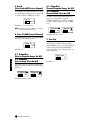
About This Manual
This manual is basically divided into two sections:
■ Basics Section (Page 8)
Explains how to get started with the S03, it’s overall structure, and how to use its main features and functions.
■ Reference Section (Page 55)
Explains the parameters of the S03’s various modes.
About the “Page” References in this Manual
PAGE xx ..... Refers to a display “page” in the LCD
page xx ........ Refers to an actual page in this manual.
Many of the functions and parameters of the S03 are shown on various display “pages,” each of which is numbered
within each mode and indicated in the display. Searching for a function or parameter is made more convenient and
fast by the use of these page numbers.
To distinguish these display page references from actual pages in the manual, we’ve applied the following convention:
“PAGE” (all capital letters) refers to the display page. Unless indicated otherwise, the PAGE reference is for display
pages within the same mode (as described for other parameters in the same section).
Throughout the manual, parameter names are prefaced by numbers, such as “13-2 Resonance.” This, for example,
indicates that the Resonance parameter is on display PAGE 13 in the selected mode.
When one display page contains two or more related parameters, use the [E]/[F] buttons (page 30) to scroll
through the available parameters. These related parameters selected by the [E]/[F] buttons are indicated by
hyphenated numbers (e.g., 13-1, 13-2, etc.). In the example above, you can select the Resonance parameter by using
the [E]/[F] buttons to move to the second page.
n For a full listing of the parameters and their corresponding display pages, refer to the Function Tree chart (page 20) or the
Parameter Table (page 22).
● Copying of the commercially available music sequence data and/or digital audio files is strictry prohibited except
for your personal use.
● The illustrations and LCD screens as shown in this owner’s manual are for instructional purposes only, and may
appear somewhat different from those on your instrument.
● The company names and product names in this Owner’s Manual are the trademarks or registered trademarks of
their respective companies.
5
Table of Contents
Basics Section............................8
Reference Section ....................55
The Controls & Connectors ................................................ 8
Multi Mode ......................................................................... 55
Front Panel ................................................................................... 8
Rear Panel .................................................................................. 10
Multi Edit................................................................................... 55
Common (Settings for all Parts) ........................................... 56
Part (Settings for each Part).................................................. 59
Multi Job.................................................................................... 67
Performing a Job................................................................... 67
Multi Store................................................................................. 69
Before Use ........................................................................... 11
Power Supply ............................................................................. 11
Connections................................................................................ 11
Powering Up .............................................................................. 15
Demo Playback................................................................... 16
Voice Mode ......................................................................... 70
About the Modes ................................................................ 19
Voice Edit .................................................................................. 70
Normal Voice ....................................................................... 70
Drum Voices......................................................................... 84
Voice Job ................................................................................... 87
Performing a Job................................................................... 87
Voice Store ................................................................................ 89
Function Tree chart ........................................................... 20
Utility Mode........................................................................ 90
Overview of the S03 ........................................................... 17
Controller ................................................................................... 17
Tone Generator .......................................................................... 17
Effects ........................................................................................ 18
Parameter Table................................................................. 22
Utility Job .................................................................................. 92
Factory Set (Restore Factory Defaults) ................................ 92
Multis .................................................................................. 24
MIDI Mode......................................................................... 93
Voices .................................................................................. 25
Overview of Voices/Waves ....................................................... 26
Waves......................................................................................... 27
Appendix ................................95
Basic Operations ................................................................ 28
About MIDI ........................................................................ 95
Selecting a Mode........................................................................ 28
Selecting a Screen ...................................................................... 30
Entering Data ............................................................................. 31
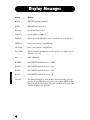
Display Messages.............................................................. 100
Playing the S03 ................................................................... 33
Playing the Voices ..................................................................... 33
Using Multi Mode .............................................................. 37
Playing in Multi Mode ............................................................... 37
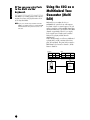
Using the S03 as a Multitimbral Tone Generator (Multi Edit) .. 38
Performing Live While Playing Back a Song File..................... 40
Splitting the Keyboard — Setting Upper and Lower Ranges for the Voices .... 41
Layering Two Voices (Parts) Together...................................... 42
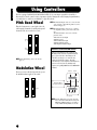
Using Controllers ............................................................... 44
Pitch Bend Wheel ...................................................................... 44
Modulation Wheel ..................................................................... 44
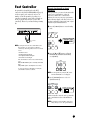
Foot Controller........................................................................... 45
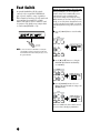
Foot Switch ................................................................................ 46
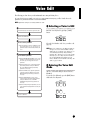
Voice Edit............................................................................ 47
Effects.................................................................................. 53
Effects in Voice Mode ............................................................... 53
Effects in Multi Mode ................................................................ 53
6
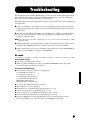
Troubleshooting ............................................................... 101
Specifications.................................................................... 105
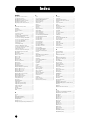
Index.................................................................................. 106
This convenient, easy-to-use index is divided to general categories to help you when you want to find information on a specific topic or
function.
Multi Mode
Listening/Playing
• Listening to Demo songs ........................................................................................................................................ Demo Playback (Page 16)
• Playing the voices............................................................................................................................................................................... (Page 33)
• Calling up Voices in a desired instrument group .............................................................................Using Voice Category Search (Page 35)
• Performing live while playing back a Song file ................................................................................................................................ (Page 40)
• Splitting the keyboard — Setting upper and lower ranges for the Voices
In Multi mode .................................................................................................................................................................................... (Page 41)
In Voice mode.................................................................................................................................................................. Note Limit (Page 73)
• Layering two voices (Parts together) ................................................................................................................................................ (Page 42)
Basics Section
Application Index
Using controllers
• Connecting controllers ...................................................................................................................................................................... (Page 14)
• Using a Foot Controller to control parameters................................................................................................................................. (Page 45)
• Using a Footswitch to advance through Voice or Multi programs .................................................................................................. (Page 46)
• Maintaining the controller state/position when you switch between voices..................................................... Controller Reset (Page 91)
• Setting the AC1 (Assignable Controller 1) Controller ..........................................................................................Foot Controller (Page 45)
AC1 (Assignable Controller 1) (Page 66)
Voice Mode
Copying
• Copying the Voice Variation Effect settings to the Multi mode ..................................................................Copy Variation Effect (Page 68)
• Copying the Controller settings of the Voice mode to the Multi mode ...............................................................Copy Controller (Page 68)
• Copying Part parameter settings of the Multi being edited to another Part in the same Multi..................................................... (Page 68)
• Copying Element parameter settings of the Voice being edited to another Element in the same Voice ....................................... (Page 88)
• Backing up your S03 data............................................................................................Saving S03 Settings to an External Device (Page 42)
Utility Mode
MIDI Mode
Changing the sound
• Editing a Voice ................................................................................................................................................................. Voice Edit (Page 47)
• Effect structure and signal flow ............................................................................................................................................ Effects (Page 53)
• Details on the parameters of the modes .............................................................................................................Reference Section (Page 55)
Saving data
• Storing the edited Voice to the S03 internal (USER) memory.....................................................................................Voice Store (Page 89)
• Storing the edited Multi to the S03 internal (USER) memory ................................................................................... Multi Store (Page 69)
• Saving S03 settings (Voice/Multi/MIDI/Utility) to an external device such as a computer .......... Saving S03 Settings to an External Device (Page 42)
Resetting parameters (Initializing)
• Initializing Multi parameters ............................................................................................................................................ Initialize (Page 68)
• Initializing Voice parameters............................................................................................................................................. Initialize (Page 88)
• Resetting the S03 to its default settings............................................................................Factory Set (Restore Factory Defaults) (Page 92)
Quick solutions
• Global functions of the S03.............................................................................................................................Function Tree chart (Page 20)
• S03 parameter structure and the LCD PAGES..................................................................................................... Parameter Table (Page 22)
• General information on MIDI......................................................................................................................................About MIDI (Page 95)
• Meaning of the display messages ...................................................................................................................... Display Messages (Page 100)
• Troubleshooting................................................................................................................................................................................(Page 101)
7
Appendix
Connecting the S03 to other devices
• Connecting a computer............................................................................................................... Connecting a Personal computer (Page 13)
• Setting Local On/Off .................................................................................................................................................. Local On/Off (Page 93)
• Using the S03 as a multitimbral tone generator............................................................................................................................... (Page 38)
• Sending the S03 data using the Bulk Dump function ...............................................Saving S03 Settings to an External Device (Page 42)
Basics Section
Basics Section
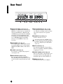
The Controls & Connectors
Font Panel
1
PHONES
OUTPUT
L MONO
R
DC IN
STANDBY
ON
FOOT
CONTROLLER
FOOT
SWITCH
2
TO HOST
HOST SELECT
5
IN
MIDI
OUT
6
7
8
9)! $
THRU
EDIT
VOLUME
UTILITY MIDI
MULTI PART
VOICE COMMON
MODE
MULTI
VOICE
PART ELEMENT KEY
DEMO
CATEGORY
SEARCH
DRUM
PAGE
MUSIC SYNTHESIZER
ELEM KEY
KEY
PART ELEM
MIDI
OCTAVE
VOICE
OSC MIX
TG
MIX
PITCH
KEYBOARD
GENERAL
FILTER
MIDI CHANNEL
TONE
AMP
MIDI FILTER
CONTROLLER
LFO
CONTROLLER
EFFECT
EFFECT
EFFECT
UP
DATA
UTILITY
MIDI
EDIT
JOB
COMPARE
3 4
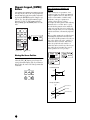
1 OCTAVE [UP] and [DOWN] buttons (Page 36)
Press either of these buttons to shift the note range
of the keyboard up or down in octaves. Press them
together to restore the normal range (0).
2 [VOLUME] slider (Page 15)
Adjusts the master volume output from the
OUTPUT L/R jacks and the PHONES jack. Move
the slider upwards to raise the level.
3 PITCH bend wheel (Page 44)
Controls the pitch bend effect.
4 MODULATION wheel (Page 44)
Controls the modulation effect. You can also assign
other parameters and functions to this controller.
5 LCD (Liquid Crystal Display)
This backlit LCD displays various operation
messages and information.
6 Parameter Type List (Page 30)
Follow the arrow in the LCD across to the
appropriate column in the list; the arrow indicates
the type of the currently selected parameter.
8
8
9
ORGAN
5
GUITAR
6
COMMON
DEC NO
OCTAVE
DOWN
7
PIANO
4
MUTE
ELEMENT
PRESET
UTILITY
STORE
INC YES
DRUM/PERC
USER
SE
GM XG
OTHER
@#
BASS
1
STRINGS
2
BRASS
3
REED/PIPE
0
SYN LEAD
SYN PAD
ENTER
SYN COMP
CHROMATIC KEYBOARD
PERCUSSION
EXIT
%^
7 MODE buttons (Page 19)
Press these to buttons to select one of the modes:
Multi, Voice, Utility, or another mode.
8 [PART/ELEMENT/KEY] buttons
These buttons are used to select Parts/Elements/
Drum keys in the Multi Edit or Voice Edit Mode.
8-1 [+]/[–] buttons (Page 30)
In the Multi Mode, these buttons select Parts 1 to
16. In the Multi Part Edit mode, press both of these
buttons simultaneously to call up the Common Edit
screens. To return to the Part Edit screens, press
only one of these buttons, [–] or [+].
In the Voice Edit Mode, these buttons select
Elements 1 to 4 or the Drum keys. In the Voice
Element Edit mode, press both of these buttons
simultaneously to call up the Common Edit screens.
To return to the Element Edit screens, press only
one of these buttons, [–] or [+].
8-2 [MUTE] button (Page 48, 55)
In the Multi Mode, this button mutes the selected
Parts. In the Voice Edit Mode, this button mutes the
selected Elements or Drum keys.
9-1 [DEC/NO] button (Page 31)
Use this to decrease the value of the selected
parameter. To decrease the value by 10,
simultaneously hold down this button and press the
[INC/YES] button. The button can also be used to
cancel a Job or Store operation.
9-2 [INC/YES] button (Page 31)
Use this to increase the value of the selected
parameter. To increase the value by 10,
simultaneously hold down this button and press the
[DEC/NO] button. The button can also be used to
execute a Job or Store operation.
9-3 [ ▲ ]/[ ▼ ] buttons (Page 30)
Use these to select the screen “pages” in each Mode.
9-4 [E]/[F] buttons (Page 30)
Use these to select the value to be set in the LCD, or
to display continuous parts of the page (on the left
and right), for pages that consist of several parts.
) [CATEGORY SEARCH/DRUM] button
(Pages 34, 35)
Turns on the Category Search function (page 35).
This function allows you to instantly select a
desired Voice category from the numeric keypad or
the Memory buttons. You can also assign the drum
bank of each memory by simultaneously pressing
this button and the [USER/(SE)] button or the
[GM/XG /(OTHER)] button.
! [PRESET/(DRUM/PERC)] button (Page 33)
In the Multi and Voice modes, this lets you select
the Preset Memory programs. When the Category
Search function (page 35) is active, this is used to
specify the DRUM/PERC Voice category.
@ [USER/(SE)] button (Page 33)
In the Multi and Voice modes, this lets you select
the User Memory programs. You can also specify a
User Memory Drum bank by simultaneously
pressing both this button and the [CATEGORY
SEARCH/DRUM] button. When the Category
Search function (page 35) is active, this is used to
specify the SE Voice category.
# [GM/XG/(OTHER)] button (Page 33)
In the Multi and Voice modes, this lets you select
the GM/XG Memory programs. You can also
specify a GM/XG Memory Drum bank by
simultaneously pressing both this button and the
[CATEGORY SEARCH/DRUM] button. When the
Category Search function (page 35) is active, this is
used to specify the OTHER: CO, ME Voice
categories.
$ Numeric keypad (Pages 32, 35)
This is used to select specific Multi or Program
numbers. In the Edit mode, it is used to input
parameter data values. The selected value is actually
entered or executed only after pressing the
[ENTER] button. This is also used to select the
various Voice categories (page 70) when the
Category Search function (page 35) is set to ON.
% [ENTER/KEYBOARD] button
This is used to enter or execute the value typed in
from the numeric keypad. This can also be used to
set parameters whose values are expressed as a note
(from C-2 - G8); simultaneously hold this button
and press the desired key on the keyboard. It is also
used for executing various jobs and store
operations.
& [EXIT] button (Page 31)
During editing or when in a mode other than Multi/
Voice Play, pressing this button exits from the mode
and returns to the Multi/Voice Play mode.
9
Basics Section
9 DATA buttons (Page 30)
These are used during editing for selecting various
pages and for setting parameter values.
Basics Section
Rear Panel
THRU
MIDI
OUT
1
IN
HOST SELECT
PC-2 Mac
MIDI
OFF
TO HOST
2 3
FOOT
SWITCH
4 5
1 MIDI IN/OUT/THRU terminals (Page 12)
MIDI IN receives MIDI messages from an external
MIDI device. Use this connector to control the S03
from an external MIDI device. MIDI OUT sends
out MIDI messages generated by the S03 (including
notes played on the keyboard and panel control
movements) to an external MIDI sound module or
device. MIDI THRU simply relays the MIDI
messages received at MIDI IN. Connect other
devices here.
2 HOST SELECT switch (Page 12)
For selecting the type of computer connected to the
S03 via the TO HOST connector. When using the
MIDI IN/OUT/THRU terminals, set this switch to
MIDI.
3 TO HOST terminal (Page 13)
For connection to a computer, using an optional
serial computer cable.
4 FOOT SWITCH jack (Pages 14, 46)
For connecting an optional footswitch (FC4 or
FC5). Depending on the assigned function, you can
use the footswitch to turn specific functions on and
off.
10
FOOT
CONTROLLER
STANDBY
ON
DC IN
6 7
R
OUTPUT
L MONO
PHONES
8
9
5 FOOT CONTROLLER jack (Pages 14, 45)
For connecting an optional foot controller (FC7,
etc.). This gives you real-time control over various
aspects of the sound, such as tone, pitch, and
volume.
6 STANDBY/ON switch (Page 15)
Use this to turn the S03 on or off.
Even when the switch is in the “STANDBY” position,
electricity is still flowing to the instrument at a minimum
level. When not using the S03 for an extended period of
time, be sure to unplug the AC power adaptor from the
wall AC outlet.
7 DC IN terminal (Page 11)
For connecting an appropriate AC power adaptor
(PA-3C or an equivalent recommended by Yamaha)
to supply power to the S03.
8 OUTPUT L/MONO and R jack (Page 11)
Line level audio signals are output from the S03 via
these phone jacks (1/4" mono phone plug). For
monophonic output, use just the L/MONO jack.
9 PHONES jack (Page 11)
For connection to a pair of stereo headphones.
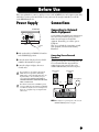
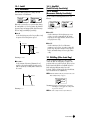
This section explains how to connect to an AC power source, audio and MIDI devices, and a computer system. Only
switch the S03 on after you have made all the necessary connections. We strongly recommended you read this
section BEFORE using the S03.
Power Supply
Connections
S03 Rear Panel
STANDBY
ON
DC IN
R
OUTPUT
L MONO
PHONES
DC IN
To electrical
outlet
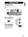
1 Make sure that the S03’s STANDBY/ON switch is
at the STANDBY (off) position.
2 Connect the PA-3C’s DC plug to the S03’s DC IN
terminal on the instrument’s rear panel.
3 Connect the adaptor’s AC plug to the nearest
electrical outlet.
Do not attempt to use an AC adaptor other than the
Yamaha PA-3C or an equivalent recommended by
Yamaha. The use of an incompatible adaptor may cause
irreparable damage to the S03, and may even pose a
serious shock hazard! ALWAYS UNPLUG THE AC
ADAPTOR FROM THE AC POWER OUTLET WHEN
THE S03 IS NOT IN USE.
Even when the switch is in the “STANDBY” position,
electricity is still flowing to the instrument at a minimum
level. When not using the S03 for an extended period of
time, be sure to unplug the AC power adaptor from the
wall AC outlet.
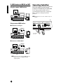
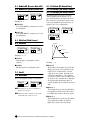
Connecting to External
Audio Equipment
Since the S03 has no built-in speakers, you need to
monitor its sound output via external audio
equipment. Alternatively, you could use a pair of
headphones.
There are several methods of connecting to external
audio equipment, as described in the following
illustrations.
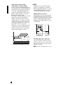
Connecting Stereo Powered
Speakers
A pair of powered speakers can accurately produce the
S03’s rich sounds with their own pan and effect
settings. Connect your powered speakers to the
OUTPUT L/MONO and R jacks on the rear panel.
Powered speaker
(Left)
Powered speaker
(Right)
Stereo headphones
INPUT
OUTPUT L /
MONO
INPUT
OUTPUT R
PHONES
S03
n When using just one powered speaker, connect it to the
OUTPUT L/MONO jack on the rear panel.
11
Basics Section
Before Use
Basics Section
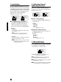
Connecting to a Mixer
If you want to integrate the S03 into a larger system
with other instruments and additional audio
processing capabilities, connect it to a mixer, amplifier
and stereo monitor system as shown below.
Speaker
Connecting External MIDI
Equipment
You can connect an external MIDI device using a MIDI
cable (available separately) and control it from the S03.
You can also use an external MIDI keyboard or
sequencer to control the S03’s internal sounds. This
section introduces several different MIDI applications.
Amplifier
L
R
Mixer
OUTPUT L
R
Stereo headphones
1
2
3
4
5
6
7
8
9
10
11
12
13
14
15
16
OUTPUT
L / MONO
L
n The HOST SELECT switch on the rear panel should be
set to “MIDI” Otherwise, MIDI data will not be
transmitted from the S03’s MIDI OUT connector.
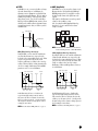
Controlling the S03 from an
External MIDI Keyboard
R
OUTPUT
R
HOST SELECT
PC-2 Mac
PHONES
MIDI
OFF
MIDI IN
S03
n Connecting a pair of headphones does not affect audio
output from the OUTPUT (L/MONO and R) jacks.
The audio output at the PHONES jack and the OUTPUT
jacks is exactly the same.
S03
MIDI OUT
External MIDI keyboard
or synthesizer
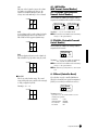
Controlling an External MIDI
Keyboard with the S03
HOST SELECT
PC-2 Mac
MIDI
OFF
MIDI IN
S03
MIDI OUT
External MIDI keyboard
or synthesizer
12
MIDI IN
HOST SELECT
MIDI OUT
PC-2 Mac
MIDI
OFF
External
MIDI sequencer
MIDI OUT
S03
Controlling Another MIDI Device via
MIDI THRU
HOST SELECT
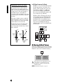
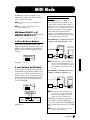
1: Serial connection (the computer’s serial port to
the S03’s TO HOST terminal)
2: MIDI connection (the computer’s MIDI
interface or external MIDI interface to the
S03’s MIDI IN and OUT)
Depending on your particular computer, the
connections may differ. (See below.)
n You may also want to change the Local On/Off setting
(page 93), depending on how you are using the S03 in
your MIDI system.
External MIDI
synthesizer
MIDI OUT
PC-2 Mac
MIDI
You can use a connected computer to control the S03
and to transfer S03 data to/from computer via MIDI.
There are two ways to connect your S03 to a computer:
MIDI IN
External
MIDI sequencer
Connecting to a Personal
Computer
MIDI IN
1: Serial Port to TO HOST
OFF
MIDI IN
MIDI THRU
IBM-PC/AT
MIDI OUT
HOST SELECT
8-pin MINI DIN to
D-SUB 9-pin Cable
PC-2 Mac
MIDI
OFF
TO
HOST
S03
PS/V
Personal System/V
Personal System/V
IBM
MIDI IN
RS-232C
(DB9)
External MIDI synthesizer
With the above MIDI connections, you can send MIDI
data from the S03’s MIDI OUT terminal, while
sending MIDI data from the external sequencer to an
external MIDI synthesizer via the S03’s MIDI THRU
terminal.
n The MIDI cable should be no greater than 15 meters in
length, and there should be no more than three devices in
a MIDI chain (chained in series via each unit’s MIDI
THRU). To connect more units, use a MIDI Thru Box
for parallel connections. You may encounter errors if the
MIDI cables are too long or if too many devices are
chained together via their MIDI THRU connectors.
S03
IBM-PC/AT
and compatibles
mini DIN 8-pin
D-SUB 9-pin
Macintosh
HOST SELECT
PC-2 Mac
MIDI
OFF
Macintosh Peripheral
Cable (M0197)
TO
HOST
S03
mini DIN 8-pin
Macintosh
mini DIN 8-pin
13
Basics Section
Recording and Playback using an
External MIDI Sequencer
Basics Section
2: MIDI Interface to MIDI IN and OUT
Connecting Controllers
Using the computer’s MIDI interface
The S03 has controller jacks on the rear panel,
including FOOT SWITCH and FOOT CONTROLLER.
You can connect optional controllers such as a
footswitch (the FC4 or FC5) and foot controller (the
FC7) to control tone, volume, pitch and other
parameters.
HOST SELECT
PC-2 PC-1
MIDI
Mac
MIDI IN
MIDI OUT
n Details about how to use these controllers are given on
page 45.
NEC MultiSync
MIDI
OUT
MIDI
IN
S03
PC-9821 AS
NEC
Computer with
MIDI interface
S03
HOST SELECT
PC-2 Mac
DI
Using an external MIDI interface
OFF
TO HOST
FOOT
SWITCH
FOOT
CONTROLLER
STANDBY
ON
DC IN
R
OUTPUT
L MONO
PHONES
■ Connection to serial port
MIDI Interface
HOST SELECT
MIDI OUT
PC-2 Mac
MIDI
OFF
FOOT CONTROLLER
FC7
MIDI IN
MIDI IN
MIDI OUT
FOOT SWITCH
FC4 or FC5
Computer
S03
■ Connection to USB terminal
USB-MIDI interface
(UX256, etc.)
MIDI OUT
HOST SELECT
PC-2 Mac
MIDI
OFF
MIDI IN
MIDI IN
S03
MIDI OUT
Computer
n You will also need the appropriate MIDI application
(sequencer, editor, etc.), compatible with your
computer platform.
14
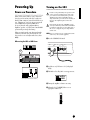
Turning on the S03
Power-on Procedure
In order to avoid possible damage to the speakers or other
connected electronic equipment, always switch on the
power of the S03 before switching on the power of the
amplified speakers or mixer and amplifier. Likewise,
always switch off the power of the S03 after switching off
the power of the amplified speakers or mixer and
amplifier.
When you have made all the necessary connections
between your S03 and any other devices, make sure
that all volume settings are turned down all the way to
zero. Then turn on every device in your setup in the
order of MIDI masters (senders), MIDI slaves
(receivers), then the audio equipment (mixers,
amplifiers, speakers, etc.). This ensures smooth MIDI
operation and prevents speaker damage.
When powering down the setup, first turn down the
volume for each audio device, then switch off each
device in the reverse order (first audio devices, then
MIDI).
Even when the switch is in the “STANDBY” position,
electricity is still flowing to the instrument at a minimum
level. When not using the S03 for an extended period of
time, be sure to unplug the AC power adaptor from the
wall AC outlet.
n Before you switch your S03 on or off, first turn down the
volume of any connected audio equipment.
1 Press the STANDBY/ON switch
When using the S03 as MIDI slave:
H
FOOT
CONTROLLER
STANDBY
ON
DC IN
R
OUTPUT
L MONO
PHONES
MIDI master (transmitting device)
POWER
ON!!
S03 as MIDI slave (MIDI receiving device)
2 A splash screen (“Welcome to S03”) is displayed
briefly.
3 The Multi or Voice Play Mode screen appears next.
1
2
3
4
5
6
7
8
9
10
11
12
13
14
15
16
L
R
PAGE
Audio equipment (first mixer, then amplifier)
GrandPno
XG001
PART ELEM KEY
OCTAVE
4 Turn up the amplifier’s volume as necessary.
5 Adjust the S03’s [VOLUME] slider to set an
appropriate volume level.
VOLUME
15
Basics Section
Powering Up
Basics Section
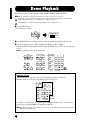
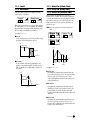
Demo Playback
The S03 features a variety of demo songs, showcasing its dynamic sound and sophisticated functions.
n Make sure synthesizer is ready for playback. Details are given in the section “Before Use” on page 11.
At the “Demo” screen, any data in the instrument’s User Voice memory will be overwritten by the data for the demo song.
Important data should be saved to the external MIDI device or computer beforehand.
At the “DEMO” screen, the Master Tune parameter (in Utility) will be overwritten and set to “0.”
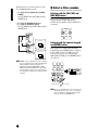
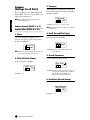
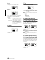
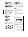
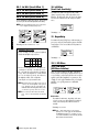
1 Press the [DEMO] button.
The following screen appears.
MODE
MULTI
VOICE
EraseUserV
OK?
DEMO
PART ELEM KEY
PAGE
OCTAVE
2 Press the [INC/YES] button to call up the Demo screen and automatically start playback of the Demo song.
3 To stop Demo playback, press one of the following buttons: [MULTI], [VOICE], or [EXIT].
This exits from the Demo mode and automatically returns to the Multi mode, Voice mode, or the mode previously
selected.
n Demo song playback continues indefinitely until stopped.
MODE
MULTI
VOICE
PART ELEMENT KEY
DEMO
7
8
9
PRESET
PIANO
4
ORGAN
5
GUITAR
6
DRUM/PERC
USER
BASS
1
STRINGS
2
BRASS
3
REED/PIPE
0
SYN LEAD
SYN PAD
ENTER
SYN COMP
CHROMATIC KEYBOARD
PERCUSSION
CATEGORY
SEARCH
DRUM
MUTE
COMMON
DATA
UTILITY
MIDI
EDIT
JOB
DEC NO
INC YES
SE
GM XG
STORE
COMPARE
OTHER
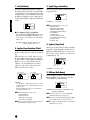
EXIT
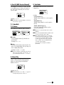
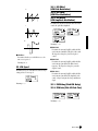
Demo Song Selection
While the Demo song is playing back, you can select the particular Demo song that you wish to hear.
Enter the desired Demo song category from the numeric keypad to call up the song.
7
8
9
PRESET
PIANO
4
ORGAN
5
GUITAR
6
DRUM/PERC
USER
BASS
1
STRINGS
2
BRASS
3
REED/PIPE
0
SYN LEAD
SYN PAD
ENTER
SYN COMP
CHROMATIC KEYBOARD
PERCUSSION
CATEGORY
SEARCH
DRUM
SE
GM XG
OTHER
Select the
category
EXIT
For example, you can play the piano song by pressing button 7 (PIANO) in the numeric keypad. If you don’t select a
particular song, an ensemble (OTHER) song will play back automatically.
n When there are several Demo songs contained in one category, you can select from among the available songs by using the
[DEC/NO] and [INC/YES] buttons.
16
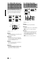
Basics Section
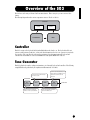
Overview of the S03
The S03 has a wide variety of advanced and convenient features. This section gives you an overview of these
features.
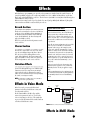
The following diagram shows the various component sections or “blocks” of the S03.
Controller
keyboard
controllers
Tone Generator
Effect
Controller
This block consists of the keyboard, Pitch Bend and Modulation wheels and so on. The keyboard itself doesn’t
generate sounds, but instead sends note, velocity and other information to the S03’s tone generator section for the
notes you play. The controllers also send non-note performance data. Information from the keyboard and
controllers can be transmitted to other external MIDI devices through the MIDI OUT connector.
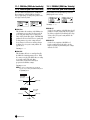
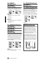
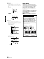
Tone Generator
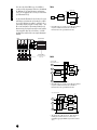
This block plays back sounds according to information received from the keyboard and controllers. The following
example illustrates the path taken by the signal from an Element in the Voice Mode.
Controls the pitch of each Element output
from the OSC section.
Controls the output level (amplitude) of each
Element output from the FILTER section. The
signals are then sent at this level to the
Effects Units.
Tone Generator
OSC
(Oscillator)
PITCH
Outputs the waveform of each Element.
Each Voice consists of up to four Elements.
FILTER
AMP
(Amplitude)
To Effects Units
Changes the tonal quality of each Element
output from the PITCH section.
17
Basics Section
About the Tone Generator
The tone generator of the S03 utilizes the sophisticated AWM2 system.
AWM2 (Advanced Wave Memory 2) is a synthesis system based on the use of sampled waveforms, and is used in
many Yamaha synthesizers. For extra realism, each AWM2 Voice uses multiple samples of a real instrument’s
waveform. Furthermore, a wide variety of envelope generator, filter, modulation, and other parameters can be
applied to the basic waveform.
n AWM2 is not just limited to conventional pitched instruments (Normal Voices), but also produces various drum and percussion
instruments (Drum Voices). For details about Normal and Drum Voices, see page 26.
Maximum Polyphony
The maximum polyphony of the S03 is 64 notes. However, the actual note polyphony will vary depending on the
number of Elements in the Voice. To calculate the actual polyphony, divide the total polyphony of 64 by the number
of Elements in the Voice. For instance, if a Voice consists of two Elements, the maximum note polyphony for the
Voice is 32.
Effects
The effects can be used to change or enhance the sound of a Multi or Voice.
These include the effects of the Reverb section (11 types) for adding ambient after-tones to the sound, the Chorus
section (11 types) that add animation and depth, and the Variation section (42 types) which features a wealth of
additional effects.
n For more details about the effects, see page 53.
18
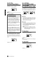
Basics Section
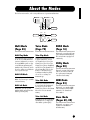
About the Modes
The S03 has various modes, each covering a different set of operations and functions.
Voice Mode
Multi Mode
Multi Play Mode
Multi Edit Mode
Multi Job Mode
Voice Play Mode
Voice Edit Mode
Voice Job Mode
MODE
MULTI
VOICE
DEMO
DEMO Mode
UTILITY
MIDI
Utility Mode
MIDI Mode
EDIT
JOB
STORE
Store Mode
COMPARE
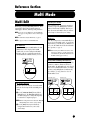
Multi Mode
(Page 55)
Voice Mode
(Page 70)
DEMO Mode
(Page 16)
Multi Play Mode
Voice Play Mode
Select this mode when you want to
use the S03 as a multi-timbral tone
generator. In this mode, you can use
an external MIDI sequencer to play
several different instrument parts
simultaneously. This mode can also
be used to combine several different
Voices together in a layer.
Normal Voices and Drum Voices can
be played in this mode. You can
select from the Preset Voices (128
Normal Voices), User Voices (128
Normal Voices plus two Drum Kits)
and XG Voices (480 Normal Voices
plus 20 Drum Kits). The S03 also
features a convenient Category
Search function that lets quickly
select a Voice according to its
instrument type.
In this mode, you can play the Demo
songs contained in internal memory.
The various Demo songs play back
continuously.
Multi Edit Mode
In this mode, you can edit and create
Multis. You can save up to 32 Multis
to internal memory.
Multi Job Mode
In this mode, you can copy and
initialize Multis, and perform other
similar operations (Jobs).
Voice Edit Mode
Normal Voices and Drum Voices can
be created and edited in this mode.
You can save up to 128 edited
Normal Voices and two edited Drum
Kits as User Voices in internal
memory.
Voice Job Mode
In this mode, you can copy Elements
and initialize Voices, and perform
other similar operations (Jobs).
Utility Mode
(Page 90)
This mode contains global settings
related to the entire system of the
S03, such as master tuning and
controller-related settings.
MIDI Mode
(Page 93)
In this mode, you can make MIDIrelated settings, such as the MIDI
transmit/receive channels and
device number.
Store Mode
(Pages 69, 89)
In this mode, you can store your
original Voices and Multis to
internal memory.
19
Basics Section
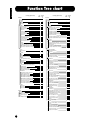
Function Tree chart
LCD Display (parameter name)
Multi Edit
Common
GENERAL
Name
Total Vol (Total Volume)
Transpose
EFFECT
RevEF (Reverb Effect Type)
Reverb Parameters
Rev Return (Reverb Return)
Reverb Pan
ChoEF (Chorus Effect Type)
Chorus Parameters
Cho Return (Chorus Return)
Chorus Pan
SndCho Rev (Send Chorus to Reverb)
VarEF (Variation Effect Type)
Variation Parameters
VarConnect (Variation Connection)
Var Return (Variation Return)
Var Pan
SndVar Rev (Send Variation to Reverb)
SndVar Rev (Send Variation to Chorus)
MW VarCtl (MW Variation Effect Control Depth)
AC1VarCtl (AC1 Variation Effect Control Depth)
Part
VOICE
Voice Selection
MIX
Volume
Pan
NtLmt-H (Note Limit Low/High)
VelLmt-L (Velocity Limit Low/High)
GENERAL
Rcv Ch (MIDI Receive Channel)
NoteShift/Detune
Mono/Poly
Part Mode
TONE
VelSnsDpt/Ofs (Velocity Sensitivity Depth/Offset)
Cutoff/Resonance
Attack/Decay/Releas Tm (Attack/Decay/Release Time)
PEG L/Tm (PEG Level/Time)
Vib Rate/Depth/Delay (Vibrato Rate/Depth/Delay)
CONTROLLER
Porta Sw/Time (Portamento Switch/Time)
PB Range (Pitch Bend Range)
MW FltCtl (MW Filter Control)
MW PMod (MW Pitch Modulation Depth)
MW FMod (MW Filter Modulation Depth)
MW AMod (MW Amplitude Modulation Depth)
AC1 CC No (AC1 Control Change Number)
AC1FltCtl (AC1 Filter Control)
AC1 FMod (AC1 Filter Modulation Depth)
AC1 AMod (AC1 Amplitude Modulation Depth)
EFFECT
ReverbSend
ChorusSend
Var Send (Variation Send)
Multi Job
Init (Initialize)
CpyVar (Copy Variation Effect)
CpyCtl (Copy Controller)
CpyPart (Copy Part)
BlkDmp (Bulk Dump)
20
LCD
PAGE
Owner's Manual
Page
56
1
2
3
56
56
56
4
5
6
7
8
9
10
11
12
13
14
15
16
17
18
19
20
21
56
56
56
57
57
57
57
57
57
57
57
58
58
58
58
58
58
59
1
59
2
3
4
5
60
60
60
60
6
7
8
9
61
61
61
61
10
11
12
13
14
62
63
63
64
64
15
16
17
18
18
18
19
20
21
21
65
65
65
65
65
65
66
66
66
66
22
23
24
66
66
67
1
2
3
4
5
67
68
68
68
68
68
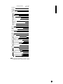
LCD Display (parameter name)
Voice Edit
Common
GENERAL
Name
Total Vol/Lvl (Total Volume/Level)
Mono/Poly
VelSnsDpt/Ofs (Velocity Sensitivity Depth/Offset)
CONTROLLER
Porta Sw/Time (Portamento Switch/Time)
PB Range (Pitch Bend Range)
MW FltCtl (MW Filter Control)
MW PMod (MW Pitch Modulation Depth)
MW FMod (MW Filter Modulation Depth)
MW AMod (MW Amplitude Modulation Depth)
AC1FltCtl (AC1 Filter Control)
AC1 FMod (AC1 Filter Modulation Depth)
AC1 AMod (AC1 Amplitude Modulation Depth)
EFFECT
ReverbSend
ChorusSend
SndCho Rev (Send Chorus to Reverb)
VarEF (Variation Effect Type)
Variation Parameters
MW VarCtl (MW Variation Effect Control Depth)
AC1 VarCtl (AC1 Variation Effect Control Depth)
Element
OSC/MIX (Oscillator/Mixer)
Element Sw (Element Switch)
Wave Selection
Level
Pan
NtLmt-L/H (Note Limit Low/High)
VelLmt-L/H (Velocity Limit Low/High)
PITCH
NoteShift/Detune
PchSclSns (Pitch Scale Sensitivity)
PchSclCN (Pitch Scale Center Note)
PEG R (PEG Rate)
PEG L (PEG Level)
PEGSclSns (PEG Scale Sensitivity)
PEGSclCN (PEG Scale Center Note)
PEGRtVel (PEG Rate Velocity)
PEGLvlVel (PEG Level Velocity)
FILTER
Cutoff/Resonance
CutoffVel (Cutoff Velocity Sensitivity)
ResoVel (Resonance Velocity Sensitivity)
FltSclFlag (Filter Scale Flag)
Flt BP1~4 (Filter Scale Break Point 1~4)
Flt Ofs1~4 (Filter Scale Offset 1~4)
FltSclSns (Filter Scale Sensitivity)
FltSclVel (Filter Scale Velocity Sensitivity)
FEG R (FEG Rate)
FEG L (FEG Level)
FEGSclSens (FEG Scale Sensitivity)
FEGAtkVel (FEG Attack Velocity)
FEGOthVel (FEG Other Velocity)
AMP (Amplitude)
AEG R (AEG Rate)
AEG L (AEG Level)
AEGSclSens (AEG Scale Sensitivity)
AEGLvlVel (AEG Level Velocity Sensitivity)
AEGAtkVel (AEG Attack Velocity Sensitivity)
LvlSclFlag (AEG Level Scale Flag)
Lvl BP1~4 (Level Break Point 1~4)
Lvl Ofs1~4 (Level Offset 1~4)
LvlSclSens (Level Scale Sensitivity)
KeyonDelay
LFO (Low Frequency Oscillator)
LFO Wave
LFO Phase (LFO Phase Initialize)
LFO Speed
LFO PMod (LFO Pitch Modulation)
LFO FMod (LFO Filter Modulation)
LFO AMod (LFO Amplitude Modulation)
PLFODelay (Pitch LFO Delay)
PLFO Fade (Pitch LFO Fade Time)
LCD
PAGE
Owner's Manual
Page
71
1
2
3
4
71
71
71
72
5
6
7
8
8
8
9
10
10
72
72
72
72
72
72
72
72
72
11
12
13
14
15
16
17
72
72
72
72
72
72
72
1
2
3
4
5
6
73
73
73
73
73
74
7
8
8
9
10
11
11
12
12
74
74
74
75
75
76
76
76
76
13
14
14
15
16
17
18
18
19
20
21
22
22
77
77
77
77
78
78
78
78
79
79
79
80
80
23
24
25
26
26
27
28
29
30
31
80
80
81
81
81
81
81
82
82
82
32
32
33
34
34
34
35
35
82
82
83
83
83
83
83
83
Voice Job
Init (Initialize)
CpyElm (Copy Element)/CpyKey (Copy Drum Key)
BlkDmp (Bulk Dump)
LCD
PAGE
Owner's Manual
Page
84
1
2
85
85
1
2
3
4
5
85
85
85
85
86
6
86
7
86
8
86
9
10
87
87
1
2
3
87
88
88
88
DEMO Mode
Demo Song Play
16
16
Utility Mode
TG (Tone Generator)
MasterTune
KEYBOARD
Kbd Trans (Keyboard Transpose)
Vel Curve (Velocity Curve)
Fixed Vel (Fixed Velocity)
CONTROLLER
MWTxCtlNo (MW Transmit Control Number)
FCTxCtlNo (Foot Controller Transmit Control Number)
FSTxCtlNo (Footswitch Transmit Control Number)
Ctl Reset (Controller Reset)
AC1 CC No (AC1 Control Change Number)
EFFECT
V EfBypass (Voice Effect Bypass)
90
MIDI Mode
MIDI CHANNEL
Device No (Device Number)
Local Sw (Local On/Off Switch)
Rcv Ch (Voice Mode MIDI Receive Channel)
Trans Ch (MIDI Transmit Channel)
MIDI FILTER
RxPgmChng (Receive Program Change On/Off)
RxBankSel (Receive Bank Select On/Off)
TxPgmChng (Transmit Program Change On/Off)
TxBankSel (Transmit Bank Select On/Off)
Thru Port
Basics Section
LCD Display (parameter name)
Voice Edit (Drum)
Common
GENERAL
Name
OrgKt (Original Kit)
Key
OSC/MIX (Oscillator/Mixer)
Level
Pan
Alt.Group (Alternate Group)
Key Assign
RxNoteOff/On (Receive Note On/Off)
PITCH
PitchCors/Fine (Pitch Coarse/Fine)
FILTER
Cutoff/Resonance
AMP (Amplitude)
EG Attack/Decay1/Decay2(EG Attack/Decay1/Decay2 Rate)
EFFECT
ReverbSend
ChorusSend
1
90
2
3
3
90
90
90
4
4
5
6
7
91
91
91
91
92
8
92
1
2
3
4
93
93
94
94
5
5
6
6
7
94
94
94
94
94
93
n For details about the Multi Store procedure, see page 69;
for details about the Voice Store procedure, see page 89.
21
Basics Section
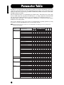
Parameter Table
The numbers in each column indicate the display PAGE corresponding to the parameter at left (with the exception of the
column on the far right, which indicates the corresponding manual page). For example, you can see that the Reverb Send
parameter is found on three separate display pages: PAGE 22 of Multi Part Edit, PAGE 11 of Normal Voice Common Edit,
and PAGE 9 of Drum Voice Key Edit.
This table is helpful in locating the corresponding display pages in different modes. This is handy when you want to make
the same or similar settings to the same parameter in a different mode — for example, setting the Reverb Send in the Multi
mode to the same value as Reverb Send in the Voice mode. It’s also handy for cross-checking same parameters for
programming complex sound changes — such as setting the Voice’s Filter Cutoff to a certain value, then going to Cutoff in
the Multi mode and tweaking it further.
Since the owner’s manual page reference is also provided, you can quickly find the corresponding explanation by checking
the currently selected mode and PAGE number on the S03, and referring to this table.
n When the parameter is the same for both the Voice mode and Multi mode, the manual page reference is generally for the
explanation in the Multi mode.
Multi Edit
Parameter Type
LCD Display (parameter name)
GENERAL
Name
Total Vol (Total Volume)
Total Lvl (Level)
Transpose
Rcv Ch (MIDI Receive Channel)
NoteShift/Detune
Mono/Poly
Part Mode
OrgKt (Original Kit)
RevEF (Reverb Effect Type)
Reverb Parameters
Rev Return (Reverb Return)
Reverb Pan
ChoEF (Chorus Effect Type)
Chorus Parameters
Cho Return (Chorus Return)
Chorus Pan
SndCho Rev (Send Chorus to Reverb)
VarEF (Variation Effect Type)
Variation Parameters
VarConnect (Variation Connection)
Var Return (Variation Return)
Var Pan
Snd Var Rev (Send Variation to Reverb)
Snd Var Cho (Send Variation to Chorus)
MW VarCtl (MW Variation Effect Control Depth)
AC1VarCtl (AC1 Variation Effect Control Depth)
ReverbSend
ChorusSend
Var Send (Variation Send)
V EfBypass (Voice Effect Bypass)
Voice Selection
Volume
Pan
NtLmt-H (Note Limit Low/High)
VelLmt-L (Velocity Limit Low/High)
VelSnsDpt/Ofs (Velocity Sensitivity Depth/Offset)
Cutoff/Resonance
Attack/Decay/Release Tm (Attack/Decay/Release Time)
PEG L/Tm (PEG Level/Time)
Vib Rate/Depth/Delay (Vibrato Rate/Depth/Delay)
Porta Sw/Time (Portamento Switch/Time)
PB Range (Pitch Bend Range)
MW FltCtl (MW Filter Control)
MW PMod (MW Pitch Modulation Depth)
MW FMod (MW Filter Modulation Depth)
MW AMod (MW Amplitude Modulation Depth)
AC1 CC No (AC1 Control Change Number)
AC1FltCtl (AC1 Filter Control)
AC1 FMod (AC1 Filter Modulation Depth)
AC1 AMod (AC1 Amplitude Modulation Depth)
MWTxCtlNo (MW Transmit Control Number)
FCTxCtlNo (Foot Controller Transmit Control Number)
FSTxCtlNo (Footswitch Transmit Control Number)
Ctl Reset (Controller Reset)
EFFECT*
VOICE
MIX
TONE
CONTROLLER*
22
Common
Part
1
2
Voice Edit
Common
Element/Key
Normal
Drum
Normal
Drum
1
1
2
2
3
1
UTILITY
MIDI
3
6
7
8
9
3
7
3
2
4
5
6
7
8
9
10
11
12
13
14
15
16
17
18
19
20
21
13
14
15
22
23
24
16
17
11
12
9
10
8
1
2
3
4
5
10
11
12
13
14
15
16
17
18
18
18
19
20
21
21
4
5
6
2
13
7
4
5
6
7
8
8
8
7
9
10
10
4
4
5
6
Owner's
Manual
Page
56, 71
56, 71
71, 73, 85
56
61, 94
61, 74
61, 71
61
85
56
56
56
57
57
57
57
57
57
57
57
58
58
58
58
58
58
66
66
66
67
92
59
60
60, 73, 85
60, 73
60, 74
62
63, 77, 86
63
64
64
65
65
65
65
65
65
66, 92
66
66
66
91
91
91
91
LCD Display (parameter name)
OSC/MIX (Oscillator/Mixer)
Element Sw (Element Switch)
Wave Selection
Level
Alt.Group (Alternate Group)
Key Assign
RxNoteOff/On (Receive Note On/Off)
NoteShift/Detune
PchSclSns (Pitch Scale Sensitivity)
PchSclCN (Pitch Scale Center Note)
PEG R (PEG Rate)
PEG L (PEG Level)
PEGSclSns (PEG Scale Sensitivity)
PEGSclCN (PEG Scale Center Note)
PEGRtVel (PEG Rate Velocity)
PEGLvlVel (PEG Level Velocity)
PitchCors/Fine (Pitch Coarse/Fine)
Cutoff/Resonance
CutoffVel (Cutoff Velocity Sensitivity)
ResoVel (Resonance Velocity Sensitivity)
FltSclFlag (Filter Scale Flag)
Flt BP1~4 (Filter Scale Break Point 1~4)
Flt Ofs1~4 (Filter Scale Offset 1~4)
FltSclSns (Filter Scale Sensitivity)
FltSclVel (Filter Scale Velocity Sensitivity)
FEG R (FEG Rate)
FEG L (FEG Level)
FEGSclSens (FEG Scale Sensitivity)
FEGAtkVel (FEG Attack Velocity)
FEGOthVel (FEG Other Velocity)
AEG R (AEG Rate)
AEG L (AEG Level)
AEGSclSens (AEG Scale Sensitivity)
AEGLvlVel (AEG Level Velocity Sensitivity)
AEGAtkVel (AEG Attack Velocity Sensitivity)
LvlSclFlag (AEG Level Scale Flag)
Lvl BP1~4 (Level Break Point 1~4)
Lvl Ofs1~4 (Level Offset 1~4)
LvlSclSens (Level Scale Sensitivity)
KeyonDelay
EG Attack/Decay1/Decay2(EG Attack/Decay1/Decay2 Rate)
LFO Wave
LFO Phase (LFO Phase Initialize)
LFO Speed
LFO PMod (LFO Pitch Modulation)
LFO FMod (LFO Filter Modulation)
LFO AMod (LFO Amplitude Modulation)
PLFODelay (Pitch LFO Delay)
PLFO Fade (Pitch LFO Fade Time)
MasterTune
Kbd Trans (Keyboard Transpose)
Vel Curve (Velocity Curve)
Fixed Vel (Fixed Velocity)
Device No (Device Number)
Local Sw (Local On/Off Switch)
Rcv Ch (Voice Mode MIDI Receive Channel)
Trans Ch (MIDI Transmit Channel)
RxPgmChng (Receive Program Change On/Off)
RxBankSel (Receive Bank Select On/Off)
TxPgmChng (Transmit Program Change On/Off)
TxBankSel (Transmit Bank Select On/Off)
Thru Port
PITCH
FILTER
AMP (Amplitude)
LFO (Low Frequency Oscillator)
TG (Tone Generator)
KEYBOARD
MIDI CHANNEL
MIDI FILTER
Common
Part
7
11
Voice Edit
Common
Element/Key
Normal
Drum
Normal
Drum
1
2
3
3
4
5
7
8
8
9
10
11
11
12
12
6
13
7
14
14
15
16
17
18
18
19
20
21
22
22
23
24
25
26
26
27
28
29
30
31
8
32
32
33
34
34
34
35
35
UTILITY
MIDI
1
2
3
3
1
2
3
4
5
5
6
6
7
Basics Section
Multi Edit
Parameter Type
Owner's
Manual
Page
73
73
85
85
85
86
61, 74
74
74
75
75
76
76
76
76
86
63, 77, 86
77
77
77
78
78
78
78
79
79
79
80
80
80
80
81
81
81
81
81
82
82
82
86
82
82
83
83
83
83
83
83
90
90
90
90
93
93
94
94
94
94
94
94
94
n For parameters in different modes having the same name, the available parameter values and settings for that parameter may
differ depending on the mode. Refer to each parameter explanation for details.
n For details on parameters for the Reverb, Chorus and Variation effects, refer to the separate Data List.
n For information on the Job pages, refer to the Function Tree chart (page 20).
*
In the Multi mode, the Voice Common Effect/Controller settings are ignored, and the Multi settings become effective. The Variation
Effect/Controller settings of the Voice mode can be copied to the Multi mode by using the Multi Job function (page 68).
23
Basics Section
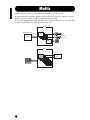
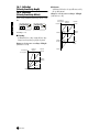
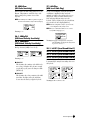
Multis
A Multi consists of up to 16 Parts, each of which can play a Normal Voice or Drum Voice Part.
By assigning different Voices and MIDI channels to each part, and by using a sequencer or computer for song data
playback, you can have a complete ensemble of 16 independent instrument sounds.
You can also play Multis from the keyboard. This allows you to set up layers of different Voices, or special key splits
in which your right and left hands can play separate Voices (page 41).
Multi
Part 1~16
External MIDI sequencer
MIDI CH
1~16
CH1
Different Voice
for each part
Song File
CH16
Multi
Part 1~16
Two Layered
Voices
24
A Voice is a single instrument sound, created by using the Elements and setting various parameters. In the Voice
Play mode, you can select and play any of these Voices. In the Multi Play mode, you assign a different Voice to each
part and use an external sequencer to play several Voices simultaneously.
Voices are stored in the internal memory (PRESET, USER, GM/XG).
Multi Play Mode
Voice Play Mode
Controllers
Controllers
External MIDI sequenser
Tone Generator
Voice
Tone Generator
Multi
Part
Voice
1
2
PR PR
001 002
Playing a Voice
4
5
PR
003
XG
001
XG
002
6
7
XG US
003 001
8
16
US
002
PR
016
Playing a Multi
Preset
128 Preset Voice
PR001~128
3
GM/XG Voice
480
NormalVoice
User
128 User Voice
US001~128
2 User
Drum Voice
20 Drum Voice *
* Drum Voices XG121~128 are not of the GM/XG set, but are original drum kits specifically programmed for the S03.
25
Basics Section
Voices
Basics Section
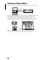
Overview of Voices/Waves
Each Voice can consist of up to four Elements. Each Element itself is a high-quality waveform or instrument sound.
Voice
Element 1~4
Element
Wave form
AWM2: 453 Prest waveforms
There are two Voice types: Normal Voices and Drum Voices. Normal Voices are mainly pitched instrument sounds
that can be played over the range of the keyboard. Drum Voices are mainly percussion/drum sounds that are
assigned to individual notes on the keyboard. The Drum Voices also include special sound effects.
In general, a Voice (containing up to four Elements) can be played across the entire range of the keyboard. However,
this can be changed; the actual key range for the Voice is determined by the Note Limit parameters (page 73).
Nomal Voice
Drum Voice
Voice
Element 1~4
Individual drum
sounds (different
for each key)
n A total of 480 (XG) and 128 (Preset) Normal Voices plus 20 Drum Voices are available as presets. You can create and store your
own original Voices; the S03 has User memory space for 128 User Normal Voices and two User Drum Voices.
26
Waves (or waveforms) are the basic sonic building blocks, and are used as Elements in making up a Voice. A total of
453 high-quality preset Waves are available. As shown in the following illustration, when creating a Voice, you can
select the Wave to be used as an Element and then set its level, pitch, tone and other parameters.
Wave 1~453
Element 1
Element 2
Element 3
Element 4
C-2
G8
Voice
27
Basics Section
Waves
Basics Section
Basic Operations
In this section, you’ll learn the fundamental operations of the S03.
Selecting a Mode
There are several operation modes — the Multi Play
mode, Voice Play mode, etc. — each of which enables
you to work efficiently with the S03’s various
functions.
n For an overview of the various modes, see page 19.
There are separate Play modes for Multis and Voices.
To enter each of these modes, use the appropriate
MODE button ([Multi] for Multi Play mode, [VOICE]
for Voice Play mode).
There are also separate Edit and Job modes for Multis
and Voices. To enter the Edit or Job mode, simply press
the [EDIT] or [JOB] button while in each respective
Play mode.
Similarly, pressing the [STORE] button in the Multi or
Voice mode takes you into the Store mode where you
can store Multis or Voices.
In addition the modes mentioned above, there is also a
Utility mode, which is for making global settings to the
instrument, and the MIDI mode, which contains MIDIrelated settings. Finally, there is the Demo mode,
which allows you to play back the Demo songs.
To select these, press the [UTILITY] button for the
Utility mode, the [MIDI] button for the MIDI mode
and the [DEMO] button for the Demo mode.
1
2
7
MODE
MULTI
UTILITY
VOICE
DEMO
6
EDIT
JOB
1 Multi Play Mode (Page 37)
Press the [MULTI] button (the LED lights) to enter the
Multi Play mode. To exit to another mode, simply
press the respective button for that mode.
PAGE
OCTAVE
2 Voice Play Mode (Page 33)
Press the [VOICE] button (the LED lights) to enter the
Voice Play mode. To exit to another mode, simply press
the respective button for that mode.
PAGE
Edit Modes
There are also separate Edit and Job modes for each
Play mode. The [EDIT] lamp lights along with the
appropriate Play mode lamp, [MULTI] or [VOICE].
3 Multi Edit Mode (Page 55)
PAGE
1
28
OCTAVE
4
GrandPno
XG001
PART ELEM KEY
OCTAVE
STORE
COMPARE
3
Init Mlt
P
MLT01
PART ELEM KEY
Press the [EDIT] button in the Multi Play mode. To
exit to another mode, simply press the respective
button for that mode. Press the [EXIT] button to
return to the Multi Play mode.
MIDI
5
Play Modes
8
Init Mlt
P
Name
PART ELEM KEY
3 Voice Edit Mode (Pages 47, 70)
PAGE
1
GrandPno
E
XG001
PART ELEM KEY
OCTAVE
Job Modes
Each Play mode features a separate Job mode. You can
select the desired Job mode when the appropriate Play
mode lamp, [MULTI] or [VOICE], is lit.
UTILITY
PART ELEM KEY
OCTAVE
6 MIDI Mode (Page 93)
Press the [MIDI] button to enter the MIDI mode. To
exit to another mode, simply press the respective
button for that mode. If one of the Play mode lamps
([MULTI] or [VOICE]) is lit, the corresponding Play
mode is still active, even while entering this mode. An
arrow appears in the lower left of the LCD, pointing to
“MIDI” on the panel, indicating the MIDI mode.
UTILITY
4 Multi Job Mode (Page 67)
MasterTune
1
+0000
PAGE
MIDI
Basics Section
Press the [EDIT] button in the Voice Play mode. To
exit to another mode, simply press the respective
button for that mode. Press the [EXIT] button to
return to the Voice Play mode.
Device No
1
all
PAGE
MIDI
PART ELEM KEY
OCTAVE
Press the [JOB] button in Multi Play mode. To exit to
another mode, simply press the respective button for
that mode. Press the [EXIT] button to return to the
Multi Play mode.
PAGE
1
Init
multi
PART ELEM KEY
OCTAVE
4 Voice Job Mode (Page 87)
Press the [Job] button in Voice Play mode. To exit to
another mode, simply press the respective button for
that mode. Press the [EXIT] button to return to the
Voice Play mode.
PAGE
1
Init
voice
PART ELEM KEY
OCTAVE
Other Modes
5 Utility Mode (Page 90)
Press the [UTILITY] button to enter the Utility Mode.
To exit to another mode, simply press the respective
button for that mode. If one of the Play mode lamps
([MULTI] or [VOICE]) is lit, the corresponding Play
mode is still active, even while entering this mode. An
arrow appears in the upper left of the LCD, pointing to
“UTILITY” on the panel, indicating the Utility mode.
7 Demo Mode (Page 16)
Press the [DEMO] button (the LED lights) to enter the
Demo mode. To exit from the Demo mode and switch
to the Multi or Voice Play mode, press the [EXIT],
[MULTI] or [VOICE] button.
At the “Demo” screen, any data in the instrument’s User
Voice memory will be overwritten by the data for the
demo song. Important data should be saved to the
external MIDI device or computer beforehand.
At the “DEMO” screen, the Master Tune parameter (in
Utility) will be overwritten and set to “0.”
8 Store Mode (Pages 69, 89)
Pressing the [STORE] button in the Multi or Voice
mode enters the Store mode where you can store
Multis or Voices. The Play mode lamp ([MULTI] or
[VOICE]) remains lit, even when entering this mode.
To exit to another mode, simply press the
corresponding mode’s button. Pressing the [EXIT]
button exits from the Store mode.
Store
MLT01
PAGE
PART ELEM KEY
OCTAVE
29
Basics Section
Selecting a Screen
[E]/[F] buttons
You can switch between screens by using the [▲]/[▼],
[E]/[F], [+]/[–] and [EXIT] buttons.
Some of the display pages have multiple “screens.”
These are indicated by special arrow marks in the top
right of the LCD (see below). Use the [E]/[F]
buttons to select these pages.
When the first screen of a mulitple-page set is called up,
the arrow points to the right (fi), indicating further
screens are available. When a page in the middle of the
set is called up, arrows point in both directions (‹ fi),
indicating you can select either the next or previous
screens. When the last screen is called up, the arrow
points to the left (‹), indicating no further screens are
available.
For certain parameters (such as Voice Name, etc.),
these buttons are used to move the cursor position in
the display.
[▲]/[▼] buttons
Many of the displays consist of different screens. Use
the [▲]/[▼] buttons to select the various screens.
Previous screen (PAGE)
DATA
DEC NO
INC YES
Decay Tm
12
1
+00
Next screen (PAGE)
PAGE
When selecting the various display pages, an arrow
appears at the right of the LCD, indicating the
parameter type in the printed list on the panel.
For example, if the display for the Total Volume
parameter in the Multi Edit mode is called up, the
arrow in the LCD indicates that this parameter belongs
to the General type.
VOICE
Total Vol
2 P
127
PAGE
DATA
DEC NO
INC YES
Selects the
previous screen.
Selects the
next screen.
[+]/[–] buttons
MIX
GENERAL
PART ELEM KEY
PART ELEM KEY
OCTAVE
TONE
CONTROLLER
OCTAVE
EFFECT
In the example below, the display for the (Element)
Cutoff parameter in the Voice Edit mode is shown, and
the arrow indicates that this parameter belongs to the
Filter type.
In the Multi Edit mode, these buttons are used to select
each part. To select the Common parameters, press
both buttons simultaneously. In the Voice Edit mode,
these buttons are used to select each Element. To
select the Common parameters, press both buttons
simultaneously.
PART ELEMENT KEY
Cutoff
13 E
2047
PAGE
OCTAVE
30
PART ELEM KEY
VOICE
OSC MIX
MIX
PITCH
GENERAL
FILTER
TONE
AMP
CONTROLLER
LFO
EFFECT
EFFECT
MUTE
COMMON
n For details on the parameters and page configurations of
the Multi Edit and Voice Edit modes, refer to the relevant
mode explanations in the Reference section of this
manual.
Entering Data
Press the [EXIT] button to move up (exit) in the
hierarchical structure and return to the previous
screen.
Use the [INC/YES] and [DEC/NO] buttons to
increment through the values, or input the value
directly by using the numeric keypad and the [ENTER]
button.
For certain parameters (such as Voice Name, etc.)
which have more than one value to be set, use the
[E]/[F] buttons to move the cursor position in the
display, then set the value accordingly.
7
8
9
PIANO
4
ORGAN
5
GUITAR
6
BASS
1
STRINGS
2
BRASS
3
REED/PIPE
0
SYN LEAD
SYN PAD
ENTER
SYN COMP
CHROMATIC KEYBOARD
PERCUSSION
EXIT
n Depending on the particular operation, the [EXIT]
button performs other functions as well. These alternate
functions are indicated in the appropriate sections of the
manual.
[INC/YES] and [DEC/NO]
buttons
These are used to change the value of the currently
selected parameter. You can use the [INC/YES] button
to increment a parameter setting by one step, or the
[DEC/NO] button to decrement it. If you hold down
either button, the value is continuously changed. You
can also use these buttons to answer “YES” or “NO”
when a confirmation message is displayed.
DATA
DEC NO
INC YES
31
Basics Section
[EXIT] button
Basics Section
Numeric keypad, [ENTER]
button
You can specify the value for the selected parameter by
using the numeric keypad, then actually set that value
by pressing the [ENTER] button. For example, to set a
value of “100,” press (in order) the numeric keypad
buttons [1], [0], and [0]. (The parameter indicator
flashes.) Finally, press the [ENTER] button to set the
value.
7
8
9
PIANO
4
ORGAN
5
GUITAR
6
BASS
1
STRINGS
2
BRASS
3
PAGE
PART ELEM KEY
100
OCTAVE
The displayed value flashes.
SYN PAD
ENTER
REED/PIPE
0
SYN LEAD
SYN COMP
CHROMATIC KEYBOARD
PERCUSSION
Specify the value.
Types of Parameters (Absolute and
Relative)
There are many ways to set parameters. Some
parameters require you to directly enter numerical
settings or alphabetic characters. With others, you
can choose from a number of available settings.
Furthermore, some types of parameters are
“absolute” whereas others are “relative.”
For example, the absolute parameter in the following
illustration can be set to either “mono” or “poly.”
For other absolute parameters such as Volume, the
setting can be any value between zero and 127. The
Volume setting has a linear, one-to-one relationship
with the actual volume, as shown in the graph on the
left.
However, relative parameters do not follow the same
relationship. The graph on the bottom shows the
role of the Velocity Offset parameter. The value you
have set here, known as an “offset,” is added to, or
subtracted from, the actual value. With Velocity
Offset, the specified offset value is added to, or
subtracted from, the actual velocity of the notes you
play on the keyboard. Sometimes, these types of
relative parameters are set as a percentage.
Set the value.
Total Vol
2 E
127
PAGE
Moving the Cursor Position
For certain parameters, such as Voice Name and
others, the [E]/[F] buttons are used to move the
cursor position in the display. (The selected character
flashes.) Move the cursor to the desired position, then
set the value.
DATA
DEC NO
PART ELEM KEY
OCTAVE
Mono/Poly
3 E
poly
PAGE
PART ELEM KEY
OCTAVE
VelSnsOfs
4 E
064
PAGE
PART ELEM KEY
OCTAVE
1. Total Volume (absolute)
Volume
INC YES
0
127
2. Velocity offset (relative)
Offset
+64
Offset added (+10)
Actual velocity
Offset subtracted (–10)
0
Volume
–64
32
Basics Section
Playing the S03
Playing the Voices
You can freely select and play Voices from the PRESET, USER and GM/XG memory groups, as explained below.
n Details about voice, see page 25.
n The user memory can contain up to 128 Normal Voices and 2 Drum Voices.
1
PHONES
OUTPUT
L MONO
R
DC IN
STANDBY
ON
FOOT
CONTROLLER
FOOT
SWITCH
TO HOST
HOST SELECT
IN
MIDI
OUT
UTILITY MIDI
MULTI PART
VOICE COMMON
VOICE
UTILITY
MUSIC SYNTHESIZER
MIDI
MODE
MULTI
VOICE
PART ELEMENT KEY
DEMO
TG
PITCH
KEYBOARD
FILTER
MIDI CHANNEL
TONE
AMP
MIDI FILTER
CONTROLLER
LFO
CONTROLLER
EFFECT
EFFECT
EFFECT
UP
8
9
PRESET
PIANO
4
ORGAN
5
GUITAR
6
DRUM/PERC
USER
BASS
1
STRINGS
2
BRASS
3
REED/PIPE
0
SYN LEAD
SYN PAD
ENTER
SYN COMP
CHROMATIC KEYBOARD
PERCUSSION
CATEGORY
SEARCH
DRUM
7
MUTE
ELEMENT
OSC MIX
MIX
GENERAL
COMMON
DATA
UTILITY
MIDI
EDIT
JOB
DEC NO
INC YES
OCTAVE
DOWN
3
THRU
EDIT
VOLUME
2
SE
GM XG
STORE
COMPARE
OTHER
EXIT
4
1 Press the [VOICE] button.
Press the [VOICE] button (the LED lights) to enter the
Voice Play mode. The following display appears.
PAGE
GrandPno
XG001
Preset Voice
1~128
CATEGORY
SEARCH
DRUM
PRESET
PART ELEM KEY
OCTAVE
DRUM/PERC
USER
Now, play the Voice (indicated in the display) from the
keyboard.
2 Press a MEMORY button
to select a Voice Memory.
User Voice
1~128
SE
GM XG
OTHER
GM/XG Voice
GM Bank
Other Bank
........
There are three different memory sections for the
Normal Voices: PRESET, USER, and GM/XG. The
various Voices are assigned to each memory section as
shown below. The GM/XG Voices are divided into
several different banks.
33
Basics Section
The Drum Voices are stored in separate areas of the
User and GM/XG memory sections.
3 Select a Voice number.
• To call up the User Drum memory (USDR1/
USDR2):
Press the [USER] button while holding down the
[DRUM] button.
Selecting with the [INC/YES] and
[DEC/NO] buttons
• To call up the GM/XG Drum memory
• To call up the XG SFX Kit memory
Press the [GM/XG] button while holding down the
[DRUM] button.
First, press the [ENTER] button to specify the Voice
Memory, then press the [INC/YES] button to
increment the Voice Number, and press [DEC/NO] to
decrement it.
DATA
DEC NO
INC YES
CATEGORY
SEARCH
PRESET
User Drum 1/2
DRUM/PERC
USER
Selecting with the numeric keypad
and [ENTER] button
SE
GM XG
First, specify the Voice number with the numeric
keypad, then press the [ENTER] button to actually set
it. For example, to select voice number 100, press
buttons [1], [0] and [0] in order. (The indicated
number flashes.) Finally, press the [ENTER] button to
select the Voice.
XG Drum 1~20
OTHER
n PRESET, of course, contains the Preset Voices. The XG
Voices are assigned in order according to the GM format,
starting with Bank 1, and various XG Voices are
distributed throughout the GM/XG memory banks.
USER is stored in internal RAM memory and contains
factory default Voices. These can be overwritten, but can
be recalled from the original factory settings at any time
if required.
7
8
9
PIANO
4
ORGAN
5
GUITAR
6
BASS
1
STRINGS
2
BRASS
3
PAGE
GrandPno
XG100
PART ELEM KEY
OCTAVE
1
The displayed value flashes.
SYN PAD
ENTER
REED/PIPE
0
SYN LEAD
SYN COMP
CHROMATIC KEYBOARD
PERCUSSION
2
3
4
Specify the number.
Set the number.
n For one- or two-digit numbers, it’s not necessary to enter
all three digits (such as, “001” or “010”). For example, to
enter Voice number “3,” simply press numeric keypad
button [3], then press the [ENTER] button.
34
Selecting XG Banks
The XG Voices are divided up into several different
banks. This gives you access to an even greater
number of Voices and a wider variety of sounds.
1 Make sure that XG memory is selected, then call
up the BK (Bank Select) display by using the
[E] button.
DATA
DEC NO
INC YES
PAGE
GrandPno
BK000
PART ELEM KEY
Using Voice Category Search
With the Voice Category Search feature, you can
quickly find Voices within a specified Voice
Category. For example, by selecting the PIANO
Voice Category, you can instantly call up for
selection all and only those Voices which fall into the
“PF” (PIANO) Voice Category.
1 Press the [CATEGORY SEARCH] button in
Voice Mode. Its LED will light and Category
Search will be enabled. The Memory buttons
and the numeric keypad are used for selecting
categories.
7
8
9
PRESET
PIANO
4
ORGAN
5
GUITAR
6
DRUM/PERC
USER
BASS
1
STRINGS
2
BRASS
3
REED/PIPE
0
SYN LEAD
SYN PAD
ENTER
SYN COMP
CHROMATIC KEYBOARD
PERCUSSION
CATEGORY
SEARCH
DRUM
SE
GM XG
Select the
category
EXIT
OCTAVE
OTHER
2 Select the desired Bank number by using the
[INC/YES] and [DEC/NO] buttons, or by using
the numeric keypad and the [ENTER] button.
The bank is now changed. Return to the XG
display by using the [E]/[F] buttons and
select the desired Voice number.
n For details about Bank types, refer to the separate
Data List booklet.
n Press the [EXIT] button to disable Category Search.
n The category names are printed under each button.
To switch between the “ME” and “CO” categories,
press the [OTHER] button.
n Refer to the Category List on page 71 for more
information on Voice category types.
2 Specify the desired Category using the buttons
above. The first Voice in that Category will be
automatically selected.
n In this step, the lowest numbered Voice of the
category is selected.
n The S03 searches in the following order: PRESET,
then USER, then GM/XG.
3 Press the [INC/YES] button to increment the
Voice number in that category and press the
[DEC/NO] button to decrement it.
n You can use the same operation as described here
in selecting Voices for Multi Part Edit (page 59).
35
Basics Section
4 Now, play the keyboard
and hear the selected
Voice. Try selecting and
playing other Voices as
well.
Basics Section
Transposing the Octave
If you need to raise or lower the keyboard note range
for the Voice, you can use the OCTAVE[UP] button
to raise the range by an octave and the OCTAVE
[DOWN] button to lower it by an octave. You can
shift the note range by up to three octaves in either
direction. The current octave setting is shown in the
left corner of the display while the OCTAVE [UP] or
[DOWN] button is being held down.
For instance, if you press the OCTAVE [UP] button
twice (+2), pressing note C3 on the keyboard will
actually play note C5 (i.e., the note you play is
shifted up two octaves). To return to the standard
octave range (0), press the OCTAVE [UP] and
[DOWN] buttons simultaneously.
OCTAVE
DOWN
UP
PAGE
PART ELEM KEY
OCTAVE
PAGE
PART ELEM KEY
OCTAVE
DOWN
UP
Normal Pitch
n If you set the octave beyond the limits of the Voice’s
note range, notes played outside of the range will
sound one octave higher or lower than normal.
n The OCTAVE [UP] and [DOWN] buttons may not
function if the “Note Shift” parameter (pages 61,
74) in Voice Edit Mode, and also the “Kbd Trans
(Keyboard Transpose)” parameter (page 90) in the
Utility Mode have been set to shift the range.
n You can also use the OCTAVE [UP] and[DOWN]
buttons in Multi Play Mode.
36
Basics Section
Using Multi Mode
Playing in Multi Mode
In the Multi Play mode, you can select and play any of the Multis.
n For more details about Multis, see page 24.
n Up to 32 Multis can be stored in the USER (internal) memory. These Multi settings are available in Multi Edit mode (page 55).
Here, we’ll show you how to get started with Multi Play after selecting a Multi.
1
PHONES
OUTPUT
L MONO
R
DC IN
STANDBY
ON
FOOT
CONTROLLER
FOOT
SWITCH
TO HOST
HOST SELECT
MIDI
OUT
IN
2
THRU
EDIT
VOLUME
UTILITY MIDI
MULTI PART
VOICE COMMON
MODE
MULTI
VOICE
PART ELEMENT KEY
DEMO
MUSIC SYNTHESIZER
MIDI
OSC MIX
TG
PITCH
KEYBOARD
FILTER
MIDI CHANNEL
TONE
AMP
MIDI FILTER
CONTROLLER
LFO
CONTROLLER
EFFECT
EFFECT
EFFECT
UP
8
9
ORGAN
5
GUITAR
6
COMMON
MIX
GENERAL
DATA
UTILITY
MIDI
EDIT
JOB
DEC NO
OCTAVE
DOWN
7
PIANO
4
CATEGORY
SEARCH
DRUM
MUTE
ELEMENT
PRESET
VOICE
UTILITY
COMPARE
STORE
INC YES
DRUM/PERC
USER
SE
GM XG
OTHER
BASS
1
STRINGS
2
BRASS
3
REED/PIPE
0
SYN LEAD
SYN PAD
ENTER
SYN COMP
CHROMATIC KEYBOARD
PERCUSSION
EXIT
3
1 Press the [Multi] button
The [MULTI] button LED will light, showing that you
are now in the Multi Play mode. The following
appears in the display.
MODE
MULTI
VOICE
DEMO
PAGE
1
Init Mlt
P 1 MLT01
PART ELEM KEY
n USER is stored in internal Random Access Memory
(RAM) and contains the factory default Multis. These
can be overwritten but can recalled at any time.
2 Select a Multi Number
Press the [INC/YES] button to increment the Multi
Number. Press the [DEC/NO] button to decrement the
Multi Number.
OCTAVE
DATA
At this point, you can play the Multi (named on the
screen) via keyboard.
DEC NO
INC YES
Up to 32 Multis can be stored in the USER (internal)
memory.
CATEGORY
SEARCH
DRUM
PRESET
USER
1~32
n This is selected in the same way as in selecting Voices,
using the numeric keypad and the [ENTER] button.
Refer to the instructions on selecting Voice numbers
(page 34).
DRUM/PERC
USER
SE
GM XG
OTHER
37
Basics Section
3 You can now play Parts
in the Multi via the
keyboard.
If the MIDI receive channel parameter is the same for
any Parts, those Parts can be played in unison. Now
try selecting other Multis.
n To play a Voice from the keyboard, make sure that the
MIDI Receive Channel for that Voice’s Part and the MIDI
Transmit Channel for the keyboard are both set to the
same value.
Using the S03 as a
Multitimbral Tone
Generator (Multi
Edit)
Multi mode lets you configure the S03 as a
multitimbral tone generator for use with computerbased music software or external sequencers. If each
track in a song file uses a different MIDI channel, then
the Parts in a Multi can be each assigned to those MIDI
channels correspondingly. Therefore, you can play
back a song file on an external sequencer and have
different Voices playing on different tracks
simultaneously.
In the following example, we will create a Multi suited
to playing back a song file consisting of three Parts:
piano, bass and drums. The piano track is assigned to
MIDI channel 2, the bass track to channel 3, and the
drums to channel 10.
Song File
Multi
Track 1
Piano
Transmit Ch.2
Part 2
Piano Voice
Track 2
Bass
Transmit Ch.3
Part 3
Bass Voice
Receive Ch.2
Receive Ch.3
Track 3
Drums
Transmit Ch.10
Part 10
Drum Voice
Receive Ch.10
Tone
generator
Computer
(sequencer software)
S03
38
4 Use the [▲] and [▼] buttons to switch to the Voice
Selection screen (PAGE 1), then specify the Voice to
be used as the piano Part.
MODE
MULTI
VOICE
DEMO
PAGE
1
GrandPno
P 2 XG001
PART ELEM KEY
OCTAVE
UTILITY
MIDI
EDIT
JOB
5 Next, use the [▲] and [▼] buttons to switch to the
Volume screen (PAGE 2), then set the volume for
the piano Part as well as its Pan position, Chorus
and Reverb Send levels, if necessary. For details, see
page 56.
STORE
COMPARE
n Before entering the Multi Edit mode, you need to select a
Multi for editing.
Volume
PAGE
PART ELEM KEY
2
001
OCTAVE
2 If the Common Edit display is shown, press the [+]
or [–] button to switch to the Part Edit display.
PART ELEMENT KEY
Total Vol
2 E
127
MUTE
PAGE
6 Continue using the [▲] and [▼] buttons and switch
to the Rcv Ch (MIDI Receive Channel) screen
(PAGE 6). Set the parameter to 2.
PART ELEM KEY
OCTAVE
Rcv Ch
COMMON
Common indicator
PAGE
6
PART ELEM KEY
P 2
02
OCTAVE
Volume
PAGE
2
PART ELEM KEY
P
100
OCTAVE
Part indicator
3 Use the [+] and [–] buttons to select Parts. Here,
you can select P2 (Part 2) for the piano, P3 (Part 3)
for bass and P10 (Part 10) for drums. First, let’s
select P2 (Part 2).
7 Use the [▲] and [▼] buttons and switch to the
Mono/Poly screen (PAGE 8). Set the parameter to
“poly” (polyphonic).
Mono/Poly
8 P 2
poly
PAGE
PART ELEM KEY
OCTAVE
n For Parts that do not require polyphony, the Mode
parameter can be set to “mono” (monophonic).
PART ELEMENT KEY
MUTE
COMMON
8 Use the [▲] and [▼] buttons and switch to the Part
Mode screen (PAGE 9). Set the parameter to
“norm” (normal).
Part Mode
9 P 2
norm
PAGE
PART ELEM KEY
OCTAVE
n In the case of a Drum Part, set the mode to “drum.”
n For details about the Part mode, see page 61.
39
Basics Section
1 After pressing the [MULTI] button, press the
[EDIT] button (the respective LEDs will light). You
are now in the Multi Edit mode.
Basics Section
9 Use the [▲] and [▼] buttons to call up the NtLmt
(Note Limit) and VelLmt (Velocity Limit) settings,
and check whether or not the Part of the piano
Voice is set appropriately — in other words, make
sure that the Note or Velocity settings do not
prevent the Voice from being played normally.
Except in special cases, you should generally avoid
setting limits on the note and velocity ranges, in
order to ensure that notes are sounded properly and
are not cut off.
NtLmt-L
4 P 2
C-2
PAGE
PART ELEM KEY
OCTAVE
By following steps 3 to 9 above, when you play
back a song file in the sequencer, the piano track is
transmitted through MIDI channel 2. The MIDI
data is received by the S03 which then plays the
Voice for the Part assigned to MIDI channel 2.
) Repeat steps 3 to 9 above, but set up Part 3 for
bass and to receive on MIDI channel 3.
! Repeat steps 3 to 9 again, setting up Part 10 for
drums and to receive on MIDI channel 10.
n To avoid situations where the Voices of unused Parts
are suddenly played back, you should set the MIDI
receive channels for unused Parts to “off.”
n There are many other Part-specific parameters in the
Multi Edit mode. For details, see page 55.
@ Before exiting Multi Edit Mode, you need to store
the settings for the Multi. For details about storing
Multis, see page 69.
Now, when you select this Multi in the Multi Play
mode, you can play back the song file on computer
(sequencer), and the piano, bass and drum Parts will be
played back according to each track’s MIDI channel.
40
Performing Live
While Playing
Back a Song File
While playing back the song file with the piano, bass
and drum Parts assigned earlier, you can set up the
Multi so that you can also play another Part live.
Playback using
keyboard
Multi
Song File
Part 1
Solo-type Voice Receive Ch.1
Track 1
Piano
Transmit Ch.2
Part 2
Piano Voice
Track 2
Bass
Transmit Ch.3
Part 3
Bass Voice
Receive Ch.3
Drums Transmit Ch.10
Part 10
Drums Voice
Receive Ch.10
Track 3
Receive Ch.2
This is the same as the Multi created earlier (page 38),
but with the addition of another Part for live playback.
Be careful to make the following important settings.
• In the Multi created earlier, Parts 2, 3 and 10 were
being used. As an example, we will now assign
another Part (Part 1) to a solo-type Voice and set the
MIDI Receive Channel to 1.
• At the Trans Ch (PAGE 4) screen in MIDI Mode,
set the MIDI Receive Channel to 1.
The Voice for Part 1 can now be played live using
the keyboard.
n Because the S03 features a fully-compatible XG tone
generator, you can play any of the wide variety of
commercially available XG/GM song software. This
ensures broad dynamic and expressive range, with a wide
variety of rich instrument sounds and effects. You can
also mute specific parts of the MIDI data — allowing you
to practice the missing parts yourself, or to use the song
data as instrumental backing for your own singing and
playing.
4 Use the [▲] and [▼] buttons (if necessary) and call
up the Voice Selection screen (PAGE 1) to select a
strings Voice for the lower range Part.
PAGE
Strings1
XG049
PART ELEM KEY
OCTAVE
The illustration below shows an example in which the
keyboard has been effectively divided into two spearate
key ranges, letting you play one Voice over one range,
and a second Voice over the other. In the following
example, the Voices change at the note C3, letting you
play a string Voice in the lower range and a piano Voice
in the upper. To set up the Voices in this way, follow
the instructions below.
Lower
Part 1
Strings
Ch1
(C3)
Upper
Part 2
Piano
Ch1
n For details about Voice selection, see page 59.
5 Use the [▲] and [▼] buttons to call up the Volume
screen (PAGE 2), then set the volume for the piano
Part as well as its Pan position, Chorus and Reverb
Send levels, if necessary. For details, see page 56.
6 Use the [▲] and [▼] buttons to call up the NtLmt
screen (PAGE 4), and specify a key range for the
lower and upper Parts. Switch between the NtLmtL (Note Limit Low) and NtLmt-H (Note Limit
High) screens by pressing the [E] and [F]
buttons. Select “C-2” for the lowest note and “B2”
for the highest.
NtLmt-L
4 P
C-2
PAGE
OCTAVE
1 Press the [MULTI] button, followed by the [EDIT]
button (each LED will light) to enter the Multi Edit
mode.
n You need to select the Multi before entering the Multi
Edit mode (page 37).
PART ELEM KEY
NtLmt-H
4 P
B2
PAGE
PART ELEM KEY
OCTAVE
7 Use the [▲] and [▼] buttons to call up the Rcv Ch
(MIDI Receive Channel) screen (PAGE 6). Select
“1” for “RcvCh.”
2 If the Common Edit screen is shown, press the [+]
or [–] button to select the Part Edit display.
n Set the MIDI Transmit Channel to 1 from the Trans
Ch display (PAGE 4 ) in the MIDI mode. Now you
are ready to play the Part 1 Voice within the lower
range. The Voice assigned to Part 1 can be played
over MIDI Receive Channel 1.
3 Select a Part for the lower range by using the PART
[+] and [–] buttons. For this example, select “P1
(Part 1).”
8 Use the [▲] and [▼] buttons to call up the Mono/
Poly screen (PAGE 8). Set the parameter to “poly”
(polyphonic).
41
Basics Section
Splitting the Keyboard —
Setting Upper and Lower
Ranges for the Voices
Basics Section
9 Use the [▲] and [▼] buttons to call up the Part
Mode screen (PAGE 9). Set the parameter to
“norm” (normal)
With settings made in steps 3 to 9 above, you can
now play the strings voice assigned to “P1” (Part 1)
and set to MIDI Receive Channel 1 (RcvCh) — when
you play in the key range of B2 and lower.
) Make the settings for the upper Part (Part 2), in the
same manner as you did in steps 3 to 9.
For Part 2, select a piano Voice, setting the Note
Limit Low to “C3” and the Note Limit High to the
maximum of “G8.” Also set the MIDI Receive
Channel to 1, as you did with Part 1. The piano
Voice of Part 2 sounds when you play keys higher
than C3.
n In the Edit mode, the selected Part’s Voice is played
back.
n To avoid situations where the Voices of unused Parts
are suddenly played back, you should set the MIDI
receive channels for unused Parts to “off.”
n There are many other Part-specific parameters in the
Multi Edit mode. For details, see page 55.
Layering Two Voices
(Parts) Together
The illustration below gives one application example of
combining two Voices in a layer. In this example, a
strings Voice is selected for Part 1 and a piano Voice is
selected for Part2, and the two are played together in
unison.
Part 1
Part 2
Strings
Piano
This Multi can be easily created and set so that both
Parts 1 and 2 are layered together across the entire
range of the keyboard.
• For both Part 1 and Part 2, set the Note Limit Low
parameter to “C-2” and the Note Limit High
parameter to “G8.”
! Before exiting the Multi Edit mode, store the above
settings to a Multi. For instructions on storing a
Multi, refer to page 69.
n In the Edit mode, the selected Part’s Voice is played
back.
Now that you’ve created and stored the Multi, you can
call it up anytime within the Multi play mode — and
play a strings Voice from keys B2 and below, while
playing a piano Voice from keys C3 and above.
Saving S03 Settings to an External Device (Bulk Dump Send)
Using the Bulk Dump function, you can transmit
your S03 settings to an external device, such as a
computer, and save them. This is a fast and
convenient way to back up your important data. You
can also use this function to record important S03
data at the beginning of a song, so that all your
original settings and data are automatically reset
when your play back the song.
The following explanation shows you how to do this
using the realtime recording functions of the
sequencer software. In this example, track 1 is used
for recording the User Multi data.
n The explanations in this section apply in general to
sequencer software and are not specific to any
particular program or device. The steps in each
procedure may vary slightly, depending on your
particular computer or sequencer software. For
specific information and operation instructions,
refer to the owner’s manual (or help messages) of
your particular sequencer.
n Make sure that the S03 is properly connected to the
computer (page 13). For information on settings
for your sequencer, refer to the owner’s manual (or
help messages) of your particular sequencer.
42
Basics Section
1 In the Multi mode, select the S03 Multi you want
to transmit.
2 Press [JOB] to enter the Multi Job mode.
3 From the “BlkDmp” parameter (PAGE 5) in the
Multi Job mode, select the data type for
transmitting. Here, select “Curnt” (Current) to
transmit the currently selected Multi data, then
press the [ENTER] button.
PAGE
5
BlkDmp
Sure?
PART ELEM KEY
OCTAVE
4 In the sequencer, specify track 1 for recording.
5 After starting recording on the sequencer, press
the S03’s [INC/YES] button to transmit the data.
DATA
DEC NO
INC YES
Bulk transmit start
6 When data transmission is finished, stop
recording on the sequencer. Check the list
window in your sequencer (the window that
shows recorded events in a list) to confirm that
the data (shown in hexadecimal) has been
properly received and recorded by the sequencer.
n For information about recording or saving, refer to
the owner’s manual (or help messages) of your
particular sequencer.
Now, whenever you play back the song file with this
recorded data, the appropriate S03 Multi settings are
sent as System Exclusive messages (page 99) from
the sequencer.
n For best results, try to keep the playback tempo at
the same setting as was used for recording.
n When you assign the User Voice to the selected
Multi’s Part, record the User Voice as the same
manner. Select the AllUS (All User Voices) in the
BlkDmp screen (PAGE 3) in the Voice Job mode,
then transmit the bulk data using the same method
as Multi.
n If necessary, S03 system (Utility and MIDI) data
can also be recorded. In the BlkDmp screen of the
Multi Job or Voice Job mode, select “Systm.”
n To save the all S03 settings, transmit all three data
types below, and record/save them to the computer.
• All:
All Multis (Multi Job mode)
• AllUs: All User Voices (Voice Job mode)
• Systm: System (Multi Job or Voice Job mode)
43
Basics Section
Using Controllers
The S03 is equipped with Pitch Bend and Modulation Wheels. By connecting an optional Foot Controller or
Footswitch, you can also control a variety of parameters (such as changing the sound, changing Program Numbers,
etc.) with your feet— and leave your hands free to play the keyboard.
Pitch Bend Wheel
This wheel’s function is to control pitch. Move the
wheel upward/downward to bend the pitch upward/
downward. The effect can also be reversed.
n The Modulation Depth can also be set. Also, the wheel
can be assigned to control different parameters, such as
Volume or Pan (page 91).
n The Modulation Wheel can also be set to control the
tone, amplitude (volume), pitch, or filter setting of the
Voice.
The Modulation Wheel can be used to control the
parameters below.
•MW Variation Control Depth
•MW Filter Control
•MW Pitch Modulation Depth
•MW Filter Modulation Depth
•MW Amplitude Modulation Depth
Pitch
up
Pitch
down
Controllers and External MIDI Control
Pitch Bend
Wheel
Modulation
Wheel
n The Pitch Bend Range can be set for each Voice
(page 65).
Modulation Wheel
Various control functions can be assigned to the
Modulation Wheel and the Assignable Controller
(page 66). Besides these other functions, the
controllers are already set to control the tone,
volume, pitch, and filter settings. When the
controller is used, it not only affects the built-in tone
generator of the S03, but also simultaneously
outputs corresponding MIDI data via the MIDI OUT
terminal.
MIDI OUT
The more you move this wheel upwards, the greater
the modulation that is applied to the sound.
MIDI IN
MIDI Control
Modulation Wheel
Assignable Controller 1
Deeper
Voice Control
Tone Volume Pitch ....
Tone generator
Pitch Bend
Wheel
44
Modulation
Wheel
n When the Multi mode is active, this controls the
Part for which the Transmit Channel setting of the
MIDI mode (PAGE 4) and the Receive Channel
setting of Multi Part Edit (PAGE 6) are the same.
An optional Foot Controller (such as the FC7),
connected to the FOOT CONTROLLER jack (page 10)
on the rear panel, can be assigned to any one of a
number of controller parameters. By using a foot
controller for parameter control, both your hands are
left free to play the keyboard (or to operate other
controllers). This is very convenient when performing
live.
Using the Foot Controller to Control
Parameters
In live performance, you can use the Foot Controller
onstage to keep your hands free to play the
keyboard, yet still be able to control various
functions necessary for your songs or performance.
In the following example, we’ll show you how to set
up the Foot Controller to function the same as (and
substitute for) the Modulation Wheel.
1 Press the [UTILITY] button to enter the Utility
mode.
MODE
MULTI
Foot Controller
FC7
n By setting the AC1 to the same control number as the
Foot Controller, you can use the Foot Controller to
continuously control the parameters below for each Part
or Voice.
• AC1 Filter Control
• AC1 Filter Modulation Depth
• AC1 Amplitude Modulation Depth
• AC1 Variation Control Depth
UTILITY
VOICE
DEMO
MasterTune
1
+0000
PAGE
MIDI
PART ELEM KEY
OCTAVE
EDIT
JOB
STORE
COMPARE
2 Press the [▲] and [▼] buttons to call up the
FCTxCtlNo (FC transmit Control Number)
screen (PAGE 4).
The control number for AC1 can be set in the following
pages:
Multi Part Edit PAGE 19 (when controlling in the Multi
mode)
Utility PAGE 7 (when controlling in the Voice mode)
DATA
DEC NO
INC YES
See next section below for information on setting the
control number for the Foot Controller.
n Select this parameter by using the [F] button
when the MWTxCtlNo screen is displayed.
3 Use the [INC/DEC] buttons to select “01”
(Modulation Wheel).
DATA
DEC NO
INC YES
FCTxCtlNo
4
01
PAGE
PART ELEM KEY
OCTAVE
The Foot Controller can now be used to perform the
same control function as that of the Modulation
Wheel.
n For details about Control Numbers and Control
Change messages, refer to the separate Data List.
45
Basics Section
Foot Controller
Basics Section
Foot Switch
Using the Foot Switch to Advance Through Programs
An optional Yamaha FC4 or FC5 Foot Switch
connected to the rear panel FOOT SWITCH jack
(page 10) can be assigned to a range of parameters.
This is designed for switch-type (on/off) controls such
as incrementing/decrementing Voice or Multi
numbers, and cannot be used for continuous control
of a parameter. The default factory setting for this is
to control sustain (FSTxCtlNo = 64).
When performing live, you can set up the Foot
Switch to change Voices or Multis with your feet,
without having to take your hands from the
keyboard. For example, if you arrange the Voices/
Multis in memory in consecutive order (as you’ll use
them), you can easily advance through them one-byone by pressing the Foot Switch while you perform.
The following instruction steps show you how to do
this.
1 Press the [UTILITY] button to enter the Utility
mode.
MODE
MULTI
VOICE
DEMO
Foot Switch
FC4 or FC5
UTILITY
MasterTune
1
+0000
PAGE
MIDI
PART ELEM KEY
OCTAVE
n See next section below for information on setting the
control number for the Foot Switch. For details about
Control Numbers and Control Change messages, refer to
the separate Data List.
EDIT
JOB
STORE
COMPARE
2 Use the [▲] and [▼] buttons to to call up the
FSTxCtrlNo (FS transmit Control Number)
screen (PAGE 5).
DATA
DEC NO
INC YES
FSTxCtlNo
5
64
PAGE
PART ELEM KEY
OCTAVE
3 Press the [INC/DEC] buttons to select “96”
(PCInc). (Or, input the number 96 and press the
[ENTER] button.)
DATA
DEC NO
INC YES
FSTxCtlNo
5
PCInc
PAGE
PART ELEM KEY
OCTAVE
In the Voice/Multi mode, the Foot Switch can now
be used to advance through program numbers.
46
Basics Section
Voice Edit
The following procedure shows you the fundamentals in creating and editing Voices.
Of course, this is just one example; you are free to set any parameters in any way you like. Details about each
parameter are given in the Reference section of this manual.
n All parameter settings are stored along with the Voice itself.
1 Selecting a Voice to Edit
1
In Voice Play mode, select the Voice you wish to edit.
Enter the Voice Play mode by pressing a [VOICE]
button.
2
MODE
Enter the Voice Edit mode.
3
Set the common parameters
● Set the parameters common to all Elements in the
Voice (volume, pitch, tone, etc.) You can also set
parameters related to the Controllers, Effects, and
so on.
4
Set the element parameters
● From the OSC/MIX (Oscillator/Mix) screens, select
the Waves used by the Elements in the Voice, plus
the volume, pan, note range and other basic
parameters.
● From the PITCH screens, set the tuning and other
pitch-related parameters used by the Elements.
Also set the PEG (Pitch Envelope Generator)
parameters as necessary.
● From the FILTER screens, adjust the parameters
of the filters used by the Elements. Also set the
FEG (Filter Envelope Generator) parameters as
necessary.
● From the AMP (Amplitude) screens, set the
volume and other output level-related parameters
used by the Elements. Also set the AEG
(Amplitude Envelope Generator) parameters as
necessary.
MULTI
VOICE
DEMO
Select the Voice Number of the Voice you wish to edit
(page 34).
n When you’re creating a Voice by editing an existing one,
it helps to select a Voice with a sound that’s relatively
similar to the one you intend to create. In this way, you
can avoid having to make large changes and many
parameter edits — allowing you to create a Voice quickly
and easily. If you are creating a Voice from scratch, use
the convenient Initialize function (in the Voice Job
mode) to initialize a Voice in internal user memory. For
details, see pages 87 and 88.
2 Entering the Voice Edit
Mode
All Voice creation and editing is carried out in Voice
Edit Mode.
To enter the Voice Edit mode, press the [EDIT] button
while in the Voice Play mode.
MODE
MULTI
VOICE
DEMO
● From the LFO (Low Frequency Oscillator) screens,
set the modulation-related parameters used by the
Elements.
5
Store the edited Voice.
UTILITY
MIDI
EDIT
JOB
STORE
COMPARE
47
Basics Section
Common Edit and Editing Individual
Elements
Switching Between Screens and Entering
Settings
Voices can consist of up to four Elements (page 26).
Use Common Edit to edit the settings common to all
four Elements. The Voice Edit mode can be divided
into screens for Common Edit and those for editing
each Element. In the Voice Edit mode,
simultaneously press both the [–] and [+] buttons to
switch between the Common Edit screens and the
screens for editing each Element.
After selecting a Common Edit screen or an edit
screen for an Element (1 to 4), press the [▲] and [▼]
buttons to switch to other screens.
DATA
DEC NO
INC YES
PART ELEM KEY
PAGE
1
Common Edit screens
E
OCTAVE
Page
GrandPno
E
Name
The S03 has a huge variety of available parameters.
As you change the display pages, an arrow mark on
the right side of the display points to the parameter
chart printed on the panel, indicating the parameter
type and what aspect of the instrument it’s related
to.
PART ELEM KEY
PAGE
1
OCTAVE
Common indicator
Element Edit screens
PART ELEMENT KEY
Element SW
1 E 1
on
MUTE
PAGE
PART ELEM KEY
OCTAVE
COMMON
Level
PART ELEM KEY
PAGE
Element indicator
3
E
100
OCTAVE
VOICE
OSC MIX
MIX
PITCH
GENERAL
FILTER
TONE
AMP
CONTROLLER
LFO
EFFECT
EFFECT
Use the INC/YES and DEC/NO buttons to set each
parameter value.
Switching Elements On/Off (Mute)
In Voice Edit Mode, an Element can be switched on/
off temporarily when you press the [MUTE] button.
The Element indicator which is muted will flash.
This lets you mute other Elements in the Voice so
that you can listen to the changes to the Element
that you are editing.
PART ELEMENT KEY
MUTE
COMMON
DATA
DEC NO
INC YES
Level
PAGE
3
PART ELEM KEY
E
101
OCTAVE
Some parameters have multiple “pages,” indicated
by a special arrow mark (“fi”) in the top right of the
LCD (see below). Use the [E]/[F] buttons to
select these pages.
DATA
DEC NO
INC YES
NtLmt-L
5 E 1
C-2
PAGE
PART ELEM KEY
OCTAVE
NtLmt-H
5 E 1
G8
PAGE
OCTAVE
48
PART ELEM KEY
4 Set the Element
Parameters
Each Voice consists of up to four Elements. Here, the
parameters common to all Elements are explained.
● OSC/MIX (Oscillator/Mix)
In PAGES 1 to 6, you can set the various parameters
controlling the waveforms on which the Voice is
based. You can select the Wave used for the
Element, the volume and note range of each
Element and so on.
● GENERAL (Common General)
In PAGES 1 to 4, you can set the Voice Name, Voice
output settings and other general parameters.
PAGE
1
GrandPno
E
XG001
Element Sw
1 E
on
PART ELEM KEY
PAGE
OCTAVE
OCTAVE
VelSnsDpt
4 E
064
PAGE
PART ELEM KEY
OCTAVE
PAGE
2
● CONTROLLER (Common Controller)
In PAGES 5 to 10, you can assign and set various
functions for the controllers on the front (such as
the Modulation and Pitch Bend Wheels) and the
controllers connectable to the rear panel. For
example, you can assign parameters to the
Modulation Wheel so that you can change the tone
of Voice in real time. For details about different
controller uses, see page 45.
PianoL@
E
W*001
PART ELEM KEY
Porta Sw
5 E
off
PART ELEM KEY
3
OCTAVE
PAGE
4
PART ELEM KEY
E
C
NtLmt-L
5 E
C-2
PAGE
PART ELEM KEY
OCTAVE
Level
PAGE
Pan
OCTAVE
OCTAVE
1~4
PAGE
PART ELEM KEY
PART ELEM KEY
E
100
VelLmt-L
6 E
001
PAGE
PART ELEM KEY
OCTAVE
Element Sw (Element Switch)
Determines whether each Element sounds or not.
Wave Selection
Select the Wave for each Element.
Level
Pan
Set the volume (output level) and stereo pan
position of each Element.
OCTAVE
AC1 FMod
10 E
000
PAGE
PART ELEM KEY
OCTAVE
5~10
● EFFECT (Common Effect)
In PAGES 11 to 17, you can set the Effects
parameters for the Voice. There are System Effects
(Reverb and Chorus) and Variation Effects.
ReverbSend
11 E
040
PAGE
PART ELEM KEY
OCTAVE
AC1VerCtl
17 E
+00
PAGE
PART ELEM KEY
OCTAVE
11~17
49
Basics Section
3 Set the Common
Parameters
Basics Section
NtLmt-L/H (Note Limit Low/High)
VelLmt-L/H (Velocity Limit Low/High)
Set the note range for each Element (the range of
notes on the keyboard over which the Element will
sound) and also the velocity response (the range of
note velocities within which the Element will
sound). You can assign different settings for each
Element. With these parameters, you can layer
Elements and control their output.
For example, you could set one Element to sound in
an upper range of the keyboard, and another
Element to sound in a lower range. Thus, even
within the same Voice, you can have two different
sounds for different areas of the keyboard or you
can make the two Element ranges overlap so that
their sounds are layered over a set range.
Furthermore, you can set each Element to respond
to different velocity ranges so that one Element
sounds for lower note velocities, whereas another
Element sounds for higher note velocities.
● PITCH
In PAGES 7 to 12, you can set the basic pitch
parameters for each Element. You can detune
Elements, apply Pitch Scaling and so on. Also, by
setting the PEG (Pitch Envelope Generator), you
can control how the pitch changes over time.
PEG (Pitch Envelope Generator)
Using the PEG, you can control the transition in
pitch from the moment a note is pressed on the
keyboard to the point at which it is released. This is
useful for creating automatic changes in pitch.
Furthermore, different PEG parameters can be set
for each Element.
Attack Decay1 Sustain
Level Level Level
Pitch
Initial
Level
a
Release
Level
Key off
b
c
d
0
Velocity
Element 2
Element 1
Element 4
C-2
Time
Attack
Time
Element 3
G8
Decay1 Decay2
Time
Time
Release
Time
In the illustration, the letters a - d indicate the
respective Rate (R) settings for Attack - Release.
The greater the value for each Rate, the faster the
pitch goes to the next set Level — in other words, the
time it takes for the pitch to change (between Level
settings) becomes shorter.
n For details about the PEG parameters, see page 75.
50
● AMP (Amplitude)
In PAGES 23 to 31, you can set the volume of each
Element after the OSC (Oscillator), PITCH and
FILTER parameters have been applied, as well as
the final overall volume of the signal sent to the
outputs.
The signal of each Element is sent at the specified
volume to the next Effect section.
Also, by setting the AEG (Amplitude Envelope
Generator), you can control how the volume
changes over time.
Range passed
Level
PEG
FEG
PITCH
FILT
Element
1~4
Volume
AMP
Effect
Cutoff range
OSC
LFO
Cutoff Frequency
n The final volume for all Elements is set in the Total
Vol (Total Volume) parameter, Common Edit PAGE 2.
Frequency
FEG (Filter Envelope Generator)
Using the FEG, you can control the transition in
tone from the moment a note is pressed on the
keyboard to the point at which it is released. When
you press a note on the keyboard, the cutoff
frequency will change according to these envelope
settings. This is useful for creating automatic wah
effects, for example. Furthermore, different FEG
parameters can be set for each Element.
Attack Decay1 Sustain
Level Level Level
Level
Initial
Level
a
Release
Level
Key off
AEG
AEG (Amplitude Envelope Generator)
By using the AEG, you can control the transition in
volume from the moment a note is pressed on the
keyboard to the point at which it is released. When
you press a note on the keyboard, the volume will
change according to these envelope settings.
Furthermore, different AEG parameters can be set
for each Element.
Attack Decay1 Sustain
Level Level
Level
Volume
Initial
Level
b
c
a
Release
Level
Key off
b
c
d
d
0
0
Time
Attack
Time
Decay1 Decay2
Time Time
Release
Time
Time
Attack
Time
Decay1 Decay2
Time Time
Release
Time
In the illustration, the letters a - d indicate the
respective Rate (R) settings for Attack - Release.
The greater the value for each Rate, the faster the
filter goes to the next set Level — in other words, the
time it takes for the filter to change (between Level
settings) becomes shorter.
In the illustration, the letters a - d indicate the
respective Rate (R) settings for Attack - Release.
The greater the value for each Rate, the faster the
volume goes to the next set Level — in other words,
the time it takes for the volume to change (between
Level settings) becomes shorter.
n For details about the FEG parameters, see page 79.
n For details about the AEG parameters, see page 80.
51
Basics Section
● FILTER
In PAGES 13 to 22, you can use the filter to change
the tonal characteristics of each Element, by
adjusting overtones (harmonic tones) included in
the waveform from the Element. The S03 employs
an LPF (low pass filter). Only frequencies below
this point are passed. You can also set the Filter
Envelope Generator (FEG) for time variance of how
the filter works, which results in a dynamic change
in tonal characteristics. Here, we’ll show you how
the FEG works.
Basics Section
About EG Rate and Time (Voice Mode)
The EG (Envelope Generator) processes and shapes
the output level of the tone generator from the
moment you press a key until the sound decays to
silence. The level (Y-axis in the illustrations below)
is a different aspect of the sound, depending on
which EG is being used. For the PEG, level
corresponds to Pitch. For the FEG, it corresponds to
the cutoff frequency. For the AEG, it corresponds to
the volume.
The behavior of the EG over time is controlled by
the Rate (R) parameters. Rate refers to the time it
takes to go from one level to the next (for example,
from the initial level to the attack level).
The illustrations below show how different Rate
settings affect the sound. To extend the time
between level changes and make it long, set the Rate
(R) to a small value.
● LFO (Low Frequency Oscillator)
In PAGES 32 to 35, you can edit the LFO, which (as
its name suggests) produces waveforms of a low
frequency. These waveforms can be used to vary
the pitch, filter or amplitude of each Element to
create effects such as vibrato, wah and tremolo.
However, the actual available LFO parameters will
vary according to the type of Element.
The LFO is capable of producing a wide variety of
effects in various ways. By modulating the pitch
over an adjustable amount, it creates vibrato. By
modulating the filter over an adjustable range of
frequencies, it creates wah-wah and dynamic filter
sweep effects. By modulating the volume (or
“amplitude”) of the sound over an adjustable depth,
it creates tremolo.
LFO Wave
1 E
tri
PAGE
PART ELEM KEY
OCTAVE
Level
Attack
Level
Rate (R) is
set to a
large value.
0
Attack
Time
is short.
FEG
PITCH
FILT
AMP
Effect
a
Initial
Level
Time
PEG
Element
1~4
Rate (R) is
set to a
small value.
a
Initial
Level
Attack
Level
Level
OSC
0
Time
LFO
AEG
Attack
Time
is long.
5 Storing Edited Voices
Up to 128 new/edited Normal Voices and 2 new/edited
Drum Voices can be stored to internal user memory.
Voice
Store
Normal Voice
USER
1~128
Drum Voice
USER DRUM
1~2
When storing a Voice, any existing data at the storage
location will be lost. You should always back up
important data to computer or some other storage
medium beforehand.
n For details about storing Voices, see page 89.
52
In the final stages of programming, you can set the effects parameters to further change the sound’s character. In
general, System Effects apply to the overall sound, whether it is a Voice, a Multi. Insertion Effects, on the other
hand, can be applied individually to each Voice. The S03 has two System Effect sections (Reverb and Chorus) plus a
Variation Effect section (see below).
Different effects settings can be set per Voice (in the Voice mode) and per Multi (in the Multi mode), though the
connection between the Effect sections will vary in each case.
Reverb Section
The Reverb section includes a selection of 11 different
reverb-type effects, including realistic simulations of
the natural reverberation found in various halls and
rooms. In the Multi mode, the Reverb settings will
apply to the Multi as a whole.
In the Voice mode, the Reverb Send parameter can be
set for each Voice.
Chorus Section
The Chorus section includes a selection of 11 chorustype effects, including a flanger and others. Most of
these effects are ideal for adding thickness to the
sound. In the Multi mode, the Chorus settings will
apply to the Multi as a whole. In the Voice mode, the
Chorus Send parameter can be set for each Voice.
Variation Effects
A total of 42 different Effect types are available in the
Variation section. These range from conventional
effects such as Reverb, for enhancing the sound, to
wilder effects such as Distortion, for actively changing
the sound, or creating new sounds.
System and Insertion Effects
The S03 effects sections can be designated as either
System or Insertion effects. Reverb and Chorus are
always System effects, which means they can be
applied to any or all Parts. The Variation effect can
also be a System effect, or it can be designated as an
Insertion effect, which means it can be dedicated to
a specific Part.
Basically, S03 System and Insertion effects work the
same way as in a sound mixer, as shown in the
diagram on the next page. For example, System
effects can be applied to instruments (i.e., Parts)
which are connected to the various mixer channels;
the amount of each System effect is determined by
channel “send” and system “return” level controls.
An Insertion effect can be connected (“inserted”)
into the signal flow of a specific channel in order to
process the sound of that instrument (i.e., Voice/
Part) only.
In the Voice mode of the S03, the Insertion effect
(Variation) can be applied to a Voice, while in the
Multi Play mode it can only be applied to a single
Part.
The System and Insertion effect configurations can
be controlled in detail by XG song data (signified by
the XG mark) when the S03 is in the Multi Play
mode.
n For details about each Effect Type, refer to the Effect
Type List in the separate Data List.
Effects in Voice Mode
Voice
In the Voice mode, you can set the Effect Send
parameter for the Reverb and Chorus sections, and
store them with each Voice.
For the Variation Effect, the Effect Type and the
various effect parameters can be set, as well as the
effect on/off setting for each Voice. The signals that
are processed by the Variation block are mixed and sent
to the Reverb and Chorus sections.
Variation
Effect
Output
System Effects
Chorus
Chorus
n Drum Voices in Voice mode have no Variation effect.
Effects in Multi Mode
53
Basics Section
Effects
Basics Section
You can set the desired Effect type for each Effect
section as well as its parameter values for each Multi in
the Multi mode. By using Variation as an Insertion
effect, you can apply the effect to only one of the Parts
(see illustration below).
Voice
Reverb Send
Reverb (Rev)
Variation (Var)
Dry/Wet
VOICE
As shown in the illustration below, the Reverb section
and Chorus section function as System effects, which
process all of the Parts, according to each Part’s effect
send setting and the global effect return setting — just
like on an actual mixer. When using Variation as an
Insertion effect, the signal connection is serial, and the
effect is applied only to the selected Part — just like
patching in an outboard effect on a single instrument
channel.
Mixer
(Fixed setting: Hall 1)
SndCho Rev
Total Lvl
Total Vol
Out
Chorus (Cho)
Chorus (Fixed setting: Chorus 1)
Send
* Depending on the selected effect type, the Dry/Wet parameter
may not be available. For details, refer to the Effect
Parameter List in the separate Data List booklet.
System Effects
Reverb Effect
Chorus Effect
Insertion Effect
Variation Effect
1
2
3
4
5
6
Part 1~16
16
Can be used as either System or
Insertion effect.
Multi
Var Connect=INS
Part 3 Var Send set to on
Part 1
Rev Return
Reverb (Rev)
Part 2
SndCho Rev
Out
Total Vol
Variation (Var)
Dry/Wet
Part 3
Chorus (Cho)
Cho Return
Part 16
Reverb Send
Chorus Send
* Depending on the selected effect type, the Dry/Wet parameter
may not be available. For details, refer to the Effect
Parameter List in the separate Data List booklet.
Var Connect set to SYS
Reverb (Rev)
Rev
Return
SndCho Rev
Dry Level
Part 1
Chorus (Cho)
Part 2
Cho
Return
SndVar Rev
Sndvar Cho
Variation (Var)
Var
Return
Part 16
Reverb Chorus Var Send
Send
Send
Out
Total Vol
* The default value of Dry Level is 127. This cannot be set
from the panel of the S03; however, it can be set by
transmitting appropriate MIDI messages from an external
device.
54
Reference Section
Multi Mode
Switching Parts On/Off
In this mode, you can set Multi Edit parameters. These
can roughly be divided into Common parameters,
which apply to all Parts, and Part-specific parameters.
n You need to select the Multi before entering Multi Edit
mode (page 37). All parameters can be set and stored per
Multi.
In the Multi Edit mode, a Part can be switched on/
off when you press the [MUTE] button. The Part
indicator which is muted will flash. This lets you
mute other Parts in the Multi so that you can listen
to the changes to the Part that you are editing.
n For details about using the Multi mode, see page 37.
Multi Store
n See page 28 on how to enter Multi Edit mode.
The edited settings for the current Multi will be lost
if you select another Multi or mode. To avoid losing
important data, you should always use Multi Store to
store your edited Multi. For details about the Multi
Store procedure, see page 69.
The E Indicator
If you alter any parameters in Multi Edit mode, the E
(Edit) indicator will be displayed in the PAGE
column of the screen after exiting from the Multi
Edit mode. This gives a quick indication that the
current Multi has been modified but not yet stored.
PAGE
Init Mlt
MLT01
PART ELEM KEY
E P
OCTAVE
PAGE
PART ELEM KEY
E
P 1
OCTAVE
Edit Indicator
n When creating a new Multi from scratch, it can be
useful, prior to editing, to clear the settings for the
current Multi using the Initialize Multi function in
the Multi Job mode (pages 67 and 68).
Common Edit and Editing Individual Parts
A Multi can consist of 16 Voice Parts (page 24). The
parameters common to all Parts are known as a
Common Edit. The Multi Edit mode can be divided
into screens for Common Edit and those for editing
each Part. In the Multi Edit mode, simultaneously
press both the [+] and [–] buttons to select the
Common Edit screens.
Common Edit screens
Init Mlt
Name
PART ELEM KEY
PAGE
1 P
The Compare Function
Use this to listen to the difference between the Multi
with your edited settings and the same Multi prior to
editing.
1 Press the [COMPARE (EDIT)] button while in
Multi Edit mode. The EDIT LED will flash and
the Multi settings prior to editing will temporarily
be reinstated for comparison purposes.
OCTAVE
Part Edit screens
PAGE
GrandPno
XG001
PART ELEM KEY
1 P
OCTAVE
PAGE
1
PART ELEM KEY
P
OCTAVE
PAGE
1
PART ELEM KEY
P 1
OCTAVE
Common indicator
Part indicator
n While the Compare function is enabled, the DEC/NO
and INC/YES buttons cannot be used for editing.
2 Press the [EDIT] button again to disable the
Compare function and restore your recently
edited settings.
55
Multi Mode
Multi Edit
Common
(Settings for all Parts)
Here we explain how to edit common settings for all
Parts in a Multi. There are two types available, each of
which consists of multiple pages.
3. Transpose
This determines the overall Transpose setting of the
Parts, in semitone units. It does not affect information
transmitted via MIDI.
Transpose
3
+00
Multi Mode
n Refer to the Function Tree chart (page 20) or the
Parameter Table (page 22).
Common General (PAGES 1 to 3)
Common Effect (PAGES 4 to 21)
PAGE
PART ELEM KEY
OCTAVE
❏ Settings: –24 (–2 octaves) ~ +24 (+2 octaves)
n This parameter has no effect for Parts set to the Drum
mode (page 61).
4. RevEF (Reverb Effect Type)
1. Name
You can set a Multi Name consisting of up to 8
characters. You can also select the Category Name to
the left of the Multi Name.
Select the Reverb Effect Type here, then set the effect’s
parameters in the following PAGES.
Hall 1
4
RevEF
PAGE
PAGE
1
Init Mlt
Name
PART ELEM KEY
OCTAVE
PART ELEM KEY
OCTAVE
n The method of setting the Multi Name is the same as for
the Voice Name. Details are given on page 71.
❏ Settings: Details are given in the Effect Type list in the
separate Data List.
5. Reverb Parameters
2. Total Vol (Total Volume)
Set the various Reverb effect parameters.
Set the overall volume of the Multi.
Rev Time
5
2.1
PAGE
Total Vol
2
127
PAGE
PART ELEM KEY
OCTAVE
PART ELEM KEY
OCTAVE
❏ Settings: 0~127
❏ Settings: The number of parameters and the contents of each
screen will vary depending on the selected Effect
Type. Details are given in the Effect Type/
Parameter list in the separate Data List.
6. Rev Return (Reverb Return)
Set the Return level of the Reverb Effect.
Rev Return
6
064
PAGE
OCTAVE
❏ Settings: 0 ~ 127
56
Common General/Common Effect
PART ELEM KEY
7. Reverb Pan
11. Chorus Pan
Set the stereo pan position of the Reverb Effect.
Set the stereo pan position of the Chorus Effect.
Chorus Pan
11
C
Reverb Pan
7
C
PAGE
PAGE
PART ELEM KEY
PART ELEM KEY
OCTAVE
OCTAVE
❏ Settings: L63 (Left) ~ C (Center) ~ R63 (Right)
8. ChoEF (Chorus Effect Type)
Select the Chorus Effect Type here, then set the effect’s
parameters in the following PAGES.
n You can also enter the settings below using the numeric
keypad.
1~63: L63~L01
64: C (Center)
65~127: R01~R63
12. SndCho➞Rev
(Send Chorus to Reverb)
Set the send level of the signal sent from the Chorus
Effect to the Reverb Effect.
Chorus 1
8
ChoEF
PAGE
SndCho Rev
12
000
PART ELEM KEY
PAGE
OCTAVE
PART ELEM KEY
OCTAVE
❏ Settings: Details are given in the Effect Type list in the
separate Data List.
❏ Settings: 0 ~ 127
9. Chorus Parameters
13. VarEF (Variation Effect Type)
Set the various Chorus effect parameters.
Select the Variation Effect Type here, then set the
effect’s parameters in the following PAGES.
LFO Freq
9
0.25
PAGE
PART ELEM KEY
OCTAVE
Delay LCR
13
VarEF
PAGE
PART ELEM KEY
OCTAVE
❏ Settings: The number of parameters and the contents of each
screen will vary depending on the selected Effect
Type. Details are given in the Effect Type/
Parameter list in the separate Data List.
10. Cho Return (Chorus Return)
Set the Return level of the Chorus Effect.
Cho Return
10
064
PAGE
PART ELEM KEY
❏ Settings: Details are given in the Effect Type list in the
separate Data List.
14. Variation Parameters
Set the various Variation effect parameters.
❏ Settings: The number of parameters and the contents of each
screen will vary depending on the selected Effect
Type. Details are given in the Effect Type/
Parameter list in the separate Data List.
OCTAVE
❏ Settings: 0 ~ 127
Common Effect
57
Multi Mode
n You can also enter the settings below using the numeric
keypad.
1~63: L63~L01
64: C (Center)
65~127: R01~R63
❏ Settings: L63 (Left) ~ C (Center) ~ R63 (Right)
15. VarConnect
(Variation Connection)
18. SndVar➞Rev
(Send Variation to Reverb)
This determines how the Variation Effect is used in the
signal processing chain — as an Insertion effect or as a
System effect.
Set the send level of the signal sent from the Variation
Effect to the Reverb Effect.
SndVar Rev
18
000
VarConnect
15
INS
Multi Mode
PAGE
PAGE
PART ELEM KEY
OCTAVE
PART ELEM KEY
OCTAVE
❏ Settings: 0~127
❏ Settings: INS (Insertion), SYS (System)
n The function of the Variation Effect changes depending
on this setting, as do the types of parameter changes.
n For more details on System and Insertion Effects, see
page 53.
16. Var Return (Variation Return)
Set the Return level of the Variation Effect.
n This can be set only when Variation Connection (above)
is set to “SYS.” When Variation Connection is set to
“INS,” “***” appears in the display and the setting
cannot be changed.
19. SndVar➞Cho
(Send Variation to Chorus)
Set the send level of the signal sent from the Variation
Effect to the Chorus Effect.
Var Return
16
064
PAGE
SndVar Cho
19
000
PART ELEM KEY
PAGE
OCTAVE
PART ELEM KEY
OCTAVE
❏ Settings: 0 ~ 127
n This can be set only when Variation Connection (above)
is set to “SYS.” When Variation Connection is set to
“INS,” “***” appears in the display and the setting
cannot be changed.
17. Var Pan (Variation Pan)
Set the stereo pan position of the Variation Effect.
Var Pan
PAGE
17
PART ELEM KEY
C
❏ Settings: 0~127
n This can be set only when Variation Connection (above)
is set to “SYS.” When Variation Connection is set to
“INS,” “***” appears in the display and the setting
cannot be changed.
20. MW VarCtl
(MW Variation Effect Control Depth)
This determines the degree to which the Modulation
wheel controls the Variation Effect.
OCTAVE
❏ Settings: L63 (Left) ~ C (Center) ~ R63 (Right)
n You can also enter the settings below using the numeric
keypad.
1~63: L63~L01
64: C (Center)
65~127: R01~R63
n This can be set only when Variation Connection (above)
is set to “SYS.” When Variation Connection is set to
“INS,” “***” appears in the display and the setting
cannot be changed.
58
Common Effect
MW VarCtl
20
+00
PAGE
PART ELEM KEY
OCTAVE
❏ Settings: –64~+63
n This can be set only when Variation Connection (above)
is set to “INS.” When Variation Connection is set to
“SYS,” “***” appears in the display and the setting
cannot be changed.
n The particular parameter that can be controlled with the
Modulation wheel is fixed for each of the Variation
effects. Refer to the separate Data List for details.
21. AC1VarCtl
(AC1 Variation Effect Control Depth)
This determines the degree to which the Assignable
Controller 1 controls the Variation Effect.
AC1VarCtl
21
+00
PAGE
PART ELEM KEY
Part
(Settings for each Part)
The following is an explanation of the Part parameters
used to edit each Multi.
n Refer to the Function Tree chart (page 20) or the
Parameter Table (page 22).
OCTAVE
n This can be set only when Variation Connection (above)
is set to “INS.” When Variation Connection is set to
“SYS,” “***” appears in the display and the setting
cannot be changed.
n The particular parameter that can be controlled with the
Assignable Controller 1 is fixed for each of the Variation
effects. Refer to the separate Data List for details.
n For information on the AC1, refer to AC1 CC No (pages
66 and 92 ) in the Multi and Utility modes.
Multi Mode
❏ Settings: –64~+63
Voice Selection (PAGE 1)
Part Mix (PAGES 2 to 5)
Part General (PAGES 6 to 9)
Part Tone (PAGES 10 to 14)
Part Controller (PAGES 15 to 21)
Part Effect (PAGES 22 to 24)
1. Voice Selection
You can assign a Voice to each Part. Use the [+] and [–]
buttons to select the Part, then select its Voice. The
display will vary as follows according to the Memory
selected.
n Specify the particular Voice Memory by pressing the
appropriate Memory button: PRESET, USER or GM/XG.
n To select a Drum Voice, simultaneously hold down the
[DRUM] button and press the appropriate Memory
button: [USER] or [GM/XG].
n The Voice can be set by using the same method as with
Category Search (page 35).
n For details about Categories, refer to the Category List on
page 71. For details about using Category Search, see
page 35.
●PRESET
PAGE
1
StPiano1
PR001
PART ELEM KEY
OCTAVE
❏ Settings: PR001 ~ PR128
Common Effect/Voice Selection
59
●USER
3. Pan
❏ Settings: US001~US128, USDR01~USDR02
Set the stereo pan position of the Part.
PAGE
1
Synth St
US001
Pan
PART ELEM KEY
PAGE
C
PART ELEM KEY
3
OCTAVE
1
OCTAVE
Multi Mode
●GM/XG
PAGE
1
GrandPno
XG001
PART ELEM KEY
OCTAVE
Use the [E] and [F] buttons to switch among the
different banks for selecting program numbers.
❏ Settings:
Bank Select:
Program Number:
❏ Settings: Rnd (random; the pan position moves randomly
each time a key is played), L63 (Left) ~ C (Center)
~ R63 (Right)
n You can also enter the settings below using the numeric
keypad.
0: Rnd
1~63: L63~L01
64: C (Center)
65~127: R01~R63
BK*** (Refer to the XG Voice List and
XG Drum List in the separate Data List.
4-1. NtLmt-L (Note Limit Low)
XG001~XG128 (The actual number of
available programs differs depedning on
the selected bank. For details, refer to
the XG Voice List and XG Drum List in
the separate Data List.)
4-2. NtLmt-H (Note Limit High)
2. Volume
Set the lowest and highest notes of the keyboard range
for each Part. Each Part will only sound for notes
played within its specified range.
NtLmt-L
4
1
C-2
PAGE
Set the output level of the Part.
2
PART ELEM KEY
1
OCTAVE
❏ Settings: 0~127
NtLmt-H
4
1
G8
PAGE
PART ELEM KEY
OCTAVE
OCTAVE
❏ Settings: C-2 ~ G8
Volume
PAGE
PART ELEM KEY
100
n You can set the lowest and highest notes in the range by
pressing notes on the keyboard while holding down the
[ENTER] button.
n For more information and some example settings, see
page 41.
5-1. VelLmt-L (Velocity Limit Low)
5-2. VelLmt-H (Velocity Limit High)
Set the minimum and maximum values of the velocity
range within which each Part will respond. Each Part
will only sound for notes played within its specified
velocity range.
VelLmt-L
1
5
001
PAGE
PART ELEM KEY
OCTAVE
❏ Settings: 1~127
60
Voice Selection/Part Mix
VelLmt-H
5
1
127
PAGE
OCTAVE
PART ELEM KEY
6. Rcv Ch (MIDI Receive Channel)
9. Part Mode
Set the MIDI Receive Channel for each Part. Each Part
receives MIDI messages according to the channel set
here. Select “off” for Parts that you do not want to
respond to MIDI.
This determines whether the Part uses Normal Voices
or Drum Voices.
Part Mode
9
1
norm
PAGE
PART ELEM KEY
OCTAVE
Rcv Ch
PAGE
PART ELEM KEY
1
01
❏ Settings: 1 ~ 16, off
n For information on setting the MIDI Receive channel in
the Voice mode, see page 94.
7-1. NoteShift
7-2. Detune
These parameters determine the pitch of each Part.
NoteShift
1
7
+00
PAGE
PART ELEM KEY
OCTAVE
Detune
7
1 -12.0
PAGE
PART ELEM KEY
OCTAVE
■ NoteShift
Set the amount (in semitones) by which the note
pitch is shifted.
❏ Settings: –24~0~+24
■ Detune
Determines the fine tuning setting of the pitch. Use
this to create warm detuning effects by setting each
Part to a slightly different value.
❏ Settings:
norm (Normal Voice)
With this setting, Normal Voices can be assigned to
the Part.
drum (Drum Voice)
With this setting, Drum Voices can be assigned to
the Part.
drumS1/2 (Drum Setup 1/2)
Used to play commercially available song data
(switches automatically).
n The part set to a setting other than “norm” is called a
Drum Part.
n If you’ve edited a drum kit in Drum Voice Edit mode and
you wish to use that kit, set this to “drum.”
n When an XG System On message is received from an
external sequencer, this is automatically set to “drumS1.”
In order to use the settigs made in Drum Voice Edit,
record the appropriate message in the song data (Part
Mode set to Drum). Refer to the MIDI Data Format
section in the separate Data List.
F0 43 10 4C 08 nn 07 01 F7 (nn=Part number)
(hexadecimal)
❏ Settings: –12.8 (Hz)~0~+12.7 (Hz)
n Ignore the decimal place when inputting values from the
numeric keypad. For example, to enter the value “–1.5,”
press the following buttons in order: “–,” “1,” then “5.”
8. Mono/Poly
Select monophonic or polyphonic playback. Select
whether each Part is played back monophonically
(single notes only) or polyphonically (multiple
simultaneous notes).
Mono/Poly
8
1
poly
PAGE
PART ELEM KEY
OCTAVE
❏ Settings: mono, poly
n When the Part Mode is set to “drum,” “***” appears in
the display and the parameter cannot be set.
Part General
61
Multi Mode
6
OCTAVE
■ VelSnsOfs
As illustrated below, the velocity will be increased by
the specified amount.
10-1. VelSnsDpt
(Velocity Sensitivity Depth)
10-2. VelSnsOfs
(Velocity Sensitivity Offset)
Changes to velocity curve according to VelDepth
(with offset set to 64)
Multi Mode
Set the Velocity Sensitivity and Velocity Offset for each
Part.
VelSnsDpt
10
1
064
PAGE
PART ELEM KEY
VelSnsOfs
10
1
064
PAGE
Depth=64
Offset=64
PART ELEM KEY
❏ Settings: 0~127
■ VelSnsDpt
As illustrated below, a large setting will cause large
changes in velocity when you play the keyboard.
Changes to velocity curve according to VelDepth
(with offset set to 64)
Actual Velocity
for tone generator
Depth=127
Offset=64
Depth=64
Offset=64
Depth=32
Offset=64
Depth=0
Offset=64
Offset=64
Part Tone
Offset=127
Depth=64
Offset=96
OCTAVE
OCTAVE
62
Actual Velocity
for tone generator
Received Velocity
Offset=96
Depends on
offset
Offset=64
Velocity=1
Depends on
offset
Offset=32
Depth=64
Offset=32
Received
Velocity
11-1. Cutoff
12-1. Attack Tm (Attack Time)
11-2. Resonance
12-2. Decay Tm (Decay Time)
You can set Filter parameters to change the tonal
characteristics of each Part
12-3. Releas Tm (Release Time)
Resonance
11
1
+00
Cutoff
PART ELEM KEY
PAGE
11
1
+00
PAGE
PART ELEM KEY
OCTAVE
OCTAVE
❏ Settings: –64 ~ +63
n These three parameters affect both the AEG and the
FEG.
Attack Tm
12
1
+00
PAGE
■ Cutoff
Set the Cutoff frequency of the low pass filter. Only
frequencies below this point are passed.
PART ELEM KEY
OCTAVE
Decay Tm
12
1
+00
PAGE
PART ELEM KEY
OCTAVE
Releas Tm
12
1
+00
PAGE
PART ELEM KEY
OCTAVE
Level
Range passed
Level
Cutoff range
Frequency
Cutoff
Time
■ Resonance
Set the amount of Resonance (harmonic boost)
applied to the signal around the Cutoff frequency.
This is a useful way of adding further character to
the sound.
Attack
Time
Key on
Decay
Time
Release
Time
Key off
❏ Settings: –64 ~ +63
■ Attack Tm
Determines the transition time from the moment a
key on the keyboard is pressed to the point at which
the level of the Voice reaches its peak. Positive
values will lengthen the transition time and negative
values will shorten it.
Level
Resonance
Frequenc
Cutoff
■ Decay Tm
Determines the transition time from the point at
which the level of the Voice reaches its peak to the
point at which it levels off. Positive values will
lengthen the transition time and negative values will
shorten it.
■ Releas Tm
Determines the transition time from when the key is
released to when the sound level decays to zero.
Positive values will lengthen the transition time and
negative values will shorten it.
Part Tone
63
Multi Mode
Filter is the section of the tone generator that changes
the tonal qualities of a Voice by passing only a limited
frequency range and cutting signals outside that range.
The S03 employs an LPF (low pass filter).
This determines the EG (Envelope Generator)
Parameters for each Part. There are three parameters
governing the transition in tone and output level from
the moment a note is pressed on the keyboard to the
moment it is released or the point at which the level
has faded to zero.
13-1. PEGIntL (PEG Initial Level)
14-1. Vib Rate (Vibrato Rate)
13-2. PEGAtkTm (PEG Attack Time)
14-2. Vib Depth (Vibrato Depth)
13-3. PEGRelL (PEG Release Level)
14-3. Vib Delay (Vibrato Delay)
Multi Mode
13-4. PEGRelTm (PEG Release Time)
You can set PEG (Pitch Envelope Generator)
Parameters for each Part. There are four parameters
that control how the pitch changes from the moment a
note is pressed on the keyboard to the moment it is
released or the point at which the level has faded to
zero.
PEGInitL
13
1
+00
PAGE
PART ELEM KEY
Vib Rate
14
1
+00
PAGE
PART ELEM KEY
Vib Depth
14
1
+00
PAGE
PART ELEM KEY
OCTAVE
OCTAVE
Vib Delay
14
+00
PAGE
PART ELEM KEY
OCTAVE
PEGAtkTm
13
1
+00
PAGE
PART ELEM KEY
OCTAVE
OCTAVE
Depth
PEGRelL
13
1
+00
PAGE
PART ELEM KEY
OCTAVE
PEGRelTm
13
1
+00
PAGE
Time
PART ELEM KEY
OCTAVE
Delay
Key on
Rate
❏ Settings: –64 ~ +63
Normal Pitch
Time
PEG Initial Level
PEG Release Level
PEG
Attack
Time
Key on
PEG
Release
Time
■ PEGIntL
Determines the initial pitch, or the pitch that sounds
the moment the key is played.
■ PEGAtkTm
Determines the time it takes after you play the key
for the pitch to return to normal (or original), from
the pitch set in PEG Initial Level above.
■ PEGRelL
Determines the final pitch that is reached after you
release your finger from the key.
■ PEGRelTm
Determines the time it takes for the pitch to reach
the setting made in PEG Release Level above, from
when you release your finger from the key.
Part Tone
■ Vib Depth
Determines the depth or degree of pitch modulation.
n This Parameter is not available for Drum Parts.
Key off
❏ Settings: –64 ~ +63
64
■ Vib Rate
Determines the speed of pitch modulation.
■ Vib Delay
Determines the amount of time that elapses from
when a key is played to when the Vibrato effect
starts. The higher the value, the longer the delay
before the onset of the Vibrato effect.
n The Parameter is not available for Drum Parts.
15-1. Porta Sw
(Portamento Switch)
18-1. MW PMod
(MW Pitch Modulation Depth)
15-2. PortaTime (Portamento Time)
18-2. MW FMod
(MW Filter Modulation Depth)
Set the Portamento parameters. Portamento creates a
smooth transition from the pitch of the first note
played to the pitch of the next.
PAGE
PART ELEM KEY
OCTAVE
PortaTime
15 P 1
000
PAGE
PART ELEM KEY
OCTAVE
■ Porta Sw
Switch Portamento on or off.
❏ Settings: off, on
■ PortaTime
Set the pitch transition time. Higher values result in
longer transition times.
❏ Settings: 0~127
16. PB Range (Pitch Bend Range)
Set the amount (in semitones) by which the pitch of
the note is varied when you move the Pitch Bend wheel
up/down. For example, if you set a value of +12,
moving the wheel up raises the pitch by a maximum of
octave.
PB Range
16 P 2
+02
PAGE
MW PMod
18 P 1
010
PAGE
PART ELEM KEY
OCTAVE
MW FMod
18 P 1
000
PAGE
PART ELEM KEY
OCTAVE
MW AMod
18 P 1
000
PAGE
PART ELEM KEY
OCTAVE
❏ Settings: 0~127
■ MW PMod
Set the amount by which the pitch modulation
changes when the Modulation wheel is used. The
larger the setting, the greater the depth of control.
(The vibrato effect becomes deeper.)
■ MW FMod
Set the amount by which the filter Cutoff frequency
changes when the Modulation wheel is used. The
larger the setting, the greater the depth of control.
(The wah effect becomes deeper.)
PART ELEM KEY
OCTAVE
❏ Settings: –24~+24
17. MW FltCtl (MW Filter Control)
Set the depth of control of the Modulation wheel over
the filter cutoff frequency.
MW FltCtl
17 P 1
+00
PAGE
These parameters let you set the depth of control the
Modulation wheel has over the pitch, filter and
amplitude modulation of the Voice.
■ MW AMod
Set the amount by which the amplitude modulation
changes when the Modulation Wheel is used. A
larger setting produces greater modulation depth.
(The tremolo effect becomes deeper.)
n Depending on the selected LFO wave type and the
amplitude modulation depth setting, noise may result
when the controller is moved. If this happens, reduce
the modulation depth value.
PART ELEM KEY
OCTAVE
❏ Settings: –64~+63
Part Controller
65
Multi Mode
Porta Sw
15 P 1
off
18-3. MW AMod (MW Amplitude
Modulation Depth)
19. AC1 CC No
(AC1 Control Change Number)
21-1. AC1 FMod
(AC1 Filter Modulation Depth)
Determines the Control Change number for the AC1
(Assignable Controller 1) of each Part
21-2. AC1 AMod
(AC1 Amplitude Modulation Depth)
AC1 CC No
19 P 1
00
PAGE
PART ELEM KEY
Multi Mode
OCTAVE
❏ Settings: 0~95
n The AC1 CC No parameter in the Voice mode is set in the
Utility mode (PAGE 7).
AC1 (Assignable Controller 1)
The AC1 (Assignable Controller 1) is only available
by using an external MIDI controller (such as a foot
controller connected to a MIDI keyboard). By
setting the AC1 Control Change number here to
match the controller on the connected MIDI device,
you can use that controller to change the sound,
according to the settings made in the other AC1
parameters — such as AC1FltCtl, AC1 FMod/PMod,
or the Variation Effect’s AC1VarCtl.
For example, by setting AC1 to “2” here, you can use
a breath controller to control the Voice of a Part.
If the connected MIDI controller is set to “0,” the
Part cannot be controlled, even by setting the proper
Control Change number. For best results, also make
sure that the sensitivity parameters (AC1FitCl, AC1
FMod/PMod, or the Variation Effect’s AC1VarCtl)
are set appropriately, as needed.
These parameters let you set the depth of control the
Control Change messages (via Assignable Controller 1)
have over the filter and amplitude of the Part (Voice).
AC1 FMod
21 P 1
000
PAGE
PART ELEM KEY
AC1 AMod
21 P 1
000
PAGE
PART ELEM KEY
OCTAVE
OCTAVE
❏ Settings: 0~127
■ AC1 FMod
Set the amount by which the filter Cutoff frequency
changes when Assignable Controller 1 is used. The
larger the setting, the greater the depth of control.
(The wah effect becomes deeper.)
■ AC1 AMod
Set the depth of control that Assignable Controller 1
has over the amplitude modulation. A larger setting
means a larger modulation depth. (The tremolo
effect becomes deeper.)
n Depending on the selected LFO wave type and the
amplitude modulation depth setting, noise may result
when the controller is moved. If this happens, reduce
the modulation depth value.
22. ReverbSend
Set the send level of the Reverb Effect.
20. AC1FltCtl (AC1 Filter Control)
Set the amount by which the filter cutoff frequency
changes when the controller (Assignable Controller 1)
is used.
AC1FltCtl
20 P 1
+00
PAGE
PART ELEM KEY
ReverbSend
22 P 1
040
PAGE
PART ELEM KEY
OCTAVE
❏ Settings: 0~127
n In the value is too high, noise may result. If this happens,
reduce the value.
OCTAVE
❏ Settings: –64~+63
23. ChorusSend
Set the send level of the Chorus Effect.
ChorusSend
23 P 1
000
PAGE
OCTAVE
❏ Settings: 0~127
66
Part Controller/Part Effect
PART ELEM KEY
24. Var Send (Variation Send)
When the Variation effect is set as an Insertion effect,
this determines whether the Variation effect is applied
or not. When the Variation effect is set as an System
effect, this determines the send level for the effect.
(Make the Insertion/System setting from the Variation
Connection parameter (PAGE 15) in Multi Common
Edit; see page 58.)
PAGE
PART ELEM KEY
You can perform various operations (Jobs) in the Multi
Job mode. For example, you can initialize Multis to
their original settings (including those currently being
edited) or copy Parts.
n Before entering the Multi Job mode and using the
Initialize or Copy function, you must select the Multi you
wish to use the particular operation on (page 37).
n For details about how to enter the Multi Job mode, see
page 28.
OCTAVE
❏ Settings:
Performing a Job
When VarConnect is set to “INS”:
on (effect is applied), off (effect is not applied)
1In the Multi Play mode, select the Multi Number you
wish to perform the Job on.
When VarConnect is set to “SYS”:
0~127
2Press the [JOB] button to enter the Multi Job mode.
n When VarConnect is set to “INS,” this parameter
determines whether or not the Variation effect is applied
to the particular Part. In this condition, the Variation
effect cannot be used for several Parts at the same time.
Only the Part last selected will be routed through the
Variation effect. When VarConnect is set to “SYS,” this
parameter lets you adjust the send level for the Variation
effect for each Part. Also set the related Multi Common
Edit parameters (in PAGES 16 to 21) as desired.
3Use the [▲][▼] buttons and switch to the screen
showing the Job you wish to perform.
n For more details on the Effects, see page 53.
4Use the [DEC/NO] and [INC/YES] buttons to select
the parameter you wish to perform the Job on.
PAGE
1
Init
multi
PART ELEM KEY
OCTAVE
n This step is not applicable for the Bulk Dump Job.
n Use the [+]/[–] buttons to set the Part or destination
Part when using Init Part/CpyVar/CpyCtl or Copy Part
(CpyPart).
5When you press the [ENTER] button, you will be
prompted for confirmation.
PAGE
1
Init
Sure?
PART ELEM KEY
OCTAVE
6Press the [INC/YES] button to confirm. A
“Completed” message appears when the Job has
been completed, and operation returns to the
original screen.
Press the [DEC/NO] button to cancel the Job.
n For Jobs that take longer to process, you will see the
message “Executing” during processing. If you switch
off the power to the S03 while this message is
displayed, you risk corrupting your data.
7Press the [Multi] button to exit the Multi Job mode
and return to the Multi Play mode.
Part Effect
67
Multi Mode
Var Send
24 P 1
off
Multi Job
1. Init (Initialize)
3. CpyCtl (Copy Controller)
You can reset (initialize) all parameters of a Multi to
their default settings. You can also selectively initialize
certain parameters, such as Common settings, settings
for each Part, and so on. Note that this does not return
the Multi to its original state prior to editing. Instead,
it is useful when building a completely new Multi from
scratch.
This let you copy the Controller settings for the Voice
assigned to the Part.
CpyCtl
PART ELEM KEY
PAGE
3
P
1
OCTAVE
Multi Mode
❏ Settings: 1 ~ 16, A (All Parts)
PAGE
1
Init
multi
PART ELEM KEY
OCTAVE
■ Select Parameter Type to be Initialized
Use the [DEC/NO] and [INC/YES] buttons to select
the parameter to be initialized. When this is set to
“Part,” use the [+]/[–] buttons to select the desired
Part (1 - 16).
❏ Settings: multi (Current Multi), cmmn (Current
Common), part (Current Part 1 ~ 16)
2. CpyVar (Copy Variation Effect)
When Var Connect is set to “SYS,” this lets you copy
the Effect settings for the Voice assigned to the Current
Part.
When Var Connect is set to “INS,” this lets you copy
the Variation Effect settings for the Voice assigned to
the Part for which “Var Send” (PAGE 24 in Multi Part
Edit) was set to “on.” If all of the Parts’ Var Send
settings are “off,” the Part having the Voice Effect
settings to be copied can be selected, just as above
(when Var Connect is set to “SYS”).
Var Connect=SYS
Var Connect=INS
CpyVar
PAGE
2
OCTAVE
PART ELEM KEY
P
1
CpyVar
PAGE
PART ELEM KEY
2
OCTAVE
❏ Settings:
P1 ~ P16 (Part 1 ~ 16) (When Var Connect is set to “SYS,”
or when Var Connect is set to “INS” and all Parts’ Var Send
settings are “off.”)
No Parameter (When Var Connect is set to “INS” and one
Part’s Var Send settings is “on.”)
n The following parameters can be copied.
• Variation Effect Type
• Variation Parameters
• MW Variation Control Depth
• AC1 Variation Control Depth
n When you copy the Variation effect data of a Drum Voice,
the 2 Band EQ effect settings are copied.
68
n The following parameters can be copied.
• MW Filter Control
• MW Pitch Modulation Depth
• MW Filter Modulation Depth
• MW Amplitude Modulation Depth
• Pitch Bend Range
• AC1 Filter Control
• AC1 Filter Modulation Depth
• AC1 Amplitude Modulation Depth
• Portamento Switch
• Portamento Time
4. CpyPart (Copy Part)
This lets you copy Part parameter settings of the Multi
being edited to another Part in the same Part. Use the
[DEC/NO] and [INC/YES] buttons to select the source
Part. Use the [–] and [+] buttons to select the desired
destination Part (1 - 16).
CpyPart
1
P 02
PART ELEM KEY
PAGE
4
P
OCTAVE
desired destination
Part (1 - 16)
source Part
❏ Settings: P1 ~ P16 (Part 1 ~ 16)
5. BlkDmp (Bulk Dump)
You can send all the parameter settings for the current
Multi or all Multis to your computer or some other
external MIDI device using Bulk Dump.
PAGE
5
BlkDmp
Curnt
PART ELEM KEY
OCTAVE
❏ Settings: Curnt (Current Multi), All (All Multis), Systm
(All Utility and MIDI data)
n To send Voice data, refer to the corresponding Bulk
Dump function in the Voice Jobs (page 88).
n In order to perform a Bulk Dump, the appropriate MIDI
Device Number must be set. For details, see page 93.
n For an application example showing how to use the Bulk
Dump function, see page 42.
Multi Store
You can store (save) your original parameter settings
for up to 32 Multis to User Memory. The procedure is
as follows.
Multi Mode
n When you perform this, the settings for the destination
Multi will be overwritten. Important data should always
be backed up to computer, Yamaha MIDI Data Filer
MDF3 or some other storage device.
1Press the [STORE] button after editing a Multi.
The Multi Store screen appears.
Store
MLT01
PAGE
PART ELEM KEY
OCTAVE
2Use [DEC/NO] and [INC/YES] buttons to select the
destination Multi Number.
3When you press the [ENTER] button, you will be
prompted for confirmation.
Store
Sure?
PAGE
PART ELEM KEY
OCTAVE
4Press the [INC/YES] button to confirm. The
message “Executing” will be displayed while the Job
is being processed. When it has been completed, a
“Completed” message appears, and operation
returns to the Multi Play mode.
n You can press the [DEC/NO] button to cancel the Job.
This will return you to the original screen.
69
Voice Mode
Voice Edit
Switching Elements On/Off
There are two types of Voices: Normal Voices and
Drum Voices. The following is an explanation of the
parameters used to edit each Voice.
In Voice Edit Mode, an Element can be switched on/
off when you press the [MUTE] button. This lets
you mute other Elements in the Voice so that you
can listen to the changes to the Element that you are
editing.
n Details about the Voice types and the Voice Memories are
given on Page 25.
PART ELEMENT KEY
Voice Mode
n For more information on playing Voices, see page 33.
MUTE
n You need to select the Voice before entering Voice Edit
mode (Page 33). All parameters can be set and stored per
Voice.
n See page 28 on how to enter Voice Edit mode.
The E Indicator
If you alter any parameters in Voice Edit mode, the E
(Edit) indicator will be displayed in the PAGE
column of the screen after exiting from the Voice
Edit mode. This gives a quick indication that the
current Voice has been modified but not yet stored.
PAGE
E
GrandPno
XG001
COMMON
Voice Store
The edited settings for the current Voice will be lost
if you select another Voice or mode. To avoid losing
important data, you should always use Voice Store to
store your edited Voice. For details about the Voice
Store procedure, see page 89.
n When creating a new Voice from scratch, it can be
useful, prior to editing, to clear the settings for the
current Voice using the Initialize Voice function in
the Voice Job mode (pages 87 and 88).
PART ELEM KEY
OCTAVE
Normal Voice
PAGE
PART ELEM KEY
E
OCTAVE
Edit indicator
When editing Normal Voices, there are 52 PAGES
consisting of 17 Common Edit settings (common to all
four Elements) and 35 Element-specific settings.
n For information on how to switch between the Common
Edit displays and the Element Edit displays, see page 48.
n Many parameters are the same as those for the Multis.
For details about those parameters, see page 22.
The Compare Function
Use this to listen to the difference between the Voice
with your edited settings and the same Voice prior to
editing.
1 Press the [COMPARE (EDIT)] button while in
Voice Edit mode. The EDIT LED will flash and
the Voice settings prior to editing will temporarily
be reinstated for comparison purposes.
n While the Compare function is enabled, the DEC/
NO and INC/YES buttons cannot be used for
editing.
2 Press the [EDIT] button again to disable the
Compare function and restore your recently
edited settings.
70
n Refer to the Function Tree chart (page 20) or the
Parameter Table (page 22).
Common General (PAGES 1 to 4)
Common Controller (PAGES 5 to 10)
Common Effect (PAGES 11 to 17)
The following is an explanation of the Common
parameters used to edit each Voice.
LCD Category
LCD Category
––
Unassigned
SC
Synth Comping
PF
Piano
CP
Chromatic Percussion
OR Organ
DR
Drums
GT Guitar
SE
Sound Effects
BA Bass
ME Musical Effects
ST
Strings/Orchestral
CO Combination
BR Brass
1. Name
(OTHER) Musical Effects/Combination
RP Reed/Pipe
You can set a Voice Name consisting of up to 8
characters. You can also select the Category Name to
the left of the Voice Name.
1
Synth Lead
2-1. Total Vol (Total Volume)
2-2. Total Lvl (Total Level)
OCTAVE
Setting the Voice Name
1 Use the [E] and [F] buttons to move the
cursor to the position of the next character. By
assigning a Category Name, it will be easier to
identify the Voice later. The Category Search
function (page 35) can also be used to search for
it. If no Category Name is set, the Category will
be shown as two hyphens.
Set the output level of the Voice. Total Volume
determines the overall volume, including the applied
effect. Total Level determines the level of the Voice
that is sent to the effect.
Total Vol
2 E
127
PAGE
PART ELEM KEY
Total Lvl
2 E
127
PAGE
PART ELEM KEY
OCTAVE
OCTAVE
❏ Settings: 0~127
2 Use the [E] and [F] buttons to move the
cursor to the position of the first character. The
selected character will flash.
3. Mono/Poly
3 Use the [DEC/NO] and [INC/YES] buttons to
enter an alphabetic character/symbol or use the
numeric keypad to enter a numeric character.
Select monophonic or polyphonic playback. Select
whether a voice is played back monophonically (single
notes only) or polyphonically (multiple simultaneous
notes).
4 Use the [E] and [F] buttons to move the
cursor to the position of the next character.
5 Repeat Steps 3 and 4 until all the characters have
been set for your Voice Name.
Mono/Poly
3 E
poly
PAGE
PART ELEM KEY
OCTAVE
❏ Settings: mono, poly
❏ Available numbers and letters
3
F
Y
l
!
4
G
Z
m
"
5
H
[
n
#
6
I
¥
o
$
7
J
]
p
%
8
K
^
q
&
9
L
_
r
'
:
M
`
s
(
;
N
a
t
)
<
O
b
u
=
P
c
v
+
>
Q
d
w
, - .
?@A
R S T
e f g
x y z
/
B
U
h
{
0 1
C D
VW
i j
| }
2
E
X
k
Common General
71
Voice Mode
GrandPno
E
Name
PART ELEM KEY
PAGE
LD
PD Synth Pad
4-1. VelSnsDpt
(Velocity Sensitivity Depth)
11. ReverbSend
4-2. VelSnsOfs
(Velocity Sensitivity Offset)
The parameters and settings are the same as those for
the Multis. For details, see page 66.
The parameters and settings are the same as those for
the Multis. For details, see page 62.
13. SndChofiRev
(Send Chorus to Reverb)
5-1. Porta Sw (Portamento Switch)
14. VarEF (Variation Effect Type)
5-2. PortaTime (Portamento Time)
15. Variation Parameters
6. PB Range (Pitch Bend Range)
The parameters and settings are the same as those for
the Multis. For details, see page 57.
7. MW FltCtl (MW Filter Control)
Voice Mode
12. ChorusSend
8-1. MW PMod
(MW Pitch Modulation Depth)
16. MW VarCtl
(MW Variation Effect Control Depth)
8-2. MW FMod
(MW Filter Modulation Depth)
17. AC1 VarCtl
(AC1 Variation Effect Control Depth)
8-3. MW AMod
(MW Amplitude Modulation Depth)
The parameters and settings are the same as those for
the Multis. For details, see pages 58 and 59.
9. AC1FltCtl (AC1 Filter Control)
10-1. AC1 FMod
(AC1 Filter Modulation Depth)
10-2. AC1 AMod
(AC1 Amplitude Modulation Depth)
The parameters and settings are the same as those for
the Multis. For details, see pages 65 and 66.
Voice Mode/Multi Mode Parameters
Normal Voice
Common Edit LCD (parameter name)
PAGE
Multi Part Owner's
Edit PAGE Manual
Page
4-1
VelSnsDpt (Velocity Sensitivity Depth)
10-1
62
4-2
VelSnsOfs (Velocity Sensitivity Offset)
10-2
62
5-1
Porta Sw (Portamento Switch)
15-1
65
5-2
PortaTime (Portamento Time)
15-2
65
6
PB Range (Pitch Bend Range)
16
65
7
MW FltCtl (MW Filter Control)
17
65
8-1
MW PMod (MW Pitch Modulation Depth)
18-1
65
8-2
MW FMod (MW Filter Modulation Depth)
18-2
65
8-3
MW AMod (MW Amplitude Modulation Depth)
18-3
65
9
AC1FltCtl (AC1 Filter Control)
20
65
10-1
AC1 FMod (AC1 Filter Modulation Depth)
21-1
66
10-2
AC1 AMod (AC1 Amplitude Modulation Depth)
21-2
66
11
ReverbSend
22
66
12
ChorusSend
23
66
Multi Common
Edit PAGE
72
Common General/Common Controller/Common Effect
13
SndCho Rev (Send Chorus to Reverb)
12
57
14
VarEF (Variation Effect Type)
13
57
15
Variation Parameters
14
57
16
MW VarCtl (MW Variation Effect Control Depth)
20
58
17
AC1 VarCtl (AC1 Variation Effect Control Depth)
21
59
Element Oscillator/Mixer
(PAGES 1 to 6)
3. Level
Set the output level of each Element.
Element Pitch (PAGES 7 to 12)
Level
Element Filter (PAGES 13 to 22)
Element Amplitude (PAGES 23 to 31)
PAGE
3
PART ELEM KEY
E 1
240
OCTAVE
❏ Settings: 0 ~ 255
Element LFO (PAGES 32 to 35)
The following is an explanation of the Element
parameters used to edit each Voice.
4. Pan
Set the Stereo Pan position for each wave.
n The Element settings whose Element Switch is set to
“off” can not be changed and “***” appears in the
display.
Pan
PAGE
4
C
PART ELEM KEY
E 1
OCTAVE
This determines whether each Element sounds or not.
Element Sw
1 E 1
on
PAGE
PART ELEM KEY
❏ Settings: Scale, L63 (Left) ~ C (Center) ~ R63 (Right)
Scale: Set the amount by which the sound is panned
left and right according to the position of the note on
the keyboard.
2. Wave Selection
n You can also enter the settings below using the numeric
keypad.
0: Scale
1~63: L63~L01
64: C (Center)
65~127: R01~R63
Select the Wave. Each Element can be assigned a
different wave (sound).
5-1. NtLmt-L (Note Limit Low)
OCTAVE
❏ Settings: off, on
Wave Name
Wave category
PAGE
2
PianoL@
E 1
W*001
PART ELEM KEY
OCTAVE
5-2. NtLmt-H (Note Limit High)
Set the lowest and highest notes of the keyboard range
for each Element. Each Element will only sound for
notes played within its specified range.
Wave Number
❏ Settings: 1 ~ 453
n Wave numbers indicated with an asterisk (*) and Wave
names indicated with an “at” mark (@) have fixed
parameter values (depending on the sound range). For
these waves, Element editing is limited to the parameters
below. All other parameters’ values are replaced by a
series of asterisks in the LCD, indicating that they cannot
be set.
NtLmt-L
5 E 1
C-2
PAGE
PART ELEM KEY
OCTAVE
NtLmt-H
5 E 1
G8
PAGE
PART ELEM KEY
OCTAVE
❏ Settings: C-2~G8
n You can set the lowest and highest notes in the range by
pressing notes on the keyboard while holding down the
[ENTER] button.
• Element Switch
• Wave Selection
• Note Shift
• Note Limit Low/High
• Velocity Limit Low/High
• Pitch Scale Sensitivity
• Pitch Scale Center Note
Element Oscillator/Mixer
73
Voice Mode
1. Element Sw (Element Switch)
6-1. VelLmt-L (Velocity Limit Low)
6-2. VelLmt-H (Velocity Limit High)
Set the minimum and maximum values of the velocity
range within which each Element will respond. Each
Element will only sound for notes played within its
specified velocity range.
VelLmt-L
6 E 1
001
PAGE
PART ELEM KEY
VelLmt-H
6 E 1
127
PAGE
8-2. PchSclCN
(Pitch Scale Center Note)
You can set the Pitch Scaling for each Element. Pitch
Scaling controls the pitch according to the positions of
the notes on the keyboard.
PART ELEM KEY
OCTAVE
OCTAVE
8-1. PchSclSns
(Pitch Scale Sensitivity)
PchSclSns
8 E 1
100%
PAGE
Voice Mode
7-1. NoteShift
7-2. Detune
These parameters determine the pitch of each Element.
PAGE
PART ELEM KEY
OCTAVE
PAGE
OCTAVE
❏ Settings: 1~127
NoteShift
+00
7 E 1
PchSclCN
8 E 1
C3
PART ELEM KEY
Detune
PAGE
7
PART ELEM KEY
E 1
+00
PART ELEM KEY
OCTAVE
■ PchSclSns
Adjust the sensitivity of the Pitch Scaling for each
Element according to the position of the note on the
keyboard. The “PchSclCN” parameter (below) is
used as the basic pitch for this parameter.
The higher the value, the lower the pitch becomes
when playing low notes, and the higher the pitch
becomes when playing high notes.
OCTAVE
❏ Settings: –63~0~+63
■ NoteShift
Set the amount (in semitones) by which the note
pitch is shifted.
■ Detune
Determines the fine tuning setting of the pitch.
❏ Settings: 0%, 5%, 10%, 20%, 50%, 100% At +100%,
adjacent notes are pitched one semitone (100
cents) apart.
■ PchSclCN
Set the basic pitch used by the PchSclSns parameter
(above).
❏ Settings: C-2~G8
n You can also set this parameter by pressing the
respective note on the keyboard while holding down
the [ENTER] button.
Large
Speed of
pitch change
+
Small
–
Lower range
74
Element Oscillator/Mixer/Element Pitch
Center(Basic Pitch)
Higher range
9-1. PEGAtkR (PEG Attack Rate)
9-2. PEGDcy1R (PEG Decay 1 Rate)
9-3. PEGDcy2R (PEG Decay 2 Rate)
9-4. PEGRelR (PEG Release Rate)
You can set various Rate parameters (the time it takes
for the pitch to change from one level to the next) for
the Pitch Envelope Generator (PEG). Combined with
the PEG Level settings below, these can be used control
the change in sound from the moment a note is pressed
on the keyboard to the moment it is released (see
illustration below). You can set different values for
each Element.
PAGE
9
PART ELEM KEY
E 1
C3
OCTAVE
PAGE
PART ELEM KEY
OCTAVE
PEGDcy2R
9 E 1
00
PAGE
PEGDcy1R
9 E 1
00
PART ELEM KEY
OCTAVE
PEGRelR
PAGE
9
PART ELEM KEY
E 1
00
OCTAVE
You can set four Rate parameters (which control
how fast the pitch changes from one Level to the
next) and five Level (pitch) parameters, which
control the change in pitch from the moment you
press a note on the keyboard to the moment you
release it. The Initial Level and Attack Rate settings
determines from what pitch the note starts when it
is played and the time it takes to reach the Attack
Level pitch setting. The Decay 1 and 2 Rates control
how long it takes for the pitch to reach the Decay 1
and 2 Levels, respectively. Finally, the Release Rate
and Release Level parameters determine the final
pitch that the sound goes to when a key is released
and how long it takes to reach that pitch.
In the illustration, the letters a - d indicate the
respective Rate (R) settings for Attack - Release.
The greater the value for each Rate, the faster the
pitch goes to the next set Level — in other words, the
time it takes for the pitch to change (between Level
settings) becomes shorter. Velocity Sensitivity and
other parameters can also be set if required.
❏ Settings: 0~63
Attack Decay1 Sustain
Level Level
Level
Pitch
10-1. PEGInitL (PEG Initial Level)
Initial
Level
Release
Level
Key off
b
10-2. PEGAtkL (PEG Attack Level)
10-3. PEGDcy1L (PEG Decay 1 Level)
a
c
d
10-4. PEGSusL (PEG Sustain Level)
10-5. PEGRelL (PEG Release Level)
You can set various Level parameters for the Pitch
Envelope Generator (PEG). Combined with the Rate
settings above (PEG Atk/Dcy 1/Dcy 2/Rel R), these
can be used control the change in sound from the
moment a note is pressed on the keyboard to the
moment it is released (see illustration below). You can
set different values for each Element.
PEGInitL
10 E 1
+0000
PAGE
PART ELEM KEY
Time
Attack
Time
Decay1 Decay2
Time Time
Release
Time
PEGAtkL
10 E 1
+0000
PAGE
PART ELEM KEY
OCTAVE
OCTAVE
PEGDcy1L
10
E 1 +0000
PAGE
0
PART ELEM KEY
OCTAVE
PEGSusL
10
E 1 +0000
PAGE
PART ELEM KEY
OCTAVE
PEGRelL
10
E 1 +0000
PAGE
PART ELEM KEY
OCTAVE
❏ Settings: –2400~+2400
Element Pitch
75
Voice Mode
PEGAtkR
Pitch Envelope Generator Settings
11-1. PEGSclSns (PEG Scale Sensitivity)
12-1. PEGRtVel (PEG Rate Velocity)
11-2. PEGSclCN (PEG Scale Center Note)
12-2. PEGLvlVel (PEG Level Velocity)
You can set PEG scale parameters for each Element.
These parameters control the PEG speed and the
degree of pitch change according to the position of the
notes played on the keyboard.
This determines how the Pitch Envelope Generator
(PEG) responds to note velocity.
PEGRtVel
12
E 1
+0
PAGE
PEGSclSns
11
E 1
+0
PAGE
PEGSclCN
11
E 1
C3
PART ELEM KEY
PAGE
Voice Mode
OCTAVE
■ PEGSclSns
This determines the sensitivity of the PEG Rates for
each element to note position. In other words, the
speed of the pitch change varies according to the
range of the keyboard that is played. The PEGSclCN
parameter below is used as the basic or central pitch
for this parameter. A positive setting will cause
slower changes for lower notes and faster changes
for higher notes. A negative setting will have the
opposite effect.
❏ Settings: –7~+7
■ PEGSclCN
This determines the basic or central pitch used by
the PEG Scale Sensitivity parameter above. When
the center note is played, the PEG behaves according
to its actual settings. The pitch change
characteristics for other notes will vary in
proportion to the EG Rate settings.
❏ Settings: C-2~G8
n You can also set this parameter by pressing the
respective note on the keyboard while holding down
the [ENTER] button.
Positive value
+
Higher range
Lower range
–
Basic pitch
Negative value
+
–
Basic pitch
76
Element Pitch
Speed of PEG
pitch change
Higher range
Lower range
OCTAVE
PEGLvlVel
12
E 1
+0
PAGE
PART ELEM KEY
OCTAVE
PART ELEM KEY
OCTAVE
Speed of PEG
pitch change
PART ELEM KEY
❏ Settings: –7~+7
■ PEGRtVel
Set the velocity sensitivity of the PEG’s Rate (speed)
parameters. Positive settings will cause the pitch to
rised when you play the keyboard harder (for a large
Velocity value). A negative setting will have the
opposite effect.
■ PEGLvlVel
Set the velocity sensitivity of the PEG Level.
Positive settings will cause the pitch to rise the
harder you play the keyboard and negative settings
will cause it to fall.
13-1. Cutoff
13-2. Resonance
14-1. CutoffVel
(Cutoff Velocity Sensitivity)
You can set Filter parameters to change the tonal
characteristics of each Element.
14-2. ResoVel
(Resonance Velocity Sensitivity)
Cutoff
13
E 1
0000
PAGE
Resonance
13
E 1
00
PART ELEM KEY
PAGE
OCTAVE
You can set Filter Sensitivity parameters for each
Element.
PART ELEM KEY
OCTAVE
Filter is the section of the tone generator that changes
the tonal qualities of a Voice by passing only a limited
frequency range and cutting signals outside that range.
The S03 employs an LPF (low pass filter).
PAGE
PART ELEM KEY
OCTAVE
ResoVel
PAGE
PART ELEM KEY
14
E 1
00
OCTAVE
❏ Settings: 0~15
■ CutoffVel
Set the sensitivity of the Cutoff frequency to note
velocity. A positive setting will raise the Cutoff
frequency for notes played harder, and lower it for
notes played more softly.
Level
Range passed
Cutoff range
Frequency
■ ResoVel
Set the sensitivity of the selected Resonance
parameter to note velocity. A positive setting will
produce large Resonance changes for notes played
harder, and smaller changes for notes played more
softly.
Cutoff
❏ Settings: 0~2047
15. FltSclFlag (Filter Scale Flag)
■ Resonance
Set the amount of Resonance (harmonic boost)
applied to the signal around the Cutoff frequency.
This is a useful way of adding further character to
the sound.
You can set the Filter Scaling type. Filter Scaling
controls the filter cutoff frequency according to the
positions of the notes on the keyboard. There are four
Break Points in the Flt BP screen (PAGE 16) used to
divide and assign different settings across the
keyboard. The Levels (Offsets) at each of Break Point
are set in the Flt Ofs screen (PAGE 17).
Resonance
n Details about Filter Scaling are given later in the section
“Filter Scaling Settings” on page 78.
FltSclFlag
15
E 1 brk.p
PAGE
PART ELEM KEY
OCTAVE
❏ Settings: brk.p (applies the BP parameter settings in the
❏ Settings: 0~63
following pages), table (applies the settings which
are preset for each voice)
n The “table” setting is effective only for XG Voices.
Element Filter
77
Voice Mode
■ Cutoff
Set the Cutoff frequency of the low pass filter. Only
frequencies below this point are passed.
CutoffVel
14
E 1
00
16-1. Flt BP1
(Filter Scale Break Point 1)
18-1. FltSclSns
(Filter Scale Sensitivity)
16-2. Flt BP2
(Filter Scale Break Point 2)
18-2. FltSclVel
(Filter Scale Velocity Sensitivity)
16-3. Flt BP3
(Filter Scale Break Point 3)
FltSclSns
18
E 1
00
PAGE
16-4. Flt BP4
(Filter Scale Break Point 4)
Set the Break Points for each Element. BP1 to BP4 will
be automatically be arranged in ascending order across
the keyboard.
Voice Mode
Flt BP1
16
E 1
E1
PAGE
PART ELEM KEY
PAGE
PART ELEM KEY
OCTAVE
OCTAVE
Flt BP3
16
E 1
G4
PAGE
Flt BP2
B2
16
E 1
PART ELEM KEY
OCTAVE
Flt BP4
16
E 1
A5
PAGE
PART ELEM KEY
OCTAVE
❏ Settings: Flt BP1~Flt BP4: C-2 ~ G8
17-1. Flt Ofs1
(Filter Scale Offset 1)
17-4. Flt Ofs4
(Filter Scale Offset 4)
Set the Filter Scaling Offset Levels. These Offsets are
used by the Break Points (BP1/BP2/BP3/BP4).
n Details about Filter Scaling are given later in the section
“Filter Scaling Settings”on page 78.
PART ELEM KEY
Flt Ofs3
17
E 1
+017
PAGE
Flt Ofs2
17
E 1
+010
PAGE
PART ELEM KEY
OCTAVE
Flt Ofs4
17
E 1
+004
PAGE
PART ELEM KEY
OCTAVE
❏ Settings: Flt Ofs1~Flt Ofs4: –128 ~ +127
78
Element Filter
❏ Settings: 0~15
■ FltSclSns
Determines the Time Scale (the speed of change in
the FEG over the range of the keyboard) for each
Element. The higher the value, the slower the
change for lower notes and the faster the change for
higher notes.
■ FltSclVel
Determines the velocity sensitivity of the FEG Level.
For higher values, the more strongly you play the
keys, the greater the sound change (FEG Level)
becomes.
1
2
3
4
BP
E1
B2
G4
A5
Ofs
–4
+10 +17
+4
Here, the current Cutoff setting is 64. The Offsets
are –4 at BP1 (set to note E1), +10 at BP2 (set to
note B2), +17 at BP3 (set to note G4) and +4 at
BP4 (set to A5). That is, the Cutoff frequencies at
each Break Point are 60, 74, 81 and 68, respectively.
For other notes, the Cutoff frequencies will be on the
straight line connecting the two adjacent Break
Points.
PART ELEM KEY
OCTAVE
OCTAVE
OCTAVE
By way of example, you could set the Levels (Offsets)
and Break Points (BP1 to BP4) as follows.
17-3. Flt Ofs3
(Filter Scale Offset 3)
PAGE
PART ELEM KEY
PAGE
OCTAVE
Filter Scaling Settings
17-2. Flt Ofs2
(Filter Scale Offset 2)
Flt Ofs1
17
E 1
-004
FltSclVel
18 E 1
00
PART ELEM KEY
n The Break Point Levels are Offsets used to increase
or decrease the current Cutoff setting at the
specified notes. Regardless of the size of these
Offsets, the minimum and maximum Cutoff limits
(values of 0 and 127, respectively) cannot be
exceeded.
n A note set below the BP1 will become the BP1
Level. A note set above BP4 will become the BP4
Level.
19-1. FEGHoldR (FEG Hold Rate)
19-2. FEGAtkR (FEG Attack Rate)
19-3. FEGDcy1R (FEG Decay 1 Rate)
19-4. FEGDcy2R (FEG Decay 2 Rate)
19-5. FEGRelR (FEG Release Rate)
You can set various Rate parameters (the time it takes
to get from one Level to the next) for the Filter
Envelope Generator (FEG). Combined with the FEG
Level settings, these can be used control the change in
sound from the moment a note is pressed on the
keyboard to the moment it is released (see illustration
below). You can set different values for each Element.
PAGE
PART ELEM KEY
PAGE
PART ELEM KEY
OCTAVE
OCTAVE
FEGDcy1R
19
E 1
000
PAGE
FEGAtkR
19
E 1
127
PART ELEM KEY
OCTAVE
FEGDcy2R
19
E 1
000
PAGE
PART ELEM KEY
In the illustration, the letters a - d indicate the
respective Rate (R) settings for Attack - Release.
The greater the value for each Rate, the faster the
filter goes to the next set Level — in other words, the
time it takes for the filter to change (between Level
settings) becomes shorter. Velocity Sensitivity and
other parameters can also be set if required.
OCTAVE
Attack Decay1 Sustain
Level Level
Level
Level
FEGRelR
19
E 1
000
PAGE
There are five Rate settings (controlling the speed of
changes to the sound) and five Level settings
(controlling the amount of filtering applied). As
soon as a note is played, the filter is fixed at the
Initial Level setting, and maintains that level for the
length of time set in Hold Rate. The degree to which
the filter changes after that is determined by the
Attack Level and Decay 1 and 2 Levels; the time it
takes between those changes is determined by the
Attack Rate and Decay 1 and 2 Rates. When the
note is released, the change in tone is determined by
the Release Rate/Level settings.
Initial
Level
PART ELEM KEY
OCTAVE
b
❏ Settings: 0~127
c
a
d
20-1. FEGInitL (FEG Initial Level)
20-2. FEGAtkL (FEG Attack Level)
20-3. FEGDcy1L (FEG Decay 1 Level)
20-4. FEGSusL (FEG Sustain Level)
20-5. FEGRelL (FEG Release Level)
You can set the Level parameters for the Filter
Envelope Generator (FEG). Combined with the Rate
settings above (FEG Hold/Atk/Dcy1/Dcy2/Rel R),
these can be used control the change in sound from the
moment a note is pressed on the keyboard to the
moment it is released (see illustration below). You can
set different values for each Element.
FEGInitL
20 E 1 +0000
PAGE
PART ELEM KEY
0
Time
Attack
Time
Release
Time
You can set the FEG Scale parameters for each
Element. This parameter controls the Filter Cutoff and
FEG behavior according to the position of the notes
played on the keyboard.
n The availability of the FEG Scale parameter depends on
the Break Point and Offset settings in the Flt BP/Flt Ofs
PAGES above.
FEGAtkL
20 E 1 +0000
PAGE
Decay1 Decay2
Time Time
21. FEGSclSens (FEG Scale Sensitivity)
FEGSclSens
21 E 1
00
PART ELEM KEY
PAGE
OCTAVE
OCTAVE
Release
Level
Key off
PART ELEM KEY
OCTAVE
FEGDcy1L
20
E 1 +0000
PAGE
PART ELEM KEY
OCTAVE
FEGSusL
20 E 1 +0000
PAGE
OCTAVE
PART ELEM KEY
Large
Speed of AEG
level change
+
Small
FEGRelL
20 E 1 +0000
PAGE
PART ELEM KEY
OCTAVE
–
❏ Settings: –2047~+2047
Lower range
Center(Basic Pitch)
Higher range
❏ Settings: 0~15
Element Filter
79
Voice Mode
FEGHoldR
19
E 1
127
Filter Envelope Generator Settings
22-1. FEGAtkVel
(FEG Attack Velocity)
24-1. AEGInitL (AEG Initial Level)
24-2. AEGDcy1L
(AEG Decay 1 Level)
22-2. FEGOthVel
(FEG Other Velocity)
24-3. AEGSusL (AEG Sustain Level)
You can set parameters controlling the sensitivity of
the Filter Envelope Generator (FEG) to note velocity.
FEGAtkVel
22
E 1
+0
PAGE
PART ELEM KEY
OCTAVE
FEGOthVel
22 E 1
+0
PAGE
PART ELEM KEY
OCTAVE
Voice Mode
■ FEGAtkVel
Determines the velocity sensitivity of the FEG
Attack Rate.
You can set various Level parameters for the
Amplitude Envelope Generator (AEG). Combined
with the Rate settings above (AEG Atk/Dcy 1/Dcy 2/
Rel R), these can be used control the change in output
level from the moment a note is pressed on the
keyboard to the moment it is released (see illustration
below). You can set different values for each Element.
AEGInitL
24 E 1
255
PAGE
❏ Settings: –7~+7
PART ELEM KEY
❏ Settings: –7~+7
PART ELEM KEY
PAGE
OCTAVE
OCTAVE
■ FEGOthVel
Determines the velocity sensitivity of all FEG Rates,
other than Attack Rate.
AEGDcy1L
24 E 1
255
AEGSusL
24 E 1
255
PAGE
PART ELEM KEY
OCTAVE
❏ Settings: 0~255
23-1. AEGAtkR (AEG Attack Rate)
Amplitude Envelope Generator Settings
23-2. AEGDcy1R
(AEG Decay 1 Rate)
There are four Rate settings (which control how fast
the volume changes from one Level to the next) and
three Level settings (which control the actual
volume). When you play a key, the volume goes to
the Initial Level, at the speed set in Attack Rate.
From there it goes to the Decay and Sustain Levels,
at speeds set in Decay 1 and 2 Rates, respectively.
When the note is released, the volume goes down to
zero, at the speed set in Release Rate.
23-3. AEGDcy2R
(AEG Decay 2 Rate)
23-4. AEGRelR
(AEG Release Rate)
You can set various Rate parameters (the time it takes
for the volume to change from one level to the next) for
the Amplitude Envelope Generator (AEG). Combined
with the AEG Level settings below, these can be used
control the change in output level from the moment a
note is pressed on the keyboard to the moment it is
released (see illustration below). You can set different
values for each Element.
AEGAtkR
23 E 1
127
PAGE
PART ELEM KEY
PAGE
AEGDcy2R
23 E 1
000
PART ELEM KEY
OCTAVE
Attack Decay1 Sustain
Level Level
Level
Key off
Release
Level
PART ELEM KEY
AEGRelR
23 E 1
000
PAGE
Init
Level
PART ELEM KEY
OCTAVE
❏ Settings: 0~127
n For example, if the AEG Release Rate is set to a small
value, the sustain becomes long.
80
Volume
OCTAVE
OCTAVE
PAGE
AEGDcy1R
23 E 1
000
In the illustration below, the letters a - d indicate the
respective Rate (R) settings for Attack - Release.
The greater the value for each Rate, the faster the
filter goes to the next set Level — in other words, the
time it takes for the volume to change (between
Level settings) becomes shorter. Velocity Sensitivity
and other parameters can also be set if required.
Element Filter/Element Amplitude
0
Time
Attack
Time
Decay1 Decay2
Time Time
Release
Time
25. AEGSclSens
(AEG Scale Sensitivity)
27. LvlSclFlag
(AEG Level Scale Flag)
This determines the AEG scaling parameters for each
Element. This parameter controls the degree of the
AEG according to the positions of notes on the
keyboard.
You can set four Amplitude Scaling Break Points for
each Element. Amplitude Scaling controls the
amplitude according to the positions of the notes on
the keyboard. There are four Break Points used to
divide and assign different settings across the
keyboard. The Levels (Offsets) at each of Break Point
are set in the Level Offset display (PAGE 30).
n The availability of the AEG Scale parameter depends on
the Break Point and Offset settings in the LvlScl display.
AEGSclSens
25 E 1
00
PAGE
PART ELEM KEY
OCTAVE
n Details about Amplitude Scaling are given later in the
section “Amplitude Scaling Settings” below.
n The Levels of the Elements themselves are set in the
Level (PAGE 3) display (page 73).
❏ Settings: 0~15
26-2. AEGAtkVel
(AEG Attack Velocity Sensitivity)
This determines the sensitivity of the Amplitude
Envelope Generator (AEG) to note velocity.
AEGLvlVel
26 E 1
00
PAGE
PART ELEM KEY
OCTAVE
AEGAtkVel
26 E 1
00
PAGE
PART ELEM KEY
OCTAVE
❏ Settings: 0~15
■ AEGLvlVel
This determines the sensitivity of the AEG Level to
note velocity. For higher values, the more strongly
you play the keys, the greater the change in volume
(AEG Level).
■ AEGAtkVel
This determines the velocity sensitivity of the AEG’
Attack Rate. For higher values, the Attack Rate
becomes faster the harder you play the keyboard.
PAGE
Voice Mode
LvlSclFlag
27 E 1 brk.p
26-1. AEGLvlVel
(AEG Level Velocity Sensitivity)
PART ELEM KEY
OCTAVE
❏ Settings: brk.p (applies the BP parameter settings in the
following PAGES), table (applies the settings which
are preset for each voice)
28-1. Lvl BP1 (Level Break Point 1)
28-2. Lvl BP2 (Level Break Point 2)
28-3. Lvl BP3 (Level Break Point 3)
28-4. Lvl BP4 (Level Break Point 4)
Set the Break Points for each Element. BP1 to BP4 will
be automatically be arranged in ascending order across
the keyboard.
Lvl BP1
28 E 1
C0
PAGE
PART ELEM KEY
Lvl BP3
28 E 1
C6
OCTAVE
PAGE
PART ELEM KEY
OCTAVE
OCTAVE
PAGE
Lvl BP2
28 E 1
G#0
PART ELEM KEY
Lvl BP4
28 E 1
C7
PAGE
PART ELEM KEY
OCTAVE
❏ Settings: Lvl BP1~Lvl BP4: C-2~G8
Element Amplitude
81
29-1. Lvl Ofs1 (Level Offset 1)
29-2. Lvl Ofs2 (Level Offset 2)
29-3. Lvl Ofs3 (Level Offset 3)
29-4. Lvl Ofs4 (Level Offset 4)
Set the Amplitude Scaling Offset Levels. These Offsets
are used by the Break Points (BP1/BP2/BP3/BP4).
30. LvlSclSens
(Level Scale Sensitivity)
Determines the Time Scale (how fast the volume
changes across the range of the keyboard) for each
Element. The higher the value, the slower the change
for lower notes and the faster the change for higher
notes.
n Details about Amplitude Scaling are given later in the
section “Amplitude Scaling Settings” below.
LvlSclSens
30 E 1
00
PAGE
PART ELEM KEY
OCTAVE
Lvl Ofs2
29 E 1
+000
Lvl Ofs1
29 E 1
+000
PAGE
Voice Mode
❏ Settings: 0~15
OCTAVE
OCTAVE
Lvl Ofs3
29 E 1
+000
PAGE
PART ELEM KEY
PAGE
PART ELEM KEY
Lvl Ofs4
29 E 1
+000
PART ELEM KEY
PART ELEM KEY
PAGE
OCTAVE
OCTAVE
❏ Settings: Lvl Ofs1~Lvl Ofs4:–128~+127
31. KeyonDelay
Determines the time (delay) between the moment you
press a note on the keyboard and the point at which the
sound is played. You can set different delay times for
each Element.
Amplitude Scaling Settings
KeyonDelay
31 E 1
00
By way of example, you could set the Levels (Offsets)
and Break Points (BP1 to 4) as follows.
1
2
3
4
BP
E1
B2
G4
A5
Ofs
–4
+10 +17
+4
Here, the current amplitude is 80. The Offsets are
–4 at BP1 (set to note E1), +10 at BP2 (set to note
B2), +17 at BP3 (set to note G4) and +4 at BP4 (set
to A5). That is, the amplitudes at each Break Point
are 76, 90, 97 and 84, respectively. For other notes,
the amplitudes will be on the straight line
connecting the two adjacent Break Points.
n The Break Point Levels are Offsets used to increase
or decrease the current amplitude at the specified
notes. Regardless of the size of these Offsets, the
minimum and maximum amplitude limits (values
of 0 and 127, respectively) cannot be exceeded.
n A note set below the BP1 will become the BP1
Level. A note set above BP4 will become the BP4
Level.
PAGE
PART ELEM KEY
OCTAVE
❏ Settings: 0~15
32-1. LFO Wave
32-2. LFO Phase
(LFO Phase Initialize)
There are various settings for the LFO. The LFO is
used to generate low frequency signals and can be used
to create vibrato, wah, tremolo and other effects when
applied to pitch/filter/amplitude/etc. parameters. For
example, it can be applied simultaneously to both pitch
and filter, or to specific parameters of individual
Elements.
LFO Wave
32 E 1
tri
PAGE
PART ELEM KEY
OCTAVE
LFO Phase
32 E 1
on
PAGE
PART ELEM KEY
OCTAVE
■ LFO Wave
Determines the LFO Wave. Depending on the Wave
selected, you can create different kinds of modulated
sounds. The following three LFO waveforms are
available.
❏ Settings: saw, tri, S&H
n S&H = Adds random changes to the pitch. Tri
(Triangle) waves will be applied for the LFO AMod
and LFO FMod. Triangle wave is applied even if you
select S&H for LFO PMod, when controlling the LFO
PMod with the Modulation Wheel.
82
Element Amplitude/Element LFO
34-1. LFO PMod
(LFO Pitch Modulation)
saw
34-2. LFO FMod
(LFO Filter Modulation)
34-3. LFO AMod
(LFO Amplitude Modulation)
Determines the amount by which the LFO waveform
controls the pitch/filter/amplitude.
tri
LFO PMod
34 E 1
000
PAGE
PART ELEM KEY
LFO FMod
34 E 1
000
PAGE
PART ELEM KEY
OCTAVE
OCTAVE
PAGE
Voice Mode
LFO AMod
34 E 1
000
PART ELEM KEY
OCTAVE
S&H
❏ Settings: 0~127
■ LFO Phase
Determines whether or not the LFO is reset each
time a note is pressed.
❏ Settings: off, on
33. LFO Speed
Determines the speed of the LFO waveform. A larger
setting produces a faster speed.
LFO Speed
33 E 1
31
PAGE
OCTAVE
❏ Settings: 0~63
PART ELEM KEY
■ LFO PMod
Determines the amount (depth) by which the LFO
waveform varies (modulates) the pitch of the sound.
The larger the setting, the greater the depth of
control.
■ LFO FMod
Determines the amount (depth) by which the LFO
waveform varies (modulates) the Filter Cutoff
frequency. The larger the setting, the greater the
depth of control.
■ LFO AMod
Determines the amount (depth) by which the LFO
waveform varies (modulates) the amplitude of the
sound. A larger setting means a larger modulation
depth.
35-1. PLFODelay (Pitch LFO Delay)
35-2. PLFO Fade (Pitch LFO Fade Time)
PLFODelay
34 E 1
000
PAGE
PART ELEM KEY
OCTAVE
PLFO Fade
35 E 1
000
PAGE
PART ELEM KEY
OCTAVE
❏ Settings: 0~127
Element LFO
83
■ PLFODelay
Determines the delay time before the LFO comes
into effect. A higher value produces a longer delay
time.
Short Delay
Drum Voices
With Drum Voices, different drum and percussion
sounds are assigned to notes across the keyboard (from
C0 to C6), forming an entire drum kit. For editing
Drum Voices, there are five Common Edit screens
(affecting all the Drum Voices together) and the five
Drum Key screens.
When you select a Drum Voice and enter the Voice Edit
mode, the Drum Voice Edit screen in which you were
previously editing appears.
Key on
n An overview of the Drum Voices is given on page 26.
Long Delay
Voice Mode
Drum Common Edit and Drum Key Edit
Key on
■ PLFO Fade
Determines the time it takes for the LFO effect to
fade in (after the Delay time has elapsed). A higher
value means a slower fade-in.
Each Drum Voice consists of multiple Voices
assigned to notes across the keyboard (C#–1 ~ G5)
(page 26). You can use Drum Common Edit for
settings that apply to all Drum Keys in the Drum
Voice. For the settings of individual Voices, Drum
Key Edit consists of Edit screens for each Wave.
With Drum Voice Edit, you can use the [+]/[–]
buttons to switch between the Drum Common Edit
and Drum Key Edit screens.
Low Fade time value
Drum Common screens
Drum Key screens
FadeIn
Max
PAGE
2
StandKit
OrgKt
PART ELEM KEY
OCTAVE
Level
PAGE
PART ELEM KEY
4
115
OCTAVE
Time
PAGE
2
PART ELEM KEY
Drum Common indicator
High Fade time value
FadeIn
Max
Time
Key on
Delay
84
Element LFO
PART ELEM KEY
0
OCTAVE
Key on
Delay
PAGE
OCTAVE
Drum Key indicator
Drum Common General
(PAGES 1 to 2)
For Drum Voices, there are two Common General
parameters, shown below.
2. Pan
Set the Pan position for each sound in a Drum Voice
(Drum Kit).
Pan
1. Name
PAGE
PART ELEM KEY
2
4
L37
OCTAVE
The parameters and settings are the same as for
Normal Voices. Details are given on Page 71.
2. OrgKt (Original Kit)
This selects the Original Kit (the Wave set in which a
different sound is assigned to each key).
2
StandKit
OrgKt
each time a key is played), L63 (Left) ~ C (Center)
~ R63 (Right)
n The numeric keypad can also be used to enter the value,
as shown below.
0: Rnd
1 ~ 63: L63 ~ L01
64: C (Center)
65 ~ 127: R01 ~ R63
PART ELEM KEY
OCTAVE
n The sound-to-key assignments for the Kit are fixed and
cannot be changed.
❏ Settings: See the separate Data List.
Drum Key Oscillator/Mix
(PAGES 1 to 5)
Drum Key Pitch (PAGE 6)
Drum Key Filter (PAGE 7)
3. Alt.Group (Alternate Group)
Determines the Alternate Group to which the Wave is
assigned. In a real drum kit, some drum sounds cannot
physically be played simultaneously, such as open and
closed hi-hats. You can prevent different sounds from
playing back simultaneously by assigning them to the
same Alternate Group. Up to 127 Alternate Groups
can be defined. You can also select “off” here if you
wish to allow the simultaneous playback of sounds.
Alt.Group
4
3
off
PAGE
PART ELEM KEY
OCTAVE
Drum Key Amplitude (PAGE 8)
❏ Settings: off, 1 ~ 127
Drum Key Effect (PAGES 9 to 10)
n To specify the “off” value, press the [0] button on the
numeric keypad, then press the [ENTER] button.
The following is an explanation of the Key Parameters
used to edit each Drum Key. Each key can have its own
independent settings. Select the desired Drum Key by
pressing the appropriate key on the keyboard.
4. Key Assign
1. Level
This can be used to adjust the output of each Drum
Key. Select the desired Drum Key by pressing the
appropriate key on the keyboard.
Set Key Assign to “sngl” (single) to prevent the
doubled playback of the same received notes. Select
“multi” to consecutively assign each instance of the
same received note to a separate channel.
Key Assign
4
4
sngl
PAGE
Level
PAGE
PART ELEM KEY
4
OCTAVE
PART ELEM KEY
OCTAVE
115
❏ Settings: sngl, multi
❏ Settings: 0 ~ 127
Drum Common General/Drum Key Oscillator/Mix
85
Voice Mode
PAGE
❏ Settings: Rnd (random; the pan position moves randomly
5-1. RxNoteOff (Receive Note Off)
8-1. EG Attack (EG Attack Rate)
5-2. RxNote On (Receive Note On)
8-2. EG Decay1 (EG Decay1 Rate)
8-3. EG Decay2 (EG Decay2 Rate)
RxNoteOff
4
5
on
PAGE
PART ELEM KEY
RxNote On
4
5
on
PAGE
PART ELEM KEY
OCTAVE
OCTAVE
❏ Settings: off, on
■ RxNoteOff
Select whether MIDI Note Off messages are received
by each Drum Key.
The Amplitude Envelope Generator controls the
change in amplitude from the moment a note in
pressed on the keyboard to the moment it is released.
These settings let you determine how fast the sound
reaches its peak amplitude and how fast it fades out.
Parameters can be set for each Drum Key.
EG Attack
4
8
064
Voice Mode
PAGE
■ RxNote On
Select whether MIDI Note On messages are received
by each Drum Key.
PART ELEM KEY
EG Decay1
4
8
064
PAGE
PART ELEM KEY
OCTAVE
OCTAVE
EG Decay2
4
8
064
PAGE
PART ELEM KEY
OCTAVE
6-1. PitchCors (Pitch Coarse)
6-2. PitchFine
EG Attack
EG Decay1
PitchCors
4
+00
6
PAGE
PART ELEM KEY
OCTAVE
PitchFine
4
6
+00
PAGE
Decay Level
PART ELEM KEY
OCTAVE
EG Decay 2
❏ Settings: –64 ~ +63
■ PitchCors
Adjust the pitch of each Drum Key sound in
semitones.
■ PitchFine
Fine-tune the pitch of each Drum Key sound.
7-1. Cutoff
7-2. Resonance
These let you apply filter settings to each Drum Key.
Cutoff
PAGE
7
OCTAVE
PART ELEM KEY
4
064
Resonance
4
7
064
PAGE
PART ELEM KEY
❏ Settings: 0 ~ 127
■ EG Attack
This determines the Attack Rate (speed) of the EG
(Envelope Generator), or how long it takes for the
sound of the selected drum sound to reach full
volume when a note is played. Depending on the
sound and the Attack Rate set, some sounds may
decay before the EG has a chance to bring the sound
up. In other words, setting this value too high (slow
attack) may result in an unnatural sound or no
sound at all. Higher values result in a shorter Attack
Time.
OCTAVE
n The parameters are the same as for Normal Voices.
Details are given on page 77.
n Unlike in the editing of a Normal Voice, the available
Cutoff and Resonance settings are 0 to 127.
86
Key on
■ EG Decay 1
This determines the Decay 1 Rate (speed) the EG, or
how rapidly the sound dies down to the next Decay
level. Higher values result in a shorter Decay time.
■ EG Decay 2
This determines the Decay 2 Rate (speed) of the EG,
or how rapidly the sound dies out completely.
Higher values result in a shorter Decay time.
Drum Key Oscillator/Mix/Drum Key Pitch/Drum Key Filter/Drum Key Amplitude
9. ReverbSend
Determines the send level of the Reverb Effect.
ReverbSend
4
9
127
PAGE
PART ELEM KEY
OCTAVE
You can perform various operations (Jobs) in the Voice
Job mode. For example, you can initialize Voices to
their original settings (including those currently being
edited) or copy Elements.
n Before entering Voice Job mode and using the Initialize
or Copy function, you must select the Voice for which
you wish to use the operations (page 33).
❏ Settings: 0 ~ 127
10. ChorusSend
Determines the send level of the Chorus Effect.
PAGE
OCTAVE
n For details about how to enter the Voice Job mode, see
page 28.
Performing a Job
PART ELEM KEY
1In the Voice Play mode, select the Voice Number for
which you wish to perform the Job.
2Press the [JOB] button to enter the Voice Job mode.
3Use the [▼][▲] buttons and switch to the screen
showing the Job you wish to perform.
PAGE
1
Init
voice
PART ELEM KEY
OCTAVE
4Use the [DEC/NO] and [INC/YES] buttons to select
the parameter for which you wish to perform the
Job.
n This step is not applicable for the Bulk Dump Job.
n Use the [+]/[–] buttons to set the destination Element
or Drum Key when using Copy Element (CpyElm) or
Copy Drum Key (CpyKey).
5When you press the [ENTER] button, you will be
prompted for confirmation.
PAGE
1
Init
Sure?
PART ELEM KEY
OCTAVE
6Press the [INC/YES] button to confirm. A
“Completed” message appears when the Job has
been completed, and operation returns to the
original screen.
Press the [DEC/NO] button to cancel the Job.
n For Jobs that take longer to process, you will see the
message “Executing” during processing. If you switch
off the power to your synthesizer while this message
is displayed, you risk corrupting your data.
7Press the [VOICE] button to exit the Voice Job mode
and return to the Voice Play mode.
Drum Key Effect
87
Voice Mode
ChorusSend
4
10
127
❏ Settings: 0 ~ 127
Voice Job
1. Init (Initialize)
You can reset (initialize) all parameters of a Voice to
their default settings. You can also selectively initialize
certain parameters, such as Common settings, settings
for each Element/Drum Key, and so on. Note that this
does not return the Voice to its original state prior to
editing. Instead, it is useful when building a
completely new Voice from scratch.
2. CpyElm (Copy Element)/
CpyKey (Copy Drum Key)
This lets you copy Element/Drum Key parameter
settings of the Voice being edited to another Element/
Drum Key in the same Voice.
PAGE
2
CpyElm
1
elm1
PAGE
PART ELEM KEY
E
PAGE
1
Init
voice
PART ELEM KEY
Voice Mode
OCTAVE
Init
PAGE
1
PART ELEM KEY
(2)
kit
OCTAVE
■ Select Parameter Type to be Initialized
Use the [DEC/NO] and [INC/YES] buttons to select
the parameter to be initialized. The parameters
available for initialization will vary depending on
the type of Voice currently selected (Normal/Drum).
❏ Settings:
Normal Voice:
voice (Current Voice), cmmn (Current Common), elmnt
(Current Element 1 ~ 4)
n When this is set to “elmnt,” use the [+]/[–]
buttons to select the desired Element (1 - 4).
Drum Voice:
kit (all Current Drum Voice), cmmn (data common to all
Drum Keys), key (Drum Key C#-1 ~ G5)
n When this is set to “key,” you can select the desired
Drum Key by pressing the appropriate key on the
keyboard (from C#-1 to G5).
CpyKey
4
D-1
PART ELEM KEY
2
OCTAVE
OCTAVE
(1)
(2)
(1)
■ (1) Source Element/Drum Key
Select the source Element/Drum Key (the data to be
copied) of the Voice.
❏ Settings:
Normal Voice:
elm1 ~ elm4
Drum Voice:
C#-1 ~ G5 (Drum Key C#-1 ~ G5)
■ (2) Destination Element/Drum Key
Set the Element/Drum Key of the Voice that is to be
the destination for the copy.
❏ Settings:
Normal Voice:
E1 ~ E4
Drum Voice:
C#-1 ~ G5 (Drum Key C#-1 ~ G5)
3. BlkDmp (Bulk Dump)
You can send all the parameter settings for the current
Voice or all user Voices to your computer or some other
external MIDI device using Bulk Dump.
PAGE
3
BlkDmp
Curnt
PART ELEM KEY
OCTAVE
❏ Settings: Curnt (Current Voice), AllUs (all user voices),
Systm (All Utility and MIDI data)
n To send Multi data, refer to the corresponding Bulk
Dump function in the Multi Jobs (page 68).
n For an application example showing how to use the Bulk
Dump function, see page 42.
n In order to perform a Bulk Dump, the appropriate MIDI
Device Number must be set. For details, see page 93.
88
Voice Store
You can store (save) your original parameter settings
for up to 128 Normal Voices and 2 Drum Voices to
User Memory. The procedure is as follows.
n When you perform this, the settings for the destination
Voice will be overwritten. Important data should always
be backed up to computer, Yamaha MIDI Data Filer
MDF3 or some other storage device.
1Press the [STORE] button after editing a Voice.
The Voice Store screen appears.
Store
PAGE
PART ELEM KEY
US001
OCTAVE
Voice Mode
2Use [DEC/NO] and [INC/YES] buttons to select the
destination Voice Number
3When you press the [ENTER] button, you will be
prompted for confirmation.
Store
PAGE
PART ELEM KEY
Sure?
OCTAVE
4Press the [INC/YES] button to confirm. The
message “Executing” will be displayed while the Job
is being processed. When it has been completed, a
“Completed” message appears, and operation
returns to the Voice Play mode.
n You can press the [DEC/NO] button to cancel the Job.
This will return you to the original screen.
89
Utility Mode
The Utility mode contains eight parameter pages,
including global settings for the entire S03 system, as
well as certain controller settings.
n For instructions on how to enter the Utility mode, see
page 28.
n MIDI settings are made from the MIDI mode (page 93).
n Refer to the Function Tree chart (page 20) or the
Parameter Table (page 22).
Tone Generator (PAGE 1)
Utility Mode
Keyboard (PAGES 2 to 3)
3-1. Vel Curve (Velocity Curve)
3-2. Fixed Vel (Fixed Velocity)
Vel Curve
3
norm
PAGE
PART ELEM KEY
OCTAVE
Fixed Vel
3
off
PAGE
PART ELEM KEY
OCTAVE
■ Vel Curve
Set the Velocity Curve determining how the strength
of the notes played will affect the sound output.
The Vel Curve parameter is only available if Fixed
Velocity below is set to “off.”)
Controller (PAGES 4 to 7)
❏ Settings:
Effect (PAGE 8)
norm (Normal)
The velocity is in proportion to playing strength
(how hard you play the keyboard).
1. Master Tune
Volume
Adjust the keyboard tuning (in 0.1 cent steps).
MasterTune
1
+0000
PAGE
PART ELEM KEY
Keyboard playing strength
OCTAVE
❏ Settings: –1024 ~ +1023
n A value of 100 cents is equal to one semitone.
soft1
A softer playing style increases the volume level.
This is suitable for people with a soft key touch.
Volume
2. Kbd Trans (Keyboard Transpose)
Transpose the pitch of the keyboard up or down (in
semitones). This affects information transmitted via
MIDI.
Keyboard playing strength
Kbd Trans
2
+00
PAGE
PART ELEM KEY
OCTAVE
❏ Settings: –11 ~ +11
soft2
A softer playing style increases the volume level; the
response is between Soft1 and Normal.
Volume
Keyboard playing strength
90
Tone Generator/Keyboard
easy
This curve is also designed to increase the volume
level with a softer playing style. However, the
volume level is stable in all registers since the
velocity curve in the mid range is close to Normal.
Volume
4-1. MWTxCtlNo
(MW Transmit Control Number)
4-2. FCTxCtlNo (Foot Controller
Transmit Control Number)
This determines the MIDI Control Change numbers
assigned to the Modulation Wheel and Foot Controller.
MWTxCtlNo
4
01
PAGE
PART ELEM KEY
OCTAVE
FCTxCtlNo
4
11
PAGE
PART ELEM KEY
OCTAVE
Keyboard playing strength
wide
A softer playing style lowers the volume level and a
stronger playing style increases the volume level.
This results in a wider apparent dynamic range.
Volume
❏ Settings: 0 ~ 95 (0/32=off), AT (After Touch)
n For details about Control Numbers and Control Change
messages, see the separate Data List.
5. FSTxCtlNo (Footswitch Transmit
Control Number)
This determines the MIDI Control Change numbers
assigned to the Footswitch.
hard
A stronger playing style increases the volume level.
This is suitable for people with a strong key touch.
Volume
FSTxCtlNo
5
64
PAGE
PART ELEM KEY
OCTAVE
❏ Settings: 0 ~ 95 (0/32=off), 96 (PCInc: Program Change
INC), 97 (PCDec: Program Change DEC)
n For details about Control Numbers and Control Change
messages, see the separate Data List.
n The default factory setting for this is to control sustain
(64).
Keyboard playing strength
6. Ctl Reset (Controller Reset)
■ Fixed Vel
The velocity is fixed at this setting. The sound
output is always the same, regardless of how strongly
or softly you play the keyboard.
Select whether or not the controller (Modulation
Wheel, Foot Controller) state/position is maintained
(“hold”) or reset when you switch between Voices.
❏ Settings: off, 1 ~ 127
Ctl Reset
6
reset
PAGE
Volume
PART ELEM KEY
OCTAVE
❏ Settings: hold, reset
If you select “reset,” the controllers will be reset to the
following states/positions:
Keyboard playing strength
Pitch Bend
Modulation Wheel
Foot Controller
Foot Switch
Center
Minimum
Maximum
Off
Keyboard/Controller
91
Utility Mode
Keyboard playing strength
7. AC1 CC No
(AC1 Control Change Number)
In the Voice mode, this determines which Control
Change number is assigned to the AC1 (Assignable
Controller 1).
AC1 CC No
7
00
PAGE
In the Utility Job mode, you can restore your
synthesizer’s factory default settings of the S03
(Factory Set).
PART ELEM KEY
OCTAVE
❏ Settings: 0~95
n For details about Assignable Controller 1, see page 66.
Utility Mode
Utility Job
Factory Set (Restore
Factory Defaults)
n The AC1 CC No parameter in the Multi mode is set in
the Multi Part Edit mode (page 66).
This lets you restore the synthesizer’s default Internal
Voices (User Memory) and Multis, as well as its System
and other settings.
8. V EfBypass (Voice Effect Bypass)
Once you edit any settings, the corresponding factory
defaults will be overwritten and lost.
This determines whether or not effects in the Voice
Mode can be bypassed. Only System effects can be
bypassed.
Use the procedure below to restore the factory default
settings.
V EfBypass
8
off
PAGE
PART ELEM KEY
OCTAVE
❏ Settings: off (not bypassed), on
When you restore the factory default settings, all the
current settings for the all the Multis and User Voices
will be overwritten with the factory defaults. Make sure
you are not overwriting any important data. You should
back up any important data to your computer or to some
external device beforehand.
1Press the [JOB] button in Utility Mode. The Factory
Set display appears.
MODE
MULTI
VOICE
DEMO
FactorySet
UTILITY
MIDI
PAGE
PART ELEM KEY
1
OCTAVE
EDIT
JOB
STORE
COMPARE
2Press the [ENTER] button. A confirmation message
appears.
3Press the [INC/YES] button to execute the Factory
Set job. After the job has been completed, a
“Completed!” message appears. To cancel a job
while it is being executed, press the [DEC/NO]
button.
4Press the [EXIT] button to return to the Utility
mode.
92
Controller/Effect
MIDI Mode
The MIDI mode contains seven parameter pages,
including global settings for the entire S03 system, as
well as certain controller settings.
Local On/Off — When Connected to a
Computer
MIDI Filter (PAGES 5 to 7)
When connecting the S03 to a computer, the
keyboard performance data is generally sent to the
computer, and then returned from the computer to
play the tone generator or sound source. If the Local
Switch is set to “on,” a “double” sound may result,
since the tone generator is receiving performance
data from both the keyboard directly and the
computer. Use the setting suggestions below as a
guideline; specific instructions may differ depending
on your computer and the software used.
1. Device No (Device Number)
When MIDI “Echo” is enabled on the software/
computer, set the S03 Local Switch to “off.”
n For instructions on how to enter the MIDI mode, see
page 28.
n Refer to the Function Tree chart (page 20) or the
Parameter Table (page 22).
MIDI Channel (PAGES 1 to 4)
This determines the MIDI Device Number. This
number must match the Device Number of the external
MIDI device when transmitting/receiving bulk data,
parameter changes or other system exclusive messages
to/from it.
If you set Local to “off,” the keyboard and controllers
are internally disconnected from the synthesizer’s tone
generator section so that no sound is output when you
play the keyboard or use the controllers. However, the
data will be transmitted through the MIDI OUT. Also,
the tone generator section will respond to messages
received at the MIDI IN.
PART ELEM KEY
Echo Back On
When MIDI “Echo” is disabled on the software/
computer, set the S03 Local Switch to “on.”
TO HOST
OUT
Keyborad
Computer with
Application Software
IN
Local On
OCTAVE
S03 Local Sw=on
External MIDI Device
MIDI IN
MIDI OUT
Keyboard
Local Off
IN
n When transmitting or receiving System Exclusive
data (such as with the Bulk Dump function, pages
68 and 88), use the setting example below, making
sure that MIDI “Echo” on the computer software is
set to “off.”
Tone
Generator
Local Sw
2
on
Tone
Generator
OUT
Echo Back Off
n Although not indicated in the illustration above,
the S03 actually receives and responds to MIDI
data from the computer application (sequencer),
regardless of the Local Sw setting on the S03.
* MIDI “Echo” is a function on sequencers that
takes any data received via the MIDI IN and
“echoes” it (or sends it as is) through the MIDI OUT.
In some software, this function is also called “MIDI
Thru.”
n Refer to the owner’s manual of your particular
software for specific instructions.
MIDI Channel
93
MIDI Mode
2. Local Sw (Local On/Off Switch)
MIDI OUT
MIDI IN
Computer with
Application Software
S03 Local Sw=off
❏ Settings: 1 ~ 16, all, off
❏ Settings: off, on
Keyborad
Local Off
PART ELEM KEY
OCTAVE
PAGE
TO HOST
OUT
Tone
Generator
Device No
1
all
PAGE
IN
3. Rcv Ch
(Voice Mode MIDI Receive Channel)
6-1. TxPgmChng
(Transmit Program Change On/Off)
Set the MIDI Receive channel for using the S03 (in the
Voice mode) with an external sequencer, computer and
so on, and for using it as a MIDI tone generator.
6-2. TxBankSel
(Transmit Bank Select On/Off)
Rcv Ch
3
omni
PAGE
PART ELEM KEY
OCTAVE
Determines whether Program Change/Bank Select
messages executed from the S03’s panel are
transmitted via MIDI or not. Set this to “on” when
you want to change programs on a connected MIDI
device.
❏ Settings: 1 ~ 16, omni (all channels)
n For information on setting the MIDI Receive channel for
each Part in the Multi mode, see page 61.
TxPgmChng
6
on
PAGE
PART ELEM KEY
OCTAVE
PAGE
❏ Settings: off (disable), on (enable)
Set the MIDI Transmit channel for transmitting MIDI
from the keyboard, controllers and so on.
7. Thru Port
PAGE
PART ELEM KEY
OCTAVE
❏ Settings: 1 ~ 16
You can connect the S03 to a computer via a dedicated
serial cable on the TO HOST connector. In this
situation, MIDI messages received via the TO HOST
connector can be passed through the MIDI OUT
connector of the S03 to other connected devices. Set
the port number here.
5-1. RxPgmChng
(Receive Program Change On/Off)
5-2. RxBankSel
(Receive Bank Select On/Off)
Set to enable or disable reception of Program Change/
Bank Select messages between the S03 and an external
MIDI device.
RxPgmChng
5
off
PAGE
PART ELEM KEY
OCTAVE
RxBankSel
5
on
PAGE
OCTAVE
❏ Settings: off (disable), on (enable)
94
MIDI Channel/MIDI Filter
PART ELEM KEY
PART ELEM KEY
OCTAVE
4. Trans Ch (MIDI Transmit Channel)
Trans Ch
4
01
MIDI Mode
TxBankSel
6
on
Thru Port
7
1
PAGE
OCTAVE
❏ Settings: 1 ~ 8
PART ELEM KEY
Appendix
About MIDI
MIDI is an acronym that stands for Musical Instrument Digital Interface, which allows electronic musical
instruments to communicate with each other, by sending and receiving compatible Note, Control Change, Program
Change and various other types of MIDI data, or messages.
The S03 can control a MIDI device by transmitting note related data and various types of controller data. The S03
can be controlled by the incoming MIDI messages which automatically determine tone generator mode, select MIDI
channels, voices and effects, change parameter values, and of course play the voices specified for the various Parts.
Many MIDI messages are expressed in hexadecimal or
binary numbers. Hexadecimal numbers may include
the letter “H” as a suffix. The letter “n” indicates a
certain whole number.
The chart below lists the corresponding decimal
number for each hexadecimal/binary number.
Binary
0000 0000
0000 0001
0000 0010
0000 0011
0000 0100
0000 0101
0000 0110
0000 0111
0000 1000
0000 1001
0000 1010
0000 1011
0000 1100
0000 1101
0000 1110
0000 1111
0001 0000
0001 0001
0001 0010
0001 0011
0001 0100
0001 0101
0001 0110
0001 0111
0001 1000
0001 1001
0001 1010
0001 1011
0001 1100
0001 1101
0001 1110
0001 1111
0010 0000
0010 0001
0010 0010
0010 0011
0010 0100
0010 0101
0010 0110
0010 0111
0010 1000
0010 1001
0010 1010
0010 1011
0010 1100
0010 1101
0010 1110
0010 1111
0011 0000
0011 0001
0011 0010
0011 0011
0011 0100
0011 0101
0011 0110
0011 0111
0011 1000
0011 1001
0011 1010
0011 1011
0011 1100
0011 1101
0011 1110
0011 1111
Decimal Hexadecimal
64
40
65
41
66
42
67
43
68
44
69
45
70
46
71
47
72
48
73
49
74
4A
75
4B
76
4C
77
4D
78
4E
79
4F
80
50
81
51
82
52
83
53
84
54
85
55
86
56
87
57
88
58
89
59
90
5A
91
5B
92
5C
93
5D
94
5E
95
5F
96
60
97
61
98
62
99
63
100
64
101
65
102
66
103
67
104
68
105
69
106
6A
107
6B
108
6C
109
6D
110
6E
111
6F
112
70
113
71
114
72
115
73
116
74
117
75
118
76
119
77
120
78
121
79
122
7A
123
7B
124
7C
125
7D
126
7E
127
7F
Binary
0100 0000
0100 0001
0100 0010
0100 0011
0100 0100
0100 0101
0100 0110
0100 0111
0100 1000
0100 1001
0100 1010
0100 1011
0100 1100
0100 1101
0100 1110
0100 1111
0101 0000
0101 0001
0101 0010
0101 0011
0101 0100
0101 0101
0101 0110
0101 0111
0101 1000
0101 1001
0101 1010
0101 1011
0101 1100
0101 1101
0101 1110
0101 1111
0110 0000
0110 0001
0110 0010
0110 0011
0110 0100
0110 0101
0110 0110
0110 0111
0110 1000
0110 1001
0110 1010
0110 1011
0110 1100
0110 1101
0110 1110
0110 1111
0111 0000
0111 0001
0111 0010
0111 0011
0111 0100
0111 0101
0111 0110
0111 0111
0111 1000
0111 1001
0111 1010
0111 1011
0111 1100
0111 1101
0111 1110
0111 1111
MIDI performance data is assigned to one of sixteen
MIDI channels. Using these channels, 1 - 16, the
performance data for sixteen different instrument
parts can be simultaneously sent over one MIDI cable.
Think of the MIDI channels as TV channels. Each TV
station transmits its broadcasts over a specific channel.
Your home TV set receives many different programs
simultaneously from several TV stations and you select
the appropriate channel to watch the desired program.
Weather Report
News
1
2
News
2
MIDI operates on the same basic principle. The
transmitting instrument sends MIDI data on a specific
MIDI channel (MIDI Transmit Channel) via a single
MIDI cable to the receiving instrument. If the
receiving instrument’s MIDI channel (MIDI Receive
Channel) matches the Transmit Channel, the receiving
instrument will sound according to the data sent by the
transmitting instrument.
MIDI
cable
MIDI Transmit channel 2
MIDI Receive channel 2
The S03 is a fully multi-timbral tone generator,
allowing you to sound several different instrument
parts simultaneously — from just the S03 — by
assigning a different MIDI channel to each part.
95
Appendix
Decimal Hexadecimal
0
00
1
01
2
02
3
03
4
04
5
05
6
06
7
07
8
08
9
09
10
0A
11
0B
12
0C
13
0D
14
0E
15
0F
16
10
17
11
18
12
19
13
20
14
21
15
22
16
23
17
24
18
25
19
26
1A
27
1B
28
1C
29
1D
30
1E
31
1F
32
20
33
21
34
22
35
23
36
24
37
25
38
26
39
27
40
28
41
29
42
2A
43
2B
44
2C
45
2D
46
2E
47
2F
48
30
49
31
50
32
51
33
52
34
53
35
54
36
55
37
56
38
57
39
58
3A
59
3B
60
3C
61
3D
62
3E
63
3F
MIDI channels
MIDI Messages Transmitted/
Received by the S03
MIDI messages can be divided into two groups:
Channel messages and System messages. Below is an
explanation of the various types of MIDI messages
which the S03 can receive/transmit.
CHANNEL MESSAGES
Channel messages are the data related to the
performance on the keyboard for the specific channel.
■ Note On/Note Off (Key On/Key Off)
Messages which are generated when the keyboard is
played.
Reception note range = C-2 (0) - G8 (127), C3 = 60
Velocity range = 1 - 127 (Only the Note On velocity is
received)
Note On: Generated when a key is pressed.
Note Off: Generated when a key is released.
Each message includes a specific note number which
corresponds to the key which is pressed, plus a velocity
value based on how hard the key is struck.
■ Control Change
Control Change messages let you select a voice bank,
control volume, panning, modulation, portamento time,
brightness and various other controller parameters,
through specific Control Change numbers which
correspond to each of the various parameters.
Appendix
Bank Select MSB (Control #000)
Bank Select LSB (Control #032)
Messages which select variation voice bank numbers by
combining and sending the MSB and LSB from an
external device.
MSB and LSB functions differently depending on the
tone generator mode.
MSB numbers select voice type (Normal Voice or Drum
Voice), and LSB numbers select voice banks.
(For more information about Banks and Programs, see
Voice List in the “Data List” book.)
A new bank selection will not become effective until the
next Program Change message is received.
Modulation (Control #001)
Messages which control vibrato depth using the
Modulation Wheel.
Setting the value to 127 produces maximum vibrato and 0
results in vibrato off.
Portamento Time (Control #005)
Messages which control the duration of portamento, or a
continuous pitch glide between successively played notes.
When the parameter Portamento Switch (page 96) is set
to on, the value set here can adjust the speed of pitch
change.
Setting the value to 127 produces maximum portamento
time and 0 results in minimum portamento time.
Data Entry MSB (Control #006)
Data Entry LSB (Control #038)
Messages which set the value for the parameter specified
by 1.2.23RPN MSB/LSB and 1.2.22 NRPN MSB/LSB.
Parameter value is determined by combining MSB and
LSB.
Main Volume (Control #007)
Messages which control the volume of each Part.
Setting the value to 127 produces maximum volume and
0 results in volume off.
Pan (Control #010)
Messages which control the stereo panning position of
each Part (for stereo output).
Setting the value to 127 positions the sound to the far
right and 0 positions the sound to the far left.
Expression (Control #011)
Messages which control intonation expression of each
Part during performance.
Setting the value to 127 produces maximum volume and
0 results in volume off.
Hold1 (Control #064)
Messages which control sustain on/off.
Setting the value between 64 - 127 turns the sustain on,
between 0 - 63 turns the sustain off.
Portamento Switch (Control #065)
Messages which control portamento on/off.
Setting the value between 64 -127 turns the portamento
on, between 0 - 63 turns the portamento off.
Sostenuto (Control #066)
Messages which control sostenuto on/off.
Holding specific notes and then pressing and holding the
sostenuto pedal will sustain those notes as you play
subsequent notes, until the pedal is released.
Setting the value between 64 -127 turns the sostenuto on,
between 0 - 63 turns the sostenuto off.
Soft Pedal (Control #067)
Messages which control soft pedal on/off.
Notes played while holding the soft pedal will be
dampened.
Setting the value between 64 -127 turns the soft pedal on,
between 0 - 63 turns the soft pedal off.
96
Harmonic Content (Control #071)
Messages which adjust the filter resonance set for each
voice.
The value set here is an offset value which will be added
to or subtracted from the voice data.
Higher values will result in a more characteristic,
resonant sound.
Depending on the voice, the effective range may be
narrower than the range available for adjustment.
Release Time (Control #072)
Messages which adjust the EG release time set for each
voice.
The value set here is an offset value which will be added
to or subtracted from the voice data.
Attack Time (Control #073)
Messages which adjust the EG attack time set for each
voice.
The value set here is an offset value which will be added
to or subtracted from the voice data.
Brightness (Control #074)
Messages which adjust the filter cutoff frequency set for
each voice.
The value set here is an offset value which will be added
to or subtracted from the voice data.
Lower values will result in a softer sound.
Depending on the voice, the effective range may be
narrower than the range available for adjustment.
Portamento Control (Control #084)
90H 3CH 7FH ......... C3 Note on
B0H 54H 3CH ......... Source key number set to C3
90H 48H 7FH.......... C4 Note on (When C4 is on, C3 is
raised by a portamento to C4.)
Effect1 Depth (Reverb Send Level)
(Control #091)
Messages which adjust the send level for the Reverb
effect.
Effect3 Depth (Chorus Send Level)
(Control #093)
Messages which adjust the send level for the Variation
effect.
If Variation effect uses System effect, this message sets
the send level for the Variation effect. If it uses Insertion
effect, this setting is invalid.
Data Increment (Control #096)
Decrement (Control #097) for RPN
Messages which increase or decrease the MSB value of
pitch bend sensitivity, fine tune, or coarse tune in steps of
1. You are required to assign one of those parameters
using the RPN in the external device in advance.
The data byte is ignored.
When the maximum value or minimum value is reached,
the value will not be incremented or decremented further.
(Incrementing the fine tune will not cause the coarse
tune to be incremented.)
NRPN (Non-Registered Parameter Number)
LSB (Control #098)
NRPN (Non-Registered Parameter Number)
MSB (Control #099)
Messages which adjust a voice’s vibrato, filter, EG, drum
setup or other parameter settings.
First send the NRPN MSB and NRPN LSB to specify the
parameter which is to be controlled. Then use Data Entry
(page 96) to set the value of the specified parameter.
Note that once the NRPN has been set for a channel,
subsequent data entry will be recognized as the same
NRPN’s value change. Therefore, after you use the
NRPN, you should set a Null (7FH, 7FH) value to avoid
an unexpected result.
The following NRPN numbers can be received.
NRPN MSB
01
01
01
01
01
01
01
01
14
15
16
17
18
19
1A
1C
1D
1E
1F
NRPN LSB
08
09
0A
20
21
63
64
66
rr
rr
rr
rr
rr
rr
rr
rr
rr
rr
rr
PARAMETER
Vibrato Rate
Vibrato Depth
Vibrato Delay
Filter Cutoff Frequency
Filter Resonance
EG Attack Time
EG Decay Time
EG Release Time
Drum Filter Cutoff Frequency
Drum Filter Resonance
Drum EG Attack Rate
Drum EG Decay Rate
Drum Instrument Pitch Coarse
Drum Instrument Pitch Fine
Drum Instrument Level
Drum Instrument Panpot
Drum Instrument Reverb Send Level
Drum Instrument Chorus Send Level
Drum Instrument Variation Send Level
Appendix
Messages which apply a portamento between the
currently-sounding note and the subsequent note.
Portamento Control is transmitted specifying the note-on
key of the currently-sounding note.
Specify a Portamento Source Key number between 0 127.
When a Portamento Control message is received, the
currently sounding pitch will change with a Portamento
Time of 0 to the next note-on key on the same channel.
For example, the following settings would apply a
portamento from note C3 to C4.
Effect4 Depth (Variation Effect Send Level)
(Control #094)
*rr=Note number for each drum voice instrument.
Messages which adjust the send level for the Chorus
effect.
97
RPN (Registered Parameter Number)LSB
(Control #100)
RPN (Registered Parameter Number)MSB
(Control #101)
Messages which offset, or add or subtract values from a
Part’s pitch bend sensitivity, tuning, or other parameter
settings.
First send the RPN MSB and RPN LSB to specify the
parameter which is to be controlled. Then use Data
Increment/Decrement (page 97) to set the value of the
specified parameter.
Note that once the RPN has been set for a channel,
subsequent data entry will be recognized as the same
RPN’s value change. Therefore after you use the RPN,
you should set a Null (7FH, 7FH) value to avoid an
unexpected result.
The following RPN numbers can be received.
RPN MSB
00
00
00
7F
RPN LSB
00
01
02
7F
PARAMETER
Pitch Bend Sensitivity
Fine Tune
Coarse Tune
Null
■ Channel Mode Messages
The following Channel Mode Messages can be received.
2nd BYTE 3rd BYTE
120
0
121
0
123
0
126
0 ~ 16
127
0
MESSAGE
All Sounds Off
Reset All Controllers
All Notes Off
Mono
Poly
All Sounds Off (Control #120)
Appendix
Clears all sounds currently sounding on the specified
channel. However, the status of channel messages such as
Note On and Hold On is maintained.
Reset All Controllers (Control #121)
The values of the following controllers will be reset to the
defaults.
CONTROLLER
Pitch Bend Change
Aftertouch
Polyphonic Aftertouch
Modulation
Expression
Hold1
Portamento
Sostenuto
Soft Pedal
Portamento Control
RPN
NRPN
98
VALUE
0 (center)
0 (off)
0 (off)
0 (off)
127 (max)
0 (off)
0 (off)
0 (off)
0 (off)
Cancels the Portamento source key number
Number not specified; internal data will not change
Number not specified; internal data will not change
All Notes Off (Control #123)
Clears all notes currently on for the specified channel.
However, if Hold1 or Sostenuto is on, notes will continue
sounding until these are turned off.
Mono (Control #126)
Performs the same function as when an All Sounds Off
message is received, and if the 3rd byte (mono number) is
in the range of 0 - 16, sets the corresponding channel to
Mono Mode (Mode 4 : m = 1).
Poly (Control #127)
Performs the same function as when an All Sounds Off
message is received, and sets the corresponding channel
to Poly Mode.
■ Program Change
Messages which determine which voice to select for each
Part.
With a combination of Bank Select, you can select not
only basic voice numbers, but also variation voice bank
numbers.
■ Channel Aftertouch
Messages which let you control the sounds by the
pressure you apply to the keys after the initial striking of
the keys, over the entire channel.
The S03 does not transmit this data from the keyboard;
however, the S03 does properly respond to this data when
received from an external device.
■ Polyphonic Aftertouch
Messages which let you control the sounds by the
pressure you apply to the keys after the initial striking of
the keys, for each individual key.
The S03 does not transmit this data from the keyboard;
however, the S03 does properly respond to this data when
received from an external device.
■ Pitch Bend
Pitch Bend messages are continuous controller messages
that allow the pitch of designated notes to be raised or
lowered by a specified amount over a specified duration.
SYSTEM MESSAGES
System messages are the data related to the overall system
of the device.
■ System Exclusive Messages
System Exclusive messages control various functions of
the S03, including master volume and master tuning,
tone generator mode, effect type and various other
parameters.
■ Active Sensing (Receive only)
Once FE (Active Sensing) has been received, if no MIDI
data is subsequently received for longer than an interval
of approximately 300msec, the S03 will perform the same
function as when All Sounds Off, All Notes Off, and
Reset All Controllers messages are received, and will then
return to a status in which FE is not monitored.
Refer to the MIDI Data Format in the “Data List” book
for more information on the various messages.
General MIDI Mode On
When General MIDI mode on is received, the tone
generator mode will be changed to XG mode.
When this happens, the S03 will receive the MIDI
messages which are compatible with GM System Level 1,
and consequently will not receive NRPN and Bank Select
messages.
Since approximately 50ms is required to execute this
message, be sure to leave an appropriate interval before
the subsequent message. The S03 responds to this
message only when it is set to the Multi mode.
F0 7E 7F 09 01 F7 (Hexadecimal)
Master Volume
When received, the Volume MSB will be effective for the
System Parameter.
F0 7F 7F 04 01 ll mm F7 (Hexadecimal)
* mm(MSB) = appropriate volume value, ll(LSB) =
ignored
XG System On
Appendix
When this data is received, the S03 will switch to XG
mode and all the parameters will be initialized
accordingly, and XG-compatible messages such as NRPN
and Bank Select messages can be received.
Since approximately 50ms is required to execute this
message, be sure to leave an appropriate interval before
the subsequent message. The S03 responds to this
message only when it is set to the Multi mode.
F0 43 1n 4C 00 00 7E 00 F7 (Hexadecimal)
*n = device number (normally set to “0”)
Multi Mode On
F0 43 1n 6C 0A 00 00 01 F7 (Hexadecimal)
*n = device number (normally set to “0”)
n There are some operating conditions in which the
S03 does not respond to MIDI data, such as when
using the Compare function or when in the Demo
mode.
99
Display Messages
Message
Meaning
Bulk Tx... ...................MIDI Bulk data being transmitted.
Bulk Rx... ...................MIDI Bulk data being received.
Executing ...................Operation is being executed.
Completed!.................Operation has been completed.
!Buff Full....................Failed to process the MIDI data because too much data was received at once.
!MIDI Data ................Error occurred when receiving MIDI data.
!Checksum .................Error occurred when receiving bulk data.
!DeviceNum...............Bulk data cannot be transmitted/received because the device number does not
match or is set to “off.”
Sure?...........................Final confirmation.
Host:MIDI..................HOST SELECT switch has been set to “MIDI.”
Host:PC2 ....................HOST SELECT switch has been set to “PC2.”
Appendix
Host:Mac....................HOST SELECT switch has been set to “Mac.”
Host:off ......................HOST SELECT switch has been set to “off.”
!BatteryLo ..................The memory-backup battery is low; memory cannot be backed up. Store the
necessary data to a MIDI data storage device such as Yamaha MIDI Data Filer
MDF3, and have the battery changed by your local Yamaha dealer or any other
authorized Yamaha service personnel.
100
Troubleshooting
The following table provides troubleshooting hints and page references for some common problems. Most problems
may be simply the result of incorrect settings. Before calling for professional service, refer to the troubleshooting
advice below to see if you can find and correct the cause of the problem.
In particular, when you have trouble getting sound out of the S03, check the points below as you try to pinpoint the
cause of the trouble.
1 Connect a set of headphones to check whether the S03 is properly producing sound. If you can hear the sound in the
headphones but not from your connected audio system, you can assume that the problem is in the cable connections to
the audio system.
2 If no sound can be heard through the headphones, try selecting different Voices or Multis to see whether the problem
persists or not. If selecting another Voice or Multi clears up the problem, you can assume that the settings of the
original Voice or Multi were at fault.
n When song data settings, such as volume or expression (page 96) cause a decrease in volume, selecting a different Voice or Multi
will restore the volume.
3 If the problem still persists even after changing the Voice or Multi, check the master volume setting of the S03. Increase
the volume with the VOLUME slider and, if a foot controller is connected, press it down to the maximum.
4 If still no sound is output after step 3 above, the problem may be in the global settings of the S03 (UTILITY/MIDI), the
settings of any connected MIDI device, and/or the connecting MIDI cable.
No sound.
Relevant Volume Settings
● Is the volume set appropriately? (Pages 8 and 15)
● With the S03, if a Foot Controller has been connected to the FOOT CONTROLLER jack and set up for volume/
expression control, has it been fully depressed? (Page 14)
Appendix
Relevant Voice and Multi Settings
● Have the Volume or Level parameters below been set appropriately?
Voice Element Edit “Level” (Page 73)
Voice Key Edit “Level” (Page 85)
Voice Common Edit “Total Vol” (Page 71)
Voice Common Edit “Total Lvl” (Page 71)
Multi Part Edit “Volume” (Page 60)
Multi Common Edit “Total Vol” (Page 56)
● Are any of the Parts or Elements muted? (Pages 48 and 55)
● Has the “Element Sw” been set to off? (Page 73)
● Have the filters been set so that almost all the sound is muted? (Pages 63, 77, 86)
● Have the effects parameters been set appropriately? (Pages 56, 67, 72)
● Has the effect type been set to something other than “No Effect”? (Pages 56 and 57)
● Have the Velocity Sensitivity parameters been set appropriately? (Pages 62 and 72)
● Have the Note Limit (Part/Voice) and Velocity Limit parameters been set appropriately? (Pages 60 and 73)
If Note/Velocity Limit Low is set to a value above Note/Velocity Limit High, no sound is output.
101
Relevant Global Settings of the S03 (UTILITY or MIDI)
● Have the MIDI receive channels been set correctly? (Pages 61 and 94)
● Has the Local switch been set to off? (Page 93)
● Has the HOST SELECT switch (page 10) been set appropriately? (Pages 12 to 14)
● Is either the Demo mode (page 16) or the Compare function (pages 55 and 70) active? When either of these are active,
incoming MIDI data is ignored.
Relevant Settings in the Song Data and on Connected MIDI Devices
● When playing Multis using an external MIDI sequencer, have the transmit channels for each sequencer track and the
receive channels for each Part in the Multi been set correctly? (Page 61)
● Has the computer’s “MIDI Echo” or “MIDI Thru” been set appropriately? (Page 93)
● When playing back a song using an external MIDI sequencer, have the volume and expression (page 96) parameters
been set appropriately?
Cable and Connection Problems
● Has the audio equipment been connected correctly? (Page 11)
● Is the MIDI cable intact and connected properly?
The sound is distorted.
● Have the effects been set appropriately? (Pages 56 and 72)
● Has the volume been set too high? (Pages 8 and 15)
The sound is too soft.
● Has MIDI volume or MIDI expression (page 96) been set too low?
● Has the filter cutoff frequency been set too low? (Pages 63, 77, 86)
Appendix
The pitch is wrong.
●
●
●
●
●
●
●
Has the Master Tune parameter in Utility Mode been set correctly? (Page 90)
Has the KbdTrans parameter in Utility Mode been set correctly? (Page 90)
Is the Octave Up/Down setting appropriate? (Page 36)
Have the pitch related parameters in PITCH menu been set appropriately? (Page 74)
Has the Pitch Modulation Depth in the LFO screen (Voice Edit Mode) been set too high? (Page 83)
For Parts or Voices, has the Note Shift parameter been set to a value other than 0? (Pages 61 and 74)
Has the Detune parameter for each Part or Voice been set to a value other than 0? (Pages 61 and 74)
102
Sound is choppy and intermittent.
● Has the maximum polyphony been exceeded? (Page 18)
Only one note sounds at a time.
● Has the Mono/Poly parameter been set to “mono”? (Pages 61 and 71)
No effects are applied.
●
●
●
●
Has the V EfBypass (Voice Effect Bypass) been set to off? (Page 92)
In the case of a Multi, has Var Send in Part Edit been set to off or a value too close to 0? (Page 67)
Has the effect type been set to something other than “Thru” or “No Effect” ? (Pages 56 and 57)
In the case of a Multi, have the Insertion Effect Parts been specified? (Page 67)
Edits related to Scale Sensitivity, Velocity Sensitivity and Scale (of Pan
setting parameter) made to the Voice have no effect.
● Depending on the selected Voice or the settings of related parameters, changes to these parameters may have little or no
audible effect.
Cannot find the Drum Voice.
● Drum Voices are selected differently than Normal Voices. (Page 34)
Edits made to the Drum Voice have no effect.
● Has the Part Mode parameter been set correctly? (Page 61)
Editing can’t be done.
Appendix
● Has the Category Search function been turned on? If Category Search is active, the Edit Mode can’t be enabled.
(Page 35)
● Have you selected a Wave (001 - 029) whose parameter settings are fixed? (Page 73)
● Is the Utility mode or MIDI mode active?
● For the Voice mode, are you attempting to edit? Remember that Chorus and Reverb effect settings are fixed for the
Voices and cannot be changed. (Page 54)
103
Cannot receive bulk data.
● Has the Device Number parameter been set correctly? When receiving data with the S03’s Bulk Dump function, you
must set the S03 to the same device number as that specified on the transmitting device. (Page 93)
● Has the HOST SELECT switch (page 10) been set appropriately? (Pages 12 to 14)
Cannot properly receive or respond to data from the connected
device.
● Has the HOST SELECT switch (page 10) been set appropriately? (Pages 12 to 14)
● Is either the Demo mode (page 16) or the Compare function (pages 55 and 70) active? When either of these are active,
incoming MIDI data is ignored.
● Is the MIDI cable intact and connected properly?
Checking the MIDI Cable
Here’s a quick way to check a MIDI cable, to make sure it’s properly conducting signals.
n Before starting this, set the S03 to Voice mode and make sure that the S03 is properly outputting sound when you play the
keyboard.
1 Disable keyboard control over the tone generator by setting Local Sw (PAGE 2 in the MIDI mode) to “off.” In this
condition, playing the keyboard does not produce any sound. (Page 93)
2 Directly connect the MIDI cable in question — one end to the MIDI IN terminal of the S03, the other to the MIDI
OUT. This sets up an external MIDI “loop,” routing the keyboard of the S03 to its tone generator, by way of the
MIDI cable (and not by Local Switch).
3 Set the HOST SELECT switch on the rear panel to “MIDI.” (Page 10)
4 Set the Receive Channel parameter (PAGE 3 in the MIDI mode) to “omni” (all channels). This allows the Voice to
respond to the incoming MIDI data, regardless of the MIDI Transmit Channel setting for the keyboard.
5 Play the keyboard. If you’ve made all the above settings correctly and you hear the Voice, the MIDI cable is intact.
Appendix
n Keep in mind that the cable or connections could still be faulty, even if you hear sound — especially if the sound is
intermittent or cuts in and out.
n After conducting this check, make sure to reset the Local Sw (PAGE 2 in the MIDI mode) to “on,” if necessary. If you leave
this set to “off,” the S03 keyboard will not control its own sounds.
104
Specifications
KEYBOARD
61 keys with Initial Touch
TONE GENERATOR
AWM2
POLYPHONY
64 notes
MULTI TIMBRE
16
VOICE
Normal Voice
Preset
User
XG
128
128
480
Drum Voice
User
XG
2
20 (including 8 Original Voices)
User
32
MULTI
EFFECT
Reverb
Chorus
Variation
11
11
42
CONTROLS
STANDBY/ON, HOST SELECT, VOLUME, Pitch Bend, Modulation, MULTI,
VOICE, DEMO, UTILITY, MIDI, EDIT/COMPARE, JOB, STORE, EXIT,
E/F, ▲ / ▼, PART (ELEMENT/KEY) –/+, MUTE, OCTOVE UP/
DOWN, INC/YES, DEC/NO, PRESET, USER, XG/GM, CATEGORY
SEARCH, Numeric Keypad, ENTER
CONNECTORS & TERMINALS PHONES (Stereo Phone), OUTPUT (Phone): L (MONO)/R, DC IN, FOOT
CONTROLLER, FOOT SWITCH, TO HOST, MIDI IN/OUT/THRU
DISPLAY
LCD (Back Lit)
POWER SUPPLY
Yamaha AC adaptor PA-3C (included)*
* May not be included in your area. Please check with your Yamaha dealer.
7W (120V), 7.5W (230V)
MAXIMUM OUTPUT LEVEL
OUTPUT: +9 ±2dbm (10k ohms), PHONES: +0 ±2dbm (33 ohms)
DIMENSIONS
976 (W) x 285 (D) x 87 (H) mm
WEIGHT
6kg
Appendix
POWER CONSUMPTION
Specifications and descriptions in this owner’s manual are for information purposes only. Yamaha Corp.
reserves the right to change or modify products or specifications at any time without prior notice. Since
specifications, equipment or options may not be the same in every locale, please check with your
Yamaha dealer.
105
Index
Symbols
C
D
[+]/[–] buttons (The Controls & Connectors) .................................8
[+]/[–] buttons (Basic Operations) ................................................30
[ ▲ ]/[ ▼ ] buttons (Basic Operations) .........................................30
[ ▲ ]/[ ▼ ] buttons (The Controls & Connectors) ..........................9
[E]/[F] buttons (Basic Operations) ......................................30
[E]/[F] buttons (The Controls & Connectors) .......................9
Category .......................................................................................71
Category Search (Using Voice Category Search) ........................35
[CATEGORY SEARCH/DRUM] button ......................................9
Cho Return (Chorus Return) ........................................................57
ChoEF (Chorus Effect Type) .......................................................57
Chorus Effect Type ......................................................................57
Chorus Pan ...................................................................................57
Chorus Parameters ........................................................................57
Chorus Return ..............................................................................57
Chorus Section .............................................................................53
ChorusSend (Drum Voice) ...........................................................87
ChorusSend (Multi) ......................................................................66
ChorusSend (Normal Voice) ........................................................72
Common Controller (Basics) .......................................................49
Common Controller (Reference) ..................................................71
Common Edit and Editing Individual Elements ..........................48
Common Edit and Editing Individual Parts .................................55
Common Effect (Basics) ..............................................................49
Common Effect (Multi) ................................................................56
Common Effect (Voice) ...............................................................71
Common General (Basics) ...........................................................49
Common General (Multi) .............................................................56
Common General (Voice) ............................................................71
Compare Function (Multi Mode) .................................................55
Compare Function (Voice Mode) ................................................70
Connecting Controllers ................................................................14
Connecting External MIDI Equipment ........................................12
Connecting to a Personal Computer .............................................13
Connecting to External Audio Equipment ...................................11
Connections ..................................................................................11
Connectors ......................................................................................8
CONTROLLER (Common Controller) (Basics) .........................49
Controller (Overview of the S03) .................................................17
Controller (Utility) .......................................................................90
Controller Reset ............................................................................91
Controllers and External MIDI Control .......................................44
Controls & Connectors ...................................................................8
Copy Controller ............................................................................68
Copy Drum Key ...........................................................................88
Copy Element ...............................................................................88
Copy Part ......................................................................................68
Copy Variation Effect ..................................................................68
CpyCtl (Copy Controller) .............................................................68
CpyElm (Copy Element) ..............................................................88
CpyKey (Copy Drum Key) ..........................................................88
CpyPart (Copy Part) .....................................................................68
CpyVar (Copy Variation Effect) ..................................................68
Ctl Reset (Controller Reset) .........................................................91
Cutoff (Drum Voice) ....................................................................86
Cutoff (Multi) ...............................................................................63
Cutoff (Normal Voice) .................................................................77
Cutoff Velocity Sensitivity ...........................................................77
CutoffVel (Cutoff Velocity Sensitivity) .......................................77
DATA buttons ................................................................................ 9
DC IN terminal ............................................................................. 10
[DEC/NO] button (Basic Operations) .......................................... 31
[DEC/NO] button (The Controls & Connectors) ........................... 9
Decay Time .................................................................................. 63
Decay Tm (Decay Time) .............................................................. 63
Decimal ........................................................................................ 95
DEMO Mode ................................................................................ 19
Demo Mode (Selecting a Mode) .................................................. 29
Demo Playback ............................................................................ 16
Demo Song Selection ................................................................... 16
Detune (Multi) .............................................................................. 61
Detune (Voice) ............................................................................. 74
Device No (Device Number) ....................................................... 93
Device Number ............................................................................ 93
[DOWN] button ............................................................................. 8
[DRUM] button .............................................................................. 9
Drum Common Edit and Drum Key Edit .................................... 84
Drum Common General ............................................................... 85
Drum Key Amplitude ................................................................... 85
Drum Key Effect .......................................................................... 85
Drum Key Filter ........................................................................... 85
Drum Key Oscillator/Mix ............................................................ 85
Drum Key Pitch ........................................................................... 85
Drum Voice (Basics) .................................................................... 26
Drum Voices (Reference) ............................................................ 84
A
About EG Rate and Time (Voice Mode) ......................................52
About MIDI ..................................................................................95
About the Modes ..........................................................................19
About the Tone Generator ............................................................18
Absolute ........................................................................................32
AC1 (Assignable Controller 1) .....................................................66
AC1 (Foot Controller) ..................................................................45
AC1 AMod (AC1 Amplitude Modulation Depth) .................66, 72
AC1 Amplitude Modulation Depth ........................................66, 72
AC1 CC No (AC1 Control Change Number) (Multi) ..................66
AC1 CC No (AC1 Control Change Number) (Voice) .................92
AC1 Control Change Number (Multi) ..........................................66
AC1 Control Change Number (Voice) .........................................92
AC1 Filter Control ..................................................................66, 72
AC1 Filter Modulation Depth ................................................66, 72
AC1 FMod (AC1 Filter Modulation Depth) ..........................66, 72
AC1 VarCtl (AC1 Variation Effect Control Depth) .....................72
AC1 Variation Effect Control Depth ......................................59, 72
AC1FltCtl (AC1 Filter Control) .............................................66, 72
AC1VarCtl (AC1 Variation Effect Control Depth) ......................59
AEG (Amplitude Envelope Generator) (Basics) ..........................51
AEG Attack Rate ..........................................................................80
AEG Attack Velocity Sensitivity .................................................81
AEG Decay 1 Level ......................................................................80
AEG Decay 1 Rate .......................................................................80
AEG Decay 2 Rate .......................................................................80
AEG Initial Level .........................................................................80
AEG Level Scale Flag ..................................................................81
AEG Level Velocity Sensitivity ...................................................81
AEG Release Rate ........................................................................80
AEG Scale Sensitivity ..................................................................81
AEG Sustain Level .......................................................................80
AEGAtkR (AEG Attack Rate) .....................................................80
AEGAtkVel (AEG Attack Velocity Sensitivity) ..........................81
AEGDcy1L (AEG Decay 1 Level) ...............................................80
AEGDcy1R (AEG Decay 1 Rate) ................................................80
AEGDcy2R (AEG Decay 2 Rate) ................................................80
AEGInitL (AEG Initial Level) .....................................................80
AEGLvlVel (AEG Level Velocity Sensitivity) ............................81
AEGRelR (AEG Release Rate) ....................................................80
AEGSclSens (AEG Scale Sensitivity) ..........................................81
AEGSusL (AEG Sustain Level) ...................................................80
Alt.Group (Alternate Group) ........................................................85
Alternate Group ............................................................................85
AMP (Amplitude) (Basics) ...........................................................51
Amplitude (Basics) .......................................................................51
Amplitude Envelope Generator (Basics) ......................................51
Amplitude Envelope Generator Settings ......................................80
Amplitude Scaling Settings ..........................................................82
Assignable Controller 1 ................................................................66
Attack Time ..................................................................................63
Attack Tm (Attack Time) .............................................................63
AWM2 ..........................................................................................18
B
Before Use ....................................................................................11
Binary ...........................................................................................95
BlkDmp (Bulk Dump) (Multi Job) ...............................................68
BlkDmp (Bulk Dump) (Voice Job) ..............................................88
Bulk Dump (Multi Job) ................................................................68
Bulk Dump (Voice Job) ................................................................88
Bulk Dump Send (Saving S03 Settings to an External Device) ...42
106
E
E Indicator (Multi Mode) ............................................................. 55
E Indicator (Voice Mode) ............................................................ 70
Echo ............................................................................................. 93
Edit Modes (Selecting a Mode) ................................................... 28
Effect ............................................................................................ 92
EFFECT (Common Effect) (Basics) ............................................ 49
Effect Bypass (Voice Effect Bypass) ........................................... 92
Effects (Basics) ............................................................................ 53
Effects in Multi Mode .................................................................. 54
Effects in Voice Mode ................................................................. 54
EG (Envelope Generator) ............................................................. 52
EG Attack (EG Attack Rate) ........................................................ 86
EG Attack Rate ............................................................................ 86
EG Decay1 (EG Decay1 Rate) ..................................................... 86
EG Decay1 Rate ........................................................................... 86
EG Decay2 (EG Decay2 Rate) ..................................................... 86
EG Decay2 Rate ........................................................................... 86
Element Amplitude ...................................................................... 73
[ELEMENT] button ....................................................................... 8
Element Filter ............................................................................... 73
Element LFO ................................................................................ 73
Element Oscillator/Mixer ............................................................. 73
Element Pitch ............................................................................... 73
Element Sw (Element Switch) ..................................................... 73
Element Switch ............................................................................ 73
[ENTER] button (Basic Operations) ............................................ 32
[ENTER/KEYBOARD] button (The Controls & Connectors) ...... 9
Entering Data ............................................................................... 31
[EXIT] button ............................................................................... 31
[EXIT] button (The Controls & Connectors) ................................. 9
F
Factory Set ................................................................................... 92
FCTxCtlNo (Foot Controller Transmit Control Number) ........... 91
FEG (Filter Envelope Generator) (Basics) ................................... 51
FEG Attack Level ........................................................................ 79
FEG Attack Rate .......................................................................... 79
FEG Attack Velocity .................................................................... 80
FEG Decay 1 Level ...................................................................... 79
FEG Decay 1 Rate ........................................................................ 79
FEG Decay 2 Rate ........................................................................ 79
FEG Hold Rate ............................................................................. 79
FEG Initial Level ......................................................................... 79
FEG Other Velocity ..................................................................... 80
FEG Release Level ....................................................................... 79
FEG Release Rate ........................................................................ 79
FEG Scale Sensitivity .................................................................. 79
FEG Sustain Level ....................................................................... 79
FEGAtkL (FEG Attack Level) ..................................................... 79
FEGAtkR (FEG Attack Rate) ...................................................... 79
FEGAtkVel (FEG Attack Velocity) .............................................80
FEGDcy1L (FEG Decay 1 Level) ................................................79
FEGDcy1R (FEG Decay 1 Rate) ..................................................79
FEGDcy2R (FEG Decay 2 Rate) ..................................................79
FEGHoldR (FEG Hold Rate) .......................................................79
FEGInitL (FEG Initial Level) .......................................................79
FEGOthVel (FEG Other Velocity) ...............................................80
FEGRelL (FEG Release Level) ....................................................79
FEGRelR (FEG Release Rate) .....................................................79
FEGSclSens (FEG Scale Sensitivity) ...........................................79
FEGSusL (FEG Sustain Level) ....................................................79
FILTER (Basics) ..........................................................................51
Filter Envelope Generator (Basics) ..............................................51
Filter Envelope Generator Settings ...............................................79
Filter Scale Break Point 1~4 .........................................................78
Filter Scale Flag ............................................................................77
Filter Scale Offset 1~4 ..................................................................78
Filter Scale Sensitivity ..................................................................78
Filter Scale Velocity Sensitivity ...................................................78
Filter Scaling Settings ...................................................................78
Fixed Vel (Fixed Velocity) ...........................................................90
Fixed Velocity ..............................................................................90
Flt BP1~4 (Filter Scale Break Point 1~4) .....................................78
Flt Ofs1~4 (Filter Scale Offset 1~4) .............................................78
FltSclFlag (Filter Scale Flag) .......................................................77
FltSclSns (Filter Scale Sensitivity) ...............................................78
FltSclVel (Filter Scale Velocity Sensitivity) ................................78
Foot Controller (Using Controllers) .............................................45
FOOT CONTROLLER jack .........................................................10
Foot Controller Transmit Control Number ...................................91
Foot Switch (Using Controllers) ..................................................46
FOOT SWITCH jack ....................................................................10
Footswitch Transmit Control Number ..........................................91
Front Panel ......................................................................................8
FSTxCtlNo (Footswitch Transmit Control Number) ...................91
Function Tree chart .......................................................................20
G
GENERAL (Common General) (Basics) .....................................49
GM System Level 1 ........................................................................4
[GM/XG/(OTHER)] button ............................................................9
H
H (Hexadecimal) ...........................................................................95
HOST SELECT switch .................................................................10
I
[INC/YES] and [DEC/NO] buttons (Basic Operations) ...............31
[INC/YES] button (The Controls & Connectors) ...........................9
Init (Initialize) (Multi) ..................................................................68
Init (Initialize) (Voice) ..................................................................88
Initialize (Multi) ...........................................................................68
Initialize (Voice) ...........................................................................88
Insertion Effects ............................................................................53
J
Job (Multi) ....................................................................................67
Job (Utility) ..................................................................................92
Job (Voice) ...................................................................................87
Job Modes (Selecting a Mode) .....................................................29
K
Kbd Trans (Keyboard Transpose) ................................................90
Key Assign ...................................................................................85
[KEY] button ..................................................................................8
Key On/Key Off ...........................................................................96
Keyboard ......................................................................................90
[KEYBOARD] button (The Controls & Connectors) ....................9
Keyboard Transpose .....................................................................90
KeyonDelay ..................................................................................82
L
N
Layering Two Voices (Parts) Together ........................................42
LCD (Liquid Crystal Display) ........................................................8
Level (Drum Voices) ....................................................................85
Level (EG) ....................................................................................52
Level (Normal Voice) ..................................................................73
Level Break Point 1~4 ..................................................................81
Level Offset 1~4 ...........................................................................82
Level Scale Sensitivity .................................................................82
LFO (Low Frequency Oscillator) (Basics) ...................................52
LFO AMod (LFO Amplitude Modulation) ..................................83
LFO Amplitude Modulation .........................................................83
LFO Filter Modulation .................................................................83
LFO FMod (LFO Filter Modulation) ...........................................83
LFO Phase (LFO Phase Initialize) ...............................................82
LFO Phase Initialize .....................................................................82
LFO Pitch Modulation .................................................................83
LFO PMod (LFO Pitch Modulation) ...........................................83
LFO Speed ....................................................................................83
LFO Wave ....................................................................................82
Local On/Off — When Connected to a Computer .......................93
Local On/Off Switch ....................................................................93
Local Sw (Local On/Off Switch) .................................................93
Low Frequency Oscillator (Basics) ..............................................52
Lvl BP1~4 (Level Break Point 1~4) ............................................81
Lvl Ofs1~4 (Level Offset 1~4) ....................................................82
LvlSclFlag (AEG Level Scale Flag) ............................................81
LvlSclSens (Level Scale Sensitivity) ...........................................82
Name (Drum Voice) ..................................................................... 85
Name (Multi) ................................................................................ 56
Name (Normal Voice) .................................................................. 71
Normal Voice (Basics) ................................................................. 26
Normal Voice (Reference) ........................................................... 70
Note Limit High (Multi) .............................................................. 60
Note Limit High (Voice) .............................................................. 73
Note Limit Low (Multi) ............................................................... 60
Note Limit Low (Voice) .............................................................. 73
Note Limit Low/High (Basics) .................................................... 50
Note On/Note Off ......................................................................... 96
NoteShift ................................................................................ 61, 74
NtLmt-H (Note Limit High) (Multi) ............................................ 60
NtLmt-H (Note Limit High) (Voice) ........................................... 73
NtLmt-L (Note Limit Low) (Multi) ............................................. 60
NtLmt-L (Note Limit Low) (Voice) ............................................ 73
NtLmt-L/H (Note Limit Low/High) (Basics) .............................. 50
Numeric keypad (Basic Operations) ............................................ 32
Numeric keypad (The Controls & Connectors) ............................. 9
M
Master Tune ..................................................................................90
masters ..........................................................................................15
Maximum Polyphony ...................................................................18
MIDI .............................................................................................95
MIDI “Echo” ................................................................................93
MIDI Channel (MIDI Mode) .......................................................93
MIDI channels (About MIDI) ......................................................95
MIDI Filter ...................................................................................93
MIDI IN/OUT/THRU terminals ..................................................10
MIDI Mode (About the Modes) ...................................................19
MIDI Mode (Reference) ...............................................................93
MIDI Mode (Selecting a Mode) ...................................................29
MIDI OUT terminal .....................................................................10
MIDI Receive Channel (Multi) ....................................................61
MIDI Receive Channel (Voice) ...................................................94
MIDI THRU terminal ...................................................................10
MIDI Transmit Channel ...............................................................94
MODE buttons ...............................................................................8
MODULATION wheel (The Controls & Connectors) ..................8
Modulation Wheel (Using Controllers) ........................................44
Mono/Poly (Multi) .......................................................................61
Mono/Poly (Voice) .......................................................................71
Moving the Cursor Position .........................................................32
Multi Edit (Reference) .................................................................55
Multi Edit Mode (About the Modes) ............................................19
Multi Edit Mode (Selecting a Mode) ...........................................28
Multi Job ......................................................................................67
Multi Job Mode (About the Modes) .............................................19
Multi Job Mode (Selecting a Mode) ............................................29
Multi Mode (About the Modes) ...................................................19
Multi Mode (Reference) ...............................................................55
Multi Play Mode (About the Modes) ...........................................19
Multi Play Mode (Selecting a Mode) ...........................................28
Multi Store ....................................................................................69
Multis ...........................................................................................24
[MUTE] button ...............................................................................8
MW AMod (MW Amplitude Modulation Depth) ..................65, 72
MW Amplitude Modulation Depth ........................................65, 72
MW Filter Control ..................................................................65, 72
MW Filter Modulation Depth ................................................65, 72
MW FltCtl (MW Filter Control) ............................................65, 72
MW FMod (MW Filter Modulation Depth) ...........................65, 72
MW Pitch Modulation Depth .................................................65, 72
MW PMod (MW Pitch Modulation Depth) ...........................65, 72
MW Transmit Control Number ....................................................91
MW VarCtl (MW Variation Effect Control Depth) ...............58, 72
MW Variation Effect Control Depth ......................................58, 72
MWTxCtlNo (MW Transmit Control Number) ...........................91
O
OCTAVE [DOWN] ....................................................................... 8
OCTAVE [UP] and [DOWN] buttons ........................................... 8
offset ............................................................................................. 32
OrgKt (Original Kit) .................................................................... 85
Original Kit .................................................................................. 85
OSC/MIX (Oscillator/Mix) (Basics) ............................................ 49
Oscillator/Mix (Basics) ................................................................ 49
Other Modes (Selecting a Mode) ................................................. 29
OUTPUT L/MONO and R jack ................................................... 10
Overview of the S03 .................................................................... 17
Overview of Voices/Waves ......................................................... 26
P
Package Contents ........................................................................... 4
Pan (Drum Voice) ........................................................................ 85
Pan (Multi) ................................................................................... 60
Pan (Normal Voice) ..................................................................... 73
Parameter Table ........................................................................... 22
Parameter Type List ....................................................................... 8
Part ............................................................................................... 59
Part Controller .............................................................................. 59
Part Effect .................................................................................... 59
Part General .................................................................................. 59
Part Mix ........................................................................................ 59
Part Mode ..................................................................................... 61
Part Tone ...................................................................................... 59
[PART/ELEMENT/KEY] buttons ................................................. 8
PB Range (Pitch Bend Range) ............................................... 65, 72
PchSclCN (Pitch Scale Center Note) ........................................... 74
PchSclSns (Pitch Scale Sensitivity) ............................................. 74
PEG (Pitch Envelope Generator) (Basics) ................................... 50
PEG Attack Level ........................................................................ 75
PEG Attack Rate .......................................................................... 75
PEG Attack Time ......................................................................... 64
PEG Decay 1 Level ...................................................................... 75
PEG Decay 1 Rate ........................................................................ 75
PEG Decay 2 Rate ........................................................................ 75
PEG Initial Level (Multi) ............................................................. 64
PEG Initial Level (Voice) ............................................................ 75
PEG Level Velocity ..................................................................... 76
PEG Rate Velocity ....................................................................... 76
PEG Release Level (Multi) .......................................................... 64
PEG Release Level (Voice) ......................................................... 75
PEG Release Rate ........................................................................ 75
PEG Release Time ....................................................................... 64
PEG Scale Center Note ................................................................ 76
PEG Scale Sensitivity .................................................................. 76
PEG Sustain Level ....................................................................... 75
PEGAtkL (PEG Attack Level) ..................................................... 75
PEGAtkR (PEG Attack Rate) ...................................................... 75
PEGAtkTm (PEG Attack Time) .................................................. 64
PEGDcy1L (PEG Decay 1 Level) ............................................... 75
PEGDcy1R (PEG Decay 1 Rate) ................................................. 75
PEGDcy2R (PEG Decay 2 Rate) ................................................. 75
PEGInitL (PEG Initial Level) ...................................................... 75
PEGIntL (PEG Initial Level) ....................................................... 64
PEGLvlVel (PEG Level Velocity) ............................................... 76
PEGRelL (PEG Release Level) (Multi) ....................................... 64
PEGRelL (PEG Release Level) (Voice) ...................................... 75
PEGRelR (PEG Release Rate) ..................................................... 75
PEGRelTm (PEG Release Time) ................................................. 64
PEGRtVel (PEG Rate Velocity) .................................................. 76
PEGSclCN (PEG Scale Center Note) .......................................... 76
PEGSclSns (PEG Scale Sensitivity) ............................................ 76
PEGSusL (PEG Sustain Level) .................................................... 75
107
Performing Live While Playing Back a Song File .......................40
PHONES jack ...............................................................................10
PITCH (Basics) ............................................................................50
Pitch Bend Range ...................................................................65, 72
PITCH bend wheel (The Controls & Connectors) .........................8
Pitch Bend Wheel (Using Controllers) .........................................44
Pitch Coarse ..................................................................................86
Pitch Envelope Generator (Basics) ...............................................50
Pitch Envelope Generator Settings ...............................................75
Pitch LFO Delay ...........................................................................83
Pitch LFO Fade Time ...................................................................83
Pitch Scale Center Note ................................................................74
Pitch Scale Sensitivity ..................................................................74
PitchCors (Pitch Coarse) ..............................................................86
PitchFine .......................................................................................86
Play Modes (Selecting a Mode) ....................................................28
Playing in Multi Mode ..................................................................37
Playing the S03 .............................................................................33
Playing the Voices ........................................................................33
PLFO Fade (Pitch LFO Fade Time) .............................................83
PLFODelay (Pitch LFO Delay) ....................................................83
Porta Sw (Portamento Switch) ...............................................65, 72
Portamento Switch ..................................................................65, 72
Portamento Time ....................................................................65, 72
PortaTime (Portamento Time) ................................................65, 72
Power Supply ................................................................................11
Powering Up .................................................................................15
Power-on Procedure .....................................................................15
[PRESET/(DRUM/PERC)] button .................................................9
Program Change ...........................................................................98
R
Rcv Ch (MIDI Receive Channel) .................................................61
Rcv Ch (Voice Mode MIDI Receive Channel) ............................94
Rear Panel .....................................................................................10
Receive Bank Select On/Off .........................................................94
Receive Note Off ..........................................................................86
Receive Note On ...........................................................................86
Receive Program Change On/Off .................................................94
Relative .........................................................................................32
Releas Tm (Release Time) ...........................................................63
Release Time ................................................................................63
Resonance (Drum Voice) .............................................................86
Resonance (Multi) ........................................................................63
Resonance (Normal Voice) ..........................................................77
Resonance Velocity Sensitivity ....................................................77
ResoVel (Resonance Velocity Sensitivity) ...................................77
Rev Return (Reverb Return) .........................................................56
RevEF (Reverb Effect Type) ........................................................56
Reverb Effect Type .......................................................................56
Reverb Pan ....................................................................................57
Reverb Parameters ........................................................................56
Reverb Return ...............................................................................56
Reverb Section ..............................................................................53
ReverbSend (Drum Voice) ...........................................................87
ReverbSend (Multi) ......................................................................66
ReverbSend (Normal Voice) ........................................................72
RxBankSel (Receive Bank Select On/Off) ...................................94
RxNote On (Receive Note On) .....................................................86
RxNoteOff (Receive Note Off) ....................................................86
RxPgmChng (Receive Program Change On/Off) ........................94
108
S
V
S&H ..............................................................................................83
Saving S03 Settings to an External Device ..................................42
saw ................................................................................................83
Selecting a Mode ..........................................................................28
Selecting a Screen ........................................................................30
Selecting XG Banks .....................................................................35
Send Chorus to Reverb (Multi) ....................................................57
Send Chorus to Reverb (Voice) ...................................................72
Send Variation to Chorus .............................................................58
Send Variation to Reverb .............................................................58
Setting the Voice Name ................................................................71
slaves ............................................................................................15
SndChofiRev (Send Chorus to Reverb) (Multi) .........................57
SndChofiRev (Send Chorus to Reverb) (Voice) .........................72
SndVarfiCho (Send Variation to Chorus) ...................................58
SndVarfiRev (Send Variation to Reverb) ...................................58
Splitting the Keyboard .................................................................41
STANDBY/ON switch .................................................................10
Store (Multi) .................................................................................69
Store (Voice) ................................................................................89
Store Mode ...................................................................................19
Store Mode (Selecting a Mode) ...................................................29
sustain (AEG Release Rate) .........................................................80
sustain (Foot Switch) ....................................................................46
Switching Between Screens and Entering Settings ......................48
Switching Elements On/Off (Mute) .............................................48
Switching Parts On/Off ................................................................55
System and Insertion Effects ........................................................53
System Effects ..............................................................................53
System Exclusive Messages .........................................................99
V EfBypass (Voice Effect Bypass) .............................................. 92
Var Pan (Variation Pan) ............................................................... 58
Var Return (Variation Return) ..................................................... 58
Var Send (Variation Send) ........................................................... 67
VarConnect (Variation Connection) ............................................ 58
VarEF (Variation Effect Type) .............................................. 57, 72
Variation Connection ................................................................... 58
Variation Effect Type ............................................................. 57, 72
Variation Effects .......................................................................... 53
Variation Pan ................................................................................ 58
Variation Parameters .............................................................. 57, 72
Variation Return ........................................................................... 58
Variation Send .............................................................................. 67
Vel Curve (Velocity Curve) ......................................................... 90
VelLmt-H (Velocity Limit High) (Multi) .................................... 60
VelLmt-H (Velocity Limit High) (Voice) ................................... 74
VelLmt-L (Velocity Limit Low) (Multi) ..................................... 60
VelLmt-L (Velocity Limit Low) (Voice) ..................................... 74
VelLmt-L/H (Velocity Limit Low/High) (Basics) ....................... 50
Velocity Curve ............................................................................. 90
Velocity Limit High (Multi) ........................................................ 60
Velocity Limit High (Voice) ........................................................ 74
Velocity Limit Low (Multi) ......................................................... 60
Velocity Limit Low (Voice) ........................................................ 74
Velocity Limit Low/High (Basics) .............................................. 50
Velocity Sensitivity Depth ..................................................... 62, 72
Velocity Sensitivity Offset ..................................................... 62, 72
VelSnsDpt (Velocity Sensitivity Depth) ................................ 62, 72
VelSnsOfs (Velocity Sensitivity Offset) ................................ 62, 72
Vib Delay (Vibrato Delay) ........................................................... 64
Vib Depth (Vibrato Depth) .......................................................... 64
Vib Rate (Vibrato Rate) ............................................................... 64
Vibrato Delay ............................................................................... 64
Vibrato Depth ............................................................................... 64
Vibrato Rate ................................................................................. 64
Voice (Basics) .............................................................................. 25
Voice (Reference) ........................................................................ 70
Voice Edit (Basics) ...................................................................... 47
Voice Edit (Reference) ................................................................. 70
Voice Edit Mode (About the Modes) ........................................... 19
Voice Edit Mode (Selecting a Mode) .......................................... 29
Voice Effect Bypass ..................................................................... 92
Voice Job ...................................................................................... 87
Voice Job Mode (About the Modes) ............................................ 19
Voice Job Mode (Selecting a Mode) ............................................ 29
Voice Mode (About the Modes) .................................................. 19
Voice Mode (Reference) .............................................................. 70
Voice Mode MIDI Receive Channel ........................................... 94
Voice Play Mode (About the Modes) .......................................... 19
Voice Play Mode (Selecting a Mode) .......................................... 28
Voice Selection ............................................................................ 59
Voice Store ................................................................................... 89
Voices ........................................................................................... 25
Volume ......................................................................................... 60
[VOLUME] slider .......................................................................... 8
T
Thru Port ......................................................................................94
To call up the GM/XG Drum memory .........................................34
To call up the User Drum memory (USDR1/USDR2) ................34
To call up the XG SFX Kit memory ............................................34
TO HOST terminal .......................................................................10
Tone Generator (Overview of the S03) ........................................17
Tone Generator (Utility) ...............................................................90
Total Level ...................................................................................71
Total Lvl (Total Level) .................................................................71
Total Vol (Total Volume) (Multi) ................................................56
Total Vol (Total Volume) (Normal Voice) ..................................71
Total Volume (Multi) ...................................................................56
Total Volume (Normal Voice) .....................................................71
Trans Ch (MIDI Transmit Channel) .............................................94
Transmit Bank Select On/Off .......................................................94
Transmit Program Change On/Off ...............................................94
Transpose .....................................................................................56
Transposing the Octave ................................................................36
tri ..................................................................................................83
TxBankSel (Transmit Bank Select On/Off) .................................94
TxPgmChng (Transmit Program Change On/Off) .......................94
Types of Parameters (Absolute and Relative) ..............................32
U
[UP] button .....................................................................................8
USB ..............................................................................................14
[USER/(SE)] button .......................................................................9
Using Controllers .........................................................................44
Using Multi Mode ........................................................................37
Using the Foot Controller to Control Parameters .........................45
Using the Foot Switch to Advance Through Programs ................46
Using the S03 as a Multitimbral Tone Generator ........................38
Using Voice Category Search ......................................................35
Utility Job .....................................................................................92
Utility Mode (About the Modes) ..................................................19
Utility Mode (Reference) .............................................................90
Utility Mode (Selecting a Mode) .................................................29
W
Wave Selection ............................................................................ 73
Waves ........................................................................................... 27
X
XG .................................................................................................. 4
MEMO
For details of products, please contact your nearest Yamaha or the authorized
distributor listed below.
Die Einzelheiten zu Produkten sind bei Ihrer unten aufgeführten
Niederlassung und bei Yamaha Vertragshändlern in den jeweiligen
Bestimmungsländern erhältlich.
Pour plus de détails sur les produits, veuillez-vous adresser à Yamaha ou au
distributeur le plus proche de vous figurant dans la liste suivante.
NORTH AMERICA
CANADA
Yamaha Canada Music Ltd.
135 Milner Avenue, Scarborough, Ontario,
M1S 3R1, Canada
Tel: 416-298-1311
U.S.A.
Yamaha Corporation of America
6600 Orangethorpe Ave., Buena Park, Calif. 90620,
U.S.A.
Tel: 714-522-9011
CENTRAL & SOUTH AMERICA
MEXICO
Yamaha de México S.A. de C.V.
Calz. Javier Rojo Gómez #1149,
Col. Guadalupe del Moral
C.P. 09300, México, D.F., México
Tel: 55-5804-0600
BRAZIL
Yamaha Musical do Brasil LTDA.
Av. Reboucas 2636-Pinheiros CEP: 05402-400
Sao Paulo-SP. Brasil
Tel: 011-3085-1377
ARGENTINA
Yamaha Music Latin America, S.A.
Sucursal de Argentina
Viamonte 1145 Piso2-B 1053,
Buenos Aires, Argentina
Tel: 1-4371-7021
PANAMA AND OTHER LATIN
AMERICAN COUNTRIES/
CARIBBEAN COUNTRIES
Yamaha Music Latin America, S.A.
Torre Banco General, Piso 7, Urbanización Marbella,
Calle 47 y Aquilino de la Guardia,
Ciudad de Panamá, Panamá
Tel: +507-269-5311
EUROPE
THE UNITED KINGDOM
Yamaha-Kemble Music (U.K.) Ltd.
Sherbourne Drive, Tilbrook, Milton Keynes,
MK7 8BL, England
Tel: 01908-366700
IRELAND
Danfay Ltd.
61D, Sallynoggin Road, Dun Laoghaire, Co. Dublin
Tel: 01-2859177
GERMANY/SWITZERLAND
Yamaha Music Central Europe GmbH
Siemensstraße 22-34, 25462 Rellingen, Germany
Tel: 04101-3030
AUSTRIA
Yamaha Music Central Europe GmbH,
Branch Austria
Schleiergasse 20, A-1100 Wien, Austria
Tel: 01-60203900
THE NETHERLANDS
Yamaha Music Central Europe,
Branch Nederland
Clarissenhof 5-b, 4133 AB Vianen, The Netherlands
Tel: 0347-358 040
Para detalles sobre productos, contacte su tienda Yamaha más cercana o el
distribuidor autorizado que se lista debajo.
ASIA
FRANCE
Yamaha Musique France
BP 70-77312 Marne-la-Vallée Cedex 2, France
Tel: 01-64-61-4000
ITALY
Yamaha Musica Italia S.P.A.
Combo Division
Viale Italia 88, 20020 Lainate (Milano), Italy
Tel: 02-935-771
SPAIN/PORTUGAL
Yamaha-Hazen Música, S.A.
Ctra. de la Coruna km. 17, 200, 28230
Las Rozas (Madrid), Spain
Tel: 91-639-8888
Yamaha Music Korea Ltd.
Tong-Yang Securities Bldg. 16F 23-8 Yoido-dong,
Youngdungpo-ku, Seoul, Korea
Tel: 02-3770-0660
Yamaha Scandinavia AB
J. A. Wettergrens Gata 1
Box 30053
S-400 43 Göteborg, Sweden
Tel: 031 89 34 00
MALAYSIA
Yamaha Music Malaysia, Sdn., Bhd.
Lot 8, Jalan Perbandaran, 47301 Kelana Jaya,
Petaling Jaya, Selangor, Malaysia
Tel: 3-78030900
DENMARK
YS Copenhagen Liaison Office
Generatorvej 8B
DK-2730 Herlev, Denmark
Tel: 44 92 49 00
PHILIPPINES
Yupangco Music Corporation
339 Gil J. Puyat Avenue, P.O. Box 885 MCPO,
Makati, Metro Manila, Philippines
Tel: 819-7551
FINLAND
F-Musiikki Oy
Kluuvikatu 6, P.O. Box 260,
SF-00101 Helsinki, Finland
Tel: 09 618511
SINGAPORE
Yamaha Music Asia Pte., Ltd.
#03-11 A-Z Building
140 Paya Lebor Road, Singapore 409015
Tel: 747-4374
NORWAY
Norsk filial av Yamaha Scandinavia AB
Grini Næringspark 1
N-1345 Østerås, Norway
Tel: 67 16 77 70
TAIWAN
Yamaha KHS Music Co., Ltd.
3F, #6, Sec.2, Nan Jing E. Rd. Taipei.
Taiwan 104, R.O.C.
Tel: 02-2511-8688
ICELAND
Skifan HF
Skeifan 17 P.O. Box 8120
IS-128 Reykjavik, Iceland
Tel: 525 5000
THAILAND
OTHER EUROPEAN COUNTRIES
Yamaha Music Central Europe GmbH
Siemensstraße 22-34, 25462 Rellingen, Germany
Tel: +49-4101-3030
AFRICA
Yamaha Corporation,
Asia-Pacific Music Marketing Group
Nakazawa-cho 10-1, Hamamatsu, Japan 430-8650
Tel: +81-53-460-2312
Siam Music Yamaha Co., Ltd.
891/1 Siam Motors Building, 15-16 floor
Rama 1 road, Wangmai, Pathumwan
Bangkok 10330, Thailand
Tel: 02-215-2626
OTHER ASIAN COUNTRIES
Yamaha Corporation,
Asia-Pacific Music Marketing Group
Nakazawa-cho 10-1, Hamamatsu, Japan 430-8650
Tel: +81-53-460-2317
OCEANIA
AUSTRALIA
MIDDLE EAST
TURKEY/CYPRUS
Yamaha Music Central Europe GmbH
Siemensstraße 22-34, 25462 Rellingen, Germany
Tel: 04101-3030
Yamaha Music Australia Pty. Ltd.
Level 1, 99 Queensbridge Street, Southbank,
Victoria 3006, Australia
Tel: 3-9693-5111
NEW ZEALAND
Music Houses of N.Z. Ltd.
146/148 Captain Springs Road, Te Papapa,
Auckland, New Zealand
Tel: 9-634-0099
COUNTRIES AND TRUST
TERRITORIES IN PACIFIC OCEAN
Yamaha Corporation,
Asia-Pacific Music Marketing Group
Nakazawa-cho 10-1, Hamamatsu, Japan 430-8650
Tel: +81-53-460-2312
Yamaha Music Central Europe GmbH,
Branch Belgium
Rue de Geneve (Genevastraat) 10, 1140 - Brussels,
Belgium
Tel: 02-726 6032
HEAD OFFICE
SY34
Tom Lee Music Co., Ltd.
11/F., Silvercord Tower 1, 30 Canton Road,
Tsimshatsui, Kowloon, Hong Kong
Tel: 2737-7688
KOREA
SWEDEN
BELGIUM/LUXEMBOURG
HONG KONG
PT. Yamaha Music Indonesia (Distributor)
PT. Nusantik
Gedung Yamaha Music Center, Jalan Jend. Gatot Subroto
Kav. 4, Jakarta 12930, Indonesia
Tel: 21-520-2577
Philippos Nakas S.A. The Music House
147 Skiathou Street, 112-55 Athens, Greece
Tel: 01-228 2160
Yamaha Music Gulf FZE
LB21-128 Jebel Ali Freezone
P.O.Box 17328, Dubai, U.A.E.
Tel: +971-4-881-5868
Yamaha Music & Electronics (China) Co.,Ltd.
25/F., United Plaza, 1468 Nanjing Road (West),
Jingan, Shanghai, China
Tel: 021-6247-2211
INDONESIA
GREECE
OTHER COUNTRIES
THE PEOPLE’S REPUBLIC OF CHINA
Yamaha Corporation, Pro Audio & Digital Musical Instrument Division
Nakazawa-cho 10-1, Hamamatsu, Japan 430-8650
Tel: 053-460-2445
FCC INFORMATION (U.S.A.)
1. IMPORTANT NOTICE: DO NOT MODIFY THIS UNIT!
This product, when installed as indicated in the instructions contained in
this manual, meets FCC requirements. Modifications not expressly
approved by Yamaha may void your authority, granted by the FCC, to use
the product.
2. IMPORTANT:
When connecting this product to accessories and/or another product use
only high quality shielded cables. Cable/s supplied with this product MUST
be used. Follow all installation instructions. Failure to follow instructions
could void your FCC authorization to use this product in the USA.
3. NOTE:
This product has been tested and found to comply with the requirements
listed in FCC Regulations, Part 15 for Class “B” digital devices. Compliance
with these requirements provides a reasonable level of assurance that your
use of this product in a residential environment will not result in harmful
interference with other electronic devices. This equipment generates/uses
radio frequencies and, if not installed and used according to the
instructions found in the users manual, may cause interference harmful to
the operation of other electronic devices. Compliance with FCC regulations
does not guarantee that interference will not occur in all installations. If this
product is found to be the source of interference, which can be determined
by turning the unit “OFF” and “ON”, please try to eliminate the problem by
using one of the following measures:
Relocate either this product or the device that is being affected by the
interference.
Utilize power outlets that are on different branch (circuit breaker or fuse)
circuits or install AC line filter/s.
In the case of radio or TV interference, relocate/reorient the antenna. If the
antenna lead-in is 300 ohm ribbon lead, change the lead-in to co-axial type
cable.
If these corrective measures do not produce satisfactory results, please
contact the local retailer authorized to distribute this type of product. If you
can not locate the appropriate retailer, please contact Yamaha Corporation
of America, Electronic Service Division, 6600 Orangethorpe Ave, Buena
Park, CA90620
The above statements apply ONLY to those products distributed by
Yamaha Corporation of America or its subsidiaries.
* This applies only to products distributed by YAMAHA CORPORATION OF AMERICA.
(class B)
NEDERLAND / THE NETHERLANDS
ADVARSEL!
• Dit apparaat bevat een lithium batterij voor geheugen back-up.
• This apparatus contains a lithium battery for memory back-up.
• Raadpleeg uw leverancier over de verwijdering van de batterij op het
moment dat u het apparaat ann het einde van de levensduur afdankt of
de volgende Yamaha Service Afdeiing:
Yamaha Music Nederland Service Afdeiing
Kanaalweg 18-G, 3526 KL UTRECHT
Tel. 030-2828425
• For the removal of the battery at the moment of the disposal at the end of
the service life please consult your retailer or Yamaha Service Center as
follows:
Yamaha Music Nederland Service Center
Address : Kanaalweg 18-G, 3526 KL UTRECHT
Tel
: 030-2828425
• Gooi de batterij niet weg, maar lever hem in als KCA.
• Do not throw away the battery. Instead, hand it in as small chemical
waste.
Lithiumbatteri—Eksplosionsfare ved fejlagtig håndtering. Udskiftning må
kun ske med batteri af samme fabrikat og type. Levér det brugte batteri
tilbage til leverandoren.
(lithium disposal)
VARNING
Explosionsfara vid felaktigt batteribyte. Använd samma batterityp eller en
ekvivalent typ som rekommenderas av apparattillverkaren. Kassera använt
batteri enligt fabrikantens instruktion.
VAROITUS
Paristo voi räjähtää, jos se on virheellisesti asennettu. Vaihda paristo
ainoastaan laitevalmistajan suosittelemaan tyyppiin. Hävitä käytetty paristo
valmistajan ohjeiden mukaisesti.
(lithium caution)
OWNER’S MANUAL
Yamaha Web Site (English only)
http://www.yamahasynth.com
Yamaha Manual Library
http://www2.yamaha.co.jp/manual/english/
U.R.G., Pro Audio & Digital Musical Instrument Division, Yamaha Corporation
© 2001 Yamaha Corporation
This document is printed on chlorine free (ECF) paper with soy ink.
V654540 404MWCP2.3-03C0
Printed in Japan