1
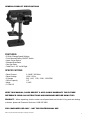
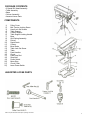
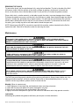
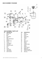
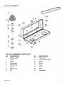
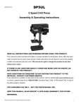
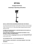
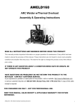
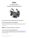
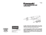
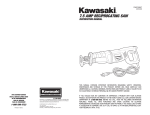
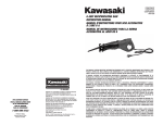
DP5UL
(DP5UL201311)
5 Speed Drill Press
Assembly & Operating Instructions
READ ALL INSTRUCTIONS AND WARNINGS BEFORE USING THIS PRODUCT.
This manual provides important information on proper operation & maintenance. Every effort has been
made to ensure the accuracy of this manual. These instructions are not meant to cover every possible
condition and situation that may occur. We reserve the right to change this product at any time
without prior notice.
CALIFORNIA PROPOSITION 65
WARNING: You can create dust when you cut, sand, drill or grind materials such as wood, paint,
metal, concrete, cement, or other masonry. This dust often contains chemicals known to cause cancer,
birth defects, or other reproductive harm. Wear protective gear.
WARNING: This product or its power cord may contain chemicals, including lead, known to the State of
California to cause cancer and birth defects or other reproductive harm. Wash hands after handling.
IF THERE IS ANY QUESTION ABOUT A CONDITION BEING SAFE OR UNSAFE, DO
NOT OPERATE THIS PRODUCT!
HAVE QUESTIONS OR PROBLEMS? DO NOT RETURN THIS PRODUCT TO THE
RETAILER - CONTACT CUSTOMER SERVICE.
If you experience a problem or need parts for this product, visit our website http://www.buffalotools.com
or call our customer help line at 1-888-287-6981, Monday-Friday, 8 AM - 4 PM Central Time. A copy of
the sales receipt is required.
FOR CONSUMER USE ONLY – NOT FOR PROFESSIONAL USE.
KEEP THIS MANUAL, SALES RECEIPT & APPLICABLE WARRANTY FOR FUTURE
REFERENCE.
DP5UL 5 Speed Drill Press Assembly & Operating Instructions
1
TABLE OF CONTENTS
RECOGNIZE SAFETY SYMBOLS, WORDS AND LABELS ........................................................................ 2
SERVICE..................................................................................................................................................... 6
SPECIFIC SAFETY RULES AND/OR SYMBOLS........................................................................................ 6
PACKAGE CONTENTS............................................................................................................................... 7
COMPONENTS ........................................................................................................................................... 7
ASSEMBLY ................................................................................................................................................. 9
OPERATION ............................................................................................................................................. 11
MAINTENANCE ........................................................................................................................................ 12
ACCESSORIES......................................................................................................................................... 13
TROUBLESHOOTING............................................................................................................................... 13
PARTS DIAGRAM ..................................................................................................................................... 14
PARTS LIST .............................................................................................................................................. 14
RECOGNIZE SAFETY SYMBOLS, WORDS AND LABELS
What You Need to Know About Safety Instructions
Warning and Important Safety Instructions appearing in this manual are not meant to cover all possible
conditions and situations that may occur. Common sense, caution and care must be exercised when
assembling or using this product.
Always contact your dealer, distributor, service agent or manufacturer about problems or conditions you
do not understand.
THIS IS A SAFETY ALERT SYMBOL. IT IS USED TO ALERT YOU TO
POTENTIAL PERSONAL INJURY HAZARDS. OBEY ALL SAFETY MESSAGES
THAT FOLLOW THIS SYMBOL TO AVOID POSSIBLE INJURY OR DEATH.
THIS IS A SAFETY ALERT SYMBOL. IT IS USED TO ALERT YOU TO
POTENTIAL PERSONAL INJURY HAZARDS. OBEY ALL SAFETY MESSAGES
THAT FOLLOW THIS SYMBOL TO AVOID POSSIBLE INJURY OR DEATH.
DP5UL 5 Speed Drill Press Assembly & Operating Instructions
2
GENERAL PRODUCT SPECIFICATIONS
FEATURES:
• 5 Quick-Change Speed Settings
• Front Mounted Safety ON/OFF Switch
• Laser Center Device
• Stamped Steel Base
• Cast Iron Body
• TableTilts 0 - 45° Left & Right
SPECIFICATIONS
• Rated Current
• Rated Voltage
• 5 Speeds
• Chuck Capacity
• Motor
• C CSA US
2.3 AMP / 250 Watt
120V / 60 Hz
620, 1100, 1720, 2340, 3100 RPM
1/2"
1/4 HP
KEEP THIS MANUAL, SALES RECEIPT & APPLICABLE WARRANTY FOR FUTURE
REFERENCE. READ ALL INSTRUCTIONS AND WARNINGS BEFORE USING THIS
PRODUCT. When unpacking, check to make sure all parts listed are included. If any parts are missing
or broken, please call Customer Service at 1-888-287-6981.
FOR CONSUMER USE ONLY – NOT FOR PROFESSIONAL USE
DP5UL 5 Speed Drill Press Assembly & Operating Instructions
3
IMPORTANT SAFETY RULES
COMMON SENSE AND CAUTION ARE FACTORS WHICH CANNOT BE BUILT INTO ANY PRODUCT.
THESE FACTORS MUST BE SUPPLIED BY THE OPERATOR.
Keep your work area clean and well lit. Cluttered work benches and dark work areas may cause accidents
or injury.
Do not operate drill in explosive areas, such as in the presence of flammable liquids, gases or dust.
The drill may create sparks which may ignite the dust or fumes.
KEEP BYSTANDERS, CHILDREN & VISITORS AWAY WHILE OPERATING THE DRILL.
DISTRACTIONS CAN CAUSE YOU TO LOSE CONTROL.
Double insulated tools are equipped with a polarized plug (one blade is wider than the other.) This plug
will fit in a polarized outlet only one way. If the plug does not fit fully in the outlet, reverse the plug. If it
still does not fit, contact a qualified electrician to install a polarized outlet. Do not change the plug in
any way. Double insulation eliminates the need for the three wire
grounded power cord and grounded power supply system.
Avoid body contact with grounded surfaces such as pipes, radiators, ranges and refrigerators. There is
an increased risk of electric shock if your body is grounded.
Do not abuse the cord. Never use the cord to carry the tool or pull the plug from an outlet. Keep the
cord away from heat, oil, sharp edges, or moving parts. Replace damaged cords immediately. Damaged
cords increase the risk of electric shock.
When operating the tool outside, use an outdoor extension cord marked “WA” or “W.” These cords are
rated for outdoor use and reduce the risk of electric shock. Make sure the extension cord being used is in good
condition. If there are any cuts or nicks (no matter how deep) in the insulation, DO NOT use that cord. Also,
make sure the extension cord is heavy enough to carry the current needed. DO NOT use small "around-thehouse” lamp extension cords. These cords can easily overheat and/or catch fire when used with power tools.
Do not force tool. Use the correct tool for your application. The correct tool will do the job better and safer
at the rate for which it is designed.
Do not use the tool if the power switch does not turn it “ON” or “OFF”. Any tool that cannot be controlled
with the switch is dangerous and must be repaired.
Disconnect the power cord plug from the power source before making any adjustments, changing
accessories or storing the tool. These safety measures reduce the risk of starting the tool accidentally.
STORE IDLE TOOLS OUT OF REACH OF CHILDREN AND OTHER UNTRAINED PERSONS. TOOLS
ARE DANGEROUS IN THE HANDS OF UNTRAINED USERS.
PEOPLE WITH PACEMAKERS OR OTHER ELECTRONIC DEVICES SHOULD CONSULT WITH A
PHYSICIAN BEFORE OPERATING THIS PRODUCT. INTERRUPTION OR FAILURE OF THE
PACEMAKER COULD OCCUR WHEN ELECTRICAL EQUIPMENT IS OPERATED WITHIN CLOSE
PROXIMITY OF ELECTRICAL DEVICES.
DP5UL 5 Speed Drill Press Assembly & Operating Instructions
4
Wash hands after handling the power cord. Touching the power cord could expose you to lead, which
is known in the State of California to cause cancer, birth defects and other reproductive harm.
All work areas should be clean and well lit. Accidents are more likely to occur in poorly lit and
cluttered areas.
Keep children, and other distractions at a distance while operating power tools.
Keep the power cord in good condition, and replace damaged cords immediately. Do not use the
cord to pull the plug from the outlet. Keep the cord away from materials and surfaces that could
damage cords. The risk of electric shock increases when the power cord is damaged.
Always use the appropriate extension cord, making sure it is rated for use with drills. Always be sure
the extension cords are in good condition, free of cuts or nicks in the insulation. If using the drill in an
outside area with an extension cord, make sure the cord is rated for outdoor use.
Do not make contact with a grounded surface while using this power tool. Contact with surfaces like
pipes, radiators or major appliances increases your risk of electric shock.
Use common sense while operating this drill.
Do not use this drill if you are:
Feeling tired or are under the influence of alcohol or drugs.
Wearing loose clothing or jewelry. Keep long hair pulled back and away from moving parts.
Overreaching or have improper footing. Handling the tool in this way could cause serious injury.
When using this drill always:
Wear the proper safety equipment, such as safety goggles, dust masks, non-skid shoes, etc.
Be sure all adjusting keys or wrenches have been removed before starting the drill.
Be sure the power switch is in the “OFF” position before plugging the drill into an electrical outlet.
Safety glasses and ear protection must be worn during operation.
DP5UL 5 Speed Drill Press Assembly & Operating Instructions
5
FOLLOW THESE STEPS TO MAINTAIN SAFE WORKING CONDITIONS AND GOOD WORKING
CONDITION OF POWER TOOLS. IMPROPER CARE CAN RESULT IN ELECTRIC SHOCK OR SERIOUS
INJURY.
Secure and support the work piece using clamps. Do not use your hands to hold the piece in place.
Use the correct tool for the job. Using the correct tool is safer and faster.
Make sure the power switch is in good working order. If the power switch no longer turns the tool “ON”
or “OFF”, discontinue use, and have the tool replaced or repaired.
Remove the power cord from the power source before storage, changing accessories, or moving the
tool.
Keep out of reach of children, or any untrained person. Store tools in a safe and dry place.
Keep tools clean, and cutting tools sharp. Maintaining tools with proper care will increase the life of the
power tool, and reduce the risk of injury.
Check to be sure all moving parts are free from binding and are properly aligned.
Use only accessories that are recommended by the manufacturer for your tool model.
SERVICE
Tool service must be performed only by qualified repair personnel. Service or maintenance by
unqualified personnel could result in a risk of injury.
When servicing a tool, use only identical replacement parts and follow instructions in the manual.
Use of unauthorized parts or failure to follow maintenance Instructions may create a risk of shock or injury.
SAVE THESE INSTRUCTIONS FOR FUTURE REFERENCE.
This manual contains important information regarding safety, operation, maintenance and storage of this
product. Before use, read carefully and understand all warnings, cautions, instructions and labels. Failure to
do so could result in serious personal injury, property damage or even death.
DP5UL 5 Speed Drill Press Assembly & Operating Instructions
6
IMPORTANT SAFETY INSTRUCTIONS
BEFORE USING THIS TOOL, YOU NEED TO BECOME FAMILIAR WITH ITS OPERATION. IF YOU ARE
UNSURE ABOUT THE OPERATION OF THE TOOL, OR HAVE ANY QUESTIONS ABOUT ITS PROPER
USE, CALL THE CUSTOMER SERVICE DEPARTMENT AT 1-888-287-6981. FOLLOW THESE
INSTRUCTIONS FOR SAFE HANDLING OF THE TOOL:
Always secure and support the work piece using clamps. Do not use your hands to hold the piece in
place.
Be sure your work area is clean and secure before turning the power switch into the “ON” position. Be
sure the area is free from all foreign material, nails, staples, or any other material.
Turn the drill “OFF” and unplug from the power source before making any changes or adjustments to
the drill.
Do not use solvents containing carbon tetrachloride, ammonia or acetone to clean the drill. Never use
gasoline, paint thinner, or other caustic chemicals that can damage the plastic parts of the tool.
Always use the appropriate safety gear when operating this drill. Including but not limited, to goggles,
dust mask or respirator. Always work in a well-ventilated area to reduce your exposure to harmful
chemicals and dust particles.
Keep hands away from the cutting area.
Do not reach under the work piece.
SPECIFIC SAFETY RULES AND/OR SYMBOLS
SYMBOLS
THE FOLLOWING SYMBOLS MAY BE USED ON YOUR TOOL. BE FAMILIAR WITH AND LEARN THE
SYMBOLS TO OPERATE THE TOOL SAFELY.
SYMBOL
V
A
HZ
W
KG
NAME
VOLTS
AMPERES
HERTZ
WATT
KILOGRAMS
ALTERNATING CURRENT
DIRECT CURRENT
ALTERNATING OR DIRECT
CURRENT
EARTHING TERMINAL
DESCRIPTION
VOLTAGE (POTENTIAL)
CURRENT
FREQUENCY (CYCLES PER SECOND)
POWER
WEIGHT
TYPE OF CURRENT
TYPE OF CURRENT
TYPE OF CURRENT
CLASS II CONSTRUCTION
MINUTES
SECONDS
DIAMETER
NO LOAD SPEED
DENOTES DOUBLE INSULATION
TIME
TIME
SIZE OF DRILL BITS, GRINDING WHEELS, ETC.
NO-LOAD ROTATIONAL SPEED
…/MIN
REVOLUTIONS PER MINUTE
1,2,3…
RING SELECTOR SETTINGS
REVOLUTIONS, SURFACE SPEED, STROKES, ETC. PER
MINUTE
SPEED, TORQUE OR POSITION SETTINGS
MIN
S
DP5UL 5 Speed Drill Press Assembly & Operating Instructions
GROUNDING TERMINAL
7
PACKAGE CONTENTS
• 5 Speed Drill Head Assembly
• Table Assembly
• Base
• Column Assembly
• Assorted Loose Parts
COMPONENTS
1)
2)
3)
4)
5)
6)
7)
8)
9)
10)
11)
12)
13)
14)
15)
16)
17)
18)
19)
20)
21)
22)
Pulley Cover
Belt Tension Locking Screw
Head Lock Set Screws
Table Support
Column Support
Table Support Locking Handle
Base
Quill Spring Assembly
Pointer
Depth Scale
Column
Bevel Scale
Table Lock Set Screw
Table
Feed Handles
Chuck
Feed Stop Rod
Stop Nuts
Power Switch
Motor Stop
Chuck Collar
Laser Power Switch
ASSORTED LOOSE PARTS
DP5UL 5 Speed Drill Press Assembly & Operating Instructions
8
Assembly
Do not stare directly at the laser beam. Never aim the beam at any person or object other than the
work piece. Do not deliberately aim the beam at personnel. Staring at the beam may cause flash
blindness.
UNPACK PRODUCT FROM PACKAGE AND REVIEW CONTENTS. KEEP ALL
PACKAGING UNTIL PRODUCT HAS BEEN REVIEWED.
Do not operate the machine until it is completely assembled.
Make sure the proper electrical regulations are followed, and that the machine is properly grounded. Before
switching the machine ON, ALWAYS: a. Make sure all chuck keys, spanners and wrenches are removed
from the machine. b. Examine the setup carefully, making certain that the workpiece is perfectly secure.
c. Make sure your clothing is properly adjusted.
Make all adjustments with the power OFF.
Always use the correct drilling speeds for the drill size, and the type of material being drilled.
NEVER leave the drill unattended while it is running. Turn the machine OFF and do not leave until it has
come to a complete stop. When you have finished with the machine, always remove and store the drill bits.
CAUTION: This Drill Press is designed for use with Drill Bits and Mortising attachments ONLY.
The use of other cutting tools or accessories could be hazardous. ALWAYS use clamps, or a drill
vise bolted to the table, to hold the work. It should NEVER be held in bare hands.
USING THE LASER
The laser light/laser radiation used in this laser centering device system is Class 2 with maximum 1 mW
and 400nm - 700nm wavelengths. These lasers do not normally present an optical hazard, although staring
at the beam may cause flash blindness.
Changing the Batteries
Unclip the battery cover to gain access to the batteries. (Figure A)
Replace both AA batteries, taking care to insert the new batteries
with the correct polarity. (Figure B)
(Figure A)
(Figure B)
Use only 2 AA batteries. DO NOT mix old and new batteries. DO NOT mix alkaline, standard (carbon-zinc)
or rechargeable (nickel-cadmium) batteries.
Replace the laser light battery cover and make certain that the light is not directed towards the eye of a
person. Always make sure that the laser beam is aimed at a sturdy work piece without reflective surfaces,
i.e. wood or rough surfaces are acceptable. Bright, shiny, reflective sheet steel or the like is not suitable for
laser use, as the reflective surface could direct the beam back at the operator. Only turn the laser beam on
after the work piece is in place. CAUTION: Remove the laser light batteries when tool is to be stored
without use for a few days.
Resetting the Laser Beam
Loosen the set screw on each of the laser tubes and adjust the tubes until the two beams intersect at the
point where the drill bit touches the work piece. Retighten the set screws more. If left in position, the
batteries might leak and damage the laser light assembly. Damage caused by battery leakage is not
covered under warranty.
DP5UL 5 Speed Drill Press Assembly & Operating Instructions
9
Column Assembly to Base
NOTE: Ideally, the base should be firmly bolted to the floor, prior to assembly of other components. The
mounting surface must be flat, level and capable of supporting the drill weight.
With the base on a flat level surface, bolt on the Column using the 4.M10 Hex head screws provided and
tighten. Carefully locate the table in its support and tighten up with the table locking handle. Check to
make sure the column securing set screws, at the column support, are tight. Fit the crank to the shaft on
the crank assembly.
Head to Column
NOTE: It may be necessary to unscrew the Head Lock Set Screws slightly to make sure they do not
protrude internally as this would prevent the head from sliding fully into position. 1. Raise the head and
locate it on top of the column. 2. Align the head with the base and firmly secure with the set screws using
the wrench. Locate the three feed handles and screw them into the hub of the spindle feed shaft.
Pulley Cover Knob
Locate the knob, with pan head screw and attach to the cover, screwing on tightly.
Installing the Chuck
1. Slide the table up the column and secure it to within 6" of the spindle.
2. Open the jaws of the chuck to their maximum, using the chuck key supplied.
3. Put a piece of scrap wood on to the table to protect the chuck nose.
4. Make sure all parts are thoroughly clean, dry, and burr free.
5. Place the chuck over the end of the arbor and pull the spindle down using the feed handles.
Fitting the Drive Belts
Undo the Belt Tension Locking Screws (one on either side of the head) and turn the Belt Tension Lever
clockwise to bring the Motor Pulley closer to the Spindle Pulley (which will allow the belts to be slipped on
with ease).
Lightly grease the idler pulley pivot shaft and locate the idler pulley assembly in its' mounting between the
Motor and spindle Pulleys. Consult the chart inside the belt cover, and fit the belts in the position
corresponding to spindle/drill speed required.
Turn the Belt Tension Lever counter-clockwise so that tension is applied to the belts. Tension is correct
when the belts deflect by approx. 1/2" at their centers of run when using reasonable thumb pressure. Lock
the motor in the position with the Belt Tension Locking Screws. 1. The idler pulley will 'float' so that
tension is applied equally to both belts. 2. If the belt should slip while drilling, adjust the belt tension.
DP5UL 5 Speed Drill Press Assembly & Operating Instructions
10
SETTINGS AND ADJUSTMENTS
Table
The table may be raised, lowered or swivelled about the column, by loosening the table support locking
handle. Adjust accordingly using the table crank, and re-tighten the locking handle. If the table assembly
moves stiffly when being swivelled about the column, loosen the upper collar allen screw (at the rack) to
allow the collar to move very slightly, thereby providing a little more clearance between rack and collar.
Tighten the allen screw when satisfied. The table may also be turned on its axis by loosening the pinch
bolt at its' mounting shaft.
Spindle Depth
Located around the spindle feed shaft is a Depth Stop Collar, printed with a graduated scale. The collar is
capable of turning about the shaft and may be locked in place by the locking screw. The scale is printed in
both inches and metric. To set a drilling depth: 1. With the power OFF, lower the drill bit so that it contacts
the work, and hold in that position. 2. Loosen the locking screw and turn the collar so that the
measurement for the depth of hole required is in line with the pointer (C). Lock the collar in this position
using the locking screw. The drill is now set to drill holes to your predetermined depth, from that particular
start point.
Changing Drill Speed
Before changing the speed, make sure the machine is switched OFF, and unplugged. Undo the Belt
Tension Locking Screws on either side of the head and turn lever clockwise to relieve any tension on the
belts. Refer to the chart inside the belt cover install the belts in the positions corresponding to the spindle
speed required. Level the motor, on its bracket, away from the head, by turning lever counter clockwise so
that tension is applied to the belts.
NOTE: The idler pulley will 'float' so that tension is equally applied to both belts. Tension is correct when
the belts deflect by approx. 1/2" at their center when using reasonable thumb pressure. Lock the motor in
this position using the two locking screws. If the belt should slip while drilling, adjust the belt tension.
OPERATION
WEAR SAFETY EYEWEAR AND DUST FILTERS OR RESPIRATORS WHILE USING THIS TOOL.
lnsert the drill bit into the jaws of the chuck by approximately 1". Be certain that the jaws do not touch the
flutes of the drill. Before tightening the chuck, make sure that the drill bit is centered within the jaws. Make
sure the table height and position is set so that drill travel is sufficient for the job in hand.
Make sure the work is securely clamped, or held in a drill vise bolted to the table. Never hold it with bare
hands. Severe personal injury may be caused if the workpiece is forced out of the operator's hand, and
damage to the machine incurred if the work strikes the column. If the piece is of irregular shape and
cannot be laid flat on the table, it should be securely blocked and clamped. Any tilting, twisting or shifting,
results not only in a rough hole, but also increases drill bit breakage.
For small workpieces that cannot be clamped to the table, use a Drill Press Vise. The vise must be
clamped or bolted to the table. When drilling completely through wood, always position a piece of scrap
wood between the workpiece and the table to prevent splintering on the underside of the workpiece as the
drill breaks through. The scrap piece of wood must make contact with the left side of the column. In
addition, set the depth of drill travel so that the drill cannot possibly come into contact with the table, or,
align the table so that the center hole is directly in line with the drill bit. When completely satisfied that the
setup is sound, lower the Chuck Guard into place, and switch the machine ON.
DP5UL 5 Speed Drill Press Assembly & Operating Instructions
11
REMOVING THE CHUCK
To remove the chuck, pull the spindle down fully, using the feed handles. The slot in the side of the Quill
will become visible. Note the position of the chuck, perhaps by placing a chalk mark, in line with the
chuck, on the column, then raise the table so that it is only an inch or so below the position marked.
Place a thick cloth, or similar material, on the table to catch the chuck, to prevent damage when it drops.
Pull down the spindle once more, until the slot in the Quill tube is visible. lnsert the drift wedge into the slot
and give it a sharp tap, preferably with a copper hammer. This will break the seal between the quill tube
and the arbor, allowing the chuck to fall free, on to the cloth on the table. To disconnect the chuck from
the arbor, give it a sharp rap with a soft head mallet to break the taper seal.
NOTE: Morse taper drills (MTS), may also be used with this machine, and are inserted into the Quill to
replace the arbor. Removal is the same as that for removing the chuck.
Maintenance
DISCONNECT THE POWER SUPPLY BEFORE CLEANING. WEAR SAFETY EYEWEAR BEFORE
CLEANING. USED COMPRESSED DRY AIR TO BLOW OFF DUST AND DEBRIS. USE A SOFT BRISTLE
BRUSH IF COMPRESSED AIR IS NOT AVAILABLE.
APPLYING EXCESSIVE FORCE TO THE TOOL CAN OVERLOAD THE MOTOR, DECREASE THE LIFE
AND INCREASE THE WEAR ON THE TOOL.
SOME CHEMICALS CAN DAMAGE THE PRODUCT. DO NOT USE HARSH CHEMICALS SUCH AS
GASOLINE, CARBON TETRACHLORIDE, PAINT THINNER, ETC.
A QUALIFIED REPAIR TECHNICIAN MUST PERFORM ANY TOOL SERVICE OR REPAIR. SERVICE OR
MAINTENANCE PERFORMED BY UNQUALIFIED PERSONNEL COULD RESULT IN INJURY. USE ONLY
IDENTICAL REPLACEMENT PARTS. USE OF UNAUTHORIZED PARTS OR FAILURE TO FOLLOW
MAINTENANCE INSTRUCTIONS MAY CREATE A RISK OF ELECTRIC SHOCK OR INJURY.
DO NOT MAKE CONTACT WITH A GROUNDED SURFACE WHILE USING DRILL PRESS. CONTACT
WITH SURFACES LIKE PIPES, RADIATORS OR MAJOR APPLIANCES INCREASE YOUR RISK OF
ELECTRIC SHOCK.
The Drill Press must be properly maintained for maximum performance. Always inspect before use. Any
damage should be repaired, and faults rectified. Please refer to the troubleshooting chart. If you are
unable to correct any problems, please contact customer service.
Monthly (When in constant use)
1. Check tightness of mounting bolts, and head and column securing set screws.
2. Check belt for wear and replace if frayed or damaged in any way.
3. Blow out any dust that may have accumulated in the motor fan.
4. Apply a thin coat of wax paste or light oil to the column for lubrication and to help prevent corrosion.
Lubrication
All bearings are packed with grease at the factory and require no further lubrication.
DP5UL 5 Speed Drill Press Assembly & Operating Instructions
12
ACCESSORIES
USE ONLY ACCESSORIES THAT ARE RECOMMENDED BY THE MANUFACTURER FOR YOUR MODEL.
ACCESSORIES THAT MAY BE SUITABLE FOR ONE TOOL MAY BECOME HAZARDOUS WHEN USED ON
ANOTHER TOOL.
ALWAYS ATTACH GROUNDED (3-PRONG) EXTENSION CORDS TO GROUNDED
(3-PRONG) OUTLETS.
IF YOU MUST USE AN EXTENSION CORD, BE SURE THAT THE GAUGE IS LARGE ENOUGH TO CARRY
THE AMOUNT OF CURRENT NECESSARY FOR YOUR POWER TOOL. IF NOT, YOUR TOOL MAY
EXPERIENCE A LOSS OF POWER, EXCESSIVE VOLTAGE DROP OR OVERHEATING. FOR EXAMPLE,
THE SMALLER THE GAUGE NUMBER, THE HEAVIER THE CORD.
TROUBLESHOOTING
Noisy? Review the probable cause and remedy:
A) Incorrect belt tension
B) Dry spindle
C) Loose pulley lubricate
D) Worn bearing
A) Adjust tension operation
B) Remove spindle / quill assembly and lubricate
C) Tighten Pulley
D) Replace bearing
Excessive drill wobble? Review the probable cause and remedy:
A) Loose chuck
A) Tighten by pressing chuck down on to
a block of wood against the table.
B) Worn spindle or bearing
B) Replace spindle shaft or bearing
C) Worn chuck
C) Replace chuck
D) Bent drill bit
D) Replace drill bit
Motor won't start? Review the probable cause and remedy:
A) Power supply
A) Check power cord/fuse start
B) Motor connection
B) Check motor connections
C) NVR switch connections
C) Check switch connections
D) Faulty Switch
D) Replace switch
E) Motor Windings Burned
E) Replace Motor
Drill Bit Binds in Workpiece? Review the probable cause and remedy:
A) Excessive Feed Pressure
A) Apply less pressure
B) Loose Belt
B) Check Belt tension
C) Loose Drill Bit
C) Tighten drill bit with key
D) Incorrect drill speed
D) Refer to Cutting Speed chart, and
adjust drill speed accordingly
Table difficult to raise? Review the probable cause and remedy:
A) Needs lubrication
A) Lubricate with light oil
B) Table lock tightened
B) Loosen clamp
DP5UL 5 Speed Drill Press Assembly & Operating Instructions
13
HEAD ASSEMBLY DIAGRAM
DP5UL 5 Speed Drill Press Assembly & Operating Instructions
14
QUILL / BASE & TABLE ASSEMBLY DIAGRAM
DP5UL 5 Speed Drill Press Assembly & Operating Instructions
15
PULLEY ASSEMBLY
(DP5UL201311)
DP5UL 5 Speed Drill Press Assembly & Operating Instructions
16