1
Technical Manual
For machines beginning with Serial no. U-1352
Undercounter
Dishwasher
Champion
Model
Temperature with Built-in Booster
UH-200B High
Fresh Water Final Rinse
UH-200
High Temperature
Fresh Water Final Rinse
Temperature with Built-in Booster
UH-100B High
Pumped Fresh Water Final Rinse
UH-100
High Temperature
Pumped Fresh Water Final Rinse
UL-100
Low Temperature
Chemical Sanitizing Rinse
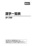
Model UH-200B Shown
Machine Serial No.
June, 2001
Champion Manual P/N
P. O. Box 4149
Winston-Salem, North Carolina 27115-4149
336/661-1556
Fax: 336/661-1660
112653
REV. C
2674 N. Service Road
Jordan Station, Ontario, Canada L0R 1S0
905/562-4195
Fax: 905/562-4618
Champion Industries, Inc.
Complete the information below for quick reference.
Model Number
Serial Number
Voltage and Phase
Champion Parts Supplier
Phone
Champion Service Agency
Phone
Champion (USA)
National Service Department
Champion (Canada)
National Service Department
Phone:
Phone:
Fax:
1(336) 661-1556
1(800) 858-4477
1(336) 661-1660
Fax:
1(905) 562-4195
1(800) 263-5798
1(905) 562-4618
Note: When calling to order parts, be sure to have the model number, serial number,
voltage and phase of your machine.
Champion
Machine Data Plate with
model & serial number
Machine
located on the front of the
lower panel.
COPYRIGHT © 2001 by Champion Industries, Inc. All Rights Reserved.
REVISION RECORD
REVISION RECORD
Revision
Date
Revised
Pages
Serial Number
Effectivity
Comments
2/25/99
All
U-1352
First issue of manual and
replacement parts lists
10/25/99
7, 9, 10,
92, 93
ALL
Increased size of supply
line, line strainer, and PRV
from 1/2" to 3/4" I.D.
10/25/99
75, 99
ALL
Corrected Thermistor
Resistance Chart
5/1/00
133
U-1991
Changed Models UH-200 &
UH-200B fill hose, valve to 3/4"
revised fill piping & bracket
5/1/01
142, 143
ALL
Changed P/N 112621 to
900827 prior to S/N U1938, and
113292 after S/N U1938. Changed
P/N’s 112622 & 112623 to
900828 prior to S/N U1938 and
113293 after S/N U1938.
i
REVISION RECORD
ii
SAFETY SUMMARY
SAFETY SUMMARY
Safety Symbols
•
The following symbols appear throughout this manual alerting you to potential
hazards. Statements associated with each symbol are printed in italics.
WARNING:
Warning statements indicate any condition or practice that
could result in personal injury or possible loss of life.
!
CAUTION:
Caution statements indicate any condition or practice which,
if not strictly observed or remedied, could result in damage to
or destruction of the dishwasher.
NOTE:
Note statements indicate any condition or practice which,
if observed, will help in the safe completion of a task.
General Safety Rules
•
The following general safety rules must be observed in addition to the specific cautions and
warnings presented in this manual.
•
Your Champion dishwasher uses hot water to clean and sanitize a variety of wares.
(Model UL-100 uses chemicals to sanitize wares.)
Machine surfaces and wares become hot during and immediately following normal operations.
Operators should use caution when loading and unloading wares from the machine.
•
Operators must NOT bypass a safety interlock or control to operate the dishwasher.
•
The service and maintenance instructions contained in this manual are intended for qualified
service personnel. These instructions assume that you are trained in basic electricity and
mechanical theory. If you are not a trained technician, then do not attempt to adjust or repair the
dishwasher as serious personal injury or damage to the dishwasher may result.
iii
LIMITED WARRANTY
LIMITED WARRANTY
Champion Industries Inc. (herein referred to as Champion), P.O. Box 4149, Winston-Salem, North Carolina 27115,
and P.O. Box 301, 2674 N. Service Road, Jordan Station, Canada, L0R 1S0, warrants machines, and parts, as set out
below.
Warranty of Machines: Champion warrants all new machines of its manufacture bearing the name
"Champion" and installed within the United States and Canada to be free from defects in material and workmanship for a period of one (1) year after the date of installation or fifteen (15) months after the date of shipment by
Champion, whichever occurs first. [See below for special provisions relating to glasswashers.] The warranty
registration card must be returned to Champion within ten (10) days after installation. If warranty card is not
returned to Champion within such period, the warranty will expire after one year from the date of shipment.
Champion will not assume any responsibility for extra costs for installation in any area where there are
jurisdictional problems with local trades or unions.
If a defect in workmanship or material is found to exist within the warranty period, Champion, at its election,
will either repair or replace the defective machine or accept return of the machine for full credit; provided, however, as to glasswashers, Champion's obligation with respect to labor associated with any repairs shall end
(a) 120 days after shipment, or (b) 90 days after installation, whichever occurs first. In the event that Champion
elects to repair, the labor and work to be performed in connection with the warranty shall be done during regular
working hours by a Champion authorized service technician. Defective parts become the property of Champion.
Use of replacement parts not authorized by Champion will relieve Champion of all further liability in connection
with its warranty. In no event will Champion's warranty obligation exceed Champion's charge for the machine.
The following are not covered by Champion's warranty:
a.
b.
c.
d.
e.
f.
g.
h.
i.
Lighting of gas pilots or burners.
Cleaning of gas lines.
Replacement of fuses or resetting of overload breakers.
Adjustment of thermostats.
Adjustment of clutches.
Opening or closing of utility supply valves or switching of electrical supply current.
Cleaning of valves, strainers, screens, nozzles, or spray pipes.
Performance of regular maintenance and cleaning as outlined in operator’s guide.
Damages resulting from water conditions, accidents, alterations, improper use, abuse,
tampering, improper installation, or failure to follow maintenance and operation procedures.
j. Wear on Pulper cutter blocks, pulse vanes, and auger brush.
Examples of the defects not covered by warranty include, but are not limited to: (1) Damage to the exterior or
interior finish as a result of the above, (2) Use with utility service other than that designated on the rating plate,
(3) Improper connection to utility service, (4) Inadequate or excessive water pressure, (5) Corrosion from
chemicals dispensed in excess of recommended concentrations, (6) Failure of electrical components due to
connection of chemical dispensing equipment installed by others, (7) Leaks or damage resulting from such
leaks caused by the installer, including those at machine table connections or by connection of chemical
dispensing equipment installed by others, (8) Failure to comply with local building codes, (9) Damage caused by
labor dispute.
Warranty of Parts: Champion warrants all new machine parts produced or authorized by Champion to be free
from defects in material and workmanship for a period of 90 days from date of invoice. If any defect in
material and workmanship is found to exist within the warranty period Champion will replace the defective
part without charge.
DISCLAIMER OF WARRANTIES AND LIMITATIONS OF LIABILITY. CHAMPION'S WARRANTY
IS ONLY TO THE EXTENT REFLECTED ABOVE. CHAMPION MAKES NO OTHER WARRANTIES,
EXPRESS OR IMPLIED, INCLUDING, BUT NOT LIMITED TO, ANY WARRANTY OF
MERCHANTABILITY, OR FITNESS OF PURPOSE. CHAMPION SHALL NOT BE LIABLE FOR
INCIDENTAL OR CONSEQUENTIAL DAMAGES. THE REMEDIES SET OUT ABOVE ARE
THE EXCLUSIVE REMEDIES FOR ANY DEFECTS FOUND TO EXIST IN CHAMPION DISHWASHING
MACHINES AND CHAMPION PARTS, AND ALL OTHER REMEDIES ARE EXCLUDED,
INCLUDING ANY LIABILITY FOR INCIDENTALS OR CONSEQUENTIAL DAMAGES.
Champion does not authorize any other person, including persons who deal in Champion dishwashing machines,
to change this warranty or create any other obligation in connection with Champion Dishwashing Machines.
iv
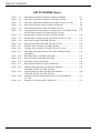
TABLE OF CONTENTS
TABLE OF CONTENTS
PAGE
Revision Record ...........................................................................................................
Safety Summary ...........................................................................................................
Limited Warranty .........................................................................................................
i
iii
iv
PART 1: GENERAL SPECIFICATIONS........................................................
1
1.1
1.2
1.3
1.4
About this Manual................................................................................................
Model Numbers ...................................................................................................
Standard Equipment and Options ........................................................................
Dimensions, Capacities, and Rough-in ................................................................
1
2
3
4
PART 2: INSTALLATION ..............................................................................
7
2.1
2.2
2.3
2.4
2.5
2.6
2.7
2.8
2.9
2.10
2.11
Introduction ..........................................................................................................
Unpack the Dishwasher .......................................................................................
Permanent Placement ...........................................................................................
Water Connections ..............................................................................................
2.4.1 Model UH-200B, UH-200 .........................................................................
2.4.2 Model UH-100B, UH-100, UL-100...........................................................
Drain Connections (All models) ..........................................................................
Installation and Service Switch (Model UH-200B, UH-100B Only) ..................
Electrical Connections (Single Phase) .................................................................
2.7.1 Model UH-200B, UH-100B.......................................................................
2.7.2 Model UH-200, UH-100, UL-100 .............................................................
Electrical Connections (Three Phase) ..................................................................
2.8.1 Model UH-200B, UH-100B.......................................................................
Chemical Connections .........................................................................................
2.9.1 General (All Models) .................................................................................
2.9.2 Models UH-200B, UH-200 (Chemical Adjust and Prime) ........................
2.9.3 Models UH-100B, UH-100 (Chemical Adjust and Prime) ........................
2.9.4 Model UL-100 (Chemical Adjust and Prime) ............................................
Installing Optional Chemical Pumps ...................................................................
2.10.1 Model UH-200B, UH-200 .......................................................................
2.10.2 Model UH-100B, UH-100 .......................................................................
Initial Start-up (All Models) ................................................................................
2.11.1 Model UH-200B, UH-200 .......................................................................
2.11.2 Model UH-100B, UH-100, UL-100.........................................................
7
7
8
8
9
10
11
12
13
13
14
15
15
16
16
19
20
21
22
22
25
26
27
28
v
TABLE OF CONTENTS
PART 3: DAILY OPERATION ........................................................................
3.1
3.2
3.3
3.4
3.5
Introduction ..........................................................................................................
Preparing your Dishwasher (All Models) ............................................................
Loading your Dishwasher (All Models) ..............................................................
Description of Operator Controls and Displays (All Models) .............................
Basic Operation ....................................................................................................
3.5.1 Model UH-200B, UH-200 .........................................................................
3.5.2 Model UH-100B, UH-100, UL-100...........................................................
29
29
30
31
34
34
36
PART 4: CLEANING and MAINTENANCE ..................................................
39
4.1
4.2
4.3
Introduction ..........................................................................................................
Daily Cleaning Schedules (All Models) ..............................................................
Deliming Schedules (All Models) .......................................................................
4.3.1 Deliming Procedure (All Models) .............................................................
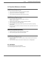
Preventive Maintenance Schedules (All Models) ................................................
Lubrication (All Models) .....................................................................................
39
39
40
40
41
41
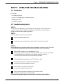
PART 5: OPERATOR TROUBLESHOOTING ...............................................
43
4.4
4.5
5.1
5.2
5.3
5.4
5.5
Introduction ..........................................................................................................
Troubleshooting Basics ........................................................................................
Using the Touchpad/Display to Evaluate Problems .............................................
Reading Error Codes ............................................................................................
Troubleshooting Guide ........................................................................................
43
43
44
45
46
PART 6: SERVICE TROUBLESHOOTING ...................................................
51
6.1
6.2
6.3
6.4
vi
29
Introduction ..........................................................................................................
Operation Sequence and Timing Charts ..............................................................
6.2.1 Model UH-200B, UH-200 .........................................................................
6.2.2 Model UH-100B, UH-100 .........................................................................
6.2.3 Model UL-100 ...........................................................................................
Error Codes ..........................................................................................................
Troubleshooting Guide ........................................................................................
51
52
52
54
56
58
60
TABLE OF CONTENTS
PART 7: SOLID STATE CIRCUIT BOARDS .................................................
7.1
7.2
7.3
61
Introduction .....................................................................................................
Control Cabinet Layout and Board Function ..................................................
Replacement Circuit Board Set-up ..................................................................
7.3.1 Timer Control Board Program Jumper Settings ....................................
7.3.2 Timer Control Board LED Status Lights ...............................................
7.3.3 Temperature/Pressure Control Board Program Jumper Settings ...........
7.3.4 Temperature/Pressure Control Board LED Status Lights .....................
7.3.5 Time Select (Fill/Chemical Dispenser) Board .......................................
Circuit Board Connector Diagrams and Test Points ........................................
7.4.1 Timer Control and Time Select (Fill/Chemical Dispenser) Board .......
7.4.2 Temperature/Pressure Display Board ...................................................
7.4.3 Touchpad/Display .................................................................................
Circuit Board Removal and Replacement .......................................................
7.5.1 Timer Control Board Removal ..............................................................
7.5.2 Temperature/Pressure Display Board Removal .....................................
7.5.3 Touchpad/Display Removal and Replacement ......................................
7.5.4 Time Select (Fill/Chemical Dispenser) Board Removal .......................
61
61
62
62
63
64
65
66
70
72
74
76
78
78
80
82
85
PART 8: COMPONENT REPAIR AND REPLACEMENT .............................
87
7.4
7.5
8.1
8.2
Introduction ..........................................................................................................
8.1.1 Special Tools and Materials ................................................................
8.1.2 Electrical Component Locator Diagram .............................................
8.1.3 Troubleshooting the 10-point Terminal Board ...................................
Components .........................................................................................................
8.2.1 Pressure Reducing Valve, (PRV), Adjustment ....................................
Model UH-200B, UH-200
8.2.2 Water Line Strainer .............................................................................
Model UH-200B, UH-200
Model UH-100B, UH-100, UL-100
8.2.3 Fill/Rinse Water Solenoid Valve .........................................................
Model UH-200B, UH-200
Model UH-100B, UH-100, UL-100
8.2.4 Water Level Probe ..............................................................................
Model UH-200B, UH-200
8.2.5 Vacuum Breaker .................................................................................
Model UH-200B, UH-200
8.2.6 Pressure Transducer ............................................................................
Model UH-200B, UH-200
8.2.7 Thermistors (All Models) ...................................................................
8.2.8 Wash Tank Heater and High Limit Thermostat ..................................
(All models except UL-100)
8.2.9 Booster Tank Heater and High Limit Thermostat ..............................
Model UH-200B, UH-100B
87
87
88
90
92
92
93
93
95
96
97
99
100
101
vii
TABLE OF CONTENTS
PART 8: ..........................................................................................................
COMPONENT REPAIR AND REPLACEMENT (CONT.)
8.2
8.2.10
8.2.11
8.2.12
8.2.13
8.2.14
8.2.15
8.2.16
102
104
105
106
107
108
109
PART 9:
REPLACEMENT PARTS ..........................................................
111
PART 10:
ELECTRICAL SCHEMATICS ...................................................
155
A701543
A701542
A701545
A701544
A701546
A701628
A701627
viii
Components (Cont.)
Wash Pump/Motor (All Models) ........................................................................
Drain Pump/Motor, Drain Valve (All Models) ..................................................
Wash Arm Bearings (All Models) ......................................................................
Rinse Arm Bearings ............................................................................................
Model UH-200B, UH-200
Door Shock and Hinge Assembly (All Models) .................................................
Door Safety Switch and Magnet (All Models) ...................................................
Circuit Breaker (All Models)..............................................................................
UH-200B
UH-200
UH-100B
UH-100
UL-100
UH-200B
UH-100B
Single Phase
Single Phase
Single Phase
Single Phase
Single Phase
Three Phase
Three Phase
TABLE OF CONTENTS
LIST OF FIGURES
Figure
Figure
Figure
Figure
Figure
Figure
Figure
Figure
Figure
Figure
Figure
Figure
Figure
Figure
Figure
Figure
Figure
Figure
Figure
Figure
Figure
Figure
Figure
Figure
Figure
2.4.1
2.4.2
2.5.3
2.6.1
2.9.1
2.9.2
2.9.3
2.9.4
2.9.5
2.9.6
2.9.7
2.9.8
2.9.9
2.10.1
2.10.2
2.10.3
3.4.1
3.4.2
5.3.1
5.3.2
6.2.1
6.2.2
6.2.3
7.2.1
7.3.1
–
–
–
–
–
–
–
–
–
–
–
–
–
–
–
–
–
–
–
–
–
–
–
–
–
Figure
7.3.2 –
Figure
7.3.3 –
Figure
Figure
7.3.4 –
7.4.1 –
Figure
7.4.2 –
Figure
Figure
Figure
7.4.3 –
8.1.1 –
8.1.2 –
Water Connections ( UH-200B, UH-200) ..............................................
Water Connections (UH-100B, UH-100, UL-100) .................................
Recommended Direct Drain Connections for All Models ......................
Installation and Service Switch (UH-200B, UH-100B Only) ................
Control Cabinet Retaining Screws ..........................................................
Fill/Chemical Dispenser Circuit Board...................................................
Chemical Bottle Placement .....................................................................
UH-200B, UH-200 Touchpad/Display ...................................................
Rinse Aid Injection Point (UH-200B, UH-200) .....................................
UH-100B, UH-100 Touchpad/Display ...................................................
Fill Chute (UH-100B, UH-100, UL-100) ...............................................
UL-100 Touchpad/Display ......................................................................
Fill Chute Discharge (UH-100B, UH-100, UL-100) ..............................
UH-200B, UH-200 Chemical Pumps ....................................................
Chemical Pump Connection Terminal Block .........................................
UH-100B, UH-100 Chemical Pumps .....................................................
Door Safety Magnet Location.................................................................
Circuit Breaker Location ........................................................................
Self-Diagnostics Display ........................................................................
LO Temperature Displayed .....................................................................
Timing Chart (UH-200B, UH-200) ........................................................
Timing Chart (UH-100B, UH-100) ........................................................
Timing Chart (UL-100) ...........................................................................
Circuit Board Layout (All Models) ........................................................
Timer Control Board Jumpers and ..........................................................
LED Status Lights
Temperature/Pressure Display Board Jumpers .......................................
and LED Status Lights
Time Select (Fill/Chemical Dispenser) ...................................................
Board Potentiometers
Rinse Aid and Sanitizer Pump Adjustment .............................................
Timer Control Board and Time Select Board .........................................
Connector Diagrams
Temperature/Display Board ....................................................................
Connector Diagrams
Touchpad/Display Connector Diagram...................................................
Electrical Component Locator Diagram .................................................
10-Point Terminal Board.........................................................................
9
9
11
12
17
18
18
19
19
20
20
21
21
22
22
25
31
31
44
44
53
55
57
61
62
64
66
69
72
74
76
88
90
ix
TABLE OF CONTENTS
LIST OF FIGURES (Cont.)
Figure
Figure
Figure
Figure
Figure
Figure
9.1
9.2
9.3
9.4
9.5
9.6
–
–
–
–
–
–
Figure
Figure
Figure
Figure
Figure
Figure
Figure
9.7
9.8
9.9
9.10
9.11
9.12
9.13
–
–
–
–
–
–
–
Figure
Figure
Figure
Figure
Figure
9.14
9.15
9.16
9.17
9.18
–
–
–
–
–
Figure 9.19 –
Figure 9.20 –
Figure 9.21 –
x
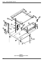
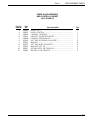
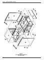
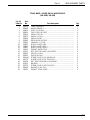
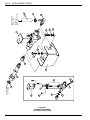
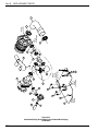
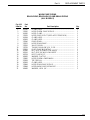
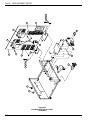
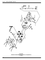
Upper Hood Assembly and Control Cabinet (All Models) .........................
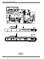
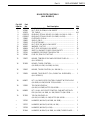
Tank, Base, Guide Rails, and Panels (UH-200B, UH-200) ........................
Tank, Base, Guide Rails, and Panels (UH-100B, UH-100, UL-100) ..........
Door and Door Safety Switch Assembly (All Models) ...............................
Final Rinse Manifold Assembly (UH-200B, UH-200) ...............................
Chemical Injection Points, Water Level Probe Assy. (UH-200B, UH-200 .
and Fill Chute Assemby (UH-100B, UH-100, UL-100)
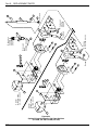
Sump and Spray Piping Assembly (UH-200B, UH-200) ............................
Sump and Spray Piping Assembly (UH-100B, UH-100, UL-100) .............
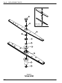
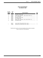
Spray Arm Assembly (UH-200B, UH-200) ................................................
Spray Arm Assembly (UH-100B, UH-100, UL-100) .................................
Fill/Rinse Valve Assembly (UH-200B, UH-200) ........................................
Fill/Rinse Valve Assembly (UH-100B, UH-100, UL-100) .........................
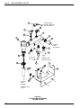
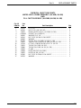
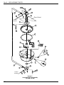
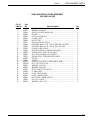
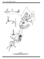
Wash Pump Piping, Drain Pump, Drain Valve and Drain Piping ...............
(All Models)
Wash Pump/Motor Assembly (All Models) ................................................
Booster Assembly (UH-200B, UH-100B) ..................................................
Solid State Controls (All Models) ...............................................................
Base Mounted Electrical Controls (All Models) .........................................
(Optional) Detergent Pump for High Temp Machines ................................
(UH-200B, UH-200, UH-100B, UH-100)
(Optional) Rinse Aid Pump for High Temp Machines ................................
(UH-200B, UH-200, UH-100B, UH-100)
(Standard) Chemical Dispensing Pumps for Low Temp Machines ............
(UL-100)
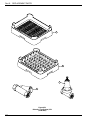
Dishracks, Line Strainer, PRV (All Models) ...............................................
112
114
116
118
120
122
124
126
128
130
132
134
136
138
140
142
144
146
148
150
152
Part 1:
GENERAL SPECIFICATIONS
PART 1: GENERAL SPECIFICATIONS
1.1 About this Manual
All information, illustrations and specifications contained in this manual are based upon the
latest product information available at the time of publication. Champion constantly improves
its products and reserves the right to make changes at any time or to change specifications or
design without notice and without incurring any obligation.
Manual Organization
This manual is divided into eleven parts:
♦ Part 1, General Specifications, introduces this manual and the dishwasher models
in general.
♦ Part 2, Installation, explains the installation of the dishwasher and describes the
connection of utilities, chemical dispensing pumps, and initial start-up.
♦ Part 3, Daily Operation, explains operator controls and basic operation.
♦ Part 4, Cleaning and Maintenance, explains cleaning, deliming, preventive maintenance,
and lubrication.
♦ Part 5, explains basic troubleshooting for the operator.
♦ Part 6, explains basic troubleshooting for the service technician.
♦ Parts 7-8, provide detailed repair procedures for the trained service technician.
♦ Part 9, contains parts diagrams and parts lists.
♦ Part 10, contains electrical schematics.
NOTE:
Unless noted otherwise, dimensions, capacities, temperatures, etc., given in this
manual are U.S. Customary Measures and the Metric Equivalents of the U.S.
customary measures.
1
Part 1:
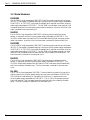
GENERAL SPECIFICATIONS
1.2 Model Numbers
UH-200B
The UH-200B is a high temperature (180°F/82°C) sanitizing machine with a built-in booster.
(40°F/22°C) rise booster is standard requiring a minimum incoming water supply temperature
of 140°F/60°C. A (70°F/39°C) rise booster is available which requires a minimum incoming
water supply temperature of 110°F/43°C. The UH-200B is a fresh water rinse machine. Final
rinse water enters the final rinse spray system under line pressure. A portion of the final rinse
water is retained for the next wash cycle.
UH-200
The UH-200 is a high temperature (180°F/82°C) sanitizing machine without a built-in
booster. It requires a minimum incoming water supply temperature of 180°F/82°C. The
UH-200 is a fresh water rinse machine. Final rinse water enters the final rinse spray system
under line pressure. A portion of the final rinse water is retained for the next wash cycle.
UH-100B
The UH-100B is a high temperature (180°F/82°C) sanitizing machine with a built-in booster.
(40°F/22°C) rise booster is standard requiring a minimum incoming water supply temperature
of 140°F/60°C. A (70°F/39°C) rise booster is available which requires a minimum incoming
water supply temperature of 110°F/43°C. The UH-100B is a fresh water pumped final rinse
machine. Final rinse water enters the wash tank and is recirculated by the wash pump. The
final rinse water is retained for the next wash cycle.
UH-100
The UH-100 is a high temperature (180°F/82°C) sanitizing machine without a built-in
booster. It requires a minimum incoming water supply temperature of 180°F/82°C. The
UH-100 is a fresh water pumped final rinse machine. Final rinse water enters the wash tank
and is recirculated by the wash pump. The final rinse water is retained for the next wash
cycle.
UL-100
The UL-100 is a low temperature (140°F/60°C) chemical sanitizing machine for use with a
sodium hypochlorite (chlorine) based sanitizer at a minimum concentration of 50 PPM (for
USA/Consult the local authority for Canada) in the final rinse. It requires a minimum
incoming water supply temperature of 140°F/60°C. The UL-100 is a fresh water pumped
final rinse machine. Final rinse water enters the wash tank and is recirculated by the wash
pump. The final rinse water is retained for the next wash cycle.
2
Part 1:
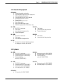
GENERAL SPECIFICATIONS
1.3 Standard Equipment
All Models
♦ 304 stainless steel construction
♦ Interchangeable upper and lower spray arms
♦ 3/4 Hp pump/motor assembly
♦ Top mounted slide-out control cabinet
♦ Solid state electronic controls
♦ Pumped drain
♦ Flexible fill and drain hoses
♦ Door safety switch
♦ Easily removable scrap screen
♦ Dishracks (peg rack and flat bottom rack)
UH-200B
♦ 40°F/22°C rise booster
♦ Tank heater
♦ Low water tank heat protection
♦ Top and side panels
UH-200
UH-100B
♦ 40°F/22°C rise booster
♦ Tank heater
♦ Low water tank heat protection
UH-100
♦ Tank heater
♦ Low water tank heat protection
♦ Top and side panels
♦ Tank heater
♦ Low water tank heat protection
UL-100
♦ Three built-in chemical dispensing pumps
for detergent, rinse aid, and sanitizer
1.3 Options
UH-200B
♦ 70°F/39°C rise booster
♦ Detergent pump kit (P/N 900799)
♦ Rinse aid pump kit (P/N 900803)
♦ Pressure reducing
valve 3/4" (P/N 107550)
UH-200
UH-100B
♦ 70°F/39°C rise booster
♦ Detergent pump kit (P/N 900800)
♦ Rinse aid pump kit (P/N 900802)
♦ Full side panel kit (P/N 900804)
UH-100
♦ Detergent pump kit (P/N 900799)
♦ Rinse aid pump kit (P/N 900803)
♦ Pressure reducing
valve 3/4" (P/N 107550)
♦ Detergent pump kit (P/N 900800)
♦ Rinse aid pump kit (P/N 900802)
All Models
♦ 6" Legs (set of 4) (P/N 324087)
3
Part 1:
GENERAL SPECIFICATIONS
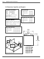
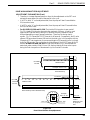
1.4 Dimensions, Capacities, and Rough-in
Dimensions (All Models)
Total Cycle Time
Height
Width
Length
UH-200B, UH-200
90 seconds
UH-100B, UH-100
120 seconds
UL-100
155 seconds
33-3/4" [858mm]
23-7/8" [607mm]
23"
[584mm]
Volume crated: 15 cu. ft. [.4 cu.m]
Approx. Shipping
weight crated: 215 lbs [98 Kg]
Wash Tank Capacities
UH-200B, UH-200 ≅ 3.6 US gal. (14 liters)
UH-100B, UH-100 ≅ 1.8 US gal. (7 liters)
Racks per hour (NSF rated)
UH-200B, UH-200
30 racks/hr.
UH-100B, UH-100
24 racks/hr.
UL-100
19 racks/hr.
UL-100 ≅ 2.3 US gal. (8.7 liters)
Water Usage (per rack)
UH-200B, UH-200
1.1 US gal. (4.2 liters)
UH-100B, UH-100
1.8 US gal. (6.8 liters)
UL-100
2.3 US gal. (8.7 liters)
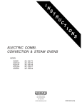
237/8"
[607]
3
2
1
23" [584]
Flexible
Conduit
Main Power
Connection
Terminal Block
Electrical Power Routing
4
2" [51]
PLAN VIEW
Model UH-200B
Model UH-200
Model UH-100B
Model UH-100
Model UL-100
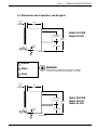
Part 1:
GENERAL SPECIFICATIONS
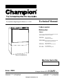
1.4 Dimensions and Capacities, and Rough-in
3" [76]
Wall
Clearance
23"
[584]
Model UH-200B
Model UH-200
143/4" [375]
Clearance
333/4"
[858]
141/4" [362]
15/8"
[42]
2 3
SIDE VIEW
1
1 Electric
WARNING:
2 Water
Refer to Part 2: Installation, Sections 2.1 through
2.9, before connecting the dishwasher to utilities.
3 Drain
3" [76]
Wall
Clearance
23"
[584]
151/2" [394]
Clearance
333/4"
[858]
Model UH-100B
Model UH-100
Model UL-100
141/4" [362]
15/8"
[42]
2 3
1
SIDE VIEW
5
Part 2:
INSTALLATION
This Page
Intentionally
Left
Blank
6
Part 2:
INSTALLATION
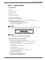
PART 2: INSTALLATION
2.1 Introduction
In This Part—
• Unpacking the dishwasher
• Permanent Placement
• Making Utility Connections
• Installing Optional Components
2.2 Unpack the Dishwasher
Your dishwasher was completely assembled, inspected, and thoroughly tested at our factory
before shipment to your installation site.
• The dishwasher is shipped on a single pallet.
• Optional components may have been shipped separately.
• Check your packing list thoroughly.
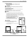
NOTE:
Immediately after unpacking your machine, inspect for any shipping damage. If damage
if found, save the packing material and contact the carrier immediately.
BE SURE TO COMPLETE AND RETURN THE
WARRANTY CARD
INCLUDED WITH YOUR MACHINE.
NOTE:
The installation of your dishwasher must meet all applicable
health and safety codes and conform to good trade practice.
Perform the following steps to unpack the dishwasher:
1. Remove protective wrap and hold downs from the pallet.
2. Inspect for any shipping damage. If damage is found, save the packing material
and contact the carrier immediately.
3. Check the interior of the dishwasher for the following items stowed inside:
• 1 set of dishracks
• Upper and lower spray arm assemblies
• Round scrap screen
• Rubber pads for leveling feet (set of 4)
• 3/4" line strainer (P/N 110768) (Model UH-200B, UH-200 Only)
• Warranty information packet
4. Remove the dishwasher from the skid.
5. Move the dishwasher to its permanent location.
Refer to Section 2.3, Permanent Placement.
7
Part 2:
INSTALLATION
2.3 Permanent Placement
Special Tools —
• Bubble level (3 ft.)
Perform the following steps to place the dishwasher in its permanent location.
Refer to the machine diagrams in Section 1.4, Dimensions and Capacities, page 4-5.
1. Before moving the dishwasher into position, inspect the location site to ensure the electrical,
plumbing, and ventilation services (if required) are provided in the correct locations.
Compare the site connections with the dishwasher to ensure they will match when the
machine is set in its permanent location.
NOTE:
Some local codes may require that the dishwasher be sealed to the floor with
silicon or comparable sealing method.
2. Lift the dishwasher and adjust the leveling feet out.
3. Position dishwasher in its permanent location.
• Minimum clearance between the rear of the machine and back wall is 3" [76mm].
• Minimum height of the machine with adjustable feet turned in fully is 33-3/4" [858mm].
4. Place a 3 ft. level on top of the dishwasher or inside the dishwasher on the track assembly
to level the dishwasher front to back. Adjust level by turning the adjustable feet. Level side
to side with the level placed on the top of the dishwasher.
5. Pull the dishwasher out far enough to gain access to the rear and prepare utility
connections. A removable rear access door is located at the back of the machine.
6. Install the rubber pads on the leveling feet prior to returning machine to its permanent
position.
2.4 Water Connections
The following warning and attention statements apply to all dishwasher models.
WARNING:
The installation of this unit must conform to local codes or, in the absence of
local codes, to all National Codes governing plumbing, sanitation, safety and
good trade practices.
!! ATTENTION INSTALLER !!
The dishwashers described in Sections 2.4.1 and 2.4.2 are fitted with 6 ft. [1829mm],
1/2" I.D. flexible fill hoses located at the rear of the machine.
Make sure supply hose does not kink, resulting in a water flow restriction.
NOTE:
Your plumbing installation must allow the machine to be pulled out for repair.
8
Part 2:
INSTALLATION
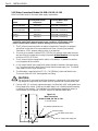
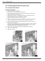
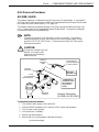
2.4.1 (Water Connections) Models UH-200B, UH-200
Refer to the Table below for minimum water supply requirements.
Minimum
Incoming Water Supply
Temperature
Minimum-Maximum
Water Supply
Flowing Pressure*
UH-200B with
40°F/22°C Booster
140°F/60°C
20-22 PSI (138-151 kPa)
UH-200B-70 with
70°F/39°C Booster
110°F/43°C
20-22 PSI (138-151 kPa)
UH-200 without
Booster
180°F/82°C
20-22 PSI (138-151 kPa)
Model
*Flowing pressure is observed when the fill water solenoid valve is open while the
machine is in a final rinse operation. Refer to Part 3, Operation, Section 3.21. for a
description of the front panel display final rinse pressure readings.
1. If flowing pressure exceeds 22 PSI/151kPa, a pressure reducing valve, PRV, must be
installed in the incoming water supply, and adjusted to the min/max listed above.
The PRV is supplied by others or may be purchased (unmounted) from Champion.
2. Champion supplies a 3/4" line strainer (unmounted) and shipped inside the dishwasher.
The line strainer must be installed in the water supply line upstream from the PRV.
3. A 3/4" manual shutoff valve (supplied by others) should be installed in the water supply
line upstream from the PRV and line strainer. The valve must be the same size as or larger
than the water supply line. The shutoff valve allows for servicing of the machine.
4. The dishwasher is supplied with a 1/2" I.D., 6 ft. [1829mm], reinforced flexible hose.
The hose is fitted with a 3/4" female garden hose fitting.
!
CAUTION:
The reinforced fill hose supplied with the dishwasher is designed for high pressure and
high temperature application and should never be replaced with common garden hose.
5. Connect a 3/4" I.D. minimum copper water supply line fitted with a 3/4" male garden hose
fitting (supplied by others). Make sure the water supply line is flushed out before making
connection to the machine.
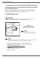
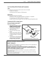
Figure 2.4.1
Water Connections
Model UH-200B, UH-200
(UH-200B shown)
6 ft. [1829mm] flexible fill hose
3/4" PRV, pressure reducing valve
3/4" line strainer
3/4" Water shutoff Valve
3/4" I.D. copper water supply line
9
Part 2:
INSTALLATION
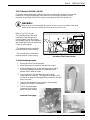
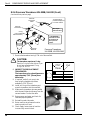
2.4.2 (Water Connections) Models UH-100B, UH-100, UL-100
Refer to the Table below for minimum water supply requirements.
Minimum
Incoming Water Supply
Temperature
Minimum-Maximum
Incoming Water Supply
Pressure*
UH-100B with
40°F/22°C Booster
140°F/60°C
25-95 PSI (173-656 kPa)
UH-100B-70 with
70°F/39°C Booster
110°F/43°C
25-95 PSI (173-656 kPa)
UH-100 without
Booster
180°F/82°C
25-95 PSI (173-656 kPa)
UL-100
140°F/60°C
25-95 PSI (173-656 kPa)
Model
*Incoming water supply pressure should be tested with a pressure gauge
(supplied by others) at the dishwasher water supply connection. Incoming water supply
pressure must be able to maintain a minimum flowing pressure of 25 PSI [173 kPa].
1. The fill solenoid valve mounted in the machine (supplied by Champion) is equipped
with a flow control that will accommodate the min./max. incoming line pressures
listed above. A PRV, pressure reducing valve, is not required.
2. If incoming line pressure is below 25 PSI [173 kPa], the customer must make the necessary provisions to increase the incoming line pressure at the dishwasher to the required
minimum of 25 PSI [173 kPa].
3. The fill solenoid valve is equipped with a built-in line strainer. A separate line strainer
is not shipped with this machine.
4. A 3/4" manual shutoff valve (supplied by others) should be installed in the water supply
line. The valve must be the same size as or larger than the water supply line. The shutoff
valve allows for servicing of the machine.
5. The dishwasher is supplied with a 1/2" I.D., 6 ft. [1829mm], reinforced flexible hose.
The hose is fitted with a 3/4" female garden hose fitting.
!
CAUTION:
The reinforced fill hose supplied with the dishwasher is designed for high pressure and
high temperature application and should never be replaced with common garden hose.
6. Connect a 3/4" I.D. minimum copper water supply line fitted with a 3/4" male garden hose
fitting (supplied by others). Make sure the water supply line is flushed out before making
connection to the machine. The installation of a pressure gauge (supplied by others) is
recommended, but not required, in the 3/4" supply line after the shutoff valve.
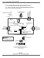
Figure 2.4.2
Water Connections
Model UH-100B, UH-100, UL-100
(UH-100B shown)
6 ft. [1829mm] flexible fill hose
Pressure Gauge
3/4" Water shutoff Valve
3/4" I.D. copper water supply line
10
Part 2:
INSTALLATION
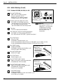
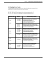
2.5 Drain Connections
The following instructions apply to all dishwasher models.
Refer to Fig. 2.5.3 below.
WARNING:
The installation of this unit must conform to local codes or, in the absence of
local codes, to all National Codes governing plumbing, sanitation, safety and
good trade practices.
!! ATTENTION INSTALLER !!
All dishwashers are fitted with 6 ft. [1829mm], 5/8" I.D. flexible reinforced drain hoses
located at the rear of the machine.
Make sure drain hose does not kink, resulting in a water flow restriction.
NOTE:
Your plumbing installation must allow the machine to be pulled out for repair.
1. The dishwasher drain hose may be routed to an indirect floor drain (not shown), or
connected directly to a sink drain (see Fig. 2.5.3). The installer must follow all local
plumbing, sanitary, and safety codes where applicable. Local codes may vary from the
recommended connections shown in Fig. 2.5.3 below.
2. Connect the 5/8" I.D. flexible reinforced drain hose supplied to a 1-1/2" wye (Y) drain
fitting. Use a 5/8" hose adapter (supplied by others).
3. Do not reduce the diameter of the drain hose connection
or add additional length to the drain hose.
Do not
4. Do not connect the drain hose to a 90° drain fitting.
use a 90°
fitting
!
CAUTION:
The drain must have a minimum flow capacity
of 15 US gal. per min [54 liters per minute], and
12.5 Imperial gallons per minute.
5. The maximum height of the drain or the drain hose should
not exceed 3 ft. [915mm].
1-1/2"
"Y"
Fitting
cut away
to show rear
cut away
to show rear
1-1/2"
"Y"
Fitting
Max. Drain
Height
3 ft.
[915mm]
1-5/8"
[42mm]
1-5/8"
[42mm]
Floor
Floor
Figure 2.5.3
Recommended Direct Drain Connections
for All Models
11
Part 2:
INSTALLATION
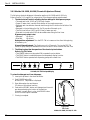
2.6 Installation and Service Switch (Model UH-200B, UH-100B Only)
The following instructions apply to Models UH-200B and UH-100B which are equipped
with a Champion built-in booster.
The Booster Installation and Service Switch is provided to fill the built-in booster tank with
water prior to placing the dishwasher in service for the first time. It can also be used by service
technicians to interrupt 120VAC control power to service the machine.
!! ATTENTION INSTALLER !!
CAUTION:
!
Failure to fill the booster before operating the dishwasher will cause damage to the
booster heater components and will void the machine warranty.
ON
LLATI
NSTA
I
R
C
E
T
IT H
BOOS RVICE SW
E
S
AND
Figure 2.6.1
Installation and Service Switch
Models UH-200B and UH-100B Only
ON
NOTE:
OFF
ILL
TER F
BOOS
Switch is located behind the lower front
panel on the left front of the dishwasher.
NOTE:
Perform the following procedure after all plumbing and electrical connections have been
made. Make sure the interior of the machine is clean and free of debris.
1. Remove screws holding lower front panel. Lift panel up, forward and off.
2. Push and hold the switch in the BOOSTER FILL position until you hear water
entering the wash tank of the machine.
DO NOT FILL THE WASH TANK WITH WATER.
3. Release the switch.
4. Push the switch up to the ON position.
5. Booster fill is complete.
12
Part 2:
INSTALLATION
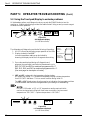
2.7 Electrical Connections (Single Phase)
2.7.1 Models UH-200B, UH-100B Only
WARNING:
The installation of electrical supplies and controls must conform to local codes or, in the
absence of local codes, the National Electrical Code and good trade practices.
WARNING:
When working on the dishwasher, disconnect the electrical service and place a red tag
at the disconnect switch to indicate work is being done on that circuit.
!! ATTENTION INSTALLER !!
Use flexible conduit to connect incoming power to the dishwasher to allow the machine to be
pulled out 5 ft. [1524mm] for servicing. A service loop is recommended. Service enters at the
right rear corner of the machine. The main connection block is located on the right side of the
dishwasher. See Section 1.4, page 4.
1. A qualified electrician must compare the electrical power supply with the machine
electrical specifications stamped on the MACHINE ELECTRICAL CONNECTION
PLATE before connecting to the incoming service through a fused disconnect switch or
circuit breaker (supplied by others). The plate is located near the main terminal block.
!
CAUTION:
DO NOT CONNECT models UH-200B or UH-100B to a 120VAC circuit
or to a 208-240VAC (2 wire system) utilizing two power wires plus a ground.
2. Models UH-200B and UH-100B utilize a 208-240VAC (3 wire plus ground system)
consisting of three power wires which includes a current carrying neutral wire.
A fourth wire for machine ground also must be provided.
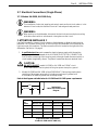
Refer to the diagram and table below for UH-200B and UH-100B power requirements.
120V
120V
208-240V
L1
L2
Voltage
Hz
Phase
G
208-240/60/1
3 Wire Plus Ground System
Diagram
N
40°F/22°C Rise Booster
70°F/39°C Rise Booster
Min. Wire Amp/
Min. Wire Amp/
Machine FLA Max. Fuse Size Machine FLA Max. Fuse Size
208/60/1
44.4
50/50
58.9
60/60
220/60/1
46.4
50/50
61.7
70/70
230/60/1
48.1
50/50
64.0
70/70
240/60/1
49.8
50/50
66.4
70/70
Single Phase Power Requirements
Models UH-200B and UH-100B Only
13
Part 2:
INSTALLATION
2.7 Electrical Connections (Single Phase) Cont.
2.7.2 Models UH-200, UH-100, UL-100 Only
WARNING:
The installation of electrical supplies and controls must conform to local codes or, in the
absence of local codes, the National Electrical Code and good trade practices.
WARNING:
When working on the dishwasher, disconnect the electrical service and place a red tag
at the disconnect switch to indicate work is being done on that circuit.
!! ATTENTION INSTALLER !!
Use flexible conduit or cable to connect incoming power to the dishwasher to allow the machine
to be pulled out 5 ft. [1524mm] for servicing. A service loop is recommended. Service enters at
the right rear corner of the machine. The main connection block is located on the right side of the
dishwasher. See Section 1.4, page 4.
1. A qualified electrician must compare the electrical power supply with the machine
electrical specifications stamped on the MACHINE ELECTRICAL CONNECTION
PLATE before connecting to the incoming service through a fused disconnect switch or
circuit breaker (supplied by others). The plate is located near the main terminal block.
2. Models UH-200, UH-100 and UL-100 utilize a 120VAC power supply.
Power cord and plug are supplied by others.
14
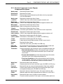
Voltage
Hz
Phase
Machine
FLA
Min. Wire
Ampacity/
Max. Fuse Size
120/60/1
23.4
25/25
Voltage
Hz
Phase
Machine
FLA
Min. Wire
Ampacity/
Max. Fuse Size
120/60/1
19.3
25/25
Voltage
Hz
Phase
Machine
FLA
Min. Wire
Ampacity/
Max. Fuse Size
120/60/1
12.5
15/15
Single Phase Power Requirements
Models UH-200 Only
Single Phase Power Requirements
Models UH-100 Only
Single Phase Power Requirements
Models UL-100 Only
Part 2:
INSTALLATION
2.8 Electrical Connections (Three Phase)
2.8.1 Models UH-200B, UH-100B Only
WARNING:
The installation of electrical supplies and controls must conform to local codes or, in the
absence of local codes, the National Electrical Code and good trade practices.
WARNING:
When working on the dishwasher, disconnect the electrical service and place a red tag
at the disconnect switch to indicate work is being done on that circuit.
!! ATTENTION INSTALLER !!
Use flexible conduit to connect incoming power to the dishwasher to allow the machine to be
pulled out 5 ft. [1524mm] for servicing. A service loop is recommended. Service enters at the
right rear corner of the machine. The main connection block is located on the right side of the
dishwasher. See Section 1.4, page 4.
1. A qualified electrician must compare the electrical power supply with the machine
electrical specifications stamped on the MACHINE ELECTRICAL CONNECTION
PLATE before connecting to the incoming service through a fused disconnect switch or
circuit breaker (supplied by others). The plate is located near the main terminal block.
2. Models UH-200B and UH-100B utilize a 208-240VAC (4 wire plus ground system)
consisting of four power wires which includes a current carrying neutral wire.
A fifth wire for machine ground also must be provided.
CAUTION:
!
Before connecting power to the machine check that the voltage between the power
wire chosen and the current carrying neutral does not exceed 120VAC ± 15VAC.
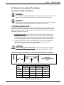
Refer to the diagram and table below for UH-200B and UH-100B power requirements.
208-240V
208-240V
120V
G
N
L1
Voltage
Hz
Phase
208-240/60/3
4 Wire Plus Ground System
Diagram
208-240V
L2
L3
40°F/22°C Rise Booster
70°F/39°C Rise Booster
Min. Wire Amp/
Min. Wire Amp/
Machine FLA Max. Fuse Size Machine FLA Max. Fuse Size
208/60/3
32.0
35/35
40.3
45/45
220/60/3
33.2
35/35
42.0
45/45
230/60/3
34.3
35/35
43.5
45/45
240/60/3
35.4
40/40
45.0
50/50
Three Phase Power Requirements
Models UH-200B and UH-100B Only
15
Part 2:
INSTALLATION
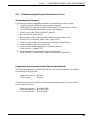
2.9 Chemical Connections
2.9.1 General (All Models)
!! ATTENTION DISHWASHER OWNER !!
Your dishwasher is designed to work best with liquid commercial dishwashing chemicals.
Detergents must be a commercial non-foaming liquid. Champion strongly recommends that
you contact a qualified chemical supplier to supply these products and to setup your machine for
the first time.
Your machine was shipped with the chemical dispensing adjustments set at their minimum
settings, because of variations in chemical products. As a result of these variations, Champion
is not able to advise you on the proper dispenser settings for any particular product nor can we
recommend one supplier over another. You may wish to consult your equipment dealer or your
Champion authorized service agent for help in contacting a chemical supplier in your area.
NOTE:
Residential automatic dishwashing detergents and rinse aids found in most grocery
stores are designed to work in machines with cycles of 15 minutes or longer.
Your Champion dishwasher cycle is complete in less than 3 minutes.
Champion does not recommend the use of residential automatic detergents and
rinse aid products. These products may accumulate in your machine and produce
poor washing results.
!
CAUTION:
Never use residential non-automatic dishwashing detergents such as JOY™ or
DAWN™, or any other liquid designed for the handwashing of wares, in your machine.
Extreme foaming inside your Champion dishwasher will cause operation problems.
NOTE:
FOR MODEL UL-100 ONLY
The UL-100 model is a low temperature dishwasher utilizing a chemical sanitizing final
rinse. Use a sodium hypochlorite (Chlorine) based sanitizer at a minimum
concentration of 50 PPM in the final rinse. Use chlorine test papers to verify and
monitor the 50 PPM chlorine level. (Consult local authority in Canada for proper
concentration).
Some metals, including silver, aluminum, and pewter, are attacked by
sodium hypochlorite (chlorine sanitizer). Avoid washing these metals
in a UL-100 model dishwasher.
16
Part 2:
INSTALLATION
2.9.1 General (All Models) Cont.
NOTE:
The detergent and rinse aid chemical dispensing pumps are optional equipment on
Models UH-200B, UH-200, UH-100B, and UH-100 dishwashers. The pumps may
have been specified when the dishwasher was ordered and installed at the factory.
The following instructions assume that your dishwasher was delivered to your
installation site with the dispensing pumps installed and explains the procedures for
placing the chemical dispensing system in service for the first time.
If optional pump(s) are not installed, Refer to Section 2.10, Installing Optional
Chemical Pumps, to install the chemical pump(s) before proceeding with
Sections 2.9.2 through 2.9.4.
Three chemical dispensing pumps (detergent, rinse aid, and sanitizer) are standard
on the UL-100 model.
!! ATTENTION CHEMICAL SUPPLIER !!
WARNING:
The instructions contained in Sections 2.9.2 through 2.9.4 require adjustments to the
Fill/Chemical Dispenser Circuit Board located inside the top mounted slide-out
control cabinet. When working on the dishwasher, disconnect the electrical service and
place a red tag at the disconnect switch to indicate work is being done on that circuit.
NOTE:
Refer to Part 7, Solid State Circuit Board Set-up and Repair, Section 7.3.5, page 66,
Fill/Chemical Dispenser Board, before making any adjustments to the dispenser
board settings.
.
Perform the following steps in preparation for making dispenser pump adjustments.
1. Loosen – do not remove – the (2) retaining screws at the bottom of the lower front access
panel. Lift the lower panel up and forward to remove.
2. Check for chemical dispensing pump(s) located at the front of the machine base.
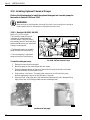
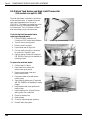
3. Refer to Fig. 2.9.1.
Open the dishwasher door.
4. Locate the two screws, one in each corner
FILL/CHEMICAL
of the top hood, that retain the slide-out
DISPENSER BOARD
control cabinet.
5. Remove the screws and pull the slide-out
cabinet forward to gain access to the
Fill/Chemical Dispenser Circuit Board.
(continued on next page)
Figure 2.9.1
Control Cabinet
Retaining Screws
17
Part 2:
INSTALLATION
2.9 Chemical Connections (Cont.)
2.9.1 General (All Models) Cont.
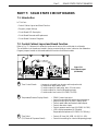
!! ATTENTION CHEMICAL SUPPLIER !! (continued from previous page)
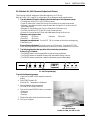
6. Refer to Fig. 2.9.2 showing the Fill/Chemical Dispenser Circuit Board.
7. There are (4) adjustable potentiometers.
• Fill2 to 40 seconds
4 5 6
7
3
• Detergent1 to 30 seconds
2
8
• Sanitizer1 to 30 seconds
1
9
• Rinse aid1 to 30 seconds
0
10
8. Two dots on one end of the potentiometer
serve as the dial pointer.
DOTS ON END
OF POTENTIOMETER
9. Turn CW to increase time setting.
3
4
5
0
The graduated numbers
(0-10) around the potentiometers
DO NOT correspond to time settings.
Use them for position reference only,
not an actual time setting indication.
4
7
5
6
3
10
FILL
NOTE:
6
8 2
9 1
2
1
0
7
3
8 2
9 1
10
DETERGENT
0
4
5
6
7
3
4
5
6
8 2
9 1
10
SANITIZER
7
8
9
0
10
RINSE
AID
Figure 2.9.2
Fill/Chemical Dispenser Circuit Board
Refer to Sections 2.9.2 through 2.9.4 for specific adjustments and chemical
priming instructions for your model dishwasher.
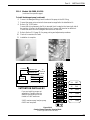
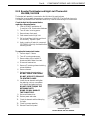
10. Refer to Fig. 2.9.3. showing the recommended chemical bottle placement.
Bottles may be placed on either side of the dishwasher.
11. Bottles must be placed no farther than
6 ft. [1829mm] from the machine.
12. I.D. tags identify chemical tubing.
13. Pick-up tubes are inserted directly
in chemical bottles.
I.D.TAG
Route chemical tubing
through rear access
hole above fill and
drain hose access
INSERT PICK-UP
TUBE IN BOTTLE
cut away
to show rear
Max.
6 ft.
[1829mm]
Floor
Figure 2.9.3
Chemical Bottle Placement
18
Part 2:
INSTALLATION
2.9.2 Models UH-200B, UH-200 (Chemical Adjust and Prime)
The following chemical adjustment information applies to UH-200B and UH-200 only.
Refer to Section 2.9.1, page 18, for a description of the dispenser adjust potentiometers.
1. The data below will assist in adjusting the time settings for the dispenser pumps:
• The wash tank holds 3.6 US gal. [13.6 liters] of water.
• Initial fill receives three doses of detergent from the detergent pump.
• Detergent is injected in the wash tank through a fitting at the rear of the wash tank.
• Detergent is injected during the first 1 to 16 seconds of the wash cycle.
• The final rinse utilizes 1.1 US gal [4.2 liters] of water per rack.
• Rinse aid is injected into the final rinse manifold. The manifold is located
in the top left rear corner of the dishwasher.
• Rinse aid is injected during the last 11 seconds of the final rinse cycle.
Dispenser pump output rates:
• Detergent69 ml/min.
• Rinse aid35 ml/min.
Detergent time adjustment- Turn the POT CW to increase run time from the beginning
of the wash cycle.
Rinse aid time adjustment- The final rinse cycle is 11 seconds. Turning the POT CW
moves the pump start point backward from the end of the rinse cycle.
2. The following describes the operation of the chemical prime button.
Refer to Fig. 2.9.4 below.
• The POWER button must be pushed ON to operate the prime button.
• The PRIME button is enabled whenever the temperature display is active.
• The PRIME button operates both dispensing pumps at the same time.
WASH
Champion
RINSE
POWER
START
EXTENDED
WASH
160 F
TEMPERATURE
PRESSURE
PRIME
Figure 2.9.4
UH-200B, UH-200 Touchpad/Display
To prime the detergent and rinse aid pumps:
3. Insert pick-up tubes in the chemical bottles.
4. Push POWER button ON.
Machine fills. Temperature is displayed.
5. Open dishwasher door and observe detergent
injection point on rear wall of machine.
6. Push and hold PRIME button until detergent is
observed entering the machine.
7. Push and hold the PRIME button and observe
chemical flowing at the rinse aid injection point
located in the final rinse manifold.
8. Priming is complete.
Rinse aid
injection point
Final rinse
manifold
Figure 2.9.5
Rinse aid injection point
Models UH-200B, UH-200
19
Part 2:
INSTALLATION
2.9.3 Models UH-100B, UH-100 (Chemical Adjust and Prime)
The following chemical adjustment information applies to UH-100B and UH-100 only.
Refer to Section 2.9.1, page 18, for a description of the dispenser adjust potentiometers.
1. The data below will assist in adjusting the time settings for the dispenser pumps:
• The wash tank holds 1.8 US gal. [6.8 liters] of water.
• Proper fill water level is even with the bottom of the round scrap screen.
• Detergent and rinse aid enter the wash tank through the fill chute on the left side of the
machine.
• Detergent is injected during the first 1 to 16 seconds of the wash cycle.
• The final rinse utilizes 1.8 US gal [6.8 liters] of water per rack.
• Rinse aid is injected as the fill/rinse valve adds water during the final rinse.
Dispenser pump output rates:
• Detergent69 ml/min.
• Rinse aid69 ml/min.
Detergent time adjustment- Turn the POT CW to increase run time from the beginning
of the wash cycle.
Rinse aid time adjustment- The final rinse cycle is 15 seconds. Turning the POT CW
moves the pump start point backward from the time the fill valve closes for the final rinse.
2. The following describes the operation of the chemical prime buttons.
Refer to Fig. 2.9.6 below.
• The POWER button must be pushed ON to operate the prime button.
• The PRIME button is enabled whenever the temperature display is active.
• The PRIME button operates both dispensing pumps at the same time.
160 F
Champion
POWER
START
EXTENDED
WASH
TEMPERATURE
PRIME
Figure 2.9.6
UH-100B, UH-100 Touchpad/Display
To prime the detergent and rinse aid pumps:
3. Insert pick-up tubes in the chemical bottles.
4. Push POWER button ON.
Machine fills. Temperature is displayed.
5. Open dishwasher door and observe
fill chute on left inside of machine.
6. Push and hold PRIME button until detergent and rinse aid
are observed entering the interior of the machine.
Rinse aid is usually blue in color, hold PRIME button
until the colored liquid is detected.
7. Priming is complete.
Figure 2.9.7
Fill Chute
Models UH-100B, UH-100, UL-100
20
Part 2:
INSTALLATION
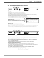
2.9.4 Models UL-100 (Chemical Adjust and Prime)
The following chemical adjustment information applies to UL-100 only.
Refer to Section 2.9.1, page 18, for a description of the dispenser adjust potentiometers.
1. The data below will assist in adjusting the time settings for the dispenser pumps:
• The wash tank holds 2.5 US gal. [10 liters] of water.
• Proper fill water level is even with the top of the handle on the round scrap screen.
• Detergent, rinse aid and sanitizer enter the wash tank through the fill chute on the left
side of the machine.
• Detergent is injected during the first 1 to 18 seconds of the wash cycle.
• The final rinse utilizes 2.3 US gal [8.7 liters] of water per rack.
• Rinse aid is injected as the fill/rinse valve adds water during the final rinse.
Dispenser pump output rates:
• Detergent69 ml/min.
• Sanitizer69 ml/min
• Rinse aid69 ml/min.
Detergent time adjustment- Turn the POT CW to increase run time from the beginning
of the wash cycle.
Rinse aid time adjustment- The final rinse cycle is 15 seconds. Turning the POT CW
moves the pump start point backward from the time the fill valve closes for the final rinse.
2. The following describes the operation of the chemical prime buttons.
Refer to Fig. 2.9.8 below.
• The POWER button must be pushed ON to operate the prime buttons.
• The PRIME buttons are enabled whenever the temperature display is active.
• The PRIME buttons operate their respective dispenser pumps independently.
PRIME
140 F
Champion
POWER
START
EXTENDED
WASH
TEMPERATURE
DETERGENT
SANITIZER
RINSE AID
Figure 2.9.8
UL-100 Touchpad/Display
To prime the dispensing pumps:
3. Insert pick-up tubes in their respective chemical
bottles.
4. Push POWER button ON.
Machine fills. Temperature is displayed.
5. Open dishwasher door and observe
fill chute on left inside of machine.
6. Push and hold each PRIME button in succession
• Detergent
• Rinse aid
• Sanitizer
7. Observe that each chemical enters the machine.
8. Priming is complete.
4-2
Figure 2.9.9
Fill Chute Discharge
Models UH-100B, UH-100, UL-100
21
Part 2:
INSTALLATION
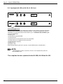
2.10 Installing Optional Chemical Pumps
Perform the following steps to install the optional detergent and rinse aid pumps for
the models in Sections 2.10.1 and 2.10.2
WARNING:
When working on the dishwasher, disconnect the electric service and place a red tag at
the disconnect switch to indicate work is being done on that circuit.
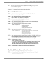
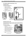
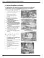
2.10.1 Models UH-200B, UH-200
Refer to Fig. 2.10.1 at right.
The illustration shows the typical
installation of the detergent and
rinse aid pumps. Pump kits contain
the necessary parts for field installation
and are available from your authorized
Champion parts supplier.
Signal connection
points: 2A Max @
120VAC
• The detergent pump is a peristaltic
pump enclosed in a black housing.
• The rinse aid pump is a peristaltic
pump enclosed in a black housing..
Route tubing
Rinse aid
Detergent
Figure 2.10.1
UH-200B, UH-200 Chemical Pumps
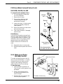
To install the detergent pump:
1. Remove the lower front access panel.
2. Mount the pump on the machine base with two screws.
3. Route the detergent tubing out the rear of the machine through the access hole located
above and between the fill and drain hoses.
4. Pump rotation is clockwise. The supply tube connects on the left side of the pump
the discharge tubing connects on the right side of the pump.
5. Remove the 1/8" plug at the rear of the machine and replace with the 90° detergent fitting.
Apply teflon tape to the fitting threads to ensure a watertight seal.
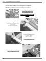
4-9
4-16
(continued of next page)
22
Part 2:
INSTALLATION
2.10.1 Models UH-200B, UH-200
(continued from previous page)
To install the detergent pump (continued):
6. Connect the detergent tubing from the outlet of the pump to the 90° fitting
7. Connect the pump motor wires to the harness wires supplied in the installation kit.
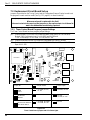
8. Refer to Fig. 2.10.2 below.
Connect the wiring harness to the 10 pin terminal block located on the lower right side of
the machine. Connect the #2 harness wire to the Common (#2) terminal on the block.
Connect the #24 wire to the Detergent #24 terminal on the block.
9. Refer to Section 2.9.2, page 19, for pump priming and adjustment procedures.
10. Check all connections for leaks.
11. Installation is complete.
4-10
Common
Harness #2
Harness # x
Hot
PUMP
MOTOR
#x=
Detergent
Rinse aid
Sanitizer
H04
To
Terminal
Block
#24
#25
#26
!!ATTENTION INSTALLER!!
If you are installing pumps not
supplied by Champion then the
chemical connection points are
limited to 2 AMP maximum.
2 AMP maximum amp load per pump;
6 AMP total amp load.
4
4
6
6
54
54
24
24
24
DET
25
25
25
R/A
26
26
26
SANI
2
2
2
COM
2
2
2
COM
2
2
2
COM
Figure 2.10.2
Chemical Pump Connection Terminal Block
(Lower right side of machine base)
23
Part 2:
INSTALLATION
2.10 Installing Optional Chemical Pumps (Cont.)
2.10.1 Models UH-200B, UH-200
To install the rinse aid pump:
1. Remove the lower front access panel.
2. Mount the pump on the machine base with two screws.
3. Route the rinse aid tubing out the rear of the machine through the access hole located
above and between the fill and drain hoses.
4. Pump rotation is clockwise. The supply tube connects on the left side of the pump;
the discharge tubing connects on the right side of the pump.
5. Remove the 1/8" plug located in the final rinse manifold.
6. Install the rinse aid check valve. Apply teflon tape to the valve threads to ensure a seal.
7. Route the rinse aid tubing to the rinse manifold and connect to the check valve.
8. Connect the pump motor wires to the harness wires supplied in the kit with wire nuts.
9. Refer to Fig. 2.10.2 on page 23.
Connect the wiring harness to the 10 pin terminal block located on the lower right side of
the machine. Connect the #2 harness wire to the Common (#2) terminal on the block.
Connect the #25 wire to the rinse aid #25 terminal on the block.
10. Refer to Section 2.9.2, page 19, for pump priming and adjustment procedures.
11. Check all connections for leaks.
12. Installation is complete.
4-16
4-5
24
4-4
4-6
Part 2:
INSTALLATION
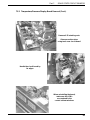
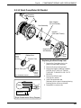
2.10.2 Models UH-100B, UH-100
Chemical discharge tubes were installed at the factory and stowed in the base of the machine.
Installation of the optional detergent pump and/or the rinse aid pump requires mounting
the pump, connecting all tubing to the pump(s) and making the electrical connections.
WARNING:
When working on the dishwasher, disconnect the electric service and place a red tag at
the disconnect switch to indicate work is being done on that circuit.
Refer to Fig. 2.10.3 at right.
The illustration shows the typical
installation of the detergent and
rinse aid pumps. Pump kits contain
the necessary parts for field installation
and are available from your authorized
Champion parts supplier.
Signal connection
points: 2A Max @
120VAC
• The detergent pump is a peristaltic
pump enclosed in a black housing.
Route tubing
• The rinse aid pump is a peristaltic
pump enclosed in a black housing.
Rinse aid
Detergent
Figure 2.10.3
UH-100B, UH-100 Chemical Pumps
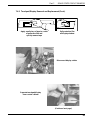
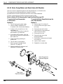
To install the detergent pump:
1. Remove the lower front access panel.
2. Mount the pump on the machine base with two screws.
3. Route the detergent pick-up tube and tubing out the rear of
the machine through the access hole located above and
between the fill and drain hoses.
4. Connect the supply and discharge tubing to the pump.
Pump rotation is clockwise. The supply tube connects on the
left side of the pump; the discharge tubing connects on the right
side of the pump.
5. Chemical discharge tubing runs to the fill chute assembly
located on the left side of the machine.
6. The fill chute discharge is
located on the left interior
wall of the wash chamber.
1-9A
(continued of next page)
4-16
4-2
25
Part 2:
INSTALLATION
2.10 Installing Optional Chemical Pumps (Cont.)
2.10.2 Models UH-100B, UH-100
(continued from previous page)
To install the rinse aid pump:
1. Remove the lower front access panel.
2. Mount the pump on the machine base with two screws.
3. Route the pick-up tube and rinse aid supply tubing out the rear of the machine through the
access hole located above and between the fill and drain hoses.
4. Pump rotation is clockwise. The supply tube connects on the left side of the pump;
the discharge tubing connects on the right side of the pump.
5. The rinse aid discharge tubing is preinstalled and is marked by a blue tag.
Connect the discharge tubing to the pump using a tie wrap supplied in the kit.
6. Connect the supply tubing to the left side of the pump and route the pick-up tube to the
chemical container.
7. Connect the pump motor wires to the harness wires supplied in the kit with wire nuts.
8. Refer to Fig. 2.10.2 on page 23.
Connect the wiring harness to the 10 pin terminal block located on the lower right side of
the machine. Connect the #2 harness wire to the Common (#2) terminal on the block.
Connect the #25 wire to the rinse aid #25 terminal on the block.
9. Refer to Section 2.9.2, page 20, for pump priming and adjustment procedures.
10. Check all connections for leaks.
11. Installation is complete.
2.11 Initial Start-up
(All Models)
Review Part 2, Installation, Sections 2.2 through 2.10, to ensure that all plumbing, electrical,
and chemical connections have been properly made by qualified personnel.
√
Plumbing connections are the proper size and supply pressures are correct.
• Water supply is on.
• Drains are correct size and functional.
√
Electrical power requirements and wiring connections are correct.
• Power is on at the main service panel.
√
Chemical Dispensing systems are installed and chemical supplies replenished.
• Detergent and rinse aid for Models UH-200B, UH-200, UH-100B, UH-100.
• Detergent, rinse aid, and sanitizer for Model UL-100.
(See next page)
26
Part 2:
INSTALLATION
Review Part 3, Daily Operation, Sections 3.1 through 3.5, for instructions on the operation
of your dishwasher, then perform the following checks for your model machine:
2.11.1 Models UH-200B, UH-200 (Initial Start-up)
Water Level Probe
√
Push the POWER button.
• 888F, and LED's flash on display
• No error codes (E0, E1, E2, E3)
• Machine fills
• Detergent pump runs (if applicable)
√
Open door and check water level in tank
• Water level at middle sensor of water level probe.
Probe located on interior left side of dishwasher.
• Close door.
• Check for leaks around dishwasher.
√
Run a cycle without dishes to bring the machine to operating temperature.
• 150°F/66°C
√
Push START button.
• Check for leaks.
• Dishwasher completes normal cycle.
• Final rinse temperature reaches minimum of 180°F/82°C.
√
Push POWER button.
• Displays flash 888F
• Dishwasher completes normal auto-shutdown cycle.
• Check for leaks in drain piping.
√
Push the POWER button.
• Machine fills again.
√
Push START button.
• Machine begins cycle
√
Push EXTENDED WASH button.
• Wash cycle holds in continuous wash mode
• Extended wash LED illuminates.
√
Push EXTENDED WASH button.
• Wash cycle returns to normal wash mode
• Extended wash LED goes out.
• Normal cycle completed.
√
Water
Level
Push POWER button.
• Displays flash 888F
• Dishwasher completes normal auto-shutdown cycle.
• Initial Start-up is complete.
27
Part 2:
INSTALLATION
2.11 Initial Start-up (Cont.)
2.11.2 Models UH-100B, UH-100, UL-100
3
√
√
Open door and check water level in tank
• (UH-100B, UH-100) Water level even
with the bottom of the round scrap screen
• (UL-100) Water level even with the
top of the handle on the round scrap screen
5
6
7
2
1
8
9
0
10
3
4
5
6
4
7
2
3
8 2
9 1
1
0
10
FILL
DOTS ON END
OF POTENTIOMETER
0
5
6
7
3
4
5
8 2
9 1
10
DETERGENT
0
3
4
5
6
8 2
9
10
7
8
1
9
0
10
RINSE
AID
Refer to Part 7, Section 7.3.5,
pages 66-67, for instructions
on adjusting the fill water
level for Models UH-100B,
UH-100, and UL-100
dishwashers.
√
Check wash tank minimum operating temperature.
• (UH-100B, UH-100) minimum 150°F/66°C.
• (UL-100) minimum 120°F/49°C, optimum 140°F/60°C.
√
Push START button.
• Check for leaks.
• Dishwasher completes normal cycle.
• Final rinse temperature reaches minimum of 180°F/82°C for UH-100B, UH-100.
• Final rinse temperature maintains minimum of 120°F/49°C for UL-100.
√
Push POWER button.
• Displays flash 888F
• Dishwasher completes auto-shutdown cycle.
• Check for leaks in drain piping.
√
Push the POWER button.
• Machine fills again.
√
Push START button.
• Machine begins cycle
√
Push EXTENDED WASH button.
• Wash cycle holds in continuous wash mode
• Extended wash LED illuminates.
√
7
NOTE:
Close door.
• Check for leaks around dishwasher.
Push EXTENDED WASH button.
• Wash cycle returns to normal wash mode
• Extended wash LED goes out.
• Normal cycle completed.
6
SANITIZER
√
√
28
Push the POWER button.
• 888F, and LED's flash on display
• No error codes (E0, E1, E2)
• Machine fills, LO display is normal.
• Detergent pump runs (if applicable)
4
UH-100B, UH-100
Water Level
Halfway up the
sloped angle of
screen handle
UL-100
Water Level
even with top
of screen handle
Push POWER button.
• Displays flash 888F
• Dishwasher completes normal auto-shutdown cycle.
• Initial Start-up is complete.
Part 3:
DAILY OPERATION
PART 3: DAILY OPERATION
3.1 Introduction
In This Part—
• Preparing your Dishwasher
• Dishwasher Loading
• Description of Operator Controls
• Basic Operation
3.2 Preparing your Dishwasher (All Models)
Review Part 2, Installation, and check your site to ensure that all plumbing and electrical
connections have been properly made by qualified personnel.
Check the installation of chemical dispensing systems, if applicable.
Perform the following steps to prepare your machine for operation.
1. Check the exterior of the machine for any foreign material and remove.
2. Check the interior of the machine and remove any foreign material.
3. Remove the lower spray arm(s) and the round scrap screen.
4. Make sure the pump intake strainer located in the bottom of the sump is in place and clean.
5. Replace the round scrap screen and clean if required.
6. Make sure the upper and lower spray arms are in place and nozzles are clean.
The arms are held in place by knurled retaining screws. The arms are interchangeable.
• Models UH-200B, and UH-200 have separate upper and lower wash
and upper and lower rinse arms.
• Models UH-100B, UH-100, and UL-100 have upper and lower wash arms.
7. Check the chemical supply containers, and fill as required.
8. Open the water supply valve. Check for leaks and take corrective action as required.
9. Check the drain and/or drain connections to ensure drains are functional.
10. Turn the main power on at the breaker panel or fused disconnect switch.
Knurled retaining screw
Pump Intake
Screen
All Models
UH-100B, UH-100, UL-100 Shown
29
Part 3:
DAILY OPERATION
3.3 Loading your Dishwasher (All Models)
Perform the following steps to prepare and load your wares for washing.
1. Scrape and rinse wares to remove heavy food particles
and other debris.
2. Place dishes edgewise in a peg rack.
Place cups and bowls upside down in a flat rack.
Spread silverware evenly in a single layer in a
flat bottom rack.
Batching silverware upright
in a utensil cup is not recommended.
DO NOT OVERLOAD DISHRACKS.
3. Place the loaded dishrack
on the open door and slide
into the dishwasher.
Champion
POWER
START
EXTENDED
WASH
TEMPERATURE
PRESSURE
Champion
PRIME
POWER
START
EXTENDED
TEMPERATURE
WASH
PRIME
PRESSURE
DO NOT WASH
MORE THAN ONE
RACK AT A TIME.
Champion
POWER
CAUTION:
!
30
Never stand or sit on the door, nor place
heavy boxes or crates on the door.
START
EXTENDED
WASH
TEMPERATURE
PRESSURE
PRIME
Part 3:
DAILY OPERATION
3.4 Description of Operator Controls and Displays
Note the location and function of the following
components. These components directly
affect the normal operation of all other
operator controls.
Door Safety Switch Magnet:
The door safety switch magnet is located
at the top left inside corner of the door.
The magnet operates the door safety switch
located in the top mounted slide-out control
cabinet.
The door must be fully closed whenever the
dishwasher is in an automatic cycle.
Door
Magnet
NOTE:
The dishwasher will not operate when the
POWER button is pushed, if the door is
open on initial power up.
Figure 3.4.1
Door Safety Magnet Location
Control Circuit Breaker
The 8 AMP control circuit breaker is located
on the left lower side of the dishwasher
behind the lower front access panel.
The circuit breaker is designed to trip and
break the 120VAC control voltage to the
dishwasher in the event of an overload
or other abnormal condition. This
protects the dishwasher's solid state
circuitry.
The circuit breaker must be reset manually.
The dishwasher will not operate if the
circuit breaker has tripped.
Circuit
Breaker
Figure 3.4.2
Circuit Breaker Location
31
Part 3:
DAILY OPERATION
3.4 Description of Operator Controls and Displays (Cont.)
Refer to the illustrations and table below for the location and function of the operator
controls and displays.
Touchpad/Display
2
4
6
7
9
11
10
WASH
Champion
RINSE
POWER
1
START
3
2
EXTENDED
WASH
5
4
TEMPERATURE
UH-200B, UH-200
8
6
PRIME
PRESSURE
11
9
Champion
POWER
1
START
3
2
EXTENDED
WASH
UH-100B, UH-100
5
4
PRIME
TEMPERATURE
6
11
9
PRIME
Champion
POWER
1
32
START
3
EXTENDED
WASH
5
TEMPERATURE
DETERGENT
SANITIZER
RINSE AID
UL-100
Part 4:
CONTROL
TYPE
1
Power
ON/OFF
Switch
2 Power
ON LED
3 Start Switch
4 Cycle ON LED
Touchpad
membrane
switch
Touchpad light
emitting diode
Touchpad
membrane
switch
Touchpad light
emitting diode
DAILY OPERATION
DESCRIPTION OF OPERATION
All Models:
Power is OFF. Push Power Button—
Activates the solid state controls and begins
automatic fill operation.
Power is ON. Push Power Button—
Begins auto-shutdown cycle. Turns power OFF
when auto-shutdown cycle is complete.
All Models:
Indicates when power is ON.
All Models:
Starts the dishwasher automatic cycle.
All Models:
Indicates an automatic cycle has been selected.
5 Extended
Wash
Switch
Touchpad
membrane
switch
All Models:
Pauses the wash cycle and holds machine in a
continuous wash mode. Push again, machine
finishes wash cycle followed by a final rinse.
6 Extended
Wash LED
Touchpad light
emitting diode
All Models:
Indicates machine is in extended wash mode.
Touchpad
light
emitting diode
Model UH-200B, UH-200 ONLY:
Indicates that temperature display (9) is showing
the temperature of the water in the wash tank
during the automatic cycle.
Touchpad
light
emitting diode
Model UH-200B, UH-200 ONLY:
Indicates that temperature display (9) is showing
the temperature of the water in the final rinse
manifold during a final rinse.
7 Wash
Temperature
LED
8 Rinse
Temperature
LED
9 Temperature
Display
10 Final Rinse
Water Pressure
Display
11 Chemical
Pump
Prime
Switch(es)
LED
display
mounted on
timer board
All Models:
Indicates the temperature sensed by the wash
or the final rinse temperature probe.
LED
display
mounted on
timer board
Model UH-200B, UH-200 ONLY:
Indicates the flowing pressure of water in the
final rinse manifold during the final rinse cycle.
Min./Max. 20-22 PSI [138-151 kPa].
Touchpad
membrane
switch(es)
All Models:
Operates the chemical pumps whenever (9) is
activated. UH-200B, UH-200, UH-100B, UH-100
single switch operates both pumps at same time.
UL-100 each prime switch operates its pump
independently.
33
Part 3:
OPERATION
3.5 Basic Operation
The following illustrations and diagrams describe the basic operation of your dishwasher.
Review Sections 3.2 and 3.3 before operating your machine.
NOTE:
All temperature readings in the instructions below are given in degrees Fahrenheit (°F).
Pressure readings are given in pounds per square inch (PSI).
All models provide a metric option to display temperature in degrees Celsius (°C)
and pressure in kilopascals (kPa). Temperature readings and error codes are followed
by the letter "C" when the metric option is enabled.
3.5.1 Operating the UH-200B and UH-200
WASH
Champion
RINSE
POWER
START
EXTENDED
WASH
LO
TEMPERATURE
PRESSURE
PRIME
Push the POWER Button:
All LEDs illuminate and 888F flash on displays.
Internal diagnostics displays Error Codes: E1, E2, E3 in temperature display if problem exists.
Power LED lit. LOF displayed if wash temp is below 115°F, actual wash temp displayed above 115°F/46°C.
PRIME button is active whenever the temperature is displayed.
Machine Fills. Optional detergent pump injects detergent.
Wash tank heat on (UH-200B, UH-200). Booster heat on (UH-200B only).
Wash LED illuminates indicating the temperature display is reading wash tank temperature.
WASH
Champion
RINSE
POWER
START
EXTENDED
WASH
150 F
TEMPERATURE
PRESSURE
PRIME
(If the START button is pushed during initial fill the Start LED will illuminate indicating that a cycle has
been selected but the machine will complete the fill before the cycle begins.
Run one automatic cycle WITHOUT DISHES to bring the dishwasher to operating temperature.
Push the START Button:
The Start LED illuminates and the automatic 90-second cycle begins. Detergent pump adds detergent.
Wash pump runs for 60 seconds.
Wash pump stops, machine drains a portion of the water out of the wash tank.
WASH
Champion
RINSE
POWER
START
EXTENDED
WASH
180 F
TEMPERATURE
20
PRESSURE
PRIME
Rinse LED illuminates indicating the temperature display is reading final rinse temperature.
Final rinse operates for 11 seconds. Optional rinse aid pump injects rinse aid.
Final rinse temperature 180°F/82°C minimum. Final rinse flowing pressure 20 PSI/138 kPa minimum.
Pressure display indicates final rinse flowing pressure.
Rinse LED goes out. Start LED goes out. Automatic cycle is complete.
Open door, remove rack, insert another rack and repeat.
Opening the door anytime during the cycle pauses the cycle. Cycle resumes where it stopped when door
is closed. Pushing the POWER button stops the cycle and initiates the AUTO-SHUTDOWN CYCLE.
34
Part 3:
DAILY OPERATION
3.5.1 Operating the UH-200B and UH-200 (Cont.)
WASH
Champion
RINSE
POWER
START
EXTENDED
WASH
150 F
TEMPERATURE
PRESSURE
PRIME
EXTENDED WASH FEATURE
The EXTENDED WASH button pauses the normal wash cycle and holds the dishwasher in a continuous
wash mode until the extended wash button is pushed again. To activate the extended wash feature:
Push the START button to begin a cycle.
WAIT 16 seconds to allow the optional detergent pump time to inject detergent.
Push the EXTENDED WASH button.
The Extended Wash LED illuminates. The Power LED remains lit, the Start LED remains lit.
Dishwasher is held in continuous wash mode.
Push the EXTENDED WASH button again.
The Extended Wash LED goes out. The Power LED remains lit, the Start LED remains lit.
If the extended wash is deactivated before the 60-second wash cycle is complete, the dishwasher will
complete the normal wash cycle, drain and finish with a final rinse.
If the extended wash is deactivated after the 60-second wash cycle time has elapsed, then the
dishwasher will immediately drain, and finish with a final rinse.
WASH
Champion
RINSE
POWER
START
EXTENDED
WASH
TEMPERATURE
WASH
Champion
RINSE
POWER
START
EXTENDED
WASH
150 F
PRESSURE
PRIME
888F 888
TEMPERATURE
PRESSURE
PRIME
AUTO-SHUTDOWN CYCLE
At the end of the day, pushing the POWER button initiates the Auto-shutdown cycle which includes an
automatic interior rinse down to aid in cleaning the machine. Pushing the POWER button when the
dishwasher is in cycle also will start the auto shutdown cycle. To activate the auto shutdown cycle:
Push the POWER button.
All LED's go out.
The Temperature display and the Pressure display flash 888F.
The machine drains.
The fill valve opens to rinse down the interior of the dishwasher.
The machine drains completely.
All displays go out.
Dishwasher is OFF.
Begin cleaning operation or push POWER button to refill dishwasher.
NOTE:
If the dishwasher is idle for more than 4 hours, it will automatically enter the
auto-shutdown cycle.
This completes the basic operation for the UH-200B and UH-200.
35
Part 3:
DAILY OPERATION
3.5 Basic Operation (Cont.)
NOTE:
All temperature readings in the instructions below are given in degrees Fahrenheit (°F).
Pressure readings are given in pounds per square inch (PSI).
All models provide a metric option to display temperature in degrees Celsius (°C)
and pressure in kilopascals (kPa). Temperature readings and error codes are followed
by the letter "C" when the metric option is enabled.
3.5.1 Operating the UH-100B and UH-100, and UL-100
LO
Champion
POWER
START
EXTENDED
WASH
PRIME
TEMPERATURE
Push the POWER Button:
All LEDs illuminate and 888F flash on displays.
PRIME
Internal diagnostics displays Error Codes: E0, E1, E2 in temperature
display if problem exists.
DETERGENT SANITIZER RINSE AID
Power LED lit. LOF displayed if wash temp is below 115°F, actual wash temp
displayed above 115°F/46°C.
PRIME button(s) are active whenever the temperature is displayed.
(UL-100 has three PRIME buttons)
Machine Fills.
Wash tank heat on (UH-100B, UH-100). Booster heat on (UH-100B only).
Model UL-100 does not have tank heat.
(140 °F/60 °C for UL-100)
150 F
Champion
POWER
START
EXTENDED
WASH
TEMPERATURE
PRIME
(If the START button is pushed during initial fill the Start LED will illuminate indicating that a cycle has been
selected but the machine will complete the fill before the cycle begins.
Model UH-100B, UH-100
Run one automatic cycle WITHOUT DISHES to bring the dishwasher to operating temperature.
UH-100B, UH-100 minimum wash temperature of 150 °F/66 °C.
UL-100 minimum wash temperature is 120°F/49°C. The optimum temperature for UL-100 is 140 °F/60°C.
Push the START Button:
The Start LED illuminates and the automatic cycle begins. Detergent pump adds detergent.
Wash pump runs.
Wash pump stops, machine drains the water out of the wash tank.
(continued on next page)
36
Part 3:
DAILY OPERATION
3.5.1 Operating the UH-100B and UH-100, UL-100 (Cont.)
180 F
Champion
POWER
START
EXTENDED
WASH
(140 °F/60 °C for UL-100)
PRIME
TEMPERATURE
Drain Stops.
Fill/Rinse valve opens and hot water enters the wash tank.
(UH-100B, UH-100 Optional rinse aid pump injects rinse aid.)
(UL-100 ONLY Standard rinse aid pump injects rinse aid. Standard sanitizer pump injects sanitizer.)
Temperature display indicates temperature of the final rinse water.
Final rinse temperature 180°F/82°C minimum for UH-100B, UH-100.
Final rinse temperature 120°F/49 °C minimum, 140°F/60°C optimum for UL-100.
Wash pump runs for 3 seconds and stops.
Fill/Rinse valve closes.
Wash pump runs again until final rinse cycle is complete.
}
The three second wash pump run time as
the fill/rinse valve adds final rinse water to
the wash tank removes air and makes
sure the wash pump pumps at maximum
capacity.
Wash pump stops
Start LED goes out. Automatic cycle is complete.
Open door, remove rack, insert another rack and repeat.
Opening the door anytime during the cycle pauses the cycle. Cycle resumes where it stopped when door
is closed. Pushing the POWER button stops the cycle and initiates the AUTO-SHUTDOWN CYCLE.
150 F
Champion
POWER
START
EXTENDED
WASH
(140 °F/60 °C for UL-100)
TEMPERATURE
PRIME
EXTENDED WASH FEATURE
The EXTENDED WASH button pauses the normal wash cycle and holds the dishwasher in a continuous
wash mode until the extended wash button is pushed again. To activate the extended wash feature:
Push the START button to begin a cycle.
WAIT 16 seconds to allow the optional detergent pump (standard on UL-100) time to inject detergent.
Push the EXTENDED WASH button.
The Extended Wash LED illuminates. The Power LED remains lit, the Start LED remains lit.
Dishwasher is held in continuous wash mode.
Push the EXTENDED WASH button again.
The Extended Wash LED goes out. The Power LED remains lit, the Start LED remains lit.
If the extended wash is deactivated before the wash cycle is complete, the dishwasher will complete the
normal wash cycle, drain and finish with a final rinse.
If the extended wash is deactivated after the normal wash cycle time has elapsed, then the
dishwasher will immediately drain, and finish with a final rinse.
(continued on next page)
37
Part 3:
DAILY OPERATION
3.5.1 Operating the UH-100B and UH-100, UL-100 (Cont.)
150 F
Champion
POWER
START
EXTENDED
WASH
POWER
START
EXTENDED
WASH
(140°F/60°C for UL-100)
TEMPERATURE
PRIME
888F
Champion
TEMPERATURE
PRIME
AUTO-SHUTDOWN CYCLE
At the end of the day, pushing the POWER button initiates the auto-shutdown cycle which includes an
automatic interior rinse down to aid in cleaning the machine. Pushing the POWER button when the
dishwasher is in cycle also will start the auto-shutdown cycle. To activate the auto-shutdown cycle:
Push the POWER button.
All LED's go out.
The Temperature display flash 888F.
The machine drains.
The fill valve opens to rinse down the interior of the dishwasher.
The wash pump runs to complete the interior rinse down.
The machine drains completely.
All displays go out.
Dishwasher is OFF.
Begin cleaning operation (See Part 4, page 39) or push POWER button to refill dishwasher.
NOTE:
If the dishwasher is idle for more than 4 hours, it will automatically enter the
auto-shutdown cycle.
This completes the basic operation for the UH-100B, UH-100 and UL-100.
38
Part 4:
CLEANING AND MAINTENANCE
PART 4: CLEANING AND MAINTENANCE
In This Part—
• Introduction
• Daily cleaning schedules
• Deliming procedure
• Preventive maintenance schedules
• Lubrication
4.1 Introduction
Cleaning your machine is the best maintenance that you can provide. Components that are not
regularly flushed and cleaned do not perform well.
The following schedules are the minimum requirements necessary for the proper performance of
your machine. Intervals should be shortened whenever your machine is faced with abnormal
working conditions, hard water, or multiple shift operations.
4.2 Daily Cleaning Schedules
Every 2 hours of operation and after each meal period
1.
2.
3.
4.
Drain the dishwasher.
Clean the round scrap screen and pump intake screen.
Check and clean the spray arms.
Reassemble the dishwasher.
At the End of the Day
1.
2.
3.
4.
!
Drain the machine.
Clean the round scrap screen and pump intake screen.
Clean spray arms.
Wipe the interior of the machine with a soft damp cloth.
CAUTION:
Do not hose down the exterior of the machine with water.
5. Thoroughly clean the exterior of machine with mild soap solution.
6. Reassemble the machine.
7. Leave door open to aid in drying the interior of the dishwasher.
39
Part 4:
CLEANING AND MAINTENANCE
4.3 Deliming Schedules (All Models)
Your dishwasher should be delimed regularly depending on the mineral content of your water. Inspect
the machine interior for mineral deposits (white residue) and use a deliming solution for the best
cleaning results.
WARNING:
Deliming solutions or other acids must not come in contact with household bleach
(sodium hypochlorite) or any chemicals containing chlorine, iodine, bromine, or fluorine.
Mixing will cause hazardous gases to form.
Skin contact with deliming solutions can cause severe irritation and possible chemical burns.
WARNING:
Consult your chemical supplier for an appropriate deliming solution, usage instructions,
protective gear and specific safety procedures.
The following general instructions are provided to assist the operator in deliming the dishwasher. In no case do these instructions supersede the chemical supplier's instructions in
the use of a specific deliming product.
4.1.2 Deliming Procedure (All Models)
1. Remove all racks and wares from the dishwasher.
2. Remove chemical pick-up tubes from the containers and place in a catch pan on the floor.
• UH-200B, UH-200, UH-100B, UH-100 may utilize detergent and rinse aid.
• UL-100 utilizes detergent, rinse aid, and sanitizer.
3. Push POWER button to enter auto-shutdown cycle if machine is already on.
4. Push POWER button again to fill machine.
5. Run four (4) automatic cycles to clear chemical from chemical supply tubing.
6. Push POWER button to enter auto-shutdown cycle and drain the machine completely.
7. Push POWER button to fill machine.
8. Open door and add deliming solution (per chemical supplier's instructions)
directly in wash tank.
• UH-200B, UH-200 hold 3.6 US gal. [13.6 liters] of water.
• UH-100B, UH-100 hold 1.8 US gal. [6.8 liters] of water.
• UL-100 holds 2.3 US gals. [8.7 liters] of water
9. Close door.
10. Push START button and immediately push EXTENDED WASH button.
11. Run machine in extended wash mode (per chemical supplier's recommended time).
12. Push EXTENDED WASH button to exit extended wash mode.
Machine will complete automatic cycle.
13. Open door and inspect interior for mineral deposits. Repeat steps 3-11 if required.
14. Run four (4) additional cycles to flush all deliming chemicals from machine.
15. Replace chemical pick-up tubes in containers and prime the chemical dispensing system.
16. Deliming is complete.
40
Part 4:
CLEANING AND MAINTENANCE
4.4 Preventive Maintenance Schedules
Daily Maintenance Requirements
Perform the following procedures every day.
1. Check the chemical supply containers and replenish as needed.
2. Inspect scrap screens for bent or damaged parts.
3. Check the spray arm bearings and make sure arms turn freely.
Weekly Maintenance Requirements
Perform the following procedures every week.
1. Inspect for leaks including all piping and supply connections.
Tighten or repair as required.
2. Inspect the door and door gasket for proper fit and ease of operation.
3. Check the operation of the door safety switch.
4. Check the flexible water supply and drain hoses at the rear of machine to ensure they
are not kinked.
5. Place chemical pick-up tubes in containers of hot water to flush crystallized chemical from
the supply tubing.
Semi-Annual Maintenance Requirements
Perform the following procedures every six months.
1. Inspect all chemical connections and supply tubing for leaks.
2. Check the building drain system and clean as needed.
Yearly Maintenance Requirements
Perform the following procedures every year.
1. Inspect the installation site for cleanliness and any foreign material around the machine.
Clean as required.
2. Check the overall condition of the machine. Replace any worn or damaged parts.
4.5 Lubrication
There are no lubrication points on the dishwasher.
Pump motor bearings are sealed and require no lubrication.
41
Part 5:
OPERATOR TROUBLESHOOTING
This Page
Intentionally
Left
Blank
42
Part 5:
OPERATOR TROUBLESHOOTING
PART 5: OPERATOR TROUBLESHOOTING
5.1 Introduction
In This Part—
• Troubleshooting basics
• Using the Touchpad/Display to evaluate problems.
• Reading error codes
• Troubleshooting guide
5.2 Troubleshooting Basics
STEP 1:
The first step in troubleshooting your dishwasher is knowing how it works under normal
conditions. Review Part 3, Operation, pages 29-36 for a description of proper loading,
operator controls and basic operating procedures.
STEP 2:
Check the general condition of your dishwasher.
√
Does the dishwasher appear level?
√
Are the spray arms, and screens clean and in place? Is the door fully closed?
STEP 3:
Some problems may be resolved by double-checking the supply connections to your dishwasher.
Perform the following steps to double-check your dishwasher service connections.
√
Push the POWER button on your dishwasher OFF, then
Turn the main power OFF at the main service disconnect switch or fused circuit breaker.
If your dishwasher has a cord and plug, disconnect the plug and reconnect.
Turn the main power ON and recheck the dishwasher operation.
√
Turn the dishwasher water supply valve OFF and back on again.
√
Check the water temperature supplied to the dishwasher.
Are building water heaters operating correctly?
√
Check the flow of the building drain system.
Are any drains clogged or running slow?
Check the chemical dispensing supplies? Are the strainers clean?
Are the pick-up tubes in the correct containers?
Proceed to the next page if the above checks did not resolve the trouble condition.
√
43
Part 5:
OPERATOR TROUBLESHOOTING
PART 5: OPERATOR TROUBLESHOOTING
(Cont.)
5.3 Using the Touchpad/Display to evaluate problems
All dishwashers perform a self-diagnostics when you push the POWER button to turn the
machine on. Watching the display provides information that will help you and your service agent
troubleshoot certain problems.
WASH
Champion
RINSE
POWER
START
EXTENDED
WASH
888F 888
TEMPERATURE
PRESSURE
PRIME
Figure 5.3.1
Self-diagnostics Display
(UH-200 Series Shown)
The dishwasher self-diagnostics provide the following information:
1. All LED's illuminate indicating proper operation of the LEDs.
2. Display window(s) flash 888F.
Incorrect temperature readings can be checked by
observing the display test to see if all segments are working.
DISPLAY
SEGMENT
DETAIL
ALL SEGMENTS
WORKING
SHOWS THE
NUMBER "8".
3. Error codes are displayed during self-diagnostics and
whenever the component is active during the automatic cycle:
E0F, E1F, E2F and E3F for machines programmed for °F.
E0C, E1C, E2C and E3C for machines programmed for °C.
(See next page for description of codes).
4. LOF or LOC is observed in the temperature display window.
All models may display "LO" because the temperature display indicates temperature
from 115°F/46°C and above. This is a normal condition during initial fill.
The LOF or LOC display at any other time may be an indication of a temperature problem
in the dishwasher and should be investigated before proceeding with warewashing.
NOTE:
For the UL-100 model, a LOF or LOC temperature reading requires that the
machine be drained and refilled with fresh water to maintain a minimum wash
temperature of 120°F/49°C. Optimum temperature is 140°F/60°C.
LO F
Champion
POWER
START
EXTENDED
WASH
TEMPERATURE
Figure 5.3.2
LO Temperature Displayed
(UH-100 Series Shown)
44
PRIME
Part 5:
OPERATOR TROUBLESHOOTING
5.4 Reading Error Codes
The table below gives the meaning of the error codes and the dishwasher component that is
disabled until the condition causing the error code is repaired.
E0F, E1F, E2F and E3F are displayed for machines programmed for °F.
E0C, E1C, E2C and E3C are displayed for machines programmed for °C.
ERROR CODE
E0F
MODEL
UH-200B
UH-100B
Displayed in temperature display window
• Indicates a defective booster temperature
thermistor in the built-in booster.
• Booster heater is disabled.
• Final rinse temperatures will be low.
• Temperature display shows E0.
UH-200
UH-100
UL-100
Displayed in temperature display window
• Indicates a booster thermistor was not detected.
• These models do not have a built-in booster.
• No effect on machine operation.
UH-200B
UH-200
UH-100B
UH-100
Displayed in temperature display window
• Indicates a bad wash temperature thermistor.
• Wash tank heater is disabled.
• Wash temperatures will be low.
• Temperature display shows E1.
UL-100
Displayed in temperature display window
• Indicates a bad wash temperature thermistor.
• UL-100 does not have a wash tank heater.
• Temperature display shows E1.
All Models
Displayed in temperature display window
• Indicates a bad rinse temperature thermistor.
• No component is disabled.
• Temperature display shows E2.
E0C
E1F
E1C
E2F
E2C
E3F
DESCRIPTION / RESULT
UH-200B
UH-200
Displayed in pressure display window
• Indicates a bad pressure transducer.
• No component is disabled.
• Water pressure display shows E3.
E3C
45
Part 5:
OPERATOR TROUBLESHOOTING
PART 5: OPERATOR TROUBLESHOOTING
(Cont.)
5.5 Troubleshooting Guide
Refer to the troubleshooting guide below to help diagnose and resolve a dishwasher problem.
CONDITION
Machine will not start
when POWER button
is pushed.
Power LED is off.
CAUSE
Door not closed .....................................
Main switch off .....................................
Machine circuit breaker behind ............
lower front panel is tripped
Door safety switch not closed ...............
Control cabinet pulled out ....................
Push POWER button again ...................
Low or no water
on initial fill or
during automatic
cycle
Main water supply is turned off ............
Fill hose (rear of machine) kinked ........
Fill time not set correctly ......................
Low water supply flow pressure ...........
Faulty fill/rinse valve ............................
Clogged line strainer .............................
Faulty water supply valve .....................
Water supply line too small ..................
Machine will not run
when START button
is pushed.
Power LED is on.
Door not closed .....................................
Door safety switch not closed ...............
Control cabinet pulled out ....................
Push START button again ....................
Machine runs when
START button is
pushed but pump
motor is not running
Motor thermal overload tripped ............
Defective motor ....................................
46
SOLUTION
Make sure door is fully closed
Check disconnect at main panel
Check machine power switch
Remove lower front panel and
reset breaker at left lower corner
of machine.
Check magnet on left side of door
Make sure slide-out control cabinet
is fully closed and secured.
Machine starts, if NOT, contact
service agent
Turn on main water supply
Make sure hose has smooth bends
UH-100B, UH-100, UL-100 Only,
Contact service agent
Increase flowing pressure
20-22 PSI [138-151kPa]
for UH-200B, UH-200
25-95 PSI [156-656 kPa] for
UH-100B, UH-100, UL-100
Contact service agent
Clean strainer screen/replace strainer
Replace water supply valve
Increase water supply line to 3/4" I.D.
Make sure door is fully closed
Check magnet on left side of door
Make sure slide-out control cabinet
is fully closed and secured.
Machine starts, if NOT, contact
service agent
Remove round scrap screen and
check sump and pump strainer,
clear possible obstruction and
wait 10 mins. for overload to reset
Contact service agent
Part 5:
CONDITION
Machine washes
constantly
CAUSE
EXTENDED WASH button .................
was pushed. Extended wash LED on.
Defective control circuit .......................
Wash water
temperature is low
Incoming water temperature .................
at machine too low
Defective wash temperature probe .......
Defective or tripped wash tank .............
high limit
Wash tank heater has lime build-up .....
Defective wash tank heater ...................
(Except UL-100)
OPERATOR TROUBLESHOOTING
SOLUTION
Push EXTENDED WASH button
Extended wash LED goes out
Machine completes cycle.
Contact service agent
Raise incoming temperature to:
140°F/60°C for UH-200B, UH-100B
40°F/22°C rise boosters
110°F/43°C for UH-200B, UH-100B
70°F/39°C rise boosters
180°F/82°C for UH-200, UH-100
140°F/60°C for UL-100 and (Drain
and refill water for UL-100)
Check error codes, Section 5.3 and
5.4 and contact service agent
Contact service agent
Clean and/or delime machine
Contact service agent
Insufficient pumped
spray pressure
Clogged pump intake screen .................
Clogged spray arms ..............................
Scrap screen full of debris ....................
Low water level in tank ........................
Defective pump seal ..............................
Worn spray arm bearings ......................
Drain valve clogged or defective ..........
Clean pump intake screen
Clean spray arms
Must be kept clean and in place
Check water level
Contact service agent
Replace bearings
Contact service agent
Insufficient final rinse
or no final rinse
(UH-200B, UH-200)
Faulty pressure reducing valve (PRV) ..
Improper setting on PRV ......................
Replace PRV
Correct flowing pressure setting is
20-22 PSI [138-151 kPa]
Clean nozzles and/or spray arm
Clean screen or replace line strainer
Contact service agent
Make sure hose has smooth bends
Increase water supply line to 3/4" I.D.
Clogged rinse nozzle and/or arm ..........
Clogged line strainer .............................
Defective fill/rinse solenoid valve ........
Fill hose (rear of machine) is kinked ....
Water supply line too small ..................
Insufficient final rinse
Insufficient water supply pressure ........
or no final rinse
(UH-100B, UH-100, UL-100)
Clogged wash nozzles or spray arm .....
Clogged screen in fill/rinse valve .........
Defective fill/rinse solenoid valve ........
Fill hose (rear of machine) is kinked ....
Clogged pump intake screen .................
Scrap screen full of debris ....................
Low water level in tank ........................
Defective pump seal ..............................
Worn spray arm bearings ......................
Water supply line too small ..................
Increase supply pressure at machine
Correct supply pressure must
maintain minimum flowing pressure
25 PSI [151 kPa]
Clean nozzles and/or spray arm
Clean screen
Contact service agent
Make sure hose has smooth bends
Clean pump intake screen
Must be kept clean and in place
Check water level
Contact service agent
Replace bearings
Increase water supply line to 3/4" I.D.
47
Part 5:
OPERATOR TROUBLESHOOTING
PART 5: OPERATOR TROUBLESHOOTING
(Cont.)
5.5 Troubleshooting Guide (Cont.)
CONDITION
Final rinse water
temperature is low
CAUSE
Incoming water temperature .................
at machine too low
Defective rinse temperature .................
thermistor (All Models)
Defective booster temperature thermistor
(UH-200B, UH-100B Only)
Defective or tripped high limit .............
on booster (UH-200B, UH-100B Only)
Defective booster tank heater ...............
(UH-200B, UH100B Only)
Poor washing results
Low water .............................................
Wash arm clogged ................................
Chemical dispensers .............................
not operating properly
Insufficient detergents ...........................
Crystal specs on dishes .........................
Wash water milky white color ..............
Spots on glasses ....................................
Wash water temperature too low ..........
Improperly scraped dishes ....................
Ware improperly placed in rack ............
Scrap screens full of debris ...................
Wash water not drained completely ......
Machine won't drain
and/or overflows
48
Drain hose (rear of machine) kinked ....
Drain pump/drain valve clogged ...........
Water level control defective ................
(UH-200B, UH-200 Only)
Fill Setting incorrect .............................
(UH-100B, UH-100, UL-100 Only)
POWER LOSS when machine ON, ......
machine refilled when POWER button
was pushed after power loss.
SOLUTION
Raise incoming temperature to:
140°F/60°C for UH-200B, UH-100B
40°F/22°C rise boosters
110°F/43°C for UH-200B, UH-100B
70°F/39°C rise boosters
180°F/82°C for UH-200, UH-100
140°F/60°C for UL-100 and (Drain
and refill water for UL-100)
Check error codes, Section 5.3 and
5.4 and contact service agent
Check error codes, Section 5.3 and
5.4 and contact service agent
Contact service agent
Contact service agent
See "Low or no water condition"
Clean
Check and replenish supplies/
Contact service agent
Contact detergent supplier
Wrong type of detergent
Too much detergent injected
May require rinse aid dispenser
See condition “Wash water
Temperature is low”
See Section 3.3, page 30
Use proper racks. Do not
overload racks
Clean screens
Check drain hose (rear of machine)
for kinks. Make sure hose has
smooth bends
Make sure hose has smooth bends
Contact service agent
Contact service agent
Contact service agent
Turn off water supply.
Push POWER button ON.
Push POWER button OFF to
begin auto-shutdown cycle.
When machine shuts off,
Turn water supply on.
Push POWER button to refill.
Part 5:
OPERATOR TROUBLESHOOTING
This Page
Intentionally
Left
Blank
49
Part 6:
SERVICE TROUBLESHOOTING
This Page
Intentionally
Left
Blank
50
Part 6:
SERVICE TROUBLESHOOTING
PART 6: SERVICE TROUBLESHOOTING
6.1 Introduction
In This Part—
• Sequence of Operation
• Timing Charts
• Error Codes
• Troubleshooting Guidelines
The instructions contained in Parts 6, 7, 8, and 10 are intended for Champion authorized technicians and should not be used by untrained personnel. Persons not properly trained should not
attempt to repair or make adjustments to the dishwasher.
If you require technical assistance, first contact your authorized Champion service agent in your
area or :
Champion National Service Department
Champion (USA)
1 (800) 858-4477
Champion (Canada)
1 (800) 263-5798
Please have the model, serial number, voltage and phase of your machine ready
when you call.
The following warnings apply to the instructions and procedures
contained in Parts 6, 7, 8, and 10.
WARNING:
Machine surfaces become hot during normal operation.
WARNING:
When working on the dishwasher, disconnect the electrical service and place a red tag
at the disconnect switch to indicate work is being done on that circuit.
WARNING:
Observe all safety procedures when power is applied to the machine and during
troubleshooting.
51
Part 6:
SERVICE TROUBLESHOOTING
6.2 Operation Sequence and Timing Charts
Sections 6.2.1 through 6.2.3 explain the operation and timing of the dishwasher models.
6.2.1 Operation Sequence (Model UH-200B, UH-200)
Refer to the operation sequence below and the timing chart on the next page.
Upon application of Input power - all outputs are initially de-energized and the display is disabled. Momentary closure of the Power Pushbutton enables the solid state controls, program
jumpers are read and the auto-fill sequence is initiated.
The Fill/Rinse Valve opens until the water level reaches the middle sensor of the Water Level
Probe. The Detergent Pump is cycled three times during the initial fill.
The Wash Tank Heater (All Models), which was locked out during the initial fill, begins to heat.
The Booster, which was locked out during the initial fill, begins to heat (UH-200B Only).
If the Cycle Start Pushbutton is pressed during the fill, the Cycle LED illuminates.
The Wash Cycle starts after the fill is complete.
Pressing the Cycle Start Pushbutton activates the Cycle LED and initiates the Wash Cycle.
The Wash Pump Motor is activated for 60 seconds. The Detergent Pump is activated for
1 to a maiximum of 30 seconds. The detergent pump is locked out after the fill valve closes.
The Drain Valve and Drain Pump are then activated until the water level reaches the bottom
sensor on the Water Level Probe.
The Rinse LED illuminates and the Fill/Rinse Valve opens until the water level reaches the
middle sensor of the Water Level Probe and 11 seconds has expired.
The Rinse Aid Pump is activated for 1 to 11 seconds during the last 11 seconds of the final rinse.
The Cycle LED is deactivated. The 90-second cycle is complete.
If the Cycle Pushbutton is not activated for (4) hours, the machine goes into the auto-shutdown
cycle and turns off.
If the Door Safety Switch is opened, all Pumps and Valves are disabled and times are held.
Closing the door re-enables Pumps and Valves and resumes timing from the point door was
opened.
If the Power Pushbutton is closed while the machine is running, the Auto-shutdown Cycle is
initiated. The Touchpad/Display flashes 888’s. The Drain Valve and Drain Pump are activated
for 20 seconds. The Fill/Rinse Valve is activated for 10 seconds. The Drain Valve and Drain
Pump are then reactivated for 60 seconds. Then the machine turns off.
Closure of the Extended Wash Pushbutton during the Wash Cycle activates the Extended
Wash LED and extends the wash beyond normal wash time until the Extended Wash Pushbutton
is re-closed, de-activating the Extended Wash LED.
The Chemical Pump Prime Switch is enabled any time the Temperature Display is active.
The Water Level Probe is ignored during the wash cycle.
If the water level reaches the topmost sensor (overfill condition) of the Water Level Probe, then,
the Drain Valve/Drain Pump are activated until the water level drops below the lower sensor of
the water level probe.
52
Part 6:
SERVICE TROUBLESHOOTING
6.2.1 Timing Chart (Model UH-200B, UH-200)
FILL CYCLE
Dishwasher
fills until water level reaches
middle probe of water level probe assy
(Flow pressure must be Min./Max.:
20-22 PSI [138-151 kPa])
Fixed Time
Adjustable Time
0
10
20
30
40
Fill/Rinse Valve
50
WASH CYCLE
60 sec.
0
Note 1: Machine drains until water level
drops below the bottom (LOW)
water level sensor probe
Note 2: Final Rinse for 11 secs.
after water level drops
below the bottom (LOW)
water level sensor probe
10
20
30
40
50
60
Wash Pump
70
80
90
80
90
Note 1
0
10
20
30
40
50
60
70
Drain Valve/Drain Pump
11 sec.
Note 2
0
10
20
30
40
50
60
Fill/Rinse Valve
70
80
90
0
10
20
30
40
50
60
Detergent Pump
70
80
90
Note 4: Solid state timer control
prevents the rinse aid pump
from running after the
fill/rinse valve closes.
0
10
20
30
40
50
60
Rinse aid Pump
70
80
90
Note 3: Solid state timer control
prevents detergent pump
from running longer than
time required to fill/refill
wash tank.
AUTO-SHUTDOWN CYCLE
20 sec.
0
10
60 sec.
20
30
40
50
60
70
Drain Valve/Drain Pump
80
90
80
90
10 sec.
0
10
20
30
40
50
60
Rinse/Fill Valve
70
Figure 6.2.1
Timing Chart (UH-200B, UH-200)
53
Part 6:
SERVICE TROUBLESHOOTING
6.2 Operation Sequence and Timing Charts (Cont.)
6.2.2 Operation Sequence (Model UH-100B, UH-100)
Refer to the operation sequence below and the timing chart on the next page.
Upon application of Input power - all outputs are initially de-energized and the display is disabled. Momentary closure of the Power Pushbutton enables the solid state controls, program jumpers are read and the
auto-fill sequence is initiated.
The Fill/Rinse Valve activates for a user defined 2 to 40 seconds.
Extending the fill time past 20 seconds lengthens the total cycle time.
The Wash Tank Heater (All Models), which was locked out during the initial fill, begins to heat.
The Booster, which was locked out during the initial fill, begins to heat (UH-100B Only).
If the Cycle Start Pushbutton is pressed during the fill, the Cycle LED illuminates.
The Wash Cycle starts after the fill is complete.
Pressing the Cycle Start Pushbutton activates the Cycle LED and initiates the Wash Cycle. The
Wash Pump Motor is activated for 60 seconds. The Detergent Pump is activated for 1 to a maximum of
30 seconds. The detergent pump is locked out after the fill time has elapsed.
The Drain Valve and Drain Pump are then activated for 20 seconds.
The Fill/Rinse Valve is activated for 2 to 40 seconds. At 6 seconds before completion of the Fill , the
Wash Pump is activated for 3 seconds to remove air from the pump.
The Rinse Aid Pump runs for 1 to 30 seconds during the last seconds that the fill valve is open.
The Wash Pump recirculates the final rinse water for a fixed time of 14 seconds. The Wash Pump stops
and the final rinse water is retained for the next wash cycle.
The Cycle LED is deactivated.
If the Cycle Start Pushbutton is not activated for (4) hours, the machine automatically enters the
Auto-shutdown Cycle and turns off.
If the Door Safety Switch is opened, all Pumps and Valves are disabled and times are held. Closing the
door re-enables Pumps and Valves and resumes timing from the point door was opened.
If the Power Pushbutton is closed while the machine is running, the Auto-shutdown Cycle is initiated.
The Touchpad/Display flashes 888’s. The Drain Valve and Drain Pump are activated for 20 seconds.
The Fill/Rinse Valve is activated for a user-defined time. Six seconds before the Fill/Rinse Valve closes,
the Wash Pump is activated for 3 seconds to remove air from the pump. The Fill/Rinse Valve closes, and
the Wash Pump runs for 10 seconds. The Drain Valve and Drain Pump are then reactivated for 20
seconds. The machine turns off.
Closure of the Extended Wash Pushbutton during the Wash Cycle activates the Extended Wash LED and
extends the wash the beyond normal wash time until the Extended Wash Pushbutton is re-closed,
de-activating the Extended Wash LED.
The Chemical Pump Prime Switch is enabled any time the Temperature Display is active.
54
Part 6:
SERVICE TROUBLESHOOTING
6.2.1 Timing Chart (Model UH-100B, UH-100)
FILL CYCLE
Factory set 25 sec.
Fixed Time
Adjustable Time
0
10
20
30
40
Fill/Rinse Valve
WASH CYCLE
*NOTE 3
60 sec.
0
10
20
30
*3 sec. *
40
50
60
70
Wash Pump
50
14 sec.
80
90
100 110
120
40
50
60
70
80
Drain Valve/Drain Pump
90
100 110
120
80
90
100 110
120
80
90
100 110
120
80
90
100 110
120
20 sec.
0
10
20
30
2 to 40 sec.
0
Note 1: Solid state timer control
prevents detergent pump
from running longer than
time required to fill/refill
wash tank.
10
20
30
40
50
60
70
Fill/Rinse Valve
1 to 30 sec.
0
Note 2: Solid state timer control
prevents the rinse aid pump
from running after the
0
fill/rinse valve closes.
10
20
30
40
50
60
70
Detergent Pump
1 to 30 sec.
10
20
30
40
50
60
70
Rinse aid Pump
AUTO-SHUTDOWN CYCLE
20 sec.
*Note 3:
The wash pump starts
6 seconds before the fill/rinse
valve closes. The wash pump
runs for 3 seconds to evacuate
air from wash pump before
the pumped final rinse begins.
0
10
20 sec.
20
30
40
50
60
Drain Valve/Drain Pump
70
80
70
80
2 to 40 sec.
0
10
20
30
40
50
Fill/Rinse Valve
60
*NOTE 3
0
10
20
*3 sec. *
30
40
50
Wash Pump
10 sec.
60
70
80
Figure 6.2.2
Timing Chart (UH-100B, UH-100)
55
Part 6:
SERVICE TROUBLESHOOTING
6.2 Operation Sequence and Timing Charts (Cont.)
6.2.3 Operation Sequence (Model UL-100)
Refer to the operation sequence below and the timing chart on the next page.
Upon application of Input power - all outputs are initially de-energized and the display is disabled. Momentary closure of the Power Pushbutton enables the solid state controls, program jumpers are read and the
auto-fill sequence is initiated.
The Fill/Rinse Valve activates for a user defined 2 to 40 seconds.
Extending the fill time past 30 seconds lengthens the total cycle time.
Model UL-100 does not have a wash tank heater.
If the Cycle Start Pushbutton is pressed during the fill, the Cycle LED illuminates.
The Wash Cycle starts after the fill is complete.
Pressing the Cycle Start Pushbutton activates the Cycle LED and initiates the Wash Cycle. The
Wash Pump Motor is activated for 80 seconds and the Detergent Pump is activated for 1 to a
maximum of 30 seconds. The detergent pump is locked out if the fill time has elapsed.
The Drain Valve and Drain Pump are then activated for 30 seconds.
The Fill/Rinse Valve is activated for 2 to 40 seconds. At 6 seconds before completion of the Fill , the
Wash Pump is activated for 3 seconds to remove air from the pump.
The Rinse Aid Pump runs for 1 to 30 seconds during the last seconds that the fill valve is open.
The Sanitizer Pump runs for 1 to 30 seconds during the last seconds that the fill valve is open.
The Wash Pump recirculates the final rinse water for a fixed time of 15 seconds. The Wash Pump stops
and the final rinse water is retained for the next wash cycle.
The Cycle LED is deactivated.
If the Cycle Start Pushbutton is not activated for (4) hours, the machine automatically enters the
Auto-shutdown Cycle and turns off.
If the Door Safety Switch is opened, all Pumps and Valves are disabled and times are held. Closing the
door re-enables Pumps and Valves and resumes timing from the point door was opened.
If the Power Pushbutton is closed while the machine is running, the Auto-shutdown Cycle is initiated.
The Touchpad/Display flashes 888’s. The Drain Valve and Drain Pump are activated for 20 seconds.
The Fill/Rinse Valve is activated for a user-defined time. Six seconds before the Fill/Rinse Valve closes,
the Wash Pump is activated for 3 seconds to remove air from the pump. The Fill/Rinse Valve closes, and
the Wash Pump runs for 10 seconds. The Drain Valve and Drain Pump are then reactivated for 30
seconds. The machine turns off.
Closure of the Extended Wash Pushbutton during the Wash Cycle activates the Extended Wash LED and
holds the cycle in a continuous wash mode until the Extended Wash Pushbutton is re-closed,
de-activating the Extended Wash LED.
The Chemical Pump Prime Switches are enabled any time the Temperature Display is active.
56
Part 6:
SERVICE TROUBLESHOOTING
6.2.1 Timing Chart (Model UL-100)
FILL CYCLE
Factory set at 30 sec.
Fixed Time
Adjustable Time
0
10
20
30
40
Fill/Rinse Valve
WASH CYCLE
*NOTE 3
*3 sec. *
80 sec.
0
10
20
30
40
50
60
70
80
90
Wash Pump
50
100 110
15 sec.
120 130
140
150 155
120 130
140
150 155
30 sec.
0
10
20
30
40
50
60
70
80
90
100 110
Drain Valve/Pump
2 to 40 sec.
0
Note 1:
Solid state timer control
prevents detergent pump
from running longer than
time required to fill/refill
wash tank.
10
20
30
40
50
60
70
80
90
100 110
Fill/Rinse Valve
120 130
140
150 155
60
70
80
90
100 110
Detergent Pump
120 130
140
150 155
120 130
140
150 155
120 130
140
150 155
1 to 30 sec.
0
Note 2:
Solid state timer control
prevents the rinse aid pump
0
and sanitizer pump
from running after the
fill/rinse valve closes.
10
20
30
40
50
1 to 30 sec.
10
20
30
40
50
60
70
80
90
100 110
Rinse aid Pump
1 to 30 sec.
0
10
20
30
40
50
60
70
80
90
100 110
Sanitizer Pump
AUTO-SHUTDOWN CYCLE
20 sec.
0
*Note 3:
The wash pump
starts 6 seconds before
the fill/rinse valve closes.
The wash pump
runs for 3 seconds to
evacuate air from wash
pump before the
pumped final rinse begins.
10
30 sec.
20
30
40
50
60
70
80
Drain Valve/Pump
90
100 110
120
40
50
60
70
80
Fill/Rinse Valve
90
100 110
120
90
100 110
120
2 to 40 sec.
0
10
20
30
*NOTE 3
0
10
20
30
*3 sec. *
10 sec.
40
50
60
70
80
Wash Pump
Figure 6.2.3
Timing Chart (UL-100)
57
Part 6:
SERVICE TROUBLESHOOTING
PART 6: SERVICE TROUBLESHOOTING
(Cont.)
6.3 Error Codes
All dishwashers perform a self-diagnostics when you push the POWER button to turn the
machine on. Watching the display provides information that will help you troubleshoot certain
problems.
WASH
Champion
RINSE
POWER
START
EXTENDED
WASH
888F 888
TEMPERATURE
PRESSURE
PRIME
Self Diagnostics Display
(UH-200 series Shown)
The dishwasher self-diagnostics provide the following information:
1. All LED's illuminate indicating proper operation of the LEDs.
2. Display window(s) flash 888F.
Incorrect temperature readings can be checked by
observing the display test to see if all segments are working.
DISPLAY
SEGMENT
DETAIL
ALL SEGMENTS
WORKING
SHOWS THE
NUMBER "8".
3. Error codes are displayed during self-diagnostics and
whenever the component is active during the automatic cycle:
E0F, E1F, E2F and E3F for machines programmed for °F.
E0C, E1C, E2C and E3C for machines programmed for °C.
(See next page for description of codes).
4. LOF or LOC is observed in the temperature display window.
All models may display "LO" because the temperature display indicates temperature
from 115°F/46°C and above. This is a normal condition during initial fill.
The LOF or LOC display at any other time may be an indication of a temperature problem
in the dishwasher and should be investigated before proceeding with warewashing.
NOTE:
For the UL-100 model, a LOF or LOC temperature reading requires that the
machine be drained and refilled with fresh water to maintain a minimum wash
temperature of 120°F/49°C. Optimum temperature is 140°F/60°C.
LO F
Champion
POWER
START
EXTENDED
WASH
TEMPERATURE
LO Temperature Displayed
(UH-100 Series Shown)
58
PRIME
Part 6:
SERVICE TROUBLESHOOTING
6.3 Error Codes (Cont.)
The table below gives the meaning of the error codes and the dishwasher component that is
disabled until the condition causing the error code is repaired.
E0F, E1F, E2F and E3F are displayed for machines programmed for °F.
E0C, E1C, E2C and E3C are displayed for machines programmed for °C.
ERROR CODE
E0F
MODEL
UH-200B
UH-100B
Displayed in temperature display window
• Indicates a defective booster temperature
thermistor in the built-in booster.
• Booster heater is disabled.
• Final rinse temperatures will be low.
• Temperature display shows EO.
UH-200
UH-100
UL-100
Displayed in temperature display window
• Indicates a booster thermistor was not detected.
• These models do not have a built-in booster.
• No effect on machine operation.
UH-200B
UH-200
UH-100B
UH-100
Displayed in temperature display window
• Indicates a bad wash temperature thermistor.
• Wash tank heater is disabled.
• Wash temperatures will be low.
• Temperature display shows E1.
UL-100
Displayed in temperature display window
• Indicates a bad wash temperature thermistor.
• UL-100 does not have a wash tank heater.
• Temperature display shows E1.
All Models
Displayed in temperature display window
• Indicates a bad rinse temperature thermistor.
• No component is disabled.
• Temperature display shows E2.
E0C
E1F
E1C
E2F
E2C
E3F
DESCRIPTION / RESULT
UH-200B
UH-200
Displayed in pressure display window
• Indicates a defective pressure transducer.
• No component is disabled.
• Water pressure display shows E3.
E3C
59
Part 6:
SERVICE TROUBLESHOOTING
6.4 Troubleshooting Guide
The following checklist provides general guidelines for evaluating trouble conditions with the
dishwasher. Detailed troubleshooting flow charts are provided in Part 11 at the end of this
manual.
STEP 1:
The first step in troubleshooting the dishwasher is knowing how it works under normal
conditions. Review Part 3, Operation, pages 29-36, for a description of proper loading,
operator controls and basic operating procedures.
STEP 2:
Check the general condition of the dishwasher.
• Does the dishwasher appear level?
• Are the spray arms and screens clean and in place? Is the door fully closed?
STEP 3:
Some problems may be resolved by double-checking the supply connections to your dishwasher.
Perform the following steps to double-check the dishwasher service connections.
•
•
•
•
•
Push the POWER button on the dishwasher OFF, then
Turn the main power OFF at the main service disconnect switch or fused circuit breaker.
If your dishwasher has a cord and plug, disconnect the plug and reconnect.
Turn the main power ON and recheck the dishwasher operation.
Turn the dishwasher water supply valve OFF and back on again.
Check the flexible water supply hose at the rear of the machine. Is it kinked?
Check the water temperature supplied to the dishwasher.
Are building water heaters operating correctly?
Check the flow of the building drain system.
Are any drains clogged or running slow?
Check the flexible drain hose at the rear of the machine. Is it kinked?
Check the chemical dispensing supplies? Are the strainers clean?
Are the pick-up tubes in the correct containers?
STEP 4:
Refer to Section 6.3, Error Codes, page 58-59. Observe the self-diagnostics display when the
dishwasher is first powered up. Many problems can be identified by evaluating the diagnostics.
STEP 5:
Refer to Part 7, Solid State Circuit Board Set-up and Repair, next page. Double-check the
jumper settings on the circuit boards and observe if LED’s on the boards indicate an
error condition.
60
Part 7:
SOLID STATE CIRCUIT BOARDS
PART 7: SOLID STATE CIRCUIT BOARDS
7.1 Introduction
In This Part—
• Control Cabinet Layout and Board Function
• Program Jumper Settings
• Circuit Board LED Description
• Circuit Board Removal and Replacement
• Circuit Board Connector Diagrams
7.2 Control Cabinet Layout and Board Function
Refer to Fig. 7.2.1 below which shows the location and function of the solid state circuit boards.
The solid state circuit boards are located in the top mounted slide-out control cabinet on the dishwasher.
Program jumpers located on the boards enable the functions for different models.
A
B
Door
Safety
Switch
C
Figure 7.2.1
Circuit Board Layout
(All Models)
A
Time Control Board—
B
Temperature/Pressure Display Board—
•
•
•
•
•
•
•
Time Select
(Fill/Chemical Dispenser Board)—
• Controls fill time (UH-100B, UH-100, UL-100).
• Controls time settings for chemical dispensing pumps.
C
•
•
•
•
•
Jumpers to set model type, booster, and touchpad control.
Controls door safety switch input.
Controls outputs for wash pump, drain, fill/rinse valve.
Controls outputs for chemical dispensing pumps.
Controls water level control (UH-200B, UH-200)
120VAC power input point
Jumpers to set wash tank and booster temperatures.
Jumpers to set English or Metric display option.
Controls wash heater and booster heater outputs.
Controls thermistor inputs.
Controls pressure sensor input (UH-200B, UH-200).
LED’s display temperature (All Models).
Temperature and pressure (UH-200B, UH-200 only).
61
Part 7:
SOLID STATE CIRCUIT BOARDS
7.3 Replacement Circuit Board Set-up
Jumpers are provided on the Timing Control and the Temperature/Pressure Display boards to set
the program for each machine model (See Fig.7.2.1, page 61, for board locations).
Jumpers are set at the factory for new machines and should not require adjustment.
Whenever a board is replaced in the field,
the service technician must set the jumpers on the replacement circuit board to
match the dishwasher model being repaired.
7.3.1 Timer Control Board Program Jumper Settings
The Timer Control Board has three program jumper settings.
JB1— Enables the basic cycle time for all models and water level control for UH-200 series.
Marked “FWR: fresh water rinse,” for UH-200B and UH-200 and
“F&D: fill and dump” for UH-100B, UH-100, and UL-100.
JB2— Enables the booster function if the machine is equipped with a built-in booster.
JB3— Enables prime button inputs. Closed for UH-200B, UH-200, UH-100B, and UH-100.
Open for UL-100.
T2
AC
Neutral
T1
Fused
Hot
DOOR
SW.
WASH
Transformer
FILL /
DRAIN RINSE
DOOR
SW.
SANI
MID
LOW
RINSE AID
JB3
JB1 JB2
POWER
DETERGENT
LIM
Jumper No.
= Jumper Closed
JB1
= FWR
=F&D
JB2
= No Booster
= Booster
JB3
= Three Prime Switches
= One Prime Switch
= Jumper Open
= UH-100B, UH-100,
UL-100
= UH-200B, UH-200
= UH-200B, UH-100B
= UH-200,
UH-100, UL-100
= UH-200B, UH-200B,
UH-100B, UH-100
= UL-100
Figure 7.3.1
Timer Control Board Jumpers and LED Status Lights
62
Part 7:
SOLID STATE CIRCUIT BOARDS
7.3.1 Timer Control Board Program Jumper Settings (Cont.)
WARNING:
When working on the dishwasher, disconnect the electrical service and place a red tag
at the disconnect switch to indicate work is being done on that circuit.
To set the jumpers JB1, JB2, and JB3:
Check and set the jumpers before you install a replacement board.
1. Turn power off at the dishwasher and the main power disconnect switch.
2. Open the front door.
3. Remove screws located in each corner of the hood.
4. Pull the slide-out control cabinet out fully.
Jumper
5. Fold back the protective mylar drip shield.
6. Compare the jumper settings on the dishwasher
circuit board with the settings shown in Fig.7.3.1, page 62.
7. Using fingers or needle nose pliers, set the jumper as required.
• The jumper encloses both pins when the switch is closed.
Closed Open
• The jumper encloses one pin when the switch is open.
This method prevents losing the jumper.
8. Replace the drip shield, and close the slide-out control cabinet fully to position the door
safety switch located in the left hand corner of the control cabinet.
9. Close the dishwasher door, turn power on and check the dishwasher for proper operation.
7.3.2 Timer Control Board LED Status Lights
Refer to Fig. 7.3.1, previous page
The Timer Control Board has 10 red LED status lights that provide operational information.
POWER—
Indicates the Timer Control Board is powered on.
WASH—
Indicates output voltage to wash pump contactor is enabled.
DRAIN—
Indicates output voltage to drain valve and drain pump is enabled.
FILL/
RINSE—
Indicates output voltage to fill/rinse valve is enabled.
SANI—
Indicates output voltage to sanitizer pump is enabled.
RINSE AID—Indicates output voltage to rinse aid pump is enabled.
DETERGENT—Indicates output voltage to detergent pump is enabled.
LED’s illuminate whether
pump is installed or
not. SANI indicates for all
models but is used for
UL-100 only.
UH-200B, UH-200 Only:
LIM—
Indicates water level has reached the topmost sensor of water level probe.
MID—
Indicates water level has reached the middle sensor of water level probe.
LOW—
Indicates water level has reached the bottom sensor of water level probe.
63
Part 7:
SOLID STATE CIRCUIT BOARDS
7.3 Replacement Circuit Board Set-up (Cont.)
7.3.3 Temperature/Pressure Display Board Program Jumper Settings
The Temperature/Pressure Display Board has seven program jumper settings.
JB7 —Always set OPEN for normal operation. Future models will not have the JB7 jumper.
JB1 —Selects English display (°F and PSI) or Metric (°C and kPa)
JB2 —These jumpers select the minimum wash tank temperature with a differential of +4°F/2°C.
JB3 —
JB4 —
JB5 —These jumpers select the minimum booster tank temperature with a differential of +4°F/2°C.
JB6 —
PRESSURE
SENSOR
CN2
(-) OUT
GND
(+) OUT
VCC
DISP WASH ONLY
JB7
ENG/MET
JB1
JB2
WASH
JB3
TEMP
SET
JB4
JB5
BOOSTER
JB6
TEMP
SET
CN5
NEUTRAL
HOT
BOOST
HEAT
TOTIMING
CONTROL CN1
WASH
HEAT
POWER
Transformer
FUSED
HOT
W/R LED
Jumper No.
= Jumper Closed
JB7 (Factory use Only)
= Normal
= Wash Only
= All Models
JB1: Display
= English (°F and PSI)
= Metric (°C and kPa)
= Jumper Open
Note:
JB7 will be eliminated
on future board versions
Set by factory per end-user's order
Default setting is English.
Figure 7.3.2
Temperature/Pressure Display Board Jumpers and LED Status Lights
64
Part 7:
SOLID STATE CIRCUIT BOARDS
7.3.3 Temperature/Pressure Display Board Program Jumper Settings (Cont.)
To set the jumpers JB1-JB7:
Check and set the jumpers before
you install a replacement board.
Jumper No.
JB4
WashTemperature Select
JB3
JB2
Temperature (+4°F/2°C)
170°F
The procedure for setting jumpers
are the same as the Timer Control
Board.
165°F
160°F
Refer to Section 7.3.1,
top of page 63, To set jumpers JB1,
JB2, JB3.
The Jumper Settings select
the MINIMUM temperature.
The control board maintains
the temperature between the
minimum selected temperature and the minimum
temperature + 4°F / 2°C.
77°C
74°C
Jumper No.
JB6
71°C
150°F
66°C
145°F
63°C
140°F
60°C
BoosterTemperature Select
JB5
Temperature (+4°F/2°C)
180°F
185°F
190°F
82°C
85°C
88°C
195°F
91°C
Figure 7.3.2
Temperature/Pressure Display Board Jumpers
and LED Status Lights
ATTENTION !!!
Models UH-100B, UH-100, UL-100 Only
W/R LED (CN5) located below JB6 accepts a display cable for UH-200B, UH-200.
Discard the jumper on CN5 when installing a replacement board for UH-200B, UH-200.
Models UH-100B, UH-100, UL-100 do not have a display cable on CN5.
Make sure a three pin jumper is installed on connector CN5 for these models.
If the jumper is missing, the temperature display during final rinse will not
switch from the fill chute to the wash tank thermistor when the fill/rinse valve
closes during the final rinse.
7.3.4 Temperature/Pressure Display Board LED Status Lights
Refer to Fig. 7.3.2, page 64.
The circuit board has 3 red LED status lights that provide operational information.
POWER—
Indicates the Temperature/Pressure Display Board is powered on.
WASH—
HEAT
Indicates output voltage to wash tank heater contactor is enabled.
BOOSTER— Indicates output voltage to booster heater contactor is enabled.
HEAT
Applicable for models UH-200B, and UH-100B only
65
Part 7:
SOLID STATE CIRCUIT BOARDS
7.3 Replacement Circuit Board Set-up (Cont.)
7.3.5 Time Select (Fill/Chemical Dispenser) Board
The Time Select (Fill/Chemical Dispenser) Board has 4 adjustable potentiometers.
Refer to Fig. 7.2.1, Circuit Board Layout, page 61, for the location of the Time Select Board.
Adjustment Range
To Timer
Control Bd.
3
5
4
6
0
DETERGENT:
1 to 30 secs.
Detail
7
2
1
FILL:
2 to 40 secs.
8
9
SANITIZER:
1 to 30 secs.
10
A
3
4
5
6
2
1
4
7
3
8 2
9 1
0
10
FILL
0
5
6
7
3
8 2
9 1
10
DETERGENT
0
4
5
6
7
3
4
5
6
8 2
9 1
10
SANITIZER
RINSE AID:
1 to 30 secs.
7
8
9
0
10
RINSE
AID
Numbers 0-10
around POTS
DO NOT correspond
to time settings.
Use numbers for
reference only.
Figure 7.3.3
Time Select (Fill/Chemical Dispenser) Board Potentiometers
WARNING:
When working on the dishwasher, disconnect the electrical service and place a red tag
at the disconnect switch to indicate work is being done on that circuit.
POTENTIOMETER ADJUSTMENT:
1. Turn power off at the dishwasher and the main power disconnect switch.
2. Open the front door.
3. Remove screws located in each corner of the hood.
4. Pull the slide-out control cabinet out fully.
5. Fold back the protective mylar drip shield.
6. Locate the Fill/Chemical Dispenser Board (See Fig. 7.2.1, page 61).
7. Note the position of the potentiometer adjustment screws. Refer to the potentiometer
detail in Fig. 7.3.3 above. Each pot has two small dots in one end of the adjustment dial
which denotes the pointer on the dial.
(Continued on next page)
66
Part 7:
SOLID STATE CIRCUIT BOARDS
POTENTIOMETER ADJUSTMENT (continued):
8. After noting the position of the potentiometers, fully close the slide-out control cabinet.
This positions the door safety switch to close when the dishwasher door is closed.
NOTE:
The dishwasher will not operate if the control cabinet is pulled out because the door
safety switch will not be aligned with the door safety switch magnet located on the
lefthand corner of the machine door.
FILL POTENTIOMETER ADJUSTMENT: (Models UH-100B, UH-100, UL-100 Only)
The UH-200B, and UH-200 model dishwashers do not utilize the fill adjustment.
Fill is controlled by the water level probe on UH-200B and UH-200 models.
9. Turn power on at the main disconnect switch.
10. Push the POWER pushbutton on the touchpad/display. Machine fills automatically.
11. Open door and check water level inside the dishwasher.
• UH-100B, UH-100 water level should be halfway up the sloped angle of the handle
of the round scrap screen.
• UL-100 water level should be even with the top of the handle of the round scrap
screen.
12. If water level requires adjustment, refer to Section 2.4, Water Connections, pages 8-10,
and make sure supply connections meet specifications. Take any corrective action
required before making potentiometer adjustment.
13. Push POWER pushbutton to drain machine.
14. Turn off power at main disconnect, pull out control cabinet and turn Fill POT CW in
small incremental steps to increase fill time, CCW to decrease fill time.
15. Repeat steps 8-14, making small incremental changes to the setting until the proper
water level inside the wash tank is achieved.
!! OH NO !!
THE DISHWASHER HAS OVERFILLED
WHAT DO I DO NOW?
Perform the following if too large an adjustment has been made to the Fill POT and the water
level is higher than the top of the handle of the round scrap screen:
16. Turn the water supply off at the water shutoff valve for the dishwasher.
17. Push the POWER pushbutton OFF to drain the machine.
18. Push the POWER pushbutton ON, then immediately push POWER pushbutton OFF
to drain the machine again.
19. Turn main power off at the service disconnect switch.
20. Adjust the Fill POT CCW to reduce fill time.
21. Turn water supply on and begin fill adjustment procedure (steps 8-14) again.
67
Part 7:
SOLID STATE CIRCUIT BOARDS
7.3 Replacement Circuit Board Set-up (Cont.)
7.3.5 Time Select (Fill/Chemical Dispenser) Board
POTENTIOMETER ADJUSTMENT (continued):
WARNING:
When working on the dishwasher, disconnect the electrical service and place a red tag
at the disconnect switch to indicate work is being done on that circuit.
Refer to Section 2.9, Chemical Connections, pages 16-21, and to Potentiometer Adjustment,
Steps 1-8, pages 66-67, before proceeding with the instructions below.
DETERGENT, RINSE AID, AND SANITIZER POTENTIOMETER ADJUSTMENT:
The UH-200B, UH-200, UH-100B, UH-100 model dishwashers utilize optional detergent
and/or rinse aid chemical dispensing pumps.
The UL-100 model comes standard with detergent, rinse aid, and sanitizer pumps.
NOTE:
Chemical adjustments require testing equipment to accurately determine the proper
type and concentration of commercial dishwashing chemicals. This is best performed
by a qualified chemical supplier.
DETERGENT ADJUSTMENT:
Detergent is injected in the first 30 seconds of the automatic cycle. Turn the Detergent POT CW
to increase the pump run time, CCW to decrease the pump run time. The minimum setting for
the detergent pump is 1 second. The pump is locked out after the fill/rinse valve closes.
RINSE AID AND SANITIZER ADJUSTMENT:
Only the UL-100 low temperature machine contains rinse aid and sanitizer pumps as standard
equipment. Models UH-200B, UH-200, UH-100B, UH-100 may have the optional rinse aid
pump installed.
• If you want more rinse aid or sanitizer dispensed during the final rinse, turn
the POT adjustment CW. This makes the pump activate earlier in the cycle from the
moment the fill/rinse valve closes.
• Turn the POT CCW to make the pump activate less time from the moment the fill/rinse
valve closes.
ADJUSTMENT EXPLANATION
Refer to Fig. 7.3.4, next page.
The illustration shows the fill/rinse valve and dispensing pump(s) portion of the automatic cycle
for each model. The example given shows one possible setting; the actual setting may vary.
• Notice that the zero reference point for the pump run time setting is the moment that
the fill/rinse valve closes.
• Rinse aid and sanitizer pumps never run AFTER the fill/rinse valve closes during the
final rinse portion of the automatic cycle.
68
Part 7:
SOLID STATE CIRCUIT BOARDS
RINSE AID AND SANITIZER ADJUSTMENT:
ADJUSTMENT EXPLANATION (Cont.)
• Therefore, to increase dispenser pump run time, the time adjustment on the POT must
activate the pump before the valve closes earlier in the cycle.
• If a POT is set to “0” on the adjustment dial, then the pump will start 1 second before
fill/rinse valve closes.
• If a POT is set to “4” on the adjustment dial, then the pump will start 11 seconds before
the fill/rinse valve closes.
• For UH-100B, UH-100, and UL-100: The time the fill/rinse valve is open varies!!
Fig. 7.3.4 shows fill/rinse valve time set to the maximum of 40 secs. In reality, most
machines will keep the factory setting of 25 seconds, but every installation can be
different depending on supply pressure variations. Therefore, the timing chart is
a guide. Fig. 7.3.4 shows the fill POT time set for 40 seconds. Consequently, the fill valve
opens at 110 seconds and closes at 140 secs into the total cycle. In this example, with the
Dispensing POT set at maximum, the pump would start at 129 seconds into the cycle and
shutoff at 140 seconds. The cycle times would be different if the fill POT were set for 25
seconds. Models UH-200B, UH-200 also may have variations in fill time because the
water level probe controls initial fill time. But, the time that the fill/rinse valve is open
during the final rinse portion of the automatic cycle is fixed at 11 seconds.
UH-200B
UH-200
{
11 sec.
0
{
20
30
40
50
60
Fill/Rinse Valve
70
80
90
70
80
90
140
150 155
140
150 155
Example: Set to 11 sec.
0
UH-100B
UH-100
UL-100
10
10
20
30
40
50
60
Rinse aid Pump
2 to 40 sec.
0
10
20
30
40
50
60
70
80
90
100 110
120 130
Fill/Rinse Valve
Example: Set to 11 sec.
0
10
20
30
40
50
60
70
80
90
100 110
120 130
Rinse Aid Pump and/or Sanitizer Pump
3
2
1
1 sec. min.
0
4
5
6
7
8
9
10
Example:
Set to 11 sec.
30 sec. max
1 sec. min.
Fill/rinse valve
closes =
Reference point
for pump run
time
Figure 7.3.4
Rinse Aid and Sanitizer Pump Adjustment
69
Part 7:
SOLID STATE CIRCUIT BOARDS
7.4 Circuit Board Test Points and Connectors
General Notes:
Sections 7.4.1 through 7.4.3 describe the location of harness connections to the solid state circuit
boards. The inputs/outputs to peripheral components are noted on the diagrams where applicable.
WARNING:
Use extreme caution when testing energized electrical circuits.
!
CAUTION:
Do not attempt to test individual solid state components on the circuit boards.
NOTE:
There are no voltage tests required on the circuit board components.
Some components on the board may be damaged by an ohmmeter.
Technicians are only authorized to test the points described in the instructions below.
!! ATTENTION !!
The dishwasher will not operate when the control cabinet is pulled out!!
The magnetic reed door safety switch is not aligned with the door magnet when the control
cabinet is pulled out for service. In order to operate the dishwasher, the door safety switch
will need to be bypassed temporarily to perform some service checks.
WARNING:
Make sure door is fully closed before bypassing the door
safety switch. Remove bypass when service is complete.
Door
safety
switch
Place a magnet on or adjacent to the door safety switch
to operate the switch and perform service checks.
Remove magnet when service checks are complete.
70
Door safety switch
(Left side of control cabinet)
Part 7:
SOLID STATE CIRCUIT BOARDS
7.4 Circuit Board Test Points and Connectors
Tools:
The following tools are required to perform checks on the circuit boards:
• Standard set of hand tools
• Volt/Ohm meter (VOM) Sensitivity: 20,000 ohms/volt
Special Tools:
The following special tools are recommended:
• Magnet, P/N 111026, door magnet (Available from Champion), or comparable
• Touchpad/Display, P/N 112621 (Available from Champion)
• Jumper wire with miniature alligator clips to check water level probe (Supplied by others)
Connecting the VOM for Voltage Checks:
Refer to the illustration at right and follow
the instructions below to make voltage
tests on the circuit boards.
1. Molex harness connectors must be
plugged-in to the male connector
on the board for voltage checks.
2. Input and output AC voltages are
approximately 120VAC.
3. Connect one VOM lead to chassis
ground.
4. Carefully insert the other VOM lead
into the wire end of the connector until
it contacts the metal pin in the molex
connector.
5. The exposed pins on the male portion
of the connector are insulated with a
protective coating. Do not attempt
to scrape the coating off the pins.
(VOM)
Chassis Ground
Protective Coating
Insulates Pins
Molex
Harness
Connector
Connecting the VOM for Voltage Checks
BEFORE YOU BEGIN TESTING A CIRCUIT:
DON’T FORGET !!
If the dishwasher POWER pushbutton is pressed when the machine is ON, the dishwasher will
automatically enter the auto-shutdown mode.
If the main incoming power is interrupted while the dishwasher is powered ON from the
POWER pushbutton, then, after the main incoming power is restored, the dishwasher will
auto-fill when the POWER pushbutton is pressed.
Refer to page 67, The Dishwasher Has Overfilled, if you encounter an overfilled condition
during test procedures.
Refer to Section 7.3.2, page 63 and Section 7.3.4, page 65, for the description of LED status
lights on the solid state circuit boards.
71
Part 7:
SOLID STATE CIRCUIT BOARDS
7.4 Circuit Board Test Points and Connectors (Cont.)
7.4.1 Timer Control and Time Select (Fill/Chemical Dispenser) Board
To Temperature/Pressure
Display Board (CN1)
From
Temperature/Display Board (T1)
(All Models)
Fused Hot
Pin 1
AC Neutral
T2
CN5
CN3
T1
T4
Pin 1
To Door Switch
To Touchpad/Display
Status LED's
T3
To Time Select
(Fill/Chemical Dispenser) Board
Common
Low Probe
Middle Probe
Limit Probe
Not connected
Wash Pump
Fill/Rinse Valve
Drain Pump/Valve
Refer to Fig. 7.4.1 and the instructions on page 73.
Pin 1
CN4
CN1
CN7
CN6
Pin 1
Pin 10
Pin 9
To Touchpad/Display
Pushbuttons
JB3
JB1 JB2
(UH-200B,
UH-200 Only)
CN2
Pin 1
Timer Control Board Connector Diagram
To CN1
on Timer Control Board
NOTE:
Red stripe on cable
indicates PIN 1 location.
Pin 1
3
4
5
2
1
6
4
7
3
8 2
9 1
0
10
FILL
0
5
6
7
3
8 2
9 1
10
DETERGENT
0
4
Pin 1
5
6
7
3
4
5
6
8 2
9 1
10
8
9
0
SANITIZER
7
10
RINSE
AID
Time Select (Fill/Chemical Dispenser) Board
Connector Diagram
Figure 7.4.1
Timer Control and Time Select Connector Diagrams
72
AC Hot
Sanitizer Pump
Rinse Aid Pump
Detergent Pump
Part 7:
SOLID STATE CIRCUIT BOARDS
7.4.1 Timer Control and Time Select (Fill/Chemical Dispenser) Board
Connector Descriptions
Refer to Fig. 7.4.1 on page 72 and the test point descriptions below.
Timer Control Board Connectors:
CN1 —
10 pin connector accepts the cable from the Time Select Board.
There are no test points on CN1.
CN2 —
8 pin connector accepts the touchpad display cable.
Refer to Section 7.4.3, page 76, for test points.
CN3 —
10 pin connector hard-wired to the circuit board.
There are no test points on CN3.
CN4 —
4 pin connector accepts the status LED cable from the touchpad/display.
There are no test points on CN4.
CN5 —
4 pin connector accepts the wiring harness connector.
120VAC test points for:
• Wash pump output
• Fill/Rinse valve
• Drain pump and drain valve
CN6 —
4 pin connector accepts the wiring harness connector.
120VAC test points for:
• AC Power input to the Timer Control Board
• Sanitizer pump output
• Rinse aid pump output
• Detergent pump output
CN7 —
4 pin connector accepts the wiring harness connector. (UH-200B, UH-200 only)
Remove harness connector and connect jumper between Common
and LOW, MIDDLE, or LIMIT pin on circuit board to to check water level LED’s.
Associated LED should illuminate on board when pins are jumped.
T1,T2— Spade terminals on board.
120VAC test points for power input
• T1 accepts AC Hot harness wire from Temperature/Pressure Display Board
to power water level control transformer (UH-200B, UH-200 Only) and
the wash pump, fill/rinse valve, and drain pump/drain valve (All Models).
• T2 accepts AC neutral harness wire (All models)
T3,T4— Spade terminals on board accept wires from door safety switch.
Time Select (Fill/Chemical Dispenser) Board Connectors:
CN1 —
10 pin cable to the Timer Control Board. Connector hard-wired to board.
There are no test points on CN1.
73
Part 7:
SOLID STATE CIRCUIT BOARDS
7.4 Circuit Board Test Points and Connectors (Cont.)
7.4.2 Temperature/Pressure Display Board
Refer to Fig. 7.4.2 and the instructions on page 75.
CN3
To Pressure
Transducer
ToTouchpad/Display
(Wash/Rinse LED's)
(UH-200B, UH-200 Only)
Hot
Booster Tank
Heat Contactor
Not connected
Neutral
Wash Tank
Heat Contactor
Booster Tank Thermistor
Wash Tank Thermistor
Final Rinse Thermistor
Input Power
CN4
CN2
Pin 9
Pin 10
CN1
Pin 1
JB7
JB1
JB2
JB3
JB4
JB5
JB6
T1 T2
Pin 1
F1
Fuse
2A 250VAC
To Timer Control Board (CN3)
T3
Fused Hot
Pin 1
CN5
To Fused Hot (T1)
on Timer Control Board
(UH-200B, UH-200 Only)
Pressure Display
(UH-200B, UH-200 Only)
Temperature Display
(All Models)
NOTE:
Red stripe on cable
indicates PIN 1 location.
Figure 7.4.2
Temperature/Display Board Connector Diagram
74
Part 7:
SOLID STATE CIRCUIT BOARDS
7.4.2 Temperature/Pressure Display Board
Refer to Fig. 7.4.2 and the instructions on page 75 and the test point descriptions below.
Temperature/Pressure Display Board Connectors:
CN1 —
10 pin connector accepts the cable from the Timer Control Board.
There are no test points on CN1.
CN2 —
4 pin connector accepts the cable from the pressure transducer
(UH-200B, UH-200 only).
There are no test points on CN2.
CN3 —
6 pin connector accepts the wiring harness connector.
Connector contains inputs from the thermistor probes.
Disconnect the connector from the board and check thermistor wires
with VOM set to Ohms. Compare with actual temperature of water.
Thermistor Resistance Chart (Approx. Ohms)
80°F/27°C
90°F/32°C
100°F/38°C
110°F/43°C
120°F/49°C
130°F/55°C
140°F/60°C
=
=
=
=
=
=
=
9,165
7,400
5,775
4,725
3,740
2,985
2,490
150°F/66°C
160°F/71°C
170°F/77°C
180°F/82°C
190°F/88°C
200°F/93°C
210°F/99°C
=
=
=
=
=
=
=
2,010
1,690
1,385
1,180
975
840
870
CN4 —
4 pin connector accepts the wiring harness connector.
120VAC test points for:
• Wash tank heat contactor output
• Booster tank heat contactor output
CN5 —
3 pin connector accepts the W/R LED cable from the touchpad/display
on models UH-200B, UH-200 only.
All other models must have a jumper on CN5.
There are no test points on CN5.
T1,T2— Spade terminals on board.
120VAC test points for power input
• T1 accepts AC Neutral harness wire
• T2 accepts AC Hot harness wire (All models)
T3—
Spade terminal on board accepts wire from Fused Hot T1 terminal on Timer Control
(UH-200B, UH-200 only).
120VAC test point for fused hot.
FUSE— 2 amp fuse to protect 120VAC power output to T1 terminal on Timer Control Board.
This power output is used for the water level control transformer located on the
Timer Control Board on models UH-200B, UH-200 only.
75
76
Touchpad Cable Detail
Power
Touchpad pushbutton cable
to CN2 on Timer Control Bd.
Pin 1
Extended
Wash
Figure 7.4.3
Touchpad/Display Connector Diagram
Common for Prime Pushbuttons
Extended Wash
Start
Power
Detergent Prime (UL-100)
Sanitizer Prime (UL-100)
Optional Prime (UH-200, UH-100 series)
Refer to Fig. 7.4.2 and the instructions on page 77.
Pin 1
Touchpad Cable Connector End
Prime for
Optional Detergent and Rinse Aid
(UH-200B, UH-200, UH-100B, UH-100)
Prime for (UL-100 Only)
Sanitizer
Rinse Aid
Detergent
Wash/Rinse LED cable
to CN5 on Temperature/Pressure
Display Bd. (UH-200B, UH-200 Only)
Common for (Power, Start, Ext. Wash)
Rinse aid Prime (UL-100)
Start
Status LED cable
to CN4 on Timer
Control Bd.
Part 7:
SOLID STATE CIRCUIT BOARDS
7.4 Circuit Board Test Points and Connectors (Cont.)
7.4.3 Touchpad/Display
Part 7:
SOLID STATE CIRCUIT BOARDS
7.4.3 Touchpad/Display
Refer to Fig. 7.4.2 and the instructions on page 76 and the test point descriptions below.
Touchpad Display Connectors:
Status
LED — 4 pin cable connects to CN4 on the Timer Control Board.
Cable
LED’s are: Power, Start, and Extended Wash
There are no test points on the cable
Wash/ 3 pin cable connects to CN5 on the Temperature/Pressure Display Board.
Rinse
LED’s are: Wash and Rinse (For Models UH-200B, UH-200 only)
LED — There are no test points on the cable.
Cable
Touchpad Pushbutton Cable —
8 pin cable connects to CN2 on the Timer Control Board.
To test the pushbuttons:
1.
2.
3.
4.
Disconnect the cable from CN2 on the timer board.
Gently fold the cable connector back to reveal the contacts on the
backside of the connector.
Make sure the cable is oriented to match the detail in Fig. 7.4.3.
Connect the VOM and press the pushbutton to check for continuity.
NOTE:
Fig. 7.4.3 shows the prime pushbuttons for all models. In reality, there
are three separate touchpad/display assemblies.
Models UH-200B, UH-200 are the only models with the Wash/Rinse LED cable.
These models have one prime pushbutton which operates both optional
detergent and rinse aid pumps simultaneously.
Models UH-100B, UH-100 have one prime pushbutton which operates both
optional detergent and rinse aid pumps simultaneously.
Model UL-100 has three prime pushbuttons which operate the standard
detergent, sanitizer, and rinse aid pumps separately.
NOTE:
There are NO hidden pushbuttons on the touchpad/display.
77
Part 7:
SOLID STATE CIRCUIT BOARDS
7.5 Circuit Board Removal and Replacement
General Notes:
The circuit boards should always be handled with care. Keep the board it its packaging until it is
time for installation. Do not place the board on metal surfaces. The boards have a protective
coating that resists electrostatic discharge (ESD) but it is good practice to touch a metal surface
with your hand to discharge any static built up on your body before handling a board. Handle the
circuit board by its edges whenever possible. Take care when using tools near the board.
WARNING:
When working on the dishwasher, disconnect the electrical service and place a red tag
at the disconnect switch to indicate work is being done on that circuit.
!
CAUTION:
Discharge static build-up on your body by touching a metal surface before handling a
circuit board to protect the board from electrostatic discharge (ESD).
NOTE:
Program jumpers should be checked and set to match the model and function of the dishwasher being repaired before the board is installed. Refer to Section 7.3, pages 62-65.
7.5.1 Timer Control Board Removal
Refer to the pictures and instructions given below.
To remove the timer control board:
Check and set the program jumpers before you install a replacement board.
1. Turn power off at the dishwasher and the main power disconnect switch.
2. Open the front door.
3. Remove screws located in each corner of the hood.
4. Pull the slide-out control cabinet out fully.
5. Fold back the protective mylar drip shield.
6. Note location, then carefully disconnect display cables and connectors.
7. Remove 6-32 grip nuts retaining the board.
8. Lift the board up and off the mounting studs.
9. Replace the board in reverse order.
NOTE:
Plug-ins on circuit boards are marked with
a number “1”. This marking corresponds
with a red line on the connector cable.
Make sure the “1” and the red line
match when reconnecting a cable to
the circuit board.
78
Match No. 1 on
plug to red line
on cable
Part 7:
SOLID STATE CIRCUIT BOARDS
7.5.1 Timer Control Board Removal (Cont.)
Disconnect touchpad/display
cables
Disconnect interconnect cables
Observe caution when
using tools near circuit board
Remove 6-32 retaining nuts
Handle the circuit board by
its edges.
79
Part 7:
SOLID STATE CIRCUIT BOARDS
7.5 Circuit Board Removal and Replacement (Cont.)
Refer to the General Notes on page 70 before proceeding with the instructions below.
WARNING:
When working on the dishwasher, disconnect the electrical service and place a red tag
at the disconnect switch to indicate work is being done on that circuit.
7.5.2 Temperature/Pressure Display Board Removal
Refer to the pictures and instructions given below.
To remove the Temperature/Pressure Display Board:
Check and set the program jumpers before you install a replacement board.
1. Turn power off at the dishwasher and the main power disconnect switch.
2. Open the front door.
3. Remove screws located in each corner of the hood.
4. Pull the slide-out control cabinet out fully.
5. Fold back the protective mylar drip shield.
6. Note location, then carefully disconnect display cables and connectors.
7. Remove 6-32 grip nuts retaining the board.
8. Lift the board up at the rear at a slight angle and off the rear mounting studs.
9. Carefully lift the front of the board off the studs and guide the board back
and out until the LED’s clear the control cabinet.
10. Replace the board in reverse order.
11. Make sure the display LED’s are centered in the control cabinet windows.
NOTE:
Plug-ins on circuit boards are marked with
a number “1”. This marking corresponds
with a red line on the connector cable.
Make sure the “1” and the red line
match when reconnecting a cable to
the circuit board.
Match No. 1 on
plug to red line
on cable
80
Part 7:
SOLID STATE CIRCUIT BOARDS
7.5.2 Temperature/Pressure Display Board Removal (Cont.)
Remove 6-32 retaining nuts
Observe caution when
using tools near circuit board
Handle the circuit board by
its edges.
When reinstalling the board,
make sure the LED’s
are centered in the
control cabinet windows.
81
Part 7:
SOLID STATE CIRCUIT BOARDS
7.5 Circuit Board Removal and Replacement (Cont.)
Refer to the General Notes on page 70 before proceeding with the instructions below.
WARNING:
When working on the dishwasher, disconnect the electrical service and place a red tag
at the disconnect switch to indicate work is being done on that circuit.
7.5.3 Touchpad/Display Removal and Replacement
Refer to the pictures and instructions given below.
Special Tools Required:
• Sharp knife
• Acetone based cleaning fluid
• Scotch Brand® (or comparable) transparent tape
To remove the Touchpad/Display:
1. Turn power off at the dishwasher and the main power disconnect switch.
2. Open the front door.
3. Remove screws located in each corner of the hood.
4. Pull the slide-out control cabinet out fully.
5. Fold back the protective mylar drip shield.
6. Note location, then carefully disconnect display cables on the timer control board.
The UH-200B, UH-200 has an additional cable connection on the
temperature/pressure display board.
7. Use a sharp knife to separate the touchpad/display from the front of the control
cabinet.
8. Scrape excess adhesive from the control cabinet face, then use a soft rag and
an acetone based solvent to remove any remaining adhesive.
AVOID GETTING ACETONE ON THE DISPLAY PLASTIC.
To replace the Touchpad/Display:
1. Remove the touchpad/display from its packaging.
2. Notice the protective film on the red display windows.
3. Apply a small piece of tape on one corner of the protective film.
Lift the tape off quickly to pull the film off the red display window.
4. Peel the protective film off completely.
5. Carefully thread the display cables through the holes in the control cabinet.
6. Place the touchpad/display on top of the cabinet, adhesive backing facing up.
7. Remove the adhesive backing and carefully apply the display to the cabinet.
8. Go slowly, the adhesive is very strong and will adhere on contact.
9. Make sure the red windows are centered on the LED cutouts and apply even pressure
on the touchpad/display to complete the installation.
82
Part 7:
SOLID STATE CIRCUIT BOARDS
7.4.3 Touchpad/Display Removal and Replacement (Cont.)
TEMPERATURE
Apply small piece of tape to corner
of protective film and
quickly remove tape
TEMPERATURE
Pull protective film
off display window
Disconnect display cables
Separate touchpad/display
from control cabinet
(Continued next page)
83
Part 7:
SOLID STATE CIRCUIT BOARDS
7.5 Circuit Board Removal and Replacement (Cont.)
7.5.3 Touchpad/Display Removal and Replacement (Cont.)
Scrape off adhesive with knife and
remove remaining adhesive
with acetone based solvent
AVOID GETTING ACETONE ON THE
DISPLAY!
Carefully thread display cables
through holes
in control cabinet front
Lay touchpad/display on top
of control cabinet:
adhesive side up.
Remove adhesive backing
Carefully align touchpad/display
and
apply to control cabinet front
84
Part 7:
SOLID STATE CIRCUIT BOARDS
7.5 Circuit Board Removal and Replacement (Cont.)
Refer to the General Notes on page 70 before proceeding with the instructions below.
WARNING:
When working on the dishwasher, disconnect the electrical service and place a red tag
at the disconnect switch to indicate work is being done on that circuit.
7.5.4 Time Select (Fill/Chemical Dispenser) Board Removal
and Replacement
Refer to the pictures and instructions given below.
To remove the Fill/Chemical Dispenser board:
Check the POT settings on the defective board. Turn the POTS on the replacement board to
match before installing the new board.
1. Turn power off at the dishwasher and the main power disconnect switch.
2. Open the front door.
3. Remove screws located in each corner of the hood.
4. Pull the slide-out control cabinet out fully.
5. Fold back the protective mylar drip shield.
6. Note location, then carefully disconnect the dispenser cable from the timer control board.
7. Remove the 6-32 retaining nuts.
8. Lift the board up and off the retaining studs.
9. Reinstall the replacement board in reverse order.
NOTE:
Match No. 1 on
plug to red line
on cable
Plug-ins on circuit boards are marked with
a number “1”. This marking corresponds
with a red line on the connector cable.
Make sure the “1” and the red line
match when reconnecting a cable to
the circuit board.
Set POTS on replacement board
to match old board before
installing the replacement.
3
4
5
2
1
6
4
7
3
8 2
9 1
0
10
FILL
0
5
6
7
3
8 2
9 1
10
DETERGENT
0
4
5
6
7
3
4
5
6
8 2
9 1
10
SANITIZER
7
8
9
0
10
RINSE
AID
85
Part 8:
COMPONENT REPAIR AND REPLACEMENT
This Page
Intentionally
Left
Blank
86
Part 8:
COMPONENT REPAIR AND REPLACEMENT
PART 8: COMPONENT REPAIR AND
REPLACEMENT
8.1 Introduction
In This Part—
• Special Tools and Materials
• Electrical Component Locator Diagram
• Troubleshooting the 10-point Terminal Board
• Component Repair and Replacement Procedures
The instructions contained in Part 8 are intended for Champion authorized technicians and
should not be used by untrained personnel. Persons not properly trained should not attempt
to repair or make adjustments to the dishwasher. The instructions do not cover every possible
trouble condition or repair procedure. The Champion authorized service technician should
rely on experience, factory seminars and consultation with the Champion National Service
Department for conditions not covered in this manual
The following warnings apply to the procedures contained in Part 8.
WARNING:
Machine surfaces are hot during and after normal operation.
WARNING:
When working on the dishwasher, disconnect the electrical service and place a red tag
at the disconnect switch to indicate work is being done on that circuit.
WARNING:
Use extreme caution when testing circuits while power is applied to the machine.
8.1.1 Special Tools and Materials
Tools:
Metric fasteners are used in the wash pump assembly and the wash arm supports.
• Standard set of metric tools
Materials:
The following solvents, sealants, and pipe compounds are required for repairs.
•
•
•
•
•
Pipe sealant (Loctite® 565 or comparable) Champion P/N 106437
Silicon sealant (732 RTV or comparable) Champion P/N 104827
Thread sealing teflon tape, Champion P/N 106436
Plumber’s putty (Compound 440 or comparable) Champion P/N 104889
Heat Sink Compound (used on high limit thermostat) Champion P/N 110563
87
Part 8:
COMPONENT REPAIR AND REPLACEMENT
8.1 Introduction (Cont.)
8.1.2 Electrical Component Locator Diagram
The combined illustration below shows the major electrical components (except chemical pumps)
for models UH-200B, UH-200, UH-100B, UH-100, and UL-100 dishwashers.
Pressure
Transducer
(UH-200 series)
Final Rinse Thermistor
(UH-200 series)
Final Rinse Manifold
(UH-200 series)
Door Safety
Magnetic
Reed Switch
Vacuum
Breaker
(UH-200 series)
Fill Chute
(UH-100 series
& UL-100)
Wash
Pump
Drain
Pump
Wash Tank
Heater Element
(except UL-100)
Wash Tank
Hi limit
Wash Tank
Thermistor
Water Level Probe
(UH-200 series)
Final Rinse
Thermistor
(UH-100 series)
Booster
Tank
(UH-200B
UH-100B)
Drain
Valve
Fill/Rinse
Solenoid Valve
Booster
Tank
Hi limit
Wash Pump
Contactor
Wash Tank
Heater
Contactor
Main
Power
Terminal
Block
SIG
NAL
ON
LY
120V
DETE
RG
ENT
RIN
SE
AID
SANIT
IZE
R
Booster
Tank
Thermistor
CO
MM
ON
10 Point
Terminal
Block
Booster
Tank Heater
Contactor
Installation/Service Switch
(UH-200B, UH-100B)
Circuit Breaker
Figure 8.1.1
Electrical Component Locator Diagram
88
Part 8:
COMPONENT REPAIR AND REPLACEMENT
8.1.2 Electrical Component Locator Diagram
Component Descriptions
Wash pump:
Mounted right side of base.
Drain pump/
Drain valve:
Mounted rear of base.
Drain pump works simultaneously with drain valve to pump water
out of the dishwasher
Wash pump
contactor:
Mounted on bracket right front of base.
120VAC from timer control board energizes contactor coil.
Wash tank
Mounted on bracket right front of base.
heat contactor: 120VAC from temperature/display board energizes contactor coil.
Main power
Mounted on bracket right front of base.
terminal block: Main incoming power connection point.
10 point
Mounted on bracket right front of base.
terminal block: Connection point between control cabinet to lower components.
Booster tank
Mounted on bracket upper front of base.
heat contactor: 120VAC from temperature/display board energizes contactor coil.
Installation/
Mounted on bracket upper left side of base.
service switch: Fills booster on initial start-up. (UH-200B, UH-100B only)
Circuit
breaker:
Mounted on bracket upper left side of base.
8 amp manual reset breaker protects 120VAC control circuit.
Booster
tank:
Mounted left side of base.
Heats final rinse water. (UH-200B, UH-100B only)
High limit
thermostat:
One mounted on top of booster. One mounted on side of wash tank.
Manual reset. Trips if temperature exceeds 210°F/99°C.
Thermistor:
Senses temperature and provides an input to temperature/display bd.
• Wash tank thermistor provides a thermometer input to the temperature display and provides thermostatic input for wash tank
heat control.
• Booster tank thermistor provides thermostatic input for booster
tank heat control on the temperature/display bd.
• Final rinse thermistor provides a thermometer input to the temperature display. Thermistor is located in the final rinse manifold
for UH-200B, UH-200 and the fill chute for all other models.
Water level
probe:
Mounted left side of tank assembly.
Senses water level for timer control bd. input (UH-200B, UH-200 only).
Pressure
transducer:
Mounted left rear top corner of tank assembly in final rinse manifold.
Senses water pressure during final rinse and provides display input
to temperature/display bd. (UH-200B, UH-200 only).
Wash tank
heater:
Mounted in bottom of wash tank sump. (All except model UL-100).
Maintains wash tank water temperature at a minimum of 150°F/60°C.
Door safety
switch:
Mounted left front corner of slide-out control cabinet.
Prevents machine operation if door open or control cabinet pulled out.
89
Part 8:
COMPONENT REPAIR AND REPLACEMENT
8.1 Introduction (Cont.)
8.1.3 Troubleshooting the 10-point Terminal Board
The 10-point terminal board is mounted on a bracket located in the right front corner of the
machine base. The terminal board provides easy access for making voltage checks to most
of the electrical components mounted on the base of the machine.
Voltages are measured between a numbered wire and common (#2).
All voltages are control voltage and should read approximately 120VAC.
120VAC should be present at the terminal if the associated LED on the
board is illuminated.
For example:
If the Drain LED is illuminated on the Timer Control Board, then 120VAC
should be present between Wire #54 and Wire #2.
Not connected
Not connected
From Temperature/Display Bd.
4
4
To booster contactor coil (HC2)
(UH-200B, UH-100B Only)
From Temperature/Display Bd.
6
6
To wash tank heat contactor coil
(All except UL-100)
From Timer Control Bd.
54
54
To drain pump/drain valve
(All models)
From Timer Control Bd.
24
24
To detergent pump (if equipped)
From Timer Control Bd.
25
25
To rinse aid pump (if equipped)
From Timer Control Bd.
26
26
To sanitizer pump (if equipped)
2
2
2
2
2
2
Common
Figure 8.1.2
10-Point Terminal Board
90
Common
Part 8:
COMPONENT REPAIR AND REPLACEMENT
8.1.3 Troubleshooting the 10-point Terminal Board (Cont.)
Troubleshooting Procedure:
The following procedure is suggested as a method for troubleshooting a trouble condition.
1. Identify the problem condition by observing machine operation.
(Refer to Section 6.4, page 60, and the Troubleshooting Flow Charts in back of manual.)
2. Turn POWER pushbutton off and back on to enter self diagnostics.
3. Check for error codes. (Refer to Section 6.3, page 68.)
4. Open the slide-out control cabinet.
5. Make sure door is fully closed, then place a magnet on the door safety switch.
6. Observe LED’s on the boards. (Refer to Part 7, pages 61-65.)
7. Check for proper voltages on the components or the 10-point terminal board.
8. Check for defective high limits, contactors etc.
9. Check for proper voltage outputs at the circuit board connectors.
(Refer to Section 7.4, pages 71-77.)
10. Replace the defective component and check machine operation.
(Refer to Section 7.5, page 78; Part 8, page 92; and Section 6.2, pages 52-57.)
Components not connected via the 10-point terminal board:
The following components are wired directly from the Timer Control Board in the control cabinet
to the base via the wiring harness:
• Wash pump contactor:
• Fill/Rinse valve
Wire #20
Wire #23
The thermistors also are wired directly from the temperature/display board in the control cabinet
to their respective locations:
• Wash tank thermistor: Wires #9 and #10
• Booster tank thermistor Wires #11 and #12
• Final rinse thermistor Wires #7 and #8
91
Part 8:
COMPONENT REPAIR AND REPLACEMENT
PART 8: COMPONENT REPAIR AND REPLACEMENT (Cont.)
8.2 Components
This section provides photos, illustrations and basic instruction for the removal and replacement of the main
components of the dishwasher. It does not cover all components such as the wash arm supports, hoses or
panels. These repairs require simple observation and basic mechanical skill and therefore are not included in
this manual.
Chemical dispensing pump installation is covered in Section 2.10, Installing Optional Chemical Pumps, pages
22-26.
WARNING:
Machine surfaces are hot during and after normal operation.
WARNING:
When working on the dishwasher, disconnect the electrical service and place a red tag at the
disconnect switch to indicate work is being done on that circuit.
WARNING:
Use extreme caution when testing circuits while power is applied to the machine.
8.2.1 Pressure Reducing Valve (PRV) Adjustment
UH-200B, UH-200 Only
A 3/4" PRV is required if the incoming water supply exceeds 20-22 PSI/138-151 kPa flowing pressure.
The PRV should be installed in the incoming water supply line before the machine connection.
To adjust the PRV:
1. Loosen the locknut on the adjusting screw
in the top of the PRV.
Adjusting
Locknut
2. Turn the adjusting screw CW to increase
screw
the flowing pressure to the machine.
3. Turn the adjusting screw CCW to reduce
the flowing pressure to the machine.
4. Observe the pressure reading on the control
panel to confirm the proper setting of
20-22 PSI/138-151 kPa during the final rinse.
5. Tighten the locknut on the adjusting screw.
6. If the proper pressure cannot be achieved
then check the water pressure before the
PRV, it may be too low, or replace the PRV.
92
Part 8:
COMPONENT REPAIR AND REPLACEMENT
8.2.2 Water Line Strainer
A 3/4" line strainer was shipped unmounted with the UH-200B, UH-200 dishwasher.
The line strainer should be installed in the incoming water supply line before the machine.
The line strainer has a removable screen that should be cleaned at least once a year.
UH-200B, UH-200
To clean the line strainer:
1. Turn the main water supply to the
machine off.
Retaining nut
2. Push the POWER pushbutton off,
if machine is ON, to enter auto-shutdown.
Otherwise, turn machine on then off.
This will bleed pressure off water line.
3. Remove the retaining nut from the line
strainer and extract the screen.
4. Flush the screen with water. If screen
is damaged, replace the line strainer.
Line Strainer
Screen
5. Reassemble in reverse order.
UH-200B, UH-200
UH-100B, UH-100, UL-100
The water line strainer for the UH-100B, UH-100, UL-100 is built-in to the valve.
Refer to Section 8.2.3, Fill/Rinse Water Solenoid Valve, page 95, for instructions on valve repair.
8.2.3 Fill/Rinse Water Solenoid Valve
UH-200B, UH-200
The 1/2" water solenoid valve is both a fill valve when the machine is turned on and a final rinse
valve during the final rinse. The valve coil is 120VAC. A repair kit is available to rebuild the
internal parts of the assembly.
To remove the valve assembly:
1. Turn the main water supply to the
Remove bracket
machine off.
retaining bolts
2. Push the POWER pushbutton off,
if machine is ON, to enter auto-shutdown.
Otherwise, turn machine on then off.
This will bleed pressure off water line.
3. Remove the lower front panel from the
dishwasher. The valve assembly is
located on the left front side.
4. Disconnect valve discharge hose.
5. Remove (2) valve bracket retaining
bolts.
6. Pull valve assembly forward and
Pull assembly
out of the dishwasher.
forward and out
(continued next page)
93
Part 8:
COMPONENT REPAIR AND REPLACEMENT
8.2.3 Fill/Rinse Water Solenoid Valve (Cont.)
UH-200B, UH-200
To remove the valve assembly (Cont.):
7. Remove the coil assembly.
8. Remove the valve bonnet using
strap wrench or pipe wrench.
9. Inspect valve body. If pitted, replace
entire valve assembly. Otherwise,
install repair kit.
10. Reassemble in reverse order.
11. Restore water and power and check for
leaks.
120VAC coil
Repair
kit
Remove coil
Remove bonnet
Valve disassembled
UH-200B, UH-200
UH-100B, UH-100, UL-100
The 3/8" water solenoid valve is both a fill valve when the machine is turned on and a final rinse
valve during the final rinse. The valve coil is 120VAC. A repair kit is available to rebuild the
internal parts of the assembly. In addition, the valve contains a flow restrictor in the outlet of the
valve and a built-in strainer.
To remove the valve assembly:
1. Turn the main water supply to the
machine off.
2. Push the POWER pushbutton off,
if machine is ON, to enter auto-shutdown.
Otherwise, turn machine on then off.
This will bleed pressure off water line.
3. Remove the lower front panel from the
dishwasher. The valve assembly is
located on the left front side.
4. Disconnect valve discharge hose.
5. Remove (2) valve bracket retaining
bolts.
Fill/Rinse Valve Assembly
(Continued next page)
(UH-100B shown)
94
Part 8:
COMPONENT REPAIR AND REPLACEMENT
Fill/Rinse Water Solenoid Valve (Cont.)
UH-100B, UH-100, UL-100
To remove the valve assembly (Cont.):
6. Pull valve assembly forward and
out of the dishwasher.
7. Remove the coil wires.
8. Remove three retaining screws
in the bonnet and lift the coil
and bonnet off the body.
9. Inspect valve body. If pitted, replace
entire valve assembly. Otherwise,
install repair kit.
10. Remove the retaining nut and extract
the line strainer screen.
11. Flush clean with water. If damaged,
replace screen.
120VAC
coil
Bonnet
Flow
Washer
Flow Washer—
Over time the flow washer may swell and
reduce the water passing through the valve.
If you encounter a low fill condition in the
dishwasher, and incoming supply pressure
appears normal, then replace the flow
washer located in the inlet side of the
valve.
Line strainer
screen
12. Reassemble valve in reverse order.
13. Restore water and power and check for
leaks.
Valve disassembled
UH-100B, UH-100, UL-100
8.2.4 Water Level Probe
UH-200B, UH-200
Water Level Probe
R
The water level probe mounts to the left
rear corner of the dishwasher. It is nearly
indestructible but may require periodic
inspection and cleaning to ensure the
metal probes are free of lime build-up.
To clean the probe:
1. Push the POWER pushbutton off.
Turn off main incoming power to the
dishwasher.
2. Gently clean the probes with a
non-ferrous scrub pad such as a
scotch-brite pad.
3. Restore power to the machine and
check for proper operation.
Repair
kit
A
RE
Inside Tank
View
LE
FT
SID
E
LIMIT
UH-200B, UH-200 Only
MIDDLE
LOW
95
Part 8:
COMPONENT REPAIR AND REPLACEMENT
8.2.5 Vacuum Breaker
UH-200B, UH-200
The 1/2" vacuum breaker is located at the top left rear corner of the dishwasher. It prevents
siphoning of water from the dishwasher back into the potable water supply. The vacuum breaker
contains a replaceable float assembly.
!
CAUTION:
The vacuum breaker is connected to the
plastic final rinse manifold.
Use extreme caution when servicing
the breaker to prevent
damage to final rinse manifold.
To service the vacuum breaker:
1. Turn the main water supply to the
machine off.
2. Push the POWER pushbutton off,
if machine is ON, to enter auto-shutdown.
3. Turn off main incoming power.
4. Pull machine out if necessary.
5. Remove top and side panels.
6. Remove retaining screw in vacuum
breaker cap. Remove cap.
7. SUPPORT THE BREAKER TO
PREVENT DAMAGE TO THE
PLASTIC MANIFOLD.
8. Remove the vacuum breaker top
with a wrench turning CCW.
9. Remove the float assembly with a
pair of needle nose pliers.
10. Inspect the bore of the vacuum breaker.
If pitted, replace the entire vacuum breaker.
Otherwise, install a repair kit.
11. Reassemble in reverse order.
12. Restore power and water, and check for
proper operation.
13. Reinstall top and side panels.
14. Return machine to permanent location
ensuring machine is level.
15. Check supply hoses at rear of machine
to ensure they are not kinked.
96
Part 8:
COMPONENT REPAIR AND REPLACEMENT
8.2.6 Pressure Transducer
UH-200B, UH-200
The pressure transducer is located at the top left rear corner of the dishwasher. It is mounted in
final rinse manifold and connected by a cable to the Temperature/Pressure Display Board located
in the slide-out control cabinet (See Fig. 7.4.2, page 74).
The pressure transducer senses water pressure in the final rinse manifold during the final rinse
cycle. It sends a signal to the Temperature/Pressure Display Board. The pressure is displayed
in pressure window on the touchpad/display.
NOTE:
There are no test points on the transducer, nor the circuit board. If the pressure
reading displayed is incorrect, then check that the incoming water supply flowing
pressure is (20-22 PSI /138-151 kPa). If flowing pressure checks OK, then replace
the pressure transducer.
!
CAUTION:
The pressure transducer pins are
delicate. Use caution when
handling to avoid bending or
breaking the pins.
Pressure
Transducer
Cable
Pressure
Transducer
O-ring
(not included
with transducer)
Pin1
To temperature/
pressure display bd.
in control cabinet
Red stripe
indicates Pin1
!! ATTENTION !!
Transducer must
be installed so
Pins point as
shown
Final Rinse
Manifold
Pressure Transducer
UH-200B, UH-200 ONLY
To replace the pressure transducer:
1. Turn the main water supply to the machine off.
2. Push the POWER pushbutton off, if machine is ON, to enter auto-shutdown.
3. Turn off main incoming power.
4. Pull machine out if necessary.
5. Remove top and side panels.
6. Note the red line on the transducer cable and disconnect.
(continued next page)
97
Part 8:
COMPONENT REPAIR AND REPLACEMENT
8.2.6 Pressure Transducer UH-200B, UH-200 (Cont.)
(continued from previous page)
Pressure
Transducer
Cable
To temperature/
pressure display bd.
in control cabinet
Pressure
Transducer
O-ring
(not included
with transducer)
Red stripe
indicates Pin1
Pin1
!! ATTENTION !!
Transducer must
be installed so
Pins point as
shown
Final Rinse
Manifold
Pressure Transducer
UH-200B, UH-200 ONLY
7. Remove the transducer turning CCW out of the manifold.
!
CAUTION:
The transducer requires an O-ring.
Save the O-ring from the old part if you
do not have a replacement O-ring.
O-ring P/N 112731.
8. INSPECT THE REPLACEMENT
TRANSDUCER.
The transducer pins should measure
approximately 7/16" [11mm] from
base to tip.
9. If required, carefully cut one pin at a
time using the sharpest side cutters
available to 7/16" [11mm].
10. Install an O-ring on the transducer and
screw the transducer into the manifold.
11. Make sure the transducer pins are parallel
with the manifold and point away from the
vacuum breaker. Connect the cable.
12. Restore power and water, and check for
leaks and proper operation.
13. Reinstall top and side panels.
14. Return machine to permanent location
ensuring machine is level.
15. Check supply hoses at rear of machine
to ensure they are not kinked.
98
7/16"
11mm
Cut
Part 8:
COMPONENT REPAIR AND REPLACEMENT
8.2.7 Thermistors
ALL THERMISTORS ARE IDENTICAL.
Refer to Section 8.1.2, page 89, for a description
of the thermistor functions.
To check the thermistor:
1. Verify the temperature of the water
with a calibrated test instrument.
2. Refer to Section 7.4.2, page 74-75,
Connector CN3 on the Temperature/
Pressure Display Board provides the
test points for checking the thermistor
temperature output.
Final rinse manifold
UH-200B, UH-200
Thermistor Resistance Chart (Approx. Ohms)
80°F/27°C
90°F/32°C
100°F/38°C
110°F/43°C
120°F/49°C
130°F/55°C
140°F/60°C
=
=
=
=
=
=
=
9,165
7,400
5,775
4,725
3,740
2,985
2,490
150°F/66°C
160°F/71°C
170°F/77°C
180°F/82°C
190°F/88°C
200°F/93°C
210°F/99°C
To replace the thermistor:
1. Turn the main water supply to the
machine off.
2. Push the POWER pushbutton off,
if machine is ON, to enter auto-shutdown.
Otherwise, turn machine on then off.
This will bleed pressure off water line.
3. Turn off main incoming power.
4. Pull machine out if necessary.
5. Remove panels as required.
6. Disconnect the molex connector
on the thermistor leads.
7. Remove the thermistor.
8. Apply Loctite 565 pipe sealant, or
comparable, to the threads of the
replacement part.
9. Install in reverse order.
10. Restore power and water, and check for
leaks and proper operation.
11. Reinstall panels.
12. Return machine to permanent location
ensuring machine is level.
13. Check supply hoses at rear of machine
to ensure they are not kinked.
=
=
=
=
=
=
=
2,010
1,690
1,385
1,180
975
840
870
Fill chute
UH-100B, UH-100,
UL-100
Booster tank
UH-200B, UH-100B
Wash tank
All models
99
Part 8:
COMPONENT REPAIR AND REPLACEMENT
8.2.8 Wash Tank Heater and High Limit Thermostat
(All models except UL-100)
The wash tank heater is mounted in the bottom
of the wash tank sump. It maintains the wash
tank water temperature at a minimum of
150°F/60°C. The heater is protected from a low
water condition by a surface mounted high
limit thermostat. The UL-100 does not have a
wash tank heater or high limit thermostat.
Check the high limit thermostat before
replacing a suspected heater:
1. Push the POWER pushbutton off,
if machine is ON, to enter auto-shutdown.
2. Turn off main incoming power.
3. Remove lower front panel.
4. Push manual reset on high limit.
5. Pull one lead from high limit and check
for continuity. Replace if open.
6. Apply a coating of heat sink compound,
P/N 110563, to the high limit base before
mounting to tank.
To replace the wash tank heater:
1. Perform steps 1-5 above.
2. Open machine front door and
remove lower spray arm(s).
3. Remove round scrap screen and
pump intake strainer.
4. Disconnect heater wires and remove
retaining nuts.
5. Apply bead of sealing putty (Compound
440, P/N 104889 or comparable) to heater
flanges.
6. Install washers and insert replacement
heater in tank.
7. Install retaining nuts. Wipe off excess
sealing putty from inside tank.
8. Reconnect heater wires.
9. Restore power.
10. Check for leaks and proper operation.
11. Reinstall lower front panel.
100
Check high limit thermostat
Remove heater leads and retaining nuts
Remove heater from sump
Part 8:
COMPONENT REPAIR AND REPLACEMENT
8.2.9 Booster Tank Heater and High Limit Thermostat
UH-200B, UH-100B
The booster tank assembly is mounted on the left side of the machine base.
It raises the incoming water temperature to a minimum of 180°F/82°C for the final rinse cycle.
The heater is protected from a low water condition by a surface mounted high limit thermostat.
Check the high limit thermostat before
replacing a suspected heater:
1. Push the POWER pushbutton off,
if machine is ON, to enter auto-shutdown.
2. Turn off main incoming power.
3. Remove lower front panel.
4. Push manual reset on high limit.
5. Pull one lead from high limit and check
for continuity. Replace if open.
6. Apply a coating of heat sink compound,
P/N 110563, to the high limit base before
mounting to tank.
Remove heater wires
To replace the booster tank heater:
1. Perform steps 1-5 above.
2. Turn off incoming water suppy.
3. Remove drain plug in bottom of
booster and drain water from tank.
4. Disconnect heater wires.
5. Remove (3) retaining element retaining
nuts and washers.
6. Remove element.
7. Replace booster element gasket.
DO NOT REUSE OLD GASKET
DO NOT APPLY RTV SEALANT
TO HEATER FLANGE.
8. Install the new element and tighten
the retaining nuts in a cross pattern
until element and gasket are snug.
DO NOT OVER TORQUE THE
RETAINING NUTS.
DOING SO WILL DAMAGE
THE TANK STUDS.
9. Reconnect heater wires.
10. Restore power and water.
11. Check the element and the drain plug
for leaks.
12. Check for proper operation.
13. Reinstall lower front panel.
Remove retaining nuts
Install new gasket
DO NOT REUSE THE OLD GASKET
101
Part 8:
COMPONENT REPAIR AND REPLACEMENT
8.2.10 Wash Pump/Motor (All Models)
The wash pump/motor, drain pump/motor and drain valve are mounted on a removable plate.
The plate can be pulled out the front of the dishwasher to gain access to the components.
Removing the Pump Mounting Plate:
1. Push the POWER pushbutton off,
if machine is ON, to enter auto-shutdown.
2. Turn off main incoming power.
3. Remove lower front panel.
4. Remove dispensing pump(s) if
equipped.
5. Disconnect drain valve wires.
6. Remove the wash pump suction
and discharge hoses.
7. Remove (2) retaining bolts holding
front of mounting plate
8. Pull the pump mounting plate forward
about 2" [50mm] then turn the assembly
CW so the drain valve will clear the
sump suction.
9. Pull the assembly forward and turn the
assembly CCW slightly as you pull.
10. Feed additional fill and drain hose
from the rear of the machine.
11. Turn CCW, pull the assembly forward
and out.
Remove dispensing pumps (if equipped)
Remove hoses
Remove (2) retaining bolts
Alternate Pump Removal Method
Through Rear Access door:
1.
2.
3.
4.
5.
6.
7.
8.
Perform steps 1-6 above.
Pull machine out to gain access to rear.
Remove rear access door.
Remove mounting nuts from drain valve
and drain pump.
Disconnect wash pump, drain pump,
and drain valve wires.
Pull drain valve and drain pump out
rear of machine.
Pull wash pump/motor out the rear of
machine.
Reassemble in reverse order.
Pull forward and turn CW
Make sure drain valve is clear
Turn CCW, pull forward and out
102
Part 8:
COMPONENT REPAIR AND REPLACEMENT
8.2.10 Wash Pump/Motor (All Models)
Capacitor
Assembly
Shim Washer
(Do not Discard)
Seal Assembly
Impeller
(Left hand Thread)
Impeller Nut
and Washers
Stationary
Portion
of Seal
Assembly
Drain
Plug
Rubber Boot
Ceramic Face
Replacing the Wash Pump Seal:
Carbon Face
Rotating
Portion
of Seal
Assembly
SEAL ASSEMBLY DETAIL
Red
Red
Motor
White
White
N
32
20
31
WC
2
1. Remove the 8 mm drain plug in the
pump volute and drain the pump.
2. Remove (9) pump housing screws.
3. Remove the impeller retaining hardware.
MOTOR SHAFT HAS LEFT-HAND
THREADS. TURN IMPELLER CW TO
REMOVE.
4. Remove the defective seal.
Save the shim washer
5. Install the replacement seal.
Stationary portion goes in the pump housing.
Rotating portion mounts on the shaft.
6. Reassemble in reverse order.
L1
Capacitor
Single Phase Motor Wiring Diagram
103
Part 8:
COMPONENT REPAIR AND REPLACEMENT
8.2.11 Drain Pump/Motor and Drain Valve (All Models)
There are no service replacement parts for the drain pump/motor, nor the drain valve.
The components can be disassembled and cleaned if necessary.
Exploded views of the drain pump/motor and drain valve are provided below.
The drain components are mounted on the pump mounting plate.
Refer to Section 8.2.10, Removing the Pump Mounting Plate, page 102.
To service the Drain Pump/motor
or drain valve:
Method 1:
1. Turn off the incoming water supply.
2. Push the POWER pushbutton off,
if machine is ON, to enter auto-shutdown.
3. If power is off, turn machine on, then
immediately off.
This will force the machine to enter the
auto-shutdown cycle and drain.
4. If the machine fails to drain, check the
drain hose for kinks which might restrict
drain water flow.
5. Check the building plumbing for
obstructions.
6. Turn off main incoming power.
7. Remove pump mounting plate per
Section 8.2.10, page 102.
8. Replace the defective component and
reassemble in reverse order.
To service the Drain Pump/Valve from the
rear of the machine.
Method 2:
1. Perform steps 1-6 in Method 1.
2. Pull the machine out to gain access
to the rear.
3. Remove the rear service door.
4. Inspect the drain components and
hoses. Disconnect hoses.
5. Disconnect the wires.
6. Remove the grip nuts on the
mounting brackets.
7. Pull the drain components out the back
of the machine.
8. Inspect, clean or replace.
9. Reassemble in reverse order.
Drain Pump/motor
Exploded Diagram
Drain Valve
Exploded Diagram
104
Part 8:
COMPONENT REPAIR AND REPLACEMENT
8.2.12 Wash Arm Bearings (All Models)
All dishwasher models use two interchangeable wash arm assemblies, one upper and one lower.
Each wash arm contains two replaceable bearings. Models UH-200B, UH-200 also have a
separate upper and lower rinse arm assembly.
To replace the wash arm bearings:
1. Remove knurled retaining screw from the wash arm.
(For UH-200B, UH-200 first remove rinse arm assembly)
2. Place the wash arm face down on a clean working surface.
3. Remove the wash arm hub with an adjustable wrench.
The wash arm nut on the other side is keyed so it will not turn.
4. Separate the hub and nut from the stainless steel arm.
5. Carefully press out the old bearing in each piece.
6. Press a new bearing in the hub and nut.
DO NOT HAMMER THE BEARING IN PLACE.
7. Reassemble in reverse order.
8. Reinstall the arm in the machine and
spin to check for smooth operation.
Remove
wash arm hub
Separate hub and nut
from wash arm
Wash arm nut bearing
PRESS
new bearings in
DO NOT HAMMER
Wash arm hub bearing
105
Part 8:
COMPONENT REPAIR AND REPLACEMENT
8.2.13 Rinse Arm Bearings (UH-200B, UH-200 Only)
The UH-200B, UH-200 dishwasher models use two interchangeable wash arm assemblies, and
two interchangeable rinse arm assemblies. Refer to Section 8.2.12 for wash arm bearing repair.
Each rinse arm contains two replaceable bearings.
To replace the rinse arm bearings:
1. Unscrew the knurled spindle in the rinse arm assembly and remove the rinse arm assembly.
2. Place the rinse arm on a clean working surface.
3. Hold the knurled retaining nut on the underside of the rinse arm and unscrew the knurled
spindle.
4. Carefully press out the old bearings in the stainless steel rinse arm.
5. Press new bearings into the arm.
DO NOT HAMMER THE BEARINGS IN PLACE.
6. Reassemble in reverse order.
7. Reinstall the arm in the machine and spin to check for smooth operation.
Unscrew knurled spindle and retaining nut
PRESS
new bearings in
DO NOT HAMMER
106
Part 8:
COMPONENT REPAIR AND REPLACEMENT
8.2.14 Door Shock and Hinge
(All Models)
All dishwasher models utilize (2) twin seal gas-operated
shocks for the door. The shocks serve the same purpose
as a conventional door spring on other machines.
The advantage of the shock is smoother door
operation and a softer, more controlled door
closure than door spring designs.
Door
Shock
Preparation for Repair:
1. Push the POWER pushbutton off, if
machine is ON, to enter auto-shutdown.
2. Turn off main incoming power.
3. Pull the machine out if required to
gain access to side.
4. Remove front and side panels.
5. Close door fully.
To replace a door shock:
1. Remove the upper cotter pin and
washer.
2. Remove shock from upper pin and
let shock hang from hinge assembly.
3. Use a 5/32" allen wrench to
remove the hinge retaining screw.
4. Gently pry the hinge out of the door
assembly.
5. Remove the lower cotter pin and
washer.
6. Reassemble in reverse order.
7. Check door operation and return
machine to service.
5
Door
Hinge
2
1
3
4
107
Part 8:
COMPONENT REPAIR AND REPLACEMENT
8.2.15 Door Safety Switch and Magnet
(All Models)
All dishwasher models utilize a magnetic reed door
safety switch mounted in the left front corner of
the slide out control cabinet.
A door magnet operates the safety switch when
the door is fully closed.
The dishwasher will not operate if the door is open
when the POWER pushbutton is pushed ON to
fill the machine.
Door
safety
switch
If the dishwasher is in an automatic cyle, opening
the door will pause the cycle. When the door is
closed, the cycle will resume where it left off.
To replace door safety switch:
1. Push the POWER pushbutton off, if
machine is ON, to enter auto-shutdown.
2. Turn off main incoming power.
3. Open the door and remove (2) screws,
one in each corner of the top hood.
4. Pull the slide-out control cabinet forward.
5. Pull the mylar drip shield back.
6. Disconnect the switch wires from
T3 and T4 on the Timer Control Bd.
7. Remove (2) 6-32 grip nuts holding the
safety switch.
8. Reassemble in reverse order.
!
108
CAUTION:
Do not overtighten the safety switch
retaining nuts. Overtightening
can damage the switch.
Slide-out
Control
Cabinet
Door
Safety Switch
Door
Door
Magnet
Part 8:
COMPONENT REPAIR AND REPLACEMENT
8.2.16 Circuit Breaker (All Models)
All dishwasher models are equipped with an 8 AMP
circuit breaker mounted on the lower left corner of
the machine. The breaker is located behind the
lower front access panel.
The circuit breaker protects the 120VAC control
circuit in the event of an overload.
The circuit breaker is a manual reset device and
should be checked if the dishwasher fails to operate.
To replace circuit breaker:
Circuit
Breaker
1.
2.
3.
4.
Turn off main incoming power.
Remove the lower front panel.
Pull the mylar drip shield back.
Push the button on the circuit
breaker to check reset.
5. Disconnect wires.
6. Push retaining clips on back side
of breaker and push out.
7. Reassemble in reverse order.
109
Part 8:
REPLACEMENT PARTS
This Page
Intentionally
Left
Blank
110
Part 9:
REPLACEMENT PARTS
PART 9:
REPLACEMENT
PARTS
In This Part—
• Parts illustrations and replacement parts lists
Special Materials
The following solvents, sealants, and pipe compounds are required for repairs but are
not called out in the replacement parts list. The materials listed below are recommended
as standard issue for service technicians:
•
•
•
•
•
Pipe sealant (Loctite® 565 or comparable) Champion P/N 106437
Silicon sealant (732 RTV or comparable) Champion P/N 104827
Thread sealing teflon tape, Champion P/N 106436
Plumber’s putty (Compound 440 or comparable) Champion P/N 104889
Heat Sink Compound (used on high limit thermostat) Champion P/N 110563
111
Part 9:
REPLACEMENT PARTS
7 6
1
6
7 6
6
7 6
2
5
7
9
11
8
6
6
4
3
7
11
STUD
STUD
10
Figure 9.1Upper Hood Assembly and Control Cabinet
(All Models)
112
9
7
8
Part 9:
REPLACEMENT PARTS
UPPER HOOD ASSEMBLY
AND CONTROL CABINET
(ALL MODELS)
Fig. 9.1
Item No.
1
2
3
4
5
6
7
8
9
10
11
Part
No.
322688
322660
322684
323413
0503647
107966
107033
107967
106026
100007
106486
Part Description
PANEL, TOP .................................................................................
PANEL, CONTROL......................................................................
CHANNEL, HARNESS ...............................................................
BRACKET, HARNESS SUPPORT ..............................................
BUSHING, STRAIN RELIEF ......................................................
NUT, GRIP 10-32 W/NYLON INSERT .......................................
WASHER ......................................................................................
NUT, GRIP W/NYLON INSERT .................................................
WASHER, FLAT 1/4" ...................................................................
SCREW, 10-32 X 3/8" TRUSS HD ..............................................
WASHER, LOCK #10 SPLIT ......................................................
Qty.
1
1
1
1
1
8
8
2
2
2
4
113
21
REPLACEMENT PARTS
14
12
14
9
14
14
22
21
19
20
6
15
1
17
23
Figure 9.2Tank, Base, Guide Rails, and Panels
(UH-200B, UH-200)
114
21
9
4 3
17
18
16
17
8
10
22
17
13
19
20
21
13
22
11
22
23
5
7
2
21
Part 9:
Part 9:
REPLACEMENT PARTS
TANK, BASE, GUIDE RAILS, AND PANELS
(UH-200B, UH-200)
Fig. 9.2
Item No.
1
2
3
4
5
6
7
8
9
10
11
12
13
14
15
16
17
18
19
20
21
22
23
Part
No.
322639
322648
108035
108036
322650
322651
322649
322682
322685
112892
112892
112867
112919
107967
322662
322663
0501418
100778
107966
107033
100778
106482
112920
Part Description
Qty.
TANK ASSEMBLY .........................................................................
BASE ASSEMBLY ..........................................................................
FOOT, LEVELING ..........................................................................
CAP, LEVELING FOOT .................................................................
PANEL, RH FULL ...........................................................................
PANEL, LH FULL ...........................................................................
PANEL, FRONT ..............................................................................
DOOR, REAR ACCESS ..................................................................
CHANNEL, FILLER .......................................................................
SHIELD, BASE, SIDE ....................................................................
SHIELD, BASE, SIDE ....................................................................
SHIELD, BASE, FRONT ................................................................
GASKET, BASE STRIP ..................................................................
NUT, GRIP 1/4" W/NYLON INSERT ............................................
GUIDE, LH RAIL ............................................................................
GUIDE, RH RAIL ...........................................................................
SCREW, 1/4-20 X 1/2" ROUND HD ..............................................
SCREW, 1/4-20 X 3/8" TRUSS HD ................................................
NUT, GRIP 10-32 W/NYLON INSERT ..........................................
WASHER .........................................................................................
SCREW, 1/4-20 X 3/8" TRUSS HD ................................................
WASHER, LOCK 1/4" .....................................................................
GASKET, DOOR STRIP .................................................................
1
1
4
4
1
1
1
1
2
1
1
1
4
4
1
1
8
2
2
2
6
4
2
115
20
21
21
REPLACEMENT PARTS
13
22
25
21
6
20
19
21
20
19
15
1
17
24
9
4 3
17
18
16
17
8
11
22
25
17
14
22
10
21
14
25
12
25
22
5
20 19
7
2
19
23
Part 9:
Figure 9.3Tank, Base, Guide Rails, and Panels
(UH-100B, UH-100, UL-100)
116
Part 9:
REPLACEMENT PARTS
TANK, BASE, GUIDE RAILS, AND PANELS
(UH-100B, UH-100, UL-100)
Fig. 9.3
Item No.
1
2
3
4
5
6
7
8
9
10
11
12
13
14
15
16
17
18
19
20
21
22
23
24
25
Part
No.
322639
322648
108035
108036
322652
322653
322649
322682
322686
322685
112898
112892
112867
112919
322662
322663
0501418
100778
107966
107033
100778
107967
322645
322646
106482
Part Description
Qty.
TANK ASSEMBLY ..........................................................................
BASE ASSEMBLY ..........................................................................
FOOT, LEVELING ..........................................................................
CAP, LEVELING FOOT .................................................................
PANEL, RH HALF ..........................................................................
PANEL, LH HALF ..........................................................................
PANEL, FRONT ..............................................................................
DOOR, REAR ACCESS ..................................................................
CHANNEL, LH FILLER .................................................................
CHANNEL, FILLER .......................................................................
SHIELD, BASE, LH SIDE ..............................................................
SHIELD, BASE, SIDE ....................................................................
SHIELD, BASE, FRONT ................................................................
GASKET, STRIP .............................................................................
GUIDE, LH RAIL ............................................................................
GUIDE, RH RAIL ...........................................................................
SCREW, 1/4-20 X 1/2" ROUND HD ..............................................
SCREW, 1/4-20 X 3/8" TRUSS HD ................................................
NUT, GRIP 10-32 W/NYLON INSERT..........................................
WASHER .........................................................................................
SCREW, 1/4-20 X 3/8" TRUSS HD ................................................
NUT, GRIP 1/4" W/NYLON INSERT ............................................
TRIM, TANK FRONT RH ..............................................................
TRIM, TANK FRONT LH ...............................................................
WASHER, LOCK 1/4" .....................................................................
1
1
4
4
1
1
1
1
1
1
1
1
1
4
1
1
8
2
2
2
6
4
1
1
4
117
Part 9:
REPLACEMENT PARTS
4
2
5
6
4
3
11
7
8
1
6
7
9
10
Figure 9.4Door and Door Safety Switch Assembly
(All Models)
118
Part 9:
REPLACEMENT PARTS
DOOR AND DOOR SAFETY SWITCH ASSEMBLY
(ALL MODELS)
Fig. 9.4
Item No.
1
2
3
4
5
6
7
8
9
10
11
Part
No.
322690
112727
111026
108954
112659
106551
106026
112543
112779
322672
322635
Part Description
Qty.
DOOR ..............................................................................................
GASKET, DOOR ............................................................................
MAGNET, DOOR SAFETY ...........................................................
NUT, GRIP 6-32 W/NYLON INSERT ...........................................
SWITCH, MAGNETIC REED DOOR SAFETY ...........................
PIN, COTTER .................................................................................
WASHER ........................................................................................
SHOCK, DOOR ..............................................................................
SCREW, 1/4-20 X 1-1/2" FLAT HD HEX SOCKET .....................
OUTER DOOR HINGE, LH ..........................................................
OUTER DOOR HINGE, RH ..........................................................
1
1
1
4
1
4
4
2
2
1
1
119
Part 9:
REPLACEMENT PARTS
1
To temperature/
pressure display bd.
in control cabinet
4
2
5
3
6
16
15
7
6
18
To upper
wash
arm support
8
17
14
To rinse aid
pump
6
To outside lower
wash arm support
19
11
10
12 13
10
11
To booster
outlet
UH-200B
or
To fill/rinse valve
UH-200
Figure 9.5Final Rinse Manifold Assembly
(UH-200B, UH-200)
120
9
Part 9:
REPLACEMENT PARTS
FINAL RINSE MANIFOLD ASSEMBLY
(UH-200B, UH-200)
Fig. 9.5
Item No.
1
2
3
4
5
6
7
8
9
10
11
12
13
14
15
16
17
18
19
Part
No.
112741
112668
112731
112612
112646
105994
112538
112537
322668
107967
106026
112536
112734
112798
100500
108349
107424
112763
112883
Part Description
Qty.
HARNESS, PRESSURE TRANSDUCER .......................................
TRANSDUCER, PRESSURE ..........................................................
O-RING, PRESSURE TRANSDUCER ...........................................
THERMISTOR, TEMPERATURE PROBE .....................................
MANIFOLD, RINSE ........................................................................
CLAMP, HOSE .................................................................................
HOSE, UPPER RINSE .....................................................................
HOSE, LOWER RINSE ....................................................................
BRACKET, RINSE MANIFOLD .....................................................
NUT, GRIP 1/4" W/NYLON INSERT .............................................
WASHER, 1/4" ..................................................................................
HOSE, MOLDED (UH-200B) ..........................................................
HOSE (UH-200) ................................................................................
BARB, HOSE 1/2" NPT X 5/8" BRASS ........................................
BREAKER, VACUUM 1/2" .............................................................
KIT, REPAIR 1/2" VACUUM BREAKER .......................................
PLUG, 1/8" ........................................................................................
FITTING, INJECTOR ......................................................................
TUBING (PUMP TO INJECTOR) (1/8 OD X 1/16 ID) ..................
1
1
1
1
1
3
1
1
1
2
2
1
1
1
1
1
1
1
1
121
Part 9:
REPLACEMENT PARTS
(See final rinse manifold
for rinse aid injection point
on UH-200B, UH-200)
1
10
AR
RE
2
11
To detergent
pump
3
4
6
7
Water level probe and
detergent injection point
UH-200B, UH-200
LE
FT
SID
E
16 17
1
To detergent
pump
13
RE
To rinse aid
pump
12
AR
2
8
LEF
15 14
5
To sanitizer
pump
(UL-100 Only)
TS
IDE
6
7
To booster outlet on UH-100B
or
fill/rinse valve on UH-100, UL-100
Fill chute and chemical injection point
UH-100B, UH-100, UL-100
4
LE
SID
E
9
Figure 9.6Chemical Injections Points, Water Level Probe Assembly (UH-200B, UH-200)
and Fill Chute Assembly (UH-100B, UH-100, UL-100)
122
FT
Part 9:
REPLACEMENT PARTS
CHEMICAL INJECTION POINTS
WATER LEVEL PROBE ASSEMBLY (UH-200B, UH-200)
AND
FILL CHUTE ASSEMBLY (UH-100B, UH-100, UL-100)
Fig. 9.6
Item No.
1
2
3
4
5
6
7
8
9
10
11
12
13
14
15
16
17
Part
No.
107424
100736
112632
0509048
106026
100141
106482
112539
112612
112728
112879
112880
112906
112648
112852
107966
107033
Part Description
Qty.
PLUG 1/8" .......................................................................................
BOLT, 1/4" X 3/4" HEX HD ...........................................................
PROBE, WATER LEVEL (UH-200B, UH-200) .............................
GASKET (ALL MODELS) ............................................................
WASHER FLAT 1/4" ......................................................................
NUT, GRIP 1/4" W/NYLON INSERT ............................................
WASHER ........................................................................................
CHUTE, FILL (UH-100B, UH-100, UL-100) ................................
THERMISTOR, PROBE (UH-100B, UH-100, UL-100) ...............
FITTING, COMPRESSION 1/8" NPT X 1/4" OD .........................
TUBING (UH-200B, UH-200) .......................................................
TUBING (UH-100B, UH-100, UL-100).........................................
CLAMP ...........................................................................................
HOSE, MOLDED (UH-100B) ........................................................
HOSE (UH-100, UL-100) ...............................................................
NUT, GRIP 10-32 W/NYLON INSERT .........................................
WASHER ........................................................................................
1
4
1
1
11
4
4
1
1
1
1
3
1
1
1
1
1
123
Part 9:
REPLACEMENT PARTS
19 18
1
2
3
5
6
4
23
22
To Rinse
Manifold
Top of Hood
7
20
8
21
9
10
25
12
11
15
4
13
16
14
4
5
17
6
26
To Rinse
Manifold
24
27
22
Figure 9.7Sump and Spray Piping Assembly
(UH-200B, UH-200)
124
Part 9:
REPLACEMENT PARTS
SUMP AND SPRAY PIPING ASSEMBLY
(UH-200B, UH-200)
Fig. 9.7
Item No.
1
2
3
4
5
6
7
8
9
—
10
11
12
13
14
15
16
17
18
19
20
21
22
23
24
25
26
27
Part
No.
Part Description
Qty.
110215
107873
112641
109466
112535
105993
112642
112771
112544
112545
323265
112640
110562
108954
112612
109467
109460
109463
100141-T
106026
110881
100736
105994
112538
112537
110440
110214
106482
SCREW, SPECIAL .........................................................................
WASHER, PACKING .....................................................................
SUPPORT, UPPER WASH ARM ...................................................
O-RING ...........................................................................................
HOSE, UPPER WASH ....................................................................
CLAMP, HOSE ...............................................................................
DEFLECTOR ..................................................................................
SCREEN, ROUND SCRAP ............................................................
ELEMENT, WASH HTR, 1.2 KW, 208-240V (UH-200B) ............
ELEMENT, WASH HTR, 1.2 KW, 115V (UH-200) ......................
COVER, PUMP INTAKE ...............................................................
SUPPORT (INSIDE), LOWER WASH ARM .................................
THERMOSTAT, FIXED HIGH LIMIT ..........................................
NUT, GRIP 6-32 W/NYLON INSERT ...........................................
THERMISTOR, TEMPERATURE PROBE ...................................
O-RING ...........................................................................................
O-RING ...........................................................................................
SUPPORT (OUTSIDE), LOWER WASH ARM .............................
NUT, TOPLOCK 1/4 -20 ................................................................
WASHER, FLAT 1/4" .....................................................................
WASHER, SEALING .....................................................................
BOLT, 1/4-20 X 3/4" HEX HD .......................................................
CLAMP, HOSE ...............................................................................
HOSE, UPPER RINSE ...................................................................
HOSE, LOWER RINSE ..................................................................
BOLT, 6MM X 25MM HEX HD ....................................................
NUT, DULL 6MM ..........................................................................
WASHER, LOCK 1/4" ....................................................................
1
1
1
3
1
2
1
1
1
1
1
1
1
2
1
1
1
1
4
4
4
4
2
1
1
4
4
4
125
Part 9:
REPLACEMENT PARTS
19 18
1
2
3
5
4
6
Top of Hood
7
20
8
25
21
26
Seals
heater
mtg.
holes
9
27
UL-100
Only
10
22
12
11
15
4
13
16
14
4
5
17
6
23
Figure 9.8Sump and Spray Piping Assembly
(UH-100B, UH-100, UL-100)
126
24
Part 9:
REPLACEMENT PARTS
SUMP AND SPRAY PIPING ASSEMBLY
(UH-100B, UH-100, UL-100)
Fig. 9.8
Item No.
1
2
3
4
5
6
7
8
9
—
10
11
12
13
14
15
16
17
18
19
20
21
22
23
24
25
26
27
Part
No.
Part Description
Qty.
110215
107873
112732
109466
112535
105993
112642
112771
112544
112546
323265
112640
110562
108954
112612
109467
109460
112639
100141-T
106026
110881
100736
110440
110214
106482
112910
104882
104584
SCREW, SPECIAL .........................................................................
WASHER, PACKING .....................................................................
SUPPORT, UPPER WASH ARM ...................................................
O-RING ...........................................................................................
HOSE, UPPER WASH ....................................................................
CLAMP, HOSE ...............................................................................
DEFLECTOR ..................................................................................
SCREEN, ROUND SCRAP ............................................................
ELEMENT, WASH HTR, 1.2 KW, 208-240V (UH-100B) ............
ELEMENT, WASH HTR, .75 KW, 115V (UH-100) ......................
COVER, PUMP INTAKE ...............................................................
SUPPORT (INSIDE), LOWER WASH ARM .................................
THERMOSTAT, FIXED HIGH LIMIT (UH-100B, UH-100) ........
NUT, GRIP 6-32 W/NYLON INSERT ...........................................
THERMISTOR, TEMPERATURE PROBE ...................................
O-RING ...........................................................................................
O-RING ...........................................................................................
SUPPORT (OUTSIDE), LOWER WASH ARM .............................
NUT, TOPLOCK 1/4-20 .................................................................
WASHER, FLAT 1/4" .....................................................................
WASHER, SEALING .....................................................................
BOLT, 1/4-20 X 3/4" HEX HD .......................................................
BOLT, 6MM X 25MM HEX HD ....................................................
NUT, DULL 6MM ..........................................................................
WASHER, LOCK 1/4" ....................................................................
SCREW, 1/2-13 X 1" ......................................................................
WASHER, FLAT ............................................................................
NUT, 1/2-13 HEX HD.....................................................................
1
1
1
3
1
2
1
1
1
1
1
1
1
2
1
1
1
1
4
4
4
4
4
4
4
2
4
2
127
Part 9:
REPLACEMENT PARTS
1
2
Upper Spray
Arm Assembly
3
2
4
5
6
7
8
5
Figure 9.9Spray Arm Assembly
(UH-200B, UH-200)
128
Part 9:
REPLACEMENT PARTS
SPRAY ARM ASSEMBLY
(UH-200B, UH-200)
Fig. 9.9
Item No.
Part
No.
Part Description
Qty.
1
2
3
4
5
6
7
8
112619
112618
112616
112620
112551
112550
112547
112549
SPINDLE, RINSE ARM .................................................................
BEARING, RINSE ARM ................................................................
RINSE ARM ASSEMBLY (INCLUDES ITEMS 1-4) ..................
NUT, RETAINING ..........................................................................
BEARING, WASH ARM ................................................................
NUT, WASH ARM ..........................................................................
WASH ARM ASSEMBLY (INCLUDES ITEMS 5-8) ...................
HUB, WASH ARM .........................................................................
1
2
1
1
2
1
1
1
—
—
112617
112548
ARM, RINSE (STAINLESS STEEL ONLY) .................................
ARM, WASH (STAINLESS STEEL ONLY) .................................
1
1
Quantities shown are for one rinse arm assembly and one wash arm assembly.
Machine contains two of each assembly.
129
Part 9:
REPLACEMENT PARTS
Upper Spray
Arm Assembly
1
2
3
4
5
2
Figure 9.10Spray Arm Assembly
(UH-100B, UH-100, UL-100)
130
Part 9:
REPLACEMENT PARTS
SPRAY ARM ASSEMBLY
(UH-100B, UH-100, UL-100)
Fig. 9.10
Item No.
1
2
3
4
5
—
Part
No.
Part Description
Qty.
112716
112551
112550
112547
112549
RETAINER, WASH ARM ..............................................................
BEARING, WASH ARM ................................................................
NUT, WASH ARM ..........................................................................
WASH ARM ASSEMBLY (INCLUDES ITEMS 1-5) ...................
HUB, WASH ARM .........................................................................
1
2
1
1
1
112548
ARM, WASH (STAINLESS STEEL ONLY) .................................
1
Quantities shown are for one wash arm assembly.
Machine contains two wash arm assemblies.
131
132
1
To incoming
water supply
12
11
2
Figure 9.11Fill/Rinse Valve Assembly
(UH-200B, UH-200)
10
13
9
10
9
13
3
8
7
6
4
5
To booster
inlet on UH-200B
or
To final rinse
manifold on UH-200
Part 9:
REPLACEMENT PARTS
Part 9:
REPLACEMENT PARTS
FILL/RINSE VALVE ASSEMBLY
(UH-200B, UH-200)
Fig. 9.11
Item No.
Part
No.
1
2
—
0505320
112584
113122
3
—
109886
111437
4
5
—
112851
112734
113124
6
7
105994
112831
8
—
322667
324935
9
10
11
—
100734
106026
111471
111472
12
—
109902
109903
13
106482
Part Description
Qty.
WASHER, HOSE ............................................................................
HOSE, REINFORCED FILL 1/2" ID (Prior to S/N U-1991) .........
HOSE, REINFORCED FILL 3/4" ID .............................................
(Beginning with S/N U-1991 and above)
VALVE, SOLENOID, 1/2" NPT (120V) (Prior to S/N U-1991) ....
VALVE, SOLENOID, 3/4" NPT (120V) ........................................
(Beginning with S/N U-1991 and above)
HOSE (UH-200B) (Prior to S/N U-1991) .......................................
HOSE (UH-200) (Prior to S/N U-1991) .........................................
HOSE, REINFORCED 3/4" I.D. (UH-200) ....................................
(Beginning with S/N U-1991 and above) ........................................
CLAMP, HOSE ...............................................................................
BARB, HOSE ELBOW 1/2" NPT X 5/8" BRASS .........................
(Prior to S/N U-1991)
BRACKET, FILL VALVE SUPPORT (Prior to S/N U-1991) ........
BRACKET, FILL VALVE SUPPORT ............................................
(Beginning with S/N U-1991 and above) ........................................
BOLT, 1/4-20 X 1/2" HEX HD .......................................................
WASHER, FLAT 1/4" .....................................................................
COIL, SOLENOID VALVE 120V (Prior to S/N U-1991) ..............
COIL, SOLENOID VALVE 12OV .................................................
(Beginning with S/N U-1991 and above)
KIT, REPAIR, 1/2" SOLENOID VALVE .......................................
KIT, REPAIR, 3/4" SOLENOID VALVE .......................................
(Beginning with S/N U-1991 and above) ........................................
WASHER, LOCK 1/4" ....................................................................
1
1
1
1
1
1
1
1
1
1
1
1
1
2
2
1
1
1
1
1
2
133
134
Figure 9.12Fill/Rinse Valve Assembly
(UH-100B, UH-100, UL-100)
18
19
14
12
17
13
1
To incoming
water supply
16
15
2
11
3
10
9
20
4
10
20
9
7
8
5
To booster inlet
on UH-100B
or
To fill chute
on UH-100, UL-100
6
Part 9:
REPLACEMENT PARTS
Part 9:
REPLACEMENT PARTS
FILL/RINSE VALVE ASSEMBLY
(UH-100B, UH-100, UL-100)
Fig. 9.12
Item No.
1
2
3
4
5
6
7
8
9
10
11
12
13
14
15
16
17
18
19
20
Part
No.
0505320
112584
112886
0504952
112851
112852
105994
112830
100734
106026
322678
0505235
0505229
0501406
0502811
0502804
0502803
0504958
0502807
106482
Part Description
Qty.
WASHER, HOSE ............................................................................
HOSE, REINFORCED FILL 1/2" ID .............................................
REDUCER, 3/8" NPTM X 1/2" NPTF BRASS .............................
VALVE, SOLENOID, 3/8" NPT (120V C0IL) ...............................
HOSE (UH-100B) ...........................................................................
HOSE (UH-100, UL-100) ...............................................................
CLAMP, HOSE ...............................................................................
BARB, HOSE ELBOW 3/8" NPT X 5/8" BRASS .........................
BOLT, 1/4-20 X 1/2" HEX HD .......................................................
WASHER, FLAT 1/4" .....................................................................
BRACKET, FILL VALVE SUPPORT ............................................
COIL, SOLENOID VALVE 120V ..................................................
GUIDE SOLENOID .......................................................................
SCREW, 8-32 X 1/2" ......................................................................
KIT, REPAIR, 3/8" SOLENOID VALVE .......................................
WASHER, BRASS ..........................................................................
STRAINER .....................................................................................
FLOW WASHER ............................................................................
WASHER, BRASS ..........................................................................
WASHER, LOCK 1/4" ...................................................................
1
1
1
1
1
1
1
1
2
2
1
1
1
3
1
1
1
1
1
2
135
136
6
Figure 9.13Wash Pump Piping, Drain Pump, Drain Valve and Drain Piping
(All Models)
9
12
Drain
valve
mount
11
10
13
6
13
8
Drain
pump
mount
(on motor)
5
16
21
14
15
Wash
pump
mount
(on motor)
6
7
19
18
17
4
18
20
1
3
Pump
discharge
1
Pump
suction
2
Part 9:
REPLACEMENT PARTS
Part 9:
REPLACEMENT PARTS
WASH PUMP PIPING
DRAIN PUMP, DRAIN VALVE AND DRAIN PIPING
(ALL MODELS)
Fig. 9.13
Item No.
1
2
3
4
5
6
7
8
9
10
11
12
13
14
15
16
17
18
19
20
21
Part
No.
107340
112530
104165
112529
104164
105993
112540
112531
112541
112729
323201
107966
100141
100734
106026
112850
323393
105993
112849
112848
106482
Part Description
Qty.
CLAMP, HOSE ...............................................................................
HOSE, ELBOW- PUMP INTAKE ..................................................
HOSE, CLAMP ...............................................................................
HOSE, PUMP OUTLET (REPLACES ITEMS 16-20) ..................
CLAMP, HOSE ...............................................................................
CLAMP, HOSE ...............................................................................
PUMP, DRAIN ................................................................................
HOSE, DRAIN PUMP ....................................................................
VALVE, DRAIN ..............................................................................
TUBING, DRAIN 5/8" ID X 1" OD ...............................................
PLATE, PUMP MOUNTING .........................................................
NUT, GRIP 10-32 W/NYLON INSERT .........................................
NUT, GRIP 1/4" W/NYLON INSERT ............................................
BOLT, 1/4-20 X 1/2" .......................................................................
WASHER, FLAT 1/4" .....................................................................
HOSE, ELBOW LOWER WASH ...................................................
TEE, SPECIAL ...............................................................................
CLAMP, HOSE ...............................................................................
HOSE, DRAIN PUMP INTAKE ....................................................
HOSE, WASH PUMP DISCHARGE .............................................
WASHER, LOCK 1/4" ....................................................................
1
1
1
1
1
4
1
1
1
1
1
1
4
2
2
1
1
3
1
1
2
137
REPLACEMENT PARTS
14
11
13
12
10
9
8
7
6
4
5
3
1
2
Part 9:
Figure 9.14Wash Pump/Motor Assembly
(All Models)
138
Part 9:
REPLACEMENT PARTS
WASH PUMP/MOTOR ASSEMBLY
(ALL MODELS)
Fig. 9.14
Item No.
Part
No.
Part Description
Qty.
1
2
3
4
5
6
7
8
9
10
11
112836
———
———
———
———
112843
112842
———
112838
112837
112841
VOLUTE, PUMP ............................................................................
SCREW, SELF TAPPING ...............................................................
NUT, RETAINING ..........................................................................
WASHER, LOCK ............................................................................
WASHER ........................................................................................
IMPELLER, 60HZ ..........................................................................
IMPELLER, 50HZ ..........................................................................
WASHER ........................................................................................
SEAL ASSEMBLY .........................................................................
GASKET .........................................................................................
FLANGE, PUMP ............................................................................
1
9
1
1
1
1
1
1
1
1
1
12
112636
CAPACITOR, 10 mf, 220V .............................................................
(UH-200B, UH-100B)
1
13
112637
CAPACITOR, 31.5 MF, 115V ........................................................
(UH-100, UH-200, UL-100)
1
14
112634
MOTOR, PUMP, 115V/60/1 (INCLUDES ITEMS 1-6, 10-11, 13)
(UH-200, UH-100, UL-100)
1
—
112635
MOTOR, PUMP, 208-240V/60/1 ....................................................
(INCLUDES ITEMS 1-6, 9-12) (UH-200B, UH-100B)
1
—
112781
MOTOR, PUMP, 208-240V/50/1 ....................................................
(INCLUDES ITEMS 1-5, 7, 9-12)
1
139
140
1
To final rinse
manifold on
UH-200B
or
To fill chute
on UH-100B
15
14
2
9
12
7 8 16
13
11
3
9
4
10
Figure 9.15Booster Assembly
(UH-200B, UH-100B)
6
7 8 16
To fill/rinse valve
5
Part 9:
REPLACEMENT PARTS
Part 9:
REPLACEMENT PARTS
BOOSTER ASSEMBLY
(UH-200B, UH-100B)
Fig. 9.15
Item No.
1
2
3
4
—
—
—
5
6
7
8
9
10
11
12
13
14
15
16
Part
No.
112542
101259
109985
112949
112950
107909
111334
100003
106482
100734
106026
105994
112851
112612
110562
108954
112536
112648
106482
Part Description
Qty.
TANK, BOOSTER ..........................................................................
PLUG, 1/8" NPT BRASS ...............................................................
GASKET, HEATER ........................................................................
HEATER, BOOSTER 6 KW, 208-240V/60/1 .................................
HEATER, BOOSTER 9 KW, 208-240V/60/1 .................................
HEATER, BOOSTER 6 KW, 208-240V/60/3 .................................
HEATER, BOOSTER 9 KW, 208-240V/60/3 .................................
NUT, PLAIN 1/4" ...........................................................................
WASHER, LOCK 1/4" ....................................................................
BOLT, 1/4-20 X 1/2" HEX HD .......................................................
WASHER, FLAT 1/4" .....................................................................
CLAMP, HOSE ...............................................................................
HOSE, MOLDED ...........................................................................
THERMISTOR, TEMPERATURE PROBE ...................................
THERMOSTAT, FIXED HIGH LIMIT ..........................................
NUT, GRIP 6-32 W/NYLON INSERT ...........................................
HOSE (UH-200B) ...........................................................................
HOSE, MOLDED (UH-100B) ........................................................
WASHER, LOCK 1/4" ...................................................................
1
1
1
1
1
1
1
3
3
2
2
3
1
1
1
2
1
1
2
141
Part 9:
REPLACEMENT PARTS
To pressure
transducer
Figure 9.16Solid State Controls
(All Models)
142
Part 9:
REPLACEMENT PARTS
SOLID STATE CONTROLS
(ALL MODELS)
Fig. 9.16
Item No.
Part
No.
Part Description
Qty.
1
2
3
4
5
6
7
8
9
10
11
12
13
14
106090
107966
103378
0503574
0503647
112856
112855
112903
107967
106026
108954
112659
112741
112780
PLATE, CABLE TIE .......................................................................
NUT, GRIP 10-32 W/NYLON INSERT .........................................
TIE, CABLE ....................................................................................
BUSHING, STRAIN RELIEF (UH-100B, UH-100, UL-100) .......
BUSHING, STRAIN RELIEF (UH-200B, UH-200) ......................
FASTENER, PUSH-N ....................................................................
SHIELD, DRIP ................................................................................
CLIP, RETAINING .........................................................................
NUT, GRIP 1/4" W/NYLON INSERT ............................................
WASHER, FLAT 1/4" .....................................................................
NUT, GRIP, 6-32 W/NYLON INSERT ..........................................
SWITCH, MAGNETIC REED DOOR SAFETY ...........................
HARNESS, PRESSURE TRANSDUCER .....................................
FUSE 2A, 250V FAST ACTING ....................................................
6
6
A/R
1
1
2
1
4
2
2
10
1
1
1
15
112627
BOARD, TEMPERATURE AND PRESSURE DISPLAY .............
(ALL MODELS)
1
16
112628
BOARD, TIMER CONTROL .........................................................
(UH-200B, UH-200, UH-100B, UH-100)
1
16
112907
BOARD, TIMER CONTROL (UL-100 ONLY) .............................
1
17
112629
BOARD, TIME SELECT (FILL/CHEMCIAL DISPENSER) .......
(ALL MODELS)
1
18
900827
KIT* UH-200 2-PIECE CONTROL CABINET W/TOUCH PAD
(UH-200B, UH-200) PRIOR TO S/N U1938 .................................
1
TOUCH PAD/DISPLAY
(UH-200, UH-200B) AFTER S/N U1938 .......................................
1
KIT* UH/UL-100 2-PIECE CONTROL CABINET W/TOUCH
PAD (UH-100, UH-100B, UL-100) PRIOR TO S/N U1938 ..........
1
TOUCH PAD/DISPLAY
(UH-100, UH-100B, UL-100) AFTER S/N U1938 ........................
1
18
19
19
113292
900828
113293
—
112736
HARNESS, WIRING (UH-200B, UH-100B) .................................
1
—
112737
HARNESS, WIRING (UH-200, UH-100) ......................................
1
—
112738
HARNESS, WIRING (UL-100)......................................................
1
—
112944
HARNESS, WIRING (UH-200B, UH-100B) THREE PHASE .....
1
143
REPLACEMENT PARTS
M
CO
8
stud
17
16
12
13
18 7 6
19
14
10
8
1
11
15
9
8
2
8
2
I
SAN
2
26
2
R/A
DET
24
25
3
CO
M
CO
M
5
4
6 7 18
Part 9:
Figure 9.17Base Mounted Electrical Controls
(All Models)
144
Part 9:
REPLACEMENT PARTS
BASE MOUNTED ELECTRICAL CONTROLS
(ALL MODELS)
Fig. 9.17
Item No.
Part
No.
Part Description
Qty.
1
322661
BRACKET, ELECTRICAL MOUNTING .....................................
(SINGLE PHASE)
1
—
322693
BRACKET, ELECTRICAL MOUNTING .....................................
(THREE PHASE)
1
2
107369
CONTACTOR, 25A, 2P, 120V COIL (SINGLE PHASE) ..............
(ALL MODELS) (WASH PUMP/MOTOR)
1
3
107369
CONTACTOR, 25A, 2P, 120V COIL .............................................
1
(UH-200B, UH-200, UH-100B, UH-100) (WASH TANK HEATER)
4
5
6
7
8
9
112897
112916
100734
106026
104624
103310
BOARD, TERMINAL 10PT ...........................................................
LABEL, CHEMICAL CONNECTION ..........................................
BOLT, 1/4-20 X 1/2" .......................................................................
WASHER, FLAT 1/4" .....................................................................
SCREW, 8-32 X 3/8" TRUSS HD ..................................................
LUG, GROUND..............................................................................
1
1
2
2
11
1
10
—
112791
0509527
BLOCK, TERMINAL 75A-300V, SINGLE PHASE .....................
BLOCK TERMINAL, THREE PHASE .........................................
1
1
11
12
13
14
109345
0501373
112769
322681
1
1
1
1
—
322692
SCREW, 8-32 X 7/8" TRUSS HD ..................................................
SWITCH, 3 POSITION (UH-200B, UH-100B) .............................
BREAKER, CIRCUIT 8A ..............................................................
BRACKET, BOOSTER CONTACTOR .........................................
(UH-200B, UH-100B) (SINGLE PHASE)
BRACKET, BOOSTER CONTACTOR .........................................
(UH-200B, UH-100B) (THREE PHASE)
15
112518
CONTACTOR, 40A, 2P, 120V COIL (UH-200B, UH-100B) ........
(SINGLE PHASE) (BOOSTER HEATER)
1
—
111826
CONTACTOR, 50A, 3P, 120V COIL (UH-200B, UH-100B) ........
(THREE PHASE) (BOOSTER HEATER)
1
16
17
18
19
110068
0503574
106482
107967
BUSHING, SNAP 1-1/2" ................................................................
BUSHING, STRAIN RELIEF ........................................................
WASHER, LOCK 1/4" ....................................................................
NUT, GRIP W/NYLON INSERT 1/4" ............................................
1
1
2
1
1
145
1
2
146
6
3 4 5
Figure 9.18(Optional) Detergent Pump for High Temp Machines
(UH-200B, UH-200, UH-100B, UH-100)
To supply
7
8
14
11
9
12 13
17
16
15
To container
To fill chute
on UH-100B, UH-100
To rear of tank
on UH-200B, UH-200
10
Rear of tank
UH-200B,
UH-200
To detergent pump discharge
UH-200B, UH-200
12
18
Part 9:
REPLACEMENT PARTS
Part 9:
REPLACEMENT PARTS
(OPTIONAL)
DETERGENT PUMP FOR HIGH TEMP MACHINES
(UH-200B, UH-200, UH-100B, UH-100)
Fig. 9.18
Item No.
Part
No.
Part Description
Qty.
1
2
3
4
5
6
7
8
9
10
11
12
13
14
15
16
17
18
108299
322675
100734
106482
106026
107050
110159
102564
111884
108194
108411
112879
112880
112878
0503695
112754
0501869
112728
MOTOR, PUMP DRIVE.................................................................
BRACKET, SINGLE CHEMICAL PUMP .....................................
BOLT, 1/4-20 X 1/2" HEX HD .......................................................
WASHER, LOCK 1/4" ....................................................................
WASHER, FLAT 1/4" .....................................................................
GROMMET .....................................................................................
SCREW, 8-32 X 5/8" ROUND HD .................................................
SCREW, 8-32 X 3/8" ROUND HD ................................................
PUMP ASSEMBLY (DOES NOT INCLUDE ITEM 10) ...............
TUBE, 3/16" ID X 3/8" OD ............................................................
CLAMP, HOSE ...............................................................................
TUBING (UH-200B, UH-200) ......................................................
TUBING (UH-100B, UH-100) ......................................................
TUBING (UH-200B, UH-200, UH-100B, UH-100) ......................
LABEL, DETERGENT ..................................................................
TUBE, PICK-UP .............................................................................
STRAINER .....................................................................................
FITTING, COMPRESSION 1/8" NPT X 1/4" OD .........................
1
1
2
2
2
1
2
2
1
1
2
1
1
1
1
1
1
1
—
900799
(UH-200B, UH-200) .......................................................................
INSTALLATION KIT, DETERGENT PUMP
(INCLUDES ITEMS 1-12, 14-18)
1
—
900800
(UH-100B, UH-100) .......................................................................
INSTALLATION KIT, DETERGENT PUMP
(INCLUDES ITEMS 1-11, 13, 15-17)
1
147
148
1
Optional
Rinse Aid Pump
UH-100B, UH-100
Optional
Rinse Aid Pump
UH-200B, UH-200
1
2
6
3
4
5
2
Figure 9.19(Optional) Rinse Aid Pump for High Temp Machines
(UH-200B, UH-200, UH-100B, UH-100)
To supply
7
8
6
21
11
3 4 5
20
9
12
11
14
13
To supply
12
To fill chute
on UH-100B, UH-100
19
7
8
To rinse aid
pump
UH-200B, UH-200
To final rinse
manifold
UH-200B,
UH-200
9
To rinse aid
injector
UH-200B,
UH-200
10
17
To container
18
16
15
Part 9:
REPLACEMENT PARTS
Part 9:
REPLACEMENT PARTS
(OPTIONAL) RINSE AID PUMP FOR HIGH TEMP MACHINES
(UH-200B, UH-200, UH-100B, UH-100)
Fig. 9.19
Item No.
Part
No.
Part Description
Qty.
COMMON PARTS
1
108299
2
322675
3
100734
4
106482
5
106026
6
107050
7
110159
8
102564
9
111884
MOTOR, PUMP DRIVE.................................................................
BRACKET, SINGLE CHEMICAL PUMP .....................................
BOLT, 1/4-20 X 1/2" HEX HD .......................................................
WASHER, LOCK 1/4" ....................................................................
WASHER, FLAT 1/4" .....................................................................
GROMMET ....................................................................................
SCREW, 8-32 X 5/8" ROUND HD ................................................
SCREW 8-32 X 3/8" ROUND HD .................................................
PUMP ASSEMBLY (DOES NOT INCLUDE ITEM 10 OR 19) ...
1
1
2
2
2
1
2
2
1
UH-200B, UH-200
10
112759
11
108411
12
112883
13
112882
14
112763
15
0505483
16
112754
17
112881
18
0501869
TUBE, 1/8" ID ................................................................................
CLAMP, HOSE ...............................................................................
TUBING (PUMP TO INJECTOR) .................................................
TUBING (PUMP TO SUPPLY) ......................................................
INJECTOR, RINSE AID .................................................................
LABEL, RINSE AID.......................................................................
TUBE, PICK-UP .............................................................................
CONNECTOR, STRAINER ...........................................................
STRAINER .....................................................................................
1
2
1
1
1
1
1
1
1
UH-100B, UH-100
15
0505483
16
112754
18
0501869
19
108194
20
112880
21
112878
LABEL, RINSE AID.......................................................................
TUBE, PICK-UP .............................................................................
STRAINER .....................................................................................
TUBE, 3/16" ID X 3/8" OD ............................................................
TUBING (PUMP TO FILL CHUTE) ..............................................
TUBING (PUMP TO SUPPLY) ......................................................
1
1
1
1
1
1
—
900803
(UH-200B, UH-200) .......................................................................
INSTALLATION KIT, RINSE AID PUMP
(INCLUDES ITEMS 1-18)
1
—
900802
(UH-100B, UH-100) .......................................................................
INSTALLATION KIT, RINSE AID PUMP
(INCLUDES ITEMS 1-9, 15, 16, 18, 20, 21)
1
149
18
To fill chute
10
7
8
To supply
12
11
13
9
Note:
All chemical pumps
are the same.
6
2
3 4
5
1
1
Figure 9.20(Standard) Chemical Dispensing Pumps for Low Temp Machine
(UL-100)
150
To container
17
16
14
REPLACEMENT PARTS
15
Part 9:
Part 9:
REPLACEMENT PARTS
(STANDARD)
CHEMICAL DISPENSING PUMPS FOR LOW TEMP MACHINE
(UL-100)
Fig. 9.20
Item No.
Part
No.
Part Description
Qty.
1
2
3
4
5
6
7
8
9
10
11
12
13
14
15
16
17
18
108299
322676
100734
106482
106026
107050
102564
110159
111884
108194
108411
112878
112880
0503695
0505483
0503694
112754
0501869
MOTOR, PUMP DRIVE.................................................................
BRACKET, 3 POSITION CHEMICAL PUMP ..............................
BOLT, 1/4-20 X 1/2" HEX HD .......................................................
WASHER, LOCK 1/4" ....................................................................
WASHER, FLAT 1/4" .....................................................................
GROMMET ....................................................................................
SCREW, 8-32 X 3/8" ROUND HD ................................................
SCREW, 8-32 X 5/8" ROUND HD ................................................
PUMP ASSEMBLY (DOES NOT INCLUDE ITEM 10) ...............
TUBE, 3/16" ID X 3/8" OD ............................................................
CLAMP, HOSE ...............................................................................
TUBING (PUMP TO SUPPLY) ......................................................
TUBING (PUMP TO CHUTE) ......................................................
LABEL, DETERGENT ..................................................................
LABEL, RINSE AID.......................................................................
LABEL, SANITIZER .....................................................................
TUBE, PICK-UP .............................................................................
STRAINER .....................................................................................
3
1
2
2
2
3
6
6
3
3
6
3
3
1
1
1
3
3
—
900801
(UL-100) .........................................................................................
INSTALLATION KIT, THREE PUMP
DETERGENT, SANITZER, RINSE AID
(INCLUDES ITEMS 1-18)
1
151
Part 9:
REPLACEMENT PARTS
1
2
4
3
Figure 9.21Dishracks, Line Strainer, PRV
(All Models)
152
Part 9:
REPLACEMENT PARTS
DISHRACKS, LINE STRAINER, AND PRV
(ALL MODELS)
Fig. 9.21
Item No.
1
2
3
4
Part
No.
101273
101285
104421
108265
Part Description
Qty.
DISHRACK, FLAT BOTTOM .......................................................
DISHRACK, PEG ...........................................................................
STRAINER, LINE 1/2" (UH-200B, UH-200 ONLY) ...................
VALVE, PRESSURE REDUCING (PRV) (OPTIONAL) 1/2" ......
(UH-200B, UH-200)
1
1
1
A/R
153
Part 10:
9: ELECTRICAL
REPLACEMENT
SCHEMATICS
PARTS
This Page
Intentionally
Left
Blank
154
Part 10: ELECTRICAL SCHEMATICS
PART 10:
ELECTRICAL
SCHEMATICS
In This Part—
• Electrical Schematics by Model and Phase
155
Part 10: ELECTRICAL SCHEMATICS
This Page
Intentionally
Left
Blank
156
WL
1
PRIME
12NOV97
J.NEGLEY
SCALE
SHEET
1
OF
1
EXTENDED WASH
CUSTOMER TO SUPPLY RATED VOLTAGE/PHASE/Hz,
AS SPECIFIED PER ORDER,TO DISCONNECT SWITCH.
ALL POWER SUPPLIED TO EACH CONNECTION POINT
MUST COMPLY WITH ALL LOCAL ELECTRIC CODES.
DR.BY
DATE
16
CYCLE START
POWER
OVERLAY
XFMR
REV.
A
B
15
14
PT
T3
T
T2
PW
R
CN2
LED2
PW
R
CN
CN4
CN1
CS685-A
OUT1
T2
CN3
RC1
OUT2
DESCRIPTION
TIMER CONTROLLER
T1
13
13
T1
CN2
T1
3
REVISED SCHEMATIC
REDREW INPUT BLOCK
LED1
PRES.
DISPLAY
TEMP.
DISPLAY
DSS
T3
T4
T5
T6
T7
T8
T9
T10
T5
T6
T10
T9
T8
T7
T12
1CR
25
22
21
19
18
17
8
7
1CR
10
9
1CR
1CR
TCR
CL
2
2
2
DET
SANI
DATE
21FEB98
21FEB98
BY
JCN
JCN
1
RINSE
E
TIME SELECT BOARD
FILL
RP
DP
FV
DV
DRP
WC
HC
LAMP BOARD
LT
23
20
TCW
6
2
CB
REV.
L2
1CR
CB
CL
DP
DRP
DSS
DV
EW
EWS
FV
HC
HC1
HLTH
LED1
LED2
LT1
PT
RP
TCW
TCR
WC
WC1
WLC
L1
WC1
WC1
HC1
HC1
32
31
30
28
WASH
MOTOR
TANK HEAT
HLTH
DESCRIPTION
FIXED TIME
29
POWER OFF
TANKS EMPTY
DOORS CLOSED
END OF CYCLE
DIAGRAM STATE
ADJUSTABLE TIME
DOOR RELAY
CIRCUIT BREAKER
CYCLE LIGHT
DETERGENT PUMP
DRAIN PUMP
DOOR SAFETY SWITCH
DRAIN VALVE
EXTENDED WASH LIGHT
EXTENDED WASH SWITCH
RINSE/FILL VALVE
HEATER CONTACTOR (COIL)
HEATER CONTACTS
HIGH LIMIT TANK HEATER
WASH INDICATOR
RINSE INDICATOR
POWER LIGHT
PRESSURE TRANSDUCER
RINSE AID PUMP
WASH TANK THEMISTOR
RINSE THERMISTOR
WASH MOTOR CONTACTOR
WASH MOTOR CONTACTS
WATER LEVEL CONTROL
GND
TO CUSTOMERS DISCONNECT SWITCH
PER LOCAL ELECTRICAL CODE
DATE
BY
WC
FV
DRP
RP
DP
FV
DRP
WC
0
0
0
0
0
0
0
0
20
20
20
20
20
30
30
30
30
30
10
20
30
10
10
30
WASH PUMP
20
30
RINSE/FILL VALVE
20
DRAIN VALVE & PUMP
40
50
50
60
60
50
50
50
40
40
40
50
50
50
RINSE AID PUMP
40
DETERGENT PUMP
40
RINSE/FILL VALVE
40
60
60
60
DRAIN VALVE & PUMP
40
WASH PUMP
DRAIN CYCLE
10
10
10
10
10
WASH CYCLE
B
80
80
80
80
80
90
90
90
90
90
TIME
TIME
TIME AND
WATER LEVEL
WATER LEVEL
701542
REV.
B
UH200-1PH
FRESH WATER RINSE-PUMPED DRAIN-NO BOOSTER
70
70
70
70
70
TIME
CONTROLLED BY:
WL
1
16
15
14
DR.BY
DATE
12NOV97
J.NEGLEY
SCALE
SHEET
1
OF
CUSTOMER TO SUPPLY RATED VOLTAGE/PHASE/Hz,
AS SPECIFIED PER ORDER,TO DISCONNECT SWITCH.
ALL POWER SUPPLIED TO EACH CONNECTION POINT
MUST COMPLY WITH ALL LOCAL ELECTRIC CODES.
PRIME
EXTENDED WASH
CYCLE START
POWER
OVERLAY
XFMR
1
PT
LED1
T3
T
T2
A
3
PW
R
CN
CN4
CN1
CS685-A
OUT1
T2
CN3
RC1
OUT2
T3
T4
T5
T6
T7
T8
T9
T10
25
22
21
19
18
17
8
7
4
1CR
10
9
1CR
1CR
TCR
HLTH
DESCRIPTION
T5
T6
T10
T9
T8
T7
T12
1CR
REVISED SCHEMATIC
TIMER CONTROLLER
T1
13
13
T1
CN2
T1
REV.
PW
R
CN2
LED2
PRES.
DISPLAY
TEMP.
DISPLAY
DSS
RP
DP
FV
DV
2
2
2
TCB
CL
DRP
WC
12
11
HC
BC
SANI
1
23
SS
JCN
DATE
RINSE
E
TIME SELECT BOARD
DET
LAMP BOARD
LT
20
FILL
23
2
TCW
6
5
A
BY
33
CB
REV.
N
L2
1CR
BC
BC1
CB
CL
DP
DRP
DSS
DV
EW
EWS
FV
HC
HC1
HLTH
LED1
LED2
LT1
PT
RP
SS
TCW
TCR
WC
WC1
WLC
L1
WC1
WC1
HC1
HC1
BC1
BC1
32
31
30
28
27
26
WASH
MOTOR
TANK HEAT
HLTH
BOOSTER HEAT
DESCRIPTION
FIXED TIME
29
POWER OFF
TANKS EMPTY
DOORS CLOSED
END OF CYCLE
DIAGRAM STATE
ADJUSTABLE TIME
DOOR RELAY
BOOSTER CONTACTOR
BOOSTER CONTACTS
CIRCUIT BREAKER
CYCLE LIGHT
DETERGENT PUMP
DRAIN PUMP
DOOR SAFETY SWITCH
DRAIN VALVE
EXTENDED WASH LIGHT
EXTENDED WASH SWITCH
RINSE/FILL VALVE
HEATER CONTACTOR (COIL)
HEATER CONTACTS
HIGH LIMIT TANK HEATER
WASH INDICATOR
RINSE INDICATOR
POWER LIGHT
PRESSURE TRANSDUCER
RINSE AID PUMP
SERVICE SWITCH
WASH TANK THEMISTOR
RINSE THERMISTOR
WASH MOTOR CONTACTOR
WASH MOTOR CONTACTS
WATER LEVEL CONTROL
GND
TO CUSTOMERS DISCONNECT SWITCH
PER LOCAL ELECTRICAL CODE
DATE
BY
WC
FV
DRP
RP
DP
FV
DRP
WC
0
0
0
0
0
0
0
0
20
20
20
20
20
30
30
30
30
30
10
20
30
10
10
30
WASH PUMP
20
30
RINSE/FILL VALVE
20
DRAIN VALVE & PUMP
40
50
50
60
60
50
50
50
40
40
40
50
50
50
RINSE AID PUMP
40
DETERGENT PUMP
40
RINSE/FILL VALVE
40
60
60
60
DRAIN VALVE & PUMP
40
WASH PUMP
DRAIN CYCLE
10
10
10
10
10
WASH CYCLE
B
90
90
90
90
90
TIME
TIME
TIME AND
WATER LEVEL
WATER LEVEL
TIME
701543
80
80
80
80
80
REV.
UH200B 1PH
FRESH WATER RINSE-PUMPED DRAIN-WITH BOOSTER
70
70
70
70
70
CONTROLLED BY:
A
DR.BY
DATE
12NOV97
J.NEGLEY
SCALE
SHEET
1
OF
CUSTOMER TO SUPPLY RATED VOLTAGE/PHASE/Hz,
AS SPECIFIED PER ORDER,TO DISCONNECT SWITCH.
ALL POWER SUPPLIED TO EACH CONNECTION POINT
MUST COMPLY WITH ALL LOCAL ELECTRIC CODES.
PRIME
EXTENDED WASH
CYCLE START
POWER
OVERLAY
1
1
LED1
T3
T
T2
A
B
3
PW
R
CN
CN4
CN1
CS685-A
OUT1
T2
CN3
RC1
OUT2
T3
T4
T5
T6
T7
T8
T9
T10
25
22
21
19
18
17
8
7
4
1CR
10
9
1CR
1CR
TCR
HLTH
DESCRIPTION
T5
T6
T10
T9
T8
T7
T12
1CR
REVISED SCHEMATIC
REMOVED PT
TIMER CONTROLLER
T1
13
13
T1
CN2
T1
REV.
PW
R
CN2
LED2
PRES.
DISPLAY
TEMP.
DISPLAY
DSS
RP
DP
FV
DV
2
2
2
TCB
CL
DRP
WC
12
11
HC
BC
SANI
1
BY
JCN
JCN
DATE
23
SS
21JAN98
11FEB98
RINSE
E
TIME SELECT BOARD
DET
LAMP BOARD
LT
20
FILL
23
2
TCW
6
5
33
CB
REV.
N
L2
1CR
BC
BC1
CB
CL
DP
DRP
DSS
DV
EW
EWS
FV
HC
HC1
HLTH
LED1
LED2
LT1
PT
RP
SS
TCW
TCR
WC
WC1
L1
WC1
WC1
HC1
HC1
BC1
BC1
32
31
30
28
27
26
WASH
MOTOR
TANK HEAT
HLTH
BOOSTER HEAT
DESCRIPTION
FIXED TIME
29
POWER OFF
TANKS EMPTY
DOORS CLOSED
END OF CYCLE
DIAGRAM STATE
ADJUSTABLE TIME
DOOR RELAY
BOOSTER CONTACTOR
BOOSTER CONTACTS
CIRCUIT BREAKER
CYCLE LIGHT
DETERGENT PUMP
DRAIN PUMP
DOOR SAFETY SWITCH
DRAIN VALVE
EXTENDED WASH LIGHT
EXTENDED WASH SWITCH
RINSE/FILL VALVE
HEATER CONTACTOR (COIL)
HEATER CONTACTS
HIGH LIMIT TANK HEATER
WASH INDICATOR
RINSE INDICATOR
POWER LIGHT
PRESSURE TRANSDUCER
RINSE AID PUMP
SERVICE SWITCH
WASH TANK THEMISTOR
RINSE THERMISTOR
WASH MOTOR CONTACTOR
WASH MOTOR CONTACTS
GND
TO CUSTOMERS DISCONNECT SWITCH
PER LOCAL ELECTRICAL CODE
DATE
BY
RP
DP
FV
DRP
WC
0
0
0
0
0
0
20
20
20
20
20
30
30
30
30
30
20
FILL VALVE
10
30
FILL CYCLE
10
10
10
10
10
40
40
40
40
40
40
50
50
50
50
50
50
70
70
70
70
70
WC
FV
DRP
B
0
0
0
RINSE AID PUMP
60
DETERGENT PUMP
60
FILL VALVE
60
90
90
90
90
90
100
100
100
100
100
20
30
20
30
WASH PUMP
20
30
RINSE/FILL VALVE
701545
10
10
DRAIN VALVE & PUMP
10
DRAIN CYCLE
80
80
80
80
80
40
40
40
110
110
110
110
110
REV.
B
50
50
50
120
120
120
120
120
UH100B 1PH
FILL AND DUMP - WITH BOOSTER
DRAIN VALVE & PUMP
60
WASH PUMP
60
WASH CYCLE
TEMP.
DISPLAY
DR.BY
DATE
12NOV97
J.NEGLEY
SCALE
SHEET
1
DSS
LED1
OF
PW
R
CN2
1
T3
T
T2
LED2
PRES.
DISPLAY
CUSTOMER TO SUPPLY RATED VOLTAGE/PHASE/Hz,
AS SPECIFIED PER ORDER,TO DISCONNECT SWITCH.
ALL POWER SUPPLIED TO EACH CONNECTION POINT
MUST COMPLY WITH ALL LOCAL ELECTRIC CODES.
PRIME
EXTENDED WASH
CYCLE START
POWER
OVERLAY
1
PW
R
CN
CN4
CN1
CS685-A
OUT1
T2
CN3
RC1
OUT2
A
B
REV.
T3
T4
T5
T6
T7
T8
T9
T10
T5
T6
T10
T9
T8
T7
T12
1CR
25
22
21
19
18
17
8
7
1CR
1CR
10
9
RP
DP
FV
DV
CL
DRP
WC
HC
2
2
2
SANI
RINSE
E
TIME SELECT BOARD
DET
LAMP BOARD
LT
FILL
23
20
TCW
DESCRIPTION
1CR
TCR
6
2
REVISED SCHEMATIC
REMOVED PT, CHANGED WIRE 2 CONN POINT
TIMER CONTROLLER
T1
13
13
T1
CN2
T1
3
21JAN98
11FEB98
DATE
1
JCN
JCN
BY
CB
L2
REV.
1CR
CB
CL
DP
DRP
DSS
DV
EW
EWS
FV
HC
HC1
HLTH
LED1
LED2
LT1
PT
RP
TCW
TCR
WC
WC1
L1
WC1
WC1
HC1
HC1
32
31
30
28
WASH
MOTOR
TANK HEAT
HLTH
29
POWER OFF
TANKS EMPTY
DOORS CLOSED
END OF CYCLE
DIAGRAM STATE
ADJUSTABLE TIME
DESCRIPTION
FIXED TIME
DOOR RELAY
CIRCUIT BREAKER
CYCLE LIGHT
DETERGENT PUMP
DRAIN PUMP
DOOR SAFETY SWITCH
DRAIN VALVE
EXTENDED WASH LIGHT
EXTENDED WASH SWITCH
RINSE/FILL VALVE
HEATER CONTACTOR (COIL)
HEATER CONTACTS
HIGH LIMIT TANK HEATER
WASH INDICATOR
RINSE INDICATOR
POWER LIGHT
PRESSURE TRANSDUCER
RINSE AID PUMP
WASH TANK THEMISTOR
RINSE THERMISTOR
WASH MOTOR CONTACTOR
WASH MOTOR CONTACTS
GND
TO CUSTOMERS DISCONNECT SWITCH
PER LOCAL ELECTRICAL CODE
DATE
RP
DP
FV
DRP
WC
BY
0
0
0
0
0
0
20
20
20
20
20
30
30
30
30
30
20
FILL VALVE
10
30
FILL CYCLE
10
10
10
10
10
40
40
40
40
40
40
50
50
50
50
50
50
70
70
70
70
70
WC
FV
DRP
B
0
0
0
RINSE AID PUMP
60
DETERGENT PUMP
60
FILL VALVE
60
DRAIN VALVE & PUMP
60
WASH PUMP
60
WASH CYCLE
90
90
90
90
90
100
100
100
100
100
20
30
20
30
30
701544
WASH PUMP
20
RINSE/FILL VALVE
40
40
40
110
110
110
110
110
50
50
50
120
120
120
120
120
REV.
B
UH100 1PH
FILL AND DUMP - NO BOOSTER
10
10
DRAIN VALVE & PUMP
10
DRAIN CYCLE
80
80
80
80
80
TEMP.
DISPLAY
DR.BY
DATE
12NOV97
J.NEGLEY
SCALE
SHEET
1
DSS
LED1
OF
PW
R
CN2
1
T3
T
T2
LED2
PRES.
DISPLAY
CUSTOMER TO SUPPLY RATED VOLTAGE/PHASE/Hz,
AS SPECIFIED PER ORDER,TO DISCONNECT SWITCH.
ALL POWER SUPPLIED TO EACH CONNECTION POINT
MUST COMPLY WITH ALL LOCAL ELECTRIC CODES.
SANITIZER PRIME
RINSE AID PRIME
DETERGENT PRIME
EXTENDED WASH
CYCLE START
POWER
OVERLAY
1
PW
R
CN
CN4
CN1
CS685-A
OUT1
T2
CN3
RC1
OUT2
A
B
REV.
T3
T4
T5
T6
T7
T8
T9
T10
T4
T5
T6
T10
T9
T8
T7
T12
1CR
25
35
36
22
21
19
18
17
8
7
1CR
1CR
10
9
SP
RP
DP
FV
DV
CL
DRP
WC
HC
2
2
2
2
SANI
RINSE
E
TIME SELECT BOARD
DET
LAMP BOARD
LT
FILL
23
20
TCW
DESCRIPTION
1CR
TCR
6
2
REVISED SCHEMATIC
REMOVED PT, CHANGED WIRE 2 CONN POINT
TIMER CONTROLLER
T1
13
13
T1
CN2
T1
3
BY
JCN
JCN
DATE
CB
21JAN98
11FEB98
1
L2
REV.
1CR
CB
CL
DP
DRP
DSS
DV
EW
EWS
FV
HC
HC1
HLTH
LED1
LED2
LT1
PT
RP
SP
TCW
TCR
WC
WC1
L1
WC1
WC1
HC1
HC1
32
31
30
28
WASH
MOTOR
TANK HEAT
HLTH
29
POWER OFF
TANKS EMPTY
DOORS CLOSED
END OF CYCLE
DIAGRAM STATE
ADJUSTABLE TIME
DESCRIPTION
FIXED TIME
DOOR RELAY
CIRCUIT BREAKER
CYCLE LIGHT
DETERGENT PUMP
DRAIN PUMP
DOOR SAFETY SWITCH
DRAIN VALVE
EXTENDED WASH LIGHT
EXTENDED WASH SWITCH
RINSE/FILL VALVE
HEATER CONTACTOR (COIL)
HEATER CONTACTS
HIGH LIMIT TANK HEATER
WASH INDICATOR
RINSE INDICATOR
POWER LIGHT
PRESSURE TRANSDUCER
RINSE AID PUMP
SANITIZER PUMP
WASH TANK THEMISTOR
RINSE THERMISTOR
WASH MOTOR CONTACTOR
WASH MOTOR CONTACTS
GND
TO CUSTOMERS DISCONNECT SWITCH
PER LOCAL ELECTRICAL CODE
DATE
RP
DP
FV
DRP
WC
BY
0
0
0
0
0
0
20
20
20
20
20
30
30
30
30
30
20
FILL VALVE
10
30
FILL CYCLE
10
10
10
10
10
40
40
40
40
40
40
50
50
50
50
50
50
70
70
70
70
70
WC
FV
DRP
B
0
0
0
RINSE AID PUMP
60
DETERGENT PUMP
60
FILL VALVE
60
DRAIN VALVE & PUMP
60
WASH PUMP
60
WASH CYCLE
90
90
90
90
90
100
100
100
100
100
20
30
20
30
30
701546
WASH PUMP
20
RINSE/FILL VALVE
40
40
40
110
110
110
110
110
50
50
50
120
120
120
120
120
REV.
L L100 1PH
U
FILL AND DUMP - LOW TEMPERATURE
10
10
DRAIN VALVE & PUMP
10
DRAIN CYCLE
80
80
80
80
80
B
TO CUSTOMERS DISCONNECT SWITCH
L1 TO N = 120V
L2 TO N = 120V
L1 TO L2 = 208-240V
L2 TO L3 = 208-240V
L1 TO L3 = 208-240V
PER LOCAL ELECTRICAL CODE
208-240/60/3 5 WIRE
L1
L2
L3
N
UH-100B
THREE PHASE
A701627
GND
27
35
BOOSTER HEAT
34
BC1
BC1
BC1
HLTH
BC
BC1
CB
DP
DRP
DSS
DV
EWS
FV
HC
HC1
HLTH
RP
SS
TCB
TCR
TCW
WC
WC1
BOOSTER CONTACTOR
BOOSTER CONTACTS
CIRCUIT BREAKER
DETERGENT PUMP (OPTIONAL)
DRAIN PUMP
DOOR SAFETY SWITCH
DRAIN VALVE
EXTENDED WASH SWITCH
RINSE/FILL VALVE
HEATER CONTACTOR (COIL)
HEATER CONTACTS
HIGH LIMIT TANK HEATER
RINSE AID PUMP (OPTIONAL)
SERVICE SWITCH
BOOSTER THERMISTOR
RINSE THERMISTOR
WASH TANK THEMISTOR
WASH MOTOR CONTACTOR
WASH MOTOR CONTACTS
HC1
28
29
CB
HC1
30
TANK HEAT
31
WASH
MOTOR
32
ON
SS
33
1
BSTR
FILL
23
WC1
WC1
CN7
COM
T3
17
T4
18
DSS
LOW
N/C
MIDDLE
LIMIT
CN5
N/C
DIAGRAM STATE
20
POWER OFF
TANK EMPTY
DOOR CLOSED
END OF CYCLE
FILL/RINSE
23
OVERLAY
2
FV
54
DRAIN
2
WC
WASH PUMP
DRP
POWER
CN2
DV
CN6
CYCLE START
1
HOT
OPTIONAL
24
DETERG
DP
EXTENDED WASH
25
RINSE AID
2
RP
PRIME
SANI
CN4
POWER
CN1
START
FILL DET SANI
TIME SELECT BOARD
TIMER CONTROL BOARD
EXT WASH
CN3
FUSED
HOT
NEUTRAL
T1
T2
RINSE
2
1
1
13
2
T2
CN1
CN5
HOT
T1
NEUTRAL
T3
FUSED HOT
CN4
6
WASH
HC
N/C
(JUMPERED)
N/C
4
BSTR
TEMP/PRESS
DISPLAY BOARD
7
5
8
WASH
BSTR
TCW
11
CN2
N/C
2
BC
TCR
9
CN3
RINSE
HLTH
10
12
TCB
TO CUSTOMERS DISCONNECT SWITCH
L1 TO N = 120V
L2 TO N = 120V
L1 TO L2 = 208-240V
L2 TO L3 = 208-240V
L1 TO L3 = 208-240V
PER LOCAL ELECTRICAL CODE
208-240/60/3 5 WIRE
L1
L2
L3
UH-200B
THREE PHASE
A701628
N
GND
27
35
BOOSTER HEAT
34
BC
BC1
CB
DP
DRP
DSS
DV
EWS
FV
HC
HC1
HLTH
PT
RP
SS
TCB
TCR
TCW
WC
WC1
BOOSTER CONTACTOR
BOOSTER CONTACTS
CIRCUIT BREAKER
DETERGENT PUMP (OPTIONAL)
DRAIN PUMP
DOOR SAFETY SWITCH
DRAIN VALVE
EXTENDED WASH SWITCH
RINSE/FILL VALVE
HEATER CONTACTOR (COIL)
HEATER CONTACTS
HIGH LIMIT TANK HEATER
PRESSURE TRANSDUCER
RINSE AID PUMP (OPTIONAL)
SERVICE SWITCH
BOOSTER THERMISTOR
RINSE THERMISTOR
WASH TANK THEMISTOR
WASH MOTOR CONTACTOR
WASH MOTOR CONTACTS
HLTH
BC1
BC1
BC1
28
29
30
HC1
CB
HC1
TANK HEAT
31
WASH
MOTOR
32
ON
SS
1
33
BSTR
FILL
23
WC1
WC1
GND
T3
17
T4
18
DSS
CN7
COM
14
DIAGRAM STATE
WATER LEVEL
PROBES
LOW
15
MIDDLE
16
POWER OFF
TANK EMPTY
DOOR CLOSED
END OF CYCLE
LIMIT
CN5
N/C
20
2
WC
WASH PUMP
FILL/RINSE
23
2
FV
OVERLAY
54
DRAIN
POWER
DRP
CN2
DV
CYCLE START
CN6
1
HOT
OPTIONAL
24
DETERG
EXTENDED WASH
DP
25
RINSE AID
2
RP
PRIME
SANI
CN4
POWER
CN
START
TIMER CONTROL BOARD
EXT WASH
CN3
FILL DET SANI RINSE
TIME SELECT BOARD
FUSED
HOT
NEUTRAL
T1
T2
2
WASH
13
2
1
RINSE
T2
CN
HOT
T3
FUSED HOT
CN5
T1
NEUTRAL
CN4
6
WASH
HC
N/C
N/C
4
BSTR
TEMP/PRESS
DISPLAY BOARD
7
5
8
TCW
11
CN2
WASH
10
PT
BSTR
2
BC
TCR
9
CN3
RINSE
HLTH
12
TCB