1
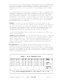
CONNECT SYSTEMS INC.
1802 Eastman Ave. Suite 116
Ventura, Ca. 93003
Phone (805) 642-7184
Fax
(805) 642-7271
Model TP-154
Shared Repeater Tone Panel
USER'S INSTRUCTION MANUAL
S/W rev. 3.01
Manual upgraded January 1997
Made in U.S.A.
Copyright (C) 1997
By
Connect Systems Inc.
IMPORTANT NOTICE
Your TP-154 is equipped with CTCSS Trak... ,
a revolutionary software decoding algorithm that gives the TP-154
unbeatable tone sensitivity and talk down resistance.
This TP-154 is supplied with the ability to decode either the
standard 38 EIA CTCSS or 50 CTCSS tones tones and 104 DCS codes.
To select the number of tones, use JP-7. With JP-7 installed, you
decode 38 tones. With JP-7 removed, you decode 50 tones.
Consider carefully before you jump into the 50 tone version.
Dividing up the subtone spectrum into 50 slots rather than 38
slots gives each standard tone less operating room. The 38 tone
version makes the TP-154 more tolerant of mobile and portable
radios which have poor CTCSS frequency tolerance. We recommend
only using the 38 tone version because in general you will
experience far better system performance. The TP-154 also supports
104 DCS codes. Please see Table 2 for a listing of standard and
non standard tones and codes.
Our recommendation to avoid problems:
DO NOT USE THE 12 NON STANDARD TONES UNLESS ABSOLUTELY NECESSARY!
---------------------------------------------------------------TABLE OF CONTENTS
The Connections ................................
Adjustments ....................................
Jumper Strap Options ...........................
Programming the TP-154 .........................
Per User Programming ......................
Gang Programming ..........................
Global Programming ........................
Interpretation of CD-2 Display Data ............
Display and Rebooting Info .....................
Special Test Modes .............................
Definition of terms ............................
Circuit Description ............................
Warranty .......................................
3
5
6
7
12
13
13
16
17
18
19
21
22
Table 1 CW ID Character Codes .................. 9
Table 2 User Number vs Tone/Code ............... 10
Table 3 Normal / Inverted DCS Codes ............ 11
Schematic Diagrams ............................. 23
Connect Systems Inc.
-Model TP-154
Page 2
THE CONNECTIONS
Two connections must be made to the receiver and three to the
transmitter. Use shielded wires with the shields at each end
connected to chassis ground. (The rear panel barrier strip
terminals labeled "GND" are chassis ground). We recommend using
spade type crimp-on connectors for ease and reliability. Connect
the center wires as follows:
RX AUDIO:
The audio input terminal should be connected directly
to the receivers discriminator (de-modulator) output.
RX COS:
Connect to a point that has good voltage swing when
the squelch is opened/closed. The best point to
connect is to the collector of the transistor that
controls the busy light (if the receiver has one).
Otherwise, you may connect to the squelch gate
control voltage. Your last choice would be to connect
to output of the noise rectifier.
If the point selected goes more positive (voltage
increases) when a signal is received, strap JP-10
center to the + side. If the point goes to a lower
voltage, strap JP-10 from center to the - side.
When the COS threshold control P4 has been properly
adjusted (see page 5), and JP-10 properly strapped
(see page 6), the front panel RECEIVE LED will
illuminate only when a signal is received. This
condition must be achieved for proper operation of
the interconnect.
NOTE: The squelch control in the receiver must be set
for quiet (squelched) receive. Set the squelch as you
would any squelch, but remember if you set it too
tight receive sensitivity may suffer.
TX AUDIO:
Connect to the transmitter audio input or Mic high
line.
PTT:
Connect to the transmitter PTT line.
SUBTONE
The SUBTONE output is used to inject DCS and CTCSS
into the transmitter. The injection point must be
after the IDC clipper circuit, and preferably
directly to the modulator.
NOTE: For CTCSS operation you may use either a phase
modulated or true FM (frequency modulation)
transmitter. However for DCS operation only a true FM
transmitter may be used.
Connect Systems Inc.
-Model TP-154
Page 3
VALID:
This is an open collector NPN transistor output that
is used to let a companion Model 8200 Full Duplex
Interconnect know when DCS or CTCSS is valid. The
transistor is normally on, but is turned off during
the interval that a DCS or CTCSS code is valid. This
output is only used when using the TP-154 in
conjunction with a CSI Model 8200.
+12 VDC:
Connect to a source of 12-14 VDC. The TP-154 is
reverse polarity protected, so a polarity mistake
will not damage your TP-154. Connect the return lead
(-) to GND.
####################
WARNING
####################
The TP-154 contains a power supply sensing circuit that
continuously monitors the input supply voltage. An instantaneous
drop below 10 VDC will cause a microcomputer reset. If the power
supply has poor regulation, erratic operation may result.
The purpose of the input voltage sensor is to protect the nonvolatile EE memory during power up and power down.
If erratic operation is observed be suspicious of poor regulation
from the power supply.
#########################################################
IMPORTANT NOTE
The TP-154 is factory programmed with all 154 tones/codes turned
on. As far as programming is concerned the panel is ready to
operate as soon as it is connected to the receiver and transmitter
and appropriate level adjustments have been made.
Do not attempt any reprogramming until you have the TP-154 up and
running as a repeater. Or you run the risk of a programming error
causing a problem you do not understand. The TP-154 can be
returned to full factory default programming at any time by simply
installing jumper JP-6 and turning the power off and back on
again. You will see || || || || in the display during the reinitializing process. When the display shows ---- the process is
complete. Remove JP-6 and your TP-154 is ready to use programmed
to factory default values.
Should you forget your programming mode access code you will have
to return all programming to the factory default values so that
you can start over again.
Connect Systems Inc.
-Model TP-154
Page 4
ADJUSTMENTS
P1
PREAMP:
The PREAMP control is used to match the audio
level from your receiver to the TP-154. To adjust,
a signal containing 100 HZ CTCSS with about 600 HZ
deviation must be applied to the receiver. Adjust
the PREAMP control until a level of 3V P-P is
observed at TP-1 using an oscilloscope. If an
oscilloscope is not available TP-1 should read 1V
RMS using a VOM.
This completes the adjustment of the PREAMP
control. Future adjustment should only be required
if the TP-154 is connected to a different
receiver.
P2
ID LEVEL:
Courtesy beeps & CW ID level: Adjust for desired
modulation level of the courtesy beep and CW ID.
P3
RPT AUDIO: The REPEAT AUDIO control sets the level of the
voice audio. Set so that 3 khz. input deviation
causes 3 khz. output deviation. This will cause a
linear input/output relationship.
NOTE: The RPT AUDIO control should only be
adjusted after the PREAMP control has been
properly adjusted.
P4
COS:
The COS control sets the COS input threshold
level. Measure the voltage at TP-2 with no signal.
Then measure the voltage again with a signal
applied. Adjust the COS control until the voltage
reading at TP-3 is approximately midway between
the two readings previously obtained at TP-2.
For example: If TP-2 read 2 volts with no signal,
and 4 volts with a signal applied to the receiver,
TP-3 would be set to read 3 volts.
IMPORTANT: If the COS polarity select strap JP-10
is set correct and the COS control is properly
adjusted the RECEIVE LED will illuminate when
there's a signal, and will go out when the signal
is removed.
P5
DCS:
The DCS control sets the modulation level of
digital DCS.
P6
CTCSS:
The CTCSS control sets the modulation level of
analog CTCSS.
P7
DTMF:
The DTMF control adjusts the deviation of
theoutgoing DTMF transpond and regenerated
DTMF.Set for about 2.5 KHz. deviation.
Connect Systems Inc.
-Model TP-154
Page 5
JUMPER STRAP OPTIONS
JP-1
De-emphasis strap. If you have connected to the
discriminator output, JP-1 should be installed. If you have
connected to a source of flat (already de-emphasized) audio
such as the high end of the volume control JP-1 must be
removed. If JP-1 is improperly strapped the audio will not
sound proper and DTMF will not decode properly.
JP-2
Output level strap. The audio output is selectable in two
ranges. With the strap installed, the audio out is 0-1 volt.
With the strap removed, the output range is 0-5 volts. The
strap should be installed in most installations.
JP-3
DCS/CTCSS Level strap. The DCS/CTCSS output level is
selectable in two ranges. With the strap installed, the
level is 0-1 volt. With the strap removed, the output range
is 0-5 volts. The strap should be installed in most
installations.
JP-4
PTT Polarity. This strap gives you a choice of pull to
ground, or pull to +12 VDC for transmitter keying.
JP-5
LED Power. Removal disables all front panel LEDS (except
PTT) and is used to save power in low power applications
such as solar powered installations.
JP-6
Reset Factory Settings. If you wish to return the
programming back to factory settings simply install this
strap and turn the power on. When the initialization begins,
the display will show "11 11 11 11". When the procedure is
complete, the display will show "----". At this point remove
the jumper. The display will blank and the TP-154 is ready
to use just like it came from the factory.
JP-7
50 or 38 tones. Install this jumper to operate in 38 tone
mode. Remove this jumper to operate in 50 tone mode. see
the IMPORTANT NOTICE at the beginning of the manual for
more information.
JP-8
JP-9
8200 compatible. Install this strap only if the TP-154 is
going to operate in conjunction with a CSI Model 8200 Full
Duplex Interconnect. Installation modifies TP-154 operation
for compatibility.
Not Used. There is no JP-9
JP-10 COS Polarity Select. This strap must be installed. Select
the polarity that causes the REC led to illuminate when a
signal is received, and go out when there's no signal. Note
that the COS threshold adjustment P4 must first be adjusted.
Connect Systems Inc.
-Model TP-154
Page 6
PROGRAMMING THE TP-154
The TP-154 can be programmed with DTMF from a radio or service
monitor, or by plugging any DTMF telephone set into the rear panel
RJ-11 modular jack and using the telephone DTMF keypad.
There are three programming modes:
1. PER USER PROGRAMMING: This allows you to make programming
selections on a per user basis. See TABLE 2 for User Number vs
Tone/Code
2. GANG PROGRAMMING: This allows you to quickly program all 154
user slots to the same setting. For example you could enable or
disable the courtesy tone for all users with a single command.
Use the gang programming feature to quickly set all users to
the condition you wish for the majority and then afterward use
the Per User Programming to modify individual users as
required. For Example: If you only want five users enabled, you
would disable all users with gang programming and then
selectively enable the five desired users with per user
programming.
3. GLOBAL PROGRAMMING: This allows you to program selections that
affect all users at once. For example, DCS polarity or Hog
Penalty time etc. (Global Programmed items are not individually
programmable on a per user basis).
To Enter and Exit Programming Mode: To enter programming mode you
must first enter the programming mode access code. The access code
consists of six digits plus a leading * and a trailing #. The
syntax is *mmmmmm#. The factory default programming access code is
123456 (note that this code is always six digits in length).
Therefore the code required to get into programming mode is
*123456#. This code will be valid unless you change the
Programming Mode Access Code in the GLOBAL programming area.
When programming is completed send #### to exit the programming
mode. (If you forget, the TP-154 is designed to self exit three
minutes after the last DTMF command).
Remote and Local Programming Modes: When the TP-154 receives the
program mode access code it checks to see if the code came from a
radio or from a local telephone keypad. If the code is received
from the radio the TP-154 goes into Remote Programming mode. If
the code does not come from the radio the TP-154 knows that you
are local and using a DTMF telephone as a keypad.
In Remote Programming mode the transmitter remains keyed and a
beep will be heard about every five seconds to remind you that the
TP-154 is still in Program Mode. The front panel PROGRAM LED will
flash on and off. A DTMF sequence is transponded back after each
command sequence for programming validation on your CD-2 Decoder
Unit.
Connect Systems Inc.
-Model TP-154
Page 7
In Local Programming Mode the front panel PROGRAM LED is steady on
(non-flashing) and the transmitter remains off. Each time you make
a programming entry the results are displayed on the front panel
display (rather than a DTMF transpond) for validation.
Command Syntax: When programming, you will enter programming
sequences such as *nnn#09#mm#. (This particular command programs a
users first character of CW ID). Or, *nnn#01#J#. (This command
enables or disables a users courtesy beep).
In each case nnn defines the user number (001-154). See TABLE 2 to
determine user Number vs Tone/Code, mm is a choice which you may
supply and J is always 1 for enable or 0 for disable.
De-limiters (separators) are used to segregate data fields. Every
command you program begins with * and then the delimiters that
follow are the # symbol.
Leading zeros: Data fields such as nnn, mm, mmmmmm etc. require
that you enter the number of digits specified. Numbers which have
fewer digits than the field calls for will require leading zeros.
Example: An nnn (User Number) field requires three digits. You
would enter user number 6 as 006 or user number 84 as 084.
Local Display: The front panel display is active during local or
remote programming. The * and # delimiters are displayed as - and
|| because the display cannot show the * and #. Each time you
enter a delimiter the previous information is blanked and the
delimiter plus data that follows is displayed. For example: The
command *013#09#20# would appear as: -013, ||09, ||20.
Remote Data Downloading: The TP-154 will transpond a DTMF
validation code each time you send a programming command from your
radio and each time you send a specific request for data. These
codes will appear on your CD-2 Communications Decoder Unit exactly
as they appear on the TP-154 front panel display and give you
positive feedback about data entry and how your TP-154 is
programmed. The command syntax for data feedback is shown in the
programming lists. Also see "Interpretation of CD-2 Display Data
on page 15. The left two digits give you the parameter number and
the right two digits show the programmed data.
WE HIGHLY RECOMMEND THAT YOU PURCHASE A COMPANION CD-2 AS A
PROGRAMMING AID FOR YOUR TP-154'S!!
Understanding the programming format: Following is a typical line
excerpted from the GLOBAL PROGRAMMING COMMANDS:
----------------------------------------------------------------TO PROGRAM
TO
DISPLAY
STUCK MIKE ACTIVITY TIMER
*000#22#mm#
*000#22*
mm 01-99 0 to disable (10-990 Secs - 10 sec/step) [mm=3=30 Secs]
-----------------------------------------------------------------
Connect Systems Inc.
-Model TP-154
Page 8
The top bold line identifies the item you may wish to program and
the syntax to use for programming followed by the syntax to use to
read this parameter back to either the front panel display if
programming locally or to your CD-2 if programming from a remote
site.
The subline tells you everything you need to know to program this
particular parameter. The first information lets you know the
allowable range for mm and that if you can enter zero to disable
this parameter altogether. In parenthesis the actual range of
adjustment is indicated. If you multiply the value you enter (mm)
by the step size you will have the resultant time. The information
in brackets [mm = 3 = 30 Secs] is how the TP-154 is programmed
when shipped from the factory.
Example: You wish to set the Stuck Mic. Activity Timer to 60
seconds for all users on the system. First determine the value for
mm. This would be 6 (6 times the step value of 10 seconds equals
60 seconds. The desired value). To make this modification, enter
the following sequence on your local or remote DTMF keypad:
*000#22#06#. (Note the leading zero which must be used)
To read this parameter back on the local display or on your CD-2
simply send: *000#22*.
Resetting your position: If you are distracted or have a lapse and
forget where you are in the middle of a command sequence simply
send * three times (***) and start the command sequence over
again. Example: You have just entered *000#22#0 and suddenly you
forget where you are. Simply send *** and begin inputting the
command over again.
Be organized. We recommend thinking through what you want to
program and then writing down the entire sequence of codes you
must send including programming mode access code at the beginning
and exit code (####) at the end. You may send a request to display
any data you wish to see on the local display or CD-2 at any time
while in programming mode.
_______________________________________________________________
|
|
|
TABLE 1 CW ID CHARACTER CODES
|
|_______________________________________________________________|
| A = 0 | G = 6 | M = 12 | S = 18 | Y = 24 | 5 = 30 | WORD
|
| B = 1 | H = 7 | N = 13 | T = 19 | Z = 25 | 6 = 31 | SPACE= 36|
| C = 2 | I = 8 | O = 14 | U = 20 | 1 = 26 | 7 = 32 |
|
| D = 3 | J = 9 | P = 15 | V = 21 | 2 = 27 | 8 = 33 | SLANT
|
| E = 4 | K = 10 | Q = 16 | W = 22 | 3 = 28 | 9 = 34 | BAR = 37 |
| F = 5 | L = 11 | R = 17 | X = 23 | 4 = 29 | 0 = 35 |
|
|
|
|
|
|
|
| MESSAGE |
|
|
|
|
|
|
| END = 38 |
|_______|________|________|________|________|________|__________|
|
|
|
e.g. CW ID message desired is 'CSI' Enter 2, 18, 8, 38
|
|_______________________________________________________________|
Connect Systems Inc.
-Model TP-154
Page 9
USER
001
002
003
004
005
006
007
008
009
010
011
012
013
014
015
016
017
018
019
020
021
022
023
024
025
026
027
028
029
030
031
032
033
034
035
036
037
038
039
CODE
67.0
69.4
71.9
74.4
77.0
79.7
82.5
85.4
88.5
91.5
94.8
97.4
100.0
103.5
107.2
110.9
114.8
118.8
123.0
127.3
131.8
136.5
141.3
146.2
151.4
156.7
159.8
162.2
165.5
167.9
171.3
173.8
177.3
179.9
183.5
186.2
189.9
192.8
196.6
USER CODE
*
*
*
*
*
*
*
*
040
041
042
043
044
045
046
047
048
049
050
051
052
053
054
055
056
057
058
059
060
061
062
063
064
065
066
067
068
069
070
071
072
073
074
075
076
077
078
199.5
203.5
206.5
210.7
218.1
225.7
229.1
233.6
241.8
250.3
254.1
023
025
026
031
032
036
043
047
051
053
054
065
071
072
073
074
114
115
116
122
125
131
132
134
143
145
152
155
*
*
*
*
USER CODE
USER CODE
079
080
081
082
083
084
085
086
087
088
089
090
091
092
093
094
095
096
097
098
099
100
101
102
103
104
105
106
107
108
109
110
111
112
113
114
115
116
117
118
119
120
121
122
123
124
125
126
127
128
129
130
131
132
133
134
135
136
137
138
139
140
141
142
143
144
145
146
147
148
149
150
151
152
153
154
156
162
165
172
174
205
212
223
225
226
243
244
245
246
251
252
255
261
263
265
266
271
274
306
311
315
325
331
332
343
346
351
356
364
365
371
411
412
413
423
431
432
445
446
452
454
455
462
464
465
466
503
506
516
523
526
532
546
565
606
612
624
627
631
632
654
662
664
703
712
723
731
732
734
743
754
TABLE 2
User Number vs Tone/Code
Users 001-050 are CTCSS.
051-154 are DCS.
NOTE: The twelve tones with an * are non standard and are
available when JP-7 is removed. When JP-7 is installed, they are
not available. See page 2 and page 6 for details.
Connect Systems Inc.
-Model TP-154
Page 10
Normal Invert
-------------023
047
025
244
026
464
031
627
032
051
036
172
043
445
047
023
051
032
053
452
054
413
065
271
071
306
072
245
073
506
074
174
114
712
115
152
116
754
122
225
125
365
131
364
132
546
134
223
143
412
145
274
152
115
155
731
156
265
162
503
165
251
172
036
174
074
205
263
212
356
Normal Invert
-------------223
134
225
122
226
411
243
351
244
025
245
072
246
523
251
165
252
462
255
446
261
732
263
205
265
156
266
454
271
065
274
145
306
071
311
664
315
423
325
526
331
465
332
455
343
532
346
612
351
243
356
212
364
131
365
125
371
734
411
226
412
143
413
054
423
315
431
723
432
516
Normal Invert
-------------445
043
446
255
452
053
454
266
455
332
462
252
464
026
465
331
466
662
503
162
506
073
516
432
523
246
526
325
532
343
546
132
565
703
606
631
612
346
624
632
627
031
631
606
632
624
654
743
662
466
664
311
703
565
712
114
723
431
731
155
732
261
734
371
743
654
754
116
TABLE 3
Normal / Inverted DCS Codes
It is important to have the DCS decode and DCS encode polarities
programmed correctly. The default values are set to normal for
incoming and outgoing DCS. The radios you use may need to have
incoming and/or outgoing DCS set for inverted polarity.
Example: An incoming 023 code reads as 047. Inverting the DCS
Polarity Decode parameter will correct the code. An outgoing code
of 212 appears as 356 on your service monitor or CD-2. Simply
invert the DCS Encode Polarity to correct.
DCS Polarity Decode and Encode parameters are found in the Global
Programming section.
Connect Systems Inc.
-Model TP-154
Page 11
PER USER PROGRAMMING COMMANDS
----------------------------(Programs one user at a time)
TO PROGRAM
|
V
TO DISPLAY
|
V
LIST ALL PER USER PROGRAMMING ON DISPLAY OR CD-2
*nnn#00*
Downloads entire user file to CD-2 or front panel display.
COURTESY BEEP
J = 1 = Enabled,
J = 0 = Disabled
*nnn#01#J#
*nnn#01*
[J = 1 = Enabled]
CTCSS/DCS DURING HANG TIME
*nnn#02#J#
*nnn#02*
J = 1 = Enabled, J = 0 = Disabled
[J = 1 = Enabled]
BARGE IN CONTROL
*nnn#03#J#
*nnn#03*
J = 1 = Enabled, J = 0 = Disabled
[J = 1 = Enabled]
If enabled, the subscriber you are currently programming can be
barged in on by subscribers with a different tone/code. If
disabled, the subscriber you are currently programming can not
be barged in on by subscribers with a different tone/code until
hangtime expires.
SUBSCRIBER ENABLE/DISABLE
*nnn#04#J#
*nnn#04*
J = 1 = Enabled, J = 0 = Disabled
[J = 1 = Enabled]
Allows enabling or disabling specific tones or codes.
RESERVE TONE
*nnn#05#J#
*nnn#05*
J = 1 = Enabled, J = 0 = Disabled
[J = 0 = Disabled]
If a subscriber tone/code is turned off and reserve tone is
enabled, the repeater will come up, but no audio will pass.
Beeps indicate reserve tone is active.
HOG PENALTY
*nnn#06#J#
*nnn#06*
J = 1 = Enabled, J = 0 = Disabled
[J = 0 = Disabled]
See DEFINITION OF TERMS for information about Hog Penalties.
SUBSCRIBER HANG TIME
*nnn#07#mm#
*nnn#07*
mm 10-99 (1.0-9.9 Sec's - .1 sec/step)
[mm = 30 = 3 Sec's]
CROSS TONE
*nnn#08#mmm#
*nnn#08*
Can cross any DCS/CTCSS code nnn to any DCS/CTCSS code mmm
See Table 2.
[nnn=mmm]
CWID
CWID
CWID
CWID
CWID
CWID
CWID
CWID
CWID
CWID
SEQUENCE
SEQUENCE
SEQUENCE
SEQUENCE
SEQUENCE
SEQUENCE
SEQUENCE
SEQUENCE
SEQUENCE
SEQUENCE
CHARACTER
CHARACTER
CHARACTER
CHARACTER
CHARACTER
CHARACTER
CHARACTER
CHARACTER
CHARACTER
CHARACTER
See Table 1.
Connect Systems Inc.
1
2
3
4
5
6
7
8
9
10
*nnn#09#mm#
*nnn#10#mm#
*nnn#11#mm#
*nnn#12#mm#
*nnn#13#mm#
*nnn#14#mm#
*nnn#15#mm#
*nnn#16#mm#
*nnn#17#mm#
*nnn#18#mm#
*nnn#09*
*nnn#10*
*nnn#11*
*nnn#12*
*nnn#13*
*nnn#14*
*nnn#15*
*nnn#16*
*nnn#17*
*nnn#18*
[CHAR 1 - CHAR 10 are defaulted to 38]
-Model TP-154
Page 12
CW ID characters and corresponding mm values may be obtained
from
Table 1. The entry immediately following your message
must be 38 which means "end of message".
Example: To program KYZ 2584 the following mm sequence is
required in character positions 1-8: 10 24 25 27 30 33 29 38
----------------------------------------------------------------GANG PROGRAMMING
---------------(Programs all 154
user slots at once)
COURTESY TONE
CTCSS DURING HANG TIME
BARGE IN CONTROL
USER ENABLE/DISABLE
RESERVE TONE
HOG PENALTY ENABLE
TO PROGRAM
|
V
*999#01#J#
*999#02#J#
*999#03#J#
*999#04#J#
*999#05#J#
*999#06#J#
-------------------------------------| In position J for all of the above |
| enter 1 for enable, 0 for disable. |
-------------------------------------SUBSCRIBERS HANG TIME
*999#07#mm#
mm 5-99 (.5-9.9 Seconds - .1 sec/step)
[mm = 30 = 3 Sec's]
Note: There are no display codes for Global programming because
the programming affects 154 locations. You must view
subscriber programming on an individual basis.
----------------------------------------------------------------GLOBAL PROGRAMMING COMMANDS
--------------------------(These parameters affect all users)
TO PROGRAM
|
V
TO DISPLAY
|
V
LIST ALL GLOBALS ON DISPLAY OR CD-2
*000#00*
Downloads all global parameters to CD-2 or front panel display.
ANTI-KERCHUNKING TIME
*000#19#mm#
*000#19*
mm = 01-99, 0 to disable
(.1 sec/step)
[mm = 0 = Disable]
If enabled, repeater will not hang unless user keys down at
least as long as the time set. Does not affect pick up speed.
Connect Systems Inc.
-Model TP-154
Page 13
SQUELCH TAIL LENGTH
*000#20#mm#
*000#20*
mm 00-99
(0-99 Ms - 1 Ms/step)
[mm = 0 = 0 Milliseconds]
Set to 0 for minimum tail. Only used if the receiver has a poor
squelch and can stop word clipping by adding squelch delay. If
there is a tail noise when set to 0, it is caused by slow
squelch response in the receiver. The TP-154 does not add any
more tail than is inherent to the receivers squelch if set to 0.
CTCSS/DCS HOLD DELAY
*000#21#mm#
*000#21*
mm 3-99 (.3-9.9 Sec's - .1 sec/step)
[mm = 30 = 3 Sec's]
Use the lowest setting possible without introducing talk off.
Fills the missing gap when CTCSS/DCS decoding momentarily
falters due to overmodulation, momentary weak signal etc.
STUCK MIKE ACTIVITY TIMER
*000#22#mm#
*000#22*
mm 01-99, 0=disable (10 sec/step)
[mm = 18 = 180 Sec's]
DCS ENCODE POLARITY
*000#23#J#
*000#23*
0 = NORMAL, 1 = Inverted
[mm = 0 = Normal]
Corrects transmitted DCS Polarity.
DCS DECODE POLARTIY
0 = NORMAL, 1 = Inverted
Corrects received DCS polarity.
*000#24#J#
*000#24*
[mm = 0 = Normal]
HOG PENALTY TIME
*000#25#mm#
*000#25*
mm 06-99 (60-990 Sec's - 10 sec/step)
[mm = 18 = 180 Sec's]
HOG IDLE TIMER
*000#26#mm#
*000#26*
mm 02-99 (20-990 Sec's - 10 sec/step)
[mm = 06 = 60 Sec's]
HOG TIMER
*000#27#mm#
*000#27*
mm 06-99 (60-990 Sec's - 10 sec/step)
[mm = 18 = 180 Sec's]
See DEFINITION OF TERMS for information about Hog Penalties.
COR OR DCS/CTCSS OPERATE
*000#28#J#
*000#28*
J = 0 = DCS/CTCSS, 1 = COR
[J = 0 = DCS/CTCSS]
NOTE: The operating parameters for carrier operation are
programmed in the user No. 001 file.
RESPONSE DELAY TO CD-2
*000#29#mm#
*000#29*
mm 00-99
(0-9.9 Sec's - .1 sec/step)
[mm = 10 = 1 Sec.]
Delays CD-2 data transpond to give your base time to return to
receive after entering a command.
PROGRAMMING MODE ACCESS CODE
*000#30#mmmmmm#
*000#30*
(Code must be precisely six digits)
[mmmmmm = 123456]
This code must be used to enter programming mode locally or over
the air.
Connect Systems Inc.
-Model TP-154
Page 14
COURTESY TONE DELAY
*000#31#mm#
*000#31*
mm 01-99 (.01-.99 Sec's - 10 Ms/step)
[mm = 10 = 100 Ms]
Delays courtesy beep after mobile drops his carrier.
SYSTEM CW ID INTERVAL
*000#32#mm#
*000#32*
mm 01-99, 0 to disable (1-99 Min's - 1 Min/step) [mm=0=Disable]
Determines how often the system will send its callsign when the
system is not in use.
USER CW ID INTERVAL
*000#33#mm#
*000#33*
mm 01-99 0=disable (10-990 Sec's - 10 Sec/step) [mm=0=Disable]
A subscribers callsign is sent five seconds after picking up the
system and then every "CW ID Interval" thereafter. If hangtime
is allowed to drop, CW ID timing starts over five seconds after
picking up the system again.
CW ID SPEED
*000#34#mm#
mm 04-10 (Increase mm for slower code speed)
CWID
CWID
CWID
CWID
CWID
CWID
CWID
CWID
CWID
CWID
SEQUENCE
SEQUENCE
SEQUENCE
SEQUENCE
SEQUENCE
SEQUENCE
SEQUENCE
SEQUENCE
SEQUENCE
SEQUENCE
CHARACTER
CHARACTER
CHARACTER
CHARACTER
CHARACTER
CHARACTER
CHARACTER
CHARACTER
CHARACTER
CHARACTER
See Table 1.
1
2
3
4
5
6
7
8
9
10
*000#35#mm#
*000#36#mm#
*000#37#mm#
*000#38#mm#
*000#39#mm#
*000#40#mm#
*000#41#mm#
*000#42#mm#
*000#43#mm#
*000#44#mm#
*000#34*
[mm=05=20 WPM]
*000#35*
*000#36*
*000#37*
*000#38*
*000#39*
*000#40*
*000#41*
*000#42*
*000#43*
*000#44*
[CHAR 1 - CHAR 10 are defaulted to 38]
CW ID characters and corresponding mm values may be obtained
from
Table 1. The entry immediately following your message
must be 38 which means "end of message". Example: To program KYZ
2584 the following mm sequence is required 10 24 25 27 30 33 29
38
CARRIER DROP DELAY
mm = 00-99, (0 - .99 Sec's
*000#45#mm#
*000#45*
10 Ms./step) [mm = 99 = .99 Sec's]
Adjusts how long carrier remains on after CTCSS/DCS drops at end
of hangtime. Keeping the carrier on quiets the mobile while the
mobile CTCSS/DCS decoder is dropping and allows the repeater to
go off without a squelch tail heard. The default value is .99
seconds and probably will not need to be changed.
Note: The carrier drop delay is additive to hangtime and in
effect increases the total beyond the value set for hangtime.
Connect Systems Inc.
-Model TP-154
Page 15
INTERPRETATION OF CD-2 DISPLAY DATA
When the *nnn#00* command is sent from the remote programming
location, the TP-154 responds with a lengthy string of DTMF data
to load the CD-2 memory with all data relative to user nnn. Upon
completion of the string the CD-2 begins displaying all of the
user programming for the user (nnn) which has been requested. The
left two digits identify which data is displayed and the right two
digits show the actual data. If the data exceeds two digit
positions as in line 7 below, the data is shown on the next line.
PER USER DATA ON CD-2:
(Command syntax = *nnn#00*)
-NNN USER NUMBER
01-J COURTESY TONE
02-J CTCSS/DCS DURING HANG
03-J BARGE IN CONTROL
04-J DEADBEAT CONTROL
05-J RESERVE TONE
06-J HOG PENALTY
07MM USER HANG TIME
08-- CROSS TONE
NNN- CROSS TONE
09MM CWID CHARACTER 1
10MM CWID CHARACTER 2
11MM CWID CHARACTER 3
12MM CWID CHARACTER 4
13MM CWID CHARACTER 5
14MM CWID CHARACTER 6
15MM CWID CHARACTER 7
16MM CWID CHARACTER 8
17MM CWID CHARACTER 9
18MM CWID CHARACTER 10
---- END OF SEQUENCE
GLOBAL DATA ON CD-2:
19MM
20MM
21MM
22MM
23-J
24-J
25MM
26MM
27MM
28-J
29MM
30MM
NNNN
31MM
32MM
33MM
001 -154
0 - 1
0 - 1
0 - 1
0 - 1
0 - 1
0 - 1
05 - 99
001 - 154
00 - 38
00 - 38
00 - 38
00 - 38
00 - 38
00 - 38
00 - 38
00 - 38
00 - 38
00 - 38
(Command syntax = *000#00*)
ANTI KERCHUNKING TIME
SQUELCH TAIL LENGTH
CTCSS/DCS HOLD DELAY
STUCK MIKE TIMER
DCS POLARITY ENCODE
DCS POLARITY DECODE
HOG PENALTY TIME
HOG IDLE TIME
HOG MONITOR
DCS/COR OPERATED
RESPONSE DELAY TO CD-2
PROGRAM ACCESS CODE
PROGRAM ACCESS CODE
COURTESY TONE DELAY
SYSTEM CW INTERVAL
USER CW INTERVAL
Connect Systems Inc.
VALUE
VALUE
VALUE
VALUE
VALUE
VALUE
VALUE
VALUE
N/A
VALUE
VALUE
VALUE
VALUE
VALUE
VALUE
VALUE
VALUE
VALUE
VALUE
VALUE
N/A
-Model TP-154
VALUE
VALUE
VALUE
VALUE
VALUE
VALUE
VALUE
VALUE
VALUE
VALUE
VALUE
VALUE
VALUE
VALUE
VALUE
VALUE
00 - 99
00 - 99
00 - 99
00 - 99
0 - 1
0 - 1
00 - 99
00 - 99
00 - 99
0 - 1
00 - 99
00 - 99
0000 - 9999
00 - 99
00 - 99
00 - 99
Page 16
34MM
35MM
36MM
37MM
38MM
39MM
40MM
41MM
42MM
43MM
44MM
----
MORSE SPEED
CWID CHARACTER 1
CWID CHARACTER 2
CWID CHARACTER 3
CWID CHARACTER 4
CWID CHARACTER 5
CWID CHARACTER 6
CWID CHARACTER 7
CWID CHARACTER 8
CWID CHARACTER 9
CWID CHARACTER 10
END OF SEQUENCE
VALUE
VALUE
VALUE
VALUE
VALUE
VALUE
VALUE
VALUE
VALUE
VALUE
VALUE
N/A
00
00
00
00
00
00
00
00
00
00
00
-
99
38
38
38
38
38
38
38
38
38
38
-----------------------------------------------------------------
DISPLAY AND REMOTE BOOTING INFORMATION
DTMF DISPLAY: The display will indicate all DTMF codes that are
received on the repeater input when in operate mode. However The
digital displays used in the TP-154 are not capable of directly
displaying the *, #, A, B, C or D. The * and # are displayed using
- and ||. A, B, C and D are displayed using the numbers 1. 2. 3.
and 4. Note that these are distinguishable from 1 2 3 and 4
because the decimal points accompany the digits. The Table below
shows all the DTMF digits and how they appear on the front panel
display:
1
2
3
4
=
=
=
=
1
2
3
4
5
6
7
8
=
=
=
=
5
6
7
8
9
0
*
#
=
=
=
=
9
0
||
A
B
C
D
=
=
=
=
1.
2.
3.
4.
RE-BOOTING: A variety of conditions can occur (e.g. lightning)
that will occasionally lock up a microprocessor. The only solution
is to restart the processor. In a Personal Computer you may be
familiar with the term "warm boot" (this is done using the Cont +
alt + Del keys) or "hard boot" which is accomplished by either
pressing the reset button or by turning the power off and back on
again.
Your TP-154 has been provided with the ability to do both warm
boot and hard boot remotely using DTMF. If a malfunction occurs
first try a warm boot. This is accomplished by pressing the # five
times (#####). This will normally restart the processor and
correct the difficulty. If a warm boot does not restore operation
try a hard boot (full reset) by pressing any DTMF digit for ten or
more seconds. (Re-booting will have no effect on user
programming).
Connect Systems Inc.
-Model TP-154
Page 17
SPECIAL TEST MODES
1. Test Transmission with any DCS or CTCSS: Occasionally it may be
handy to have the repeater send a carrier with any DCS code or
CTCSS tone you wish for various test purposes. First enter the
program mode as previously discussed. Then enter this sequence:
*nnn#99#
Where nnn is the user number that corresponds to the tone or
code you want the TP-154 to transmit. See Table 2. The test
transmission will last as long as you remain in program mode or
until you enter a * or a new command. Don't forget that the TP154 will automatically exit program mode three minutes after
the last command. You can occasionally hit any digit except *
or # to extend the test mode time if desired. Enter #### when
you wish to exit program mode.
2. DCS/CTCSS display: While at the site you may wish to have the
front panel display indicate the DCS and CTCSS codes of all
signals heard on the repeater input. Simply enter the following
code while in operate mode:
*nnnnnn*
Where nnnnnn is the same user programmable code sequence used
to enter the programming mode. The difference is that the
program mode access code ends with # while the display mode
sequence ends with *. If the factory programmed access code has
not been changed simply enter *123456* to activate the
DCS/CTCSS display mode.
The display mode is disabled in any of the following ways:
1. By entering #### from your DTMF keypad.
2. By entering programming mode.
3. A built in software timer will automatically turn off the
display mode 30 minutes after it has been enabled.
Note: The TP-154 does not normally display DCS or CTCSS in
operate mode to realize a significant reduction in average
power consumption which is important in solar powered
installations. In some applications a slight buzz in the repeat
audio may be noticeable while in display mode. However this
will go away as soon as display mode is disabled.
3.
Display all CTCSS/DCS codes enabled for repeater usage: To
view a list of all CTCSS/DCS codes enabled for repeater use
simply enter the following sequence while in program mode..
*888#
Connect Systems Inc.
-Model TP-154
Page 18
DEFINITION OF TERMS
Courtesy beep: A brief tone at the end of a users transmission
that lets the party you are speaking with know that it is their
turn to reply.
Barge in: An attempt to cut in by a user who does not have the
DCS/CTCSS code of the user currently using the system.
Reserve tone: A tone in reserve tone status will bring up the
repeater but audio will not pass.
Cross tone: Converts a users input DCS or CTCSS to another DCS or
CTCSS as desired.
CW ID: Automatic identification of call sign in Morse Code.
Hangtime: The amount of time the repeater transmitter remains on
the air after a user stops transmitting.
Kerchunking: A kerchunker is a user that briefly hits his PTT
switch to see if he can raise the repeater. Many find this
practice annoying. The Anti-Kerchunking feature in the TP-154 is
designed to stop users who like to kerchunk. The Anti-Kerchunking
filter does not affect pick-up time or repeat capability, however
if a transmission is shorter than the Anti-Kerchunk time there
will be no hangtime when the user unkeys.
CTCSS/DCS hold delay: A software timer that fills in momentary DCS
or CTCSS loss when a signal is weak. When the hold delay is set to
at least two seconds the effective receiver sensitivity is
precisely the same as the receivers' squelch sensitivity.
Stuck Mic. activity timer: Sets the maximum continuous
(uninterrupted) talk time. If a user talks past the activity timer
time, the repeater merely stops transmitting until the input drops
and is picked up anew.
DCS polarity: Characteristics of receivers and transmitters can
invert DCS. The TP-154 has independently programmable receive and
transmit invert to accommodate your radios.
Response delay to CD-2: The amount of time from a download request
until the TP-154 begins outputting a DTMF download to your CD-2
Communications Decoder Unit. This time is required if you are
programming from a half duplex radio.
User Enable/Disable: Ability to turn a subscriber off for non
payment and back on in response to payment. Sometimes it may be
desirable to put a subscriber into reserve tone status rather than
use the deadbeat disable. That way he will realize that he is
picking up the repeater but can't talk. This may give the user a
clue that they need to write a check.
Connect Systems Inc.
-Model TP-154
Page 19
Hog: A user or user group that monopolizes airtime.
Hog Penalty: This feature is designed to give the system manager
some control over airtime hogs which may drive other customers
away.
In order to use the Hog Penalty feature it is necessary to
understand how it works. There are three timers which can be
individually set in the global programming. These are ...
HOG MONITOR: This timer sets the maximum talk time a subscriber
may use without incurring a no talk penalty. Warning beeps during
the final thirty seconds indicate that a penalty is forthcoming if
use is not quickly terminated. If the subscriber ignores the
warning beeps for the full thirty seconds he is penalized by not
being able to use the system for the "penalty time" duration.
IDLE TIMER: The "hog monitor" timer is reset if the user does not
use the system for the "idle time" this gives the
user a clean slate. It must be noted that the "hog
monitor" timer time is cumulative, if the idle time
criteria is not met.
PENALTY TIME: If the subscriber exceeds the cumulative "hog
monitor" timer time he receives a hog penalty time.
The TP-154 can only track the most recent five users for hog
penalty. If the system operator (or any other user) enters "###",
all hog timers will be cleared, allowing the penalized Hog(s) to
use the system before the penalty time has expired
Connect Systems Inc.
-Model TP-154
Page 20
CIRCUIT DESCRIPTION
The incoming audio is buffered, de-emphasized and amplified to the
amount set by the PREAMP control by input op amps U1. The audio
then proceeds to a six pole low pass filter and a six pole high
pass filter. The low pass filter U2 removes voice audio and
extracts the DCS/CTCSS signal for detection at the adaptive
differential comparator. The comparator output is fed to the
microcomputer U12 pin 12 for software DCS/CTCSS detection. The six
pole high pass filter (U3) removes CTCSS and DCS from the incoming
audio to avoid retransmission. The audio from the high pass filter
continues through the squelch switch U18 and on to the audio
output amplifier.
The COS input is buffered and compared to a reference voltage
which is set by the COS threshold pot. The output then proceeds to
the polarity select strap JP-10 and then to the microcomputer U12
pin 6.
DTMF is decoded and regenerated by U11 with some assistance from
the microcomputer U12.
DCS is generated directly by the microcomputer U12. CTCSS is
generated by waveform generator U16. The microcomputer U12
controls the U16 waveform generator via pins 34,35 and 36. DCS and
CTCSS have separate level controls the output of each is fed to
summation amplifier and four pole low pass filter U4. The output
of U4 feeds the transmitter modulator with SUBTONE.
The PTT circuit consists of Q6, Q14 and Q20. This circuit is
controlled by the microcomputer U12 via pin 7. A polarity select
strap gives the choice of ground keying or plus keying.
A power on reset circuit consisting of Q21 and associated
components monitors the input voltage and quickly halts the
microcomputer if the applied input voltage is too low. The power
on reset circuit provides proper computer start up after power is
applied and protects the EE memory U13 on power down.
Counters U22 and U23 divide the 448 KHz
remote re-booting of the microprocessor
digit exceeds 9 seconds in duration. At
U22 pin 15 turns on transistor Q9 which
on reset circuit.
clock from U11 and allow
when any incoming DTMF
the end of nine seconds
in turn enables the power
The front panel digital display U6-U9 are controlled by the
display driver U5. The microcomputer U12 talks to U5 via pins
37,38 and 39.
Incoming power is fed through reverse polarity protect diode D8
and then fuse F1. From there the +V voltage feeds a +5 volt
regulator U20 used by the digital components. Another smaller +5
volt regulator U21 is used to supply bias and reference voltage to
the analog op-amps etc.
Connect Systems Inc.
-Model TP-154
Page 21
LIMITED WARRANTY
Connect Systems Inc. (CSI) hereby warrants our products to be free from
defective workmanship for a period of one year and defective parts for a
period of five years from date of sale to the initial end user. This
warranty applies only to the original consumer/end user purchaser of each
CSI product. During the first year of warranty, CSI will repair any of
its products at no charge providing the defective unit is shipped prepaid
and service is performed by CSI. During the years 2-5, there shall be no
charge for replacement parts providing that the defective unit is shipped
prepaid and service is performed by CSI. Conventional prevailing labor
and shipping charges will apply following the end of the first year. CSI,
at its sole discretion, will replace defective parts on an exchange basis
for the first five years of ownership by the original purchaser. All
shipping cost are the responsibility of the customer.
What is not covered by this limited warranty:
This warranty shall not apply, if, in our judgment the defects are caused
by misuse, lightning strikes, customer modification, water damage,
negligent use, improper installation, overloads caused by external
voltage fluctuations, use of unregulated power supply, damage caused by
transit or handling or an abusive treatment not in accordance with
ordinary product use or the product serial number has bee removed,
altered, or defaced. Specific Exclusion: This warranty specifically
excludes transistors in the PTT (Push to Talk) circuitry (Q6 & Q20).
These components can only fail from external abuse.
THIS WARRANTY IS IN LIEU OF ALL OTHER WARRANTIES, STATEMENTS OR
REPRESENTATIONS, AND UNLESS STATED HEREIN, ALL SUCH WARRANTIES,
STATEMENTS OR REPRESENTATIONS MADE BY ANY OTHER PERSON OR FIRM ARE VOID.
ALL IMPLIED WARRATIES IN CONNECTION WITH THE SALE OF THIS EQUIPMENT,
INCLUDING THE WARRANTY OF MERCHANTABILITY, SHALL BE OF THE SAME DURATION
AS THE WARRANTY PERIOD STATED ABOVE. SOME STATES DO NOT ALLOW LIMITATIONS
OF HOW LONG AN IMPLIED WARRANTY LAST, SO THE ABOVE LIMITATION MAY NOT
APPLY TO YOU. IN THE EVENT OF PRODUCT FAILURE WHICH PROVES TO BE CAUSED
BY A DEFECT IN WORKMANSHIP OF MATERIALS, YOUR SOLE REMEDY SHALL BE THE
REPAIR OF THE DEFECT BY CSI OR ITS APPOINTED REPAIR STATION AS STATION AS
STATED IN THIS WARRANTY, AND UNDER NO CIRCUMSTANCES SHALL CSI BE LIABLE
FOR ANY LOSS OR DAMAGE, DIRECT, INCIDENTAL, OR CONSEQUENTIAL, ARISING OUT
OF THE USE, OR INABILTY TO USE, THIS PRODUCT. SOME STATES DO NOT ALLOW
THE EXCLUSION OR LIMITATION OF INCIDENTAL OR CONSEQUENTAL DAMAGES, SO THE
ABOVE LIMITATION OR EXCLUSION MAY NOT APPLY TO YOU.
If your new CSI product shall ever fail, contact Connect Systems
Inc. Customer Service Dept. for repair and warranty information at (805)
642-7184
Note: Connect Systems Inc. reserves the right to render a modest
service charge when returned units are found to be free of parts or
workmanship defect(s) (i.e. operating to factory specification) within
the first year of warranty. Such units will be returned freight collect
to the sender, including the appropriate service charge.
Connect Systems Inc.
-Model TP-154
Page 22
Connect Systems Inc.
-Model TP-154
Page 23
Connect Systems Inc.
-Model TP-154
Page 24
Connect Systems Inc.
-Model TP-154
Page 25