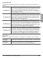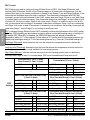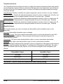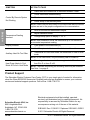
1
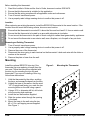
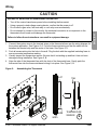
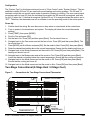
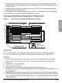
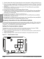
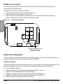
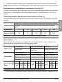
S1B14481
Rev. 01, 08/2011
Instruction Bulletin
Wiser™ EER56100 Thermostat Installer’s Guide
Retain for future use.
Description
The EER56100 is a precision digital thermostat for heating and cooling systems with 24 Vac control
wiring. The EER56100 thermostat supports the following systems:
Single-stage conventional heat/cool
Two-stage conventional (two-stage heat / two-stage cool)
Heat pump and geothermal heat pump (two-stage heat / single-stage cool)
Two-speed heat pump and geothermal two-speed heat pump (three-stage heat / two-stage cool)
Dual fuel heat pump and geothermal dual fuel heat pump
Humidifier and dehumidifier control
ENGLISH
•
•
•
•
•
•
The EER56100 thermostat can be controlled locally and, as an energy management device, remotely
with a ZigBee® radio interface. It offers programmability, stand-alone operation, and communication
with utility systems and personal computers.
•
•
Electrical rating:
24 V; 2 A; 50/60 Hz
Maximum current: 2 A on any circuit, 3 A total
Safety Precautions
This section contains important safety precautions that must be followed before attempting to install,
maintain, or troubleshoot electrical equipment. Carefully read and follow the safety precautions below.
DANGER
HAZARD OF ELECTRIC SHOCK
• Apply appropriate personal protective equipment (PPE) and follow safe electrical work
practices. See NFPA 70E.
• This equipment must be installed and serviced by qualified electrical personnel.
• Turn off all electrical power supplying this equipment before working on or inside the equipment.
• Always use a properly rated voltage sensing device to confirm that power is off.
• Replace all devices, doors, and covers before turning on power to this equipment.
Failure to follow these instructions will result in death or serious injury.
Installation Requirements
1. This equipment must be installed in accordance with all applicable codes and ordinances.
2. CE requirements must be observed for installation in Europe.
© 2011 Schneider Electric All Rights Reserved
™
Before installing this thermostat:
1.
2.
3.
4.
5.
Read this Installer’s Guide and the User’s Guide, document number S1B14479.
Ensure that this thermostat is suitable for the application.
Ensure that the wiring complies with all applicable codes and ordinances.
Turn off control transformer power.
Use a properly rated voltage sensing device to confirm that power is off.
Location
When replacing an existing thermostat, install the EER56100 thermostat in the same location. If the
location does not meet the following criteria, choose a new location:
ENGLISH
1.
2.
3.
4.
Ensure that the thermostat is mounted 5 ft. above the floor and is at least 2 ft. from an exterior wall.
Ensure that the thermostat is located in an area with adequate air circulation.
Do not mount the thermostat in the path of direct sunlight or radiant heat generated by appliances.
Do not mount the thermostat on an exterior wall, near a fireplace, or in the path of any air ducts.
Removing an Existing Thermostat
1.
2.
3.
4.
Turn off control transformer power.
Use a properly rated voltage sensing device to confirm that power is off.
Remove the cover of the thermostat.
Disconnect the wires going to each terminal on the thermostat. Label each wire with the letter or
number at the terminal.
5. Remove the plate or base from the wall.
Mounting
Install the optional EER5700 trim ring if the
thermostat you are replacing is larger than the
new one. Follow the instructions supplied with
the trim ring for mounting the trim ring and
thermostat. If you are not installing a trim ring,
follow these instructions.
Figure 1:
Mounting the Thermostat
1. Hold the thermostat by the sides, avoiding
the keys, and unsnap the base from the face.
2. Holding the base to the wall so that the word
“UP” is upright and facing you, mark the two
mounting holes on the wall using a pencil.
3. Using a 3/16 in. diameter drill bit, drill a hole
at the mounting hole markings.
4. Install the two wall anchors supplied.
5. Slide the system wires through the opening
in the base.
6. Mount the base to the wall using the two
#6 x 1/2 in. self-tapping screws supplied.
See Figure 1.
2-EN
© 2011 Schneider Electric All Rights Reserved
Wiring
CAUTION
HAZARD OF IMPROPER OR UNINTENDED OPERATION
Turn off the control transformer power before installing the thermostat.
Using a properly rated voltage sensing device, confirm that the power is off.
Do not short a gas valve, fan heat relay or cool relay even momentarily.
Do not attempt to connect to live circuits. An accidental connection to a component on the
thermostat circuit board could damage the thermostat.
Failure to follow these instructions can result in equipment damage.
1. Connect the system wires to the terminal strips on the thermostat base per the wiring diagram for
the system application. See Figures 3–9. Form the thermostat wiring so that the cable lies flat
between the terminal strip and the center of the base. See Figure 2, A.
2. Push all excess wiring into the hole in the wall. Plug the hole with the supplied insulating foam to
ensure accurate temperature reading.
3. Visually inspect the temperature sensor. Be sure that it is standing up and that it has not been
damaged during installation. See Figure 2, B.
4. Align the tabs of the thermostat face with the slots of the thermostat base. Gently push the
thermostat face into the thermostat base locking it into place. See Figure 2, B.
Figure 2:
Assembling the Thermostat
A
© 2011 Schneider Electric All Rights Reserved
SLOT
TAB
BASE
TEMPERATURE
SENSOR
B
WALL
3-EN
ENGLISH
•
•
•
•
TYPICAL WIRING DIAGRAMS
Figure 3:
Test and Configuration Power-up
UP
ENGLISH
JUMPER
3
2
1
24 Vac Common
24 Vac "HOT"
For HVAC systems with a single transformer for
heating and cooling, leave the metal jumper
between Terminal 1 (RC) and Terminal 2 (RH) in
place.
(C)
(RC)
THERMOSTAT
24 VAC
CONTROL
TRANSFORMER
Notes:
1. For HVAC systems with a single transformer for heating and cooling, leave the metal jumper
between Terminal 1 (RC) and Terminal 2 (RH) on the left terminal strip must in place. See Figure 3.
2. The EER56100 thermostat is factory-configured to control a single stage conventional HVAC
system.
3.
4.
5.
6.
— If the HVAC system is a heat pump, dual fuel heat pump, or if the thermostat is connected to a
zone control system that requires a sub-base, before operating the thermostat, configure the
“System Type” settings under “System Options.” See “Setup and Configuration” on page 16.
— If the HVAC system is a two-stage conventional or two-speed heat pump, before operating the
thermostat (making a call for heat or cool), configure the “Cool Stages” and “Heat Stages”
settings under “Stage Settings.” See “Setup and Configuration” on page 16.
When configured as a conventional thermostat, by default this thermostat does not turn the fan on
with a call for heat. If the furnace requires the thermostat to turn the fan on with a call for heat,
configure the “System Mode” to “Fan On With Heat” under “System Options.”
A conventional thermostat can be configured for automatic changeover heat/cool, manual
changeover heat/cool, heat only, or cool only thermostat. Refer to the “Configuration” steps
associated with the wiring diagram for the HVAC system type.
If the thermostat or HVAC system does not perform as stated in the “Power Up” steps under the
wiring diagram for the HVAC system type, recheck all wiring. See “Troubleshooting” on page 23.
For HVAC systems with separate heating and cooling transformers, remove the metal jumper
between Terminal 1 (RC) and Terminal 2 (RH) on the left terminal strip. See Figure 4 on page 5.
4-EN
© 2011 Schneider Electric All Rights Reserved
Figure 4:
Connections for Heat and Cool Transfers—Applies to All Systems
For HVAC systems
with separate heating
and cooling
transformers, remove
the metal jumper
between Terminal 1
(RC) and Terminal 2
(RH) on the left
terminal strip.
REMOVE
JUMPER
3
2
1
24 Vac Common
24 VAC
HEAT
TRANSFORMER
(C)
24 Vac Heat "HOT" (RH)
24 Vac Cool "HOT" (RC)
24 VAC
COOL
TRANSFORMER
THERMOSTAT
Single-Stage Conventional
Figure 5:
Connections for Single-Stage Heat/Cool Thermostat
UP
12
11
* Common wire is
required in “heat
only” or “cool only”
applications. Also
use a common if the
heat, cool, or fan
relay cannot supply
15 mA to the power
thermostat without
activating.
8
7
6
HVAC SYSTEM
Dehumidifier
(D)
Dehumidifier
Humidifier
(H)
Humidifier
(G)
Fan Relay
Fan
Cool
(Y1)
Cool Relay
Heat
(W1)
Heat Relay
3
24 Vac Common*
1
24 Vac "HOT"
(C)
(RC)
THERMOSTAT
24 VAC
CONTROL
TRANSFORMER
Configuration
The EER56100 is factory configured as a single-stage conventional heat/cool thermostat. In the factory
configuration, the thermostat does not turn the fan on with a call for heat. If the furnace does not turn the
fan on with a call for heat, the thermostat must be configured to do so under “System Options.”
© 2011 Schneider Electric All Rights Reserved
5-EN
ENGLISH
UP
Power Up
ENGLISH
1. Double check the wiring. Be sure there are no stray wires or wire strands at the connections.
2. Turn on power to the transformer and system. The display will show the current thermostat
settings.
3. Press [TEMP], then press [MORE].
4. Scroll to Fan and press [OK].
5. Set the fan to On. Press [OK] and then press [Back]. The fan should turn on.
6. Navigate back to the Fan screen and set the fan to Auto. Press [OK] and then press [Back]. The
fan should turn off.
7. Press [MORE], scroll to Mode, and press [OK]. Set the mode to Heat. Press [OK] and then press
[Back].
8. Raise the desired heat setting above the current temperature. Ensure that the heating unit turns on.
9. Navigate back to the Mode screen and set the mode to Off. Press [OK] and then press [Back]. The
heating unit should turn off.
10. Navigate back to the Mode screen and set the mode to Cool. Press [OK] and then press [Back].
Lower the desired cool setting below the current temperature. Ensure that the cooling unit turns on.
11. Navigate back to the Mode screen and set the mode to Off. Press [OK] and then press [Back].
Ensure that the cooling unit turns off.
12. Navigate back to the Mode screen and set the mode to Auto. Press [OK] and then press [Back].
The EER56100 thermostat works with most single-stage conventional 4-wire HVAC systems (without a
transformer common). However, if the thermostat resets when calling for heat or cool, or if the heat, cool,
or fan relay cannot supply 15 mA to power thermostat without the relay activating, the transformer
common wire or the Wiser Thermostat Auxiliary Power Supply (Part Number EER57100) is required.
Single-Stage Conventional for Zone Control Systems
Figure 6:
Connections for Single-Stage Thermostat for Zone Control Systems
UP
12
11
10
8
7
6
4
3
1
(D)
Dehumidifier
Humidifier
(H)
Humidifier
Cool Mode
(Y2)
Fan
System Cool Mode
(G)
Fan Relay
Cool
(Y1)
Zone Cool
Heat
(W1)
Zone Heat
Heat Mode
(W2)
System Heat Mode
24 Vac Common
24 Vac "HOT"
(C)
(RC)
THERMOSTAT
6-EN
ZONE CONTROLLER
Dehumidifier
24 VAC
CONTROL
TRANSFORMER
© 2011 Schneider Electric All Rights Reserved
Configuration
The “System Type” for this thermostat must be set to “Zone Control” under “System Options.” The two
additional outputs (W2 and Y2) are used with zoned heating and cooling systems. The W2 and Y2
terminals control the one control panel mode of operation (heating or cooling). The zone control panel
recognizes calls for heat (W) from the individual zones when the W2 terminal is energized, and calls
for cool (Y) when the Y1 terminal is energized. Neither W2 nor Y2 is energized when the mode is set to
“OFF.” Therefore, the thermostat can act as a Master to set the operating mode of the entire system.
1. Double check the wiring. Be sure there are no stray wires or wire strands at the connections.
2. Turn on power to the transformer and system. The display will show the current thermostat
settings.
3. Press [TEMP], then press [MORE].
4. Scroll to Fan and press [OK].
5. Set the fan to On. Press [OK] and then press [Back]. The fan should turn on.
6. Navigate back to the Fan screen and set the fan to Auto. Press [OK] and then press [Back]. The
fan should turn off.
7. Press [MORE], scroll to Mode, and press [OK]. Set the mode to Heat. Press [OK], then press [Back].
8. Raise the desired heat setting above the current temperature. Ensure that the heating unit turns on.
9. Navigate back to the Mode screen and set the mode to Off. Press [OK] and then press [Back]. The
heating unit should turn off.
10. Navigate back to the Mode screen and set the mode to Cool. Press [OK] and then press [Back].
Lower the desired cool setting below the current temperature. Ensure that the cooling unit turns on.
11. Navigate back to the Mode screen and set the mode to Off. Press [OK] and then press [Back].
Ensure that the cooling unit turns off.
12. Navigate back to the Mode screen and set the mode to Auto. Press [OK] and then press [Back].
Two-Stage Conventional (2-Stage Heat / 2-Stage Cool)
Figure 7:
Connections for Two-Stage Conventional Thermostat
UP
12
11
10
8
7
6
4
3
1
Dehumidifier
Humidifier
Cool 2
Dehumidifier
(H)
Humidifier
(Y2)
(G)
Fan
HVAC SYSTEM
(D)
Cool 2 Relay
Fan Relay
Cool 1
(Y1)
Cool 1 Relay
Heat 1
(W1)
Heat 1 Relay
Heat 2
(W2)
Heat 2 Relay
24 Vac Common*
24 Vac "HOT"
(C)
(RC)
THERMOSTAT
© 2011 Schneider Electric All Rights Reserved
24 VAC
CONTROL
TRANSFORMER
7-EN
ENGLISH
Power Up
Configuration
•
•
•
The “System Type” for this thermostat must be set to “Conventional” under “System Options.”
In the default configuration, this thermostat does not turn the fan on with a call for heat. If the
furnace does not turn the fan on with a call for heat, the thermostat must be configured to do so
under “System Options.”
The “Cool Stages” and “Heat Stages” settings must be configured under “Stage Settings.”
Power Up
ENGLISH
1. Double check the wiring. Be sure there are no stray wires or wire strands at the connections.
2. Turn on power to the transformer and system. The display will show the current thermostat
settings.
3. Press [TEMP], then press [MORE].
4. Scroll to Fan and press [OK].
5. Set the fan to On. Press [OK] and then press [Back]. The fan should turn on.
6. Navigate back to the Fan screen and set the fan to Auto. Press [OK] and then press [Back]. The
fan should turn off.
7. Press [HOLD] and select On to override Energy Efficient Control.
8. Press [MORE], scroll to Mode, and press [OK]. Set the mode to Heat. Press [OK] and then press
[Back].
9. Raise the desired heat setting one degree above the current temperature. Ensure that Stage 1 heat
turns on. After a few minutes, raise the desired heat setting three degrees above the current
temperature. Stage 2 heat should turn on.
10. Navigate back to the Mode screen and set the mode to Off. Press [OK] and then press [Back]. The
heating unit should turn off.
11. Navigate back to the Mode screen and set the mode to Cool. Press [OK] and then press [Back].
Lower the desired cool setting 1 degree below the current temperature. Ensure that Stage 1 cool
turns on. After a few minutes, lower the desired cool setting 3 degrees below the current
temperature. Stage 2 cool should turn on.
12. Navigate back to the Mode screen and set the mode to Off. Press [OK] and then press [Back].
Ensure that the cooling unit turns off.
13. Navigate back to the Mode screen and set the mode to Auto. Press [OK] and then press [Back].
14. Press [HOLD] and select Off to enable Energy Efficient Control.
About Heat Pump Systems
1. Terminal 5 (O) is energized for cooling.
Terminal 6 (B) is energized for heating.
In most applications, the reversing valve is energized for cooling and should be connected to the
“O” terminal. If the heat pump requires the reversing valve to be energized for heating, connect the
reversing valve to the “B” terminal.
2. With a call for Stage 2 on a two-speed heat pump, both compressor outputs Y1 and Y2 are
energized. When 2 stages of cooling and 2 stages of heating are configured for a heat pump,
Stage 2 is considered high speed and not auxiliary heat. If auxiliary heat (or emergency heat) is
needed, configure 3 stages of heating.
3. To temporarily disable Energy Efficient Control and heat as quickly as possible, press [HOLD] and
select “On.” The EER56100 thermostat will use the Auxiliary Heat as needed to reach the heat
setting.
8-EN
© 2011 Schneider Electric All Rights Reserved
4. Terminal 9 (L) is used to indicate a fault with the heat pump compressor. When a compressor fault
is detected, the display will flash red and the “Heat Pump Fault” error message will be displayed.
5. The Emergency Heat Relay (E Terminal) and outdoor thermostats (usually accessories to a heat
pump), are not used. The EER56100 thermostat automatically controls auxiliary heat efficiently. If
the heat pump is equipped with an outdoor thermostat, remove it from the auxiliary heat circuit.
About Dual Fuel Heat Pump Systems
1. When used with dual fuel heat pumps, the EER56100 thermostat requires a method for obtaining the
outdoor temperature. A Wiser Thermostat External Temperature sensor (EER57200) can be
physically connected to the “Remote Temp. Sensor” terminals on the thermostat, or the EER56100
thermostat can obtain the outdoor temperature from a remote system.
If the EER56100 thermostat cannot obtain the outdoor temperature, the heat pump compressor
will not operate and the thermostat will only call for the auxiliary heat until the problem is resolved.
When this occurs, the display will flash red and the “Problem With Outdoor Temperature Sensor.
Some Heat Stages May Be Disabled” error message will be displayed. After the error has been
acknowledged, “Outdoor Sensor Fault” will be displayed in the Message Bar until the problem is
resolved.
2. Balance Setpoint Limits:
— If the outdoor temperature is above the “Upper Balance Setpoint” (45 °F by default), the heat
pump is used exclusively.
— If the outdoor temperature falls below the “Upper Balance Setpoint” but is above the “Lower
Balance Setpoint” (35 °F by default), and if the heat pump is unable to heat at a rate of 5
degrees per hour or better, the heat pump will turn off and auxiliary heat will be used until the
call for heat has been satisfied.
— If the outdoor temperature falls below the “Lower Balance Setpoint”, the heat pump will turn off
and the auxiliary heat will be used until the call for heat has been satisfied.
— The Balance Setpoint Limits can be adjusted according to the manufacturer's specifications.
3. When the EER56100 thermostat makes a call for auxiliary heat, the heat pump compressor is
turned off and the auxiliary heat is used exclusively.
© 2011 Schneider Electric All Rights Reserved
9-EN
ENGLISH
A dual fuel heat pump typically has a gas furnace combined with a heat pump. The gas furnace is used
as auxiliary heat unless the outdoor temperature is very low, in which case it is used as the primary
heat source.
Heat Pump (2-Stage Heat / 1-Stage Cool)
Figure 8:
Connections for Heat Pump Thermostat
UP
12
11
ENGLISH
9
8
7
6
5
4
3
(D)
Dehumidifier
Humidifier
(H)
Humidifier
Ground Fault
(L)
Fault Relay
Fan
(G)
Fan Relay
Compressor
(Y1)
Compressor Relay
Energized in Heat
(B)
Energized in Cool
(O)
Reversing Valve
(W2)
Aux Heat Relay
Auxiliary Heat
24 Vac Common*
1
HVAC SYSTEM
Dehumidifier
24 Vac "HOT"
(C)
(RC)
THERMOSTAT
24 VAC
CONTROL
TRANSFORMER
Configuration
•
•
The “System Type” for this thermostat must be set to “Heat Pump” under “System Options.”
The “System Type” for this thermostat must be set to “Dual Fuel Heat Pump” for a dual fuel system
(Terminal “W2” is connected to the “W” or “W1” on the furnace).
Power Up
1. Double check the wiring. Be sure there are no stray wires or wire strands at the connections.
2. Turn on power to the transformer and system. The display will show the current thermostat
settings.
3. Press [TEMP], then press [MORE].
4. Scroll to Fan and press [OK].
5. Set the fan to On. Press [OK] and then press [Back]. The fan should turn on.
6. Navigate back to the Fan screen and set the fan to Auto. Press [OK] and then press [Back]. The
fan should turn off.
7. Press [HOLD] and select On to override Energy Efficient Control.
8. Press [MORE], scroll to Mode, and press [OK]. Set the mode to Heat. Press [OK] and then press
[Back].
9. Raise the desired heat setting 1 degree above the current temperature. Ensure that the heat pump
turns on in heating mode. After a few minutes, raise the desired heat setting 3 degrees above the
current temperature. Auxiliary heat should turn on. After a few minutes, set the mode to “EM Heat”.
The heat pump should stop, but the auxiliary heat should remain on.
10. Navigate back to the Mode screen and set the mode to Off. Press [OK] and then press [Back].
Ensure that both the heat pump and auxiliary heat turn off.
10-EN
© 2011 Schneider Electric All Rights Reserved
11. Navigate back to the Mode screen and set the mode to Cool. Press [OK] and then press [Back].
Lower the desired cool setting below the current temperature. Ensure that the heat pump turns on
in cooling mode.
12. Navigate back to the Mode screen and set the mode to Off. Press [OK] and then press [Back].
Ensure that the cooling unit turns off.
13. Navigate back to the Mode screen and set the mode to Auto. Press [OK] and then press [Back].
14. Press [HOLD] and select Off to enable Energy Efficient Control.
Two Speed Heat Pump (3-Stage Heat / 2-Stage Cool)
Connections for Two-Speed Heat Pump Thermostat
UP
12
11
10
9
8
7
6
5
4
3
(D)
Dehumidifier
Humidifier
(H)
Humidifier
Comp Stage 2 Relay
Ground Fault
(L)
Fault Relay
Fan
(G)
Fan Relay
Compressor Stage 1(Y1)
Energized in Heat
Energized in Cool
Auxiliary Heat
24 Vac Common*
1
HVAC SYSTEM
Dehumidifier
Compressor Stage 2(Y2)
24 Vac "HOT"
ENGLISH
Figure 9:
Comp Stage 1 Relay
(B)
(O)
Reversing Valve
(W2)
Aux Heat Relay
(C)
(RC)
THERMOSTAT
24 VAC
CONTROL
TRANSFORMER
Configuration
•
•
The “System Type” for this thermostat must be set to “Heat Pump” under “System Options.”
The “Cool Stages” and “Heat Stages” settings must be configured under “Stage Settings.”
Power Up
1. Double check the wiring. Be sure there are no stray wires or wire strands at the connections.
2. Turn on power to the transformer and system. The display will show the current thermostat
settings.
3. Press [TEMP], then press [MORE].
4. Scroll to Fan and press [OK].
5. Set the fan to On. Press [OK] and then press [Back]. The fan should turn on.
6. Navigate back to the Fan screen and set the fan to Auto. Press [OK] and then press [Back]. The
fan should turn off.
7. Press [MORE], scroll to Mode, and press [OK]. Set the mode to Heat. Press [OK], then press [Back].
8. Raise the desired heat setting 2 degrees above the current temperature. Ensure that the heat pump
turns on in heating mode. Press [HOLD] and select “On” to override Energy Efficient Control. Stage 2
heat should turn on.
© 2011 Schneider Electric All Rights Reserved
11-EN
ENGLISH
9. Raise the desired heat setting 3 degrees above the current temperature. Auxiliary heat should turn on.
10. After a few minutes, navigate back to the Mode screen and set the mode to “EM heat.” Press [OK]
and then press [Back]. Both stages of the heat pump should turn off, but the auxiliary heat should
remain on.
11. Navigate back to the Mode screen and set the mode to Off. Press [OK] and then press [Back].
Ensure that the auxiliary heat turns off.
12. Press [HOLD] and select Off to enable Energy Efficient Control.
13. Navigate back to the Mode screen and set the mode to Cool. Press [OK] and then press [Back].
Lower the desired cool setting 2 degrees below the current temperature. Ensure that the heat
pump turns on in cooling mode.
14. Press [HOLD] and select “On”. Stage 2 cool should turn on.
15. Navigate back to the Mode screen and set the mode to Off. Press [OK] and then press [Back].
Ensure that the cooling unit turns off.
16. Navigate back to the Mode screen and set the mode to Auto. Press [OK] and then press [BACK].
17. Press [HOLD] and select Off to enable Energy Efficient Control.
Accessory Connections for Use with Remote Systems
This thermostat has been preprogrammed with energy saving program schedules. When used with a
remote system, Schneider Electric recommends that the Program Mode be configured as “None” or
“Occupancy.” This will disable the internal program schedules.
Setting The Communications Jumper
This thermostat comes from the factory with the communications jumper (J8), labeled “COMM
JUMPER” on the thermostat printed circuit board, installed. See Figure 10.
•
•
When connecting to a Home Automation, Inc. (HAI) Home Control system or remote switch, this
jumper must be installed.
When connecting to a PC or other device with a serial port, this jumper must be removed.
Figure 10:
Communications Jumper
65A01 –
Rev
SN
COMM JUMPER
J8
COMMUNICATIONS
JUMPER
12-EN
© 2011 Schneider Electric All Rights Reserved
Use with HAI Home Control Systems
The thermostat can be connected to a Home Automation, Inc. (HAI) Home Control system. The HAI
controller can send commands to the thermostat to change mode, cool setting, heat setting, status of
fan and hold, and other items.
Run a three or four-conductor wire from the HAI system to the thermostat location. All thermostats on
an HAI Home Control system are connected to Ground, Zone +16, and Output 8. See Figure 11.
Figure 11:
Connections to HAI Home Control Systems
CONTROLLER
+Z12-
7
+Z13-
GND
+Z14-
GRN RED BRN GRY
PHONE
+Z15-
THERMOSTAT
UP
ENGLISH
5 GND 6
UTS
Z16Black
Green
Yellow
COMMUNICATIONS
JUMPER
Notes:
1. Connect additional thermostats in parallel. They may be connected in home-run or daisy chain
configuration.
2. When connecting to an HAI Home Control system, the communications jumper (J8), labeled
“COMM JUMPER” on the thermostat printed circuit board, must be in place.
3. Connect all thermostats on an HAI controller to the GRN (Green), BLK (Black), and YEL (Yellow)
terminals under the section marked “TSTAT.”
4. Contact HAI for more information.
© 2011 Schneider Electric All Rights Reserved
13-EN
Remote Setback Switch
The thermostat can be connected to a remote switch to toggle the heat and cool temperature settings
between preset setpoints. A signal can be sent from the remote switch location to change the
thermostat temperature settings from the Occupancy Day temperature settings to the Occupancy
Night temperature or Away settings. To use this mode, the “Program Options” setting must be set to
“Occupancy.” See “Program Options” on page 18.
Run a two-conductor wire from the remote switch to the thermostat location. Make the connections to
the Black and Green terminals under the section marked “Comm” on the right terminal strip. See
Figure 12.
Figure 12:
Connections to a Remote Setback Switch
ENGLISH
ANY SYSTEM WITH
A RELAY OR
5–15 VDC
OUTPUT
THERMOSTAT
UP
Black
Green
5–15
Vdc
COMMUNICATIONS
JUMPER
Notes:
1. When connecting to a remote setback switch, the communications jumper (J8), labeled “COMM
JUMPER” on the thermostat printed circuit board, must be in place.
2. When 0 Vdc is applied, the desired temperature settings will change to the preset Occupancy Day
temperature settings.
3. When 5–15 Vdc is applied, the desired temperature settings will change to the preset Occupancy
Night temperature or Away settings.
Other Systems
For connections to personal computers, utility management systems, and other automation systems,
refer to connection diagrams provided with personal computer software package or other system.
14-EN
© 2011 Schneider Electric All Rights Reserved
Remote Temperature Sensor
A Wiser Thermostat External Temperature Sensor (EER57200) can be installed to monitor the
temperature from a remote location or can be combined with the onboard temperature sensor for the
average temperature of two locations.
•
•
•
•
For distances up to 100 ft., typical twisted pair, PVC-insulated, shielded cable may be used.
For distances from 100–150 ft., twisted pair with polypropylene insulated conductors, shielded
must be used.
For distances from 150–250 ft., twisted pair with foam-polyethylene insulated conductors, shielded
must be used.
Wire runs must not exceed 250 ft.
Make the connections to the Green and Black terminals under the section marked “Remote Temp
Sensor” on the right terminal strip. See Figure 13.
Figure 13:
Connections to a Remote Temperature Sensor
THERMOSTAT
UP
SHIELD
Green
Black
TWO CONDUCTOR
SHIELDED CABLE
SHIELD
COMMUNICATIONS
JUMPER
Notes:
1. When connecting a remote temperature sensor, tie together the shield and one of the wires from
the remote temperature sensor and connect them to the Black terminal. See Figure 13.
2. At the location of the temperature sensor, wrap the shield around the jacket of the cable and tape.
3. Configure the temperature sensor according to the application. See “Temperature Sensors” under
Installation Settings.
© 2011 Schneider Electric All Rights Reserved
15-EN
ENGLISH
Run a twisted pair, shielded cable from the EER56100 thermostat to the remote temperature sensor
location.
Disable Local Control
The Task Buttons and Scroll Wheel on the thermostat can be disabled to prevent anyone from
controlling the thermostat locally.
To disable the Task Buttons and Scroll Wheel:
1. Remove the thermostat face from the thermostat base.
2. Remove the local control jumper. See Figure 14.
3. Align the tabs of the thermostat face with the slots of the thermostat base. Gently push the
thermostat face into the thermostat base, locking it into place.
Figure 14:
Local Control Jumper
ENGLISH
65A01 –
Rev
SN
COMM JUMPER
J8
TO DISABLE TASK BUTTONS
AND SCROLL WHEEL,
REMOVE JUMPER.
Setup and Configuration
The time and date are automatically set from the ZigBee® network or can be set manually if there is no
network connection. See the User’s Guide, document S1B14479.
Installation Settings
This section describes the items that the installer must setup as part of the thermostat installation. The
Installation Settings menu is used to configure the operating parameters of the thermostat.
To access Installation Settings:
1.
2.
3.
4.
5.
From the Home screen, press and hold the Scroll Wheel for 3 seconds.
Highlight “Setup” and press [OK] or the Scroll Wheel.
Press and hold the left two buttons and the Scroll Wheel simultaneously.
Highlight “Installation Settings” and press [Select] or the Scroll Wheel.
Read the warning and press [Continue] to proceed.
16-EN
© 2011 Schneider Electric All Rights Reserved
6. To exit the Installation Settings menu, press [Back] several times to return to the Home Screen.
NOTE: The thermostat will automatically default to the Home screen after 3 minutes of no key activity.
Thermostat Address (with HAI Home Control Systems. See Page 13.)
If remote communications will be used and more than one thermostat will be installed, each thermostat
must be set to a unique address. The default address setting is 1. An address from 1–127 may be
selected.
Communications Mode (with HAI Home Control Systems. See Page 13.)
*Serial: RS-232 mode for use with personal computers and automation systems.
Communications Day/Night: The thermostat remotely communicates with a remote setback
switch.
System Baud
*100
300
1200
2400
9600
Expansion Baud
100
300
*1200
2400
9600
An asterisk (*) next to a setup item indicates the default (factory) setting.
System Options
Before operating the thermostat, the “System Type” and “System Mode” must be configured. The
thermostat can be configured with the following system options.
System Type
System Mode
Fan On with Heat
Stage
*Conventional
Dual Fuel Heat Pump1
Heat Pump
Zone Control
Geothermal Dual Fuel
Heat Pump1
Geothermal Heat Pump
*Auto Changeover
Auto Changeover
Auto Changeover
Manual Changeover
Manual Changeover
Manual Changeover
Heat Only
—
—
Cool Only
—
—
*None
1
2
3
1
and
2
1
and
3
2
and
3
1, 2,
and
3
*1, 2,
and
3
1
2
3
1
1
2
and and and
2
3
3
*1, 2,
and
3
1
2
3
1
1
2
and and and
2
3
3
An asterisk (*) next to a setup item indicates the default (factory) setting.
1
When configured, an additional Installer Setup menu item (Balance Setpoints) is added to the list.
© 2011 Schneider Electric All Rights Reserved
17-EN
ENGLISH
The thermostat can communicate with remote systems in different modes. The following modes are
available:
Program Options
This thermostat has been preprogrammed with energy saving program schedules. When used with a
remote system, Schneider Electric recommends that the Program Mode be configured as “None” or
“Occupancy.” This will disable the internal program schedules. The program options setting
determines the method for scheduling temperature change commands.
*Schedule: Program setpoints are based on time of day and day of week.
None:
Program
Mode
The internal program schedule is disabled. Use this when connected to a
remote system for temperature change commands.
ENGLISH
Occupancy: Program setpoints are based on the occupancy status of a remote system.
Status options are Day, Night, Away, and Vacation. This mode is also used
with a remote setback switch. NOTE: A remote system or switch is required.
An asterisk (*) next to a setup item indicates the default (factory) setting.
Calibration Offset
Calibration Offset is used to raise or lower the current temperature reading from the onboard
temperature sensor by 0.5 °F or 0.25 °C. The default setting is 0.00. The minimum calibration offset is
-14.5 °F and the maximum calibration offset is + 14.5 °F.
Cool/Heat Limits
Setpoints are used to limit the desired temperature settings in cool and heat mode. The desired cool
setting can never be set below the “Cool Setpoint Min.” setting, and the desired heat setting can never
be set above the “Heat Setpoint Max.” setting. The default setting for cool is 51 °F; cool setpoint
minimum is 48 °F, and cool setpoint maximum is 91 °F. The default setting for heat is 91 °F; heat
setpoint minimum is 45 °F, and heat setpoint maximum is 88 °F.
18-EN
© 2011 Schneider Electric All Rights Reserved
Cool/Heat Min On/Off
Cool Minimum On
The number of minutes the thermostat forces the cooling system to remain on
before turning off. Raising this number will increase the total time the cooling
system is on, but may allow the temperature to drift farther from setpoint.
When combined with Cool Minimum Off, cycles per hours can be obtained by
using the following calculation:
60 / (Cool Minimum On + Cool Minimum Off). The default time is 6 minutes.
Cool Minimum Off
The number of minutes the thermostat forces the cooling system to remain off
before starting again. Raising this number will increase the total time that the
cooling system is off, but may allow the temperature to drift farther from the
setpoint. When combined with Cool Minimum On, cycles per hours can be
obtained by using the following calculation:
60 / (Cool Minimum On + Cool Minimum Off). The default time is 6 minutes.
Heat Minimum On
The number of minutes the thermostat forces the heat to remain on before
turning off. Raising this number will increase the total time the heating system
is on (saving energy), but may allow the temperature to drift farther from the
setpoint (decreasing comfort). When combined with Heat Minimum Off, cycles
per hours can be obtained by using the following calculation:
60 / (Heat Minimum On + Heat Minimum off). The default time is 6 minutes.
Heat Minimum Off
The number of minutes the thermostat forces the heat to remain off before
starting again. Raising this number will increase the total time that the heating
system is off (saving energy), but may allow the temperature to drift farther
from the setpoint (decreasing comfort). When combined with Heat Minimum
On, cycles per hours can be obtained by using the following calculation:
60 / (Heat Minimum On + Heat Minimum off). The default time is 6 minutes.
Stage Settings
NOTE: Before operating the thermostat, the “Cool Stages” and “Heat Stages” must be configured.
Cool Stages
The number of cool stages the HVAC system can support. The default setting
is 1.
Heat Stages
The number of heat stages the HVAC system can support. Auxiliary heat is
included in this number for heat pumps. The default setting is 1.
© 2011 Schneider Electric All Rights Reserved
19-EN
ENGLISH
Cool/Heat Min On/Off are used to limit the on and off times of the cooling and heating system (in
minutes).
EEC Control
EEC Settings are used to configure Energy Efficient Control (EEC), 2nd Stage Differential, and
Auxiliary Heat Differential. Not all of these features apply to all thermostat configurations. Only the
features that apply to the current configuration (based on the System Type and Stage Settings) of the
thermostat are available when this menu is selected. This thermostat is equipped with EEC that
continually monitors the performance of the HVAC system and uses Stage 2 (heat or cool) and Stage
3 (auxiliary heat) only when necessary. If the thermostat determines that Stage 1 is able to heat or cool
at a rate of 5° per hour or better, Stage 2 will not be used. If Stage 1 is unable to heat or cool at this
rate, the thermostat will use Stage 2 as needed. Under these conditions, Stage 1 will run continuously
and Stage 2 will cycle on and off as needed. In extremely cold conditions, the auxiliary heating will be
used when Stage 1 and/or Stage 2 is not heating at a sufficient rate.
ENGLISH
EEC: configures Energy Efficient Control. EEC continually monitors the performance of the HVAC system
and uses a PID algorithm and auto balance routine to achieve comfort while saving energy. A setting of 0
will disable EEC. When EEC is disabled, the EER56100 thermostat will attempt to maintain the
temperature within 0.5 °F of the setpoint. A lower setting of 2–3 can be used for slow reacting sources (e.g.,
radiant heat) and higher setting of 7–8 for fast reacting sources (e.g., forced air). The default setting is 5.
2nd Stage Differential: determines how far from the setpoint the temperature must be before the
second stage turns on.
Auxiliary Heat Differential: determines how far from the setpoint the temperature must be before the
auxiliary heat turns on. This is only available for heat pump systems.
Start Delay (Minutes): sets the minimum amount of time the heating system must run before the
Auxiliary Heat Stage is used. To use start delay, EEC must be enabled and Hold must be off.
Conventional (1 Cool / 1 Heat)
Zone Control (1 Cool / 1 Heat)
Heat EEC
Cool EEC
*5
*5
0–10
0–10
—
Heat Pump and Dual Fuel Heat Pump
(1 Cool / 2 Heat)
Heat EEC
EEC
Cool EEC
Settings Aux Heat Differential
Start Delay (Minutes)
*5
*5
*2
*5
0–10
0–10
1–10
0–4 hr:15 min
Heat Pump and Dual Fuel Heat Pump
(2 Cool / 3 Heat)
Conventional (2 Cool / 2 Heat)
Heat EEC
EEC
2nd Stage Differential
Start Delay (Minutes)
*5
*5
*2
*10
Geothermal Heat Pump and Geothermal
Dual Fuel Heat Pump (1 Cool / 2 Heat)
Heat EEC
Cool EEC
Aux Heat Differential
Start Delay (Minutes)
*5
*5
*2
*45
0–10
0–10
1–10
0–4 hr:15 min
Geothermal Heat Pump and Geothermal
Dual Fuel Heat Pump (2 Cool / 3 Heat)
Heat EEC
*5 0–10
Heat EEC
*5
Cool EEC
*5 0–10
Cool EEC
*5
2nd Stage Differential *1 1–10
2nd Stage Differential *1
Start Delay (Minutes) *5 0–4 hr:15 min Start Delay (Minutes) *45
Aux Heat Differential *2 1–10
Aux Heat Differential *2
Start Delay (Minutes) *10 0–4 hr:5 min Start Delay (Minutes) *3 hr
An asterisk (*) next to a setup item indicates the default (factory) setting.
20-EN
0–10
0–10
1–10
0–4 hr:15 min
0–10
0–10
1–10
0–4 hr:15 min
1–10
0–4 hr:15 min
© 2011 Schneider Electric All Rights Reserved
Anticipator Control
The Anticipator Control settings are used to anticipate the need to turn the system on or off before the
temperature is actually at the setting.
People perceive temperature as a combination of heat in the air and heat radiated from the walls and
surroundings. The thermostat also measures a combination of air and wall temperature. When
heating, the air temperature rises faster than the wall temperature. The thermostat turns the heat off
briefly to prevent overheating the air while the wall temperature catches up.
Because of the PID algorithm and auto balance routine which monitors the performance of the HVAC
system, the anticipator settings are automatic by default. However, the anticipator settings may be
adjusted if desired.
Heat Anticipator: adjusts the tendency of the thermostat to turn the heating unit off before the desired
heat setting is reached. This is done to avoid overheating the air while the walls and furniture catch up.
A setting of 0–4 is intended for fast reacting heating systems, such as forced air. A setting of 6–10 is
intended for slow reacting heating systems, such as radiant heat. A setting of 5 is used for automatic
anticipation.
A lower setting decreases the tendency to turn off the heating system before the desired heat setting is
reached. If the heating system response time is slower, as are most radiant heating systems, a higher
number will help maintain an even space temperature.
Cool Anticipator: adjusts the tendency of the HVAC to run the cooling system to refresh and
dehumidify the air before the temperature rises to the desired cool settings. A setting of 0–4 is
intended for more humid climates and increases the tendency for the cooling system to turn on to
refresh and dehumidify the air. A setting of 6–10 is intended for dry climates and decreases the
tendency to run the cooling system below the cooling setting. A setting of 5 is used for automatic
anticipation.
2nd/3rd Stage Extended On: When enabled and if any 2nd or 3rd stage turns on, it will remain on until
the heat/cool is satisfied, regardless of the settings for any stage differentials. The default setting is off.
Cool Anticipator
*5
Heat Anticipator
*5
2nd/3rd Stage Extended On
*Off
An asterisk (*) next to a setup item indicates the default (factory) setting.
© 2011 Schneider Electric All Rights Reserved
21-EN
ENGLISH
When cooling, the thermostat periodically runs the cooling system to circulate the air and remove
humidity when the temperature is close to, but not above the desired cool setting.
Temperature Sensors
The Temperature Sensor settings are used to configure the internal temperature sensor and optional
remote temperature sensors that are connected to the thermostat. Any temperature sensors that are
set as the same type (for example, indoor or outdoor) will display the average temperature reading
among the sensors.
Internal Sensor: Enables or disables the onboard temperature sensor for indoor use only. *Enabled.
External Sensor 1: Enables the external temperature sensor for indoor or outdoor use. All indoor and
outdoor temperatures are averaged between all sensors of the same type. *Disabled.
External Sensor 2: Enables the expansion module temperature sensor for indoor or outdoor use. All
indoor and outdoor temperatures are averaged between all sensors of the same type. *Disabled.
ENGLISH
External Sensor 3: Enables the expansion module temperature sensor for indoor or outdoor use. All
indoor and outdoor temperatures are averaged between all sensors of the same type. *Disabled.
Humidity Options
The Humidity Options are used to configure the dehumidifier and/or humidifier output on the
thermostat.
Not Used: Dehumidifier/Humidifier output is disabled.
Fan Speed Control: This option uses the dehumidifier output to control the fan speed on an HVAC
system with a variable speed fan. When energized, the fan speed is reduced to augment the
dehumidification process.
Dehumidifier: This option uses the dehumidifier output to control a stand-alone dehumidifier.
Humidifier: This option uses the humidifier output to control a stand-alone humidifier.
EM Heat: EM Heat is displayed if the respective output is configured as an Emergency Heat Output as
described under Emergency Heat Options. If configured as an Emergency Heat Output, the output
cannot be modified under Humidity Options; it must first be reconfigured under Emergency Heat
Options.
Dehumidifier Output
Humidifier Output
*Not Used
*Not Used
Dehumidifier
Humidifier
Fan Speed Control
EM Heat
An asterisk (*) next to a setup item indicates the default (factory) setting.
22-EN
© 2011 Schneider Electric All Rights Reserved
Emergency Heat Options
The Emergency Heat Options are used to reconfigure the H (Humidifier) or D (Dehumidifier) outputs
on the EER56100 thermostat to activate Emergency Heat mode. The default address setting is
“None.”
None: The H (Humidifier) and D (Dehumidifier) output will operate as described under Humidity
Options on page 22.
D Terminal: This option configures D (Dehumidifier) output on the EER56100 thermostat to activate
when the thermostat is in Emergency Heat mode.
Factory Default
This option restores all system settings and programming to factory configuration. Read the warning
and then press [Yes] to proceed or [Cancel] to return to Installation Settings.
Troubleshooting
DANGER
HAZARD OF ELECTRIC SHOCK
Apply appropriate personal protective equipment (PPE) and follow safe electrical work practices.
See NFPA 70E.
Failure to follow these instructions will result in death or serious injury.
SYMPTOM
Thermostat Inoperative
Heat or Cool Inoperative
ACTION TO TAKE
1.
Check power to the thermostat.
2.
Check wiring.
1.
Check for break in W or Y wire.
2.
Allow minimum off time to pass.
3.
Check system options for correct settings.
4.
If arrow is blinking, wait until startup delay expires.
5.
Mode is Off (Select Heat, Cool, or Auto).
6.
Remote system is overriding thermostat.
Continued on next page
© 2011 Schneider Electric All Rights Reserved
23-EN
ENGLISH
H Terminal: This option configures H (Humidifier) output on the EER56100 thermostat to activate when
the thermostat is in Emergency Heat mode.
SYMPTOM
Control By Remote System
Not Working
ACTION TO TAKE
1.
Check wires and connections to the section marked “Comm.”
2.
Check thermostat address setting.
3.
Check communications mode setting.
4.
Check setup of the remote system.
NOTE: Ensure that all setup items for the thermostat and the remote
system are set to the proper configurations for communication.
1.
ENGLISH
Temperature Reading
Incorrect
Allow 30 minutes for thermostat to adjust.
2.
Adjust calibration offset.
3.
Change setup option to display °F or °C.
NOTE: After installation, allow the thermostat up to 30 minutes for
an accurate temperature reading.
Display Problem
Auxiliary Heat On Too Often
1.
Cycle power to the thermostat (R).
1.
Heat Pump is not able to meet load due to cold weather.
2.
Thermostat is in EM Heat mode. Set thermostat to Heat or Auto
mode.
NOTE: In EM Heat mode, only the auxiliary heat is turned on.
1.
Heat Pump Heats In Cool
Mode & Cools In Heat Mode
Reversing valve is connected to wrong terminal. Move the wire
from B to O or from O to B.
NOTE: The wires connecting the reversing valve may be reversed.
See Note 1 on page 9.
Product Support
The Schneider Electric Customer Care Center (CCC) is your single point of contact for information
about the Wiser EER56100 thermostat. Qualified personnel are available to answer your customer
service and technical support questions. Call toll free 1-888-778-2733.
Schneider Electric USA, Inc.
8001 Knightdale Blvd.
Knightdale, NC 27545 USA
1-888-778-2733
www.schneider-electric.us
24-EN
Electrical equipment should be installed, operated,
serviced, and maintained only by qualified personnel. No
responsibility is assumed by Schneider Electric for any
consequences arising out of the use of this material.
S1B14481 Rev. 01,08/2011 Replaces S1B14481, 05/2011
© 2011 Schneider Electric All Rights Reserved
© 2011 Schneider Electric All Rights Reserved