1
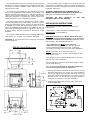
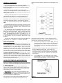
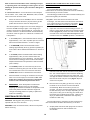
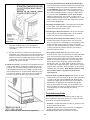
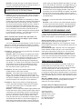
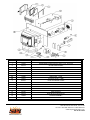
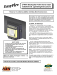
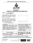
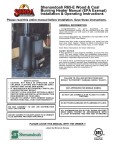
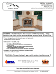
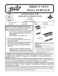
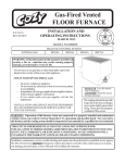
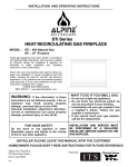
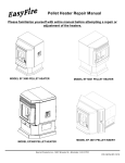
EF4001B AutoLite Pellet Stove Insert
Installation & Operating Instructions
Please read this entire manual before installation. Save these instructions.
PLEASE READ THIS ENTIRE M ANUAL BEFORE
INSTALLATION AND USE OF THIS PELLET FUELBURNING ROOM HEATER. FAILURE TO FOLLOW
T H ES E IN S T R U C T IO N S C O U L D R E S U L T IN
GENERAL INFORMATION
Installation and repair should be done by a qualified
service person. The heater should be inspected before use
and at least annually by a professional service person. More
frequent cleaning m ay be required due to fuel quality,
excessive lint from carpeting, bedding m aterial, etc. It is
im perative that control com partm ents, burn pot and circulating air passageways of the heater be kept clean.
The EASYFIRE Pellet Insert has been designed and
approved for burning w ood pellet fuel only. Burning solid
fuel in other form s is not perm itted and will void all warranties.
This unit has been approved for use with a Ø 3" Type L
Pellet Vent System or Stainless Chimney Liner (Ø 4" on
runs 10 feet and above).
SAFETY NOTICE
< CAUTION: HOT W HILE IN OPERATION. KEEP
CHILDREN, CLOTHING AND FURNITURE AW AY.
CONTACT M AY CAUSE SKIN BURNS.
< IF THIS HEATER IS NOT PROPERLY INSTALLED,
A HOUSE FIRE M AY RESULT.
< CONTACT LOCAL BUILDING OFFICIALS ABOUT
RESTRICTIONS AND INSTALLATION INSPECTION REQUIREM ENTS IN YOUR AREA.
< FAILURE TO COM PLY W ITH OW NERS' M ANUAL
INSTRUCTIONS W ILL VOID YOUR W ARRANTY!
NOTE: This heater should not be installed in
a bedroom or bathroom.
NEVER use gasoline, gasoline-type lantern fuels,
kerosene, charcoal lighter fluid, or sim ilar liquids to start or
"freshen up" a fire. Keep all such liquids well away from the
heater while it is in use.
Ashes m ust be disposed of in a m etal container with a
tight fitting lid and placed on a noncom bustible floor or
ground, well away from all fuels, pending final disposal.
NOTE : During the first few burns the high tem perature
paint and sealant used in m anufacture will em it som e odor
and sm oke. Open doors and windows to the outside for
proper ventilation during the first burn cycle and curing of
the paint.
This heater, when installed, m ust be electrically grounded in
accordance with local codes or, in the absence of local
codes, with the National Electrical Code, ANSI/NFPA 702006.
INSTALLER: PLEASE LEAVE THIS MANUAL WITH THE OWNER!!
Sierra Products, Inc.
5061 Brooks St., Ste B
Montclair, CA 91763
(909) 399-3355
Listed by OMNI-Test
Laboratories, Inc.
Report No. 256-S-01-4
Provide adequate clearances around air openings into the
combustion cham ber and adequate accessibility clearance for
servicing and proper operation. Never obstruct the front
opening of the heater.
Use only listed Type "L" pellet vent or stainless liner and
com ponents for installation. Failure to use listed com ponents
will void your warranty. See pipe m anufacturer instructions for
installation instructions.
The heater m ay be installed as a free-standing unit m ounted on a noncom bustible protective floor pad or hearth, or it
m ay be m ounted into an existing U. L. approved wood stove
chim ney using a Hearth Extension (p/n 11099). Non-com bustible floor protection is required and m ust be used when
placing the heater on any com bustible m aterial.
OUTSIDE COM BUSTION AIR IS M ANDATORY IN
M OBILE OR M ODULAR HOM E INSTALLATIONS. SEE
SECTION ON OUTSIDE AIR INSTALLATION.
C AU T IO N : D O N O T C O N N E C T
DISTRIBUTION DUCT OR SYSTEM .
The pellet heater m ust be operated with a power source
and will not operate using natural draft. If there is a power
failure the heater will shut down. If the 12 volt back-up system
is installed, the heater will autom atically switch to 12 volt
power. An optional backup battery is available for the unit
which lasts approxim ately 48 hrs on high and 72 hrs on low.
A bigger battery m ay be purchased if desired for longer
durations.
TO
AN Y
AIR
INSTALLATION INSTRUCTIONS
Check with local building officials for specific code
requirem ents.
A listed, type "L" Pellet Vent Pipe or Stainless Liner is
MANDATORY on all installations.
The EasyFire Pellet Heater has been listed by OMNI-Test
Laboratories, Inc. to ASTM, U.L.,and EPA Standards.
W ARNING: Installation of a Mobile Attachment Home
Kit P/N 10412 and outside combustion air is mandatory
in mobile or modular home installations although it m ay
also be used in all residential applications.
CAUTION: Do not connect this unit to a chim ney flue serving
another appliance.
An outside air inlet M UST be provided for
combustion and ventilation air. The air inlet m ust
rem ain unrestricted while unit is in use. Outside air
connection is located in the rear of the heater (Figure 1).
EF4100 Overall Dimensions
NOTE: Vent Pipes’ inner diameters may vary.
For Vent Pipes Ø3.00" or smaller, use SPI Exhaust Vent
Adapter p/n 11076.
This adapter is used on Selkirk Metalbestos™ and other
Ø2.950" I.D. Pellet Vent Pipes.
Use conduit pipe or m etal flex pipe and/or fittings to m ake
the air intake hook-up.
Also, the structural integrity of the mobile home floor,
w alls and ceiling/roof must be maintained.
1. Clean and inspect the fireplace and its chim ney for any
structural defect that m ay cause any future problem s.
Secure gas piping that is installed with a cap and verify
there are no leaks. Seal ash dum p or any other access to
the firebox area. Fix the dam per in an open position or
rem ove it as required for vent pipe installation.
2. Verify the required hearth and side and clearances to
m antels (fig. 2 & 3).
Figure 2
2
NOTE: THE INSERT W EIGHT IS SUBSTANTIAULLY
FRONT HEAVY AND IF NOT FULLY SUPPORTED IT
COULD FALL FORW ARD.
Figure 5
4. Install vent system into existing chim ney by using 3" flex
from left side of hearth, passing dam per and continuing to
the top of the chim ney. If the total vent length is longer than
10 Feet, install Ø4" vent from that point to top of chim ney
(Figure 6).
Figure 3
3. If the hearth and fireplace floor are not at the sam e
elevation, leveling legs m ay be installed on the rear of the
unit (Figure 4) for distances of up to 1". For larger
distances shim m ing m ay be used using a non-com bustible
m aterial. A Hearth Base Support is available from your
dealer for installations where the hearth is below the
fireplace opening (Figure 5).
Figure 6
5. Pack fiberglass insulation around the vent pipe and
com bustion air duct. Install a flashing cover over
chim ney. Secure flashing and seal as required. Install
listed vent cap and secure.
6. Measure fireplace opening and adjust hopper top to the
required level allowing for installation clearance. This is
accom plished by rem oving the four #8 screws on the sides
and rear of unit and raising the top by 1" increm ents until
desired height and reinstalling screws (Figure 4).
Figure 4
7. Slide insert into fireplace and center. Level as required,
then secure vent to outlet on left side of insert. Connect
com bustion air duct and secure.
3
Note - For best insert operation the flexible vent
installation should not have any tight bends. Try to
achieve a smooth sw eep to the vertical rise.
IM PORTANT - Any electrical work perform ed on the
EASYFIRE Heater should be done by qualified personnel.
Remote Control Thermostat Installation:
SURROUND INSTALLATION
The rem ote therm ostat is designed to autom atically
regulate the room tem perature from the control panel heat
setting to the “Off” setting based upon room tem perature
and placem ent of the rem ote therm ostat. Rem em ber to
leave the control panel on the "Medium or High" position
when utilizing the wall therm ostat feature.
The surround supplied with the insert is adjustable in
height so as to allow for m any installation perim eters.
1. After the insert is in position, install left and right surround
sides by attaching them to the two side brackets using the
four 1/4-20 bolts provided. The retainer nuts on the
surround sides m ay be installed at any vertical position to
accom m odate the installation.
The following is a step by step procedure for installing the
optional rem ote therm ostat. Note connection term inals on
rear of unit (Figure 7).
2. Slide the surround top panel between the hopper top and
cover. Push the panel down until the screw holes align
with the side legs. Install the (4) #8 screws provided.
Install power cord into the receptacle on the right side of
the insert. Route cord behind surround leg and out to a
ground plus.
a. Unplug heater from wall outlet and 12VDC power!
b. Mount m illivolt style rem ote receiver box to rear of
stove using double-sided tape.
b. Rem ove factory jum p wire and hook up therm ostat
wires to term inals (Figure 7).
d. Reconnect AC power and follow instructions with
rem ote therm ostat regarding set up.
AUTOLITE INSTALLATION INSTRUCTIONS
The AutoLite System is factory installed with the only
installation requirem ents being the optional therm ostat.
IM PORTANT - Any electrical work perform ed on the
EASYFIRE Heater should be done by qualified personnel.
Autolite W iring Diagram
Figure 7 Connection Panel Low er Right Side
DOOR HANDLE ASSEMBLY
Wall Thermostat Installation:
The door handle and latch m ust be assem bled and
adjusted prior to the operation of the stove.
The wall therm ostat is designed to autom atically regulate
the room tem perature from the control panel heat setting to
the “Off” setting based upon room tem perature. Rem em ber
to leave the control panel on the "Medium or High" position
when utilizing the wall therm ostat feature.
1. Position handle assem bly through door and secure with
collar by sliding over shaft and tightening with allen
wrench provided.
2. Position latch on end of shaft with flat facing allen screw.
Depending on gasket, shaft will protrude approx. 1/4"
through back of latch collar. Snug allen screw.
The following is a step by step procedure for installing the
optional wall therm ostat. Note connection term inals on left
side of unit at rear (Figure 7). Use 18/2 therm ostat wire for
the installation.
a. Unplug heater from wall outlet and 12VDC power!
b. Rem ove factory jum p wire and hook up therm ostat
wires to term inals (Figure 7).
c. Locate therm ostat approxim ately 10 to 12 feet from
heater or in area that requires steady tem perature.
d. Run therm ostat wires from heater to therm ostat along
wall or under carpet etc. and hook wires to
therm ostat term inals. On new construction you can,
of course, run wire in the walls before sheet rock or
paneling is done.
e. Reconnect AC power.
f.
Figure 9
Door handle assembly
3. To adjust door, close and turn handle so latch contacts
striker. Door gasket m ust contact firm ly against front face
of unit. This can be checked by closing against a piece of
paper. Firm ly tug on paper, if it m oves with solid
resistance the door is properly adjusted.
Make sure all wiring is com pleted before plugging the
EASYFIRE Heater back into the wall outlet.
4
1. A chim ney connector shall no pass through and attic or
roof space, closet or sim ilar concealed space, or a floor,
or ceiling.
UNIT ELECTRIC CONNECTIONS
Route the power supply cord from lower right side of unit
to a grounded three prong 120VAC receptacle. Care should
be taken to m ake sure the fireplace and hearth does not
pinch or otherwise dam age the cord.
2. W here a chim ney passage through a wall, or partition of
com bustible construction is desired, the installation shall
conform the CAN/CSA-B365.
OPTIONAL 12V HOOK-UP & OPERATION
3. Maintain an effective vapour barrier at the location where
the chim ney or other com ponent penetrates to the
exterior of the structure by sealing with high tem perature
silicone.
1. The EASYFIRE 12V back up can be purchased as an
option and includes the following com ponents:
a. Deep cycle sealed 12V battery.
4. Clearance to com bustibles m ay only be reduced by
m eans approved by the regulatory authority.
b. Battery connector cables for hook-up to the heater.
2. In order to hook-up the battery and engage the 12V
backup system sim ply connect red cable to red term inal
on the heater (see Figure 6) and to positive connector on
battery [the term inal m arked (+)] and connect the black
cable to the black term inal on the heater and to the
negative connector on the battery (the term inal m arked
(-). If you hook up the cables backwards the red LED
light above the term inal receptacles will com e on. If
hooked up properly this LED will glow green.
5. Store pellet fuels in a dry area away from unit. Do not
store fuels within the space heater installation clearances
or within the space required for charging and ash
rem oval.
6. Adequate ventilation air is required to operate this heater.
During operation the heater draws air for com bustion
which can be assisted by the installation of outside
com bustion air inlets. However, certain weather
conditions such as icing or use of kitchen exhaust fans
m ay im pact and reduce the effectiveness of vents. It is
im portant to note that room air starvation well negatively
im pact the operation of the heater.
W ARNING - M AKE SURE RED CABLE GOES TO RED
TERM INAL (POSITIVE CONNECTOR) AND BLACK
CABLE GOES TO BLACK TERM INAL (NEGATIVE
CONNECTOR).
7. If power outages with battery backup or room air
starvation occurs during operation of heater, sm oke in
the house m ay result. This m ay trigger sm oke detectors
if they are installed.
3. If you decide to purchase your own 12V back up system
we recom m end a sealed gel cell battery. Failure to install
the proper battery could cause physical harm to you and
your property and will also void the heater warranty.
AUTOLITE OPERATION
4. W hen the battery is properly connected and the heater
plugged in, the following will happen autom atically:
Your EASYFIRE Pellet Stove is equipped with the Autolite
Autom atic ignition and operating system .
a. The heater will autom atically switch to 12V power if
there is a power failure, and switch back when power
is restored.
The AutoLite system is integrated into the stove to allow for
autom atic start up using a heating elem ent located in the
burn pot. This elem ent starts the initial fire required to burn
the wood pellets. The system operates on 120VAC power
supplied through a separate fuse and runs for five m inutes
during the initial stove start up. After the five m inute period
the AutoLite system is deactivated and the stove operates
based on the EasyFire digital control system requirem ents.
If the house AC power should quit, the AutoLite system will
not be available however, with the optional battery attached
the stove can be m anually lit and operate on battery power
for several days (depending on battery size, refer to the
EasyFire installation m anual).
b. The battery will be trickle charged as long as the
heater is plugged into 110 AC wall outlet. Do not use
extension cords. The trickle charge will not recharge
a low or dead battery but it will keep a charged
battery at m axim um perform ance.
5. If you choose to separate the battery from the heater by
lengthening the cables you m ust m ake sure that the
cable wire used will carry the current to the heater. For
exam ple, if the distance is 10 to 20 feet then 12 gauge
wire m ust be used. Check with your local electrical
professional to m ake sure you have used the proper
gauge wire/cable.
The m ost effective installation of the EasyFire AutoLite
Stove is to connect the unit to a therm ostat. This can be
accom plished using a standard wall therm ostat or a rem ote
control therm ostat. A rem ote control therm ostat can be
purchased from your local dealer and installed in a few
m inutes. This will allow the stove to start and shut down
when there is a call for heat.
a. Unplug heater from wall outlet and 12VDC power!
b. Mount m illivolt style rem ote receiver box to rear of
stove using double-sided tape.
If your house power is out the AutoLite system will not be
able to start the stove when the therm ostat calls for heat.
However if the stove is operating when the power goes out
the stove will not shut down operating on the backup
battery. Your EasyFire will turn down to low when the
therm ostat calls for shut down and then turn up to the
setting on the control panel when the therm ostat calls for
heat. A true back up heat source!
b. Rem ove factory jum p wire and hook up therm ostat
wires to term inals (Figure 7).
d. Reconnect AC power and follow instructions with
rem ote therm ostat regarding set up.
CANADIAN REQUIREMENTS
If this unit is being installed in Canada, the following
additional requirem ents m ust be m eant:
5
attem pt to operate heater if glass becom es dam aged in any
way!
GENERAL WARNINGS
The EASYFIRE Pellet Stove and Insert has been
designed and approved for burning w ood pellet fuel only.
Burning solid fuel in other form s is not perm itted and will
void all warranties.
NEVER use gasoline, gasoline-type lantern fuels,
kerosene, charcoal lighter fluid, or sim ilar liquids to start or
"freshen up" a fire. Keep all such liquids well away from the
heater while it is in use.
Ashes m ust be disposed of in a m etal container with a
tight fitting lid and placed on a noncom bustible floor or
ground, well away from all fuels, pending final disposal.
This heater, when installed, m ust be electrically grounded in
accordance with local codes or, in the absence of local
codes, with the National Electrical Code, ANSI/NFPA 702006.
Provide adequate clearances around air openings into the
com bustion cham ber and adequate accessibility clearance for
servicing and proper operation. Never obstruct the front
opening of the heater.
The pellet heater m ust be operated with a power source
and will not operate using natural draft. If there is a power
failure the heater will shut down. If the 12 volt back-up system
is installed, the heater will autom atically switch to 12 volt
power. An optional backup battery is available for the unit
which lasts approxim ately 48 hrs on high and 72 hrs on low.
A bigger battery m ay be purchased if desired for longer
durations.
2. AutoLite Control Functions: Control functions on the
Easyfire are as follows: OFF, FAN, LOW , MEDIUM, HIGH,
CLEAN. Here is how each function works:
The EasyFire Pellet Heater has been listed by OMNI-Test
Laboratories, Inc. to ASTM, U.L.,and EPA Standards.
FUEL SELECTION
A.
Proper fuel selection is im portant for overall operation. Your
stove operates best with 1/4" diam eter wood pellets that are
no longer than 3/4" long. The pellets should be specifically
m anufactured for use pellet heaters. Use of fuel nonconform ing fuel will cause the stove to operate erratically.
Additionally, a low ash content of below 1% is required and
will reduce your cleaning and m aintenance tim e. Store pellets
in a clean dry area. Do not use pellets that have been dam p
or have a m oisture level above 5%.
The quality of pellet fuel varies from brand to brand. This will
affect the efficiency of your heater. W e suggest that you try
several brands until you find one that gives you a clean efficient burn. Poor quality pellets will burn rich with black soot
and ash will accum ulate quickly. Quality pellets will burn clean
and ash build up will be m inim al.
W hen the Control Button is turned to FAN, a tim er is
activated and you will have about ten (10) m inutes to
get the pellets lit and reach a m inim um tem perature.
This function is used for m atch lighting when the AC
power is out.
Should the pellets not light in 10 m inutes sim ply turn the
button to OFF and begin again. This will give you
another 10 m inutes to get the pellets lit. The reason for
the tim er function is so that the heater will autom atically
shut down if the fire goes out. Pellets do not feed in the
FAN position.
B.
In the LOW position, the EASYFIRE will be feeding
approxim ately 1 to 1½ lbs. of pellets per hour and the
flam e will fluctuate between 1" and 6" in height.
AUTOLITE START-UP AND OPERATION
Refer to Installation and Operation manual provided with
the unit for standard m atch lighting and 12V operations.
1. AutoLite Start-Up:
Prior to operating your AutoLite stove, m ake sure the
hopper is full of wood pellets and the interior com ponents
have been installed properly including; burn screen & pot,
heat exchange covers, and ash drawer.
IM PORTANT: The Fire Pot m ust be seated flush and
m ust sit even in the pot tray. Air leaking around the Fire Pot
will create a poor burn (Figure 11). Light the pellets in Fire
Pot using any approved pellet lighter.
Figure 11
Note: Caution m ust be taken when installing burn pot or
operating door not to dam age ceram ic glass. Do not
6
C.
W ARNING: Risk of electrical shock, disconnect all AC/DC
power before servicing.
In the M EDIUM position the EASYFIRE will be
feeding approxim ately three (3) pounds of pellets per
hour and the flam e will fluctuate between 3" and 8" of
fire.
D.
In the HIGH position the EASYFIRE will be feeding
approxim ately 4+ lbs. per hour and the flam e will
fluctuate between 3" and a full flam e. The fan speed
will increase accordingly as the heater autom atically
adjusts itself based on tem perature inside the heater
(see G below).
E.
The CLEAN position is to be used only when the
heater is not burning and you wish to clean out the
accum ulated ash in the front of the fire area. See
CLEAN OUT section of m aintenance instructions.
F.
After the heater is running for several hours and you
wish to turn it off sim ply press the button to OFF. The
heater will continue running until it cools dow n
and then will automatically shut itself dow n.
G.
REM EM BER: Each feed position will fluctuate
because the m icroprocessor is autom atically
adjusting the feed and air based on tem perature. This
m eans the pellet feed rate and flam e height will
change accordingly based on quality of pellet and
heat loss of dwelling.
ALW AYS TURN YOUR Heater OFF & LET IT COOL
BEFORE CLEANING.
Your EASYFIRE Pellet Heater requires routine
m aintenance for m axim um perform ance and is m andatory
for the warranty to rem ain in effect.
The following procedures should be studied carefully and
perform ed regularly as indicated:
1. Fly-ash: Som e ash will accum ulate in the heat
exchanger, Fire Pot and flue and should be cleaned out
on a regular basis for best efficiency and safety. W hen
the heater is shut down and cold, you should:
a. Open door and rem ove Heat Exchanger Cover. To
rem ove, sim ply slide up and out from retaining angle
bracket (Figure 12). Clean one side at a tim e. W ith
one slide cover rem oved, leave door open and turn
control button to the "CLEAN" position. Let heater
run until ash in Fire Pot area is vacuum ed out by
heater fan. Turn off and replace cover. Rem ove
rem aining cover and repeat procedure for the other
side. The vent pipe should be cleaned out after this
procedure. Rem ove the clean-out port cover (Figure
13) and vacuum as required.
3. Starting the Stove: Push a Heat Range button (Low or
Medium is best for start up) and turn the therm ostat up to
“Call for heat”. The stove fan will begin to operate along with
the ignitor cycle. After about a m inute the pellets will begin
to fall in the burn pot. After five m inutes there will be a fire in
the burn pot and the stove will begin to heat up. W hen the
stove reaches start up operating tem perature it will then
switch to the control panel setting and begin it’s autom atic
operation cycle.
b. Rem ove Fire Pot by lifting up and out, it m ay be
brushed out or vacuum ed. Fire Pot should be
cleaned weekly and depending on pellet quality daily.
Make sure holes in pot are not clogged. The area
around and below the pot should be checked every
five or six days depending on how m any hours a day
you are burning your heater and the quality of the
pellets being burned. (After a few days you will be
able to determ ine the frequency needed for clean
out.)
Prior to stove operating on thermostat, confirm proper
operation by servicing and adjusting the stove as
outlined in the “Installation Guide”. When servicing
stove, operate with therm ostat bypassed as stove will
reset to start up mode each time therm ostat is
activated.
The im portant thing to rem em ber is that excessive Flyash accum ulation will affect the efficiency of the burn.
c. Scrape pellet feed chute with putty knife to rem ove
hardened m aterial on which sawdust can
accum ulate.
Feed Trim Adjustment
d. The clean-out port cover should be rem oved and the
vent pipe checked every four to six weeks or
whenever you utilize the clean-out m ode on the
control dial.
Underneath the control button you will find a sm all round
button that will turn forward and reverse. This button can
adjust the feed m otor in the LOW operating position. By
turning the button clockwise you can increase the feed on
LOW and by turning it counterclockwise you can decrease
the feed in the LOW position. Factory setting is 1:00
o’clock.
e. Fly-ash can also accum ulate in the vent pipe and
term ination cap. Inspect exhaust system frequently to
m aintain free flow of exhaust fum es and fly-ash. The
frequency of clean-out depends entirely on the quality
of the pellets, so you will have to initially m onitor the
buildup in the pellet vent pipe.
Once the stove is at operating temperature for one hour
set the stove on LOW . Adjust the trim button so that
average flame is approx. 1-2" above the burn pot. This
w ill set the average feed rate (air/flue) for best
operation.
2. Hopper Clean Out: Vacuum the accum ulated saw dust
in the hopper weekly. Keep free of debris and foreign
m aterial. AN ACCUMULATION OF SAW DUST CAN
CAUSE IRREGULAR PELLET FEED. For best results
this should be done on a regular basis depending upon
how often the heater is used. If you burn the heater all
the tim e you should do this every eight to ten days.
M ove this button carefully! It is designed to fine tune
your LOW setting in the event you change brands of pellets
and/or live at a higher elevation. If this setting is to low the
stove m ay go out during LOW setting operations. If this
should happen increase the trim by sm all am ount.
3. Cleaning the Exhaust Fan Blade & Heat Exchanger:
The exhaust blower should be checked for excessive Flyash buildup. Regular and routine m aintenance utilizing
the CLEAN OUT feature will keep the exhaust blower
housing and fan blades clean. This cleaning can only be
done when the heater is NOT burning. For best results
MAINTENANCE PROCEDURE
CAUTION: Moving parts m ay cause injury, DO NOT
operate with rear cover rem oved.
7
run the fan in the CLEAN OUT position w ith the door
open for approxim ately one m inute or until ash is no
longer being picked up by the fan. Rem em ber, you m ust
always check the clean out cap on the tee after utilizing
the CLEAN OUT feature.
Solution: W hen the pellets are overfeeding, it usually
m eans that the air flow has been reduced. Check the Fire
Pot air intake holes to be sure they are clear. Check to
see if Fire Pot was properly seated in pot tray. Check to
see if the m anifold m ay have filled with Fly-ash. If you
use a low grade pellet, and clinkers (fused ash and dirt)
form in the bottom of the Fire Pot, it will choke the air
intake (you m ight consider changing the brand of pellets
to one that burns cleaner). You m ust let the fire go out
before rem oving and cleaning the Fire Pot.
4. Keeping the Glass Clean: If soot deposits accum ulate
on the glass, clean with window glass cleaner and a
paper towel when the glass is cold.
5. Polishing the Gold and Nickel: All chrom e and gold
plating used on the EASYFIRE heater can be cleaned
with a soft cloth and non-abrasive cleaner.
Never vacuum out the heater w hen the heater is in
operation! The hot ashes can lodge in your vacuum
cleaner and cause a fire!
6. Cleaning & Polishing Gold and Nickel Plated Parts:
Gold and Nickel is a soft m etal and therefore a fragile
surface. Prior to the first burn it is im portant to use
W index or com parable product and a soft clean cloth to
wipe any m arks off all gold surfaces or the heat will
cause the m arks to rem ain in the surface perm anently.
Always clean the gold surface when the heater is COOL.
You m ust clean the m anifold regularly in order to insure a
good air to fuel ratio, thus allowing the heater to "breathe"
properly. You m ust also check the vent pipe and tee to see
that they are not clogged and full of ash.
4. Problem : Heater was burning well and then soot began
form ing on the glass door.
7. Door glass replacem ent: Should the door glass
becom e broken it m ay be replaced by scraping the sealer
from around the outer edge of the glass. Carefully pry
glass from door fram e then clean all sealer from fram e.
Obtain a replacem ent glass from your local dealer and
attach glass to door using High Tem perature Silicon
Sealer (m in. 400 ° F). Apply sealer to all four corners of
the glass and set glass into fram e. Apply sealer to m ating
edge of glass and fram e. Allow two hours dry tim e before
installing door onto heater. Note: Replace with Corning
Pyro-Ceramic Glass only. Refer to parts list for
specifications.
Solution: Black soot form ing on the glass door m eans
that the com bustion is not right and the heater needs a
good clean out. Som e brands of pellets burn m uch richer
than others and you m ight have to change brands of
pellets and/or have the air/fuel settings re-adjusted by
your dealer. It is norm al to have the glass cloud up after
several hours of burning but it should wipe off with a
good window cleaner. If the glass turns black quickly,
then the heater needs a good clean out.
5. Problem : W e had a power failure and the heater
em itted sm oke for about five m inutes.
Troubleshooting Guide
Solution: If the heater em its sm oke during a power
failure, and you have frequent power failures then we
suggest you purchase the battery back-up system . If the
vent pipe is installed according to these instructions the
sm oke will syphon out of the pipe in m ost instances.
The following scenarios are provided in order to help you
locate a difficulty if the heater perform s in a m anner which
would seem to indicate a m alfunction:
l. Problem: I loaded the heater for start-up, pressed the
button and pellets started but the fire didn't keep going.
6. Problem : After several weeks of outstanding perform ance, the heater suddenly stopped and the red light
under the control button cam e on. This light is the Hi
Tem p/Flue Indicator Light.
Solution: Rem em ber that the tim er on start up runs
about 10 m inutes and if the heater has not heated up
enough to deactivate the tim er you will have to start over
by pressing the button to off and then back to MEDIUM
or HIGH.
Solution: The Hi-Tem p/Flue Indicator light indicates that
Fly-ash has built up in the exhaust system and/or there is
a restriction in the exhaust/flue system . Check the pipe
system for excessive ash and clogging, particularly the
vent cap. Rem ove the clean out cap on the tee and
m ake sure that ash has not blocked the exhaust air flow.
This autom atic shut down in case of flue clogging is a
safety feature and if the shut down occurs it m eans you
have a problem and should consult a service technician
and/or clean your pipe and heater thoroughly. If you feel
the Fly-ash build up is excessive, we suggest that you try
another brand. In m oist clim ates the pellets and Fly-ash
can actually absorb m oisture from the air and create
creosote and a severe clogging problem . Keep this in
m ind when you store and handle your pellets. The heater
warranty does not cover the quality of the fuels used or
the way they m ay be handled either before or after you've
purchased them .
EASYFIRE will automatically switch to 12 volt
provided you have the 12 volt battery option installed.
2. Problem: The heater was lit and burning properly, then
suddenly it stopped feeding pellets.
Solution: a) The therm ostat setting is to low and the has
called for the stove to shut down. b) Check pellet supply
in hopper. If em pty, fill and follow start-up procedure as
outlined in the beginning of this m anual. c) Occasionally,
a foreign object, debris or an excessive am ount of sawdust can enter the feed m echanism and jam the feed
chute. If this happens, you m ust em pty the hopper and
check the feed chute to see what is causing the jam .
Rem ove any foreign m aterial or object and re-start the
heater. CAUTION: Keep fingers and hands clear of feed
m echanism when heater is on.
7. Problem : I turned off the switch and the heater kept
running.
Solution: This is norm al. The exhaust blower will keep
running until it cools down and then it will autom atically
turn off. This can vary by the tem perature the exhaust
has reached and the tem perature of the cooling air.
3. Problem: The fire was burning well and then it began to
overfeed pellets and started backing up into the pellet
feed chute, sm othering the fire.
8
HI TEMP/FLUE AND TRIM INDICATORS:
W hen the Hi-Tem p/Flue indicator light com es on (red lite
beneath control button) it m eans that the flue is obstructed
or you have a reverse draft and gases cannot exit properly.
Maintenance is required and a thorough cleaning and pipe
check m ust be perform ed.
TRIM button : Underneath the control button you will find a
sm all round button that will turn forward and reverse. This
button can control the feed m otor in the LOW position only.
By turning the button clockwise you can increase the feed
on LOW and by turning it counterclockwise you can
decrease the feed in the LOW position.
M ove this button carefully! It is designed to fine tune
your LOW setting in the event you change brands of pellets
and/or live at a higher elevation.
DC OPERATION - BUILDING A FIRE AND
START-UP
IM PO RTANT (Gold Units Only): Gold is a soft m etal and
therefore a fragile surface. Prior to the first burn it is im portant
to use W index™ or com parable product with a soft clean cloth
to wipe any m arks off all gold surfaces.
If not cleaned prior to first burn, the heat m ay cause the m arks
to rem ain in the surface perm anently.
Alw ays clean the gold surface w hen the heater is COOL.
Figure 12
1. Filling the Hopper and Start-Up:
CAUTION: Fuel hopper lid m ust be closed before
operating unit. Maintain hopper seal in good condition.
DO NOT OVERFILL HOPPER! The EASYFIRE will hold
about 35 lbs. to 50 lbs. of pellets depending on hopper
height.
Allow pellets to burn for approxim ately 1 m inute, or until
pellet ignition has been achieved. Close door and turn the
control knob to the "FAN" position. Allow fire to burn for
several m inutes. W hen the pellets are well lit, turn the
control knob to "LOW " for approxim ately 10 m inutes then
turn up to "HI". W e recom m end that you run the heater on
“Medium ” or "HI" for about 30 m inutes in order to get the
heat exchanger hot before turning it to "LOW ". You will
need to burn the heater for a few hours before deciding
which setting is best for your particular needs.
Open the top lid and fill the hopper with pellets (Figure 9).
The quality of pellet fuel varies from brand to brand. This
will affect the efficiency of your heater. W e suggest that you
try several brands until you find one that gives you a clean efficient burn. Poor quality pellets will burn rich with black soot
and ash will accum ulate quickly. Quality pellets will burn clean
and ash build up will be m inim al.
Make sure hopper lid is fully closed. Open the front door.
Fill the Fire Pot with pellet fuel.
IM PORTANT: The Fire Pot m ust be seated flush and
m ust sit even in the pot tray. Air leaking around the Fire Pot
will create a poor burn (Figure 10). Light the pellets in Fire
Pot using any approved lighter fluid.
Figure 13
9
Note: Caution must be taken when installing burn pot
or operating door not to damage ceramic glass. Do not
attempt to operate heater if glass becomes damaged in
any way!
2. Control Functions: Control functions on the Easyfire
are as follows: OFF, FAN, LOW , MEDIUM, HIGH, CLEAN.
Here is how each function works:
A.
W hen the Control is set to FAN, a tim er is activated
and you will have about ten (10) m inutes to get the
pellets lit and reach a m inim um tem perature.
ALW AYS TURN YOUR Heater OFF & LET IT COOL
BEFORE CLEANING.
Your EASYFIRE Pellet Heater requires routine
m aintenance for m axim um perform ance and is m andatory
for the warranty to rem ain in effect.
The following procedures should be studied carefully and
perform ed regularly as indicated:
1. Fly-ash: Som e ash will accum ulate in the heat
exchanger, Fire Pot and flue and should be cleaned out
on a regular basis for best efficiency and safety. W hen
the heater is shut down and cold, you should:
Should the pellets not light in the 10 m inutes sim ply turn
the knob to OFF and begin again. This will give you
another 10 m inutes to get the pellets lit. The reason for
the tim er function is so that the heater will autom atically
shut down if the fire goes out. Pellets do not feed in the
FAN position.
B.
In the LOW position, the EASYFIRE will be feeding
approxim ately 1 to 1½ lbs. of pellets per hour and the
flam e will fluctuate between 1" and 6" in height.
C.
In the M EDIUM position the EASYFIRE will be
feeding approxim ately three (3) pounds of pellets per
hour and the flam e will fluctuate between 3" and 8" of
fire.
D.
In the HIGH position the EASYFIRE will be feeding
approxim ately 4 lbs. per hour and the flam e will
fluctuate between 3" and a full flam e. The fan speed
will increase accordingly as the heater autom atically
adjusts itself based on tem perature inside the heater
(see G below).
E.
The CLEAN position is to be used only when the
heater is not burning and you wish to clean out the
accum ulated ash in the front of the fire area. See
CLEAN OUT section of m aintenance instructions.
F.
After the heater is running for several hours and you
wish to turn it off sim ply turn the knob to OFF. The
heater will continue running until it cools dow n
and then will automatically shut itself dow n.
G.
REM EM BER: Each feed position will fluctuate
because the m icroprocessor is autom atically
adjusting the feed and air based on tem perature. This
m eans the pellet feed rate and flam e height will
change accordingly based on quality of pellet and
heat loss of dwelling.
a. Open door and rem ove Heat Exchanger Cover. To
rem ove, sim ply slide up and out from retaining angle
bracket (Figure 12). Clean one side at a tim e. W ith
one slide cover rem oved, leave door open and turn
control knob to the "CLEAN" position. Let heater run
Figure 14
until ash in Fire Pot area is vacuum ed out by heater
fan. Turn off and replace cover. Rem ove rem aining
cover and repeat procedure for the other side. The
vent pipe should be cleaned out after this procedure.
Rem ove the clean-out port cover (Figure 13) and
vacuum as required.
b. Rem ove Fire Pot by lifting up and out, it m ay be
brushed out or vacuum ed. Fire Pot should be
cleaned daily. Make sure holes in pot are not
clogged. The area around and below the pot should
be checked every five or six days depending on how
m any hours a day you are burning your heater and
the quality of the pellets being burned. (After a few
days you will be able to determ ine the frequency
needed for clean out.)
MAINTENANCE PROCEDURE
CAUTION: Moving parts m ay cause injury, DO NOT
operate with rear cover rem oved.
The im portant thing to rem em ber is that excessive Flyash accum ulation will affect the efficiency of the burn.
W ARNING: Risk of electrical shock, disconnect all power
before servicing.
c. Scrape pellet feed chute with putty knife to rem ove
hardened m aterial on which sawdust can
accum ulate.
10
3. Cleaning the Exhaust Fan Blade & Heat Exchanger:
The exhaust blower should be checked for excessive Flyash buildup. Regular and routine m aintenance utilizing
the CLEAN OUT feature will keep the exhaust blower
housing and fan blades clean. This cleaning can only be
done when the heater is NOT burning. For best results
run the fan in the CLEAN OUT position w ith the door
open for approxim ately one m inute or until ash is no
longer being picked up by the fan. Rem em ber, you m ust
always check the clean out tee after utilizing the CLEAN
OUT feature (Figure 13).
4. Keeping the Glass Clean: If soot deposits accum ulate
on the glass, clean with window glass cleaner and a
paper towel when the glass is cold.
5. Polishing the Gold and Chrom e: All chrom e and gold
plating used on the EASYFIRE heater can be cleaned
with a soft cloth and non-abrasive cleaner.
Figure 15
Front ash access
d. The clean-out port cover should be rem oved and the
vent pipe checked every four to six weeks or
whenever you utilize the clean-out m ode on the
control dial.
e. Fly-ash can also accum ulate in the vent pipe and
term ination cap. Inspect exhaust system frequently to
m aintain free flow of exhaust fum es and fly-ash. The
frequency of clean-out depends entirely on the quality
of the pellets, so you will have to initially m onitor the
buildup in the pellet vent pipe.
2. Hopper Clean Out: Vacuum the accum ulated saw dust
in the hopper weekly. Keep free of debris and foreign
m aterial. AN ACCUMULATION OF SAW DUST CAN
CAUSE IRREGULAR PELLET FEED. For best results
this should be done on a regular basis depending upon
how often the heater is used. If you burn the heater all
the tim e you should do this every eight to ten days.
6. Cleaning & Polishing Gold Plated Parts: Gold is a soft
m etal and therefore a fragile surface. Prior to the first
burn it is im portant to use W index or com parable product
and a soft clean cloth to wipe any m arks off all gold
surfaces or the heat will cause the m arks to rem ain in the
surface perm anently. Always clean the gold surface
when the heater is COOL.
7. Door glass replacem ent: Should the door glass
becom e broken it m ay be replaced by scraping the sealer
from around the outer edge of the glass. Carefully pry
glass from door fram e then clean all sealer from fram e.
Obtain a replacem ent glass from your local dealer and
attach glass to door using High Tem perature Silicon
Sealer (m in. 400 ° F). Apply sealer to all four corners of
the glass and set glass into fram e. Apply sealer to m ating
edge of glass and fram e. Allow two hours dry tim e before
installing door onto heater. Note: Replace with Corning
Pyro-Ceramic Glass only. Refer to parts list for
specifications.
8. Plenum clean out & draft adjustm ent: Access to clean
under the burn pot is through the plenum clean out plates
on right or left side low front (Figure 16). Rem ove the
fastener and plate and vacuum out ash accum ulations.
Additionally, the draft plate is accessible through this
opening and m aybe turned with a long standard screw
driver clockwise to reduce the draft through the burn pot.
This adjustm ent is m ade generally only during
installation.
Troubleshooting Guide
The following scenarios are provided in order to help you
locate a difficulty if the heater perform s in a m anner which
would seem to indicate a m alfunction:
Figure 16 Plenum Clean Out & Draft Adjustment
l. Problem : I loaded the heater for start-up, pressed “Low”
and the heater did not start.
Solution: Check power cord to see that it is plugged in.
Check 5 am p ignitor fuse. Replace if burned.
2. Problem : Heater starts slow with lots of sm oke.
11
and/or clean your pipe and heater thoroughly. If you feel
the Fly-ash build up is excessive, we suggest that you try
another brand. In m oist clim ates the pellets and Fly-ash
can actually absorb m oisture from the air and create
creosote and a severe clogging problem . Keep this in
m ind when you store and handle your pellets. The heater
warranty does not cover the quality of the fuels used or
the way they m ay be handled either before or after you've
purchased them .
Solution: a) Check burn pot for ash deposit. b) Check
burn pot is im properly placed and is seating on igniter. c)
Check air box clean out for ash build up.
The EASYFIRE will autom atically switch to 12 volt backup
provided you have the 12 volt option installed.
3. Problem: The fire was burning well and then it began to
overfeed pellets and started backing up into the pellet
feed chute, sm othering the fire.
Solution: W hen the pellets are overfeeding, it usually
m eans that the air flow has been reduced. Check the Fire
Pot air intake holes to be sure they are clear. Check to
see if Fire Pot was properly seated in pot tray. Check to
see if the m anifold m ay have filled with Fly-ash. If you
use a low grade pellet, and clinkers (fused ash and dirt)
form in the bottom of the Fire Pot, it will choke the air
intake (you m ight consider changing the brand of pellets
to one that burns cleaner). You m ust let the fire go out
before rem oving and cleaning the Fire Pot.
Never vacuum out the heater w hen the heater is in
operation! The hot ashes can lodge in your vacuum
cleaner and cause a fire!
You m ust clean the m anifold regularly in order to insure a
good air to fuel ratio, thus allowing the heater to "breathe"
properly. You m ust also check the vent pipe and tee to see
that they are not clogged and full of ash.
4. Problem: Heater was burning well and then soot began
form ing on the glass door.
Solution: Black soot form ing on the glass door m eans
that the com bustion is not right and the heater needs a
good clean out. Som e brands of pellets burn m uch richer
than others and you m ight have to change brands of
pellets and/or have the air/fuel settings re-adjusted by
your dealer. It is norm al to have the glass cloud up after
several hours of burning but it should wipe off with a
good window cleaner. If the glass turns black quickly,
then the heater needs a good clean out.
5. Problem: W e had a power failure and the heater
em itted sm oke for about five m inutes.
Solution: If the heater em its sm oke during a power
failure, and you have frequent power failures then we
suggest you purchase the battery back-up system . If the
vent pipe is installed according to these instructions the
sm oke will syphon out of the pipe in m ost instances.
6. Problem: After several weeks of outstanding perform ance, the heater suddenly stopped and the red light
under the control knob cam e on. This light is the Hi
Tem p/Flue Indicator Light.
Solution: The Hi-Tem p/Flue Indicator light indicates that
Fly-ash has built up in the exhaust system and/or there is
a restriction in the exhaust/flue system . Check the pipe
system for excessive ash and clogging, particularly the
vent cap. Rem ove the clean out cap on the tee and
m ake sure that ash has not blocked the exhaust air flow.
This autom atic shut down in case of flue clogging is a
safety feature and if the shut down occurs it m eans you
have a problem and should consult a service technician
7. Problem : I turned off the switch and the heater kept
running.
Solution: This is norm al. The exhaust blower will keep
running until it cools down and then it will autom atically
turn off. This can vary by the tem perature the exhaust
has reached and the tem perature of the cooling air.
HI TEMP/FLUE RED WARNING LIGHT:
W hen the Hi-Tem p/Flue indicator light com es on (red lite
beneath control knob) it m eans a fault has been detected in
either the flue system , over tem perature, or fan/feed m otor.
Slow Flash Red Light - Indicates a blocked flue. Check
flue and clean out for built up ash deposits.
Solid Red Light - Indicates an over tem perature. Check
the air intake at rear of unit. Turn the feed trim down 25% to
reduce fuel rate.
Fast Flash Red Light - Requires unit to be unplugged to
reset. Indicates a feed m otor jam or fan m otor fault. Fan
m otor test would require running unit on “fan and clean”
only to determ ine if red light indication is repeated. If not,
feed system is jam m ed and requires the hopper access
cover to be rem oved and jam m ed m aterial to be rem oved.
If this condition continuos contact your dealer for service.
TRIM KNOB ADJUSTMENT:
Underneath the control knob you will find a sm all round
knob that will turn forward and reverse. This knob can
control the feed m otor rate. By turning the knob clockwise
you can increase the burn rate and by turning it
counterclockwise you can decrease the burn rate. Use this
to change the overall rate for different pellets. For instance,
if the pellet has high ash and burns dirty decrease the "trim "
and if the heater goes out on low or has low flam e increase
the "trim ".
M ove this KNOB carefully! It is designed to fine tune your
LOW setting in the event you change brands of pellets
and/or live at a higher elevation.
Customer Service & Replacem ent Parts
Replacem ent parts are available from your local dealer or
on-line @ www.sierraproductsinc.net . Our call or write:
Custom er Service
Sierra Products, Inc.
5061 Brooks St. Ste. B
Montclair, CA 91763
Ph: 909-399-3355x21
Fax: 909-399-3357
12
ITEM No.
PART NUMBER
DESCRIPTION
1
110429
DOOR FRONT GLASS (Ceramic glass 11"x11 3/4"x5mm)
2
100119
GLASS FIBER GASKET
3
100125
DOOR FIBER ROPE GASKET
4
300536
FEED AUGER SYSTEM V3
5
300106
COMBUSTION BLOWER ASSEMBLY
6
120114
CONTROL BOARD V2.1
6A
110080
MAIN FUSE - 1 AMP
6B
110510
AUTOLITE FUSE - 5 AMP
7
200549
HEAT EXCHANGE COVER
8
110456
ASH DRAWER FIBER ROPE GASKET
9
110451
ASH DRAWER KNOB
10
120117
IGNITOR-200W
11
300512
BURN POT AL V2
12
120120
IGNITOR RELAY
13
120118
PUSH BUTTON SWITCH V2.1
14
110058
HANDLE ASSEMBLY
15
10407
SURROUND ASSEMBLY
5061 Brooks St. Montclair, CA 91763
Phone 1-909-399-3355 Fax 1-909-399-3357
www.empireproductsinc.com
P/N 140706r4 02/09