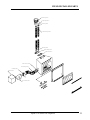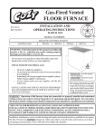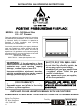
1
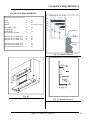
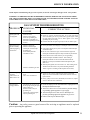
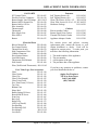
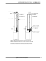
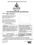
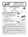
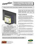
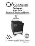
INSTALLATION AND OPERATING INSTRUCTIONS
LXi Series
POSITIVE PRESSURE GAS FIREPLACE
MODEL : LXi – NG Natural Gas
LXi – LP Propane
These gas appliances have been tested in accordance
with National Safety Standards, and have been certified
by Warnock Hersey for installation & operation as
described in these Installation and Operating
Instructions in the United States.
Check with your local building code agency before you
begin your installation to ensure compliance with local
codes, including the need for “permits” and follow-up
inspections. If any problems are encountered regarding
code approvals, or if you need clarification of any of the
instructions contained here, contact:
ALPINE GAS FIREPLACES
#801-768-8411 / www.alpinefireplaces. com
WARNING:
If the information in these
instructions are not followed exactly, a fire or
explosion may result causing property
damage , personal injury or loss of life.
Improper installation, adjustment, alteration,
service or maintenance can cause property
damage, personal injury or loss of life.
FOR YOUR SAFETY
Do not store or use gasoline or other
flammable vapors and liquids in the vicinity
of this or any other appliance.
WHAT TO DO IF YOU SMELL GAS:
Do not try to light any appliance.
Do not touch any electrical switch; do
not use any phone in your building.
• Immediately call your gas supplier from
a neighbor’s phone. Follow the gas
supplier’s instructions
• If you cannot reach your gas supplier,
call the fire department.
•
•
INSTALLATION AND SERVICE MUST
BE PERFORMED BY A QUALIFIED
INSTALLER, SERVICE AGENCY OR THE
GAS SUPPLIER.
INSTALLER: PLEASE LEAVE THIS MANUAL WITH THE CUSTOMER
HOMEOWNER: PLEASE KEEP THESE INSTRUCTIONS FOR FUTURE REFERENCE
Alpine Gas Fireplaces
782 West State Street
Lehi, Utah 84043
7/00
Tested by:
Alpine LXi Series Gas Fireplaces
ITS
1
TABLE OF CONTENTS
SAFETY INFORMATION
Safety Label .................................................. 3
Before Start ................................................... 4
General Safety Information........................... 4
System Specifications ................................... 5
SITE AND INSERT PREPARATION
Preparing the Fireplace ................................ 5
Preparing the Insert ....................................... 6
Blower and Duct Assembly .............. 6
Removing the Glass .......................... 7
Removing the
Appliance Adapter ............................ 7
Preparing the Leveling Bolts ............ 7
Routing Gas Piping To the Fireplace............ 7
Installing Chimney Liners............................. 8
Positioning the Insert .................................... 9
Trim Panel Installation ............................... 12
Fastening Face Pieces..................... 12
Control Panel Access
Door Installation............................. 12
Remote Control (Optional)............. 12
OPERATION & MAINTENANCE
Operating Guidelines.................................. 13
Appliance Maintenance.............................. 15
Replacing the Glass .................................... 17
Log Replacement........................................ 17
Normal Operating Sounds .......................... 17
Clearance Information................................ 18
Troubleshooting Guide............................... 19
Replacement Parts List ............................... 20
Supplemental Venting Information ............ 21
Field Installed Parts Diagram ..................... 22
INSTALLATION
Installing the Positive Pressure System ........ 9
Fan Cover Construction ................................ 9
Electrical Connections .................................. 10
Complete the Gas Connection ...................... 10
Installing Logs .............................................. 11
TESTING AND ADJUSTMENT
Test Unit and Adjust Controls ...................... 11
Primary Air Adjustment.................... 11
Pilot Light Adjustment...................... 11
Derating the Burner........................... 11
TRIM
Because masonry chimneys may crack due to settling,
Alpine LXi Series Gas Fireplaces
2
SAFETY INFORMATION
LABEL
Alpine LXi Series Gas Fireplaces
3
INSTALLATION REQUIREMENTS
IMPORTANT:
SAVE THESE INSTRUCTIONS
The LXi Series Direct Vent Fireplace must be installed
in accordance with these instructions. Carefully read all
the instructions in this manual first. Consult the
“authority having jurisdiction” to determine the need for
a permit prior to starting the installation. It is the
responsibility of the installer to ensure this fireplace is
installed in compliance with the manufacturer’s
instructions and all applicable codes.
This insert is intended to be installed by professional
installers that understand the principles of proper gas
installation techniques, venting principles, and safety
clearances. This manual is written with an assumption
that certain basic knowledge of this product exists with
the installer. The installation of this appliance should
not be attempted by anyone not familiar with these
basic principles.
BEFORE YOU START
NOTE TO BUILDING CODE OFFICIALS: The
principles of installation outlined in this manual are
representative of the majority of installations that
are encountered. There are several variations to
these instructions that could be acceptable. If a
variance to these instructions is encountered, we
recommend that you contact the manufacturer
directly to verify these variations.
Thoroughly review the needed clearances on page
17 of this manual before proceeding.
Safe installation and operation of this appliance
requires common sense, however, we are required by
ANSI Standards to make you aware of the following:
INSTALLATION AND REPAIR SHOULD BE
DONE BY A QUALIFIED SERVICE PERSON.
THE APPLIANCE SHOULD BE INSPECTED
BEFORE USE AND AT LEAST ANNUALLY BY A
PROFESSIONAL SERVICE PERSON. MORE
FREQUENT CLEANING MAY BE REQUIRED
DUE TO EXCESSIVE LINT FROM CARPETING,
BEDDING MATERIAL, ETC, IT IS IMPERATIVE
THAT CONTROL COMPARTMENTS, BURNERS
AND CIRCULATING AIR PASSAGEWAYS OF
THE APPLIANCE BE KEPT CLEAN.
DUE TO HIGH TEMPERATURES, THE
APPLIANCE SHOULD BE LOCATED OUT OF
TRAFFIC AND AWAY FROM FURNITURE AND
DRAPERIES.
WARNING: FAILURE TO INSTALL THIS
APPLIANCE CORRECTLY WILL VOID YOUR
WARRANTY AND MAY CAUSE A SERIOUS
HOUSE FIRE.
CHILDREN AND ADULTS SHOULD BE
ALERTED TO THE HAZARDS OF HIGH
SURFACE TEMPERATURES, ESPECIALLY
THE FIREPLACE GLASS, AND SHOULD STAY
AWAY TO AVOID BURNS OR CLOTHING
IGNITION.
YOUNG CHILDREN SHOULD BE CAREFULLY
SUPERVISED WHEN THEY ARE IN THE
SAME ROOM AS THE APPLIANCE.
CLOTHING OR OTHER FLAMMABLE
MATERIAL SHOULD NOT BE PLACED ON OR
NEAR THE APPLIANCE.
GENERAL SAFETY INFORMATION
1) The appliance installation must conform with
local codes or, in the absence of local codes, with
the current National Fuel Gas Code, ANSI
Z223.1 installation code.
2) The appliance when installed, must be electrically
grounded in accordance with local codes, or in
the absence of local codes with the current
National Electrical Code, ANSI/NFPA 70.
3) This appliance must be connected to the specified
vent and termination cap to the outside of the
building envelope. Never vent to another room or
inside a building. Make sure that the vent is fitted
as per venting instructions.
4) Inspect the venting system annually for blockage
and any signs of deterioration.
5) Any safety glass removed for servicing must be
replaced prior to operating the appliance.
6) To prevent injury, do not allow anyone who is
unfamiliar with the operation to use the fireplace.
7) Wear gloves and safety glasses for protection
while doing required maintenance.
8) Be aware of electrical wiring in locations in walls
and ceilings when cutting holes for termination.
9) Under no circumstances should this appliance be
modified. Parts that have been removed for
servicing should be replaced prior to operating
this appliance.
10) Installation and any repairs to this appliance
should be done by a qualified service person. A
professional service person should be called to
Alpine LXi Series Gas Fireplaces
4
INSTALLATION REQUIREMENTS
inspect this appliance annually. Make it a practice to
have all of your gas appliances checked annually.
11) Under no circumstances should any solid fuels
(wood, paper, cardboard, coal etc.) be used in this
appliance.
12) The appliance area must be kept clear and free of
combustible materials, gasoline and other flammable
vapors and liquids.
13) If the pilot goes out for any reason, turn the control
knob to the off position. Wait five minutes before
attempting to re-light pilot.
14) Never obstruct the flow of ventilation and
combustion air to the fireplace. Always be sure the
vent termination and air inlets remain clear and open.
Note: Output Capacity is a thermal efficiency rating
determined under continuous operating conditions and was
determined independently of any installed system. Vent
height may or may not change your efficiency ratings.
Min. Supply Pressure
Natural Gas
Propane
5.0” w.c.
11.0” w.c.
Max. Supply Pressure
Natural Gas
Propane
7.0” w.c.
13.0” w.c.
Manifold Pressure
Natural Gas
Propane
3.5” +/-0.2” w.c.
10” +/-0.2” w.c.
Minimum Gas Line Pipe Size: 1/2”
Electrical 120 VAC System
Amperage Rating: 3.25/3.50 Amps
Positive Pressure Fan: Variable Speed 495 CFM
The appliance and its individual shutoff valve
must be disconnected from the gas supply
piping system during any pressure testing of
that system when test pressures are in excess
of 1/2 psig. The appliance must be isolated
from the gas supply piping system by closing
its individual manual shutoff valve during any
pressure testing of the gas supply piping
system when test pressures are equal to or less
than 1/2 psig.
SYSTEM SPECIFICATIONS
(2500 To 6500 feet altitude)
NG
Burner Inlet Orifice Sizes:
LP
#00
#00
#00
#00
#00
#00
Max. Input Rating –
LXi – 270
LXi – 310
LXi – 360
00,000
00,000
00,000
00,000
00,000
00,000
Min. Input Rating –
LXi – 270
LXi – 310
LXi – 360
00,000
00,000
00,000
00,000
00,000
00,000
Fan Off Output –
LXi – 270
LXi – 310
LXi – 360
00,000
00,000
00,000
00,000
00,000
00,000
Fan On Maximum Output Capacity
LXi – 270
LXi – 310
LXi – 360
00,000
00,000
00,000
00,000
00,000
00,000
LXi – 270
LXi – 310
LXi – 360
chimney fires, water damage, etc. A thorough
inspection for this type of damage is strongly
encouraged. Any substantial damage must be repaired
previous to installation. The flue liners provided
should be adequate if damage is minor.
PREPARING EXISTING FIREPLACE
FOR INSERT INSTALLATION
1) When preparing an existing fireplace for an
Alpine insert, ensure that the clearances in this
manual are strictly adhered to.
2) Measure fireplace opening to ensure the
purchased product will fit.
3) Check fireplace dimensions on the installation site
before proceeding with installation. This will
ensure proper clearances and assist in identifying
potential problems before installation.
4) Review the vent termination and positive pressure
system requirements before proceeding with
installation.
MINIMUM FIREPLACE OPENING
Model
LXi-270
LXi-310
LXi-360
Width
27.5”
Height
20.5”
31.5”
36.5”
23 ”
25”
5) Ensure that the Positive Pressure Blower will be
accessible for post-installation maintenance.
6) Removal of firebrick may be necessary to obtain
the depth required for this type of installation.
7) A 7” hole must be made in the firebrick where the
air duct will pass through the wall at the point
where the blower will be mounted (see Fig 2).
Alpine LXi Series Gas Fireplaces
5
INSTALLATION REQUIREMENTS
Note: Do not damage any existing flue tiles that
may be to either side of the fireplace. Check the
venting routes of all other fireplaces or furnaces
in the chase area before actually beginning to cut
through for the positive pressure ducting.
PREPARING THE INSERT
Blower and Duct Assembly
Attach the flexible air duct (flex-duct ) that is
provided to the ducting connector (dovetail) by
applying a small bead of silicone to the inside of the
flex-duct about 1” back from the end and carefully
slide it over the crimped side of the dovetail. Wrap
Figure 2 – The Positive Pressure Hole
Figure 1-Preparing the Fireplace
8) The Positive Pressure Ducting may be brought
into the left or right side of the appliance. The
duct inlet is reversible. Be sure that the unused
side is sealed off completely to prevent loss of
Positive Pressure air.
9) If the Positive Pressure blower needs to be
mounted on the back of the chase, approximately
9” of open space behind the insert will be required
to accommodate the routing of the air ducting.
10) Before creating the hole, pilot a smaller hole
through the wall to determine the outside location
of the blower.
11) Ensure that the body of the appliance will fit into
the existing fireplace opening and that the existing
chimney can accommodate the two 3” liners
necessary for this insert (see page 7).
12) To determine if the two chimney liners will fit
through the existing damper, the damper must be
either bolted or clamped open. If the liners will
not fit through the damper, or has excessive
bends, it must be removed.
13) Plan gas piping and routing (see page 7).
14) Cut a 6” x 8” hole on the outside of the chase to
allow for proper installation of the blower adapter.
(see fig. 1)
the joint with duct tape to secure the flex-duct until
the silicone cures (See Figure 3). Lay the flex-duct
end with the dovetail in the approximate location that
the air hole on the fireplace will be once the insert is
positioned. This allows you to test fit the blower
assembly. Temporarily suspend the blower in this
location. Do not secure with fasteners at this point.
Removing the Glass
The decorative glass trim must be removed before
insert installation.
1) To remove the glass, remove the two trim hooks
inside the valve chamber. (see figure 4)
DUCTING
CONNECTOR
DUCT TAPE
FLEX-DUCT
Figure 3- Blower and Duct Assembly
Alpine LXi Series Gas Fireplaces
6
INSTALLATION REQUIREMENTS
2) Pull the bottom of the Trim forward about 4
inches.
3) Lift the trim up about ½ inch.
4) The trim should now be free and able to move
away from the appliance.
5) Take care to hold the glass in place, rapid
movements or rough handling will allow he glass
to fall out of the trim.
6) Set the trim aside so that it will not get damaged
during the installation process.
Slide Adapter to the Rear
Remove Attaching Screw
Removing the Appliance Adapter
The appliance may have been shipped with the
Appliance Adapter installed. Gently remove the
adapter by sliding it to the rear of the appliance. (See
Figure 5 -Removing the Appliance Adapter
fireplace.
Pull hook forward
and up to slot
on door bracket
ROUTING GAS PIPING TO
FIREPLACE
The LXi fireplace insert provides a gas piping inlet
hole on the front left side of the appliance. Gas piping
must be routed to this location prior to installing the
insert.
Determine where the fireplace will be positioned when
the installation is complete. Once this position is
determined,
gas line positioning can also be
determined. Ensure that the gas line and air duct do not
conflict.
Fig. 4– Removing the Trim Hooks
Note: Be sure not to damage the gasket on the glass.
figure 5). Take great care not to damage the white
adapter gasket. If the Gasket is damaged, do not install
the appliance until the gasket is replaced
Preparing the Leveling Bolts
The insert is equipped with two rear leveling bolts to
Note: Take special care not to damage the gasket
on the appliance adapter.
enable the fireplace to be easily leveled. These
leveling bolts need to be fully retracted prior to
inserting the appliance into the opening. This is done
to prevent damage to the existing fireplace hearth.
Once the appliance is located inside the fireplace
enclosure. The bolts may then be extended to level the
INSTALLING CHIMNEY LINERS
NOTE: Never connect this gas appliance to a
chimney or flue serving a separate solid-fuel
burning appliance.
The maximum vertical length of the venting system is
30’. The minimum vertical length of the venting
system is 8’. Horizontal termination of the vent is not
Note: Improper installation of gas piping is
potentially dangerous. All gas piping should be
installed by qualified individuals and strict
adherence to applicable codes is required. If you
are not familiar with gas piping or your local
codes, do not attempt to install the gas piping.
Alpine LXi Series Gas Fireplaces
7
VENTING REQUIREMENTS
approved.
Two 3” chimney liners (#09400) are used with Alpine
LXi series inserts. One liner will supply the
combustion air to the fireplace, the other will vent the
flue gases. Also required are:
• an appliance adapter which enables the liners to
be fastened to the insert (#00000)
• a co-linear adapter which enables the liners to be
joined with the termination cap (#09318)
• flashing to seal the flue tile
• a termination cap (#09317)
• two band clamps to fasten the liners to the
appliance adapter (#08530)
Exhaust Vent
Intake Vent
Band Clamp
Attach Fastening Screw
Slide Adapter in Gently
Installation Procedure
1) Measure the distance from the top of the flue tile
to the approximate top of the insert.
2) Add about 6” to your measurement and carefully
stretch each liner to that length.
3) Cut and bend the flashing to form a box type cap
to fit over the flue tile (the oval lip on the flashing
must be facing up).
4) Take the flashing and seal it to the flue tile with
some high quality sealant (remember the oval lip
on the flashing must be facing up to deter water).
NOTE: Be sure to identify each liner in the
fireplace so you can make proper connections. If
the insert is vented improperly, it will not function
and may create a dangerous situation.
5) Lower all but one foot of the vent liner through
the flashing into the flue tile.
6) Attach the liner to the co-linear adapter (see fig.
6).
7) Push the liner onto the nipple that flows through
the adapter until it seats against the gasket
material.
8) Fasten the liner to the adapter with 3-4 sheet metal
screws.
9) Lower the liner for combustion air and fasten it to
the co-linear adapter, in the same manner as the
Figure 7- Connecting the Appliance Adapter
vent liner, to the remaining nipple.
10) Lower the adapter onto the flashing and fasten
with sheet metal screws through the tabs provided.
Seal these screws with a high quality sealant to
prevent leaking. Seal around the adapter to
flashing joint.
11) Line up the lugs on the termination cap with the
receivers on the adapter and seat and then twist
the cap on.
12) Fasten the cap to the adapter with sheet metal
screws for added strength.
13) Slide the Exhaust Vent liner over the left outlet
on the appliance adapter. (See figure 7) Secure the
liner with one 3” band clamp.
14) Attach the Combustion Air liner to the remaining
nipple on the appliance adapter. Secure the liner
with one 3” band clamp.
15) Place the appliance adapter in its approximate
final position and, if needed, adjust the liners until
no severe bends or kinks exist. Be careful not to
tear or dent the liners or pull off one of the
Note: Take special care not to damage the gasket
material on the appliance adapter. An improper
seal will inhibit proper operation of the fireplace
insert.
T e r m in a t io n
C ap
C o - L in e a r
A d a p te r
Screw
C o m b u s t io n
A ir
E x h a u st
V ent
Figure 6 -Connecting the Co-linear Adapter
Note: Be sure to protect the hearth with
cardboard, thin plywood, or light sheet metal to
prevent the inset from marring , or scratching the
hearth.
Alpine LXi Series Gas Fireplaces
8
POSITIVE PRESSURE SYSTEM
connections. If a liner is punctured or torn, it must
be replaced.
See PAGE 21 for Supplemental Venting
Information.
WARNING: Failure to position the parts in
accordance with these diagrams or failure to use
only parts specifically approved with this appliance
may result in property damage or personal injury.
2)
POSITIONING THE INSERT
Gently place the insert on the hearth and route the
blower wires to the back of the insert through the
blower adapter hole. Gently slide the insert into
position. Use the leveling bolts provided to adjust the
height and the level of the insert. Final leveling is not
required at this point.
The adapter must be attached to the appliance while it
is being positioned. Make sure the adapter is properly
attached and secured before proceeding.
3)
INSTALLING THE POSITIVE
PRESSURE SYSTEM
6)
1) The air duct needs to be attached to the fireplace
insert. This is accomplished one of two ways. The
most common approach is, with the appliance in
its final location, attach the ducting through the
hole cut for the positive pressure system. A
dovetail adapter should be used to connect the
duct to the 6” hole on the side of the insert.
Another method is to connect the flexible ducting
7)
Note: The bottom trim panel will need to be
installed to adjust the height. See “Trim Panel
Installation”.
See page 22 for a Diagram of field installed parts.
4)
5)
to the appliance before it is placed back into the
fireplace opening and then gently push the duct
into position as the fireplace is placed into its
operating location.
Reach in through the blower adapter hole and
gently pull out any excess flex-duct. Cut the flexduct leaving about 8” protruding past the exterior
of the home. If the chase is brick, 1/4” holes must
be marked and drilled into the brick, about 1&1/2”
in depth, and insert the fluted anchors provided
(see figure 8).
Apply a small bead of silicone to the inside of the
flex-duct about 1” back from the end.
Carefully slide the flex-duct over the blower
adapter, being careful not to tear the flex-duct,
leaving about 3/4” exposed metal so that the joint
may be wrapped with duct tape to secure the flexduct until the silicone cures.
Insert the black nylon grommet (provided) into the
smaller hole on the blower adapter and gently feed
the high temperature wires to the fireplace through
it.
Mount the blower adapter to the exterior wall of
the chase using the 1-1/4” screws provided (If
desired, a seal between the adapter and the
exterior wall may be made with silicone).
Mount the blower motor to the blower adapter
with the four 1/4” hex head screws provided,
keeping the motor portion of the blower on the
same side as the wire holes in the blower adapter.
FAN COVER CONSTRUCTION
The fan cover box is easily constructed from the
provided three-panel kit (For more exhaustive details,
see instructions included with the kit).
Procedure
1) Place panel 1 on a flat surface with its 1/2” top
flange sticking up and its 3/4” bottom flange
sticking down.
2) Gently bend flaps A and C of panel 1 until they
are perpendicular to flap B and parallel to each
other (See fig. 9).
Alpine LXi Series Gas Fireplaces
9
ELECTRICAL/GAS REQUIREMENTS
Figures 10 – Fan Box Completion
Figure 8 -Mounting the Blower System
3) Place panel 2 over the unattached ends of flaps A
and B of panel #1 (See fig. 10).
4) Insert and tighten 4 of the provided screws.
5) Place panel 3 on top of the newly created box (See
fig 11)
6) Insert and tighten the four remaining screws.
also
the
itself. These
connected
end to end.
w i r e s
the fireplace
One
wire
blower motor
switches are
in series or
The other two
coming from
a
r
e
indiscriminate.
must
be
Figures 11 – Fan Box Completion
NOTE: The intake grill on the fan box should be
facing either down or to the side. It should never
face up.
connected to the fan and the other must be connected
to either leg of the 120 lead, leaving the remaining
wire from the fireplace and the remaining 120 power
lead to be connected to each other (see figure 12).
ELECTRICAL CONNECTIONS
The simplest and most effective way to get power to
the system is to run a 120V A.C. line to the fan
location. The 120V A.C. power runs through the
fireplace in a series loop. The power runs through the
fan control switch, the thermostatic on/off switch, and
FLAP A
FLAP C
FLAP B
GAS CONNECTIONS
1) Install the final gas nipple into the fireplace insert
(the nipple should only extend about 3” past the
interior wall of the fireplace insert).
2) Connect the appliance gas shut off valve and
Note: Be sure the power is off to avoid electrical
shock.
Figure 9– Fan Box Cover Creation
proceed to check for leaks (consult local building
officials for the accepted test procedure in your
area).
3) After testing the system for leaks, install the
Alpine LXi Series Gas Fireplaces
10
ELECTRICAL/GAS REQUIREMENTS
ALPINE FIREPLACE
WIRING SCHEMATIC
18 AWG, CLASS B-1, 32MM INSUL.
BLK
BLK
THERMAL
FAN
SWITCH
18AWG, CLASS B-1
TAN/BLK
BLK
TAN/WHT
18AWG, CLASS B-1
BLK
BLOWER
CONTROLLER
size of the insert. The 360 model has three top logs
while both the 270 and 310 models have two top logs.
The top logs should be placed perpendicular to the
front and back logs and should never be placed in a
manner to restrict the flame from coming up between
the front and back logs.
UNIT TESTING AND CONTROL
ADJUSTMENTS
BLOWER
AERATION ADJUSTMENT
BLK
LINE IN
WHT
14/2 SHEATHED CABLE
(CUSTOMER SUPPLIES)
Figure 12-Electrical Schematic
NOTE: The appliance and its individual shut off
valve must be disconnected from the gas supply
piping system during any pressure testing of that
system in excess of 1/2 psig.
The appliance must be isolated from the gas
supply piping system by closing its individual
manual shut off valve during any pressure testing
of the gas supply piping system when test
pressures are equal to or less than 1/2 psig.
NOTE: The following assumes that the gas line has
been connected and leak tested by a qualified
technician.
The primary air adjustment is preset at the factory.
Little or no adjustment may be required for natural
gas. Propane will perform very differently at different
altitudes and from different fuel suppliers. Some
adjustment will most likely be needed for an appliance
Note: A flame hitting directly on the bottom of a
log will burn dirty and cause excessive soot build
up on the log and inside the firebox.
connect the flexible appliance adapter to the gas
line.
4) Turn the gas supply on to the fireplace and test
again for gas leaks.
Figure13 -Log Installation
LOG INSTALLATION
Gently remove the logs from their packaging.
Place the two largest logs on the locating pins on the
burner (the bigger of the two placed in the front and
the smaller placed to the rear). The face of the back
log should be even with the back of the burner,
centered, and then gently pushed down onto the
locating pin. The face of the front log should be
behind the front of the burner approximately 1/2 of an
inch and centered.
The number of top logs will vary depending on the
burning propane.
The flame should have a blue base with yellow tips. A
dark orange flame with sooting and black smoke
indicates a lack of primary air. The primary air shutter
is located in the firebox on the right hand side of the
burner. Adjust the primary mixture by loosening the
set screw on the air shutter and increasing the opening
for more air and a bluer / cleaner flame, or by closing
the air shutter for a more yellow flame. See figures 14
and 15 for proper flame characteristics.
Pilot Light Adjustment
The pilot light is preset at the factory and should
require no adjustment. The flame on the pilot should
project about 5/8” past the pilot head, with enough
Alpine LXi Series Gas Fireplaces
11
ELECTRICAL/GAS REQUIREMENTS
flame to impinge on both the thermocouple on the left
side and the thermopile on the right side of the pilot
head. If the pilot is erratic, noisy, or yellow, call your
Alpine Fireplaces Dealer or another qualified service
technician to make the adjustment.
DERATING THE BURNER
The fireplace has been designed to operate at
Venturi
Venturi Set Screw
the edge of the top piece. Line up the right side piece
with the bottom piece. Secure the right side piece.
5. Repeat step #4 on the left side.
6. With all pieces lined up and even, secure all screws.
7. See Figure 16 for an exploded view of the face
pieces and their proper locations .
8. With the screws tightened, test fit the glass panel to
make sure it will fit within the opening. Adjust the
panels if needed.
9. The top louver set may now be attached with four
bullet catches, two on each end.
10. The bottom louver set comes with the hinges
attached. Attach the hinges to the appliance and test
the louver set for proper function.
Control Panel Access Door Installation
Figure 14- Adjusting the Primary Air Mixer
YELLOW TIPS
BLUE FLAME
1) Place two hinges on the access door in the open
position.
2) Lay the door on the fireplace with the hinge
mounting holes positioned over the two mounting
holes located on each side of the fireplace.
3) Secure with the four #8 self-tapping screws
provided.
REMOTE CONTROL (Optional)
An Alpine Remote Control Kit (08501) may be
Note: Subsequent pilot ignitions should not require
the removal of the glass.
BURNER BASE
Figure 15- Proper Flame Characteristics
elevations approximately 4500 ft. above sea level. No
deration of the burner needs to occur unless the
fireplace is installed at elevations below 2500 ft. or
above 6500 ft. The burner orifice should then be
adjusted one drill size smaller for higher elevations
and one drill size larger for lower elevations.
TRIM AND DOOR INSTALLATION
Attach all trim panels before snugly tightening all of
the screws. This will provide you with the ability to
make all joints uniform.
1. Attach the bottom trim piece with the screws
provided.
2. Attach the top trim panel
3. Attach the left and right side panels
4. Line up the outside edge of the right side piece with
Figure 16– Face Trim Installation
Alpine LXi Series Gas Fireplaces
12
OPERATING INSTRUCTIONS
on
pilot
off
To thermopile
RED
WALL
THERMOSTAT
(M ILLIVOLT)
(O PTIONAL)
6)
7)
8)
9)
instructions on what to do if you smell gas. If you
don’t smell gas then go to the next step.
Turn gas control knob counter clockwise to the
“pilot” position.
Depress gas control knob completely and hold.
Push in red igniter button just to the left of the
valve until an audible click is heard. This creates
the spark to light the pilot. The igniter may need
to be pushed several times before the pilot lights.
Once the pilot is lit, continue to hold the control
knob in for 60 seconds. Release the knob and it
should pop back out to it’s original position. The
pilot should remain lit. If pilot goes out repeat
steps 3 through 7.
If the glass has been removed for initial start up of
the appliance, it must be replaced before igniting
the main burner.
Turn the gas control knob counter clockwise to
the “on” position.
Note: There may be air in the gas line that needs
to be purged out when first lighting the appliance.
Note: If the pilot will not stay lit after several
tries, turn the gas control knob to the “off” position and call your Alpine dealer, your gas supplier, or another qualified service technician.
10) Place the “on/off” switch in the “on” position (the
fireplace should light immediately).
Note: On cold start up of the fireplace the pilot
should be allowed to run for at least five minutes
to start a draw, and to allow the thermopile time
to heat up before turning the fireplace on.
11) Flame height may be varied by the HI-LO knob
on the gas valve. Turning the knob counter
clockwise will increase the flame height and
TP TH
TP
HI
LO
To wall switch,
remote control
or thermostat
TH
PILOT
RED
REMOTE
refer to the cover page of this manual for
RED
Fig. 18– Millivolt Schematic Wiring
OPERATING GUIDELINES
The millivolt system has limitations on the distance it
can be installed from the fireplace. The greater the
distance from the fireplace, the larger the wire size
must be to prevent loss of the millivoltage. See the
table below for recommendations.
Maximum Length
Wire
Guage
9’
22 ga.
13’
20 ga.
20’
18 ga.
30’
16 ga.
WHITE
WHITE
BROWN
REMOTE
RECEIVER
(DC/
MILLIVOLT)
(O PTIONAL)
Wall Thermostat (Optional)
1) Make sure the on/off switch is in the off position.
2) Make sure gas supply is on, and shut off valves
are open.
3) Push in gas control knob slightly and turn
clockwise to the “off” position.
4) Remove glass for initial startup.
5) Wait five minutes for any gas which may be
present in the combustion area to escape. If you
then smell gas stop the lighting procedure and
A
WALL
SWITCH
(M ILLIVOLT)
BURNER
ON/O FF
ON
3. Follow the installation instructions included with the
remote control kit.
IGNITOR
BUTTON
(PIEZO)
HI
E
LO
"S.I.T."CONTROL
VALVE
1. Choose a convenient location on the wall to install
the receiver unit. A standard electrical box may be
used. Run wires from the fireplace valve to the desired
wall location. See the millivolt lead table below for
maximum wire runs.
2. Connect the wires to the gas valve (see figure 17 &
18).
Thermocouple
in located
on back of
control
valve
gas
inlet
OFF
installed on this fireplace. The remote control kit
comes with a hand held transmitter, and a receiver.
The remote control is thermostatically controlled so
you can set the fireplace to the desired room
temperature, and have that temperature maintained.
The remote control is battery powered and will require
periodic maintenance to keep the system working
properly.
Figure 17 – Gas Valve Connections
Alpine LXi Series Gas Fireplaces
13
OPERATING INSTRUCTIONS
FOR YOUR SAFETY READ BEFORE LIGHTING
This appliance must be installed in accordance with local codes, if any;
If not, follow the current ANSI Z223.1
WARNING: If you do not follow these instructions exactly, a fire or
explosion may result causing property damage, personal injury or loss of
life. Improper installation, adjustment, alteration, service or maintenance
can cause injury or property damage. Refer to the owner’s information
manual provided with this appliance. For assistance or additional
information consult a qualified installer, service agency or gas supplier.
A) This appliance has a pilot which must
be lighted by hand. When lighting the
pilot, follow these instructions exactly.
B) BEFORE LIGHTING smell all around
the appliance area for gas. Be sure to
smell next to the floor because some
gas is heavier than air and will settle
on the floor.
WHAT TO DO IF YOU SMELL GAS
−
−
Do not try to light any appliance
Do not touch any electrical switch, do
not use any phone in your building.
−
Immediately call your gas supplier from
a neighbors phone. Follow the gas
suppliers instructions.
−
If you cannot reach your gas supplier,
call the fire department.
C) Use only your hand to push in or
turn the gas control knob. Never use
tools. If the knob will not push in or
turn hand, don’t try to repair it, call
a qualified service technician. Force
or attempted repair may result in a
fire or explosion.
D) Do not use this appliance if any part
has been under water. Immediately
call a qualified service technician to
inspect the appliance and to replace
any part of the control system and
any gas control which has been
under water.
This appliance needs fresh air for safe
operation and must be installed so there are
provisions for adequate combustion and
ventilation air.
CAUTION: Hot while in operation. Do not touch. Keep children, clothing,
furniture, gasoline and other liquids having flammable vapors away. Keep
burner and control compartment clean. See installation and operating
instructions accompanying appliance.
LIGHTING INSTRUCTIONS
STOP! Read the safety information above on
this label.
1) Push in gas control knob slightly and turn
clockwise C to “OFF”. Knob cannot be
turned from “PILOT” to “OFF” unless
knob is pushed in slightly. Do not force.
2) Wait five (5) minutes to clear out any gas.
If you then smell gas STOP! Follow “B”
in the safety information above on this
label. If you don’t smell gas, go to the next
step.
3) Turn knob on the gas control
Pilot Burner
THERMOPILE
Clockwise to “OFF”
C
4) Push in control knob all the way and hold
in. Continually push and release the red
button on the spark ignitor until pilot
lights. Continue to hold the control knob
in for about 1/2 minute after the pilot is
lit. Release knob and it will pop back up.
Pilot should remain lit. If it goes out,
repeat steps 1 to 4. If knob does not pop
up when released, stop and immediately
call your service technician or gas
supplier. If the pilot will not stay lit after
several tries, turn the gas control knob to
“OFF” and call your service technician or
gas supplier.
5) Turn gas control knob counterclockwise
D to “ON”
6) Use the toggle switch to operate main
burner.
TO TURN OFF GAS APPLIANCE
1) Push in the gas control knob slightly and
turn clockwise C to “OFF”. Do not force.
2) Turn off all electric power to the appliance
if service is to be performed.
DO NOT REMOVE THIS INSTRUCTION PLATE
Alpine LXi Series Gas Fireplaces
DVI-700-1
14
SERVICE INFORMATION
12)
13)
14)
15)
turning it clockwise will decrease the flame
height.
The fan control switch will vary the speed of the
fan or turn the fan off. The fan is also turned on
and off by a thermally activated switch built into
the firebox. This will prevent the fan from
blowing cold air into the home. There are many
flame height and fan speed variations which may
be adjusted to meet an individual comfort level.
In the event of a power outage, your Alpine
fireplace my still be used as a source of radiant
heat. However, the fireplace is most effective and
efficient with the fan running.
To turn the fireplace off , simply pull down the
control panel access door and turn the on/off
switch to the off position. The fan will turn itself
off after the fireplace has sufficiently cooled
down. It is not necessary to turn the fan control
switch off.
For complete shut down of the appliance,
including the pilot, simply depress the control
knob on the gas valve, and rotate clockwise to the
“off” position.
FIREPLACE MAINTENANCE
1) Before performing any service on the appliance,
ensure the gas has been completely shut off, the unit
cooled, and the electricity shut off to the appliance.
2) The burner and valve control compartments must
be cleaned annually. A vacuum with a brush
attachment works well. The logs should be cleaned
gently with a soft bristle brush. The logs are fragile
and are easily damaged.
3) Clean the appliance with a damp cloth. Never use
abrasive cleaners. The glass should be cleaned with
a gas fireplace glass cleaner. The glass will slowly
build a thin white film on the inside. This film is
normal and can be removed using a fireplace glass
cleaner available at your local dealer.
4) The fireplace is finished with a high temperature
Note: During the first hours of operation there
may be a slight odor omitted from the fireplace
due to the curing and burning of the paints, and
construction lubricants.
Note: Every time the appliance is started, while
cold, condensation will occur on the inside of the
glass panel. This condensation will clear as the
appliance heats up.
Paint.
5) The appliance and the venting system must be
inspected before use, and at least annually, by a
qualified field technician. The vent must be
inspected to ensure that the flow of combustion air
and ventilation air is not obstructed.
6) Do not use this appliance if any part has been under
water. Immediately call a qualified service
technician to inspect the appliance and to replace
any part of the control system and any gas control
which have been under water.
Note: It is also highly recommended to apply the
glass cleaner to the inside of the glass before the
first burn.
CAUTION: DO NOT USE OVEN CLEANER TO
CLEAN THE GLASS
7) If the venting system is disassembled for any reason
it must be properly resealed as per the instructions
in the venting section of this manual. Never operate
the appliance if the venting system is not properly
sealed.
8) The optional blower system requires annual
lubrication. The blower is marked with lubrication
points. Use a good quality light machine oil for
lubrication. Apply three drops per port annually.
GOLD or BRASS TRIMS
The gold plate or brass trims on the fireplace require
little maintenance. If the pieces get fingerprints or dust
build-up, you should use a damp cloth only for
cleaning. DO NOT use cleaners of any type on the
brass or gold. Be sure to clean any fingerprints off of
the unit BEFORE turning the fireplace on.
REMOVING VALVE
1) Open the bottom valve door
2) Shut off the gas supply
3) Disconnect the inlet gas line (3/4” wrench)
4) Disconnect the 2 TP wires from the valve
5) Disconnect the 2 TH wires from the valve
6) Disconnect the pilot tube from the valve (use a
7/16” wrench)
7) Disconnect the thermocouple from the valve (use
9mm wrench)
8) Disconnect the main burner tube (11/16” wrench)
9) Remove the 2 square nuts securing the valve holder
to the floor
Remove the valve from the appliance
paint. If your fireplace needs to be repainted or
touched up. See your local dealer for StoveBright
Alpine LXi Series Gas Fireplaces
15
SERVICE INFORMATION
GLASS GASKET
INSTALLING VALVE
1) Mount valve to valve holder
2) Place valve / valve holder back into position
3) Secure valve with 2 square nuts
4) Connect main burner gas tube (use 11/16”
wrench)
5) Connect the thermocouple to the valve (use a
9mm wrench)
6) Connect the pilot tube to the valve (use 7/16”
wrench)
7) Connect the TH wires to the valve
8) Connect the TP wires to the valve
9) Connect the main gas supply to the valve (use a
3/4” wrench)
10)Double check to make sure all connection are
complete and tight
11)Restore gas supply
12)Using a soap solution, check for leaks in main gas
supply.
13)Make sure the toggle switch is in the “OFF”
CAUTION: Never use an open flame to check for gas
leaks. Always use a soap solution to check for leaks.
Position
14)Ignite pilot and check for leaks in pilot line
15)Ignite main burner and check for leaks in main
burner tube.
If the glass gasket needs to be replaced, use a 3/8”
tadpole gasket. contact your local dealer for the correct
replacement part. Never attempt to use any gasket, other
than the correct replacement on the glass. Use part #
07840.
GLASS PANEL
WARNING: Do not slam the door or strike the
ceramic panel with a heavy or hard object. Breakage
of the panel will result.
WARNING: Do not operate the appliance with the
glass front
removed, cracked, or broken.
Replacement of the glass panel should be done by a
qualified service technician.
Your fireplace is supplied with a pane of high
temperature 5mm neoceram glass panel that is capable of
withstanding the highest heat that your fireplace can
produce. Never attempt to use another type of glass or
other material. If your glass requires cleaning, you should
obtain an approved fireplace glass cleaner available at
your fireplace dealer. Do not use abrasive cleaners to
clean the glass panel. DO NOT CLEAN THE GLASS
WHEN IT IS HOT!
In the event that you break your glass by impact,
purchase your replacement from an authorized Alpine
dealer. See the replacement parts list for ordering
information. Follow the replacement steps below.
Replacing the Glass
1) Remove the door by releasing the glass clip springs
found in the valve chamber area.
2) Always where gloves to protect yourself from sharp
edges.
3) Remove all loose or damaged glass from the frame.
4) Insert the new glass panel with the gasket preinstalled
5) Use the 6 existing Tinnerman glass clips to hold the
glass in place.
6) It is imperative that the glass be spaced in the frame so
that it is lightly resting within the door frame.
Glass with Gasket
Glass Clip
Alpine LXi Series Gas Fireplaces
16
SERVICE INFORMATION
THERMOPILE / THERMOCOUPLE
1) Remove the glass door
2) Open the bottom valve chamber
3) Double check to make sure gas supply is turned off
4) Disconnect the thermocouple by loosening nut from
the valve with a 9mm wrench. Disconnect the
thermopile by loosening 2 screws marked TP on the
valve.
5) Remove the two 1/4” screws holding the pilot
assembly in its bracket. Gently lift the pilot assembly
up 2”.
6) Disconnect the thermopile and thermocouple with a
7/16” wrench.
7) Replace the thermocouple or thermopile.
8) Reinstall in reverse order.
LOG REPLACEMENT
The fireplace must never be operated if the logs are
broken or damaged. To replace the logs follow the steps
below.
1) Turn off the gas supply and allow the fireplace to cool
completely before servicing.
2) Open the glass door panel.
3) Gently remove the logs from the firebox. Be sure to
note their position.
4) Obtain the proper replacement for the broken log.
5) Replace the log set and close the door panel.
NOTE: It is critical that the logs are placed in the
proper locations. Improper positioning of logs may
create carbon build-up and will severely alter the
unit’s performance. Poor appliance performance
caused by improper log installation is not covered
under warranty.
INSPECTING THE PILOT / BURNER
Periodic inspection of the pilot and main burner is
required. Figure 15, located on page 11 of this manual,
illustrates proper flame characteristics for the main
burner. See figure 19 below for proper pilot flame
characteristics.
Pilot
Flame should
engulf the top
3/8" to 1/2"
Thermopile
Quick Drop out
Thermocouple
Fig. 19– Pilot Flame Characteristics
NORMAL OPERATING SOUNDS OF
GAS APPPLIANCES
It is possible that you will hear sounds during the
operation of your gas fireplace insert. These sounds
are perfectly normal and should not be considered
defects in your appliance.
Blower:
Alpine uses a State of the Art blower to push the
heated air throughout your home. It is not unusual
for the fan to make a rushing air sound when it is on.
This sound will increase and decrease in volume
depending on the speed of setting of your blower
controller.
Metal Firebox:
The firebox is made of a high quality steel. Steel, by
its very nature, expands and contracts as it heats and
cools. You will often hear a “ticking” or “clicking”
sounds as the appliance heats and cools. Again, this
is normal for steel fireboxes.
Pilot Flame:
While the pilot flame is on it can make a slight hissing sound. This is also normal
Gas Control Valve:
As the gas control turns ON and OFF, a click sound
may be audible. This is the normal operating sound
of a gas valve.
Alpine LXi Series Gas Fireplaces
17
CLEARANCE REQUIREMENTS
CLEARANCE REQUIREMENTS
12 10 8
Clearances From Unit (See fig 20)
6
4
2
0
23
Sides
Ceiling
Mantel
A
B
C
00”
00”
See Figure 21 & 22
Max. Mantle Width
Hearth Height
Hearth Depth
Minimum Hearth Width
D
E
F
G
12”
0”
16”
Minimum Alcove Width (270)
Minimum Alcove Width (310)
Minimum Alcove Width (360)
H
H
H
00”
00”
00”
Maximum Alcove Depth (270)
Maximum Alcove Depth (310)
Maximum Alcove Depth (360)
I
I
I
00”
00”
00”
18
12" mantel
16
8" mantel
14
3-1/2"
mantel
12
10
faceplate top
top of
fireplace
side view of
fireplace
Fig. 21– Mantel Clearance
Fig. 20–
Fig. 22– Hearth Clearances
Alpine LXi Series Gas Fireplaces
18
SERVICE INFORMATION
NOTE: Before troubleshooting the gas control system, be sure the external gas shut off is in the “ON” position.
WARNING: TO PREVENT INJURY OR PROPERTY DAMAGE, REMOVE THE GLASS PANEL FROM
THE APPLIANCE BEFORE DOING ANY WORK ON THE GAS CONTROL SYSTEM. FAILURE TO DO SO
COULD RESULT IN GAS BUILD-UP AND EXPLOSION.
GAS SYSTEM TROUBLESHOOTING
PROBLEM
POTENTIAL
CAUSES
Spark igniter will
not light pilot.
Piezo wire loose
Defective Piezo ignitor
Piezo wire grounding out
Electrode is grounding out
Electrode is sparking at wrong
location
•
Check for spark at electrode and pilot. If no spark, disconnect
wire at electrode, put wire to ground, and try igniter again. If still
no spark follow the Piezo wire to Piezo igniter to see where
grounding may be occurring.
•
Position electrode into pilot so gas may be able to contact spark
Defective thermopile
Defective thermocouple
Thermopile / thermocouple
grounding out.
Loose thermopile leads
TP-THTP on valve
•
•
Check pilot flame, must impinge on thermopile and thermocouple
•
Be sure wire connections at gas valve terminals are tight and
thermopile and thermocouple are fully inserted into pilot bracket
Pilot will not stay
lit after carefully
following lighting
instructions
CORRECTIVE ACTION
•
•
•
Defective automatic gas valve
Pilot burning, no gas
to burner.
Valve knob is on
Wall switch is on
Valve wire connections are
loose
Valve wires are defective
Frequent pilot
outage problems
Pilot flame may be too low or
blowing high causing the pilot
safety to drop out
Wall switch wires may be
grounding out.
Thermopile or thermocouple
may be grounding out.
Clean and/or adjust pilot so pilot is enveloped around thermopile
and thermocouple.
Check switch wires to make sure they are not grounding
Check thermopile with millivolt meter. Take reading at
thermopile terminals of valve TP-TPTH. Should read 325
millivolts (circuit open) minimum while thermopile has pilot
flame on it.
With the pilot ignited, turn valve knob to on. Take reading at TPTPTH with on/off switch in on position. Reading should be
100mv or greater. If reading is OK and pilot does not hold,
•
Check two way switch / wall switch for proper connections.
Jumper wire across terminals at wall switch. If burner comes on,
replace switch.
•
If okay, jumper wire at valve (TH-THTP). If unit turns on, replace
wires or check for loose connections
• Clean and adjust pilot for maximum flame impingement on
•
•
•
thermopile and thermocouple.
Trace wires from valve to wall switch for possible damage
or grounding against appliance or gas supply.
Trace thermopile wires from valve to thermopile for
possible grounding against the appliance or gas valve.
Follow same steps for thermocouple
Caution:
Any safety screen or guard removed for servicing an appliance must be replaced
prior to operating the appliance
Alpine LXi Series Gas Fireplaces
19
REPLACEMENT PARTS INFORMATION
GAS PARTS
SIT Control Valve
Flexible Gas Line Connector
Burner Supply Line W/Fittings
Burner Orifice-Natural Gas
Burner Orifice-LP Gas
Pilot Assembly
Thermocouple
Thermopile
Pilot Supply Line
Pilot Orifice
Burner
DV-01-005
DV-01-010
DV-01-015
DV-01-020
DV-01-025
DV-01-030
DV-01-035
DV-01-040
DV-01-045
DV-01-050
DV-01-055
Electrical Parts
Blower Motor/Fan
Fan Control Switch
Thermal Fan Switch
High Temperature Wire
Conduit Connector
Piezo Ignitor Button
Overlimit Sensor
Thermostat (Wall Mount)
Wall Switch
Wire (Wall Switch/Thermostat)
DV-02-060
DV-02-065
DV-02-070
DV-02-075
DV-02-080
DV-02-085
DV-02-090
DV-02-095
DV-02-100
DV-02-105
Face Trim, Logs, Fan Accessories
Glass
DV-03-110
Glass Gasket
DV-03-115
Glass Clip
DV-03-120
Glass Trim (Painted)
DV-03-125
Glass Trim (Gold)
DV-03-130
Face Trim Frame (3 Pieces)
DV-03-135
Top Gate
DV-03-140
Bottom Gate
DV-03-145
Hinge Rod
DV-03-150
Return Spring W/Screw
DV-03-155
Brass Knob W/Screw
DV-03-160
Front Log
DV-03-165
Back Log
DV-03-170
Right Twig
DV-03-175
Left Twig (Small)
DV-03-180
Fan Housing
DV-03-185
Fan Housing Grill
DV-03-190
Fan Adapter
DV-03-195
Lava Rock
DV-03-200
Fasteners
Self Tapping Screws-#8
Self Tapping Screws-#10
Glass Clip Screws-10-24 x 1/2
Glass Trim Screws-10-24 x 1-1/2
Hardware Package
DV-04-210
DV-04-215
DV-04-220
DV-04-225
DV-04-230
Gaskets
Pilot Assembly Gasket
Burner Supply Line Gasket
Thermal Fan Switch Gasket
Appliance Adapter Gasket
DV-05-235
DV-05-240
DV-05-245
DV-05-250
For current prices and policies covering
replacement parts, contact the factory or your
Alpine distributor or dealer. Parts will be
supplied at current prices. To order parts, you
must have the following information:
1.
2.
3.
4.
The model number of the appliance.
The part number.
A description of the part.
The purchase date of the appliance.
If you have any questions or problems, contact
your local distributor/dealer or:
Alpine LXi Series Gas Fireplaces
Alpine Gas Fireplaces
782 West State Street
Lehi, Utah 84043
(801) 768-8411
20
SUPPLEMENTAL VENTING INFORMATION
Termination Cap
Adaptor
This option shows the
Air Intake Pipe
connected to the Intake
Collar and terminated at
the termination cap.
This option shows the
Air Intake Pipe
connected to the Intake
Collar and terminated 4'
inside the chimney
Exhaust Vent Pipe
Air Intake Pipe
Warning: Do not block
pipe end with insulation
or any other material
Air Intake Pipe
Insulation required here
to create air tight seal
WARNING: THE EXHAUST PIPE MUST ONLY BE CONNECTED TO THE
EXHAUST COLLAR ON THE FIREPLACE AND THE CENTER COLLAR OF THE
TERMINATION CAP.
THE INTAKE AIR PIPE MUST ONLY BE CONNECTED TO THE INTAKE AIR
COLLAR ON THE FIREPLACE AND EITHER ATTACHED TO THE INTAKE AIR
COLLAR OF THE TERMINATION CAP OR TERMINATED IN THE CHIMNEY.
Alpine LXi Series Gas Fireplaces
21
FIELD INSTALLED PARTS
Termination Cap (#09317)
Venting Adapter (#09318)
Band Clamp (#08530)
3" Aluminum Venting (#09400)
Band Clamp (#08530)
Appliance Adapter (#29700)
Adapter Gasket (#29701)
Dovetail Connector (#04021)
Flexible Ducting (#04018)
Fan Adapter (#04023)
Fan Box (#04005)
495 CFM Blower (#08215)
Alpine LXi Series Gas Fireplaces
22