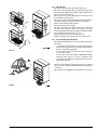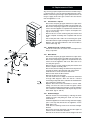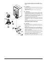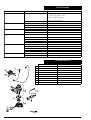
1
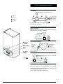
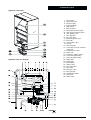
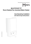
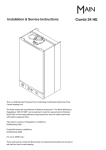
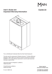
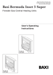
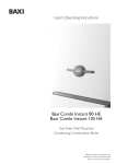
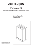
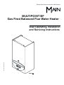
Please leave these instructions with the user
MULTIPOINT BF
Gas Fired Balanced Flue Water Heater
6 720 607 090 (03.12) JS
User Operating, Installation
and Servicing Instructions
Natural Gas
Main Multipoint BF
G.C. No 52-467-01
This appliance conforms to European Standard EN 26.
Type test for purpose certified by Notified Body CE-0087.
Product/Production certified by Notified Body CE-0464.
For GB / IE only.
Care must be taken when lifting and handling this appliance,
seek assistance where appropriate. Protective equipement
(e.g. gloves) should be worn as necessary.
User Information
Your Main Multipoint BF is designed to meet all relevant
standards.
Main provide a 12 month guarantee on the appliance. The
guarantee operates from the date installation is completed
for the customer who is the original owner.
Any component or part which becomes defective during the
guarantee period as a result of faulty workmanship or
materials whilst in normal use will be repaired or replaced
free of charge.
2
6 720 607 090
Contents
Section
1.
2.
3.
4.
5.
6.
7.
8.
9.
10.
11.
12.
13.
14.
15.
16.
6 720 607 090
page
User’s Operating Instructions ..................................... 4
General Layout .............................................................. 5
Technical Data ............................................................... 6
Dimensions and Fixings ................................................ 7
General Information ...................................................... 8
Installation Regulations ................................................ 8
Siting the Appliance ..................................................... 9
Siting the Flue Terminal ............................................ 10
Air Supply ..................................................................... 11
Gas Supply .................................................................. 11
Installation .................................................................... 11
Commissioning ............................................................ 13
Inspection and Servicing .......................................... 14
Replacement of Parts ................................................ 16
Fault Finding ................................................................ 18
Short Parts List ........................................................... 18
3
1. User’s Operating Instructions
Pilot ignition:
1. Depress slide control and hold it in.
- Off
2. Press the
igniter repeatedly until the
pilot is alight.
- Pilot
- Burner
- Igniter
3. Release the slide control approx 10
seconds after pilot lights.
4. Repeat these steps if the pilot does not remain alight.
Burner operation:
When the slide control is in the “burner” position the burner
will ignite when a hot tap is turned on.
Temperature regulation:
Turn left
to reduce
water
temperature
Turn right to
increase
water
temperature
Note: with higher temperatures the available flow of water
will be reduced.
Switching off:
Move slide control to the far left
Note: the pilot flame will extinguish
Note: if the appliance is to be left unused in an unheated
area during cold weather the gas and water supplies should
be isolated and the system drained.
Your installer will be able to advise you.
4
6 720 607 090
2. General Layout
Appliance components
1
2
3
4
5
6
7a
7b
8
9
10
11
12
13
14
15
16
17
18
19
20
21
22
23
24
25
26
27
28
29
30
31
32
Fig. 3
Appliance water flow diagram.
Pilot burner
Spark electrode
Thermocouple
Heat exchanger
Main burner
Burner injector
Burner pressure test point
Inlet gas pressure test point
Gas setting screw
Pilot gas filter
Pilot gas valve
Electromagnetic valve
Gas filter
Slow ignition valve
Venturi
Gas inlet pipe
Correcting screw for minimum
water flow
Temperature control
Drain cock
Volumetric water governor
Cold water pipe (inlet)
Hot water pipe (outlet)
Water filter
Diaphragm
Piezo igniter
Slide control
Pilot gas button
Gas valve
Main gas valve
Pilot gas pipe
Temperature limiter
Flue hood
Water valve
Fig. 4
6 720 607 090
5
3. Technical Data
TABLE 1 - GENERAL
Natural Gas
I2H
C11
7 kW
23 kW
25.5 kW
Gas category
Appliance Type
Minimum rated output
Maximum rated output
Rated input (Net)
3
Gas rate (CV 34 MJ/m )
Inlet pressure
Number of injectors
Injector diameter
Pilot injector marking
Burner pressure
Height
Width
Depth
Dry weight
Gas connection
Hot/cold water connections
3
2.9 m /hr
20 mbar
16
1.05 mm
104
14.1 mbar
846 mm
420 mm
285 mm
20 kg
15mm Copper
15mm Copper
TABLE 2 - FLUE DETAILS
Wall hole size - width
Wall hole size - height
Sales Code 31/10321
Sales Code 31/10322
Sales Code 31/10323
Sales Code 31/10324
min. length
max. length
min. length
max. length
min. length
max. length
min. length
max. length
310 mm
300 mm
100 mm (4 in.)
150 mm (6 in.)
150 mm (6 in.)
230 mm (9 in.)
230 mm (9 in.)
380 mm (15 in.)
380 mm (15 in.)
610 mm (24 in.)
TABLE 3 - PERFORMANCE
Maximum cold water supply inlet pressure
12 bar (180 p.s.i.)
Minimum cold water supply inlet pressure to operate the appliance
0.2 bar (2.9 p.s.i.)
Minimum cold water supply inlet pressure for maximum domestic hot water flow
Domestic hot water delivery with temperature control knob fully anticlockwise
Domestic hot water delivery with temperature control knob fully clockwise
1 bar (15 p.s.i.)
4 to 13 litres/minute at
25°C temperature rise
2.5 to 6 litres/minute at
55°C temperature rise
The appliance has a permanent pilot.
The appliance and flue components are packed in separate
cartons.
The appliance is for use with Natural Gas only.
6
6 720 607 090
4. Dimensions and Fixings
Fig. 5
6 720 607 090
7
5. General Information
6. Installation Regulations
5.1
GENERAL INSTALLATION
If the appliance is to be fitted into a compartment, the
compartment must conform to the requirements of BS 6798.
Do not place anything on top of the appliance.
The clearances specified for servicing must be maintained.
6.1
Warning - Check the information on the data plate is
compatible with local conditions.
5.2
SHOWERS
If a shower control is supplied from the appliance it should
be of the thermostatic or pressure balanced type.
Thermostatic type shower valves provide the best comfort
and guard against water at too high temperature. Existing
controls may not be suitable - refer to the shower valve
manufacturer.
The installation must be carried out by a CORGI Registered
Installer or other registered competent person and be in
accordance with the relevant requirements of the current
Gas Safety (Installation and Use) Regulations, the building
regulations (Scotland) (Consolidation), the local building
regulations, the current I.E.E Wiring Regulations and by the
laws of the local water undertaking.
Where no specific instruction is given, reference should be
made to the relevant British Standard Code of Practice. For
Ireland, install in accordance with IS 813 “Installation of
Gas Appliances”.
6.2 B.S Codes of Practice
Standard
Scope
BS 6891
Gas Installation
BS 5546
Installation of water supplies for
domestic purposes
BS 6798
Installation of gas fired hot water boilers
BS 5440 Part1
Flues
BS 5440 Part2
Ventilation
WARNING - The addition of anything that may interfere
with the normal operation of the appliance without the
express written permission of Baxi Potterton could invalidate
the appliance warranty and infringe the Gas Safety
(Installation and Use) Regulations.
8
6 720 607 090
7. Siting the Appliance
7.1
The appliance is NOT suitable for external installation.
7.2
The appliance is NOT suitable for SE DU CT
application.
7.3
The appliance is suitable for replacement onto four
stud flue terminals as shown (check dimensions on page 7).
The following Appliance Models will have a compatible flue
terminal: Severn4/5, Avon, Trent, Thames, Medina/DL,
Medway, Bristol and Mersey. It is advisable to examine the
condition of the flue and replace if necessary.
7.4
If the appliance is to be fixed to a suitable existing
flue terminal (four mounting studs) first isolate and remove
the old appliance. Leave the flue terminal in place. Make
good any damage to the brickwork or plaster around the
terminal. Cut off the existing pipework at a convenient point
below the appliance.
Fig. 6
7.5
The appliance does not require any special wall
protection.
7.6
The wall must be capable of supporting the weight of
the appliance. See Technical Data – Table 1.
7.7
If the appliance is to be fitted in a timber framed
building, refer to the Institute of Gas Engineers, “Guide for
gas installations in timber framed housing” IGE/UP/7.
7.8
The minimum clearances required for Installation and
Servicing:
Above
In front
Below
Right hand side
Left hand side
30 mm
600 mm
75 mm
5 mm
5 mm
7.9
The minimum clearances required for Operation are:
Above
30 mm
In front
60 mm
Below
75 mm
5 mm
Right hand side
Left hand side
5 mm
7.10 The appliance can be installed in a cupboard used
for airing clothes provided that requirements of BS 6798
and BS 5440:2 are strictly followed. See section 9 for further
detail.
7.11 The airing space must be separated from the
appliance space by a perforated non-combustible partition.
Expanded metal or rigid wire mesh are acceptable provided
that the major dimension is less than 13 mm.
See BS 6798.
6 720 607 090
9
8. Siting the Flue Terminal
See Fig. 8.
8.1
The flue must be installed as specified in BS
5440:Part 1.
8.2 If the terminal discharges onto a pathway or
passageway, check that the combustion products will not
cause a nuisance and that the terminal will not cause an
obstruction.
8.3 If the terminal is fitted within 850 mm of a plastic or
painted gutter or within 450 mm of painted eaves then an
aluminium shield at least 750 mm long should be fitted to
the underside of the gutter or painted surface.
8.4 If a terminal is fitted less than 2 metres above a
surface to which persons have access then a guard must
be fitted.
8.5 The terminal guard must be evenly spaced about the
flue terminal and fixed to the wall using plated screws.
Fig. 7
8.6 Under certain weather conditions the terminal may
plume when the appliance is operated. Siting where this
could cause a nuisance should be avoided.
8.7 Take care to ensure that combustion products do not
enter ventilated roof voids by positioning the flue away from
any soffit vents.
Dimension Terminal position
a
A
a
B
a
C
D
E
F
G
H
I
J
K
L
M
N
10
Directly below an opening, air brick, opening windows, etc.
Above an opening, air brick, opening window, etc.
Horizontally to an opening, air brick, opening window, etc.
Below gutters, soil pipes or drain pipes
Below eaves
Below balconies or car port roof
From a vertical drain pipe or soil pipe
From an internal or external corner
Above ground roof or balcony level
From a surface facing the terminal
From a terminal facing the terminal
From an opening in the car port (e.g. door, window) into the dwelling
Vertically from a terminal on the same wall
Horizontally from a terminal on the same wall
Minimum distance
1500 mm
300 mm
600 mm
300 mm
300 mm
600 mm
300 mm
600 mm
300 mm
600 mm
600 mm
1 200 mm
1 500 mm
300 mm
Fig. 8 - Siting of the flue terminal
6 720 607 090
9. Air Supply
9.1
The appliance does not require a separate vent for
combustion air.
9.2 The appliance may be installed in an unvented
compartment.
9.3 There must be sufficient clearance around the
appliance to allow proper circulation of air. The clearences
required for operation will normally be adequate.
9.4 Refer to BS 6798 and BS5440:2 for additional
information.
10. Gas Supply
10.1
The gas installation should be in accordance with
BS 6891.
10.2
The connection to the appliance is 15mm
compression via the gas isolation valve supplied.
10.3
Ensure that the pipework from the meter to the
appliance is of adequate size. If the appliance gas rate cannot
be achieved, the specified hot water conditions will not be
reached.
11. Installation
11.1 FLUE INSTALLATION
If an existing flue terminal is not being used, refer to the flue
installation instructions on the wall template.
11.2 Unpack the appliance and take care to remove the
installation kit which is packed on top of the polystyrene
packing
The installation kit consists of the following:
Gas inlet:
1x Copper inlet elbow, Compression Nut, fibre washer
1x Isolation valve, 2 x Compression nuts and Olives
Water Inlet:
1x Copper inlet elbow, Compression Nut, fibre washer
1x Isolation valve, 2 x Compression nuts and Olives
Water Outlet:
1x Flanged Copper Pipe, Compression nut, Fibre washer
11.3 Lay the appliance on its back and unscrew the
Temperature Control Knob Bezel.
Fig. 9
6 720 607 090
11
11.4 Unfasten the two retaining screws and lift the case
clear.
11.5 Remove the flue hood from the appliance by undoing
the three fixing screws and lift the hood clear.
11.6 Place the appliance on its side, obtain the flue
terminal sealing strip from the kit and fit into the recess
around the flue aperture in the back of the appliance.
(fig. 10).
11.7 Lift the appliance and locate onto the four flue terminal
mounting studs. Secure in position using the four slotted
nuts and washers provided.
11.8 Re-fit the flue hood making sure that the spigot of
the collector hood enters the flue terminal duct. Tighten
the three collector hood fixing screws.
Fig. 10
Note: The whole of the gas installation should be inspected
and tested for soundness and purged in accordance with
the recommendations of BS 6891.
11.9 Make up the gas supply to the upper connection on
the gas control assembly using the fibre washer provided.
Fit the gas isolation valve as close as possible to the
appliance (fig. 11, pos. 1).
11.10 Connect the appliance to the incoming cold water
supply using the copper Inlet Elbow and Isolation Valve.
A fibre washer is provided (fig. 11, pos. 2).
11.11 Connect the appliance to the domestic water remote
draw off points via the outlet fitting.
11.12 Turn on the water supply to the appliance. Open the
isolation valve on the inlet fitting to the appliance and
then open the highest hot water tap in the installation
until all air is removed from the system.
Fig. 11
12
6 720 607 090
12. Commissioning
Before commissioning the appliance, the gas installation
must be purged and tested for gas soundness in accordance
with BS 6891.
Fig. 12 - Inlet pressure test point
Fig. 13 - Gas control slide - Pilot ignition position
Fig. 14 - Gas control slide - operating position
Move slide control to the far left
Fig. 15 - Gas control slide - shut down position
Fig. 16 - Burner pressure test point
6 720 607 090
12.1 Ensure that the gas isolation valve in the gas inlet
pipe is turned off.
12.2 Loosen screw A and connect a pressure gauge to
the test point. (fig. 12).
12.3 Turn on the gas isolation valve, replace the Outer
Case.
12.4 Move the gas control slide to the ignition position .
(fig. 13).
Depress slide control and hold it in.
Press the igniter repeatedly until the pilot is alight.
Release the slide control approx 10 seconds after pilot
lights.
Repeat these steps if the pilot does not remain alight.
Note: On initial light up, or after prolonged shut down,
the establishment of the pilot may take several attempts
due to the presence of air in the gas supply pipe.
The pilot flame should envelope approximately 5 mm of
the thermocouple head.
12.5 Once pilot is established, move slide control to burner
operation position . Fully open any hot water tap. The
main burner should light.
12.6 Check the dynamic inlet gas pressure is 20 mbar.
If the pressure is not correct then check the gas supply
to the appliance.
If the pressure is correct, turn off the hot water tap and
move the slide to the off position. (fig. 15).
Remove the outer Case, turn off the Gas Isolation Valve.
Remove the pressure gauge and tighten screw A. (fig.
12).
12.7 The burner pressure is factory set and should not
require adjustment, confirmation of burner pressure can
be made as below.
Loosen screw D and connect the pressure gauge to the
test point (fig. 16). Replace the Outer Case.
Re-light the appliance as described in paragraph 12.4
and 12.5.
12.8 Operate the appliance for at least 2 minutes then
check that the burner pressure is 14.1 mbar.
12.9 Turn off the hot water tap. remove the Outer Case.
Close the gas service cock. Remove the pressure gauge
and tighten screw D. Replace the Outer Case.
12.10 On completion of the commissioning and testing of
the system, the installer should:
12.10.1 Give the Instructions to the user for safe
keeping.
12.10.2 Explain and demonstrate the lighting and
shutdown procedures.
12.10.3 Advise the user of the precautions necessary
to prevent damage to the system and to the building
in the event of the system remaining inoperative during
frost conditions.
12.10.4 Recommend that the appliance is serviced
annually for reasons of safety and economy and that
the servicing must be carried out by a competent
person.
13
13. Inspection and Servicing
For reasons of safety and economy it is recommend that
the appliance is serviced annually. The servicing must be
carried out by a competent person.
Before commencing any service operation turn off the gas
supply at the main gas service cock. Ensure that the
appliance is cool.
Access for Servicing
Pull off the fascia and undo the two fixing screws.
Pull off the Temperature Control Knob.
Unscrew Temperature Control Knob Bezel.
Lift the casing clear. (See fig. 17).
Fig. 17 - Access for servicing
13.1 Heat Exchanger
Remove the flue hood assembly by undoing the three
retaining screws and pulling the hood out of the flue
connector duct.
Inspect and if necessary clean the heat exchanger
flueways.
13.2 Pilot Assembly
Undo the nuts at both ends of the pilot pipe. Withdraw
the pilot pipe downward taking care to retain the pilot
injector.
Inspect the pilot injector.
Check the pilot burner and electrode are clean and
undamaged.
Pull off the pilot filter and clean. (fig. 18).
Clean or replace components if necessary.
Fig. 18
14
6 720 607 090
13.3 Main Burner
Disconnect the pilot gas pipe at the gas valve.
Disconnect the pilot gas pipe from the pilot burner and
remove from the appliance complete with seal. Take care
not to lose the pilot injector.
Remove the two screws retaining the pilot bracket and
lift complete assembly clear.
Disconnect the union fittings at either end of the pressure
test pipe located to the left hand side of the burner.
Remove and retain the fibre washer.
Remove the pressure test pipe.
Lift and rotate the front edge of the burner backward
through 180 degrees. With the burner oriented
horizontally and upside down, withdraw forward beneath
the combustion chamber skirt. (fig. 19).
Inspect and clean the injectors if necessary.
Inspect and clean the main burner bars if necessary.
Fig. 19
13.4 Re-assembling the Appliance
Re-assemble the appliance in reverse order ensuring the
following:
1. The flue hood outlet duct correctly enters the flue
terminal duct and the flue hood is fully seated against
the top of the heat exchanger.
2. The washer in the main gas line union connection
is correctly located.
3. The seals around the igniter cable/thermocouple
and pilot gas pipe are correctly seated in the
combustion chamber base and the pilot injector has
been fitted. (fig. 20).
Turn on the gas supply at the main gas service cock and
check for gas soundness BS 6891 while the appliance
is running.
Re-commission the appliance as detailed in Section 12.
Fig. 20
6 720 607 090
15
14. Replacement of Parts
Any servicing or parts replacement must be carried out by a
competent person. Use only genuine Manufacturer’s Parts.
Before commencing servicing or parts replacement turn off
the gas supply at the main gas isolation valve and ensure
that the appliance is cool.
14.1 Pilot Burner / Injector
Disconnect the pilot gas pipe and thermocouple at the
gas valve and pull off the red cable from the igniter unit.
Disconnect the pilot gas pipe from the pilot burner and
remove from the appliance complete with seal.Take care
not to lose the pilot injector. inspect and replace the
injector if necessary.
Remove the two screws retaining the pilot bracket and
lift the complete assembly clear complete with the red
seal.
Pull off the pilot filter. Undo the screw fixing the spark
electrode/ thermocouple retaining bar and lift these clear.
Replace the pilot burner/bracket and re-assemble in
reverse order. (fig. 21).
14.2 Spark Electrode / Thermocouple
Follow the instructions in Section 14.1 and replace the
faulty component.
Fig. 21
14.3 Main Burner
Disconnect the pilot gas pipe and thermocouple at the
gas valve and pull off the red cable from the igniter unit.
Disconnect the pilot gas pipe from the pilot burner and
remove from the appliance with seal. Take care not to
lose the pilot injector.
Remove the two screws retaining the pilot bracket and
lift the complete assembly clear.
Disconnect the union fittings at either end of the pressure
test pipe located to the left hand side of the burner.
Undo the union connection below the burner.
Remove and retain the fibre washer.
Remove the pressure test pipe.
Lift and rotate the front edge of the burner backward
through 180 degrees. With the burner oriented
horizontally and upside down, withdraw forward beneath
the combustion chamber skirt.
Replace the burner and re-assemble in reverse order
taking care that the seals around the igniter cable/
thermocouple and pilot gas pipe are correctly seated in
the combustion chamber base and the pilot injector has
been fitted. (fig. 21 and 19).
14.4 Heat Exchanger
Remove the flue hood assembly by undoing the three
retaining screws and pulling the hood out of the flue
terminal duct.
Isolate the appliance from the incoming cold water supply,
open a hot tap and drain down the appliance via the
fitted drain cock.
Undo the two retaining screws from the heat exhanger
bracket.
Disconnect the heat exchanger inlet and flow pipes at
the base of the combustion chamber.
Remove the locknuts from the heat exchanger inlet and
16
6 720 607 090
outlet connections and lift the heat exchanger clear.
Replace the heat exchanger and re-assemble in reverse
order.
14.5 Igniter Unit
Pull off the two wires from the rear of the unit, unscrew
the plastic retaining nut on the control panel and push
out the Piezo unit.
Replace and re-assemble in reverse order. (fig. 22).
14.6 Water Valve
Isolate the appliance from the incoming cold water supply
and drain down the appliance via the fitted drain cock.
Undo the inlet water connection at the base of the
combustion chamber and at the water valve inlet.
Slacken the two screws between the water valve and
gas valve and pull the water valve clear.
The diaphragm within the valve can be replaced by
removing the five fixing screws holding the valve body
together.
Pull out the water filter fitted into the incoming cold water
tapping. Clean or replace as necessary.
Re-assemble in reverse in order. (fig. 22).
14.7 Gas Valve
Remove the water valve as described in Section 14.6.
Disconnect the pilot gas pipe and thermocouple from
the gas valve.
Pull off the two cables from the rear of the igniter unit.
Release the main gas pipe union connection below the
combustion chamber and lift the valve clear complete
with the control panel.
Remove the Piezo unit as described in Section 14.5.
Remove the control facia by taking out the four fixing
screws and lifting clear complete with slider knob.
Prise out the slider bar and remove the two screws
retaining the control frame and lift clear.
Replace the gas valve and re-assemble in reverse order.
Fig. 22
6 720 607 090
17
15.Fault Finding
Problem
Incorrect water temperature.
Cause
Incorrect gas rate.
Solution
Check the gas supply to appliance gas isolation valve.
Open the gas isolation valve.
Check the burner pressure.
Incorrect water flow rate.
Noise.
Pilot flame will not light or stay
lit.
Main burner will not light.
Explosive ignition.
Water section sticking or faulty.
Incoming supply valve closed.
Low water pressure.
Water section sticking or faulty.
Scale in heat exchanger.
High gas rate.
Low water flow rate.
No gas supply.
Check the inlet pressure.
Clean or replace.
Open supply valve.
Check the water pressure is above 0.2 bar.
Clean or replace.
Descale and service.
Check the burner pressure.
Check the water flow rate.
Connect gas supply.
Gas isolation valve closed.
Air in gas line.
Pilot injector blocked.
No spark.
Gas pressure low.
Gas isolation valve partially closed.
Low water rate.
Water section diaphragm faulty.
Gas valve faulty.
Reduced pilot flame.
Faulty slow ignition valve.
Open gas isolation valve.
Purge the line.
Clean/replace the injector.
Clean or replace the electrode, Piezo unit or cable.
Check the inlet and burner pressure.
Open the gas isolation valve.
Check the water rate.
Replace the diaphragm.
Replace the gas valve.
Clean or replace the pilot injector assembly.
Replace the slow ignition valve.
16. Short Parts List
1
2
3
4
5
6
7
8
9
Description
Knob and Bezel
Pilot Burner (75)
Pilot Injector (5)
Thermocouple
Gas Valve
Water valve
Diaphragm (F)
Piezo Igniter
Spark Electrode
Part Number
5 110 844
5 110 880
5 110 884
5 110 886
5 110 894
5 110 959
5 110 963
5 110 953
5 110 956
Fig. 23
18
6 720 607 090
17. Notes
6 720 607 090
19
GENERAL ENQUIRIES (GB)
08706 060 780
TECHNICAL (GB)
08706 049 049
SERVICE (GB)
08706 096 096
LITERATURE REQUEST (GB)
08706 060 623
TECHNICAL (IE)
1850 560 570
Baxi Potterton
A Trading Division of Baxi Heating U.K. Ltd
Brownedge Road Bamber Bridge Preston Lancashire PR5 6SN
www.baxipotterton.co.uk
Comp No 5111036 – Iss 1 – 01 / 04