1
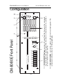
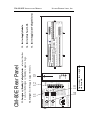
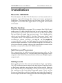
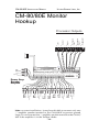
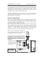
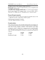
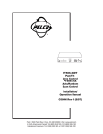
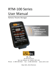
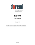
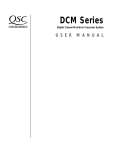
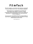
CM-80
CM-80E
Monitor
Monitor/
Exciter Supply
Quality Cinema Products
Ultra★Stereo Labs, Inc. • 181 Bonetti Drive,
- 1 CA
- 93401
San Luis Obispo,
Telephone (805) 549-0161
Issue 1. February, 1995
CM-80/80E INSTRUCTION MANUAL
ULTRA★STEREO LABS, INC.
One Year Limited Warranty
◆◆◆◆◆
Ultra★Stereo Labs warrants that each product manufactured
by it will be free from defects in material and workmanship
under normal usage for a period of one year after its
purchase new from an authorized dealer. Our obligation
under this warranty is limited to repairing or replacing any
product or component which we are satisfied does not
conform with the foregoing warranty and which is returned
to our factory, freight paid, or serviced by one of our
authorized contractors. The Foregoing Warranty is Exclusive
And in Lieu of All Other Warranties, Whether Expressed or
Implied. Such warranty shall not apply to any product or
component (A) repaired or altered by anyone other than
Ultra★Stereo Labs or an authorized service contractor; (B)
tampered with or altered in any way or subjected to misuse,
negligence or accident or (C) which has been improperly
connected, installed or adjusted otherwise than in
accordance with Ultra★Stereo Labs instruction.
Quality Cinema Products
Ultra★Stereo Labs, Inc.
181 Bonetti Drive
San Luis Obispo, CA 93401
USA
Telephone (805) 549-0161
FAX (805) 549-0163
© 1995, 1997
Ultra★Stereo Labs, Inc.
San Luis Obispo, CA, USA.
All Rights Reserved
-2-
CM-80/80E INSTRUCTION MANUAL
ULTRA★STEREO LABS, INC.
Table of Contents
Introduction ............................................................... 4
Configuration ............................................................ 6
Installation .............................................................. 11
Specifications .......................................................... 14
Please record the following information for your records:
Model: ___________________ Serial Number: _______________
Date of Purchase: _________ Purchased from: _____________
-3-
CM-80/80E INSTRUCTION MANUAL
ULTRA★STEREO LABS, INC.
Introduction
Please read this entire manual before commencing your
installation.
The ULTRA★STEREO CM-80 Projection Booth Monitor and
CM-80E Monitor/Exciter Supply have been designed for high
performance, ease of use, and years of trouble free service.
Installation and setup of the monitors has been considerably
simplified. No special tools are required. The built-in VU
meter and test jack gives the technician immediate information
about the status of the processor and all power amplifiers. All
controls necessary for daily operation of the processor are
easily accessible on the front panel.
The components that make up the CM-80/80E monitors are of
computer grade for reliability. All front panel controls are
individually sealed for long life. All ULTRA★STEREO equipment
has been “burned-in” at the factory for an extended period in
order to eliminate the possibility of premature failure.
Unpack the unit carefully. If the container has been damaged,
thoroughly inspect the equipment to make certain that there is
no hidden damage. File a claim immediately with the carrier
if any damage is found. Also advise your dealer or the factory.
TOOLS REQUIRED
DC
DC voltmeter
Trimpot
adjustment
tool
Wire strippers
No. 2 phillips
screwdriver
-4-
CM-80/80E INSTRUCTION MANUAL
ULTRA★STEREO LABS, INC.
You Will Need to Supply the Following Materials:
• Shielded audio cable for connecting the CM-80/80E to the
cinema processor and power amplifier outputs.
• Four 10-32 x 1/2" screws to mount the CM-80/80E in the
audio equipment rack.
• For the CM-80E only - 16ga. two conductor wire for lengths
up to 15ft., 14ga. up to 30ft.
FEATURES
All CM-80 and CM-80E monitors have the following
standard features:
• 8-Channel Monitoring - allows you to monitor both the
processor and power amplifier outputs to Left, Left Center,
Center, Right Center, Right, Surround Left, Surround Right
and Subwoofer channels, in any combination.
• Input levels from processor and power amplifier can be
adjusted independently - no huge level jumps when
switching between processor and power amplifiers.
• Bargraph display may be calibrated to the reference level for
your theatre - the projectionist can see auditorium levels
instantly.
• Designed to work with Bi or Tri- Amplified Sound Systems
to monitor the high, mid & low frequency outputs from the
left, left center, center, right center and right channels.
The CM-80E has the following additional features
• Plug-in DC Regulated Exciter Supply module – the entire
Exciter Supply may be replaced in seconds.
• Front panel bypass mode switch that switches the Exciter
Supply to a 5 or 8 volt AC power source in the event of a
failure of the DC Exciter Supply.
• Front panel status LEDs indicate power going into and
coming from the Exciter Supply module.
-5-
-6-
LC
C
R
1
CHANNEL SELECT
RC
LS
RS
Sub
2
3
1
2
5
6
10
0
VOLUME
4
9
8
7
3
AMPLIFIERS
PROCESSOR
VU
4
-40
-28
-34
-10
-16
-22
-1
-3
-5
-7
6
8
POWER
5-8 VOLTS
DC
JBX EXCITER
MODULE
5-8 VOLTS
AC/DC
OUTPUT
2. VOLUME CONTROL - controls the volume of the internal or external speaker. The
volume control has no effect on VU Bargraph display.
AC
EMERGENCY
DC
NORMAL
EXCITER SUPPLY
9
0
7
+3
+2
+1
TEST
5
1. CHANNEL SELECT Buttons - pressing a Channel Select button causes the corresponding LED to illuminate and the signal from that channel to be monitored. Any combination of 8 channels may be selected.
L
E IGHT C H A N N E L M O N I T O R
E X C I T E R S U P P LY
MODEL CM-80E
CM-80/80E Front Panel
10
CM-80/80E INSTRUCTION MANUAL
ULTRA★STEREO LABS, INC.
Configuration
-7-
10. DC OUTPUT Indicator - this LED illuminates when the DC Exciter Supply module is
installed and working properly.
9. AC EMERGENCY - DC NORMAL Indicator - this LED monitors the output of the exciter
supply. When the NORMAL/STANDBY switch is set to NORMAL, it monitors the output
of the Exciter Supply module; when in STANDBY mode, it monitors the AC Exciter
Supply output.
8. POWER Switch
7. NORMAL/STANDBY Switch - when set to "Normal" routes the Exciter Supply module
(pg. 10) (13) DC output to the Exciter Supply output terminals (pg. 10) (12). In "Standby"
mode it routes 8 or 5 VAC Bypass power to the output terminals.
6. Internal Speaker
5. TEST Jack - permits monitoring of the audio output of the CM-35/CM-35E. Inserting a
mono 1/4" phone plug here disables the internal speaker and routes the audio output to
the Test Jack. Do not connect any device here with less than 8Ω impedance.
4. VU Bargraph - displays the level of the selected channels. The VU Bargraph may be
calibrated by the rear panel trim adjustment (see 12, pg. 8). The VU Bargraph operates
independently of the volume control (2).
3. PROCESSOR/AMPLIFIER Selector Switch - selects either the inputs from the cinema
processor or power amplifiers for monitoring (see 5-8, pg. 8).
CM-80/80E INSTRUCTION MANUAL
ULTRA★STEREO LABS, INC.
FUSE
CM SERIES
RISK OF FIRE OR ELECTRIC
SHOCK DO NOT EXPOSE THIS
A P P L I A N C E TO R A I N O R
MOISTURE. DO NOT REMOVE
COVER. NO USER SERVICEABLE PARTS INSIDE. REFER
SERVICING TO QUALIFIED
PERSONNEL. FOR CONTINUED
PROTECTION AGAINST FIRE OR
SHOCK HAZARD REPLACE ONLY
WITH THE SAME FUSE TYPE
AND RATING.
WARNING: TO REDUCE THE
115V
PROJECTION BOOTH MONITOR
3
Some versions have the fuse and the
line switch in different locations.
1
ULTRA★STEREO LABS, Inc., 18730 Oxnard St. #208, Tarzana, CA 91356, 818-609-7405
INPUT: 115/230VAC, 50/60Hz
Model CM-Series: 15W, Model CM-E Series: 75W
MONITOR AMP
0.5ASB at 115V
0.25ASB at 230V
®
2
T2
LO
-
MID
+
L
HI
5
AMPLIFIER OUTPUTS
A
6
E
LO
MID
C
HI
LO
HI
E
LS
+
E
–
+
D
RS
+
-
T2
INTERNAL
SPEAKER
EXT SPKR
MID
C
AMPLIFIER OUTPUTS
B
SER.
NO.
E
LO
MID
LC
HI
E
R87
R86
R71
LO
LINE OUT
Pins 2-50
2
1
Pins 1-49
+
MID
HI
RC
T1
J4
Connector J2
SW
+
-
J2
4
L
E
-
J1
-
1
+
R
PROCESSOR OUTPUTS
-
-
+
-
J3A
LS
RS
+
-
25
SW
+
-
PROCESSOR OUTPUTS
U.S.L, INC., TARZANA, CA, U.S.A.
T3
+
C
7
Please Note: Connectors J2 & J3A are numbered 1-49 on the
top and 2-50 on the bottom. J1 is numbered as shown.
E
R
CM-80 EIGHT CHANNEL MONITOR
INTERNAL
SPEAKER
EXT SPKR
9
R107
CM-80/80E Rear Panel
R108
-8R109
+
-
RC
+
-
BARGRAPH
LEVEL
PROCESSOR
LEVEL
AMPLIFIER
LEVEL
LC
8
10
12
11
CM-80/80E INSTRUCTION MANUAL
ULTRA★STEREO LABS, INC.
-9-
10.
11.
12.
9.
8.
7.
6.
5.
1.
2.
3.
4.
AC Input
Line Voltage Selector
Main Fuse - 1/2 Amp for the CM-35 (1Amp for the CM-35E with single fuse and line switch).
Line Out - The Left, Center and Right channel signals are summed from processors and fed to this RCA jack.
Output level: nominal 100mv.
Amplifier Outputs - The amplifier outputs may be connected through a standard 50 conductor flat cable and
connector to J2. The pin assignments are as follows: 1. Lo left; 3. Mid left; 5. Hi left; 7. Lo center; 9. Mid center;
11. Hi center; 13. Lo right; 15. Mid right; 17. Hi right; 19. Left surr. +; 21. Left surr. -; 23. RIght surr. +; 25. Right
surr. -; 27. Subwoofer +; 29. Subwoofer -; 31-37 GND.; 39. Lo Left center; 41. Mid Left center; 43. Hi Left center;
45. Lo Right center; 47. Mid Right center; 49. Hi Right center.
Amplifier Outputs - connect these terminals to the power amplifier speaker outputs corresponding to Left, Center,
Right, Left and Right Surrounds, and Subwoofer. Left, Center and Right channels have high and low frequency
inputs for use with bi-amplified systems.
Processor Outputs - The processor outputs may be connected through a 25 pin "D" connector to J1. The pin
assignments are as follows: 2. Left +; 3. Left center -; 5. Center +; 6. Right center -; 8. Right +; 10. Surr. Left -; 11.
Surr. Right -; 12. Subwoofer -; 14. Left -; 16. Left center +; 17. Center-; 19. Right center+; 20. Right -; 23. Surr.
Left +; 24. Surr. Right +; 25. Subwoofer +.
Processor Outputs - connect these terminals to the cinema processor outputs corresponding to left, center, right,
left and right surrounds, and subwoofer.
Monitor Amp Out/Internal Speaker In - the Monitor Amp Output is linked to the Internal Speaker here. To
connect an external speaker, remove this link and connect the + and – terminals to the external speaker + and
– inputs. WARNING: Do not connect any device here with less than 8Ω impedance.
Processor Level - this trimpot adjusts the level of the input lines coming from the processor.
Amplifier Level - this trimpot adjusts the level of the input lines coming from the power amplifiers.
Bargraph Level - this trimpot adjusts the sensitivity of the front panel VU Bargraph meter.
CM-80/80E INSTRUCTION MANUAL
ULTRA★STEREO LABS, INC.
FUSE
CM SERIES
PROJECTION BOOTH MONITOR
FUSE
▲
RISK OF FIRE OR ELECTRIC
SHOCK DO NOT EXPOSE THIS
A P P L I A N C E TO R A I N O R
MOISTURE. DO NOT REMOVE
COVER. NO USER SERVICEABLE PARTS INSIDE. REFER
SERVICING TO QUALIFIED
PERSONNEL. FOR CONTINUED
PROTECTION AGAINST FIRE OR
SHOCK HAZARD REPLACE ONLY
WITH THE SAME FUSE TYPE
AND RATING.
WARNING: TO REDUCE THE
DC ADJUST
GN
D
V+
AC EMERGENCY
DC NORMAL
DC OUTPUT
EXCITER SUPPLY
13
T2
LO
-
MID
+
L
HI
AMPLIFIER OUTPUTS
A
E
LO
MID
C
HI
E
LO
MID
R
HI
B
C
D
E
+
LS
E
RS
+
-
+
SW
-
E
LO
HI
E
R87
R86
R71
LO
LINE OUT
LC
MID
J2
+
MID
HI
RC
T1
J4
L
E
-
J1
-
1
+
R
PROCESSOR OUTPUTS
-
-
+
-
J3A
LS
RS
+
-
25
SW
+
-
PROCESSOR OUTPUTS
U.S.L, INC., TARZANA, CA, U.S.A.
T3
+
C
+
-
RC
+
-
BARGRAPH
LEVEL
PROCESSOR
LEVEL
AMPLIFIER
LEVEL
LC
15. Exciter Supply Line Voltage Selector.
14. Exciter Main Fuse 1A SB.
13. Exciter Supply Module.
SER.
NO.
AMPLIFIER OUTPUTS
CM-80 EIGHT CHANNEL MONITOR
INTERNAL
SPEAKER
EXT SPKR
Some versions have a single fuse
and line switch.
14 15
5 VAC
8 VAC
–
OUTPUT
+
EXCITER LAMP
SUPPLY
12
ULTRA★STEREO LABS, Inc., 18730 Oxnard St. #208, Tarzana, CA 91356, 818-609-7405
INPUT: 115/230VAC, 50/60Hz
Model CM-Series: 15W, Model CM-E Series: 75W
MONITOR AMP
0.5ASB at 115V
0.25ASB at 230V
SET BOTH LINE SWITCHES TO THE SAME POSITION
EXCITER LAMP
SUPPLY
1ASB at 115V
0.5ASB at 230V
®
11
12. Output - Exciter Supply output terminals.
11. Emergency (Standby) Voltage Selector - selects either 8 or
5 volts for the Emergency (Standby) output voltage.
CM-80E Rear Panel
115V
115V
▲
- 10 -
EMERGENCY
CM-80/80E INSTRUCTION MANUAL
ULTRA★STEREO LABS, INC.
CM-80/80E INSTRUCTION MANUAL
ULTRA★STEREO LABS, INC.
Installation
Mount the CM-80/80E
The ideal place for the CM-80 Monitor is in the sound rack or
projector console between the stereo processor and power
amplifiers. The terminal blocks on the rear of the CM-80 are
designed to facilitate the application of stripped and tinned
wire leads.
Monitor Hookup
Follow the illustration on page 12 to connect the CM-80 and
make sure all cable shields are tied at only one end to their
ground wire to prevent hum. The terminals on the CM-80/80E
are such that no spade lugs are necessary. Use a high quality
cable such as Belden #8451. Set the "Processor Level" and
"Amplifier Level" trim adjustments to their mid positions. For
installations where speakers are not bi or tri-amplified,
connect the left, center, and right amplifier inputs to their ‘Low’
monitor input terminals. If you will be using the CM-80/80E to
drive an external speaker, remove the jumper that connects the
Speaker + terminal to the INT SPKR terminal.
Split Surround Processors
For connection to split-surround processors such as the
Ultra★Stereo model JS-230, connect the Left and Right processor
outputs to the CM-80 Surround Left and Surround Right inputs,
respectively.
Setting Levels
Run a pink noise test film such as Ultra★Stereo Type 1 or Dolby®
Cat. 69. Set the processor main fader and power amplifier levels
so the house speakers are playing back at the normal listening
level. Set the Processor/Amplifier switch to Processor and note
the reading on the front panel bargraph meter. Next, set the
Processor/Amplifier switch to Amplifier, and adjust the Amplifier
Level trimpot on the rear of the unit for the same bargraph reading.
- 11 -
CM-80/80E INSTRUCTION MANUAL
ULTRA★STEREO LABS, INC.
CM-80/80E Monitor
Hookup
+
EXT SPKR
–
+
-
+
J2
A
C
-
PROCESSOR OUTPUTS
1
+
Subwoofer
Surround
Right
+
-
LC
+
-
RC
+
-
+
L
-
+
C
-
25
PROCESSOR OUTPUTS
+
R
-
+
LS
-
+
RS
-
SW
+
-
T1
D
R87
R86
R71
G
N
D
CM-80 EIGHT CHANNEL MONITOR
+
J1
J4
SER.
NO.
B
Surround
Left
-
LINE OUT
AMPLIFIER OUTPUTS
INTERNAL
SPEAKER
Left
Channel
- +
Right
Left
Center
Processor Outputs
AMPLIFIER OUTPUTS
Mid Freq.
(Optional)
Hi Freq.
L
LO
MID
C
HI
E
LO
MID
R
HI
E
LO
MID
HI
+
E
LS
-
E
RS
+
-
+
SW
-
RC
LC
E
LO
MID
HI
E
LO
MID
HI
E
AMPLIFIER
LEVEL
J3A
T3
PROCESSOR
LEVEL
-
U.S.L, INC., TARZANA, CA, U.S.A.
T2
BARGRAPH
LEVEL
Power Amp
Speaker
Outputs
Mid Freq.
(Optional)
Hi Freq.
Right
Center
Mid Freq.
(Optional)
Hi Freq.
Left
Center
Subw.
Channel
Right
Surround
Left
Surround
G
N
D
Mid Freq.
(Optional)
Hi Freq.
G
N
D
G
N
D
Right
Channel
G
N
D
G
N
D
Mid Freq.
(Optional)
Hi Freq.
G
N
D
Center
Channel
G
N
D
Note: on some installations, it may be advisable to connect only one
'-' amplifier speaker terminal to the CM-80/80E to prevent ground
loops. Do not connect the '-' amplifier speaker terminal to the CM-80/
80E if the amplifier is in the "bridge" mode.
- 12 -
-
CM-80/80E INSTRUCTION MANUAL
ULTRA★STEREO LABS, INC.
If there is an unusually large difference between the processor
and amplifier levels it may be necessary to go back and adjust
the Processor Level trimpot to match levels. Next, set the
Bargraph Level trimpot on the rear of the unit so the front panel
bargraph meter reads approximately 0VU.
With the bargraph meter set to read 0VU at normal auditorium
listening levels, the projectionist can tell at a glance if a film is
playing at the correct level.
Exciter Supply Setup
The Exciter Lamp Supply is built on the JBX printed circuit
board, which plugs into the back of the CM80E. This electronic
switching supply is adjustable from 3.7 to 8.5 VDC with a
maximum current output of 7 amps.
Use a minimum of 16ga. cable no more than 15 feet in length
(14ga. cable for up to 30 feet) to connect the Exciter Lamp to
the Exciter Lamp Supply Output terminals. Make sure the
negative (–) contact of the exciter lamp does not contact the
projector frame or any other possible common ground.
Set the AC Standby voltage by
loosening the jumper link and moving
to either the 8V or 5V position.
If the negative Exciter Lamp Supply terminal of
the CM-80E is connected to a chassis or
common ground, or is connected to the
projector chassis, then excessive hum or noise
may result.
Connect the Exciter
CM SERIES
Lamp only to the
'–' output terminal on
the Exciter Lamp Supply
terminal block.
®
EXCITER SUPPLY
115V
PROJECTION BOOTH MONITOR
FUSE
SET BOTH LINE SWITCHES TO THE SAME POSITION
FUSE
WARNING: TO REDUCE THE
Some versions
have a single fuse
and line switch.
RISK OF FIRE OR ELECTRIC
SHOCK DO NOT EXPOSE THIS
A P P L I A N C E TO R A I N O R
MOISTURE. DO NOT REMOVE
COVER. NO USER SERVICEABLE PARTS INSIDE. REFER
SERVICING TO QUALIFIED
PERSONNEL. FOR CONTINUED
PROTECTION AGAINST FIRE OR
SHOCK HAZARD REPLACE ONLY
WITH THE SAME FUSE TYPE
AND RATING.
INPUT: 115/230VAC, 50/60Hz
Model CM-Series: 15W, Model CM-E Series: 75W
ULTRA★STEREO LABS, Inc., 18730 Oxnard St. #208, Tarzana, CA 91356, 818-609-7405
- 13 -
DC OUTPUT
DC Supply
"active" LED
▲
115V
▲
MONITOR AMP
0.5ASB at 115V
0.25ASB at 230V
EXCITER LAMP
SUPPLY
+
OUTPUT
–
8 VAC
5 VAC
EMERGENCY
EXCITER LAMP
SUPPLY
1ASB at 115V
0.5ASB at 230V
AC EMERGENCY
DC NORMAL
V+
AC or DC
"active" LED
Test points
GN
D
DC ADJUST
Adjust DC
voltage
CM-80/80E INSTRUCTION MANUAL
ULTRA★STEREO LABS, INC.
Specifications
Inputs
Processor: Eight inputs corresponding to Left, Left Center,
Center, Right Center, Right, Surround Left, Surround Right and
Subwoofer. Input impedance is 10kΩ.
Power Amp: Seventeen inputs corresponding to Left Lo, Mid
&Hi, Left Center Lo, Mid & Hi, Center Lo, Mid & Hi, Right
Center Lo, Mid & Hi, Right Lo, Mid & Hi, Surround Left,
Surround Right and Subwoofer. Input impedance is greater
than 50kΩ.
Outputs
The monitor output may be routed to either the CM-80/80E
internal speaker or to the external speaker terminal via a
removeable jumper on the rear of the unit. Maximum output 10
Watts RMS. Minimum output impedance: 8Ω. Line output:
nominal 100mv.
Exciter Supply Output (CM-80E only)
DC output: 3.7 - 8.5VDC. 7A maximum.
AC output: 8 or 5VAC, selectable.
Controls
Front Panel: Individual push button switches for each input
channel toggle on and off so that channels may be monitored
in any combination. An LED indicator illuminates when the
corresponding channel is selected. A volume control sets the
speaker output level and works independently of the front
panel VU bargraph meter. A push button switch with
corresponding LED switches monitoring between the Processor
and Amplifier inputs. A 14 segment bargraph VU Meter indicates
the input level from -40 to +3VU. On the CM-80E the Normal/
Standby switch routes either the normal DC or emergency AC
- 14 -
CM-80/80E INSTRUCTION MANUAL
ULTRA★STEREO LABS, INC.
voltage to the Exciter Supply output terminals.
Rear Panel: Three Trimpots adjust the Processor, Amplifier and
VU Meter input levels.
CM-80E Exciter Supply module only: A 15 turn trimpot adjusts
the Exciter Supply DC output from 3.7 to 8.5VDC. LED’s
indicate DC output and AC Emergency/DC Normal status.
Power Requirements
A two position switch on the rear of the CM-80/80E selects 106
~ 125 VAC or 212 ~ 250 VAC, 50-60 cycles.
CM-80: approximately 15 watts.
CM-80E: approximately 52 watts.
Construction
The CM-80 Monitor and CM-80E Monitor/Exciter Supply are
constructed of steel to minimize hum pickup and noise radiation
from the Exciter Supply module. Gold plated card edge
connectors and 1% precision components are used throughout. The overall size of the unit is 5.22" x 19" x 8". The CM-80
and CM-80E are designed to mount in a standard rack frame or
cabinet.
CM-80
CM-80E
Weight:
10 lbs.
17 lbs.
Shipping Weight:
12 lbs.
19 lbs.
- 15 -