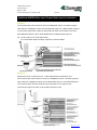
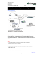
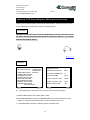
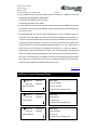
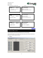
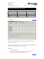
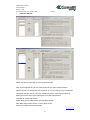
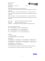
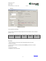
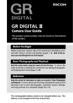
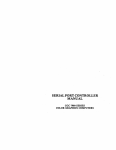
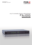
1
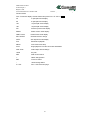
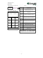
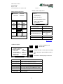
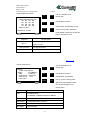
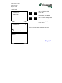
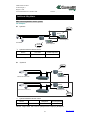
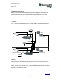
24020 Rovetta S.Lorenzo
Via Don Arrigoni, 5
Bergamo – Italia
Tel.+39 0346 750011 Fax. +39 0346 71436
Internet: http//www.comelit.it
E-mail: [email protected]
TOUCH PANEL LCD
CONTROL KEYBOARD ART. 45290
And
MATRIX ART. 45208-45216-45232
Product User Manual
1
24020 Rovetta S.Lorenzo
Via Don Arrigoni, 5
Bergamo – Italia
Tel.+39 0346 750011 Fax. +39 0346 71436
Internet: http//www.comelit.it
E-mail: [email protected]
MENU PAGE
Touch Panel Type LCD: Control Keyboard………………………………………………………….5
Touch Panel Type LCD: Control Keyboard LCD Menu Page……………………………………..6
Touch Panel LCD Control Keyboard: Menu Function Setup………………………………………8
MATRIX: Device video cable connecting………………………………………………………….. 11
MATRIX: Function Statement………………………………………………………………………..12
MATRIX: The Rear Panel……………………………………………………………………………13
MATRIX: Video input and Expand Video Input x2U……………………………………………….13
MATRIX: Expand PCI Card and Video Input xU collocation……………………………………...15
MATRIX: Rear Panel / Video Input / Expand Video Input Define………………………………...17
MATRIX: Video input xU connect collocation………………………………………………………18
MATRIX System: All Device control cable connecting……………………………………………19
All Device RS-458 Interface…………………………………………………………………………20
All Device connecting………………………………………………………………………………...21
Touch Panel LCD Type Control Keyboard: Call Device and control…………………………….31
P/T/Z Dome function setup…………………………………………………………………………..32
Additional: Alarm In / Relay and RS232 Pin Define……………………………………………….43
Additional: Why Matrix……………………………………………………………………………….44
Additional: Control Keyboard Single mode connecting…………………………………………...47
Additional: MATRIX Video Input / Expand Video Input xU collocation…………………………..40
Additional: P/T/Z Dome, Multiplexer, DVR remote function setup……………………………….46
Additional: Control Command Display……………………………………………………………...49
Additional: Matrix wizard……………………………………………………………………………..52
Protocol………………………………………………………………………...…..52
Video / Device ID…………………………………………………………………..53
Matrix Device ID and video channel contrast table…………………………….55
Video Title…………………………………………………………………………..55
Controller / Monitor………………………………………………………………..56
Authority……………………………………………………………………………58
Alarm Trigger………………………………………………………………………59
Relay Duration Time………………………………………………………………60
Alarm Out Title……………………………………………………………………..61
2
24020 Rovetta S.Lorenzo
Via Don Arrigoni, 5
Bergamo – Italia
Tel.+39 0346 750011 Fax. +39 0346 71436
Internet: http//www.comelit.it
E-mail: [email protected]
PRECAUTION
The lightning flash with arrowhead symbol, within an
equilateral triangle, is intended to alert the user to the
presence of insulated dangerous Voltage within the
product’s enclosure that may be sufficient magnitude
to constitute risk of electrical shock to persons.
The exclamation point within an equilateral triangle is
intended to alert the user to the presence of important
operation and maintenance (servicing) instructions in
the literature accompanying the appliance.
Precautions
Before using this unit, please read these operating instructions carefully.
Take special care to
the follow the warnings indicated on the unit itself as well as the safety suggestions listed
below.
Keep them handy for future reference.
1. Power source – The unit operates on 12V 1A of power.
2. Power cord protection – AC power supply cords should be routed so that they are not
likely to be walked on or pinched by items placed upon or against them.
Never take hold
of the plug or cord if your hand is wet, and always grasp the plug body when connecting or
disconnecting it.
3. Water and Moisture – Do not use this unit near the sources of water for moisture will
damage the internal parts.
4. Heat – Do not install the unit near heat sources such as radiators, stoves, heat registers,
or other appliances that product heat.
5. Ventilation – The unit should be situated so that its location or position does not interfere
with its proper ventilation.
6. Foreign Material – Extremely caution should be taken so that the objects do not fall into
the unit.
3
24020 Rovetta S.Lorenzo
Via Don Arrigoni, 5
Bergamo – Italia
Tel.+39 0346 750011 Fax. +39 0346 71436
Internet: http//www.comelit.it
E-mail: [email protected]
7. Surface – Place the unit on a flat, level surface or the unit may fall causing serious
damages to the unit.
8. Damage Requiring Service – The unit should be serviced by qualified service personnel
when:
The power cord or the plug has been damaged; or
Objects have fallen or liquid has been spilled into the unit; or the unit has been
exposed to rain or water; or
The unit does not appear to operated normally or exhibits a marked change in
performance; or
The unit has been dropped, or the enclosure damaged.
9. Replacement Parts – Use only manufacturer specified parts.
Unauthorized substitutions
may result in fire, electrical shock or other hazards.
10. Service – Should not attempt to service the unit beyond that described in the operating
instructions.
All other servicing should be referred to an authorized service personnel.
Notification: This device complies with Part 15 of the FCC rules.
Operation is subject
to the following two conditions: 1)This device may not cause harmful interference and
2) This device must accept any interference received,
may cause undesired operation.
4
including interference that
24020 Rovetta S.Lorenzo
Via Don Arrigoni, 5
Bergamo – Italia
Tel.+39 0346 750011 Fax. +39 0346 71436
Internet: http//www.comelit.it
E-mail: [email protected]
Touch Panel Type LCD: Control Keyboard
Command Buttons
Joystick
LCD Touch Panel
Command Buttons
LCD Touch Panel
Joystick
Touch Pan
LED
Touch Pan hole
360。Joystick
5
24020 Rovetta S.Lorenzo
Via Don Arrigoni, 5
Bergamo – Italia
Tel.+39 0346 750011 Fax. +39 0346 71436
Internet: http//www.comelit.it
E-mail: [email protected]
Touch Panel Type LCD: Control Keyboard LCD Menu Page
Key
Function Define
0~9
Numeric buttons. Call Device ID
CAM
Call Camera ID.
Numeric (ID) + CAM
MUX
Call Multiplexer ID.
Numeric (ID) + MUX
DVR
Call DVR ID.
MAT
Call Matrix ID.
MON
Call Monitor ID.
SLOW
P/T/Z Dome slow speed move mode on and off.
LOG IN
Matrix user login.
(Only for Matrix Mode use)
LOG OUT
Matrix user logout.
(Only for Matrix Mode use)
LOCK
Key / joy / touch lock.
Numeric (ID) + DVR
Numeric (ID) + MAT
Numeric (ID) + MON
Key Lock (Press until 3 sec)
After, insert password to unlock.
ENT
Enter.
ESC
ESC / CLR Preset.
MENU
Enter setup menu.
PRESET
Call preset.
SET
Set preset.
CLR
Clear preset one by one. (Preset + CLR press until 3 sec)
(Preset + SET press until 3 sec)
77 + SET press until 3 sec clear all preset.
ZOOM IN
Zoom in.
ZOOM OUT
Zoom out.
IRIS OPEN
IRIS open.
IRIS CLOSE
IRIS close.
FOCUS FAR
Focus far.
FOCUS NEAR
Focus near.
MISC1
Reserve.
MISC2
Reserve.
AUTO IRIS
Enable auto iris.
AUTO FOCUS
Enable auto focus.
AUTO TOUR
Auto Tour On/Off.
UP
Direct up.
DOWN
Direct down.
LEFT
Direct left.
RIGHT
Direct right.
LED
Tour/Focus/IRIS/Power.
6
24020 Rovetta S.Lorenzo
Via Don Arrigoni, 5
Bergamo – Italia
Tel.+39 0346 750011 Fax. +39 0346 71436
Internet: http//www.comelit.it
E-mail: [email protected]
The P/T/Z Dome menu page after power on:
CAM: 001
MUX:000
DVR: 000
MON:000
>
Description:
Factory default displays the HISHARP protocol
P/T/Z dome control function page.
ZOOM
FOCUS
SPEED
SPEED
RIGHT
LEFT
LINE
LIMIT
LIMIT
SCAN
MENU
MENU
STOP
UP
SET
SCAN
MENU
PAN
DOWN
ZERO
FLIP
P/T/Z dome control function page would display different
if user choose others P/T/Z dome protocol.
Please setup all control keyboard system menu before
start to control all device. See the control keyboard menu
setup. Single mode only use keyboard menu to setup.
MENU
HISHARP CAMERA YY MM/DD HH/MM/SS
Matrix mode needs to setup by PC Matrix wizard.
Function Define:
CAM: 000 - CAM ID. Display the CAM ID after call camera.
CAM: 001
MUX:000
DVR: 000
MON:000
>
ZOOM
FOCUS
SPEED
SPEED
RIGHT
LEFT
LINE
LIMIT
LIMIT
SCAN
MENU
MENU
STOP
UP
SET
SCAN
MENU
PAN
DOWN
ZERO
FLIP
MENU
HISHARP CAMERA YY MM/DD HH/MM/SS
MUX: 000 - MUX ID. Display the MUX ID after call Multiplexer.
DVR: 000 - DVR ID.
Display the DVR ID after call DVR.
MON: 000 - MON ID.
Display the MON ID after call Monitor.
ZOOM SPEED:
Image zoom in and out speed setup.
FOCUS SPEED:
Image focus speed setup.
FLIP:
Auto 180。Flip.
RIGHT LIMIT:
Line scan right position setup.
LEFT LIMIT:
Line scan left position setup.
LINE SCAN:
Start line scan.
MENU UP:
P/T/Z dome OSD menu direction UP.
MENU SET:
P/T/Z dome OSD menu values confirm.
STOP SCAN:
Line scan stop.
MENU DOWN:
P/T/Z dome OSD menu direction down.
PAN ZERO:
If the preset position is not correct, pan zero to reset.
Menu
Go to P/T/Z Dome OSD function menu setup
HISHARP CAMERA Now controlling the HISHARP protocol P/T/Z dome.
YY MM/DD HH/MM/SS
7
Local date and time displays.
24020 Rovetta S.Lorenzo
Via Don Arrigoni, 5
Bergamo – Italia
Tel.+39 0346 750011 Fax. +39 0346 71436
Internet: http//www.comelit.it
E-mail: [email protected]
Touch Panel LCD Control Keyboard: Menu Function Setup
Device controlling by LCD panel control keyboard:
1. P/T/Z dome
-- Protocol: HISHARP / PELCO-D / PELCO-P / LILIN
PS. The P/T/Z dome maximum controls check the company specifications.
2. Multiplexer
- 9 CH / 16 CH Multiplexer. Total maximum is 16.
Notice: Multiplexer Protocol must be compatible.
3.
DVR
--1 CH / 4 CH DVR. Total maximum is 16.
Notice: DVR Protocol must be compatible.
4.
Matrix
-- All devices connect to Matrix. Control functions go through RS-485 interface.
Main controller is the control keyboard.
Notice: All device (Multiplexer and DVR) protocol must be the same if goes through Matrix
system.
Press MENU button to pop-up control keyboard system function setup:
CAM: 001
MUX:000
DVR: 000
MON:000
Main function menu page:
1. SYSTEM SETUP
>
2. REMOTE SETUP
SYSTEM SETUP
3. LCD SCREEN SETUP
REMOTE SETUP
4. BUZZER SETUP
LCD SCREEN SETUP
5. DATE AND TIME
BUZZER SETUP
6. ABOUT SYSTEM
DATE AND TIME
7. LOAD DEFAULT
ABOUT SYSTEM
8. EXIT MENU
LOAD DEFAULT
EXIT MENU
Direction Up and Down
ESC
ENT
ESC: Menu exit
ENT: Function values confirm
Back to MENU
8
24020 Rovetta S.Lorenzo
Via Don Arrigoni, 5
Bergamo – Italia
Tel.+39 0346 750011 Fax. +39 0346 71436
Internet: http//www.comelit.it
E-mail: [email protected]
SYSTEM SETUP
User can use touch pan double click the function
CAM: 001
MUX:000
item, with the touch panel LCD
ESC ENT to
DVR: 000
MON:000
choose which function setup is going to in.
Or use the buttons on the keyboard,
>
Press ENT to start sub-menu. Needs to press ENT
LANGUAGE
again the mode window would become blink, use
SYSTEM SETUP
U Up/Down key to change values. Needs to press ENT
REMOTE SETUP
to confirm value set after user change every item
LCD SCREEN SETUP
value. Press ESC until back to P/T/Z dome menu
BUZZER SETUP
page or choose EXIT MENU to back P/T/Z dome
DATE AND TIME
menu page.
ABOUT SYSTEM
LOAD DEFAULT
SYSTEM SETUP:
EXIT MENU
Setup the control keyboard system mode and function.
P.S: If user choose SINGLE mode, cannot connect
ESC
ENT
any more keyboards, except needs to choose
MATRIX mode. See page why Matrix?
Function mode menu page:
Function Setup:
CAM: 001
MUX:000
DVR: 000
MON:000
1. LANGUAGE (Choose English or Chinese version)
ENGLISH / CHINESE
2. SYSTEM MODE (Choose system mode)
>
LANGUAGE
SINGLE / MATRIX
3. SYSTEM ID (Choose the keyboard system ID)
SYSTEM MODE
SYSTEM ID
01 ~ 16
4. SCREEN SAVE TIME (Screen save time setup)
SCREEN SAVE TIME
AUTO LOGOUT TIME
ON/OFF
5. AUTO LOGOUT TIME (Auto log out time setup)
ALARM RESET TIME
PASS WORD
ON/OFF 5/10/15
6. ALARM RESET TIME (Alarm duration time setup)
LAST PAGE
1~20MIN / OFF
7. PASS WORD (Password reset)
SYSTEM MODE
SINGLE
ESC
ENT
********.
Factory set is 10000001. 8 characters.
8. LAST PAGE (Choose back to the main menu)
Press ENT back to the main menu page.
9
24020 Rovetta S.Lorenzo
Via Don Arrigoni, 5
Bergamo – Italia
Tel.+39 0346 750011 Fax. +39 0346 71436
Internet: http//www.comelit.it
E-mail: [email protected]
SINGLE mode: Only one control keyboard in the system. Single mode can be includes these
systems below.
For Example:
System A:
Monitor
P/T/Z Dome
SINGLE Control Keyboard
System A Maximum device control:
Device
P/T/Z Dome
Control Keyboard
Maximum
X1
X1
* Monitor: Image viewer: Full screen display.
System B:
Monitor
SINGLE Control Keyboard
Cameras or P/T/Z Dome
Multiplexer
System B Maximum device control:
Device
Maximum
P/T/Z Dome
Multiplexer
Control Keyboard
X16
X1
X1
*Monitor: Image viewer. Full screen or quad split screen display by Multiplexer.
PS: DVR can be added in the system to record video image.
MATRIX mode: User choose the control keyboard on Matrix mode, keyboard connects up to 8
through matrix. Others device such as P/T/Z Dome up to 256; Multiplexer up to 16; DVR up to
16. Multi user can view and control each camera or P/T/Z Dome video image in different place.
Back to MENU
10
24020 Rovetta S.Lorenzo
Via Don Arrigoni, 5
Bergamo – Italia
Tel.+39 0346 750011 Fax. +39 0346 71436
Internet: http//www.comelit.it
E-mail: [email protected]
MATRIX: Device video cable connecting
Matrix: The total maximum device video cable connecting.
Camera video output x128
Monitor x16
Monitor x16
Multiplexer x8
Keyboards x4
DVR x8
Camera video output x128
Matrix
Multiplexer x8
Keyboards x4
DVR x8
is video cable.
Video cable connecting define:
> Matrix mode is useful if video input more than 16 CHs. User can also depends on how big
the video source input to consider expand PCI card and Video Input xU. User can collocation
Multiplexer and DVR to display in full or quad split screen on the monitor. Matrix video input
connecting is
> Matrix Video Input xU and Expand Video Input x1U:
The standard Matrix device is a main Matrix machine( 8 / 16 / 32 monitor out optional).
Video Input x1U. Expand Video Input x1U. Users need to consider camera video source in the
place and environment, the system is going to be small or large? So user can make purchase
expand PCI card. There are 7 expand PCI card can be added. 1 expand PCI follows a
Video Input x1U.
Back to MENU
11
24020 Rovetta S.Lorenzo
Via Don Arrigoni, 5
Bergamo – Italia
Tel.+39 0346 750011 Fax. +39 0346 71436
Internet: http//www.comelit.it
E-mail: [email protected]
PS.
1. Each Video Input x1U can import x32 CH in.
2. Expand Video Input x1U is static. No more expand. x16 CH maximum video input.
MATRIX: Function Statement
Function:
1. 8 / 16 / 32 Monitor Out (Optional)
2. Video Input Expand. Maximum 256 video input. (PCI Card Optional)
3. RS-485 Port x 16. For command control.
4. Control Keyboard x8. Multi user control. Maximum x 32-users control.
5. HISHARP / PELCO-D / PELCO-P / LILIN Protocol
6. Alarm In / Relay: Minimum x8.
Maximum x256.
7. Camera Title Setup. (English)
8. Expand PCI Card Hot insert and pull out.
9. RS-485 interface link for control keyboard, multiplexer. DVR, and P/T/Z Dome.
10. P/T/Z Dome maximum control x256.
11. Multiplexer maximum control x16 / DVR maximum control x16.
Specifications:
Model: 45208 / 45216 / 45232
>Video Input:
Mini. 32 channels, extendable to Max. 256 channels, BNC connector
Standard 1U, each contains 32 signals.
(Input either directly from camera or from multiplexer looping)
>Expand Video Input:
Standard 1U, each contains 16 video sources from multiplexer/DVR.
>Monitor Out:
8/16/32 Monitoring out(Optional)
Quad: Full, 4/9/16 screen (depends on multiplexer type)
Enlarge: Live/DVR Zoom in x 2 (depends on multiplexer and DVR type)
Monitor: Auto Sequence
>Interface:
RS232: RS232 interface for system data transfer set up
RS485: RS485 for Interface Device control link
>Alarm:
Input: Mini. 8 alarm input, expand to max. 256-alarm input
12
24020 Rovetta S.Lorenzo
Via Don Arrigoni, 5
Bergamo – Italia
Tel.+39 0346 750011 Fax. +39 0346 71436
Internet: http//www.comelit.it
E-mail: [email protected]
Relay: Mini. 8 relay output, expand to max. 256 relay output
Alarm Relay Mode: Relay arrangement. Monitor Display, Preset Display, DVR Record.
>Title Display: Monitor Number, Video Title, Alarm Title, Relay Title, Time-Date.
>Video System: NTSC / PAL
Back to MENU
>Power: AC 110~240V
MATRIX: The Rear Panel
Expand PCI card
Monitor BNC output
Video Input
Expand Video Input
RS-232
Alarm Expand
Alarm Output
Alarm Input
RS-458
Power code
MATRIX: Video input and Expand Video Input x2U
Video Input x1U. Total is x32 CH input. Video source from MUX video looping.
Every time add the expand card equal add the Video Input x1U.
13
24020 Rovetta S.Lorenzo
Via Don Arrigoni, 5
Bergamo – Italia
Tel.+39 0346 750011 Fax. +39 0346 71436
Internet: http//www.comelit.it
E-mail: [email protected]
Expand Video Input x1U. Total is x16 video input. Video source from MUX or DVR Monitor
Out.
Other x16 CH Reserve.
Back to MENU
PS. This Expand Video Input x 1U is static. User cannot expand.
14
24020 Rovetta S.Lorenzo
Via Don Arrigoni, 5
Bergamo – Italia
Tel.+39 0346 750011 Fax. +39 0346 71436
Internet: http//www.comelit.it
E-mail: [email protected]
MATRIX: Expand PCI Card and Video Input xU collocation
Matrix 8 monitor out
Standard:
Expand PCI Card: x0
Video Input: x 1U. x32 CH input
Expand Video Input: x1U. x16CH input
Expanding:
PCI card: Expand up to 7 PCI card
Video Input x1U follows 1 PCI card
Total is Video Input x8U
Expand Video Input x1U is static.
It cannot expand.
Matrix 16 monitor out
Standard:
Expand PCI Card: x0
Video Input: x 1U. x32CH input
Expand Video Input: x1U x16CH input
Expanding:
PCI card: Expand up to 7 PCI card
Video Input x1U follows 1 PCI card
Total is Video Input x8U
Expand Video Input x1U is static.
It cannot expand.
15
24020 Rovetta S.Lorenzo
Via Don Arrigoni, 5
Bergamo – Italia
Tel.+39 0346 750011 Fax. +39 0346 71436
Internet: http//www.comelit.it
E-mail: [email protected]
Matrix 32 monitor out
Standard:
Expand PCI Card: x0
Video Input: x 1U
Expand Video Input: x1U
Expanding:
PCI card: Expand up to 7 PCI card
Video Input x1U follows 1 PCI card
Total is Video Input x8U
Expand Video Input x1U is static.
It cannot expand.
Back to MENU
16
24020 Rovetta S.Lorenzo
Via Don Arrigoni, 5
Bergamo – Italia
Tel.+39 0346 750011 Fax. +39 0346 71436
Internet: http//www.comelit.it
E-mail: [email protected]
MATRIX: Rear Panel / Video Input / Expand Video Input Define
Interface \ Matrix
Matrix 8 monitor out
Matrix 16 monitor out
Matrix 32 monitor out
Matrix Rear Panel
Smallest: 8 Channel
Medium: 16 Channel
Largest: 32 Channel
BNC Connector
Video Input IDE
Interface
Expand Video Input
IDE Interface
Expand PCI
RS-232
Monitor output
Monitor output
Monitor Output
Rear panel of Matrix Video Input IDE connects to Video Input x1U IDE
Expand Video Input IDEx 1. Expand Video Input x1U
Maximum 7 PCI card can expand.
One Video Input follows an expand PCI card.
PC RS232 interface connect to Matrix to transfer system data.
Alarm Input
Minimum 8 Alarm input. Maximum 256 Alarm input.
Alarm Output
Minimum 8 Relay. Maximum 256 Relay.
Alarm Expand
Standard is Minimum 8 Alarm input and 8 Relay.
Alarm Expand up to 256 input and 256 Relay.
Total x16 ports.
RS-458
1~8 port connect control keyboard.
9~15 port connect P/T/Z Dome.
16 port connect Multiplexer and DVR.
Power Code
Power code connecting and turn on/off switcher
Video source from camera input directly or from Multiplexer video
Video Input x1U
looping. Each Video Input x1U allows x32CH input. Total maximum
Video Input is x8U. Video input collocation can be:
32/48/64/80/96/112/128/144/160/176/192/208/224/240/256 CH.
Total video input is x16CH. Video source from Multiplexer or
Expand Video Input
DVR Monitor Out.
The others x16CH input is reserve.
Back to MENU
17
24020 Rovetta S.Lorenzo
Via Don Arrigoni, 5
Bergamo – Italia
Tel.+39 0346 750011 Fax. +39 0346 71436
Internet: http//www.comelit.it
E-mail: [email protected]
MATRIX: Video input xU connect collocation
Example 1:
x16 CH video input. Camera video out connect to Multiplexer video in. x16 video looping to
Video input x1U. Multiplexer monitor out to Expand Video In x1U.
Every Video In x1U can be input x32CH.
Example 2:
x32 CH video input. Camera video put connect to Multiplexer x2 video in. Total video in is x32.
x32 video looping to Video In x1U. Multiplexer x2 monitor out to Expand Video In x1U.
Back to MENU
18
24020 Rovetta S.Lorenzo
Via Don Arrigoni, 5
Bergamo – Italia
Tel.+39 0346 750011 Fax. +39 0346 71436
Internet: http//www.comelit.it
E-mail: [email protected]
PS: Please see the reference Additional: MATRIX Video Input / Expand Video Input xU
collocation.
MATRIX System: All Device control cable connecting
Matrix: The total maximum device control cable connecting.
HISHARP protocol P/T/Z Dome
LILIN protocol P/T/Z Dome
Multiplexer
DVR
Keyboard x4
PELCO-D protocol P/T/Z Dome
Matrix
PELCO-P protocol P/T/Z Dome
Multiplexer
Keyboard x4
DVR
is RS-485 control cable.
RS-485 control define:
Total is 16 RS485 ports of Matrix rear panel. 1~8 ports are for control keyboard RS485,
maximum is 8 keyboards. 9~15 ports are for P/TZ Domes. Current there are HISHARP;
PELCO-D; PELCO-P and LILIN can choose. 16 port is for Multiplexer and DVR RS485.
Each device must have their own ID.
Back to MENU
19
24020 Rovetta S.Lorenzo
Via Don Arrigoni, 5
Bergamo – Italia
Tel.+39 0346 750011 Fax. +39 0346 71436
Internet: http//www.comelit.it
E-mail: [email protected]
All Device RS-458 Interface
RS-485 Port of each Device:
Matrix RS-485 Port. Total is 16.
P/T/Z Dome RS-485, User need to check (T+/T-) pin define.
LCD Control Keyboard art. 45290 RS-RS485 PORT 1 and PORT 2..
9CH / 16 CH Multiplexer RS-485 PORT 1 and PORT 2.
1 CH DVR RS-485 IN and RS-485 OUT.
4 CH DVR RS-485 (+/-) pin define.
Matrix art. 45208-45216-45232/ RS-485:
Pin Define :
3: Data +
4: Data P/T/Z Dome / RS485:
User can make a RS485(RJ11) connector or
Pin Define:
3: Data + (T+)
4: Data – (T -)
bare wire connect
LCD Touch Panel Control Keyboard art. 45290/ RS-485:
Pin Define:
3: Data +
4: Data 9 CH and 16 CH / RS-485:
Pin Define :
3: Data +
4: Data 1 CH DVR / RS-485:
Pin Define:
3: Data +
4: Data 4 CH DVR / RS-485:
Pin Define:
Data +
Data -
Back to MENU
20
24020 Rovetta S.Lorenzo
Via Don Arrigoni, 5
Bergamo – Italia
Tel.+39 0346 750011 Fax. +39 0346 71436
Internet: http//www.comelit.it
E-mail: [email protected]
All Device connecting
All devices:
All devices RS-485:
P.S:
Matrix 1~8 RS485 connects with control keyboard port 1. 9~15 RS485 connects to P/T/Z dome.
16 RS485 connects to Multiplexer and DVR.
1. P/T/Z dome
-- Protocol: HISHARP / PELCO-D / PELCO-P / LILIN
PS. The P/T/Z dome maximum controls, check the company specifications.
2. Multiplexer Notice: Multiplexer Protocol must be compatible.
-- 9 CH / 16 CH Multiplexer. Total connecter maximum is 16.
21
24020 Rovetta S.Lorenzo
Via Don Arrigoni, 5
Bergamo – Italia
Tel.+39 0346 750011 Fax. +39 0346 71436
Internet: http//www.comelit.it
E-mail: [email protected]
3. DVR Notice: DVR Protocol must be compatible.
--1 CH / 4 CH DVR. Total connecter maximum is 16.
Back to MENU
REMOTE SETUP
(Remote Function Setup)
User can use touch pan double click the function
CAM: 001
MUX:000
DVR: 000
MON:000
item, with the touch panel LCD
ESC ENT to
choose which function setup is going to in.
>
Or use the buttons on the keyboard,
SYSTEM SETUP
Press ENT to start sub-menu. Needs to press ENT
REMOTE SETUP
again the mode window would become blink, use
LCD SCREEN SETUP
Up/Down key to change values. Press ESC until
BUZZER SETUP
back to P/T/Z dome menu page or choose EXIT
DATE AND TIME
MENU to back P/T/Z dome menu page.
ABOUT SYSTEM
LOAD DEFAULT
REMOTE SETUP (Remote Function Setup)
EXIT MENU
Needs to setup if system includes only one control keyboard.
CAMERA TYPE
(No connect to Matrix). User need to setup what P/T/Z
HISHARP
protocol is connecting to control keyboard.
ESC
ENT
If control keyboard on Matrix mode, do not have to setup.
It setups in PC Matrix Menu Wizard
Function mode menu page:
Function Setup:
CAM: 001
MUX:000
DVR: 000
MON:000
1. CAMERA TYPE
Choose the P/T/Z dome protocol.
>
HISHARP / PELCO-D / PELCO-P / LILIN
2. BAUD RATE
CAMERA TYPE
BAUD RATE
Choose the P/T/Z dome baud rate setup.
2400/4800/9600
LAST PAGE
CAMERA TYPE
3. LAST PAGE
HISHARP
ESC
ENT
HISHARP, PELCO-D, PELCO-P, and LILIN baud rate is 9600.
Choose back to the main menu.
Press ENT back to the main menu page.
Back to MENU
22
24020 Rovetta S.Lorenzo
Via Don Arrigoni, 5
Bergamo – Italia
Tel.+39 0346 750011 Fax. +39 0346 71436
LCD SCREEN SETUP
Internet: http//www.comelit.it
E-mail: [email protected]
(LCD Panel setup)
User can use touch pan double click the function
CAM: 001
MUX:000
DVR: 000
MON:000
item, with the touch panel LCD
ESC ENT to
choose which function setup is going to in.
>
Or use the buttons on the keyboard,
SYSTEM SETUP
Press ENT to start sub-menu. Needs to press ENT
REMOTE SETUP
again the mode window would become blink, use
LCD SCREEN SETUP
Up/Down key to change values. Press ESC until
BUZZER SETUP
back to P/T/Z dome menu page or choose EXIT
DATE AND TIME
MENU to back P/T/Z dome menu page.
ABOUT SYSTEM
LOAD DEFAULT
LCD SCREEN SETUP (LCD Panel Setup)
EXIT MENU
Touch panel pan click position accuracy and LCD
brightness adjustment setup.
ESC
ENT
Function mode menu page:
Function Setup:
CAM: 001
MUX:000
DVR: 000
MON:000
1. TOUCH ADJUST
The touch panel position accuracy adjustment.
>
Touch Right-Bottom / Touch Left-Top
2. BRIGHTNESS ADJUST
TOUCH ADJUST
BRIGHTNESS ADJUST
LCD screen brightness adjustment.
LAST PAGE
01~09.
3. LAST PAGE
Choose back to the main menu.
ESC
Press ENT back to the main menu page.
ENT
Back to MENU
23
24020 Rovetta S.Lorenzo
Via Don Arrigoni, 5
Bergamo – Italia
Tel.+39 0346 750011 Fax. +39 0346 71436
Internet: http//www.comelit.it
TOUCH ADJUST: The touch panel position accuracy adjustment.
Touch Right-Bottom
Touch Left-Top
Touch Right-Bottom: Use touch pan to touch right bottom.
Touch Left-Top:
Use touch pan to touch right bottom.
P.S.:
After finish TOUCH ADJUST, back to the P/T/Z dome menu page.
For example: Back to HISHARP protocol menu page:
24
E-mail: [email protected]
24020 Rovetta S.Lorenzo
Via Don Arrigoni, 5
Bergamo – Italia
Tel.+39 0346 750011 Fax. +39 0346 71436
CAM: 001
MUX:000
DVR: 000
MON:000
Internet: http//www.comelit.it
E-mail: [email protected]
>
ZOOM
FOCUS
SPEED
SPEED
RIGHT
LEFT
LINE
LIMIT
LIMIT
SCAN
MENU
MENU
STOP
UP
SET
SCAN
MENU
PAN
DOWN
ZERO
FLIP
MENU
Back to MENU
HISHARP CAMERA YYMM/DD HH/MM/SS
BUZZER SETUP
(Buzzer Function Setup)
User can use touch pan double click the function
CAM: 001
MUX:000
DVR: 000
MON:000
item, with the touch panel LCD
ESC ENT to
choose which function setup is going to in.
>
Or use the buttons on the keyboard,
SYSTEM SETUP
Press ENT to start sub-menu. Needs to press ENT
REMOTE SETUP
again the mode window would become blink, use
LCD SCREEN SETUP
Up/Down key to change values. Press ESC until
BUZZER SETUP
back to P/T/Z dome menu page or choose EXIT
DATE AND TIME
MENU to back P/T/Z dome menu page.
ABOUT SYSTEM
LOAD DEFAULT
BUZZER SETUP (Buzzer Function Setup)
EXIT MENU
User chooses to turn on or off buzzer.
ESC
ENT
Function mode menu page:
25
24020 Rovetta S.Lorenzo
Via Don Arrigoni, 5
Bergamo – Italia
Tel.+39 0346 750011 Fax. +39 0346 71436
Internet: http//www.comelit.it
E-mail: [email protected]
Function Setup:
CAM: 001
MUX:000
DVR: 000
MON:000
1. KEY BUZZER.
Choose key buzzer on or off.
>
ON / OFF
2. OPERATE BUZZER.
KEY BUZZER
OPERATE BUZZER
Choose operate buzzer on or off.
ON / OFF
ALARM BUZZER
3. ALARM BUZZER.
LAST PAGE
Choose alarm buzzer on or off.
KEY BUZZER
ON / OFF
4. LAST PAGE.
ON
ESC
ENT
Choose back to the main menu.
Press ENT back to the main menu page.
Back to MENU
26
24020 Rovetta S.Lorenzo
Via Don Arrigoni, 5
Bergamo – Italia
Tel.+39 0346 750011 Fax. +39 0346 71436
DATE AND TIME
Internet: http//www.comelit.it
E-mail: [email protected]
(Date / Time Setup)
User can use touch pan double click the function
CAM: 001
MUX:000
DVR: 000
MON:000
item, with the touch panel LCD
ESC ENT to
choose which function setup is going to in.
>
Or use the buttons on the keyboard,
SYSTEM SETUP
Press ENT to start sub-menu. Needs to press ENT
REMOTE SETUP
again the mode window would become blink, use
LCD SCREEN SETUP
Up/Down key to change values. Press ESC until
BUZZER SETUP
back to P/T/Z dome menu page or choose EXIT
DATE AND TIME
MENU to back P/T/Z dome menu page.
ABOUT SYSTEM
LOAD DEFAULT
DATE AND TIME (Date and time setup)
EXIT MENU
Local area date and time setup
DATE AND TIME
2003 05/15 10:47
ESC
ENT
Function mode menu page:
Function Setup:
CAM: 001
MUX:000
DVR: 000
MON:000
Use up/down/left/right key
to change
date and time.
>
SYSTEM SETUP
Left and right key
is for moving the item position.
REMOTE SETUP
LCD SCREEN SETUP
Up and down key
is for change value.
BUZZER SETUP
DATE AND TIME
ABOUT SYSTEM
LOAD DEFAULT
EXIT MENU
DATE AND TIME
2003 05/15 10:47
ESC
Back to MENU
ENT
27
24020 Rovetta S.Lorenzo
Via Don Arrigoni, 5
Bergamo – Italia
Tel.+39 0346 750011 Fax. +39 0346 71436
ABOUT SYSTEM
Internet: http//www.comelit.it
E-mail: [email protected]
(System Information)
User can use touch pan double click the function
CAM: 001
MUX:000
DVR: 000
MON:000
item, with the touch panel LCD
ESC ENT to
choose which function setup is going to in.
>
Or use the buttons on the keyboard,
SYSTEM SETUP
Press ENT to start sub-menu. Needs to press ENT
REMOTE SETUP
again the mode window would become blink, use
LCD SCREEN SETUP
Up/Down key to change values. Press ESC until
BUZZER SETUP
back to P/T/Z dome menu page or choose EXIT
DATE AND TIME
MENU to back P/T/Z dome menu page.
ABOUT SYSTEM
LOAD DEFAULT
ABOUT SYSTEM (System Information)
EXIT MENU
System Version displaying. User cannot update it.
ESC
ENT
Function mode menu page:
Function Setup:
CAM: 001
MUX:000
DVR: 000
MON:000
1. SYSTEM VERSION.
Displaying the system version.
2. LAST PAGE.
>
SYSTEM VERSION
Choose back to the main menu.
Press ENT back to the main menu page.
LAST PAGE
SYSTEM VERSION
V3.010
ESC
ENT
Back to MENU
28
24020 Rovetta S.Lorenzo
Via Don Arrigoni, 5
Bergamo – Italia
Tel.+39 0346 750011 Fax. +39 0346 71436
LOAD DEFAULT
Internet: http//www.comelit.it
E-mail: [email protected]
(Factory Default Reload)
User can use touch pan double click the function
CAM: 001
MUX:000
DVR: 000
MON:000
item, with the touch panel LCD
ESC ENT to
choose which function setup is going to in.
>
Or use the buttons on the keyboard,
SYSTEM SETUP
Press ENT to start sub-menu. Needs to press ENT
REMOTE SETUP
again the mode window would become blink, use
LCD SCREEN SETUP
Up/Down key to change values. Press ESC until
BUZZER SETUP
back to P/T/Z dome menu page or choose EXIT
DATE AND TIME
MENU to back P/T/Z dome menu page.
ABOUT SYSTEM
LOAD DEFAULT
LOAD DEFAULT (Factory Default Reload)
EXIT MENU
Users choose this function to load factory default.
LOAD DEFAULT
ENT:LOAD ESC:EXIT
ESC
ENT
Function mode menu page:
Function Setup:
CAM: 001
MUX:000
DVR: 000
MON:000
1. ENT: LOAD.
Reload Confirm.
>
Press ENT to start factory reload
2. OPERATE BUZZER.
SYSTEM SETUP
REMOTE SETUP
ESC: EXIT.
Press ESC to exit function setup.
LCD SCREEN SETUP
BUZZER SETUP
DATE AND TIME
ABOUT SYSTEM
LOAD DEFAULT
EXIT MENU
LOAD DEFAULT
ENT:LOAD ESC:EXIT
ESC
Back to MENU
ENT
29
24020 Rovetta S.Lorenzo
Via Don Arrigoni, 5
Bergamo – Italia
Tel.+39 0346 750011 Fax. +39 0346 71436
Internet: http//www.comelit.it
E-mail: [email protected]
(Menu Exit)
EXIT MENU
User can use touch pan double click the function
CAM: 001
MUX:000
DVR: 000
MON:000
item, with the touch panel LCD
ESC ENT to
choose which function setup is going to in.
>
Or use the buttons on the keyboard,
SYSTEM SETUP
Press ENT to start sub-menu. Needs to press ENT
REMOTE SETUP
again the mode window would become blink, use
LCD SCREEN SETUP
Up/Down key to change values. Press ESC until
BUZZER SETUP
back to P/T/Z dome menu page or choose EXIT
DATE AND TIME
MENU to back P/T/Z dome menu page.
ABOUT SYSTEM
LOAD DEFAULT
EXIT MENU (Menu Exit)
EXIT MENU
Users choose to exit menu after all function setup
done or function setup abandon.
ESC
ENT
Back to MENU
30
24020 Rovetta S.Lorenzo
Via Don Arrigoni, 5
Bergamo – Italia
Tel.+39 0346 750011 Fax. +39 0346 71436
Internet: http//www.comelit.it
E-mail: [email protected]
Touch Panel LCD Type Control Keyboard: Call Device and control
CAMERA ID + CAM
Call Cam
HISHARP protocol P/T/Z Dome function menu page:
CAM: 001
MUX:000
DVR: 000
MON:000
Icon Command
>
CAM: 000
ZOOM
FOCUS
SPEED
SPEED
RIGHT
LEFT
LINE
LIMIT
LIMIT
SCAN
MENU
MENU
STOP
UP
SET
SCAN
MENU
PAN
DOWN
ZERO
HISHARP CAMERA
FLIP
MENU
MUX: 000
DVR: 000
MON: 000
Function Define
CAM ID. After input CAM ID,
CAM ID would display.
MUX ID. After input MUX ID,
MUX ID would display
DVR ID. After input DVR ID,,
DVR ID would display
MON ID. After input CAM ID,
MON ID would display
ZOOM SPEED Image zoom in/out speed setup
FOCUS SPEED Image focus speed setup
Y M/D H/M/S
FLIP
RIGHT LIMIT
Auto 180 rotate
Line scan right position setup
PELCO-P protocol P/T/Z Dome
LEFT LIMIT
Line scan left position setup
function menu page:
LINE SCAN
Start line scan
CAM: 001
MUX:000
DVR: 000
MON:000
MENU UP
OSD menu direction UP
MENU SET
OSD menu function value confirm
STOP SCAN
Stop line scan
MENU DOWN
>
PAN ZERO
ZOOM
FOCUS
SPEED
SPEED
RIGHT
LEFT
LINE
LIMIT
LIMIT
SCAN
MENU
MENU
STOP
UP
SET
SCAN
MENU
PAN
DOWN
ZERO
PELCO-P CAMERA
FLIP
MENU
HISHARP
OSD menu direction Down
If the preset position is not
correct, pan zero to reset.
Go to P/T/Z Dome OSD function
menu setup
HISHARP Protocol
CAMERA P/TZ Dome
Y M/D H/M/S
Local area date and time display
MENU
PS: HISHARP and PELCO-P same menu page
Y M/D H/M/S
Back to MENU
31
24020 Rovetta S.Lorenzo
Via Don Arrigoni, 5
Bergamo – Italia
Tel.+39 0346 750011 Fax. +39 0346 71436
Internet: http//www.comelit.it
E-mail: [email protected]
P/T/Z Dome function setup
Click MENU to start P/T/Z Dome function setup:
CAM: 001
MUX:000
DVR: 000
MON:000
>
ZOOM
FOCUS
SPEED
SPEED
RIGHT
LEFT
LINE
LIMIT
LIMIT
SCAN
MENU
MENU
STOP
UP
SET
SCAN
MENU
PAN
DOWN
ZERO
FLIP
MENU
MENU
MENU
UP
DOWN
SET
Use MENU UP / MENU DOWN / MENU SET
HISHARP CAMERA
to move items / change values / values confirm.
MENU
Y M/D H/M/S
P/T/Z Dome OSD menu function:
Speed Dome OSD Menu
600
610
620
1.FOCUS------Auto/Manual!
○
○
○
2.WB----------Auto/R.Gain/B.Gain
○
○
○
3.SHTTR-----Auto/Manual!
○
○
○
4.SBLC-------Off/On!
○
○
○
5.FREEZ------Disable/enable
×
○
○
6.NIGHT------Auto/Manual!
×
○
○
7.SHARP-----Default/Adjust!
○
○
○
8.neg----------On/Off!
○
○
○
9.Privecy Zone---------Enable
○
○
○
10. Save---------Yes/No
○
○
○
PS: O: Function includes. X: Function does not include. More detail reads the P/T/Z Dome
32
24020 Rovetta S.Lorenzo
Via Don Arrigoni, 5
Bergamo – Italia
Tel.+39 0346 750011 Fax. +39 0346 71436
Internet: http//www.comelit.it
E-mail: [email protected]
product manual book.
Back to MENU
LILIN protocol P/T/Z Dome function menu page:
Icon Command
CAM: 000
CAM: 001
MUX:000
DVR: 000
MON:000
MUX: 000
DVR: 000
>
P: 000
ALARM
RESET
T: 000
FLIP
S: 000
SET
GROUP
MON: 000
Function Define
CAM ID. After input CAM ID,
CAM ID would display.
MUX ID. After input MUX ID,
MUX ID would display
DVR ID. After input DVR ID,,
DVR ID would display
MON ID. After input CAM ID,
MON ID would display
P: 000
Preset ID
T: 000
Dwell time
S: 000
Moving speed
ALARM
Alarm reset function
RESET
FLIP
SET GROUP
LILIN CAMERA
Y M/D
H/M/S
LILIN CAMERA
Y M/D H/M/S
Auto 180。Rotating
Preset position group
LILIN Protocol
P/TZ Dome
Local area date and time display
PS.
1. More detail reads the LILIN P/T/Z Dome product manual book.
2. PELCO-D protocol current reserve
Back to MENU
33
24020 Rovetta S.Lorenzo
Via Don Arrigoni, 5
Bergamo – Italia
Tel.+39 0346 750011 Fax. +39 0346 71436
Internet: http//www.comelit.it
E-mail: [email protected]
Multiplexer ID + MUX
Call MUX
Icon
9 CH Multiplexer Function Menu Page:
Function Define
Full screen display
CAM: 001
MUX:000
DVR: 000
MON:000
4 quad split screen display
8 quad split screen display
9 quad split screen display
>
16 quad split screen display
SEL
LIVE /
VCR
SEL
LIVE /
ZOOM /
VCR
AUTO
ENTER
ESC
ZOOM /
ENTER
MENU
FRZEE /
MENU
AUTO
16CH
Y M/D
H/M/S
Live display mode or VCR playback
mode switch
Screen auto sequence mode
2x2 Zoom or Enter in menu setup
Menu setup or Exit without saving
FRZEE / Freeze display in live mode or Esc in
ESC
HISHARP 9CH MUX
Channel select to change
16CH
menu setup
Go to 16 CH Multiplexer menu page
HISHARP 9CH MUX YYYY MM/DD HH//MM/SS
9 CH MUX menu page and date/time display
34
24020 Rovetta S.Lorenzo
Via Don Arrigoni, 5
Bergamo – Italia
Tel.+39 0346 750011 Fax. +39 0346 71436
Internet: http//www.comelit.it
E-mail: [email protected]
9 CH Multiplexer Function Menu Page:
CAM: 001
MUX:000
DVR: 000
MON:000
Icon
Function Define
Full screen display
4 quad split screen display
>
9 quad split screen display
13 quad split screen display
16 quad split screen display
SEL
SEL
LIVE /
LIVE /
VCR
ZOOM /
VCR
AUTO
ENTER
ZOOM /
FRZEE /
MENU
ESC
AUTO
9CH
ENTER
MENU
HISHARP 16CH MUX
Y M/D
Channel select to change
Live display mode or VCR playback
mode switch
Screen auto sequence mode
2x2 Zoom or Enter in menu setup
Menu setup or Exit without saving
H/M/S
FRZEE / Freeze display in live mode or Esc in
ESC
9CH
menu setup
Go to 9 CH Multiplexer menu page
HISHARP 16CH MUXYYYYMM/DD HH//MM/SS
16 CH MUX menu page and date/time display
Back to MENU
35
24020 Rovetta S.Lorenzo
Via Don Arrigoni, 5
Bergamo – Italia
Tel.+39 0346 750011 Fax. +39 0346 71436
Internet: http//www.comelit.it
Icon
DVR ID + DVR
Call DVR
FF
DVR: 000
MON:000
>
FF
REV
STEP
REC
STOP
MUX
ENT
ESC
MENU
X
To 4CH
HISHARP 1CH DVR
Y M/D H/M/S
(Adjust playback speed)
Reverse search button
REW
STEP
PLAY
backwards
Forward search button.
1CH DVR Function Menu Page:
MUX:000
Function Define
Image playback. From the current time
PLAY
CAM: 001
E-mail: [email protected]
REC
STOP
(Adjust playback speed)
Image step playback
Image recording
Stop image playback
MUX
Mux / Rec In / Play Out image change
ENT
Menu function confirm (Enter)
ESC
DVR menu Function exit
MENU
1 CH DVR menu setup
To 4 CH
Go to 4 CH DVR menu page
HISHARP 1 CH DVR YY MM/DD HH//MM/SS
1 CH DVR menu page and date/time display
36
24020 Rovetta S.Lorenzo
Via Don Arrigoni, 5
Bergamo – Italia
Tel.+39 0346 750011 Fax. +39 0346 71436
Internet: http//www.comelit.it
E-mail: [email protected]
4 CH DVR Function Menu Page:
CAM: 001
MUX:000
Icon
DVR: 000
MON:000
TIME
Function Define
Playback time search
PLAY
>
TIME
PLAY
MODE
PIP
ESC
MENU
SEL
REC
FREZE
AUTO
ZOOM
ENTER
HISHARP 4CH DVR
To 1CH
Y M/D H/M/S
MODE
4 quarterly split screen mode
SEL
Channel select to change
PIP
Picture in picture mode
REC
Image recording
FREZE
Picture freeze mode
ESC
Key lock function or menu function exit
AUTO
Auto sequence mode
ZOOM
Picture zoom in mode
MENU
4 CH DVR menu setup
ENTER
Menu function confirm (Enter)
To 1CH Go to 1 CH DVR menu page
HISHARP 1 CH DVR
YYYY MM/DD HH/MM/SS
1 CH DVR menu page and date/time display
Back to MENU
16CH DVR Function Menu Page:
CAM: 001
MUX:000
DVR: 000
MON:000
>
Notice:
FULL
4P
9P
13P
16P
PIP
ZOOM
FRZE
SEL
AUTO
Tsrh
MENU
PLAY
AUD
LOCK
REC
+
ENT
-
TO 1CH
Direction key /UP: For record stop or
playback stop.
Direction key /Down: For playback pause.
HISHARP 16CH DVR Y
M/D H/M/S
37
24020 Rovetta S.Lorenzo
Via Don Arrigoni, 5
Bergamo – Italia
Tel.+39 0346 750011 Fax. +39 0346 71436
Internet: http//www.comelit.it
Function Define:
FULL: Full screen display. Choose Channel and press FULL. Ex: CH 6 + FULL
4P:
4 quad split screen display
9P:
9 quad split screen display
13P:
13 quad split screen display
16P:
16 quad split screen display
PIP:
Picture in picture mode display
ZOOM:
Picture zoom in mode display
FRZE: Freeze.
Picture freeze mode display
SEL: SELECT.
Channels select to change
AUTO:
Auto sequence mode display
Tsrh:
Time-Search playback.
MENU:
16 CH DVR menu setup
PLAY:
Image playback. From the current time backwards
AUD: Audio.
Audio output channel change
LOCK:
Key lock.
REC.
DVR record mode on
+:
Values change button
ENT:
Enter for confirm
-:
Values change button
To 1 CH:
Go to 1 CH DVR menu page
38
E-mail: [email protected]
24020 Rovetta S.Lorenzo
Via Don Arrigoni, 5
Bergamo – Italia
Tel.+39 0346 750011 Fax. +39 0346 71436
MONITOR ID + MON
Call Monitor
Internet: http//www.comelit.it
Icon
RELAY
Monitor Function Menu Page:
ON
Function Define
Alarm Relay function “ON”
CALL
CAM: 001
MUX:000
DVR: 000
MON:000
DEV
>
START
RELAY
CALL
CALL
SEQ
ON
CAM
DEV
UP
STOP
STOP
SEQ
SEQ
START
UP
SEQ
LEFT
MENU
RIGHT
ESC
DOWN
ENTER
MATRIX MONITOR
Y M/D H/M/S
Call Camera
CAM
CALL
E-mail: [email protected]
Call Device. Multiplexer or DVR.
Start monitor screen auto sequence
Direction UP
Stop monitor screen auto sequence
LEFT
Direction Left
MENU
Monitor function menu setup
RIGHT
Direction Right
ESC
Exit monitor function menu setup
DOWN
Direction Down
ENTER
Menu function values setup confirm
MATRIX MONITOR
YYYY MM/DD HH/MM/SS
Matrix Monitor menu page and date/time display
39
24020 Rovetta S.Lorenzo
Via Don Arrigoni, 5
Bergamo – Italia
Tel.+39 0346 750011 Fax. +39 0346 71436
Internet: http//www.comelit.it
Monitor function setup menu:
Monitor function setup menu:
CAM: 001
MUX:000
DVR: 000
MON:000
E-mail: [email protected]
MON xx
<MAIN MENU>
DISPLAY SETUP
>
MON SEQUENCE SETUP
RELAY
CALL
STOP
DATE / TIME SETUP
ON
CAM
SEQ
EXIT SETUP
START
STOP
UP
SEQ
LEFT
MENU
RIGHT
ESC
DOWN
ENTER
MATRIX MONITOR
Icon Command
Function Define
MON xx
Monitor Number
DISPLAY SETUP
Display setup
SEQ
MON SEQUENCE SETUP
Monitor sequence
setup
DATE / TIME SETUP
Date and Time setup
EXIT SETUP
Menu exit
Y M/D H/M/S
Back to MENU
> DISPLAY SETUP:
Use UP / DOWN to move
UP
MON xx
<DISPLAY SETUP>
MON NUMBER
ON
CAM TITLE
NUMBER
DATE / TIME
OFF
ALARM TRIGGER NUMBER
RELAY OUT
NUMBER
LAST PAGE
Command
MON NUMBER
ENTER
DOWN
function item.
ENTER, item blink. Use UP / Down to change
values. After done, press ENTER or ESC to
exit.
ESC
Press ESC to back last page or exit menu.
Function Define
Display monitor number? ON or OFF.
CAM TITLE
Camera title display type NUMBER/TITLE/OFF
DATE / TIME
Date and Time display type DATE/TIME/ALL/OFF
ALARM TRIGGER Alarm trigger display type NUMBER/TITLE/OFF
RELAY OUT
Alarm relay display type NUMBER/TITLE/OFF
LAST PAGE
Back to last page
40
24020 Rovetta S.Lorenzo
Via Don Arrigoni, 5
Bergamo – Italia
Tel.+39 0346 750011 Fax. +39 0346 71436
Internet: http//www.comelit.it
> MON SEQUENCE SETUP
E-mail: [email protected]
Use UP / DOWN to move
UP
DOWN
LEFT
RIGHT
ENTER
ESC
MON xx
<MON SEQUENCE SETUP>
NO NO NO NO
NO NO NO NO
NO NO NO NO
NO NO NO NO
TIME: xxxx SEC
function item.
Item blinking movement.
Press ENTER, item blinking. Use Up /
PRESS ESC TO EXIT
Down to change value. After done,
press ENTER or ESC. ESC to back last
page or exit function menu.
Command
NO / 1~
TIME:xxxx SEC
PRESS ESC TO EXIT
Function Define
Auto monitor sequence setup. Which
monitor? Or NO.
Time sequence setup
Press ESC to exit setup
Back to MENU
> DATE / TIME SETUP
MON xx
<DATE / TIME SETUP>
DATE
YYYY/MM/DD
TIME
HH:MM:SS
DATE SETUP 2003/07/05
TIME SETUP
17:18
LAST PAGE
Use UP / DOWN to move
UP
DOWN
LEFT
RIGHT
function item.
Item blinking movement.
Press ENTER, item blinking.
ENTER
ESC
Use Up / Down to change value.
After done, press ENTER or ESC.
ESC to back last page or exit
function menu.
Command
DATE
Function Define
Date display format:
YYYY/MM/DD, YY/MM/DD, MM/DD/YY, MM/DD
TIME
Time display format: HH/MM/SS, HH/MM
DATE SETUP
Local area date setup: xxxx/xx/xx
TIME SETUP
Local area time setup: xx/xx
LAST PAGE
Back to last page
41
24020 Rovetta S.Lorenzo
Via Don Arrigoni, 5
Bergamo – Italia
Tel.+39 0346 750011 Fax. +39 0346 71436
Internet: http//www.comelit.it
E-mail: [email protected]
>EVENT LIST
Use UP / DOWN to move
MON xx
<EVENT LIST>
LISTTING
CLEAR LIST
UP
DOWN
function item.
Press ENTER, item blinking.
ENTER
ESC
Use Up / Down to change value.
After done, press ENTER or ESC.
ESC to back last page or exit
function menu.
MON xx
<EVENT LIST>
1/5
Alarm list total is 5 pages. 6 items in each page.
LAST PAGE
MON xx
<EVENT LIST>
NEXT PAGE
1/5
Back to MENU
42
24020 Rovetta S.Lorenzo
Via Don Arrigoni, 5
Bergamo – Italia
Tel.+39 0346 750011 Fax. +39 0346 71436
Internet: http//www.comelit.it
E-mail: [email protected]
Additional: Alarm In / Relay and RS232 Pin Define
1.
2.
3.
4.
5.
6.
7.
8.
9.
Alarm Input
Alarm In
Alarm In
Alarm In
Alarm In
Alarm In
Alarm In
Alarm In
Alarm In
DGND
1
2
3
4
5
6
7
8
1. Alarm Out NC
2. Alarm Out NC
3. Alarm Out NC
4. Alarm Out NC
5. Alarm Out NC
6. Alarm Out NC
7. Alarm Out NC
8. Alarm Out NC
9. DGND
10. COMB 7
11. COMB 5
12. COMB 3
13. COMB 1
14. Alarm Out NO
15. Alarm Out NO
16. Alarm Out NO
17. Alarm Out NO
18. Alarm Out NO
19. Alarm Out NO
20. Alarm Out NO
21. Alarm Out NO
22. COMB 8
23. COMB 6
24. COMB 4
25. COMB 2
Alarm Output
Alarm Expand
1.
2.
3.
4.
5.
6.
7.
8.
9.
VCC 5
Data Load
EXT DEV CLK
Alarm Next out
VCC 5
GND
Alarm Last In
Alarm Out
GND
1.
2. PC RXD
3. PC TDX
4.
5. DGND
6.
7.
8.
9.
RS-232
Back to MENU
43
24020 Rovetta S.Lorenzo
Via Don Arrigoni, 5
Bergamo – Italia
Tel.+39 0346 750011 Fax. +39 0346 71436
Internet: http//www.comelit.it
E-mail: [email protected]
Additional: Why Matrix
Multi control keyboard or device system:
For examples:
System A:
Place 2
Monitor
Monitor
Control Keyboard
P/T/Z DOME
Control Keyboard
Place 1
System A Maximum device control:
Device
P/T/Z DOME
Control Keyboard
Maximum
X2
X2
* Monitor: Image viewer. Full screen display.
System B:
Place 1
Monitor
Camera and P/T/Z Dome
Control Keyboard
Multiplexer 1
Monitor
Camera and P/T/Z Dome
Control Keyboard
Multiplexer 2
Place 2
System B Maximum device control:
Device
P/T/Z DOME
Multiplexer
Control Keyboard
Maximum
X256
X16
X2
*Monitor: Image viewer. Full screen or quad split screen display by Multiplexer.
Back to MENU
44
24020 Rovetta S.Lorenzo
Via Don Arrigoni, 5
Bergamo – Italia
Tel.+39 0346 750011 Fax. +39 0346 71436
Internet: http//www.comelit.it
E-mail: [email protected]
>Multi Mode Problem Notice:
Basically, check the multi mode last page, the system A and B structures are workable but
please consider there is only one main monitor video output on multiplexer. If the master
devices are in the place 1, the slave devices are in the place 2. How could porters with control
keyboard in different location view pictures and control from different cameras?
Solution:
User can install the image share device such as video distributor or video auto switcher etc.
The system structure can be like below:
Place 1
Monitor
Camera and P/T/Z Dome
Control Keyboard
Multiplexer 1
Video distributor or auto switcher (1)
Video distributor or auto switcher (2)
Monitor
Camera and P/T/Z Dome
Control Keyboard
Multiplexer 2
Place 2
>But else:
Normally, through a video distributor connecting, ports can control cameras or P/T/Z dome
from each control keyboard but they see the same image. We do not suggest this kind of
solution. The best way is users can not only control P/T/Z dome but also see the each camera
image. So they need MATRIX solution.
Back to MENU
45
24020 Rovetta S.Lorenzo
Via Don Arrigoni, 5
Bergamo – Italia
Tel.+39 0346 750011 Fax. +39 0346 71436
Internet: http//www.comelit.it
E-mail: [email protected]
Additional: MATRIX Video Input / Expand Video Input xU collocation
Example 1:
x16 CH video input. Camera video out connect to Multiplexer video in. x16 video looping to
Video input x1U. Multiplexer monitor out to Expand Video Input x1U. A DVR includes to system
to record video image. MUX: VCR OUTDVR: REC IN. MUX: VCR INDVR: PLAY OUT.
MUX: MONITORDVR: LIVE IN. DVR: MONITOR OUTExpand Video Input x1U.
PS. 1. Every Video In x1U can be input x32CH.
2. To consult video cable connecting of picture if a DVR is included.
Example 2:
Expand PCI card x1, a Video Input x1U. 1 Vidoe Input follows an expand PCI card.
x48 CH video input. Camera video out connect to 3 Multiplexer video in. x48 video looping to
Video Input x2U. 3 Multiplexer monitor out to Expand Video Input x1U. x48 CH already input,
x16 CH video input is reserved. Because every Video input x1U can input x32 CH.
If user wants to input more video, needs to add an expan PCI card.
46
Back to MENU
24020 Rovetta S.Lorenzo
Via Don Arrigoni, 5
Bergamo – Italia
Tel.+39 0346 750011 Fax. +39 0346 71436
Internet: http//www.comelit.it
E-mail: [email protected]
Additional: Control Keyboard Single mode connecting
All device connecting:
PS. 1:
Single control keyboard mode. No more control keyboard can be connecting.
Except on Matrix mode, 8 control keyboard can be connecting. P/T/Z Dome connects to
control keyboard RS485 PORT 1. Multiplexer and DVR always connects to control keyboard
PORT 2.
PS. 2:
1. Control Keyboard PORT 1 connects to P/T/Z Dome RS485 control cable.
Multiplexer and DVR connects to PORT 2.
2. Multiplexer PORT 1 and PORT 2 not interflow. Users only use PORT 1 to connect.
PORT 2 does not use.
3. 1 CH DVR RS485 IN and OUT is interflow.
Back to MENU
47
24020 Rovetta S.Lorenzo
Via Don Arrigoni, 5
Bergamo – Italia
Tel.+39 0346 750011 Fax. +39 0346 71436
Internet: http//www.comelit.it
E-mail: [email protected]
4. 4 CH DVR RS485 is +/- pin.
Additional: P/T/Z Dome, Multiplexer, DVR remote function setup
All device control function please read the product manual book. All remote function must set
correct, otherwise the device cannot control by control keyboard.
P/T/Z DOME
Normally the P/T/Z dome does not include the RS485 (RJ11 female), but it shows out the
pin define. User read the product manual book to check the pin define (T+ / T-), and then
make the RS-485 (RJ11 female).
Back to MENU
Multiplexer
MENU
SET TIME-OF-DATE
REMOTE SETUP
Y00:M00:D00
H00:m00:s00
LANGUAGE SELECT ENGLISH
CAMERA SETUP PAGE
ALARM SETUP PAGE
RECORD SETUP PAGE
EVENT SETUP PAGE
MOTION SETUP PAGE
REMOTE SETUP PAGE
SYSTEM SETUP PAGE
SAVE SETTINGS
REMOTE BAUD RATE
9600
MACHINE ADDRESS ID
01
MACHINE NAME
MUX_ _
PORT 1 DEVICE TYPE
KEYB
PORT 2 DEVICE TYPE
LILIN
PORT CROSS LINK
ON
Press MENU key to enter main menu, and then choose remote setup page.
1. REMOTE BAUD RATE: 2400 / 4800 / 9600 / 19200
2. MACHINE ADDRESS ID: Use the UP/DOWN/ENTER keys to set the Address ID of this
machine. In the whole system architecture, the value is range from 01 to 16.
3. MACHINE NAME: There are 5 character spaces to hold the name.
48
24020 Rovetta S.Lorenzo
Via Don Arrigoni, 5
Bergamo – Italia
Tel.+39 0346 750011 Fax. +39 0346 71436
Internet: http//www.comelit.it
E-mail: [email protected]
4. PORT 1 DEVICE TYPE: This switch defines which device the port 1 (RS485) is connecting.
The default is KEYB (REMOTE KEYBOARD)
Control Keyboard SINGLE mode: PELCO-P
Control Keyboard Matrix mode: KEYB
5. PORT 2 DEVICE TYPE: This switch defines which device the port 2 (RS485) is connecting.
The default is LILIN (LILIN’S FAST DOME). Control Keyboard SINGLE and MATRIX mode,
do not have to care.
6. PORT CROSS LINK: This switch is setting whether both the PORT 1 & PORT 2 are cross
connected? “ON”: Both PORT 1 & PORT 2 is connected. The Multiplex can use PORT 1 to
connect one Remote Keyboard and one kind of Fast Dome via PORT 2 bus, and it can be
controlled by Remote Keyboard, but it cannot connect any P/T/Z Dome in the PORT 1 bus.
In this architecture you can install multiple keyboard via PORT 1 bus. “OFF”: Both PORT 1 &
PORT 2 are not cross connected. The multiplex can use PORT 1 to connect one Remote
Keyboard and one kind of P/T/Z Dome via PORT 1 bus, and both the MUX and P/T/Z Dome
can be controlled by the Remote keyboard, on the same bus, but not the fast Dome at the
other side. In This architecture, the multiplex can also install another keyboard and another
kind of fast Dome via PORT 2 bus, and it can be controlled by Keyboard on the same bus.
Control Keyboard SINGLE and MATRIX mode, always “OFF”.
Back to MENU
Additional: Control Command Display
CAM: 001
MUX:000
Matrix Mode:
DVR: 000
MON:000
NOT YET LOGIN
NOT YET LOGIN
User not log in yet
>
No this function of Single mode.
CAM: 001
MUX:000
Matrix Mode:
DVR: 000
MON:000
USER LOGIN
USER LOGIN
User has log in
>
No this function of Single mode.
CAM: 001
MUX:000
Matrix Mode:
DVR: 000
MON:000
USER LOGOUT
USER LOGOUT
User log out
>
No this function of Single mode.
49
24020 Rovetta S.Lorenzo
Via Don Arrigoni, 5
Bergamo – Italia
Tel.+39 0346 750011 Fax. +39 0346 71436
Internet: http//www.comelit.it
CAM: 001
MUX:000
Single / Matrix Mode:
DVR: 000
MON:000
NOT CORRECT PW
E-mail: [email protected]
The password is not correct
NOT CORRECT PW
>
CAM: 001
MUX:000
Single / Matrix mode:
DVR: 000
MON:000
NEW PASS WORD SAVE
New password has saved
NEW PASS WORD SAVE
>
CAM: 001
MUX:000
Single / Matrix mode:
DVR: 000
MON:000
CAMERA CONNECT
Call camera and camera connecting.
CAMERA CONNECT
>
CAM: 001
MUX:000
Single / Matrix Mode:
DVR: 000
MON:000
MULTIPLEXER CONNECT
Call MUX and MUX connecting.
MULTIPLEXER CONNECT
>
CAM: 001
MUX:000
Single / Matrix Mode:
DVR: 000
MON:000
DVR CONNECT
Call DVR and DVR connecting.
DVR CONNECT
>
CAM: 001
MUX:000
Single / Matrix Mode:
DVR: 000
MON:000
MONITOR CONNECT
Call monitor and monitor connecting.
MONITOR CONNECT
>
CAM: 001
MUX:000
Single / Matrix Mode:
DVR: 000
MON:000
MATRIX CONNECT
Call matrix and matrix connecting
MATRIX CONNECT
>
50
24020 Rovetta S.Lorenzo
Via Don Arrigoni, 5
Bergamo – Italia
Tel.+39 0346 750011 Fax. +39 0346 71436
Internet: http//www.comelit.it
CAM: 001
MUX:000
Single / Matrix Mode:
DVR: 000
MON:000
ID IS NOT CORRECT
E-mail: [email protected]
Device ID is not correct.
ID IS NOT CORRECT
>
CAM: 001
MUX:000
Single / Matrix Mode:
DVR: 000
MON:000
COMMAND LOST
Call device, but command lost.
COMMAND LOST
Usually the control cable is broken.
>
CAM: 001
MUX:000
Matrix Mode:
DVR: 000
MON:000
DEVICE BUSY
Another user is using the same device
DEVICE BUSY
No this function of Single mode.
>
CAM: 001
MUX:000
Single / Matrix Mode:
DVR: 000
MON:000
SET PRESET
Preset position has set.
SET PRESET
>
CAM: 001
MUX:000
Single / Matrix Mode:
DVR: 000
MON:000
CALL PRESET
Call preset position
CALL PRESET
>
CAM: 001
MUX:000
Single / Matrix Mode:
DVR: 000
MON:000
CLEAR PRESET
Clear all preset position
CLEAR PRESET
>
51
24020 Rovetta S.Lorenzo
Via Don Arrigoni, 5
Bergamo – Italia
Tel.+39 0346 750011 Fax. +39 0346 71436
Internet: http//www.comelit.it
CAM: 001
MUX:000
Single / Matrix Mode:
DVR: 000
MON:000
START AUTO TOUR
E-mail: [email protected]
START preset position auto tour
START AUTO TOUR
>
CAM: 001
MUX:000
Single / Matrix Mode:
DVR: 000
MON:000
STOP AUTO TOUR
STOP preset position auto tour
STOP AUTO TOUR
>
CAM: 001
MUX:000
Single / Matrix Mode:
DVR: 000
MON:000
ALARM APPEAR
Alarm event is happening
ALARM APPEAR
>
Back to MENU
Additional: Matrix wizard
Click the data that to process after CD install and auto run window appear.
Double click the Matrix icon then Matrix setup wizard window pop-up. Setup the P/T/Z Dome
protocol first, and then setup other devices.
Protocol
52
24020 Rovetta S.Lorenzo
Via Don Arrigoni, 5
Bergamo – Italia
Tel.+39 0346 750011 Fax. +39 0346 71436
Internet: http//www.comelit.it
E-mail: [email protected]
Setup port 9 ~ port 15 protocol connecting. Each port must connect same protocol.
P/T/Z DOME protocol: HISHARP / PELCO-P / PELCO-D / LILIN.
PC Control. PC device could be a controller like control keyboard. User need a
RS232->RS485 converter to transfer commands. Click the block to mode on.
Video / Device ID
Back to MENU
This table is for setting up video input Number and P / T / Z Dome ID relationship.
Back to MENU
53
24020 Rovetta S.Lorenzo
Via Don Arrigoni, 5
Bergamo – Italia
Tel.+39 0346 750011 Fax. +39 0346 71436
Internet: http//www.comelit.it
E-mail: [email protected]
Video Input group: Every video input group has own video input number and P/T/Z Dome ID.
>Group: Main / Card 1 / Card 2 / Card 3 / Card 4 / Card 5 / Card 6 / Card 7 / Extra.
If user does not expand any PCI cards, only have to setup Main group.
Video Channel
:Video Channel Number
Camera ID
:Input P / T / Z Dome ID
(Video Input Number is fixed, user need to set correct relationship with P/T/Z Dome ID.
Extra
:Other Device. Ex : Multiplexer, DVR
For Example:
Set Video Channel Number 1 corresponding P / T / Z Dome ID 33:
A.
P / T / Z ID 33 control cable should connect to Matrix RS485 port-10.
(Check the Matrix Device ID contrast table)
B.
P / T / Z ID 33 video cable should connect to video channel 1.
C.
If user call P / T / Z Dome ID 33 to control and view image, then the image would display
on the Master monitor.
D.
Video Channel 257 - 272 is the Extra Device video channel input.
Setup Steps:
1. Choose Video Channels.
2. Use keyboard to key in numbers and must press, “ENTER” to save data.
3. Press “TAB” or click mouse to choose next video channel.
Matrix Device ID contrast table
Device
Virtual ID
Reality ID
RS485 Port
P / T / Z Dome
1-32
1-32
Port 9
P / T / Z Dome
33-64
1-32
Port 10
P / T / Z Dome
65-96
1-32
Port 11
P / T / Z Dome
97-128
1-32
Port 12
P / T / Z Dome
129-160
1-32
Port 13
P / T / Z Dome
161-192
1-32
Port 14
P / T / Z Dome
193-256
1-64
Port 15
DVR
1-16
208-223
Port 16
Multiplexer
1-16
224-239
Port 16
54
24020 Rovetta S.Lorenzo
Via Don Arrigoni, 5
Bergamo – Italia
Tel.+39 0346 750011 Fax. +39 0346 71436
Internet: http//www.comelit.it
E-mail: [email protected]
Matrix Device Video Channel contrast table
Device
Virtual ID
Reality ID
Dome
1-256
1-256
DVR
1-16
257-272
Multiplexer
1-16
257-272
Back to MENU
Video Title
Video channel title modify table. Video Channel 1-256 could be input. Extra Device Video
Channel 1 ~ 16 could be input.
Each title could have 10 character input, user call “CAM”, the video channel title will display on
the monitor. (Only English and Arabic numerals can be input)
Setup Steps:
1. Choose Video Channels.
2. Use keyboard to key in character and must press, “ENTER” to save data.
3. Press “TAB” or click mouse to choose next video channel.
Back to MENU
55
24020 Rovetta S.Lorenzo
Via Don Arrigoni, 5
Bergamo – Italia
Tel.+39 0346 750011 Fax. +39 0346 71436
Internet: http//www.comelit.it
E-mail: [email protected]
Controller / Monitor
Master and Slave monitor setup for Control Keyboards table.
Each control keyboard can own one master monitor and 31-slave monitor maximum.
Monitor out total is according what user purchased. (8 / 16 / 32 monitor). Every controller has
own master and slave monitor, cannot be controlled by others. If user mark the full v-loss
detect grid, then the last monitor would be the one to detect all video loss.
Controller ID: Control Keyboard ID.
Master MON: Choose witch monitor out is the Master monitor.
Slave MON: Choose witch monitor out is the Slave monitor.
Monitor Out: Total monitor amount display.
Back to MENU
56
24020 Rovetta S.Lorenzo
Via Don Arrigoni, 5
Bergamo – Italia
Tel.+39 0346 750011 Fax. +39 0346 71436
Internet: http//www.comelit.it
E-mail: [email protected]
For Example:
45208: Each control keyboard only has one master monitor.
-If user mark the full v-loss detect grid, then the last monitor (8’th) would be the one to detect
all video loss.
45216: Factory default: 1 ~ 8 monitor are the master monitor. 9 ~ 16 are the slave monitor.
-If user mark the full v-loss detect grid, then the last monitor (16’th) would be the one to detect
all video loss.
45232: Factory default: 1 ~ 8 monitor are the master monitor. 9 ~ 32 are the slave monitor.
-If user mark the full v-loss detect grid, then the last monitor (32’th) would be the one to detect
all video loss.
Master Monitor
:Display the main image that what controller call devices.
Slave Monitor
:Display the sub-image that user setup.
Controller ID
:Control keyboard ID. According to what port that keyboard connecting.
Port and Control Keyboard ID Contrast:
Port 1 – Control keyboard ID = 1. Port 2 – Control keyboard ID = 2.
Port 3 – Control keyboard ID = 3. Port 4 – Control keyboard ID = 4.
Port 5 – Control keyboard ID = 5. Port 6 – Control keyboard ID = 6.
Port 7 – Control keyboard ID = 7. Port 8 – Control keyboard ID(PC) = 8.
Setup Steps:
1. Choose monitor number
2. Choose master monitor for each control keyboard.
Factory default:
Control Keyboard ID = 1 – Master monitor = 1, Control Keyboard ID = 2 – Master monitor = 2
Control Keyboard ID = 3 – Master monitor = 3, Control Keyboard ID = 4 – Master monitor = 4
Control Keyboard ID = 5 – Master monitor = 5, Control Keyboard ID = 6 – Master monitor = 6
Control Keyboard ID = 7 – Master monitor = 7,
Control Keyboard ID(PC) = 8 – Master monitor = 8
>User choose the monitor our number then click <Change> to modify master monitor our.
3. Choose the slave monitor number, then click<Add> or <Remove> to modify,
Back to MENU
57
24020 Rovetta S.Lorenzo
Via Don Arrigoni, 5
Bergamo – Italia
Tel.+39 0346 750011 Fax. +39 0346 71436
Internet: http//www.comelit.it
E-mail: [email protected]
Authority
User group authority setup table.
If any level call the same device, always the highest level own the authority. Total is 32 different
password to log in.
User Group
Administrator
High
Middle
Low
Authority
Super Control
High Control
Middle Control
Low Control
No authority limit with administrator level.
Setup Steps:
1. Setup the Authority for every group. Set the using authority after choose group.
2. Setup the user group.
3. Password must be stand on 8 character (default 10000001), press Enter to save after
password input
4. Password cannot repeat.
5. 00000000 is not the correct format.
Back to MENU
58
24020 Rovetta S.Lorenzo
Via Don Arrigoni, 5
Bergamo – Italia
Tel.+39 0346 750011 Fax. +39 0346 71436
Internet: http//www.comelit.it
E-mail: [email protected]
Alarm Trigger
Alarm trigger in title, trigger type (N.O or N.C), duration time trigger action setup table.
Video / Monitor :When alarm trigger in, display which video channel and monitor number
output.
Relay out
:When alarm trigger in, alarm relay numbers.
Setup Steps:
1. Choose the alarm trigger number
2. Setup up each item type
3. (None): No action
4. Input alarm trigger title, then press “ENTER” to confirm.
Back to MENU
59
24020 Rovetta S.Lorenzo
Via Don Arrigoni, 5
Bergamo – Italia
Tel.+39 0346 750011 Fax. +39 0346 71436
Internet: http//www.comelit.it
E-mail: [email protected]
Relay Duration Time
Alarm 1 ~ 256 channel relay duration time setup table:
Setup Steps: Choose duration time with mouse.
Relay Duration Time: Forever / 1 / 2 / 3 / 4 / 5 / 6 / 7 / 9 / 10 / 20 / 30 / 40 / 50 seconds /
1 / 2 / 3 / 4 / 5 / 6 / 7 / 8 / 9 / 10 / 30 / 40 / 50 / 60 minutes.
Back to MENU
60
24020 Rovetta S.Lorenzo
Via Don Arrigoni, 5
Bergamo – Italia
Tel.+39 0346 750011 Fax. +39 0346 71436
Internet: http//www.comelit.it
E-mail: [email protected]
Alarm Out Title
Alarm out Title: Alarm channel 1 ~ 256 title setup.
10 character input for each alarm relay title. The relay titles will pop-up on the master monitor.
(Only English and Arabic numerals can be input)
Setup Steps:
1. Use keyboard to key in character and must press, “ENTER” to save data.
2. Press “TAB” or click mouse to choose next video channel.
61
Back to MENU