1
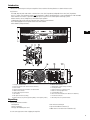
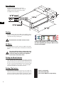
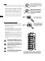
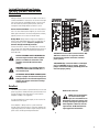
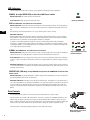
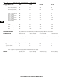
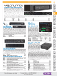
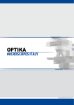
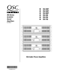
Installed Sound Professional Audio Amplifiers • • • • • • • ISA 280 ISA 450 ISA 750 ISA 1350 ISA 300Ti ISA 500Ti ISA 800Ti *TD-000136-00* TD-000136-00 Rev.C User Manual EN Manual del Usario ES Manuel de l’utilisateur FR Bedienhandbuch DE ⫼᠋ݠ CH Important Safety Precautions & Explanation of Symbols CAUTION: TO REDUCE THE RISK OF ELECTRIC SHOCK, DO NOT REMOVE THE COVER. NO USER-SERVICEABLE PARTS INSIDE. REFER SERVICING TO QUALIFIED PERSONNEL. EN The lightning flash with arrowhead symbol within an equilateral triangle is intended to alert the user to the presence of uninsulated “dangerous” voltage within the product's enclosure that may be of sufficient magnitude to constitute a risk of electric shock to humans. The exclamation point within an equilateral triangle is intended to alert the user to the presence of important operating and maintenance (servicing) instructions in this manual. The lightning flashes printed next to the OUTPUT terminals of the amplifier are intended to alert the user to the risk of hazardous energy. Output connectors that could pose a risk are marked with the lightning flash. Do not touch output terminals while amplifier power is on. Make all connections with amplifier turned off. WARNING: To prevent fire or electric shock, do not expose this equipment to rain or moisture. The appliance shall not be exposed to dripping or splashing and that no objects filled with liquids, such as vases, shall be placed on the apparatus. This amplifier has a serial number located on the rear panel. Please write this and the model number down and keep them for your records. Keep your purchase receipt. It is your proof of purchase. Serial Number:______________________________ Date of Purchase:____________________________ Purchased From:_____________________________ © Copyright 2003, 2004, QSC Audio Products, Inc. QSC® is a registered trademark of QSC Audio Products, Inc. “QSC” and the QSC logo are registered with the U.S. Patent and Trademark Office All trademarks are the property of their respective owners. 2 Introduction Thank you for purchasing this QSC power amplifier. Please read the following directions to obtain the best results. Key Features: •ISA 280, 450, 750, and 1350 models: 2 channels at 2 ohms (min.) impedance, bridgeable into 4 ohms (min.) impedance. •ISA “Ti” models: low impedance outputs and isolated 70V or 100V for distributed audio systems, bridgeable for 140V and 200V. •QSC DataPort V2 connects to optional QSC signal processing accessories and amplifier monitoring systems. •Mode switches Stereo, Bridge Mono, and Parallel Input operation. • Independent Clip Limiter and Low Frequency Filter settings for each channel. •ISA 1350 equipped with front panel Protect mode LED indicator. •QSC durability and performance. EN 1- Cooling Air Exhaust Vents 2- Power On Indicator (ISA 1350 has Protect LED also) 3- Power Switch 4- Clip and Signal Presence Indicators for each channel 5- DataPort V2 Connector 6- Terminal block input connectors 7- Gain Controls 8- XLR input Connectors (locking) 9- Mode Switches (Clip Limiter, Operating Mode, Low-Frequency Filters) 10- Mode Switch Settings 11- Bridge Mode Switch Settings and Notes 12- Cooling Air Intake 13- Output Connectors (Ti model shown) 14- Tabs for Securing Output Wires 15- Serial Number Decal 16- AC Power Circuit Breaker (ISA 1350 has two breakers) 17- IEC Power Connector 18- Mounting Holes for Optional Handles Unpacking Factory packed carton contains: • the amplifier • this User Manual • IEC-type detachable power cord • rear rack ear mounting kit • 3-pin terminal block connectors (2) • rubber feet for non-rack mount installations (4) Use the same type carton when shipping the amplifier. 3 Rack Mounting Use four screws and washers to mount the amplifier to the equipment rack rails. To use the amplifier outside a rack, attach the self-adhesive rubber feet to the bottom. EN Cooling Air flows from the rack, into the back of the amplifier, and out the front. This keeps the rack cool. The fan automatically runs faster when the amp is working hard. Do not block the rear intake or front air vents! AC Mains Air flow in QSC amplifiers: Cool air is drawn into the rear of the amplifier by the cooling fan. Warm air exits the front of the amplifier. Connect AC power to the IEC socket on the back of the amplifier. NOTE: Turn off the AC power switch before connecting AC power. The correct AC line voltage is shown on the serial number label, on the rear panel. Connecting to the wrong line voltage may damage the amplifier or increase the risk of electric shock. Setting the Mode Switches The rear panel mode switches control the amplifier’s operating mode, and each channel’s independent clip limiting and low frequency (LF) filtering. All models Clip Limiter switch settings are the same. However, Operating Mode and Low Frequency Filter settings are different for the Ti models. The rear panel label shows this information for convenient reference. Setting Clip Limiters Each channel has a clip limiter with its own on-off switch. The limiter only responds to actual clipping, and automatically compensates for load and voltage variations. Clip limiting is generally recommended, especially to protect high frequency drivers. 4 Switch 1 controls CH1. Switch 10 controls CH2. Set switch to RIGHT to use Clip Limiting. Selecting Stereo, Parallel, or Bridge Mode The amplifier can be set for normal Stereo mode, Parallel Input mode, or Bridge Mono mode. Stereo Mode- Each channel remains independent, and may be used for two different signals. Parallel Mode - This setting connects both inputs together. One signal feeds both channels. Each channel's Gain control and speaker connection remain independent. Bridge Mode- This setting combines both channels of a pair into a single channel with twice the output voltage. Use only the first channel's input and Gain control. Set the second channel's Gain control at minimum. The load must be rated for the higher power (or voltage) and is connected as shown on pages 6 and 7. Do not connect more than one input when operating in parallel or bridge mode. ISA 280/450/750/1350 ISA 300Ti/ 500Ti/800Ti Stereo Mode Switches 4, 5, 6 and 7 are all set to the LEFT position. Ti Stereo Mode Switches 3, 4, 5, 6, 7, and 8 are all set to the LEFT position. Parallel Mode Switches 4 and 5 are set to the RIGHT position. Switches 6 and 7 are set to the LEFT position. Ti Parallel Mode Switches 3, 4, and 5 are set to the RIGHT position. Switches 6, 7, and 8 are set to the LEFT position. Bridge ModeSwitches 4, 5, 6, 7, and 8 are all set to the RIGHT position. Switch 10 is set to the LEFT position. Ti Bridge ModeSwitches 3, 4, 5, 6, 7, and 8 are all set to the RIGHT position. Switch 10 is set to the LEFT position. Low Frequency FilterSwitches 2 and 3 control CH1. Switches 8 and 9 control CH2. Switches 3 and 8 turn the LF filter ON or OFF. Switches 2 and 9 select 30Hz or 70 Hz. Ti Low Frequency FilterSwitch 2 controls CH1. Switch 9 controls CH2. Switches 2 and 9 select 50Hz or 75 Hz. EN Setting Low Frequency Filters ISA 280, ISA 450, ISA 750 and ISA 1350: Use of the Low Frequency Filters is recommended. Use the appropriate switch settings to turn the filter ON or OFF and to select the filter frequency. When set to the ON position, the channel has a 12dB per octave Low Frequency filter to limit subaudio cone movement, making more power available for the loudspeaker’s rated frequency range. The filter should only be turned OFF for driving subwoofers. ISA 300Ti, ISA 500Ti, and ISA 800Ti: The Low Frequency Filters are always active and not defeatable. Each channel has a 12dB per octave Low Frequency filter to prevent saturation of the 70V loudspeaker transformers. This reduces distortion and prevents amplifier overload. The 50 Hz setting usually works well with high quality loudspeaker transformers. The 75 Hz setting works well with speech-grade loudspeakers and transformers. 5 Inputs Each channel has a balanced XLR and terminal block input. The input impedance is 20k ohm balanced or 10k ohm unbalanced. Balanced connections are recommended for less AC hum and interference, especially with long cable runs. Unbalanced connections may be suitable for short cables. The signal's source impedance should be less than 600 ohms. If the DataPort is being used to provide input signals to the amplifier, do not connect input signals to the XLR or terminal block connectors. EN Balanced Terminal Block inputs: Strip the wire ¼ inch (6 mm) and connect to the plug as shown. Be sure to tighten the screws firmly. Unbalanced Terminal Block inputs: Strip the wire ¼ inch and connect to the plug as shown. The middle pin must be connected to the shield pin as shown. Be sure to tighten the screws firmly. If unbalanced connection is necessary, connect the signal conductor to the connector’s + pin and the shield to the ground pin. Connect a jumper between the ground pin and the - pin. Balanced XLR inputs: Connect to the plug as shown. Direct Low Impedance Outputs Direct Low Impedance Output connections are shown on the back of the chassis, to the right of the output terminals. Carefully note the polarity marks, which are arranged to make Bridge Mode connections easier. Unbalanced XLR inputs: Connect to the plug as shown. The - pin must be connected to the shield pin as shown. Stereo and Parallel Mode- Connect each loudspeaker load to its own channel of the amplifier, as shown on the chassis label to the right of the terminals. The mode configuration switches, page 5, must be set for Stereo or Parallel mode. Bridge Mode- Bridge mode configures the amplifier to drive a single, high power loudspeaker load. See page 5 to set the Bridge Mode switches. Connect the load as shown on label to the right of the terminals. Use the center two terminals labelled BRIDGE MONO. 4 ohms is the minimum impedance in bridged mode. Use Stereo or Parallel mode channels to drive 2 ohm loads. BRIDGE MODE PRECAUTIONS: Do not use less than 4 ohm loads in bridge mode! 4 ohms is the minimum impedance for bridge mode operation. OUTPUT TERMINAL SAFETY WARNING! Do not touch output terminals while amplifier power is on. Make all connections with amplifier turned off. Risk of hazardous energy! WARNING! Risk of hazardous energy! Class 2 wiring shall be used. ISA 1350 WARNING!: Use proper speaker wire. Class 2 wiring shall be used. For bridged mono mode, Class 3 wiring shall be used. 6 Direct Low Impedance Outputs: Connect the loudspeakers as shown on the label next to the output terminals. Note Bridge Mono connection (center terminals) and polarity! Isolated Distributed Line Outputs: ISA 300Ti, ISA 500Ti, and ISA 800Ti Models Only Wiring connections are shown on the back of the chassis. STEREO and PARALLEL connections are shown on the right side of the terminals, and BRIDGE mode is shown on the left side. Carefully note the polarity marks, which are arranged to make Bridge Mode connections easier. Stereo and Parallel Mode- Connect each 70V/100V circuit to its own channel of the amplifier, as shown on the label, right of terminals. The mode configuration switches, page 6, must be set for Stereo or Parallel mode. Bridge Mode- Bridge mode configures the amplifier to drive a single 140V/200V audio circuit. See page 6 to set the Bridge Mode switches. Connect a jumper wire between CH1 [0] and CH2 [0] terminals. Connect the load as shown on the label, left of the terminals. Connect only 140V/200V distributed audio circuits in bridged mode. Use Stereo or Parallel mode channels to drive 70V loads. OUTPUT TERMINAL SAFETY WARNING! Do not touch output terminals while amplifier power is on. Make all connections with amplifier turned off. Risk of hazardous energy! WARNING! Class 2 wire shall be used. For isolated distributed 140V and 200V, Class 3 wire shall be used. EN 70V/100V Stereo or Parallel connection: Each 70V/ 100V zone connects to its respective channel. Ensure that all speaker connections maintain proper polarity. 140V/200V Bridge connection: Wire each bridged pair to a 140V/200V circuit as shown. Connect a jumper wire between CH1 [0] and CH2 [0] terminals. Check for proper polarity. ATTENTION! BRIDGE MODE CONNECTIONS: Connect a jumper wire between CH1 [0] and CH2 [0] terminals. The isolated output feature requires this jumper connection for bridge mode operation. DataPort The DataPort V2 connects to optional QSC accessories and processing devices. DataPort devices provide remote monitoring, DSP processing, filter and crossover functions. Amplifier Standby is not supported. If using the DataPort for input signals, do not use the Terminal Block or XLR inputs. If the amplifier is being used in a system monitored through a QSC cinema monitor (or other QSC DataPort V2 supporting product) CH1 and CH2 output voltages and AC power status will be reported by the DataPort. DataPort V2 connector. NOTE! If using the DataPort V2 connection for signal input, the unused XLR or terminal block connectors may be used for daisy chaining the input signal to other amplifiers. However, note the signal will be 10 dB down from the signal applied to the DataPort. 7 LED Indicators The LED indicators can be used to monitor system operation and identify common problems. POWER: A single GREEN LED, on left side of AC Power switch. Normal indication: AC switch ON: LED will illuminate. If no indication: Check AC power cord and AC outlet. Power on indicator. CLIP: Two RED LEDs, one indicator for each channel. EN Normal indication: illuminates whenever the amplifier is driven beyond full power. The resulting distortion corresponds to the brightness of the LED. Distortion that causes only brief flashing may not be audible. During muting, the LED fully illuminates. This occurs during normal “On-Off” muting. Abnormal indication: Bright red illumination while the amp is being used indicates either thermal muting or a shorted output. If the amplifier overheats, the fan will run at full speed, and operation should resume within one minute. Allow the fan to run, and make sure the amplifier ventilation is adequate. A shorted or overloaded output circuit will cause excessive Clip flashing and possible overheating. If distortion is audible without a Clip indication, the problem is either before or after the amplifier. Check for damaged speakers or overloaded signal source. The amplifier Gain control should be in the upper half of its range to prevent input overload. SIGNAL: Two GREEN LEDs, one indicator for each channel. Normal indication: illuminates when the input signal is strong enough to drive the output to -40 dB from rated 8 ohm power. As signal approaches full power, the LED will illuminate continuously. Clip and Signal indicators for both channels. If no indication: check Gain settings and increase gain if necessary. Check input connections and audio source for signal. If the Clip LED illuminates with little or no Signal indication, check the output wiring for shorts. Abnormal indication: If the Signal LED illuminates with no signal input, there may be system oscillations or some other malfunction. Disconnect the load and fully reduce the gain. If the signal LED remains on, the amp may need servicing. PROTECT (ISA 1350 only): A single RED LED directly below the POWER LED on left side of AC Power switch. Normal indication: not illuminated (NOTE!: If both rear panel AC circuit breakers are open, the PROTECT LED and the POWER ON LED will not illuminate) Abnormal indication: illuminated. If the PROTECT LED illuminates, the amplifier is in thermal protect or one of AC circuit breakers has opened. If the amplifier is hot, leave the AC power switch ON so that the fan cools the amplifier off. Normal operation will resume automatically after the amplifier has cooled sufficiently. If an AC circuit breaker (rear panel) has opened, reset the breaker by pushing inward on its reset button. Gain Controls Turn the gain controls clockwise to increase gain and counterclockwise to decrease gain. The Gain controls are marked in dB of attenuation. There are 11 detents for repeatable adjustments. The upper 6 steps are about 2 dB each, and settings should normally be made within this range. The range below -10 dB should not be used for normal program levels, as the input headroom could be exceeded, but can be used for testing at reduced levels. At the minimum setting, the signal is completely cut off. The Gain controls can be adjusted by grasping the control shaft and rotating. Gain controls are located on the rear panel. 8 Specifications (all models) DYNAMIC HEADROOM 2 dB at 4 ohms DISTORTION SMPTE-IM Less than 0.01% SIGNAL TO NOISE -100 dB (unweighted, 20 Hz.-20 kHz.) INPUT CLIPPING +22 dBu, 10 Vrms (ISA 1350: +15.3 dBu, 4.53 Vrms) INPUT IMPEDANCE 10k ohms unbalanced, 20k ohms balanced AMPLIFIER PROTECTION Short circuit, open circuit, thermal, ultrasonic and RF protection. Stable into reactive or mismatched loads. LOAD PROTECTION Turn-on/turnoff muting, AC coupling (DC fault blocking), Clip limiting. COOLING Continuously variable speed fan; back-to-front air flow through heat sink tunnel LED INDICATORS POWER (green), SIGNAL (green, 1 per channel) and CLIP (red, 1 per channel) ISA 1350: also equipped with Protect LED (red) CONNECTORS Input: (2) 3-pin terminal block and (2) XLR Output: screw terminal barrier strip Control & Monitoring: (1) QSC DataPort V2 POWER REQUIREMENTS Refer to voltage specified on rear panel serial number label. Configured at factory for 100, 120 or 230 VAC, 50- 60 Hz. CONTROLS & INDICATORS Front: AC POWER switch Back: gain controls, 10-position DIP switch block (Clip Limiters, Stereo/Parallel/Bridge mode selection, Low frequency filter on/off (low impedance models only), Low frequency filter selection of 30/70 Hertz (low impedance models) or 50/75 Hertz (Ti models), and AC circuit breaker (2 breakers on ISA 1350). DIMENSIONS 19.0" (48.3 cm) wide, 5.2" (13.2 cm) tall (3 rack spaces) 15.90" (40.4 cm) deep EN SPECIFICATIONS SUBJECT TO CHANGE WITHOUT NOTICE 9 Specifications: ISA 280, ISA 450, ISA 750, and ISA 1350 OUTPUT POWER in watts FTC: 8 ohms, 2 channels driven (20 Hz - 20 kHz, 0.1% THD) 4 ohms 2 channels driven (20 Hz - 20 kHz, 0.1% THD) ISA280 ISA 450 ISA 750 ISA 1350 185 260 450 800 280 400 650 1300 100 140 250 475 200 280 475 850 300 450 750 1400 430 700 1200 2000 370 520 900 1600 600 900 1500 2800 830 1400 2400 4000 EIA: 16 ohms, 1 channel driven (1 kHz, 0.1% THD) 8 ohms, 1 channel driven (1 kHz, 0.1% THD) 4 ohms, 1 channel driven (1 kHz, 0.1% THD) 2 ohms, 2 channels driven (1 kHz, 1.0% THD) EN Bridged Mono: 16 ohms (20 Hz - 20 kHz, 0.1% THD) 8 ohms (1 kHz, 0.1% THD) 4 ohms (1 kHz, 1.0% THD) FREQUENCY RESPONSE +0.0, -1.0 dB: 20 Hz to 20 kHz (LF filter OFF, at -10 dB from rated power), -3 dB points: 5 Hz and 50 kHz. DAMPING FACTOR >200 at 8 ohm load >200 at 8 ohm load >200 at 8 ohm load >250 at 8 ohm load INPUT SENSITIVITY +3.43 dBu (1.15 Vrms) +2.81 dBu (1.07 Vrms) +2.81 dBu (1.07 Vrms) +4.08 dBu (1.24 Vrms) VOLTAGE GAIN 30.5 dB (33.4 x) 33.0 dB (44.7 x) 35.0 dB (56.2 x) 36.1 dB (64.0x) OUTPUT CIRCUIT TYPE AB AB H 2-tier H 3-tier 0.6 4.0 6.3 9.2 1.3 6.2 9.9 14.0 47 pounds (25.0 kg) 68 pounds (30.8 kg) CURRENT CONSUMPTION (Ampere, rms, both channels driven, 120 VAC*) Idle 0.5 0.5 1/8 power**, 8 ohms 3.0 3.7 1/8 power**, 4 ohms 4.5 6.0 1/8 power**, 2 ohms 6.5 9.3 * NOTE: for 240 VAC models, multiply all values by 0.5 (one-half). ** NOTE: 1/8 power is representative of typical program material with occasional clipping. WEIGHT 36 pounds (20.0 kg) 36 pounds (20.0 kg) SPECIFICATIONS SUBJECT TO CHANGE WITHOUT NOTICE 10 Specifications: ISA 300Ti, ISA 500Ti, and ISA 800Ti OUTPUT POWER in watts FTC: 8 ohms, 2 channels driven (20 Hz - 20 kHz, 0.1% THD) 4 ohms 2 channels driven (20 Hz - 20 kHz, 0.1% THD) ISA 300Ti ISA 500Ti ISA 800Ti 185 260 450 280 400 650 100 140 250 200 280 475 300 450 750 430 700 1200 EIA: 16 ohms, 1 channel driven (1 kHz, 0.1% THD) 8 ohms, 1 channel driven (1 kHz, 0.1% THD) 4 ohms, 1 channel driven (1 kHz, 0.1% THD) 2 ohms, 2 channels driven (1 kHz, 1.0% THD) EN Bridged Mono: 16 ohms (20 Hz - 20 kHz, 0.1% THD) 8 ohms (1 kHz, 0.1% THD) 4 ohms (1 kHz, 1.0% THD) Distributed High Impedance (per channel): 70 Volt per channel (50 Hz - 16 kHz, 0.5% THD) 100 Volt per channel (50 Hz - 16 kHz, 0.5% THD) 140 Volt bridged, single channel (50 Hz - 16 kHz, 0.5% THD) 200 Volt bridged, single channel (50 Hz - 16 kHz, 0.5% THD) 370 520 900 600 900 1500 830 1400 2400 300 500 800 300 500 800 600 1000 1600 600 1000 1600 FREQUENCY RESPONSE Direct Outputs Isolated Outputs -3.0, -0.5 dB: 50 Hz to 20 kHz (LF filter 50 Hz, 10 dB from rated power) +0.0, -3.0: 50 Hz to 16 kHz (LF filter 50 Hz, at -10 dB from rated power) OUTPUT REGULATION 1.5 dB no-load to full-load INPUT SENSITIVITY Direct Low Impedance Outputs Isolated Distributed Line Outputs (Ti only) Full load, 70/100V +3.43 dBu (1.15 Vrms) +2.20 dBu (1.00) Vrms) +2.81 dBu (1.07 Vrms) +1.80 dBu (0.95 Vrms) +2.81 dBu (1.07 Vrms) +1.80 dBu (0.95 Vrms) VOLTAGE GAIN Direct Low Impedance Outputs 30.5 dB (33.4 x) 33.0 dB (44.7 x) 35.0 dB (56.2 x) OUTPUT CIRCUIT TYPE AB AB H 2-tier 0.5 3.7 6.0 9.3 6.9 0.6 4.0 6.3 9.2 8.5 44 pounds (20.0 kg) 55 pounds (25.0 kg) CURRENT CONSUMPTION (Ampere, rms, both channels driven, 120 VAC*) Idle 0.5 1/8 power**, 8 ohms 3.0 1/8 power**, 4 ohms 4.5 1/8 power**, 2 ohms 6.5 1/8 power**, 70V/100V 5.5 * NOTE: for 240 VAC models, multiply all values by 0.5 (one-half). ** NOTE: 1/8 power is representative of typical program material with occasional clipping. WEIGHT 44 pounds (20.0 kg) SPECIFICATIONS SUBJECT TO CHANGE WITHOUT NOTICE 11 Warranty Information & How To Contact QSC Warranty (USA only; other countries, see your dealer or distributor) Disclaimer QSC Audio Products, Inc. is not liable for any damage to speakers, or any other equipment that is caused by negligence or improper installation and/or use of this amplifier product. EN QSC Audio Products 3 Year Limited Warranty QSC Audio Products, Inc. (“QSC”) guarantees its products to be free from defective material and / or workmanship for a period of three (3) years from date of sale, and will replace defective parts and repair malfunctioning products under this warranty when the defect occurs under normal installation and use - provided the unit is returned to our factory or one of our authorized service stations via prepaid transportation with a copy of proof of purchase (i.e., sales receipt). This warranty provides that the examination of the return product must indicate, in our judgment, a manufacturing defect. This warranty does not extend to any product which has been subjected to misuse, neglect, accident, improper installation, or where the date code has been removed or defaced. QSC shall not be liable for incidental and/or consequential damages. This warranty gives you specific legal rights. This limited warranty is freely transferable during the term of the warranty period. Customer may have additional rights, which vary from state to state. In the event that this product was manufactured for export and sale outside of the United States or its territories, then this limited warranty shall not apply. Removal of the serial number on this product, or purchase of this product from an unauthorized dealer, will void this limited warranty. Periodically, this warranty is updated. To obtain the most recent version of QSC's warranty statement, please visit www.qscaudio.com. Contact us at 800-854-4079 or visit our website at www.qscaudio.com. How to Contact QSC Audio Products Mailing address: QSC Audio Products, Inc. 1675 MacArthur Boulevard Costa Mesa, CA 92626-1468 USA Telephone Numbers: Main Number (714) 754-6175 Sales & Marketing (714) 957-7100 or toll free (USA only) (800) 854-4079 Customer Service(714) 957-7150 or toll free (USA only) (800) 772-2834 Facsimile Numbers: Sales & Marketing FAX(714) 754-6174 Customer Service FAX(714) 754-6173 World Wide Web: www.qscaudio.com E-mail: [email protected] [email protected] QSC Audio Products, Inc. 1675 MacArthur Boulevard Costa Mesa, California 92626 USA “QSC” and the QSC logo are registered with the U.S. Patent and Trademark Office. ©2003, 2004 QSC Audio Products, Inc. 12