1
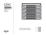
CX168 8-Channel Installed Sound Professional Audio Amplifier User Manual *TD-000095-00* TD-000095-00 rev.A 1 IMPORTANT SAFETY PRECAUTIONS & EXPLANATION OF SYMBOLS CAUTION RISK OF ELECTRIC SHOCK DO NOT OPEN CAUTION: TO REDUCE THE RISK OF ELECTRIC SHOCK, DO NOT REMOVE THE COVER. NO USER-SERVICEABLE PARTS INSIDE. REFER SERVICING TO QUALIFIED PERSONNEL. The lightning flash with arrowhead symbol within an equilateral triangle is intended to alert the user to the presence of uninsulated “dangerous” voltage within the product’s enclosure that may be of sufficient magnitude to constitute a risk of electric shock to humans. The exclamation point within an equilateral triangle is intended to alert the user to the presence of important operating and maintenance (servicing) instructions in this manual. The lightning flashes printed next to the OUTPUT terminals of all ISA amplifiers are intended to alert the user to the risk of hazardous energy. Output connectors that could pose a risk are marked with the lightning flash. Do not touch output terminals while amplifier power is on. Make all connections with amplifier turned off. WARNING: TO PREVENT FIRE OR ELECTRIC SHOCK, DO NOT EXPOSE THIS EQUIPMENT TO RAIN OR MOISTURE. This amplifier has a serial number located on the rear panel. Please write this and the model number down and keep them for your records. Model: CX168 Serial Number:______________________________ Date of Purchase:____________________________ Purchased From:_____________________________ FCC INTERFERENCE STATEMENT NOTE: This equipment has been tested and found to comply with the limits for a class B digital device, pursuant to part 15 of the FCC rules. These limits are designed to provide reasonable protection against harmful interference in a residential installation. This equipment generates, uses, and can radiate radio frequency energy and if not installed and used in accordance to the instructions, may cause harmful interference to radio communications. However, there is no guarantee that interference will not occur in a particular installation. If this equipment does cause harmful interference to radio or television reception, which can be determined by switching the equipment off and on, the user is encouraged to try to correct the interference by one or more of the following measures: - Reorient or relocate the receiving antenna. - Increase the separation between the equipment and the receiver. - Connect the equipment into an outlet on a circuit different from that to which the receiver is connected. - Consult the dealer or an experienced radio or TV technician for help. © Copyright 2001, QSC Audio Products, Inc. QSC® is a registered trademark of QSC Audio Products, Inc. “QSC” and the QSC logo are registered with the U.S. Patent and Trademark Office The Audio Precision logo is the property of Audio Precision, Beaverton OR All trademarks are the property of their respective owners. 2 TABLE OF CONTENTS INTRODUCTION: CX168 Overview .......................................................................................4 Front Panel Illustration .........................................................................................4 Rear Panel Illustration ........................................................................................5 Mounting Dimensions .........................................................................5 INSTALLATION: What is Included..............................................................................................6 Rack Mounting ....................................................................................6 Supporting the Rear of the Amplifier.....................................................6 Fan Cooling...........................................................................................7 AC Mains (AC Power) Connection..............................................................................7 SETUP: Setting the Configuration (MODE) Switches....................................................8 Setting Operating Mode (Stereo, Parallel, or Bridge)........................................9 Clip Limiter Setting.............................................................................10 Low Frequency (Subaudio) Filter Settings................................................................10 Low Frequency Filtering Tips and CX168 Frequency Response Curve...................11 CONNECTIONS: Inputs: Connecting to the Input Terminal Block Inputs ...................................12 Connecting to the DataPort Inputs.......................................................13 Outputs: Connecting the Outputs in Stereo or in Bridge Mode .........................14 How to use the 8-pin Output Connectors................................15 OPERATION: Power Switch ............................................................................................16 LED Indicators .......................................................................................17 Gain Controls ......................................................................................18 Security Plate for Gain Controls .........................................................19 DataPort Connector ...................................................................................20 DataPort Guidelines for the CX168.........................................21 APPLICATIONS: Four Room, Stereo Feed..............................................................................................22 Tri-Amplified, Stereo Cabinets with Subwoofer..............................................22 APPENDIX: Detailed Explanation of Stereo, Parallel, and Bridge Operating Modes..........24 Multiple Speaker Loads in Series........................................................26 Multiple Speaker Loads in Parallel........................................................27 TROUBLESHOOTING ........................................................................................................28 SPECIFICATIONS ......................................................................................................30 WARRANTY INFORMATION .............................................................................................32 HOW TO CONTACT QSC AUDIO PRODUCTS ............................................................................32 3 INTRODUCTION Congratulations on your purchase of the CX168 power amplifier. To help you obtain the best results from your purchase, we encourage you to carefully review this manual. With information including connections, configuration and operation, it offers many useful guidelines. Alternatively, these DataPorts facilitate connection of signal processing equipment, such as QSC’s DSP-3, which offers two channels of independent digital signal processing - including crossover filters, shelf filters, signal delay, compression, peak limiting, and parametric filters. The CX168 provides a high level of channel density in a small, lightweight form factor ideal for multi-zone audio systems. Representing the culmination of QSC’s extensive experience in power amplifier development, the CX168 is a highly versatile, reliable, and user-friendly tool that will likely remain a central component of your system for years to come. As individual channel pairs may be bridged, the CX168 is configurable as a 4-, 5-, 6-, 7-, or 8-channel unit. Further, the CX168 features detachable Phoenix-style input and output connectors—enabling the audio system to be wired with greater ease. Other features include 1-dB recessed and detented gain controls and a security cover for tamper-proof installations. Like the entire CX Series, the CX168 is equipped with QSC’s exclusive PowerWaveTM switching power supply technology to virtually eliminate noise and hum while reducing the unit’s overall weight. Comprehensive protection circuitry includes DC, infrasonic, thermal overload and short circuit protection. The CX168 includes 4 HD15 DataPorts (one per channel pair) for remote management or DSP. These ports allow each channel pair to be governed by QSControl, QSC’s audio networking system—enabling the system operator to control amplifier gain levels, check the unit’s clipping and thermal status, plus monitor numerous additional system parameters. FRONT PANEL FRONT PANEL WITH SECURITY PLATE 4 The CX168 is easy to use. All operating mode switches are grouped together on the rear panel, with one switchblock per channel pair. These switches enable clip limiter on/off, LF filter on/off, LF filter select and operation modes. The amplifier’s front panel includes corresponding LEDs to indicate Bridged or Parallel modes in addition to Signal and Clip status. Your CX168 power amplifier was designed to provide many years of trouble-free, great-sounding operation. We hope you enjoy your new CX168. INTRODUCTION REAR PANEL DIMENSIONS AND MOUNTING POINTS 5 INSTALLATION: UNPACKING & RACK MOUNTING What is Included Your CX168 shipping container, as shipped from the factory, includes: - CX168 eight channel audio power amplifier - this user’s manual - security cover (plate) for gain controls - self-adhesive rubber feet (use for non-rack mount applications) - eight 3-pin terminal block input connectors - two 8-pin terminal block output connectors - #14AWG IEC-type detachable power cord Save the container and packing material so the amplifier may be shipped without damage if service is ever required. If the original container is not available, be sure to use a strong shipping container with enough packing material to prevent the amplifier from being damaged in transit. Rack Mounting Use four screws and washers to secure the amplifier to the equipment rack rails. Support the weight of the amplifier while securing it to the rails to avoid bending or distorting the mounting ears. The amplifier may be used in an equipment rack or as a stand-alone unit. Rack mounting is optional. Self-adhesive rubber feet are provided for non-rack mount applications. Supporting the Rear of the Amplifier Unless the amplifier is being installed in its final, fixed location, we strongly recommend supporting the rear of the amplifier. Supporting the rear of the amplifier is required for mobile and portable use. If the amplifier is to be transported in any way, install the optional rear rack mounting ear kit to support the rear of the amplifier. During transport, the shock loads encountered on the chassis and rack can easily damage an unsupported amplifier and the rack rails. With proper support, reliability is enhanced. Rear rack mounting ear kits are an accessory item and are available from QSC’s Technical Services Department or from your dealer or distributor. Refer to the literature included with the rack mounting ear kit for installation instructions. Two methods of rear rack mounting ear attachment are possible; use the method that best suits you application. 6 Optional rear rack mounting ear attachment methodsrefer to the rear rack mounting ear kit’s documentation for details INSTALLATION: COOLING & AC MAINS REQUIREMENTS Fan Cooling The CX168 amplifier draws cool air into the rear of the amplifier and exhausts hot air from the front. This is done so the equipment in the rack stays as cool as possible. This method of cooling gives the operator “direct” air temperature feedback at the front of the rack, where it is the most convenient. The front panel’s temperature indicates “how hard” the amplifier is working. The fan varies speed automatically to maintain safe internal temperatures and minimize noise. Keep the front and rear vents clear to allow full air flow. Air flow in QSC amplifiers Do not obstruct the front or rear air vents! Make sure that plenty of cool air can enter the rack, especially if there are other units which exhaust hot air into it. AC Mains Connection The correct AC line voltage is shown on the serial number label. Make sure the AC mains is the correct voltage. Connecting to the wrong line voltage is dangerous and may damage the amplifier. Connect the AC line cord by orienting the IEC plug correctly and pushing the plug firmly into the IEC receptacle. It should seat tightly. It can only be inserted when it is properly oriented. Use the cord supplied with the amplifier, or an equivalent. Insure that the wire gauge of the cord is #14AWG. Use of #16 or #18 AWG can be dangerous and is not recommended. Use the best possible connection to the AC power source. Avoid extension cords as they will cause some voltage drop between the AC source and you amplifier. If the use of an extension cord is required, ensure that it is the shortest length possible and is at least #14 AWG. Ensure that all grounding connections are maintained. The correct AC line voltage is shown on the serial number label. Connecting to the wrong line voltage is dangerous and may damage the amplifier or constitute the risk of electric shock. Verify the correct AC line voltage by checking the specification printed on the serial number label on the rear panel. NOTE: Excessive length or inadequate gauge may result in short muting episodes if all channels are driven to full power. 7 SETUP: SETTING THE MODE CONFIGURATION DIP SWITCHES Setup By using the mode switches and connecting to the amplifier properly, the CX168 amplifier can be configured as a 1 to 8 channel amplifier. This flexibility enables the CX168 to be used for most any multichannel application. The CX168 can be thought of as four separate 2-channel amplifiers on one chassis. Each of the four amplifier sections may be operated in Stereo, Parallel, or Bridge mode independently of the others. For example, channels 1 & 2 could be set for stereo operation while channels 3 & 4 are set for parallel operation; all while channels 5 & 6 and channels 7 & 8 are set for bridge mode. The channels are grouped as follows: Channels 1 and 2 Channels 3 and 4 Channels 5 and 6 Channels 7 and 8 You can set the operating mode for each group by setting that group’s configuration DIP switches in the desired positions. It is NOT POSSIBLE to group the channels differently. For instance, you can not bridge channels 3 & 5 because they are not in the same channel group. Before setting the configuration DIP switches, you must first decide how the amplifier will connect to the speaker system. “MODE” configuration DIP switches are located on the rear panel and look like the illustration above. Switch positions shown are for example only. Set switches as required for your application. “MODE” switch settings and speaker connection diagrams are printed on a rear panel label, as shown, above. 8 SETUP: SETTING THE MODE: STEREO, PARALLEL, OR BRIDGE Modes The following descriptions apply to a channel pair (such as Ch. 1 & 2 or Ch. 7 & 8). It is possible to set each channel pair’s mode differently and customize the system configuration. All possible combinations will not be shown. The following describes the behavior of one channel pair in the three modes of operation and the BRDG and PAR LED’s: Stereo- Stereo mode supports two completely separate audio channels, usually referred to as ‘left’ and ‘right’. Stereo configurations have two separate input signals and two separate output signals. Mode switch settings and LED indication for stereo mode operation. BRDG and PAR indicators should not be illuminated when in stereo mode. Parallel- Parallel mode applies one input signal to both channels. Both inputs of a channel pair are connected in parallel when the mode switch is set for parallel, therefore, connect only one input per channel pair when in parallel mode. The outputs are connected the same as stereo mode. Each speaker will be supplied the same signal, which is still controlled by that channel’s gain control. Mode switch settings and LED indication for parallel mode operation. PAR indicator should be illuminated and BRDG indicator should not be illuminated when in parallel mode. Bridge- Bridge mode combines the two channels of a pair (such as Ch. 3 & Ch. 4) into one higherpowered channel. Like parallel mode, both inputs of a channel pair are connected in parallel when the mode switch is set for parallel, therefore, connect only one input per channel pair when in bridge mode. There are 4 possible channel pairs that can be bridged on the CX168. They are Ch.1-2 Bridge, Ch. 3-4 Bridge, Ch. 5-6 Bridge, and Ch. 7-8 Bridge. Any pair or number of pairs can be independently configured in bridge mode. Use the first channel’s input and gain control when in bridge mode. The second channel’s gain control is non-operative and should be turned all the way down. Mode switch settings and LED indication for parallel mode operation. BRDG indicator and PAR indicator should be illuminated when in bridge mode. Note! Do not connect more than one input per channel pair when operating in parallel or bridge mode. However, in parallel or bridge mode, the unused input terminals may be used for daisy-chaining the input signal to other channels of the CX168 or to other amplifiers. For pictorial description of operating modes, see Appendix. 9 SETUP: MODE SWITCHES: CLIP LIMITER AND LOW FREQUENCY FILTERS Clip Limiter The CX168 amplifier has separate clip limiters for each of the 8 channels. These clip limiters respond only to actual amplifier clipping. Amplifier clipping generates internal error signals which cause the clip limiter to quickly reduce gain and minimize the overdrive. To preserve as much of the program dynamics as possible, limiting occurs only during actual clipping. Each channel’s clip limiter can be switched on or off individually. The clip limiter is internally set to respond as fast as possible after clipping is detected. For program material that is primarily “full-range”, the effect on the overall audio quality should be imperceptible. We recommend using the clip limiters for almost all applications, especially full-range audio applications. Clipping can cause high-frequency artifacts to be output to the speakers, potentially damaging fragile high-frequency drivers. For program material that is primarily low-frequency in nature (low-frequency or subwoofer drive) this may be perceived as a “rubbery” effect on the audio. If this is the case, it may be preferable to turn the clip limiters off and let the amplifier clip occasionally. With robust, low-frequency drivers, the occasional clipping should cause no problems. Low Frequency Filter When driving speakers with limited low frequency response, it is important to limit the low frequency response of the amplifier. Doing so can result in more usable bass response since the speaker is not being overloaded by very low frequencies it can’t handle. Explanation- Low frequency sound waves require much more speaker cone motion to produce the same apparent loudness as higher frequencies. Properly designed speaker enclosures help the speaker to move more air with less motion using techniques like porting. Such enclosures only benefit from porting down to a certain frequency. Below this frequency, the speaker is “unloaded” and is basically free to move around uncontrollably without producing much bass. Limiting the frequency range of the low frequency content enables the speaker to behave the way it was designed to. If frequencies lower than designed are supplied to the speaker, performance will degrade. All low frequency filters will change the character of low frequency transients. For best results, the cabinet design, speaker capabilities, and program material must be taken into account when configuring low frequency filtering. 10 CAUTION! Clip limiting reduces extreme overdrive peaks, allowing a higher average signal level without distortion. Increasing the gain with the clip limiter engaged until clipping is again audible, can double the average output power. Be careful not to exceed the power rating of the speakers! SETUP: MODE SWITCHES: CLIP LIMITER AND LOW FREQUENCY FILTERS Low Frequency Filtering Tips: The OFF position should be used only for subwoofer systems with rated frequency response below 33 Hz. or if low frequency filtering is provided by other devices. Know the specification of the speaker cabinet you are driving. Match the low frequency roll off setting to the specified low frequency capability of the speaker cabinet. Do not drive the speaker with frequencies below its rating. Unless you have low frequency filtering before the amplifier, use the low frequency filter to protect your loudspeakers from cone over-excursion caused by frequencies below the speaker’s limits. The 33 Hz. rolloff is a good “all purpose” setting. Turn the filter on by setting the appropriate DIP switch to ON position and select 33 Hz. using its 33/70 Hz. DIP switch. This setting is a good starting point for most large, full-range cabinets. The 70 Hz. rolloff is a good setting to use with smaller, compact speaker cabinets having limited bass capability. Turn the filter ON and select the 70 Hz. setting when using smaller cabinets. The frequency selection ( 33 or 70 Hertz) has no effect unless the filter is set to the ON position. Frequency Response Curves Filter ON , 70 Hz. off Filter ON, 33 Hz. Filter 11 CONNECTIONS: INPUTS- Using the Terminal Block Inputs Each channel has an active balanced "Euro-style" terminal block input jack. These terminal blocks allow the input wiring to be terminated using simple hand tools and allows for quick reconfiguration when needed. The input impedance is 20k ohm balanced or 10k ohm unbalanced. Balanced connection is recommended for all audio inputs. Balanced signals are less prone to AC hum and other electrical noise. Unbalanced signals can be suitable for short cable runs. The signal source's output impedance should be less than 600 ohms to avoid high frequency loss in long cables. If the DataPort is being used for the input signal source, the terminal block connections should not be used for inputs. However, they may be used for daisy chaining the DataPort input signal to other channels or amplifiers. The signal available from the terminal block input connections will be about 10 dB lower than the signal presented to the DataPort. TERMINAL BLOCK CONNECTORS Terminal Block Connectors: Balanced inputs: Connect the conductors to the connector as shown. shield Terminal block: balanced connections Unbalanced inputs: Connect the conductors to the connector as shown. Make sure that the unused side of the balanced input is connected to ground, as shown. jumper shield Terminal block: unbalanced connections 12 CONNECTIONS: INPUTS- Using the DataPorts If used, the DataPort must be connected to a QSC DataPort product using a QSC DataPort cable. Do not use computer cables; they look similar but can cause operational problems with your amplifier and/or DataPort accessories. DATAPORT CONNECTORS The CX168 amplifier is equipped with four QSC DataPort connections that may be used for connecting to accessory QSC DataPort devices. Each DataPort services a specific channel pair; the channels are paired as: Ch. 1 and Ch. 2 Ch. 3 and Ch. 4 Ch. 5 and Ch. 6 Ch. 7 and Ch. 8 Each DataPort and its associated terminal block input pair can be configured independently (there is no requirement to use a DataPort connection for all channels). Only the Ch.1-Ch.2 DataPort can control the power supply standby mode. The DataPort connection will supply the input signals to the amplifier. If using the DataPort connection for audio input signals, do not apply inputs to the terminal block input connectors. If the DataPort connection is used only for monitoring amplifier operating conditions and NOT for providing audio inputs to the amplifier, then the terminal block inputs may be used to supply the audio inputs to the amplifier. How to Connect to the DataPort: Direct mounting of DataPort accessories is NOT supported by the CX168 amplifier. Devices that are normally mounted directly to the amplifier must be mounted remotely and connected to the DataPort using a DataPort cable. This is due to the high density of connectors on an eight-channel amplifier; there is not enough space to allow for accessories to be mounted directly to the back of the amplifier. If the accessory attaches with a QSC DataPort cable, orient the HD-15 male plug correctly with the DataPort socket on the amplifier (it is “D” shaped and will fit only one way). Push the plug onto the socket firmly and ensure it is seated properly. Finger-tighten the 2 retaining screws. Do not over tighten. Basic DataPort Notes: 1- The amplifier Gain controls will need to be set at their anticipated high-level setting. Use reduced level setting during setup & test. 2- If using the DataPort for audio input signals, control of the audio level will be accomplished with the DataPort accessory device to which the amp is connected. 3- Control of the amplifier’s AC power standby mode will only be possible via the Ch.1-2 DataPort. The amplifier’s POWER switch must be physically set to the “ON” position to use the standby control feature. 4- The order in which the four DataPorts are connected to external devices makes no difference to the amplifier. However, the host controller to which the amplifier is connected will show the channels in the order that cables are connected. 13 CONNECTIONS: OUTPUTS Outputs Refer to the label on the rear panel of the amplifier for proper wiring connections. The output connection for STEREO and PARALLEL modes is on the left side of the label , while the output connection for BRIDGE mode is shown to the right side of the label. Note: Polarity changes from channel to channel and is different for bridge mode. Be certain of polarity of connections before applying power. Reversed polarity may degrade audio frequency response. Speaker connection diagrams and “MODE” switch settings are printed on a rear panel label, as shown, above. Stereo and Parallel Mode In stereo or parallel mode, each speaker is connected to its own individual channel of the amplifier. This connection method is shown on the left side of the connection diagram (rear panel) or in the diagram, right. Use 4 ohm minimum impedance in stereo or parallel mode. Ensure the mode configuration switches are set for stereo or parallel mode when connecting speakers to each channel’s output. Bridge Mode Stereo or parallel connection- single speaker shown connected to amplifier channel 6 output. Ensure that all speaker connections maintain proper polarity ( + to +, - to - ). In bridge mode, each speaker is connected to a bridged-pair of outputs. The channels must first be “bridged” by setting the mode configuration switches to the bridge settings. Then connect the speakers as shown on the right side of the connection diagram (rear panel) or in the diagram, right. Use 8 ohm minimum impedance in bridged mode. Ensure the mode configuration switches are set for bridge mode when connecting speakers to bridged output pairs . BRIDGE MODE PRECAUTIONS: Do not use 2 ohm or 4 ohm loads in bridge mode! 8 ohms is the minimum impedance for bridge mode operation. This mode puts a high demand on the amplifier and speaker. Excessive clipping may cause protective muting or speaker damage. Ensure the speaker has a sufficient power rating. 14 Bridge connection- single speaker shown connected to amplifier channels 5 and 6 (bridged with mode switch settings). Ensure that all speaker connections maintain proper polarity ( + to +, - to - ). CONNECTIONS: OUTPUTS- USING THE TERMINAL BLOCK CONNECTORS OUTPUT TERMINAL SAFETY WARNING! Do not touch output terminals while amplifier power is on. Make all connections with amplifier turned off. Risk of hazardous energy! When selecting speaker cable (wire), always use the largest wire size and shortest length of wire practical for an installation. Larger wire sizes and shorter lengths minimize power loss and degradation of damping factor. Do not place speaker cables next to input wiring. Terminal Block Connections The output connections are made by attaching speaker wires to the 8-pin terminal block connectors. Once these connectors have been “populated” with the necessary speaker wire connections, plug the terminal blocks into their respective output jack. The output jacks are configured in two discrete connectors. One connector carries the connections for channels 1 through 4. The other, channels 5 through 8. Each connector has 8 pins, each of which connects to the speaker wire using a screw-clamp. Refer to the diagram, right, for the basic connection procedure. Be sure that speaker polarity is maintained. The locations of the “+” and “-” terminals on the amplifier is not the same for each channel. Ensure that all wires are neatly terminated with no loose strands. Do not strip the insulation back excessively. Loose strands and exposed wire beyond the terminals may cause a short circuit and cause protective muting of the amplifier. Once all the required connections have been made to the terminal block connectors, they may be inserted into the OUTPUTS jack on the rear panel. Orient the connector properly (it only fits one way) and push it in until it is fully seated in the receptacle. Note each connector is oriented so its wires face outwards. How to make connections to the terminal block: 1- Strip the wires approximately 0.28” (7mm). 2- Twist any loose strands of wire together. 3- Loosen the appropriate retaining screw fully. 4- Insert the stripped wire into the receptacle. 5- Tighten the appropriate retaining screw to secure. 15 OPERATION: POWER SWITCH and GAIN CONTROLS Power Switch The power switch is a rocker-type switch. It is located on the left side of the front panel. To turn the amplifier on, push in on the top of the switch. To turn the amplifier off, push in on the bottom of the switch. The green power LED should light up when the switch is in the on position. When the power is switched off, the LED may takes several seconds to go out; this is normal. To turn the amplifier ‘on’, push in on the top portion of the rocker switch firmly. It should move inward and snap into the ‘on’ position. After switching on, the power LED should illuminate. To turn the amplifier ‘off’, push in on the bottom portion of the rocker switch firmly. It should move inward and snap into the ‘off’ position. After switching off, the power LED should extinguish. If the POWER LED fails to illuminate when the switch is in the ON position: 1- Check the AC cord and insure that both ends are fully inserted into their receptacles. If the power LED still fails to illuminate, 2- Check the AC outlet for voltage with a circuit tester or known good device (lamp, etc.). 3- Make sure that the amplifier is not in STANDBY mode. If the amplifier is being controlled by one of its DataPort connectors, the amplifier may be in standby mode. Verify the AC power status from the DataPort device controlling the amplifier. 16 The ‘POWER’ LED is located at the upper-left of the gain controls section of the front panel. It is a green LED that illuminates when the power is turned on (and the amplifier is properly connected to the correct AC source). The power LED extinguishes when the power is turned off. OPERATION: LED INDICATORS LED Indicators The LED indicators provide basic operation information to the operator. The ‘normal’ indications of the LED’s are shown, below. NOTE! The BRDG and PAR mode indicator LED’s are discussed on page 9. POWER: The power ‘on’ indicator LED is located at the upper-left of the gain control cluster. It is green and illuminates when the power switch is set to the on position and AC power is present at the IEC cord receptacle. If no indication: Check AC power cord, AC mains, and that the DataPort is not being used to force the amplifier into ‘Standby’ mode. When power is switched off: the LED may take several seconds to extinguish (go out); this is normal. Normal indication: at power-on the LED will illuminate. SIGNAL: Each channel has a green ‘signal’ LED located to the right of its gain control. The ‘signal’ LED lights up when the input signal is sufficiently strong. Normal indication: illuminates when the input signal is present and sufficiently strong. If no indication: check gain settings, input cables, connections and audio source. If audio source is extremely low signal strength, signal LED may not illuminate; this is normal but indicates that the input signal strength should be increased. Occasional illumination: normal for weak input signal strength. Fully illuminated (on): normal. CLIP : Each channel has a red ‘clip’ LED that illuminates when the channel clips. It is located to the upperright of each channel’s gain control. Normal indication: illuminates briefly at extreme output power peaks. Occasional clipping at high power levels may be normal. At power-on, the clip LEDs may briefly flash during turn-on muting. Continuous operation at high power may trigger the thermal protection circuitry, shutting down the amplifier and fully illuminating the clip LED. Operation will resume after the amplifier has cooled down sufficiently. If no indication: normal if the amplifier is operated at nominal output levels. If the input signal is weak, it may not be capable of driving the amplifier into clipping, even at full gain. Occasional illumination: Occasional clipping (once briefly every few seconds) when operation at high power levels does not indicate trouble. Continuous operation at high power may trigger the thermal protection circuitry, shutting down the amplifier and fully illuminating the clip LED. Illuminated most of the time: Not normal; for cleaner sound, reduce the output of the amplifier and/or input signal to avoid thermal shutdown of the amplifier and possible speaker damage. If clipping persists at normal levels, check for shorted or abnormal load impedances. Fully illuminated (on): Amplifier is in thermal shut down. Reduce gain settings or input signal and allow the amp to cool down. Leave the power on so that the fan continues to run; operation will automatically resume after the amplifier has cooled sufficiently. 17 OPERATION: GAIN CONTROLS Gain Controls The gain controls are located on the right side of the front panel. They are operated by rotating the control clockwise to increase gain or counterclockwise to decrease gain. When turned fully counterclockwise, gain is fully reduced and no output signal will be present. When turned fully clockwise, the voltage gain of the amplifier is +26dB and the output signal will potentially be full strength (provided the input is fully driven). The gain controls are detented in 21 steps for repeatable adjustment. Surrounding the Gain control, the power attenuation level is shown in dB. Each detent is approximately 1dB change in amplifier gain. Location of gain controls on the front panel of the CX168 To operate the gain control, rotate the control’s knob so that the desired level is achieved. A small, flat-tipped screwdriver (#1 blade size) is typically used. Be sure not to use large screwdrivers as it is possible to damage the gain control by applying excessive torque. Gain controls are sensitive, electronic components and should be treated with care. Each channel pair’s gain controls and indicator LED’s are grouped together as shown, right. The channels are paired in the following manner: Channel Pair #1Channel Pair #2Channel Pair #3Channel Pair #4- Ch. 1 and Ch. 2 Ch. 3 and Ch. 4 Ch. 5 and Ch. 6 Ch. 7 and Ch. 8 As detailed in the ‘Setup’ section of this manual, channels can only be paralleled and bridged within their channel pair. Example- Channel 3 can be bridged with channel 4 only; it can not be bridged with any other channel. Typical channel-pair control and indicator group on the CX168 The dB markings around the gain controls are attenuation. They show attenuation from full gain. At 0db attenuation, the voltage gain of the amplifier is 26dB. If the gain control is set at the 7dB attenuation position, then the voltage gain of the amplifier is 19dB (26dB - 7 dB). Typical gain control showing attenuation level markings and LED’s for the channel. Note that there is only one BRDG (bridge) and one PAR (parallel) indicator per channel pair. 18 OPERATION: GAIN CONTROL SECURITY PLATE Gain Control Security Plate After final gain adjustments have been made, the gain controls can be covered with a security plate. This easy-to-use security plate makes it difficult for others to adjust the gain. This may be desirable in instances where the gain controls should not be tampered with. To install the security plate: 3. Line up the tabs with the keyed portion of the 1. Use a 9/64” or 3.5mm hex key to loosen ventilation slots, insert into the slot and then slide the panel fully right, locking it in the slot. the screw. Do not remove; just loosen several turns. 2. Orient the panel as shown and slide the right end 4. Make sure the LED’s are visible, then tighten the of the plate under the screw. screw with the hex key. Do not over tighten! When properly installed, the security panel will still allow you to monitor all the channel status LED’s and power LED. The amplifier front panel will look like the illustration, right, after installing the security plate. 19 OPERATION: USING THE QSC DATAPORT CONNECTIONS DataPort Connectors QSC’s DataPort equipped amplifiers offer operators of larger audio systems a high degree of system monitoring and operation from remote locations. A system operator in a sports complex might be located hundreds of yards (meters) from the actual amplifiers, making ‘normal’ control and monitoring of the system difficult, at best. By integrating QSC’s DataPort-equipped amplifiers with QSC’s DataPort accessories, a dependable and robust control and monitoring solution can easily be implemented. The DataPort is used for connection to optional QSC DataPort accessories. DataPort accessory devices can provide remote cinema monitoring, DSP, filter and crossover functions. The DataPort connections on the CX168 offer full-featured implementation of DataPort accessories and supply the required accessory voltage to DataPort devices that require it. CX168 amplifiers DO NOT support direct mounting of smaller accessories, like the DSP-3, due to the high density of connectors on the rear panel but they may be connected via cables. A single DataPort is assigned to each channel pair. Each DataPort is marked with the channel numbers served by that DataPort. Note, above, that each DataPort is clearly labeled and is located between its respective channel’s terminal block connectors. Using the DataPort Use a QSC DataPort cable to connect the CX168 DataPorts to DataPort accessories. Consult the accessory’s documentation for recommended mounting and interconnect information. Do not use terminal block connections for inputs when the DataPort is used as the input signal source. If you do, the signals from the DataPort and terminal block inputs will be mixed, possibly with unexpected results. See the following section for general operating notes regarding the DataPorts on the CX168. Connect to the DataPort using a QSC DataPort cable. Align the connector with the socket housing and insert fully. Finger-tighten the retaining screws. 20 OPERATION: USING THE QSC DATAPORT CONNECTIONS What Can I Connect to the DataPort? Consult your QSC representative for up-to-date accessory compatibility. QSC has several DataPort-based accessories available like the: CM16a Amplifier Controller & Monitor DSP-3 Digital Signal Processing Module DSP -30 Digital Signal Processor XC-3 Crossover SF-3 Subwoofer Filter LF-3 Low Frequency Filter DCM Crossovers & Monitors General Guidelines to using the DataPorts on the CX168 1. Each channel pair ( Ch.1-2, Ch.3-4, Ch.5-6, and Ch.7-8) has its own dedicated DataPort connector that applies control and monitoring functions to its specific channel pair. 2. The DataPort for channels 1 and 2 has a special function on the CX168. It is the ‘master’ DataPort for controlling AND reporting power supply status of the amplifier. It is only possible to control and report the status of the power supply using the Ch.1 & Ch.2 DataPort. 3. In order for the Ch.1 & Ch.2 DataPort to control the power status of the amplifier, the front-panel power switch MUST be in the ON position. If the power switch is in the ‘off’ position, the amplifier will not respond to any commands sent to its Ch.1 & Ch.2 DataPort. 4. The DataPort connection can be used for amplifier status monitoring only, using the terminal block inputs for supplying input signals to the amplifier. Ensure that the DataPort connection supplies NO INPUT SIGNAL when operating in this fashion. If signal is applied to both the DataPort and the terminal block input connector at the same time, the signals will be summed and amplified. The result may be undesirable. 5. If using the DataPort for supplying the audio input signals to the amplifier, we don’t recommend using the terminal block input connectors, even if they are connected to non-operating audio sources. The DataPort and terminal block inputs are connected in parallel and isolated by about 20k ohms of resistance. Even with this isolation, it is possible that connection to other signal sources may significantly alter the input impedance at the DataPort. This could affect output levels as connections are altered. 6. If using the DataPort for supplying the audio input signals to the amplifier, do not use the unused terminal block inputs for daisy-chaining the DataPort signals to other channel pairs or other amplifiers. The DataPort device supplying the audio signal will not accurately report gain and levels will be effected. 7. The heat sink temperatures of the CX168 are reported on the first channel of each channel pair’s DataPort. In other words, to monitor all four heat sink temperatures, all four DataPorts must be connected to the monitoring device (such as QSC’s CM16a). Temperatures will be reported on channels 1, 3, 5 and 7. 21 APPLICATIONS: TYPICAL APPLICATION EXAMPLES Four Room Stereo Feed A simple application of the CX168 would be an installation with 4 rooms of coverage; each room to be provided with a stereo audio feed. All speakers are 4 ohm or greater impedance and have a frequency response rated down to 45 Hz., making them suitable for the 70 Hz. low frequency setting. Clip limiting will be used with these full-range speakers. Operating mode of all four channel pairs will be set to ‘stereo’ because the audio inputs are stereo and a stereo result is desired in each room. Input connections can vary too much to provide meaningful examples. For this example, assume that each input has its own discrete signal provided at the terminal block input connectors. Routing would make sense if kept in room number order: Room #1: Room #2: Room #3: Room #4: Fed by channel pair #1 (Ch.1&2) Fed by channel pair #2 (Ch.3&4) Fed by channel pair #3 (Ch.5&6) Fed by channel pair #4 (Ch.7&8) MODE switch configuration: Ch.1/ Ch.2 mode switch: Clip Limiters ON Low Frequency Filter ON Low Frequency Setting 70 Hz. Mode: stereo Ch.3/Ch.4 mode switch: Ch.5/Ch.6 mode switch: Ch.7/Ch.8 mode switch: same as first mode switch same as first mode switch same as first mode switch Tri-Amp’d Stereo Cabinets with Subwoofer Driven by Bridged Channel Pair (next page) Two discrete 3-way (tri-amp) cabinets are to be connected to the CX168 along with an 8 ohm subwoofer cabinet. The subwoofer will require the most amount of power and therefore will be driven by two channels bridged into one. Its impedance meets the minimum requirement for bridged output. All other drivers are 4 ohms or greater and meet the single channel minimum impedance requirement. Each of the tri-amp cabinets will be driven with three discrete channels (totaling 6 channels). The total required channel count is 8; the CX168 is the perfect tool for the job. 22 APPLICATIONS: TYPICAL APPLICATION EXAMPLES Tri-Amp’d Stereo Cabinets with Subwoofer Driven by Bridged Channel Pair (continued) Routing is a function of ‘easiest wiring’ order and is: LF Driver Left: Ch. 4 Mid Driver Left Ch. 3 HF Driver Left Ch. 2 HF Driver Right Ch. 1 Mid Driver Right Ch. 5 LF Driver Right Ch. 6 Subwoofer Bridge Ch. 7 & 8 MODE switch configuration: Ch.1/Ch.2 Mode: Ch.1 Clip Limiter: Ch.1 LF Filter: Ch. 2 Clip Limiter Ch. 2 LF filter Stereo ON OFF ON OFF Ch.3/Ch.4 Mode: Ch. 3 Clip Limiter Ch.3 LF Filter: Ch. 4 Clip Limiter Ch. 4 LF filter Ch. 4 LF frequency Stereo ON OFF OFF ON 70 Hertz Ch. 5/Ch. 6 Mode: Ch. 5 Clip Limiter Ch.5 LF Filter: Ch. 6 Clip Limiter Ch. 6 LF filter Ch. 6 LF frequency Stereo ON OFF OFF ON 70 Hertz Ch. 7/Ch. 8 Mode Ch. 7 Clip Limiter Ch. 7 LF Filter Ch. 8 Clip Limiter Ch. 8 LF Filter Bridged OFF OFF no effect in bridge no effect in bridge Channels 1 through 6 are configured for ‘stereo’ mode because all channels are completely separate from one another. Channels 7 and 8 are bridged to combine their power to drive the subwoofer (sub’s are the most inefficient driver and therefore require the largest portion of the system power). Clip limiters are used on the mid range drivers and the HF drivers because they are the most fragile and are damaged easily by clipping events. The LF drivers and the sub’s are rugged enough to handle even prolonged clipping events without damage and thus no clip limiting is used. Low frequency filtering is used only on the LF drivers. The HF and mid range drivers have filtering before the amplifier and need no filtering from the CX168. The subwoofer cabinet can handle the low frequencies without problem, so no filtering for them. The LF drivers response specification will dictate at what frequency (33 or 70 Hz.) the low frequency filter is set for. 23 APPENDIX: DESCRIPTION OF STEREO & PARALLEL OPERATING MODES NOTE! In the following diagrams, channels 1 and 2 are shown as examples only. Any channel pair can be configured as shown here. The channels pairs on the CX168 are : Channels 1 and 2, Channels 3 and 4, Channels 5 and 6, and Channels 7 and 8. Therefore, in any example below, replace channel 1 and 2 with the channel pair numbers you are setting up. Stereo Mode: Each input signal is sent to its respective channel. Each channel has independent low-frequency (subaudio) filtering, clip limiting, gain control, and output connection. When to use STEREO input configuration: Use stereo mode for stereo sources (L-R inputs) and any other situation that requires each channel to be completely separate from the other. How to use STEREO mode: 1- Set the MODE switches for stereo mode operation. 2- Connect the two input signals to CH1 and to CH2 (or signals may be provided from DataPort connection). STEREO MODE OPERATION NOTE: Ensure that the MODE SWITCHES are set to STEREO when feeding two separate signals to the two channels. 3- Connect the two speakers; one to channel 1’s output terminals, one to channel 2’s output terminals. Parallel Mode: The channel 1 and channel 2 inputs are connected together, applying a single input signal to both channels of the amplifier. A signal into any input jack will drive both channels. Each channel's low frequency filtering, clip limiting, and gain control still function independently. Each channel drives its own speaker load. You can patch the input signal on to additional amplifiers (daisy chain) by using any of the remaining input jacks. This feature eliminates the need for “Y” cables. When to use PARALLEL input configuration: Use parallel mode when you need one signal to drive both channels; each channel having its own control (gain, clip limiter, lowfrequency filter). How to use PARALLEL mode: 1- Set the MODE switches for PARALLEL mode. 2- Connect the one input signal to either channel’s input connector. The unused input may be used for daisy chaining the signal to another device or channel pair. 3- Connect the two speakers: one to channel 1’s output terminals, one to channel 2’s output terminals. 24 PARALLEL MODE OPERATION APPENDIX: DESCRIPTION OF BRIDGE OPERATING MODE Bridge Mode Bridge mode combines both output channels into one output. This mode is for driving a single, high-power-rated load with twice the “normal” voltage swing. This results in about 4 times the peak power and about three times the sustained power of a single channel. It is also common to call this bridge mono mode. When to use BRIDGE mode: Use BRIDGE mode when you need to deliver the power of two channels to a single 8 ohm load, such as a subwoofer. Do not use less than 8 ohm loads in bridge mode. Refer to the CONNECTIONS section of this manual for details. How to use BRIDGE mode: 1- Set the MODE switches for bridge mode. 2- Connect the one input signal to channel 1 or channel 2’s input. BRIDGE MODE OPERATIONNote that speaker connection for bridge mono mode is different than other modes. See section on Connections: Outputs for proper bridge mode output connections. 3- Connect the one speaker load to the bridge output terminals 4- For a bridged pair, use the first channel’s gain control, clip limiter and filter. The second channel’s controls will have no effect. 5- Turn the second channel’s gain to zero gain. Filters and limiter settings of second channel do not matter. Normal Operating Levels The amplifier’s protective muting system guards against excessive internal temperatures. With normal ventilation and loads, the amplifier will handle any signal level, including overdrive. Lower load impedances and higher signal levels produce more internal heating. Loads below 4 ohm loads may trigger thermal shutdown. A Note on Sound Pressure Levels Sound is heard as the ear converts vibration from sound waves into impulses in the nerves of the ear. Sounds above 90 decibels, particularly if the sound is prolonged, may cause such intense vibration that the inner ear is damaged. 90 decibels is about the loudness of a large truck about 5 yards away. A jackhammer emits sounds of about 120 dB from 3 feet away, and a jet engine emits sound of about 130 dB from 100 feet away. Motorcycles, snowmobiles, and similar engines range around 85 to 90 dB, and a rock concert may approach 100 dB. A general rule of thumb is that if you need to shout to be heard, the sound is in the range that can damage hearing. Some jobs in the entertainment industry involving loud noise from music carry high risk for hearing loss. In the U.S., the maximum job noise exposure is regulated by law. Both the length of exposure and the extent (decibel level) of exposure are considered. If exposure is at or greater than the maximum exposure, protective measures must be taken. The table at right is referenced from OSHA’s Permissible Noise Exposure table G16. 25 APPENDIX: MULTIPLE SPEAKER LOADS IN SERIES Multiple Lo-Z Loads in Series: Series connection is where the same signal current flows through each of the speaker loads. The signal goes into one terminal of the first speaker and out its other terminal; then the signal goes into one terminal of the next load, and so on. If any of the speakers in a series-connected branch of a system fails, the signal is prevented from flowing through any of the loads (no sound). Total impedance for series connections is the sum of each of the impedances in the chain (see illustration, below). Series connection schemes are usually used with “raw” speakers (not often with speaker cabinets) for wiring convenience. The exposed speaker connections make this method easy for small “strings” of speakers in one area. Most PA-type 26 speaker cabinets are NOT wired for series connection ability; consult your speaker’s documentation for connection information. It is not recommended to connect speakers of different impedances in series because power will be divided unequally between them. If you are experienced with mixing and matching speaker loads of varying impedances, no damage to the amplifier will result as long as the total impedance is within 4 to 16 ohms per stereo/parallel channel or 8 to 16 ohms, bridged. Below are examples of series connections for 2, 4, 8, and 16 ohm speaker loads. Series connections resulting in an impedance of 250 ohms or greater are not recommended. APPENDIX: MULTIPLE SPEAKER LOADS IN PARALLEL Multiple Lo-Z Loads in Parallel: If each speaker load is connected across the same signal source (the output of the amplifier), then the loads are in parallel with one another. If one of the speakers fails in a parallel-connected system branch, the remaining speakers will continue to operate. If all speaker loads are the same impedance, the total impedance of a parallel-connected system branch is the impedance of one speaker load divided by the number of loads in the branch (example: three 8-ohm loads in parallel: 8/3=2.667 or roughly 2.7 ohms, too low to use on the CX168). It is not recommended to connect speakers of different impedances in parallel because power will be divided unequally between them. If you are experienced with mixing and matching speaker loads of varying impedances, no damage to the amplifier will result as long as the total impedance is within 4 to 16 ohms per channel, dependant upon operating mode. Most PA-type speaker cabinets are provided with two or more input jacks that are wired in parallel. If one cabinet is connected to the amplifier, the load impedance is equal to the one cabinet’s specified impedance. If you attach another similar cabinet to the remaining jack of the first cabinet, the two cabinets are now in parallel with each other and the impedance will be half of the one-cabinet value. Consult your speaker’s documentation for connection details as there are many connection methods in use. Below are examples of parallel connections of 4, 8 and 16 ohm speakers. 2 and 4 ohm parallel loads are not usable because the parallel impedance of 4 ohm loads will always be 2 ohms or less; this is too low an impedance for the CX168 amplifier. 27 TROUBLESHOOTING: NO SOUND Problem: NO SOUND • INDICATION: POWER LED INDICATOR NOT ILLUMINATED • Check both ends of the AC line cord for proper connection. Both ends should be fully seated in their connectors. • Check that the AC outlet works by plugging in a known-good device or by testing with a voltmeter. If too many amplifiers are used on one outlet, the building's circuit breaker may trip and shut off power. If this is the case, unplug some of the amplifiers from the outlet, reset the building’s breaker and try again. For the other amps, use an outlet that is connected to another circuit breaker to distribute the load current. • If using the DataPort connections, the channel 1 and 2 DataPort controls the power supply of the amplifier. Check whether or not the DataPort accessory connected to the CX168 is forcing the power supply into standby mode. • An amplifier which keeps tripping the AC circuit breaker may have a serious internal fault. Turn it off, remove AC power, and have the amplifier serviced by a qualified technician. • INDICATION: SIGNAL LED’S NOT RESPONDING TO INPUT SIGNAL LEVEL (NOT LIGHTING) • If the green power indicator LED is lit, but the signal LEDs do not light up at all, check the input. Make sure the signal source is working and try another input cable. Connect the source to another channel or amplifier to check that it is working. • If you are using the terminal block inputs, be sure the connectors are fully inserted at both ends of all interconnecting cables. If you are using the DataPort for your input signal, ensure the DataPort cable is properly connected at both ends and that the device supplying the audio signal to the DataPort is properly configured. • Check gain controls. • INDICATION: SIGNAL LEDS RESPONDING TO SIGNAL LEVEL • If the green signal LED indicators are lighting normally, the fault is somewhere between the amplifier and the speakers. Check the speaker wiring for breaks. Check for proper connection at each end. Try another speaker and cable, if necessary. If your system has multiple speakers connected in series, any one speaker failure will cause all other speakers (in the same series circuit) to lose their signal. • INDICATION: CLIP LED FLASHING • If the red clip indicator flashes when signal is applied, the amplifier output may be shorted. Check that the speaker cable connections are tight and reliable at both ends. Check the speaker cables for stray strands or breaks in the insulation. Trim off all loose strands of wire and insulate any exposed wire with electrical tape. All connections should be made with great care and all wire terminations should be carefully checked to ensure quality workmanship. • If the red clip indicator flashes when connecting the speaker cable between the + and - terminals, then that speaker cable (or speaker) may be shorted. Check the cable and the speaker. • INDICATION: CLIP LEDS BRIGHT AND STEADY The amplifier is in protective muting. • Three seconds or so of muting is normal when the amp is turned on. After power-up muting, the Clip LED‘s should go out. • Overheating will cause protective muting and the Clip LED to fully illuminate. If the amp is overheated, the fan will be running at full speed and the chassis will be very warm to the touch; sound should resume within a minute as the amplifier cools to a safe operating temperature. DO NOT TURN THE AMP OFF! This would stop the fan from cooling the inside of the amplifier. Instead, reduce the input signal ( or amp gain setting) and wait for the amp to resume operation automatically. • Check for proper ventilation. If the fan isn't running at all, the amplifier requires servicing. 28 TROUBLESHOOTING: DISTORTION, NO CHANNEL SEPARATION, HUM, HISS, FEEDBACK PROBLEM: DISTORTED SOUND • INDICATION: CLIP LED FLASHING • If the red clip indicator flashes before the signal indicator does, the load impedance is abnormally low or shorted. Unplug each speaker one-by-one at the amplifier. If the clip LED goes out when you disconnect a cable, then that cable or speaker is shorted. Try another cable and speaker to locate and/or remove the fault. • INDICATION: CLIP INDICATOR NOT FLASHING • This could be caused by a faulty speaker or loose connection. Check the wiring and try another speaker. • The signal source may be clipping. Keep the amplifier gain controls at least halfway up (-10 dB or less) so that the source does not have to be overdriven. PROBLEM: NO CHANNEL SEPARATION • Check the mode switch settings on the back of the amplifier. If the mode switches are set for BRIDGE or PARALLEL mode, there will be no channel separation. The mode switches must be set for STEREO for each channel to operate independently. • Make sure other equipment in the signal path to the amplifier, such as mixers, preamps, etc., is set for stereo, not mono. PROBLEM: HISS • Unplug the input cables to the amplifier. If the hiss goes away, then the problem is with the equipment or cables leading to the amplifier. • If the hiss is present with no audio input cables connected, check that the AC line cord is properly grounded at its connection to the line. If the ground connection is OK and the hiss continues with no input cables connected, then the amplifier requires servicing. • To keep the normal noise floor low, operate the primary signal source at full level, without clipping, and avoid boosting the signal further between the source and the amplifier. PROBLEM: SQUEALS AND FEEDBACK • Microphone feedback should be controlled with mixer controls. If noise continues to build up with zero mic gain, there is a serious fault in the signal processors or cables. Working in succession from the signal source towards the amplifier, check each device in the signal path by reducing its gain or unplugging it. PROBLEM: HUM • Use a common AC ground connection for all audio equipment. • Check the input cables for broken ground (shield) connection. • Use balanced connections for the entire signal chain. • The design of the amplifier eliminates internal hum fields, but external transformers or other magnetic devices may cause hum. Move cabling and signal sources to identify "hot spots" in the system; then avoid those spots. Cables with faulty shielding are a common entry point for hum. Use top quality cabling. Another common source of magnetic fields are “wall warts” or pluggable transformers; keep input wiring away from them. Magnetic field from power supplies in equipment can induce hum into cabling that is located in the field. If hum is a problem, try relocating cabling so that is away from power supplies, transformers and other magnetic field producing devices. 29 SPECIFICATIONS CX168 OUTPUT POWER in watts FTC: 8 ohms per channel (20 Hz.-20 kHz., 0.05% THD) 90 EIA: 4 ohms per channel (20 Hz.-20 kHz., 0.1% THD) 130 8 ohms (1 kHz, 0.1% THD, 1 channel driven) 120 (100 watts, all channels driven) 4 ohms (1 kHz, 0.1% THD, 1 channel driven) 180 (140 watts, all channels driven) Bridged Mono: 30 16 ohms, 20 Hz.-20 kHz., 0.1% THD 180 8 ohms, 20 Hz.-20 kHz., 0.1% THD 260 DYNAMIC HEADROOM 2 dB at 4 ohms DISTORTION SMPTE-IM Less than 0.02% Typical 20 Hz.-20 kHz., 10 dB below rated power Less than 0.05% Typical 1 kHz. and below, full rated power Less than 0.02% FREQUENCY RESPONSE +0.0, -3.0 dB: 8 Hz. to 50 kHz. ±0.2 dB: 20 Hz.-20 kHz. DAMPING FACTOR >200 for 8 ohm load (5 kHz. and below) SIGNAL to NOISE (unweighted, 20 Hz.-20 kHz.) -107 dB VOLTAGE GAIN (gain control set to 0 dB attenuation) 26 dB (20 X) INPUT SENSITIVITY for rated power into 8 ohms 1.35 Vrms INPUT CLIPPING, Vrms 10 Vrms (+22 dBu) INPUT IMPEDANCE 10k ohms unbalanced , 20k ohms balanced SPECIFICATIONS CX168 AMPLIFIER PROTECTION Full short circuit, open circuit, thermal, ultrasonic and RF protection. Stable into reactive or mismatched loads. COOLING Continuously variable speed fan; back-to-front air flow through tunnel heat sink INDICATORS Front Panel: POWER LED (green), 8 each (1 per channel) SIGNAL (green) and CLIP (red) LEDs 4 each (1 per channel pair) BRDG LED (yellow), 4 each (1 per channel pair) PAR LED (orange) CONNECTORS Input: (8) 3-pin terminal block (“euro” or “Phoenix”) Output: (2) 8-pin detachable terminal block connectors Control & Monitoring: (4) QSC DataPort connectors LOAD PROTECTION Turn-on/turnoff muting AC coupling (DC fault blocking) Clip limiting OUTPUT CIRCUIT TYPE AB + B POWER REQUIREMENTS SEE SERIAL NUMBER LABEL ON REAR PANEL FOR THE SPECIFIED OPERATING VOLTAGE Configured at factory for either 100, 120 or 230 VAC, 50- 60 Hz. CURRENT CONSUMPTION @ 120 VAC, typical (both channels driven) in Amperes Idle 0.6 1/8 power, 8 ohms* 6.2 1/8 power, 4 ohms* 9.2 1/3 power, 8 ohms* 9.2 1/3 power, 4 ohms* 14.2 NOTE: 1/8 power is representative of current draw with typical music program material with occasional clipping. *Pink noise 1/3 power is representative of program material with severe clipping. CONTROLS Front: AC POWER switch, (8) gain controls Back: (4) DIP switch blocks with 10 poles (1 per channel pair): Clip Limiters, Stereo/Parallel/Bridge mode selection, low frequency filter on/off and frequency selection. DIMENSIONS 19.0" (48.3 cm) wide, 3.5" (8.9 cm) tall (2 rack spaces) 14" (35.6 cm) deep (from front mounting rails) including rear support ears WEIGHT 21 pounds ( 9.5 kg) net, 27 pounds ( 12.3 kg) shipping SPECIFICATIONS SUBJECT TO CHANGE WITHOUT NOTICE 31 WARRANTY INFORMATION & HOW TO CONTACT QSC WARRANTY (USA only; other countries, see your dealer or distributor) Disclaimer QSC Audio Products, Inc. is not liable for any damage to speakers, amplifiers, or any other equipment that is caused by negligence or improper installation and/or use of the ISA amplifier. Product Warranty QSC guarantees the CX168 amplifier to be free from defective material and/or workmanship for a period of three years from the date of sale, and will replace defective parts and repair malfunctioning products under this warranty when the defect occurs under normal installation and use—provided the unit is returned to our factory via prepaid transportation with a copy of the proof of purchase, i.e., sales receipt. This warranty provides that examination of the returned product must indicate, in our judgment, a manufacturing defect. This warranty does not extend to any product which has been subjected to misuse, neglect, accident, improper installation, or where the date code has been removed or defaced. HOW TO CONTACT QSC AUDIO PRODUCTS Mailing address / Adresse postale / Postanschrift / Dirección postal: QSC Audio Products, Inc. 1675 MacArthur Boulevard Costa Mesa, CA 92626-1468 USA Telephone Numbers / Numéros de téléphone / Telefonnummern / Números de teléfono: Main Number / Numéro principal / Hauptnummer / Número principal +(714) 754-6175 Sales Direct Line / Ligne directe ventes / Verkauf-Direkt / Línea directo ventas +(714) 957-7100 Sales & Marketing / Ventes & marketing / Verkauf u. Marketing / Ventas y marketing (800) 854-4079 (toll-free in U.S.A. only) (sans frais aux É-U seulement) (zollfrei nur beim USA) (sin costo en EE. UU. solamente) Customer Service / Service à la clientèle / Kundendienst / Servicio a la clientela +(714) 957-7150 (800) 772-2834 (toll-free in U.S.A. only) (sans frais aux É-U seulement) (zollfrei nur beim USA) (sin costo en EE. UU. solamente) Facsimile Numbers / Numéros de télécopieur / Telefaxnummern / Número de FAX: Sales & Marketing FAX / Télécopie ventes & marketing / Telefax der Verkauf u. Marketing / FAX ventas y marketing +(714) 754-6174 Customer Service FAX / Télécopie service à la clientèle / Kundendienst-Telefax / FAX servicio a la clientela +(714) 754-6173 World Wide Web: www.qscaudio.com E-mail: [email protected] [email protected] 32 NOTES 33 NOTES 34 35 QSC Audio Products, Inc. 1675 MacArthur Boulevard Costa Mesa, California 92626 USA “QSC” and the QSC logo are registered with the U.S. Patent and Trademark Office. ©2000 QSC Audio Products, Inc. 36