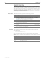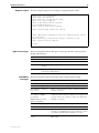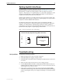
1
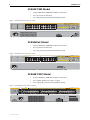
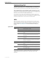
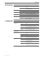
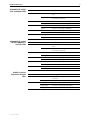
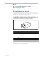
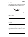
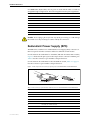
AT-8600 Series Switch
Hardware Reference
AT-8624T/2M
AT-8624PoE
AT-8648T/2SP
AT-8600 Series Hardware Reference
Document Number C613-03080-00 REV G
© 2006-2008 Allied Telesis Inc. All rights reserved. No part of this publication may be
reproduced without prior written permission from Allied Telesis Inc.
Allied Telesis Inc. reserves the right to change specifications and other information in
this document without prior written notice. The information provided herein is subject
to change without notice. In no event shall Allied Telesis Inc. be liable for any incidental,
special, indirect, or consequential damages whatsoever, including but not limited to lost
profits, arising out of or related to this manual or the information contained herein, even
if Allied Telesis Inc. has been advised of, known, or should have known, the possibility
of such damages.
All company names, logos, and product designs that are trademarks or registered
trademarks are the property of their respective owners.
Hardware Reference
3
Contents
Models Covered by this Document .................................................................... 4
Hardware Description ....................................................................................... 4
Switch Overview ......................................................................................... 4
AT-8624T/2M Model .................................................................................. 6
AT-8624PoE Model ..................................................................................... 6
AT-8648T/2SP Model .................................................................................. 6
Implementing PoE ............................................................................................. 7
LEDs ................................................................................................................. 7
Expansion Options .......................................................................................... 11
Switch Start-Up .............................................................................................. 12
Ports ............................................................................................................... 15
RS-232 Terminal Port (ASYN0) .................................................................. 15
RJ-45 Ports ............................................................................................... 16
Redundant Power Supply (RPS) ....................................................................... 17
Cables ............................................................................................................ 19
Terminal and Modem Cables .................................................................... 19
Cable Guidelines ...................................................................................... 21
Using AT-TFTP Server ....................................................................................... 21
Using Windows Terminal and Hyperterminal ................................................... 22
Test Facility ..................................................................................................... 25
10/100 Ethernet LAN Port Tests ................................................................ 26
Testing Switch Interfaces ................................................................................. 27
Troubleshooting .............................................................................................. 27
Common Problems and Solutions ............................................................. 28
For More Information ...................................................................................... 29
C613-03080-00 REV G
4
AT-8600 Series
Models Covered by this Document
This Hardware Reference includes information on the following models:
■
AT-8624T/2M 24-port 10BASE-T/100BASE-TX
■
AT-8624PoE
■
AT-8648T/2SP 48-port 10BASE-T/100BASE-TX
The latest Hardware Reference can be found at www.alliedtelesis.com/
support/software.
Hardware Description
This section provides an overview of the hardware features for AT-8600 Series
switches. Hardware descriptions for expansion modules are in the Expansion
Modules Installation Guide. These references can be found on the CD-ROM
provided with your switch, or can be downloaded from
www.alliedtelesis.com/support/software.
Switch Overview
RJ-45 copper ports ensure industry-standard compatibility, while two
expansion module bays add configuration flexibility.
Dimensions
■
Height = 44 mm (plus 5.5 mm if the rubber feet are used)
■
Width = 440 mm (excluding rack-mounting brackets)
■
Depth:
•
AT-8624T/2M = 223mm
•
AT-8624PoE = 408mm
•
AT-8648T/2SP = 254mm
■
Weight = not more than 7 kg (excluding power cord and expansion
modules)
Mounting system
■
1 RU 19-inch rack mounting
Environmental
conditions
■
Operating temperature range: 0 to 40º C (32 to 104º F)
■
Storage temperature range: -25 to 70º C (-13 to 158º F)
■
Operating humidity range: 5% to 80% non-condensing
■
Storage humidity range: 5 to 95% non-condensing
■
EMC: EN55022, AS/NZS CISPR22 class A, FCC CFR47 Part 15 Class A,
and VCCI Class A
■
Immunity testing to EN55024
■
Flicker and Harmonics testing to EN61000-3-2 and EN61000-3-3
■
Safety: UL60950-1, CAN/CSA-C22.2 No. 60950-1-03, EN60950-1,
EN60825-1
■
Ethernet port and System status LEDs
■
Mode button
■
For a complete list of LEDs and their functions, see “LEDs” on page 7.
Regulatory
standards
LEDs
C613-03080-00 REV G
Hardware Reference
Power Supply Unit
Switching core
Processing core
Asynchronous serial
port
Expansion module
bays
C613-03080-00 REV G
5
■
Universal 100/240 VAC 50/60 Hz input
■
Redundant DC Power connection
■
Advanced ASIC switch chip
■
Wire-speed L2 and L3 IP Switching
■
200 MHz CPU
■
16 MBytes RAM
■
8 MBytes flash memory
■
Up to 115 kbps
■
Standard DB9 female RS-232 connector
Expansion module bays are included on the AT-8624T/2M and AT-8624PoE
switches.
■
2 bays for expansion modules
■
Support for gigabit Ethernet expansion modules
6
AT-8600 Series
AT-8624T/2M Model
•
24-port 10BASE-T/100BASE-TX (RJ-45 connectors)
•
Two expansion module bays
•
Auto-negotiating advanced fast Ethernet switch
Figure 1: AT-8624T/2M front and rear panels
1
3
5
7
9
11
13
15
17
19
21
AT-8624T/2M Layer 3 Fast Ethernet Switch
23
1
5
7
9
11
13
15
17
19
21
23
LINK
26
25
3
2
4
6
8
10
12
14
16
18
20
22
STATUS
RS-232
TERMINAL PORT
COL
FAULT
MODE
100
MASTER
LINK
FULL
RPS
MODE
ACT
PWR
2
24
MODE
4
6
8
10
12
14
16
18
20
22
24
AT-8624PoE Model
•
24-port 10BASE-T/100BASE-TX (RJ-45 connectors)
•
Two expansion module bays
•
Auto-negotiating advanced fast Ethernet switch
Figure 2: AT-8624TPoE front and rear panels
1
3
5
7
9
11
13
15
17
19
21
23
100 LINK
ACT
10 LINK
FULL DUP
PD ON
1
3
5
7
AT-8624POE Layer 3 Fast Ethernet Switch
ACT
HALF DUP
COL
PD ERR
MAX CURRENT
9
11
13
15
17
19
21
23
MODE
STATUS
RS-232
TERMINAL PORT
FAULT
26
25
MASTER
RPS
PWR
2
4
6
8
10
12
14
16
18
20
22
24
2
4
6
8
10
12
14
16
18
20
22
24
AT-8648T/2SP Model
•
48-port 10BASE-T/100BASE-TX (RJ-45 connectors)
•
Two Gigabit uplink ports, SFP or copper
•
Auto-negotiating advanced fast Ethernet switch
Figure 3: AT-8648T/2SP front and rear panels
LINK
49
49R MODE
LINK
CLASS 1
LASER PRODUCT
DO NOT STARE
INTO BEAM
AT-8648T/2SP Layer 3 Fast Ethernet Switch
STATUS
SFP
LINK
50
LINK
C613-03080-00 REV G
50R MODE
COL
FLT
SPD
MSTR
FDX
RPS
ACT
PWR
MODE
Hardware Reference
7
Implementing PoE
The IEEE 802.3af standard, which is the IEEE standard for PoE, describes two
methods for implementing PoE over twisted pair cabling. One method uses the
same strands that carry the network traffic and the other the spare strands.
The PoE implementation on the AT-8624PoE switch transmits power over the
same strands that carry the network traffic (strands 1, 2, 3 and 6). The power
transfer does not interfere with the network traffic. The power and the network
traffic can coexist on the same strands simultaneously.
Powered devices that comply with the IEEE 802.3af standard support both
methods of power delivery. As long as a powered device is compliant with the
standard, it should be able to receive its power from the switch.
LEDs
The following tables outline how the switch and expansion modules report
faults and operational activities. Expansion modules are optional and can be
purchased separately. Contact an authorised Allied Telesis distributor or
reseller, or visit www.alliedtelesis.com for more information on expansion
modules.
System LEDs
LED
State
Description
FAULT
Off
Switch operation is normal.
Red
The switch or management software is malfunctioning.
1 flash
A switch fan has failed.
3 flashes
The main PSU has failed and the RPS is now providing
power.
4 flashes
The RPS Monitor is set to ON, and the RPS is not
functioning, either because it has failed or has been
switched off.
5 flashes
The RPS Monitor is set to ON, but the RPS is not
connected.
7 flashes
For the AT-8624T/2M and AT-8624PoE switches: An
expansion module has been inserted or removed while
the switch is powered on.
MASTER
Off
This LED is not supported.
RPS
Green
An optional redundant power supply is connected to the
switch.
OFF
There is no optional redundant power supply connected
to the switch.
Green
The switch is receiving power and the voltage is within
the acceptable range.
Off
The switch is not receiving power.
PWR
Use the Mode Select button to toggle the Mode LEDs to the desired state.
Toggling the Mode Selection button does not affect the normal switch
operations.
C613-03080-00 REV G
8
AT-8624T/2M switch
Link and Mode LEDs
AT-8600 Series
LED
State
Description
LINK
OFF
There is no link between the port and the endnode.
Green
A valid link has been established between the
port and the end-node.
OFF
No data collisions are occurring on the port.
Flashing Green
Data collisions are occurring on the port.
OFF
The port is operating at 10 Mbps.
Green
The port is operating at 100 Mbps.
OFF
The port is operating in half-duplex mode.
Green
The port is operating in full-duplex mode.
OFF
There is no activity on the port.
Flashing Green
There is activity on the port. It is transmitting
and/or receiving data.
Mode - COL
Mode - 100
Mode - FULL
Mode - ACT
AT-8624PoE switch
Link and Mode LEDs
LED
State
Description
L/A Status
(Top LED)
OFF
There is no link between the port and the endnode.
Green
The port is operating at 100 Mbps.
Flashing Green
There is activity on the port. It is transmitting
and/or receiving data at 100 Mbps.
Amber
The port is operating at 10 Mbps.
Flashing
Amber
There is activity on the port. It is transmitting
and/or receiving data at 10 Mbps.
Mode LEDs
(Bottom LED)
OFF
Either DC mode or PoE mode.
D/C Mode
OFF
There is no link between the port and the endnode.
Green
The port is operating in full duplex mode.
Amber
The port is operating in half-duplex mode.
Flashing
Amber
The port is operating in half-duplex mode and
data collisions are occurring on the port.
OFF
There is no powered device detected.
Green
The end node is a powered device and the port
is providing power to it.
Amber
The port is experiencing a problem providing
PoE to the end node.
Flashing
Amber
The port is connected to a powered device but
providing power to it would exceed the
maximum PoE power budget of the switch.
PoE Mode
C613-03080-00 REV G
Hardware Reference
AT-8648T/2SP switch
Link and Mode LEDs
9
LED
State
Description
LINK
OFF
There is no link between the port and the endnode.
Green
A valid link has been established between the
port and the end-node.
OFF
No data collisions are occurring on the port.
Flashing Green
Data collisions are occurring on the port.
OFF
The port is operating at 10 Mbps.
Green
The port is operating at 100 Mbps.
OFF
The port is operating in half-duplex mode.
Green
The port is operating in full-duplex mode.
Flashing Green
There is activity on the port
OFF
There is no activity on the port.
LED
State
Description
LINK
OFF
There is no link between the port and the endnode.
Green
A valid link has been established between the
port and the end-node.
OFF
No data collisions are occurring on the port.
Flashing Green
Data collisions are occurring on the port.
OFF
The port is operating at 10/100 Mbps.
Green
The port is operating at 1000 Mbps.
OFF
The port is operating in half-duplex mode.
Green
The port is operating in full-duplex mode.
Flashing Green
There is activity on the port
OFF
There is no activity on the port.
Mode - COL
Mode - SPD
Mode - FDX
Mode - ACT
AT-8648T/2SP switch
10/100/1000Base-T
and SFP LEDs
Mode - COL
Mode - SPD
Mode - FDX
Mode - ACT
AT-A45/xx Series
Expansion Module
LEDs
LED
State
Description
LINK
Steady green
The port has established a valid link with the
end node.
Flashing green
The port is transmitting and/or receiving data.
Steady green
The port is operating in full duplex.
Steady amber
The port is operating in half duplex.
Flashing amber
Collisions are occurring on the port.
Duplex
C613-03080-00 REV G
10
AT-8600 Series
AT-A46 Expansion
Module LEDs
AT-A47 Expansion
Module LEDs
AT-A65 Expansion
Module LEDs
LED
State
Description
LINK 10
Green
The port has established a valid 10 Mbps link
with the end node.
LINK 100
Green
The port has established a valid 100 Mbps link
with the end node.
Both LINK 10 and
LINK 100
Green
The port has established a valid 1000 Mbps link
with the end node.
FULL DUPLEX
Green
The port is operating in full duplex.
OFF
The port is operating in half duplex.
ACTIVITY
Green
The port is transmitting and/or receiving data.
LED
State
Description
LINK
Steady green
The port has established a valid 1000 Mbps link
with the end node.
ACTIVITY
Flashing green
The port is transmitting and/or receiving data.
LED
State
Function
10
Green
The port is operating at 10Mbps.
Off
The port is not operating at 10Mbps.
Green
The port is operating at 100Mbps.
Off
The port is not operating at 100Mbps.
Both 10 and 100
Green
The port is operating at 1000Mbps.
FDX
Green
The port is operating in full duplex mode.
Off
The port is operating in half duplex mode.
Flashing green
There is data activity on the port.
Off
There is no data activity on the port.
100
ACT
C613-03080-00 REV G
Hardware Reference
11
Expansion Options
Expansion modules increase switching capacity by providing two extra ports
and by allowing switches to be linked together in stacks. Use only the modules
in the following table.
Expansion Module
Port Type
Connector Type
AT-A45/MT
100Base-FX
MT-RJ
AT-A45/5C
100Base-FX
SC
AT-A45/5C-SM15
100Base-FX
SC
AT-A46
10/100/1000BASE-T
RJ-45
AT-A47
1000Base-T (GBIC)
GBICs are sold separately.
AT-A65
1000Base-X SFP
expansion bay, or
SFPs are sold separately.
10/100/1000Base-T
copper port
Copper port takes an
RJ-45 connection.
For a current list of expansion modules or more information, contact your
authorised Allied Telesis distributor or reseller. You can also see these
documents:
■
AT-A65 Expansion Module Installation and Safety Guide for the AT-A65
module only
■
AT-A45/xx Series, AT-A46, and AT-A47 Expansion Modules Installation Guide
for the other expansion modules available for AT-8600 Series switches.
You can download these documents and updates from
www.alliedtelesis.com/support/software.
You need Adobe® Acrobat® Reader® software to view, search, or print these
documents. You can download it from www.adobe.com.
Adding and Removing Expansion Modules
Hot-swapping expansion modules is possible on AT-8624PoE and
AT-8624T/2M switches. If a module is inserted or removed while the switch is
powered on, the Fault LED flashes 7 times. You must restart the switch to turn
off the flashing LED, and make a module ready for operation. Until the switch
is restarted, the output of the show system and show switch port commands
cannot reflect the newly inserted or removed expansion module.
C613-03080-00 REV G
12
AT-8600 Series
Switch Start-Up
When the switch starts up following a power cycle or an operator-initiated
reboot (using the reset button or restart command), it performs a series of tests
and sends messages to the terminal or PC connected to the ASYN0 port. After
the switch successfully starts, a prompt is displayed for you to log in. Refer to
the Installation and Safety Guide for basic login instructions or to the Getting
Started chapter in the Software Reference.
Process flow
Overrides
When the switch starts, it performs the following operations.
Stage This happens...
Done by...
1
Self-tests run that check basic operations.
Boot ROM
2
A prompt is displayed briefly to allow a user-override. Users
can change the startup process by pressing special keys (see
Overrides). If they enter nothing, the process continues.
Boot ROM
3
The flash boot release is loaded as the install software.
Boot ROM
4
Install information is checked and the switch boots up from
either the preferred or default install.
Boot ROM
5
The startup configuration script that the user specified is
executed.
Preferred or
default software
6
Startup is complete and the switch starts switching traffic if
devices connected to it are sending traffic.
Release software
The switch pauses briefly during routine startup messages to display the
following prompt:
Force EPROM download (Y)?
If you do nothing, switch software is loaded along with a preconfigured
startup script. For troubleshooting, change the process by using the following
keys.
Pressing this key... Forces the switch to...
C613-03080-00 REV G
Y
Load the flash boot release with no patch.
S
Start with the default configuration so that any boot script is ignored.
Ctrl+D
Enter diagnostics mode.
Hardware Reference
Regular output
13
The following messages are an example of output from the switch.
INFO:
INFO:
PASS:
INFO:
INFO:
Force
INFO:
Self tests beginning.
RAM test beginning.
RAM test, 32768k bytes found.
Self tests complete.
Downloading switch software.
EPROM download (Y) ?
Initial download successful.
INFO: Initialising Flash File System.
INFO: IGMP packet trapping is active for IGMP snooping, L3FILT
is activated
INFO: Executing configuration script <flash:boot.cfg>
INFO: Switch startup complete
login:
Types of messages
AlliedWare
messages
The following table explains the types of messages that the switch generates
during initial startup.
Type
Description
INFO
An action has been taken by the system.
PASS
A test has been completed successfully.
ERROR
An error message that a test has failed but the system continues to
operate.
FAIL
An error message that a fatal error condition has caused the system to halt
in an unrecoverable fashion.
The following table explains messages in the output from the switch.
Message
Description
INFO: Self tests beginning.
Code loader tests are about to begin.
INFO: RAM tests beginning
RAM tests are about to begin.
PASS: RAM test, 131072k
bytes found
RAM test passed and the switch is using the indicated
amount of memory.
ERROR: RAM test test-number.
Error address = address
The given RAM test failed at the given address, which
means the memory system is faulty. The test repeats until
it passes. If the error continues, contact your authorised
distributor or reseller.
For example:
ERROR: RAM test 5. Error
address = 00345678
C613-03080-00 REV G
INFO: BBR tests beginning
BBR battery tests are about to begin.
PASS: BBR test. Battery OK
BBR battery tests passed.
ERROR: BBR Battery low
BBR battery test failed, indicating that the battery is
running low. The BBR battery must be replaced. Contact
your authorised Allied Telesis distributor or reseller.
PASS: BBR test, 512k bytes
found
BBR size/location test passed with the indicated amount of
BBR found.
14
AT-8600 Series
Message
Description (Continued)
FAIL: BBR test. Error address =
location
BBR size/location test failed at the given location. The test
at this location failed, indicating the end of memory, but a
valid location was discovered in the 255 long words
following this location. The BBR system must be replaced.
Contact your authorised distributor or reseller.
FAIL: BBR test, only 16k bytes
found
The BBR size/location test completed, but only the
displayed amount of memory was found. This amount is
less than the minimum required to run the switch
software.
INFO: Self tests complete
Startup tests have finished.
INFO: Downloading switch
software
The process of downloading the switch software and
vector table from ROM is about to begin.
ERROR: Code load retried
Loading code from ROM to RAM failed. The load is retried
a number of times, and the error message is displayed
each time it fails. The fail message is displayed if the switch
reaches the maximum number of attempts.
FAIL: Code load failed
Force EPROM download (Y) ?
Prompt that lets you override the standard startup
sequence, typically when troubleshooting.
INFO: Initial download
succeeded
Startup tests and download are complete, and the switch
software is about to be started.The release is now
decompressed. This may take a few seconds.
INFO: Downloading
compressed release. This may
take up to 1 minute...
The main switch software is decompressed before being
loaded into RAM.
INFO: Loading software into
memory. This may take up to 1
minute...
INFO: Executing configuration
script <script-name>
Configuration commands in the given script file begin
executing if selected by the user. If the script has an error,
appropriate error messages are displayed.
INFO: Switch startup complete The startup process is complete and the switch is ready. If
devices connected to it are sending traffic, then the switch
begins switching operations.
C613-03080-00 REV G
Hardware Reference
15
Ports
This section explains pin assignments for the following:
■
RS-232 Terminal Port (ASYN0)
■
RJ-45 Ports
RS-232 Terminal Port (ASYN0)
The RS-232 ASYN0 port connects the switch to a management device for initial
configuration. This port allows the software on the switch to be accessed from a
terminal or a PC running terminal emulation software.
The ASYN0 port has an RJ-45 socket with an industry recognised pinout. This
requires using a straight-through RJ-45 cable with an RJ-45 DB9 connector
when the switch is connected to a terminal or PC. The socket is wired as a DTE
and the pin layout is shown in the following figure and table.
8
1
rjpin1
Pin
Role
1
RTS
2
DTR (DSR and DTR are connected but have no other internal connection)
3
TXD
4
GND
5
GND
6
RXD
7
DSR (DTR and DSR are connected but have no other internal connection)
8
CTS
See “Terminal and Modem Cables” on page 19 for more information on
connection options for the RS-232 terminal port.
C613-03080-00 REV G
16
AT-8600 Series
RJ-45 Ports
For 10BASE-T/100BASE-TX connections, a twisted pair cable must be used.
Each pair is identified by two different colours. For example, one wire might be
red, and the other red with a white stripe. An RJ-45 connector must be fitted to
both ends of the cable. The following figure shows the pin layout for RJ-45
connectors.
Figure 4: RJ-45 pin layout
8
1
8
1
RJPIN
With 10BASE-T/100BASE-TX cables, pins 1 and 2 are used for transmitting
data, while pins 3 and 6 are used for receiving data. The following table lists
the RJ-45 Pin assignments.
Pin Number
Assignment1
1
TX+
2
TX-
3
RX+
6
RX-
1. The “+” and “-” signs represent the polarity of the wires that make up each wire pair.
If a twisted pair cable is to join two ports and only one of the ports has an
internal crossover, the two pairs must be straight through, as listed in the
following table.
End 1
End 2
1 (TX+)
1 (TX+)
2 (TX-)
2 (TX-)
3 (RX+)
3 (RX+)
6 (RX-)
6 (RX-)
If a twisted pair cable is used to join two ports and either both ports are
labelled with an “X” or neither port is labelled with an “X”, a crossover must be
included in the wiring. The following table lists the RJ-45 crossover wiring pin
assignments.
C613-03080-00 REV G
End 1
End 2
1 (TX+)
3 (TX+)
2 (TX-)
6 (TX-)
3 (RX+)
1 (RX+)
6 (RX-)
2 (RX-)
Hardware Reference
17
For 1000BASE-T RJ-45 cables, all four pairs are used and the cable is wired in a
straight-through configuration. The following table lists the pin assignments.
End 1
End 2
1 Pair 1+
1 Pair 1+
2 Pair 1-
2 Pair 1-
3 Pair 2+
3 Pair 2+
6 Pair 2-
6 Pair 2-
4 Pair 3+
4 Pair 3+
5 Pair 3-
5 Pair 3-
7 Pair 4+
7 Pair 4+
8 Pair 4-
8 Pair 4-
Caution Do not plug a phone jack into any RJ-45 port. Doing so could damage
the switch. Use only twisted pair cables with RJ-45 connectors.
Redundant Power Supply (RPS)
AT-8600 Series switches have a Redundant Power Supply (RPS) connector on
their rear panel. The RPS connector differs for different switch models.
For information about the RPS for AT-8624T/2M and AT-8648T/2SP switches,
Figure 5 illustrates the pin layout to the 16-pin molex connector and RPS port.
Table 1 lists the connector’s pin numbers and pin functions.
For information about the RPS for the AT-8624PoE switch, Table 2 on page 18
lists the connector’s pin numbers and pin functions.
Figure 5: RPS 16-pin molex connector pin layout for AT-8624T/2M and AT-8648T/2SP
9
1
16
9
1
16
8
8
Table 1: RPS connector pin numbers and functions for AT-8624T/2M and AT-8648T/2SP
C613-03080-00 REV G
Pin Number
Function
1
+12 VDC
2
Remote Sense (RS) +5 VDC
3
Remote Sense (RS) Ground
4
Remote Sense (RS) +3.3 VDC
5
Redundant Power Supply (RPS) Present
6
Ground (+3.3 VDC Return)
7
Ground (+5 VDC Return)
8
+5 VDC
9
Ground (+12 VDC Return)
10
+3.3 VDC
18
AT-8600 Series
Table 1: RPS connector pin numbers and functions for AT-8624T/2M and AT-8648T/2SP
AT-8624PoE pin layout
Pin Number
Function
11
Ground (+3.3 VDC Return)
12
+3.3 VDC
13
Ground (+3.3 VDC Return)
14
+3.3 VDC
15
+5 VDC
16
Ground (+5 VDC Return)
For the AT-8624 PoE switch, the pin layout is different. The molex connector
has 15 power pins, plus 2 high current pins. The pin layout is as follows.
For the female unit connector:
■
The top row contains 7 pins. Pins are numbered 1-7, from right to left.
■
The bottom row contains 8 pins. Pins are numbered 8-15, from right to left.
■
On the left of the connector is the A2 pin.
■
On the right of the connector is the A1 pin.
For the male cable connector:
■
The top row contains 7 pins. Pins are numbered 1-7, from left to right.
■
The bottom row contains 8 pins. Pins are numbered 8-15, from left to right.
■
On the right of the connector is the A2 pin.
■
On the left of the connector is the A1 pin.
Table 2: RPS Connector Pin Numbers and Functions for AT-8624PoE.
C613-03080-00 REV G
Pin Number
Function
1
48V
2
48V Remote Sense
3
Redundant Power Supply (RPS) Present
4
12V Remote Sense Return
5
12V Remote Sense
6
+12V
7
+3v3
8
48V
9
48V
10
48V Remote Sense Return
11
Redundant Power Supply (RPS) OK
12
+3v3 Remote Sense Return
13
+3v3 Remote Sense
14
+3v3
15
+3v3
A1
Isolated Ground
A2
Ground
Hardware Reference
19
Cables
This section describes how to make cables for connecting switch interfaces to
networks, terminals, and printers.
Terminal and Modem Cables
The following figure shows how to wire cables to connect a standard VT100
compatible terminal, or a modem, to the switch’s RS-232 Terminal Port.
DB9 Male
(to switch/DCE)
Not connected
→ (TXD)
← (RXD)
← (CD)
(GND)
→ (DTR)
← (CTS)
→ (RTS)
← (RING)
Pin 1
DB9 Female
(to PC/terminal/DTE)
1
2
3
4
5
6
7
8
9
1
2
3
4
5
6
7
8
9
Pin 5
Pin 5
(DCD)
(RXD)
(TXD)
(DTR)
(GND)
(DSR)
(RTS)
(CTS)
(RING)
Pin 1
Cable
Pin 6
Pin 9
DB9 Male Pin View
Notes:
(1)
(2)
Pin 9
Pin 6
DB9 Female Pin View
→ Output from switch; ← Input to switch.
Cable version 1.0.
DB9MDB9Fsw
C613-03080-00 REV G
20
AT-8600 Series
The following figure shows the pin wiring diagram for a DCE RS-232 Terminal
Port (DB9 female connector) male to male modem cable
DB9 Male
(to switch/DCE)
Not connected
→ (TXD)
← (RXD)
← (CD)
(GND)
→ (DTR)
← (CTS)
→ (RTS)
(RING)
Pin 1
DB9 Male
(to modem/DCE)
1
2
3
4
5
6
7
8
9
3 (TXD)
2 (RXD)
1 (DCD)
5 (GND)
4 (DTR)
8 (CTS)
7 (RTS)
9
6 Not connected
Pin 5
Pin 5
Pin 1
Cable
Pin 6
Pin 9
Pin 9
DB9 Male Pin View
Notes:
(1)
(2)
Pin 6
DB9 Male Pin View
→ Output from switch; ← Input to switch
Cable version 1.0.
DB9MDB9Fsw
The switch’s RS-232 terminal port has a DCE female socket so that you can use
a straight-through cable when connecting the switch to a terminal or PC.
However, output from the show asyn command still has a DTE perspective.
The internal DTE pin roles are listed in the following table.
C613-03080-00 REV G
Pin
Role
2
TXD
3
RXD
4
CD
5
GND
6
DTR
7
CTS
8
RTS
Hardware Reference
21
Cable Guidelines
The following table lists port, connector, and cable combinations for each
model.
Model
Port Type(s)
Connector
Type(s)
Cable Type1
Maximum
Cable Length
AT-8624T/2M,
AT-8624PoE
10BASE-T/100BASE-TX
RJ-45
10BASE-T Category 3 or better
100m (328ft)
AT-8648T/2SP
10BASE-T/100BASE-TX
100BASE-TX Category 5 or better
RJ-45
10BASE-T Category 3 or better
100m (328ft)
100BASE-TX Category 5 or better
10/100/1000BASE-T
RJ-45
1000BASE-T Category 5e, or better
100m (328ft)
SFP
RJ-45
1000BASE-T Category 5e, or better
Fibre
Fibre Cable
100m (328ft)
Dependent on
SFP type
1. Refer to the IEEE 802.3 standards for further cable information
Using AT-TFTP Server
This section explains how to access and use the AT-TFTP Server. You can
transfer configuration files as well as download software upgrades with
AT-TFTP Server.
1.
If AT-TFTP Server has not been installed, install it from the Documentation
and Tools CD-ROM.
Select AT-TFTP Server from the Start > Programs > Allied Telesis >
AT-TFTP Server menu.
2.
To set preferences for the AT-TFTP Server, select Options from the File
menu to display the Set Preferences dialog box shown below.
The "Default file transfer directory" field specifies the directory that
AT-TFTP Server reads from or writes to for file requests that do not include
a directory specification.
C613-03080-00 REV G
22
AT-8600 Series
Enter a path name in the "Restrict to directory" field to prevent
unauthorised access to private directories. AT-TFTP Server uses the
specified directory even when file requests contain references to other
directories.
To prevent files from being written to the PC, click the Read only checkbox.
To use the PC to archive scripts created using the switch's create config
command, click the Read Write checkbox.
Click the OK button when you finish.
3.
To load a file from AT-TFTP Server to the switch, type the following
command on a terminal connected to the RS-232 Terminal Port (ASYN0):
load method=tftp file=filename server=ipadd dest=flash
where filename is the name of the file to download and ipadd is the IP
address of the PC running AT-TFTP Server.
4.
To save a TFTP Server log, select Save As from the File menu. TFTP
requests are logged to the AT-TFTP Server main window.
Using Windows Terminal and
Hyperterminal
You can use a PC running terminal emulation software as the manager console,
instead of a terminal. There are many terminal emulation applications
available for PCs, but the most readily available are the Terminal and
HyperTerminal applications included in Microsoft Windows 98, 2000, and
XP Professional. In standard Windows installations, HyperTerminal is
available from the Communications submenu.
The key to successful use of terminal emulation software with the switch is to
configure the software and switch with matching communications parameters.
The following procedure can be applied to most terminal emulation programs.
Dialog boxes in the procedure are from Windows 2000 and XP Professional.
To configure Windows HyperTerminal for 2000 and XP Professional
1.
C613-03080-00 REV G
Start the program in Windows by doing one of the following:
•
Select Programs > Accessories > Communications > HyperTerminal.
•
Double-click the Hypertrm.exe icon.
Hardware Reference
23
2.
3.
C613-03080-00 REV G
In the Connection Description dialog box:
•
Enter a name for the connection, such as Admin.
•
Select an icon from the scrollable list and click the OK button.
In the “Connect using” field on the Connect To dialog box, select the COM
port on the PC used to connect to the switch. and click the OK button.
24
C613-03080-00 REV G
AT-8600 Series
4.
In the COMn Properties dialog box, set port parameters as follows, and click
the OK button.
5.
From the main HyperTerminal window, select Properties from the File
menu. Click the Settings tab, and set the Properties dialog box as follows.
Hardware Reference
25
6.
Click ASCII Setup to display the ASCII Setup dialog box, and ensure the
following options are not selected:
•
Echo typed characters locally
•
Append line feeds to incoming line ends
Set other parameters as necessary and click the OK buttons on both dialog
boxes to close them.
7.
Save the current session by selecting Save from the File menu on the main
HyperTerminal window. This creates a connection icon with the name you
assigned in the HyperTerminal group.
To use the configuration, double-click the connection icon. When the
HyperTerminal window appears, press the Enter key several times; the
switch’s login prompt is then displayed.
Test Facility
The Test Facility is designed to test the switch’s physical interfaces. Testing
should not be performed while the switch is operational as the presence of a
loopback plug may cause feedback of network traffic. Also, any interfaces
being tested are dedicated to the Test Facility. The Test Facility can be thought
of as a specialised interface module like PPP or Frame Relay.
The Test Facility is built into all AT-8600 Series software. For detailed
information on operating the Test Facility, see the Test Facility chapter of the
AT-8600 Series Software Reference.
C613-03080-00 REV G
26
AT-8600 Series
10/100 Ethernet LAN Port Tests
A loopback plug is required to run the first part of the Ethernet LAN test. See
“Testing Switch Interfaces” on page 27 for details of how to make a loopback
plug. To start an Ethernet interface test, use the command:
enable test int=portn
where n is the Ethernet interface number. The test runs about 4 minutes. You
can use the following command to display the test progress and results:
Display test results with the command:
show test
The following figure shows example output from the this command.
Figure 6: Example output from the show test command
Board
ID Bay Board Name
Rev
Serial number
---------------------------------------------------------------------------Base
238
8624 AT-8624T/2M
M1-1 12345678912345
Uplink
88
1 AT-A46
P1-0 98765432198765
Duration
Details
Interface State
Result
Type (minutes) Data( %OK ) Control
---------------------------------------------------------------------------port1
no test
port2
no test
port3
no test
port4
no test
port5
no test
port6
no test
port7
no test
port8
no test
port9
no test
port10 no test
port11 no test
port12 no test
port13 no test
port14 no test
port15 no test
port16 no test
port17 no test
port18 no test
port19 no test
port20 no test
port21 no test
port22 no test
port23 no test
port24 no test
port26 no test
asyn0
no test
-
C613-03080-00 REV G
Hardware Reference
27
Testing Switch Interfaces
Loopback plugs are used in conjunction with Test Facility software to test the
physical interfaces on the switch (see the section “Test Facility” on page 25 of
this Reference, and the Test Facility chapter of the AT-8600 Series Software
Reference). The purpose of a loopback plug is to connect the output pins on the
interface to the input pins so that any data transmitted over the interface is
looped back and received at the same interface.
Gigabit copper interfaces (as found on the AT-A39/T expansion module, and
the AT-8648T/2SP) cannot be looped back. Loopback plugs can only be used in
conjunction with 10/100 Ethernet interfaces.
On interfaces with control signals, these are also looped back. The data
received on the interface is compared with the data transmitted to determine
whether or not the interface is functioning correctly. In order to produce a
comprehensive test report for the interface being tested, most tests performed
by the Test Facility require a loopback plug to be inserted.
Figure 7: Ethernet twisted pair (TP) loopback plug
Twisted Pair (TP) Loopback Plug (RJ45 connector)
8 7 6 5 4 3 2 1
TX+
TXRX+
RX-
1
2
3
4
5
6
7
8
Not
connected
Not
connected
•Not
Switch end view
of plug
RTPLOOPsw
Troubleshooting
Basic problems
C613-03080-00 REV G
To eliminate some basic problems:
1.
Make sure the power cord is securely connected.
2.
Check that the power supply voltage is stable.
3.
Check that the correct data cables are being used and that their connections
are secure.
4.
Make sure that other network devices are working properly.
5.
Use the show install command to check that the latest software release is
loaded. See the AT-8600 Series Software Reference for more information about
obtaining the latest software release.
6.
If the switch is malfunctioning, reboot it by entering the restart reboot
command. Alternatively, power OFF and ON the switch by disconnecting
and reconnecting the main power supply (including, if connected, the RPS
power).
28
AT-8600 Series
Common Problems and Solutions
Power LED is off
If the power LED is off, it may indicate the following:
■
a loose power cord
■
a power supply failure
Perform the following steps in sequence:
L/A LED on a port
is off
1.
Check that the power cord connections are secure.
2.
Check that all switches and circuit protection devices are in the ON position.
3.
Ensure that the supply voltage is within the operational range (110/240
VAC 50/60 Hz).
If the Link/Activity LED is off, it may indicate the following:
■
a loose data cable
■
the device at the other end of the connection is not working properly or is
turned off
■
the data cable is not wired correctly
■
the network administrator has manually disabled the port through the
software
■
the port’s selected transmission mode does not match that of the attached
device
Perform the following steps in sequence:
1.
Make sure the data cable connections are secure.
2.
Make sure the device at the other end of the connection is switched on and
working properly.
3.
Check that the data cable is wired correctly.
4.
If you can, log in and check the port status. Refer to the Installation and
Safety Guide for basic login instructions or to the Getting Started chapter in
the Software Reference.
5.
If the port is enabled, make sure the transmission speed matches that of the
connected device (auto-negotiating, full or half-duplex).
If the port is disabled, someone has used the software to manually disable
it. You should find out why the port was disabled before enabling it.
Fault LED is on
If the fault LED is on, it may indicate the following:
■
there is a problem with the switch or RPS PSU
■
the switch or management software is malfunctioning
■
a hardware fault is preventing switch start-up
Perform the following steps in sequence:
C613-03080-00 REV G
1.
Check “System LEDs” on page 7 for descriptions and explanations of LED
flashing sequences.
2.
Restart the switch by entering the RESTART REBOOT command.
3.
If you were attempting to download software or manage the switch via the
RS-232 terminal Port, check that connections between the Terminal Port and
local terminal or PC are secure.
Hardware Reference
29
If you cannot access the switch’s software because of a faulty RS-232
Terminal Port connection, you can still manage the switch via Telnet or
SNMP until the problem is fixed.
Additional resources
4.
Unplug the switch and then plug it in again. If an RPS unit is present, you
will also have to disconnect and reconnect the RPS unit.
5.
Download the latest software release. See the AT-8600 Series Software
Reference for more information on how to obtain the latest software release.
■
www.alliedtelesis.com/support/software
■
the AT-8600 Series Software Reference
■
How To notes from the Resource Center on your Documentation and Tools
CD-ROM, or from www.alliedtelesis.co.uk/en-gb/solutions/techdocs.asp
For More Information
Document sets
The complete document set for the AT-8600 Series switches includes:
■
The AT-8600 Series Installation and Safety Guide, which provides safety and
statutory information, and outlines the procedure for installing switch
units.
■
This AT-8600 Series Switch Hardware Reference.
■
The AT-8600 Series Software Reference, which provides detailed information
on configuring the switch and its software.
■
The AT-A65 Expansion Modules Installation and Safety Guide, which outlines
the procedure for installing the AT-A65 expansion module and provides
technical specifications for the module.
■
The AT-A45/xx Series, AT-A46, and AT-A47 Expansion Modules Installation
Guide, which outlines the procedure for installing these expansion
modules, and provides technical specifications for the modules.
■
AT-TFTP Server for Windows, for downloading software releases.
■
Adobe Acrobat Reader, for viewing online documentation.
These documents can also be downloaded from
www.alliedtelesis.com/support/software.
You need Adobe® Acrobat® Reader® software to view, search, or print these
documents. You can download it from www.adobe.com.
Viewing
documentation on
the CD
If your switch shipped with a Documentation and Tools CD-ROM, use the
following steps to view the documentation:
1.
Insert the Documentation and Tools CD in the CD-ROM drive.
If the browser menu does not appear, select Run from the Start menu. Then
type d:\start.exe (where d: is the CD-ROM drive) in the text box, and click
the OK button.
C613-03080-00 REV G
2.
Install Adobe Acrobat Reader from the CD if necessary. It must be installed
in order to view the documentation.
3.
To view a specific document, click the document title.
30
AT-8600 Series
4.
To browse PDF documents, use any of the following to page through a
document:
•
toolbar buttons, such as the Next Page button
•
keyboard shortcuts, such as arrow keys
•
commands from the Document menu
•
mouse wheel
To go to a specific section or topic, click a bookmark, thumbnail, or
hypertext link.
Use the Search command to search for keywords or phrases.
For more information about using the Adobe Acrobat Reader, select Adobe
Reader Help from the Help menu.
5.
Contacting us
C613-03080-00 REV G
To install one of the tools from the CD, click the link on the browser menu.
With locations covering all of the established markets in North America, Latin
America, Europe, Asia, and the Pacific, Allied Telesis provides localized sales
and technical support worldwide. To find our representative nearest you, visit
Allied Telesis on the web at: www.alliedtelesis.com.