1
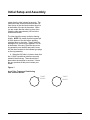
Bel Canto Design
SET 40
Single Ended 845 Triode Stereo Power Amplifier
User's Guide and
Operating Information
Bel Canto Design • © August 2000
SET 40
Single Ended 845 Triode Stereo Power Amplifier
The Bel Canto Design SET 40 uses the most simple and elegant of circuit architectures with the highest
quality of parts and construction to produce an audio amplifier which is unparalleled in recreating the
musical event.
Contents
Bel Canto Design Statement
3
Unpacking
4
Initial Setup & Assembly
5
Connecting the SET 40 into Your System
7
Technical Description
9
Specifications
10
Warranty Information
11
Page 2
SET 40 Owner's Manual
Bel Canto grew from the quest to achieve the ultimate musical
satisfaction from an audio system. This goal began with the discovery of the
inherent sonic qualities and musical performance potential of a nearly forgotten
technology, the single-ended triode amplifier. The ability of this type of amplifier
to recreate the musical experience and evoke a powerful emotional response in
the listener, much like the live event, inspired the development of the SET line of
amplifiers through the ultimate expression of this technology. The SET 40 circuit
was developed to be used as both a cornerstone for a modern audio system and
as a reference tool to explore the reasons behind the single-ended triode
amplifier's uniquely musical attributes.
For the better part of a decade this quest continued and has
resulted in a line of fine audio amplifiers that are designed to incorporate the
unparalleled musical reproduction of the single-ended triode architecture. Bel
Canto Design's goal for the SET Line is simply to provide the most expressive and
powerful musical experience outside of the live event. Bring some of the greatest
musicians and their performances into the intimacy of your home, for many years
to come.
The SET 40 represents the attainment of a goal and is designed to
provide very high value and to retain this value for many years, both because of
the quality of design and manufacturing and also the timelessness of each
component's musical performance.
Bel Canto Design
SET 40 Owner's Manual
Page 3
Unpacking
Carefully unpack each piece and check for
shipping damage. If there is any damage,
please contact your dealer or Bel Canto Design,
Ltd. Save all packing materials as the packing is
specially designed to protect the amplifier during
shipping or transporting. If you lose or damage
the packing materials or carton, please contact
your dealer or distributor before attempting to
transport the amplifiers.
Unpacking
The box containing your SET 40 contains the
following parts:
1 - SET 40 User's Guide
1 - Power Cable for connection to utility
power [6' 7" - 2 meters long]
1 - SET 40 audio power amplifier
The SET 40 power supply is preset for the
proper national voltages before you
receive it. The power cable will have the
correct plug for your local power system.
If you believe this is not true, please
contact your dealer immediately. Do not
attempt to alter or change power settings
yourself!
2 - 845 power triodes in a protective box,
these tubes may be shipped in a separate
shipping container.
1 - Bel Canto Owner's Warranty &
Registration Card
!
!
Warning
Do not connect power to this amplifier yet!
This power amplifier, like any electrical component, can be dangerous and cause injury unless
correct handling procedures are observed and used. Before powering this power amplifier it is
necessary to read and follow proper procedures concerning its setup and use.
Do not open up your SET 40 (do not remove the chassis covers). There are no user serviceable
parts inside. Any tampering of internal parts will immediately void your warranty.
Complete and mail the Owner's Registration Card immediately in order to activate your warranty.
Page 4
SET 40 Owner's Manual
Initial Setup and Assembly
!
Warning
1. Never remove the bottom panel of the amplifier. There are no fuses or user serviceable
components in the amplifier, and dangerous voltages could be present if the bottom cover is
removed. Removal of this cover or any tampering with the amplifier will immediately void the
warranty.
2. Never plug the amplifier into the power source without all tubes in place and the protective tube
covers attached to the top plate of the chassis.
3. Always use a correctly grounded power outlet to ground the chassis of the amplifier. If there
is any question about this refer to your dealer/importer or a qualified electrician.
4. Never connect the amplifier to any other audio components until directed to proceed later in this
manual.
Assembling the SET 40 requires that the 845
power triodes be placed in the tube sockets
prior to plugging the amplifier into the power
outlet.
NOTE: This procedure is not difficult or
dangerous if done according to the following
instructions, but it does require some care in
handling the 845 tube. If you are unsure of
yourself or would like more help than can be
given in this manual, please contact your dealer,
who will be pleased to help you set the SET 40
up. All of our dealers are chosen with this
service in mind, and we urge you to request
dealer assistance in setting up your system.
2. Remove the 845 tube from its wrapping. It
is important for tube life that oils from your
hands do not get on the upper part of the glass
tube envelope. Insert the 845 into the large
socket, taking care to line up the bayonet pin
protruding from the metal base of the tube with
the slot in the tube socket.
3. Push down on the tube until you feel that
the pin has reached the bottom of the slot in the
socket. Some force and slight movement of the
tube may be required to get the tube to clear the
contacts and go down far enough so that the
tube can rotate. Do not apply too much
rotational force until you are
Follow these steps in inserting or changing the
845 tube. (Total time for this procedure:
approximately 15 minutes.)
1. Be certain the SET 40 is not
connected to a power source. This is the
most important step! The amplifier could be
damaged if power is applied without the tubes in
place and extremely dangerous voltages are
present and assessable at the tube sockets if
power is on!
SET 40 Owner's Manual
Page 5
Initial Setup and Assembly
certain that the tube is down far enough. The
metal tube base should protrude less than 1/4"
from the top of the tube socket when the pin is
at the bottom of the slot in the socket. When
you are certain that the tube is in place, then
rotate the tube approximately 1/8 turn in the
clockwise direction.
The tube should be nearly vertical or leaning
slightly. NOTE: Be certain that the bayonet pin
is at the bottom of the slot before applying
rotational force on the tube. The pin could be
damaged if too much force is applied if it is not
at the bottom of the slot. Place the tube cover
ring assembly over the 845 and push it home
into the three sockets for the banana type plugs
on the ring assembly.
4. When the 845 tube is in place, check that
the 4-12AX7 input/driver tubes are correctly
seated in their sockets. These should be in
place when the amplifier is received. If there
are any questions at this point contact your
dealer.
Figure 1.
Input Tube Types and Positioning
One Channel Shown
12AX7
ECC83
Page 6
12AX7
ECC83
SET 40 Owner's Manual
Connecting and Use
Connecting the SET40 into
Your System
Input Connections
There is one pair of RCA input jacks for the
analog inputs. The right channel is marked with
a Red band and the left with a Black band.
The 845 output tubes are designed for
commercial use in and will provide at least 8000
hours of life as used in the SET circuit. This
translates to over 5 years of typical use. The
input tubes generally have 2000 hour life and
will need replacement every 1 1/2 to 2 years.
These tubes are available off the shelf from
current production at reasonable prices. Contact
your dealer or Bel Canto Design for
replacement.
Loudspeaker Connection
The loudspeaker connections use one of the
two pairs of output jacks behind the output
transformer on the top plate of the chassis. The
output jacks accept many types of wire
termination, although we recommend either a
high quality spade lug or the use of simple tinned
wire terminations for this hookup.
Determine the nominal impedance of your
loudspeaker. The 8 ohm switch position should
be used with loudspeakers which have greater
than 6 ohm minimum impedance. The 4 ohm
position should be used with loudspeakers with
3 to 6 ohm minimum impedance. The impedance
selector is between the loudspeaker outputs.
Power Switch
The rear panel power switch marked 0 1 will
take the amp out of standby when switched to
the 1 position. The input tube filaments are
always powered to insure a gentle turn on and
instant sound output.
Tube Life and Replacement
SET 40 Owner's Manual
Page 7
Amplifier Power and Loudspeaker
Selection
The SET 40 has a nominal power rating of 37
watts for each channel. While this may seem
like a low power output compared to many
amplifiers on the market, because of the class A
operation, the low distortion, wide power
bandwidth, and the grace that these amplifiers
have when overdriven, they will produce as
much or more level sound than many 100 watt
amplifiers. We suggest that you consider any
loudspeakers with average rated sensitivity of
86-87 dB/Watt/Meter or greater. Greater
sensitivity will allow higher listening levels
before either the amplifier or the loudspeaker
runs out of steam. Remember that with many
speakers in even a relatively large room the
amplifiers will be operating at average levels of
only 1-5 watts each with typical music at quite a
high average sound level of 90 dB. This leaves
15 to 17 dB of amplifier headroom for musical
peaks.
We have successfully used the SET 40 with
many types of loudspeakers, including dynamic
cone, planar magnetic and electrostatic types.
When choosing a loudspeaker many variables
come into play, therefore we will not attempt to
recommend a type or set of 'brands' which you
should consider. Our suggestion is that you
work with the dealer representing the SET 40
and choose a loudspeaker which works well
for your tastes, in your room with your system.
A dealer which sells the SET 40 will be more
than competent to guide you in your selection.
When installing the amplifiers it is important that
they receive adequate ventilation. Allow at
least 6 inches above the amplifiers, and be
certain that the holes on the bottom cover are
open to air circulation (do not place them directly
on a thick carpet, as this will block the bottom
ventilation holes). Do not use the SET 40 in a
closed cabinet unless fan cooling is allowed or
the amplifiers will overheat and could be
damaged. They generate consider-able heat in
operation because of their single-ended class A
operation. With adequate ventilation on an open
shelf or stand they will cool themselves through
convection and will not require any additional
cooling.
When the setup is complete and all connections
are made, the power cord can be installed and
the power switch turned to the 'on' position.
The amplifiers will be operational nearly
immediately, and they require only 15 to 20
minutes to reach optimum performance. There
will be a short break-in period of 20 to 30 hours
when the amplifiers are first used. The sound
quality potential will improve during this period
as all of the components and tubes 'settle in'
during this time. Further improvement in sonic
performance will occur during the first 100 to
200 hours of use as the copper wire anneals
and all of the components settle in.
Amplifier Placement and Poweron
Page 8
SET 40 Owner's Manual
Technical Description
Circuit Description and Technical
Information
The philosophy behind the design of the SET 40
is based on the observation that simplicity of the
circuit and the reduction of the number of active
devices in an audio amplifier will permit the
greatest quantity of information to get through the
amplifier. This allows the illusion of music to be
most powerful and results in the amplifier
'disappearing' effectively from the playback chain.
This chameleon-like performance is achieved
through an elegantly simple circuit.
The primary design goal of the SET 40 was to
take the idea of the single ended (SE) triode
amplifier to its ultimate level, using only two triode
stages to keep distortion low and reduce the
number of active devices to a strict minimum, while
delivering enough power so that a wide range of
loudspeaker choices could be made for use in a
home audio system. Unlike other high power SE
triode amplifiers which use several stages of gain
and buffering, the SET 40 takes advantage of the
distortion cancellation and reduction which occurs
when using just two triode stages. The low
distortion figures at typical playback levels of 1-5
watts are achieved with no local or loop feedback.
This total absence of feedback also maximizes
the amplifier's ability to transmit the information
content in the music signal.
modulators) to drive a custom output transformer
which provides superb power handling and
bandwidth. The 845 tube is run at maximum
power in radio stations for over 8000 hours, you
should get similar performance life in the SET 40.
The SET 40 bandwidth is similar to many amplifiers
which use feedback and push-pull operation to
achieve good performance. The SET 40 achieves
this without resorting to these information robbing
circuit techniques.
The use of self bias for the 845 tube allows a
higher grid resistance to be used, permitting a
single high gain, relatively low power, input/driver
stage. This type of bias scheme is more difficult to
implement than grid bias schemes, requiring high
quality, high value decoupling capacitors, large
power resistors and a higher voltage on the main
supply. (This voltage is near 1200 V DC on the
SET 40!)
The input/driver stage uses two 12AX7s in a
modified SRPP stage which provide total gain of
30 dB and 1 K ohm of output impedance. This
input stage can supply over 100 Vrms at low
distortion into the 400 K ohm grid resistor used on
the 845. The SRPP type load provides power
supply rejection and reduces the sensitivity of the
input stage to power supply variations. It also
reduces power supply modulation and avoids the
problems inherent in the use of high power/high
voltage resistor load devices.
Care in the choice of active and passive parts
results in an audio amplifier which will remain valid
in the future as fashion and taste changes. In
other words, it is likely to become a 'classic,'
retaining its musically satisfying performance for
many years to come. This thinking begins at the
power supply which uses two high value PI filters
with 2-10 Henry inductors and over 150 Joules of
energy storage. This provides a very quiet and
well regulated supply for the output stage. The
capacitors used for all high tension supplies and
decoupling are the highest quality audio grade
polypropylene film caps. The single coupling
capacitors are custom Bel Canto film and foil units.
The output stage uses the 845 triode (a tube
which has seen many, many years of use as an
audio amplifier in high power radio station
SET 40 Owner's Manual
Page 9
Specifications
Continuous power output into 4 or 8 ohms • 37 watts
Peak power output • >70 watts
Bandwidth • -3 dB 6 Hz - 35 kHz
Class of operation • Class A single-ended 845 triode
Input level for 37 watts output • 1.5 V rms
Signal to Noise Ratio re 1 watt out • 96 dB A weighted
Distortion at 1 watt / 1 kHz • <0.1% predominantly 2nd harmonic
Damping Factor • 3 across full bandwidth
Input configuration and impedance • 100K ohm single ended RCA
Gain at 8 ohm tap • 21 dB
Power Requirement • 110-120 / 220-240 VAC; 50-60 Hz
• 400 VA
Voltage settings are made at our facility to correspond to requirements of the country in
which the product is shipped.
Size • 19.5" W x 15" D x 11" H (496 mm x 381 mm x 280 mm)
Weight • 85 lbs (39 kg)
Service
Under normal operation the fuse should not need replacing. There is one standard 1/4" x 1" fuse.
Remove the power cord before changing the fuse. Contact your dealer if assistance is needed.
Page 10
SET 40 Owner's Manual
Warranty Information
Please take a moment to fill out your warranty registration card. Returning this
registration validates your warranty and allows us to send you information on
product updates and new product development. Completion of this card is
requested within 15 days of purchase to ensure immediate warranty coverage.
Bel Canto Design offers a 3 year limited warranty on internal parts and
workmanship (this does not include tubes) that will replace any defective parts
directly. This warranty is void if damage is due to abuse, neglect or unauthorized
modification.
Bel Canto Design products are uniquely identified with a serial number on the
back of each unit. This number is required to validate your warranty, please
reference if service is required. If you have any questions, comments or if we can
be of service, please contact us Monday through Friday 9:00 a.m. - 5:00 p.m.
central time.
Bel Canto Design, Ltd.
212 3rd Avenue North, Ste 345
Minneapolis, MN 55401
USA
Phone: 612-317-4550
612-359-9358
Fax:
612-35
SET 40 Owner's Manual
Page 11