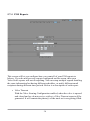
1
Network Video Server User Guide Version 3.4 by Dividia Technologies 09/01/2014 (Blank Page) 2 DISCLAIMER No warranty or representation, either expressed or implied, is made with respect to the contents of this documentation, its quality, performance, merchantability, or fitness for a particular purpose. Information presented in this documentation has been carefully checked for reliability; however, no responsibilities are assumed for inaccuracies. The information contained in this documentation is subject to change without notice. In no event will Dividia Technologies be liable for direct, indirect, special, incidental, or consequential damages arising out of the use or inability to use this product or documentation, even if advised of the possibility of such damages. COPYRIGHT 2002-2014 by Dividia Technologies, L.L.C. All rights reserved. No part of this publication may be reproduced, transmitted, transcribed, stored in a retrieval system, or translated into any language in any form by any means without the written permission of Dividia Technologies, L.L.C. 3 (Blank Page) 4 Contents 1 Preface 1.1 Package Contents …...................................................................... 7 1.2 Specifications …............................................................................ 8 1.3 Limited Warranty …....................................................................... 8 1.3.1 Warranty Length ........................................................... 8 1.3.2 Who is protected? …..................................................... 9 1.3.3 What is and is not covered? …...................................... 9 1.3.4 What we will and will not pay for …............................ 9 1.3.5 Contact Information ….................................................. 9 2 NVS Introduction …................................................................................... 11 3 Live Video Monitoring …........................................................................... 13 3.1 3.2 3.3 3.4 3.5 3.6 3.7 1 – Camera Display …................................................................. 14 4 – Camera Split Display …......................................................... 14 8 – Camera Split Display …......................................................... 15 9 – Camera Split Display …......................................................... 15 16 – Camera Split Display …....................................................... 15 Full Screen Display ….................................................................. 15 Auto Scan …................................................................................. 16 4 Playback of Recorded Video …................................................................. 17 4.1 4.2 4.3 4.4 4.5 Overview ….................................................................................. 17 Video Preview ….......................................................................... 18 Video Player …............................................................................. 18 Video Download …...................................................................... 18 Filters …...................................................................................... 19 5 Setting up your NVS System …................................................................. 21 5.1 System Setup …........................................................................... 22 5.1.1 NVS Name …............................................................... 22 5.1.2 Recording Frame Rate …............................................. 22 5.1.3 Auto Scan Interval …................................................... 23 5.1.4 Email Setup ….............................................................. 23 5.1.5 Digital Output (Optional) …........................................ 23 5.2 Device Setup ..….......................................................................... 24 5.2.1 Input Setup …............................................................... 24 5.2.2 Find Utility ….............................................................. 25 5 5.3 User Setup …................................................................................ 26 5.3.1 Overview …................................................................. 26 5.3.2 Setup a New User ….................................................... 26 5.3.3 Edit User Access Rights ….......................................... 26 5.3.4 Cloning User Rights …............................................... 28 5.3.5 Delete a User …........................................................... 28 5.3.6 Applying User Changes …........................................... 28 5.4 Camera Setup …........................................................................... 29 5.4.1 General …..................................................................... 29 5.4.2 Video …........................................................................ 30 5.4.3 PTZ ….......................................................................... 32 5.5 Date / Time Setup ….................................................................... 33 5.6 Network Setup …......................................................................... 34 5.7 Reports 5.7.1 5.7.2 5.7.3 5.7.4 …..................................................................................... 35 Summary ….................................................................. 35 Camera Activity …....................................................... 36 Alarm (Optional) …...................................................... 37 POS Reports (Optional) …........................................... 38 5.8 POS (optional) ….......................................................................... 40 5.8.1 JWS / Apex ….............................................................. 41 5.8.2 Valve Sensing ….......................................................... 42 5.8.3 Scale Sensing ….......................................................... 43 5.8.4 PTZ Control Configuration …..................................... 44 5.8.5 Digital Output Configuration …................................... 45 6 Utilities 6.1 6.2 6.3 6.4 ….................................................................................................... 47 Export …...................................................................................... 47 Reports …..................................................................................... 48 JWS Ticket Search (Optional) …................................................. 49 Support …..................................................................................... 50 7 Remote Access …........................................................................................ 51 7.1 General …..................................................................................... 51 7.2 Mobile Devices …........................................................................ 53 7.2.1 Navigation ................................................................... 54 8 Enterprise Viewer ….................................................................................. 55 8.1 General …..................................................................................... 55 8.2 Log In …...................................................................................... 56 8.3 Jump System Menu …................................................................. 56 8.4 Functions and Features …............................................................. 56 6 Chapter 1 Preface Dividia Technologies Network Video Recorder (NVS) is the latest in digital surveillance technology. It enables you to more easily manage and catalog your video information. Video recording is controlled by Dividia Motion Detection Technology. When motion is Detected, it automatically catalogs the information for easy access at a later time. You are no longer required to wade through hours of video to find the information you need. 1.1 Package Contents Dividia Technologies NVS package includes: NVS (Network Video Server) Power Cable Keyboard and Mouse User Manual 7 1.2 Specifications Features Standard HDD 1TB-3TB (contact us for additional options) Raid Mirroring Optional External Storage DVD, HDD, USB Video Compression H.264, MPEG4 Recording Modes Motion, 24/7 FPS per Camera 1-30 Display Modes 1, 4, 8, 9, or 16 Search Modes Time/Date, Transaction Details w/ POS Interface PTZ Support Yes Export Video Yes Field Upgradable Yes Operating System Linux Dimensions Varies Weight Varies AC Power Input 115/230V 1.3 Limited Warranty Dividia Technologies. L.L.C warrants that this product is free of defects resulting from faulty manufacturing or components under the following terms: 1.3.1 Warranty Length Labor is warranted for 12 months from the date of purchase. Replacement products will be warranted for 12 months from the date of purchase All warranted items must be shipped to Dividia Technologies, L.L.C. for work to be completed unless otherwise stated. 8 1.3.2 Who is protected? This warranty is enforceable only by the first consumer purchaser. 1.3.3 What is and is not covered Except as specified below, this warranty covers all defects resulting from faulty manufacturing of this product. The following are not covered by the warranty. 1. Any product on which the serial number has been defaced, modified or removed. 2. Damage, deterioration or malfunction resulting from: Accident, abuse, misuse, neglect, fire, water, lightning or other acts of nature, unauthorized product modification or failure to follow instructions included with the product. Misapplication of service by someone other than the manufacturer's representation. Any shipment damages. (Claims must be filed through carriers) Any other cause that does not relate to a product defect. 3. Cartons, cases, batteries, cabinets or other accessories used with the product. 4. Dividia Technologies, L.L.C. does not warrant that this product will meet your requirements; it is your responsibility to determine the suitability of this product for your purpose. 1.3.4 What we will and will not pay for We will pay labor and material expenses for covered items. We will not pay for the following: 1. Removal or installation charges. 2. Shipping charges. 3. Any incidental charges. 1.3.5 Contact Information 2901 Alta Mere Dr, Suite 800 Fort Worth, TX 76116 TEL: 866-348-4342 FAX: 817-288-1039 WEB: www.dividia.net 9 (Blank Page) 10 Chapter 2 NVS Introduction Once all connections have been properly made, press the power button located on the front of the NVS system. When the system completes the self-test and normal boot-up procedure, you are presented with a login screen. This login screen keeps unauthorized persons from accessing your video information. There are varying levels of access to your NVS system. By default, the admin account has access to all features of the system. 11 To begin using your system, please login with the default information: Username Password admin admin 12 Chapter 3 Live Video Monitoring After logging into the system, you are presented with the Live Monitoring screen. This screen allows you to view all your cameras in various configurations. 13 There are 5 split display modes to choose from: 1 – Camera Display 4 – Camera Split Display 8 – Camera Split Display 9 – Camera Split Display 16 – Camera Split Display ________________________________ Additional View Controllers Full Screen Display Auto Scan 3.1 1 – Camera Display In this display you are able to monitor a single camera at a time. While in this display you will be presented with a button for each camera 1-16 along the bottom of the viewing area. By clicking one of these buttons that camera will be displayed. 3.2 4 – Camera Split Display In this display you are able to view 4 cameras at a time. The groups of cameras displayed will be 1-4, 5-8, 9-12 and 13-16 depending on the number of cameras supported by your NVS. If all the cameras for a particular group have been disabled, then that button will be inactive. You will not be able to click on an inactive button. If you would like to view one of the cameras in full view, double click on that camera. When you would like to return to the split display double click on the video again. 14 3.3 8 – Camera Split Display In this display you are able to view 8 cameras at a time. This display is only available on systems supporting 8 or more cameras. The groups of cameras displayed will be 1-8 and 9-16 depending on the number of cameras supported by your NVS. If all the cameras for a particular group have been disabled, then that button will be inactive. You will not be able to click on an inactive button. This display is very effective when monitoring several areas at one time. You are able to double click on any camera's video to move that camera to the larger display area. However, the other 7 cameras remain visible for monitoring at the same time. 3.4 9 – Camera Split Display In this display you are able to view 9 cameras at a time. This display is only available on systems supporting 9 or more cameras. The groups of cameras displayed will be 1-9 and 8-16 depending on the number of cameras supported by your NVS. If all the cameras for a particular group have been disabled, then that button will be inactive. You will not be able to click on an inactive button. If you would like to view one of the cameras in full view, double click on that camera. To return to the split display double click on the video again. 3.5 16 – Camera Split Display In this display you are able to view 16 cameras at a time. This display is only available on systems supporting 16 cameras. The group of cameras displayed will be 1-16. If you would like to view one of the cameras in full view, double click on that camera. To return to the split display double click on the video again. 3.6 Full Screen Display Using this button you are able to monitor your cameras in full screen. This allows the camera viewing area to use all the available space on the screen. You are still able to move from split screen to single screen and back while in full screen mode. To exit the full screen display, right click anywhere on the screen. 15 3.7 Auto Scan In each of the camera display modes you are able to turn on Auto Scan. Auto Scan allows you to scan through each of the camera groups continuously. For example, if you are in 1 – Camera Display, Auto Scan will move from Camera 1 to Camera 2, to Camera 3, etc. The Auto Scan interval default is 10 seconds; this can be configured through the system setup. Click on any camera group to exit Auto Scan. 16 Chapter 4 Playback of Recorded Video 4.1 Overview The playback screen allows you to access all recorded video. You are able to retrieve recorded video by Date and Time. Additionally, you can apply various filters to the search. (see 4.5 Filters) Each filter limits the amount of view you have to review to find exactly what you are looking for. 17 You can view video using the following procedure: 1. Select a camera to view 2. Select any filters you wish to have applied to the search 3. Select a Date and Time 4. Click the Find button. If no video was found for that camera you will receive a prompt notifying you that there is nothing to view. Otherwise, the requested video will begin playing automatically. 4.2 Video Preview The video review area consists of two sections. On the left is the video preview area containing snapshots of the activity that occurred around your desired time. Click on a preview snapshot to begin playing that segment of video. The video will start in the player section to the right. If the video you are looking for is not located in the preview area, you can click the Forward or Back buttons to load another set of 9 previews. By doing this you are able to quickly step through all recorded video for that camera. As an example, you may be looking for the time a car had left your parking lot. You could easily scan through hours of video to determine when the car left, all without the need to watch the entire video. 4.3 Video Player From the player section on the right, you are able to control the video with DVDlike controls. You can Play, Pause, Stop, Rewind and Fast Forward the video. If you would like to see more detail you can click the Full Screen button. While in the Full Screen view only the player is visible. This allows for an optimum viewing experience. When you are ready to exit Full Screen view click the button again. 4.4 Video Download One of the ways to save recorded video from the NVS onto your remote viewing computer is to use the Download button located above the Video Player window. By clicking this button the video currently playing will be downloaded. A new window will open allowing you to name the file and select where you would like it to save. Once you have made your selections click the Save button. Your video will now be downloaded. Note: This download method will only work from a remote computer. This button is not available directly on the NVS. 18 4.5 Filters There are two filters that may be used during a video search or flagged while viewing playback. These filters are: 1. Archive 2. Export Archived Video By selecting this filter using the checkbox above the video player, the currently playing video will be flagged for archive. Archived video will remain on the system indefinitely until it is deleted by the user. If video has been flagged for archive, you may also search for only archived video using the check box beneath the camera search field. Export Video By selecting this filter using the checkbox above the video player, the currently playing video will be flagged for export. Multiple clips can be flagged for export and using the Utilities → Export screen, can be specified for export to CD, DVD, External Hard drive or ZIP file. If video has been flagged for export you may also search for only exported video using the check box beneath the camera search field. 19 (Blank Page) 20 Chapter 5 Setting up your NVS System From the Setup screen you are able to change how your NVS system operates. You are able to Setup the following: 1. System This section contains basic system settings. 2. Device This section allows you to add camera input devices. 3. Users This section allows you to add and remove users from the system. You can also change access rights. 4. Cameras This section allows you to adjust setting specific to the camera 5. Date / Time This section allows you to adjust the Date and Time settings of your NVS. 6. Network This section allows you to adjust your network settings. 7. Report This section allows you to create various reports related to the operation of your NVS. 8. POS This section allows you to setup interfaces between your NVS system and various POS systems. POS System support is sold separately. 21 5.1 System Setup 5.1.1 NVS Name You have the ability to name your NVS. You should pick a name that uniquely describes the system. (Often it may be the physical location) This name can be 32 alphanumeric characters in length. 5.1.2 Recording Frame Rate You are able to adjust the recording frame rate for each of the cameras independently. If you would like to set all the cameras to the same recording frame rate, select the All checkbox. With this box checked you can adjust any camera and the others will follow. The recommended setting is from 2-5 FPS. The higher this setting the less days the NVS will record. 22 You can also configure how many seconds before and after the triggering of the camera you would like to record. You can record a maximum of 2 seconds before the triggered motion. This is useful to see what was going on just before the activity occurred. Recording extra time after the event is useful to maintain continuity throughout multiple events. 5.1.3 Auto Scan Interval Auto Scan allows you to continuously scan through your cameras under the Live Monitoring Display. This is the interval to wait before switching cameras. If this interval is set to 10 seconds and you are in 4 – Camera Split Display, cameras 1-4 would be displayed initially. After 10 seconds those cameras would switch to 5-8. After another 10 second period the cameras would switch to 9-12. This will continue indefinitely or until you select another Display or Camera group. 5.1.4 Email Setup There are certain times when you may want the system to send an email notification. Various reports that you will learn about in a later section, will utilize this setting. In order for the emails to be sent properly, you must first tell it how to send them. You can configure which server to send it through and with what credentials. 5.1.5 Digital Output (Optional) If you purchased the Digital Input/Output Module, then you now have the option of activating certain digital output relays. This will output 12V to whichever outputs you set up. As an example, if you wanted to drive a pair of dry contacts, this would allow you to do so. Prior to using this option, you must select which camera input device these digital inputs and outputs are associated with. 23 5.2 Device Setup 5.2.1 Input Setup In order to record video you must have at least one input device configured on your NVS. An input device would be a Network Device or Network Camera. In order to add a new input Device, you must specify a unique name. Then complete the fields at the bottom of the screen (Type, IP, Username, and Password). 24 5.2.2 Find Utility To find available camera devices on the network that are accessible to the NVS, click the Find button at the bottom right of the Device Window. This will bring up a list of devices that can be added to your NVS. Using the drop down menus you can filter which devices you would like to see (cameras, network devices, NVRs, etc.) as well as the network you would like to search. Devices can then be selected by checking the box to the left of the device name, IP addresses changed and the Dividia Camera defaults applied using the proper checkboxes at the top of the window. Note: The Dividia default option will format the camera to optimally function with the NVS hardware/software. Using this default is highly recommended to ensure the best performance from the camera and the NVS system. 25 5.3 User Setup 5.3.1 Overview From this screen you are able to manage all access to your Dividia Video System. You can create, edit and delete users. You can also change what access rights each user has to your system. 5.3.2 Setup a New User To create a new user, click on the New button at the bottom of the screen. The previous user information will disappear allowing you to input the new user's information. Enter a Username into the appropriate field. Keep in mind that your username and password settings are case-sensitive. Make a note if you are entering them with the CAPS lock enabled or mixed-case lettering. After entering your username, type the password you wish to setup. Type it a second time into the Verify Password box. If the passwords do not match, you will be required to re-enter this information. Once you are finished, click the Apply button. 26 5.3.3 Edit User Rights After the new user has been created, it will be selected in the list of users granted No Access on the screen to the left. To grant this user access to the system; be sure they are highlighted and click the right arrow to move them to the Access list. Next you will want to setup what this user can do on the system. Do this by assigning Server Rights to the user. These rights give you the fine-grained ability to extend or limit access to your system. Below is a description of each right. Additionally, you will want to select which cameras this user is able to access. Server Rights Administrator The Admin right enables special Administrator features on the system. A user that has the Admin right is able to control all aspects of the Setup Screen including System, Users, Camera, Date/Time, and Network. They are also able to access the Utilities and Playback sections. Export The export right allows the user to use the Utilities → Export screen. From this screen, they will be able to export video off the system. If you do not wish for users to take video off-site, you should disable this right. Remote Viewing The remote viewing right allows the user to view the cameras through a web-browser. Without this right, they will get an access denied message. PTZ Control The PTZ Control right allows users to manipulate the Pan, Tilt and Zoom functions of any cameras with this feature on the system. Playback The playback right allows the user to review recorded video. 27 5.3.4 Clone User Rights You are able to create a new user with the exact same rights as another user on the system. Setup a new user as described in 5.3.2 Setup a New User; right click on the created user, a window with all available users will appear, select the user whose attributes you would like to copy from the User List. Click the OK button. Your new user will have the same attributes as the user you have cloned. 5.3.5 Delete / Suspend a User To delete a user, select the username in the User List on the screen. Next, click the Delete button. You will be prompted to make sure you would like to delete the user. If you do, click the OK button. If this was a mistake and you do not want to delete the user, click the Cancel button. You can also suspend a user from system access by selecting their login in the Access list, clicking the left arrow and moving them to the No Access list on the right. If you ever need to reinstate this user, click the right arrow to grant them access once again. 5.3.6 Applying User Changes When you have finished making changes to a user, do not forget to apply those changes by clicking the Apply button. If you do not click the Apply button, the system will prompt to make sure you do not intend to lose your changes. 28 5.4 Camera Setup This section allows you to customize all per-camera settings. To select a camera, click on the corresponding Camera number. This will load the various settings for the camera. For each camera, there are three tabs containing settings: General, Video, and PTZ. 5.4.1 General If you do not have a camera attached to this position, it is best to disable the camera. You can disable the camera by un-checking the Enable check box. This will completely turn off the camera preventing it from using any system resources. If you would like to give each camera a unique name, you can enter it into the Camera name field. Be sure to only use alphanumeric characters. A maximum of 32 characters are allowed for each camera name. Next, select which Camera input Device you would like to use for this camera. Your NVS system supports network cameras that run over a standard 29 ethernet network and are IP addressable. If you have a question regarding a particular camera and its compatibility, please contact Customer Support. Other options include specifying the font size for the camera overlay information and audio enable (if the camera is capable of recording an audio stream). The camera can also be opened directly in a web browser for further configuration by clicking Open Camera Browser. This option is only available on remote connections and can not be used directly on the NVS. 5.4.2 Video Preview If you would like to see a live preview of your camera as you are making changes, click the Preview check box. Any changes you make that affect how the camera looks can be viewed in real-time. 30 Recording Settings To modify how your cameras behave when detecting motion activity, change the Record Type. The 4 recording options are explained below: Always This will disable any motion detection and always record, 24/7, for this camera. Motion This will utilize motion detection algorithms to eliminate hours of unnecessary video. With this setting enabled, no video will be recorded unless there is activity in front of the camera. This allows you to view incidents of importance and more efficiently use your time. Alarm This setting allows you to hook a physical relay into your video system. For instance, if you would like to record only when a door is opened, you would use this feature. Never This will disable any motion detection and never record. The camera will still be available for viewing in Live mode. The motion sensitivity setting determines at what point the NVS system will start recording when there is activity. If you are recording too much, then increase this setting. Increasing this threshold will make it so more activity is needed to begin recording. 31 5.4.3 PTZ Pan/Tilt/Zoom cameras allow you to control the camera remotely within the NVR software. If this is a PTZ camera, check the Enable box. We currently support Pelco, Zavio, ACTi, Axis, and Panasonic PTZ cameras directly, but can configure a system to meet a majority of custom applications if needed. Select the protocol that corresponds to your camera brand/model. If you have questions regarding the compatibility and setup of your PTZ camera please call Customer Support. 32 5.5 Date / Time Setup It is very important that you have the correct date and time set on your system. If this is not set correctly, then you will have difficulty finding the video information you are looking for. There are two ways to set the time on your system. If the Sync time automatically with a time server check box is selected, your system will contact the time server listed in the text box (once every hour) to obtain the current time. The second way date/time may be set is to un-check the Sync Time box and manually select the date and time. This is most useful if your system is not connected to the Internet, or you would like to sync the time manually to another system such as a POS system. 33 5.6 Network Setup If you would like to access your system remotely, then you will need to enter the correct network settings for your local network. This information can be obtained from your local System Administrator. The default setting is to Automatically Obtain IP settings with DHCP. If you have a DHCP server on your local network that hands out addresses, then this is the easiest configuration. However, you will need to know the address before you will be able to connect remotely. The second way is to Statically set the IP address. This allows you to manually specify the IP Address, Subnet Mask, Default Gateway Address, and the Primary DNS Server. Once completed, do not forget to click the Save button. This will apply any changes that have been made. Under the Advanced Network Settings the public port should match the public port that is opened in your router/firewall. This is set to 80 as a default. The Public RTSP Port should be set to 554 to allow remote streaming of the network cameras to your multiple computers/devices. 34 5.7 Reports Your NVS system supports a number of different reports. Reports contain information about your system and its performance. By default, all NVS systems contain a summary report that will provide you with event totals. Additionally, you can configure Camera Activity reports. If you purchased any of the optional POS Modules, a POS Reports tab will also be available. All of these reports can be scheduled. The camera activity report will only report on activity if it is within the defined schedule. You can specify up to 3 different email addresses that will be notified for each report type. 5.7.1 Summary This is an email only report. It will not store any photos or video locally on the system. The schedule you specify is not a range. It is the exact time you would like the report to run and be emailed. You can report totals or detailed statistics. The detail will contain line items for each event matching your selected option. There are three main pieces of information available for this report. 1. Event Total/Detail This will show you the number of events broken down by camera that 35 your system recorded. Each time a camera senses activity it will log an event. If you choose to see the detail, it will tell you which camera, what time, and how long the event lasted. 2. Report Total/Detail This will show you the number of reports that were generated from the POS Module. For instance, you can view a detailed list of which Scale Reports were generated and what information was contained in them (tare weight, etc). 3. Ticket Total / Detail This will show you the number of tickets captured from your Apex system, if you purchased the POS Module and are using the JWS/Apex type. 5.7.2 Camera Activity This is an email only report. It will not store any photos or video locally on the system. This report will notify you when there is activity on a certain camera. The default schedule for this report is everyday all the time. 36 5.7.3 Alarm (Optional) If you purchased the Digital Input Output Model, then you will have access to alarm reports. You can setup these reports to trigger based on a change in one of the digital input lines. This is very useful for wiring your NVS system to an Alarm and force a snapshot when a zone trips. 37 5.7.4 POS Reports This screen will let you configure how you want all of your POS reports to behave. If you do not have any reports configured on this screen, then your Valve/Scale reports will not do anything. You can setup multiple reports detailing the same information but having different schedules, or notify different email recipients during different time periods. Below is a description of each report. Valve Timeout With the Valve Sensing Configuration enabled, when the valve is opened and closed and we do not receive a ticket, a Valve Timeout report will be generated. It will contain the photo(s) of the truck as it was getting filled. 38 Lost Connection with Scale If your NVS is not able to communicate with the scale, then this report will be generated, Restored Connection with Scale Upon successfully reconnecting with a scale, this report will be generated to notify you of the change. Tare Weight Contamination As the scale starts to increase from 0 (zero) weight, your NVS will monitor it. Once the scale settles for the first time, we record this as the Tare weight. If this weight is above your preconfigured threshold, then this report will be generated. It will tell you what your threshold is and what the actual Tare weight reading was. No Ticket If a truck was on the scale and drives off, but your NVS never receives a ticket from the Apex system, then a No Ticket report is generated. If we generated a Tare Weight Contamination report, then we will skip this report so you don't get a false alarm if you told the truck to go unload the old product. Gross Ticket Weight Mismatch Once a ticket is generated, we will compare the weight on the ticket with our maximum weight reading on the scale. If those weights differ by more than your preconfigured threshold, then this report will be generated. Overweight Truck Your NVS system will monitor the scale weight as you are filling the product. If the maximum weight on the scale goes above your overweight threshold, an overweight report will be generated. 39 5.8 POS (Optional) From here you can configure various POS systems with Text Overlay. Select the supported POS type from the POS drop down menu. If this POS supports Serial communication, then you will need to configure the Serial Settings section which contains standard Serial port settings such as baud rate, etc. If this POS supports Network communication, then you will need to configure the Network Settings section. For network configuration of the system, select which port you would like the NVS to listen on. Then, on your POS system, set up a generic text-only driver to print to the NVS IP and port combination you have established. Your NVS will overlay any information sent to this port over the network. You can choose to associate several cameras with a POS transaction. Additionally, you can elect to overlay the POS information directly on the image. 40 5.8.1 JWS / Apex (Optional) For JWS systems, there will be additional JWS Configuration options available. Since JWS tickets do not take up much space, you can specify a ticket count to keep on the system before erasing old tickets. You can also share the tickets on the network. From another machine on the network, you should be able to access this share by going to //IP.OF.DVS.SYSTEM/tickets. This is a read -only directory that contains the same ticket information as the DVS system has in its catalog. The following JWS ticket format is supported. By using an XML format, we can provide you with far more flexibility and allow for finer grained searching. XML Format <ticketentry> <ticket>*10</ticket> <uniqueid>*757</uniqueid> ... </ticketentry> A new condition flag can be set if you want to selectively skip certain ticket types. In this example, if you had a status field, you could skip generating a ticket on our side when the status field (*5) equals A or S. You can specify the following format <ticketentry> <ticket>*10</ticket> <uniqueid>*757</uniqueid> <status condition=”A|S” result=”skip”>*5</status> ... </ticketentry> You can now specify a File Format to save the tickets in. You can use a variety of variable placeholders to insert relevant information. %k - Ticket Number 41 %u - Unique ID %r - Reprint ID %i - Scale ID Additionally, you can specify 02 to zero pad a number by a certain amount. So, D%04r would produce D0001 for Reprint ID 1. 5.8. 2 Valve Sensing (Optional) Valve Sensing allows your NVS system to communicate directly with the PLC that controls the valve. You can have a dry contact connected to your NVS that provides a low-voltage signal +12V to the NVS when the valve is either open or closed. As soon as the valve opens, we will take pictures of the truck on the scale. If we have not received a ticket from the Apex system before a user defined timer expires, then we will generate a Valve Alert and save the previously generated pictures associated with this Report. The file format is similar to that of the Apex configuration on the previous page. You can configure the timer to behave in one of two ways. 1. Initiate the timer when the valve closes for the first time. This is useful in Cement installations where loading happens in one place. In other words, the truck never moves. The default timeout of 120 seconds should suffice in this scenario. 2. Initiate the timer when the truck leaves the scale. This option requires that you have Scale Sensing properly configured. This is useful in Asphalt installations where the loading happens on one scale but several different silos. Obviously, the timer should be much shorter ( 0-10 seconds) in this scenario. 42 5.8.3 Scale Sensing (Optional) Scale Sensing is similar to Valve Sensing, however we do not interface with the PLC, but talk directly to the Scale just as your Apex system does. Select the type of scale indicator you will be using on this scale. Your scale indicator should be networkable. If it is not, then contact our Sales Department and they will instruct you on how to convert a traditional indicator into a network-able one. Once you have confirmed that the scale indicator is accessible via TCP/IP (the network), please enter the IP address and TCP Port that it can be accessed on. Below is a listing of the rest of the settings on this screen. These are the criteria used while monitoring the scale output to decide if and when to generate reports. Tare Minimum This is the minimum weight that we will use for a tare weight. This should be set high enough so anything smaller than a truck is not detected on the scale. Tare Maximum This is the maximum weight that the scale will read and still pass information to the NVS. Anything over this threshold will generate a possible Tare Contamination Report. We want to be certain that the trucks are empty before we add our product in as to not mix any product with the material from another company. Weight Decrease Limit When filling a truck on the scale, sometimes the weight will bounce up and down by small amounts 20-40 pounds. This setting determines the amount of weight decrease that should be considered as the truck having left the scale. The default settings is 1000 pounds. Ticket Weight Different Limit This refers to the maximum weight difference between the weight read from the scale and the gross weight field on the ticket. These weights may not always match since the driver may get out of the vehicle. The default is 500 pounds. 43 Maximum Weight Limit If your state regulates a maximum allowable weight through D.O.T. then you can add a limit here. Any truck loaded above this threshold will generate an Overweight Report. Ticket Weight Field The value of this field specified in your Apex XML template will be compared to the maximum weight we receive on the scale. The weight should be in pounds. File Format This determines the format in which files are saved. You may use the special variable %u to insert the unique ID associated with this report. 5.8.4 PTZ Control Configuration (Optional) If you purchased a PTZ (Pan/Tilt/Zoom) camera, you can control it based on certain input from your Apex system. There are two different ways you can set this up depending on if you purchased the Digital Input/Output Module. 1. Template Field You can enter a field that is contained on your Apex XML template. When Apex prints a ticket and sends it to your NVS, we will parse the value for that field and tell the PTZ to go to that preset. For example, if you specify “Silo”, like the screenshot above, and on your ticket we see “<silo>Silo 1</silo>”, then we will tell PTZ (CAM 10) to jump to preset “Silo 1”. This option does not require the addition of the Digital Input/Output Module. 2. Digital Input (requires purchase of the Digital Input/Output module) Using this option, you can control a PTZ based on digital inputs. As you 44 can see in the previous screenshot, specific inputs correspond to certain PTZ presets. A good example would be to wire some relays into your PLC that will send a digital input based on which Silo gate is open. This is very handy for license plate shots at Asphalt facilities. 5.8.5 Digital Output Configuration (Optional) If you purchased the digital input/output module, you now have the ability to control other equipment based on your NVS receiving tickets from Apex. An example of such a scenario would be if you wanted to control a traffic light automatically with your NVS. This setup requires the use of a Moxa VPort to wire everything into. In the screenshot above you can see where you select which digital outputs you would like to tie to this scale. Next, you specify in which conditions you want to open or close the relay associated with that digital output number. You can also specify a timeout after receiving the ticket to revert such a change (change the light red again). 45 (Blank Page) 46 Chapter 6 Utilities This section contains various utilities you might find useful for your system. With these utilities, you will be able to export video and perform several other important tasks. 6.1 Export 47 To export video from your Digital Video System, you should first decide what video you would like to export. You can do this in two ways: 1. First, select the desired camera(s)s to export. Second, choose the date and time range of the video. 2. You can also export any video you intentionally flagged while reviewing the video through Playback. Finally, select which device to export to from the drop-down menu and click the Export button. Follow the onscreen prompts to complete the export. When finished, you should have a new CD, DVD, External Hard Drive file, or Zipped file containing the desired video(s). To playback the video(s), select a playlist for a camera. 6.2 Report If your NVS system generates Reports that may save files (POS Style Reports), then you can search them here. You can search by the type of report and the date/time that it was generated. This will allow you to review the camera shots associated with that report. 48 6.3 JWS Ticket Searching You can search by JWS ticket numbers with this screen. Type in the ticket number you are looking for and click Find. A preview of 9 tickets surrounding the ticket number you searched for will appear on the left side of the screen. To view a particular ticket, click on that preview shot. The ticket will load in the right part of the screen. You can associate several different cameras with a JWS ticket. If more than one camera is associated with the ticket, they will be numbered sequentially above the image on the right. Just click on the radio button for that camera to display various shots of the ticket. You are also able to zoom in on certain areas of the image. Just click and drag a box around any area that you would like to view more closely. To return to your normal view, just click anywhere on the image. 49 6.4 Support This section contains a number of technical support utilities. These are often used in diagnosing problems remotely when speaking with Customer Support. 50 Chapter 7 Remote Access 7.1 General To access the system remotely, you must first have the Remote Viewing right enabled under the Setup → Users ᅠscreen. Once that is set, you can access your DVS by simply opening a web-browser (Internet Explorer, Firefox, Chrome, Safari, etc) and going to http://IP.OF.DVS.SYSTEM/ and clicking Go. 51 You have two options to view your NVS system remotely. The first option is the Lite Viewer. This is a web-based HTML viewer that allows you to quickly view your NVS system live and now has the ability to playback footage as well. You can access this by clicking on the Lite text, next to your company/residence link at http://video.dividia.net If you would like to export recorded footage or access any of the configuration sections of your NVS, you must run the Standard Viewer. You can access this by clicking on the full name text, next to your company/residence link at http://video.dividia.net 52 7.2 Mobile Devices Dividia's NVR software is web based allowing you to access your system whenever you have and internet connection. There is no need for an additional app to download. Just access your DVR as you would on any computer by simply opening a web-browser (Internet Explorer, Firefox, Chrome, Safari, etc) and going to http://IP.OF.DVS.SYSTEM/ and clicking Go. You will automatically be forwarded to the mobile version of the Lite Viewer after clicking on n the full name text, next to your company/residence link and entering the proper login information. Multi-camera view will display the first set of 4 cameras. 53 7.2.1 Navigation There are various was to navigate through your cameras. The following will apply in both portrait and landscape views. 1. Swipe left and right to view the next set of 4 cameras (dependent upon the number of cameras supported by your NVS) 2. Tap on a camera to enlarge the view to full screen Tap again to go back to multi-camera view To log out of your mobile session, turn the device into portrait view and select the logout button located toward the bottom of the screen 54 Chapter 8 Enterprise Viewer (Optional) 8.1 General The Enterprise Viewer allows you to view and manage your multiple NVRs using a single interface. It also allows you to configure multiple views containing only the cameras you would like to see together. 55 8.2 Log In This is a web-based HTML viewer that allows you to quickly view your NVS systems. You can access Enterprise Viewer by clicking on the Launch Viewer text, toward the top of the page on your company/residence page at http://video.dividia.net 8.3 Jump System Menu The Jump System drop down menu is located below the split display button on the right of the screen. Using this menu you can jump from you current system to any other connected and configured NVR. 8.4 Functions and Features The basic functionality and feature set of the Enterprise Viewer is similar to the Standard viewer in most ways. The main difference is the ability to link multiple NVRs and create custom views using any camera, configured on any system. 56