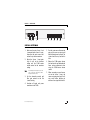
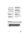
1
model 2500 CONGRATULATIONS Congratulations for choosing a Directed Audio five-band equalizer from Directed Electronics. Directed has been the industry leader in high-quality mobile audio and security since 1990, and with the introduction of the Directed Audio 2500 five-band equalizer, Directed continues to set new standards of performance, reliability and affordability in the mobile electronics industry. Featuring separately adjustable front and rear crossovers, active gain pream- plifiers and three-source input capability, the Directed Audio 2500 five-band equalizer will integrate with the most sophisticated of mobile audio/video systems and will excite and delight the mobile sound enthusiast with years of high-quality audio reproduction. The Directed Audio 2500 five-band is covered by two-year limited warranty. Be sure to retain your original sales receipt, and refer to the warranty section of this guide for full details about your coverage. TABLE OF CONTENTS Limited Two-Year Consumer Warranty . . . . . . . . . . . . . . . . . . . . . . . . .3 Features . . . . . . . . . . . . . . . . . . . . . . . . . . . . . . . . . . . . . . . . . . . .4 Warning . . . . . . . . . . . . . . . . . . . . . . . . . . . . . . . . . . . . . . . . . . . . .4 Installation Guidelines . . . . . . . . . . . . . . . . . . . . . . . . . . . . . . . . . . .5 Intiial Settings . . . . . . . . . . . . . . . . . . . . . . . . . . . . . . . . . . . . . . . . .6 Control Panel Features . . . . . . . . . . . . . . . . . . . . . . . . . . . . . . . . . . .6 Rear Panel Features . . . . . . . . . . . . . . . . . . . . . . . . . . . . . . . . . . . . .8 Crossover and Filter Adjustments . . . . . . . . . . . . . . . . . . . . . . . . . . . .9 System Diagram . . . . . . . . . . . . . . . . . . . . . . . . . . . . . . . . . . . . . . .10 Specifications . . . . . . . . . . . . . . . . . . . . . . . . . . . . . . . . . . . . . . . . .11 2 © 2002 Directed Electronics, Inc LIMITED TWO-YEAR CONSUMER WARRANTY Directed Electronics, Inc. promises to the original purchaser, to replace this product should it prove to be defective in workmanship or material under normal use, for a period of two years from the date of purchase by the dealer as indicated by the date code marking of the product PROVIDED the product was installed by an authorized Directed dealer. During this two-year period, there will be no charge for this replacement PROVIDED the unit is returned to Directed, shipping pre-paid. If the unit is installed by anyone other than an authorized Directed dealer, the warranty period will be one year from the date of purchase by the dealer as indicated by the date code marking of the product. During this one-year period there will be no charge for this replacement PROVIDED the unit is returned to Directed, shipping pre-paid. This warranty is non-transferable and does not apply to any unit that has been modified or used in a manner contrary to its intended purpose, and does not cover damage to the unit caused by installation or removal of the unit. This warranty is void if the product has been damaged by accident or unreasonable use, neglect, improper service or other causes not arising out of defects in materials or construction. ALL WARRANTIES INCLUDING BUT NOT LIMITED TO EXPRESS WARRANTY, IMPLIED WARRANTY, WARRANTY OF MERCHANTABILITY, FITNESS FOR PARTICULAR PURPOSE, AND WARRANTY OF NON- © 2002 Directed Electronics, Inc INFRINGEMENT OF INTELLECTUAL PROPERTY ARE EXPRESSLY EXCLUDED TO THE MAXIMUM EXTENT ALLOWED BY LAW, AND DIRECTED NEITHER ASSUMES NOR AUTHORIZES ANY PERSON TO ASSUME FOR IT ANY LIABILITY IN CONNECTION WITH THE SALE OF THE PRODUCT. DIRECTED HAS ABSOLUTELY NO LIABILITY FOR ANY AND ALL ACTS OF THIRD PARTIES INCLUDING ITS AUTHORIZED DEALERS OR INSTALLERS. Unit must be returned to Directed, postage pre-paid, with: consumer’s name, telephone number, and address, authorized dealer’s name and address, and product description. IN ORDER FOR THIS WARRANTY TO BE VALID, YOUR UNIT MUST BE SHIPPED WITH PROOF OF INSTALLATION BY AN AUTHORIZED DIRECTED DEALER. ALL UNITS RECEIVED BY DIRECTED FOR WARRANTY REPAIR WITHOUT PROOF OF DIRECTED DEALER INSTALLATION WILL BE COVERED BY THE LIMITED ONE-YEAR PARTS AND LABOR WARRANTY. Note: This warranty does not cover labor costs for the removal and reinstallation of the unit. BY PURCHASING THIS PRODUCT, THE CONSUMER AGREES AND CONSENTS THAT ALL DISPUTES BETWEEN THE CONSUMER AND Directed SHALL BE RESOLVED IN ACCORDANCE WITH CALIFORNIA LAWS IN SAN DIEGO COUNTY, CALIFORNIA. 3 FEATURES Five-band graphic equalizer with 18dB boost/cut. Switched input selector for two signal sources. Dual-function volume/fader control knob. Built-in remote output with turn-on delay for switching on amplifiers. Dedicated subwoofer output with adjustable low-pass crossover. 30 volts MOSFET switching power supply. Master volume control drives 4V RMS (front/rear) and 6V RMS (sub out). Gold-plated RCA input/output jacks. Half-din chassis for ease of installation. WARNING High-powered car audio systems may produce sound pressure levels that exceed the threshold at which hearing loss may result. 4 They may also impair a driver’s ability to hear traffic sounds or emergency vehicles. Use common sense and practice safe listening habits when listening to or adjusting your audio system. © 2002 Directed Electronics, Inc INSTALLATION GUIDELINES 1. Read this manual carefully and in its entirety before installing this equalizer. ground and moving parts that can tangle the wires such as heater controls or wiper motors. 2. Always disconnect the battery or remove the fuses for circuits you will be working on. 6. Route all power and signal cables as far as possible from other vehicle wiring harnesses. Loom when appropriate. 3. Check for clearance of any hazards such as hoses, heater core, or brake lines before mounting the equalizer to any panels in the vehicle. 4. Mount the equalizer in a location that is easy to access and won't be distracting to vehicle operation while making adjustments. 5. Route all power wires and audio cables away from sharp metal edges that can cause shorts to © 2002 Directed Electronics, Inc 7. It is recommended that the equalizer be grounded directly to the chassis of the Source 1 head unit. The Source 1 head unit should be grounded at a chassis point (preferably scraped sheet metal) other than the factory head unit ground wire or under dash brackets 8. Use only the supplied machine screws to mount the equalizer or damage to the circuitry could occur. 5 REAR PANEL FEATURES Power Connector 1. Remote Turn On Output - This output is intended to be the remote turn on for the system amplifiers and has a built in delay. Two to three seconds after the 2500 receives a (+)12V turn on signal, it will send a (+)12V turn on signal to the amplifiers. This feature is designed into the 2500 to eliminate system turn on pops that can occur when several components turn on at the same time. 2. (+) 12V Constant Power - This is the main power input for the 2500 and must be connected to a (+)12V constant power supply. DO NOT connect this to a switched (+)12V source or the system may pop when the key is turned off. 3. Remote Turn On Input - This is the input for turning on the 2500. It should be connected to the (+)12V remote turn on output of the system head unit. The 2500 has a built in turn off delay to prevent turn-off pops. When the remote in signal from the head unit shuts off, the amplifiers will turn off immediately and the 2500 will stay on for two to three seconds before turning off. This feature is designed into the 2500 to eliminate system turn off pops that can occur when several components 6 turn off at the same time. DO NOT connect this to a (+)12V constant power supply. 4. Ground - Connect this terminal to a quality ground location (preferably the chassis of the head unit) which must itself be properly grounded to the vehicle chassis. It is not recommended that the factory radio ground be used for any audio components. 5. Power Fuse - This fuse protects the 2500's on-board electrical components. Never replace this fuse with one of higher value or damage to the 2500 could occur and result in loss of your warranty. 6. Front Amplifier Output - These are output jacks for sending the audio signal to the front amplifier. 7. Rear Amplifier Output - These are output jacks for sending the audio signal to the rear amplifier. 8. Subwoofer Amplifier Output - These are output jacks for sending the audio signal to the subwoofer amplifier. 9. Source 2 Input - This is the input for the secondary source unit. 10. Source 1 Input - This is the input for the main source unit. © 2002 Directed Electronics, Inc FIGURE 1—REAR PANEL ATC 3A 1 2 3 4 5 6 7 8 9 10 INTIIAL SETTINGS 1. Make sure the main Source 1 unit is connected to the Source 1 inputs, then adjust the main source units volume to just below maximum. 2. Adjust the Source (top of unit) to setting and the volume control to setting. NOTE: 1 input gains the minimum 2500 master the maximum If connecting more than one input source to the 2500, use the Source 1 gain controls to match the input level of both sources. 3. Set the subwoofer controls and filter gain controls to the flat (center) setting. 5. Turn the system on and increase the gain on the source one inputs until audible distortion can be heard. The system should be very loud at this time. 6. Reduce the 2500 master volume level and test for well balanced and linear volume adjustment when using the 2500 master volume control. 7. When connecting a second source unit to the Source 2 input, the source one input gains (top of unit) may need further adjusting to achieve a close signal level match. 4. Complete all signal and power connection to the 2500. © 2002 Directed Electronics, Inc 7 CROSSOVER AND FILTER ADJUSTMENTS The crossover and filter gain adjustments can be performed two different ways, by using a piece of audio test equipment called an RTA (Real Time Analyzer) or by listening to a familiar piece of music. The RTA is most commonly used to achieve the flattest possible system response in preparation for a sound off competition. Although an RTA may help in setting a flat system response it does not ensure the unit is tuned for your personal listening preferences. When setting the 2500 filter and gain controls using a familiar piece of music, adjustments can be made according the way you like the music to sound in relation to the vehicles acoustics and the type of drivers in the system. 1. Leave the subwoofer controls and the five filter gain controls to the flat (center) position. 2. If the dedicated subwoofer output is being used, turn off any active subwoofer crossovers in the subwoofer amplifier. NOTE : When interfacing with Directed class d amplifiers with non-defeatable Low-pass crossovers adjust the amplifiers crossover point to its highest frequency setting. 3. Adjust the crossover point and subwoofer volume using the subwoofer controls (knobs four and five on the front panel) so the subwoofer blends with the satellite speakers. When set properly the bass should not be localized and voices should not be heard through the subwoofers. 4. Fine tune the system sound using the subwoofer volume control and the five filter gain controls for different tastes or audio material. 5. After adjusting the system for the best sound quality use the equalizers master volume to adjust overall volume of the system. CONTROL PANEL FEATURES 1. Master Volume/Fader Control - The master volume/fader control knob is a retractable dual-function control that extends when needed for adjustments and retracts when not in use. To extend and retract the knob, press and release it into the 8 control panel; it will extend or retract with each press. Volume - The master volume/fader control knob is set to the volume position when it is initially extended. It controls the overall © 2002 Directed Electronics, Inc volume of the system and affects all line level outputs to the amplifiers. Fader - To set the master volume/ fader control knob to the fader position, pull gently on it until a notched position is reached. It will then control the front-to-rear balance of the front and rear RCA output jacks. WARING! DO NOT use excessive force when using this knob or damage to its release mechanism may result. 2. Power On/Off LED - This LED will be illuminated when the 2500 is on. 3. Input Source Switch - The input source switch selects between Source 1 and Source 2 inputs. 4 Subwoofer Volume Control: The subwoofer volume control knob controls the volume of the dedicated subwoofer output. 5. Subwoofer Frequency Control - The subwoofer frequence control knob controls the low-pass crossover frequency for the dedicated subwoofer output between 30300Hz at 12dB/octave. 6. Frequency Controls - The frequency control knobs control the gains for their respective frequencies. The center position is flat with a maximum +18dB and -18dB adjustment capability. FIGURE 2—CONTROL PANEL 1 2 3 © 2002 Directed Electronics, Inc 4 5 6 9 SYSTEM DIAGRAM ATC 3A GROUND REMOTE IN (+)12V CONSTANT REMOTE OUT To Front Amp To Rear Amp To Sub Amp To Source 2 To Source 1 10 © 2002 Directed Electronics, Inc SPECIFICATIONS Directed model 2500 Filter Frequencies 60Hz,125Hz,500Hz,1 kHz,12 kHz Boost/Cut 18dB/octave maximum Crossover/Range 12dB/octave low pass/variable 30-300Hz Signal-to-Noise Ratio 90dB @ 1 Volt input Frequency Response 20Hz-60kHz, +/- 1.0dB Maximum Output Voltage 4V RMS front/rear outputs 6V RMS subwoofer output Output Impedance 500 ohm Gain (all filters set flat) 1V in = 2V (front/rear), 6V (sub) Total Harmonic Distortion < 0.05% Stereo Separation 75dB @ 1kHz Input Sensitivity 50mv - 4.0V RMS (fixed inputs) 50mv - 10V RMS (variable input) Input Impedance 27k ohms Operating voltage/fuse 11-15V negative ground/3A ATC Remote Out 500mA @ 11.5V Size (H x W x D) 1"x 7"x 4-3/4" © 2002 Directed Electronics, Inc 11 The company behind this system is Directed Electronics, Inc. Since its inception, Directed has had one purpose, to provide customers with the finest vehicle security, car stereo products, rear seat entertainment, and accessories available. The recipient of more than 20 patents in the field of advanced electronic Directed Electronics, Inc. Vista, California 92083 www.directed.com technology, Directed is ISO 9001 registered. Directed® is committed to delivering world-class quality products and services that excite and delight our customers. Directed is a proud member of Quality Directed products are sold and serviced throughout North America and around the world Call 800 274 0200 for more information about our products and services 12 © 2002 Directed Electronics, Inc. - All rights reserved - G44520 05/02 © 2002 Directed Electronics, Inc