1
MIXING CONSOLE
Owner’s Manual
Mode d’emploi
Bedienungsanleitung
M
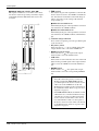
FCC INFORMATION (U.S.A.)
1. IMPORTANT NOTICE: DO NOT MODIFY THIS UNIT! This product, when installed as indicated in the instructions contained in this manual, meets FCC
requirements. Modifications not expressly approved by Yamaha may void your authority, granted by the FCC, to use the product.
2. IMPORTANT: When connecting this product to accessories and/or another product use only high quality shielded cables. Cable/s supplied with this product MUST
be used. Follow all installation instructions. Failure to follow instructions could void your FCC authorization to use this product in the USA.
3. NOTE: This product has been tested and found to comply with the requirements listed in FCC Regulations, Part 15 for Class “B” digital devices. Compliance with
these requirements provides a reasonable level of assurance that your use of this product in a residential environment will not result in harmful interference with
other electronic devices. This equipment generates/uses radio frequencies and, if not installed and used according to the instructions found in the users manual, may
cause interference harmful to the operation of other electronic devices. Compliance with FCC regulations does not guarantee that interference will not occur in all
installations. If this product is found to be the source of interference, which can be determined by turning the unit “OFF” and “ON”, please try to eliminate the
problem by using one of the following measures: Relocate either this product or the device that is being affected by the interference. Utilize power outlets that are on
different branch (circuit breaker or fuse) circuits or install AC line filter/s. In the case of radio or TV interference, relocate/reorient the antenna. If the antenna lead-in
is 300 ohm ribbon lead, change the lead-in to coaxial type cable. If these corrective measures do not produce satisfactory results, please contact the local retailer
authorized to distribute this type of product. If you can not locate the appropriate retailer, please contact Yamaha Corporation of America, Electronic Service
Division, 6600 Orangethorpe Ave, Buena Park, CA 90620
The above statements apply ONLY to those products distributed by Yamaha Corporation of America or its subsidiaries.
ADVARSEL!
Lithiumbatteri—Eksplosionsfare ved fejlagtig
håndtering. Udskiftning må kun ske med batteri
af samme fabrikat og type. Levér det brugte
batteri tilbage til leverandoren.
VARNING
Explosionsfara vid felaktigt batteribyte. Använd
samma batterityp eller en ekvivalent typ som
rekommenderas av apparattillverkaren.
Kassera använt batteri enligt fabrikantens
instruktion.
VAROITUS
Paristo voi räjähtää, jos se on virheellisesti
asennettu. Vaihda paristo ainoastaan
laitevalmistajan suosittelemaan tyyppiin. Hävitä
käytetty paristo valmistajan ohjeiden
mukaisesti.
NEDERLAND
THE NETHERLANDS
● Dit apparaat bevat een lithium batterij voor geheugen
back-up.
● This apparatus contains a lithium battery for memory
back-up.
● Raadpleeg uw leverancier over de verwijdering van de
batterij op het moment dat u het apparaat ann het einde
van de levensduur afdankt of de volgende Yamaha Service
Afdeiing:
Yamaha Music Nederland Service Afdeiing
Kanaalweg 18-G, 3526 KL UTRECHT
Tel. 030-2828425
● For the removal of the battery at the moment of the
disposal at the end of the service life please consult your
retailer or Yamaha Service Center as follows:
Yamaha Music Nederland Service Center
Address: Kanaalweg 18-G, 3526 KL
UTRECHT
Tel: 030-2828425
● Gooi de batterij niet weg, maar lever hem in als KCA.
● Do not throw away the battery. Instead, hand it in as small
chemical waste.
Important Information
Read the Following Before Operating M2500
Warnings
• Do not allow water to enter this unit or allow the
unit to become wet. Fire or electrical shock may
result.
• Connect this unit’s power cord only to the
power supply unit, and connect the power supply unit to an AC outlet of the type stated in this
Owner’s Manual or as marked on the power
supply unit. Failure to do so is a fire and electrical shock hazard.
• Do not scratch, bend, twist, pull, or heat the
power cord. A damaged power cord is a fire and
electrical shock hazard.
• Do not place heavy objects, including this unit,
on top of the power cord. A damaged power
cord is a fire and electrical shock hazard. In particular, be careful not to place heavy objects on a
power cord covered by a carpet.
• If you notice any abnormality, such as smoke,
odor, or noise, or if a foreign object or liquid
gets inside the unit, turn it off immediately.
Remove the power cord from the AC outlet.
Consult your dealer for repair. Using the unit in
this condition is a fire and electrical shock hazard.
• Should this power supply be dropped or the
cabinet be damaged, turn the power switch off,
remove the power plug from the AC outlet, and
contact your dealer. If you continue using the
unit without heeding this instruction, fire or
electrical shock may result.
• If the power cord is damaged (i.e., cut or a bare
wire is exposed), ask your dealer for a replacement. Using the unit with a damaged power
cord is a fire and electrical shock hazard.
• Do not modify the unit. Doing so is a fire and
electrical shock hazard.
Cautions
• This unit is heavy. Use two or more people to
carry it.
• Hold the power cord plug when disconnecting it
from an AC outlet. Never pull the cord. A damaged power cord is a potential fire and electrical
shock hazard.
• Do not touch the power plug with wet hands.
Doing so is a potential electrical shock hazard.
• Use only the included power supply for this unit.
Using other types may be a fire hazard.
Operating Notes
• The digital circuits of this unit may induce a
slight noise into nearby radios and TVs. If noise
occurs, relocate the affected equipment.
• Using a mobile telephone near this unit may
induce noise. If noise occurs, use the telephone
away from the unit.
• XLR-type connectors are wired as follows:
pin 1: ground, pin 2: hot (+), and pin 3: cold (–).
• Insert TRS phone jacks are wired as follows:
sleeve: ground, tip: send, and ring: return.
• The performance of components with moving
contacts, such switches, rotary controls, faders,
and connectors, deteriorates over time. The rate
of deterioration depends on the operating environment and is unavoidable. Consult your
dealer about replacing defective components.
Keep This Manual For Future Reference.
M2500—Owner’s Manual
iii
Introduction
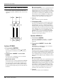
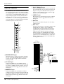
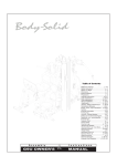
Thank you for purchasing the Yamaha M2500 mixing console. The M2500 is a highly costeffective mixing console that features functionality such as scene memory, PAN control
that is switchable between LR/LCR, and GROUP/AUX FADER FLIP switches. In order to
take full advantage of the M2500’s functionality and ensure trouble-free use, please read
this manual carefully.
Note:
• This manual assumes that you have an understanding of basic mixing console operation and terminology.
• The M2500 series includes five models: M2500-24, M2500-32, M2500-40C, M250048C, and M2500-56C. This manual bases its explanation on the M2500-24. Differences
in the specifications of each models are given in curly brackets { }.
Contents
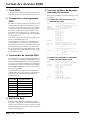
Features of the system............................. 2
Error messages ...................................... 39
Control panel.......................................... 3
Specifications ........................................ 40
Input channel section ......................................... 3
GROUP/AUX master section............................. 9
GROUP/AUX FLIP switch ............................... 14
Stereo/monaural master section ...................... 16
Matrix section ................................................... 18
Monitor section ................................................ 19
Talkback/oscillator section............................... 21
Meter select section........................................... 22
Control section ................................................. 22
Meter bridge...................................................... 24
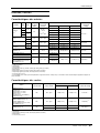
General specifications ...................................... 40
Input/output characteristics ............................ 41
Other ................................................................. 42
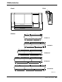
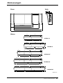
Dimensions ........................................... 43
MIDI data format .................................. 44
MIDI Implementation Chart .................. 45
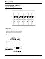
Rear panel............................................. 25
Monaural input channel input/output jacks... 25
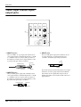
Stereo input channel input/output jacks......... 26
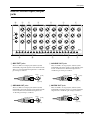
Master section input/output jacks ................... 27
The Scene Memory function ................. 30
What is scene memory? .................................... 30
Modes of the scene memory function ............. 30
Operation in Normal mode ............................. 31
Check mode operation ..................................... 32
Utility mode procedures................................... 34
Control change table ........................................ 36
Mute groups...................................................... 37
About the local control circuit ......................... 38
M2500—Owner’s Manual
1
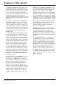
Features of the system
• The M2500-24 {32/40C/48C/56C} provides 24
{32/40/48/56} monaural input modules and
four stereo input modules. It also provides 14
AUX outputs, eight group outputs, stereo output, and monaural output, for a generous total
of 25 output buses. The M2500 is ideal for a
wide range of applications from use as a main
PA mixer to use in installed systems.
• The Scene Memory function allows you to store
the on/off status of each mono/stereo input
channel and GRP/AUX 1–8, STEREO, and
MONO/C output channels as one of 128 scenes.
Scenes can be recalled at any time from the front
panel or via MIDI. In addition, control change
messages can be used to individually switch
these channels on/off from an external device.
• Eight independent matrix outputs are provided.
The GRP/AUX, STEREO, and MONO/C channel output signals and the input signals from
dedicated inputs can be mixed freely, and output
from the eight MATRIX OUT jacks. This is convenient for foldback, or for creating individual
mixes for monitor speakers or amps.
• Eight DIRECT RECALL switches are provided
to allow scene memories 1–8 to be recalled at the
touch of a single button. This allows multiple
channels to be switched on/off quickly.
• Monaural input channels and GRP/AUX output
channels allow you to select not only conventional LR (stereo) output or monaural output,
but also LCR (stereo+center) output. When LCR
output is selected, the level of the center output
signal is also controlled by the PAN control, for
accurate spatial positioning when a three-channel stereo+center playback system is used.
• Monaural input channels provide a 26 dB pad,
high pass filter switch, phase switch, four-band
EQ, and 100 mm full-stroke faders. +48 V phantom power that can be switched on/off individually for each channel is also provided.
• An INSERT I/O jack is provided on each monaural input channel as well as on the AUX 1–6,
GRP/AUX, STEREO, and MONO/C output
channels. This allows you to insert external
effect units as necessary.
• The GROUP/AUX FLIP switch allows the eight
100 mm fader output channels to be used either
for the GROUP or AUX buses. When used for
the AUX buses, all 14 AUX buses can be controlled by 100 mm faders, which is convenient
when using the M2500 as a stage monitor console.
2
M2500—Owner’s Manual
• By changing a setting, the DIRECT RECALL
switches can be used as mute group switches.
Mute group switch settings allow the DIRECT
RECALL switches to individually add/remove
eight sets of mute settings.
• PFL switches are provided on all input channels,
and AFL switches are provided on all master
outputs. In addition, a MASTER PFL switch
allows the master output monitor signal to be
switched between pre/post fader. You can rapidly check the input/output signal sources at a
variety of points.
• The talkback signal and the test tone oscillator
(PINK/10 kHz/1 kHz/100 Hz) can be sent to any
of the AUX 1-2, 2-6, 7-10, 11-14, STEREO, or
MONO/C buses.
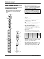
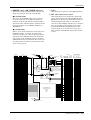
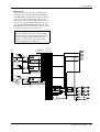
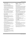
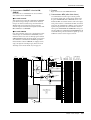
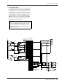
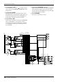
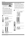
Control panel
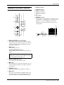
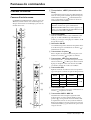
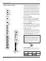
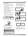
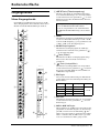
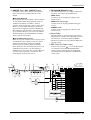
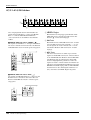
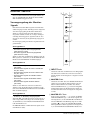
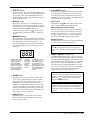
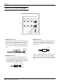
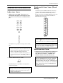
A +48 V (phantom power) switch
Input channel section
This switches the +48 V phantom power supply on/
off for the corresponding channel. When the switch is
pressed in ( ), phantom power is on. At this time
the indicator above the switch will light.
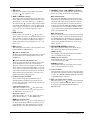
Monaural input channels
The M2500-24 {32/40C/48C/56C} provides 24 {32/
40/48/56} input channels. The specifications of each
input channel are the same for all models of the
series.
+48V
Note: If you wish to use phantom power, make
sure that the rear panel PHANTOM MASTER
switch (page 29) is turned on. (The PHANTOM
MASTER indicator on the meter bridge will light.)
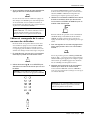
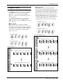
B GAIN control
1
This adjusts the input sensitivity. This control has a
range of –16 dB to –60 dB when the 26 dB pad switch
(3) is off, and a range of +10 dB to –34 dB when the
pad is on.
GAIN
+10
–16
–34
–60
26dB
4
80
2
3
5
C 26 dB pad switch
HI
–15
This attenuates the input signal by 26 dB. When the
switch is pressed in ( ), the pad is on.
+15
HI-MID
400
8k
–15
+15
LO-MID
80
1.6k
–15
+15
D
6
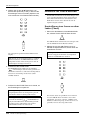
E 80 (high pass filter) switch
This switches the high pass filter on/off. When the
switch is pressed in ( ), the high pass filter is on,
and the frequency range below 80 Hz will be attenuated by an 18 dB/oct curve.
LO
–15
+15
EQ
(phase) switch
This reverses the phase of the input signal. When the
switch is pressed in ( ), the phase is reversed.
7
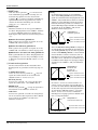
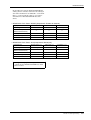
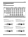
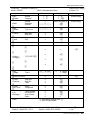
F EQ controls
0
0
10
AUX14
PAN
0
0
0
10
C
AUX2
10
L
ODD
R
EVEN
1-2
ST
3-4
MONO
10
AUX4
0
10
AUX5
LCR
10
10
AUX7
L
ON/EDIT
0
10
AUX8
PRE
0
9
5 NOM
AUX9
0
10
0
10
0
10
0
10
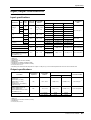
Center frequency
HIGH
Shelving
10 kHz
HIGH-MID
Peaking
400 Hz to 8 kHz
LOW-MID
Peaking
80 Hz to 1.6 kHz
LOW
Shelving
100 Hz
Gain
±15 dB
M
SIGNAL
AUX10
5
10
AUX11
This switches the equalizer on/off. When the switch is
pressed in ( ), the equalizer will be on.
H AUX 1–AUX 14 controls
10 PEAK
10
0
Type
G EQ switch
AUX6
CHECK
ON
0
K
Band
5-6
7-8
8
J
AUX3
PRE
0
This is a four-band equalizer. The type, center frequency, and gain range of each band is shown below.
10
AUX1 PRE
These adjust the level at which the signal of the monaural input channel is set to AUX buses 1 to 14. Nominal level (0 dB) is when the control is at the “▲”
position. The pre-fader signal will be sent to AUX
buses 1/2. For AUX buses 3 to 14, you can use the
PRE switch (9) to switch between pre/post fader.
20
AUX12
30
PRE
40
AUX13
N
0
O
10
AUX14
PAN
50
60
PFL
C
M2500—Owner’s Manual
3
Control panel
If these switches are turned on ( ), the post-EQ prefader signal will be sent to the corresponding AUX
buses. If these switches are turned off ( ), the postfader signal will be sent. Switches are provided to
independently switch three groups of AUX buses: 3–
6, 7–10, and 11–14.
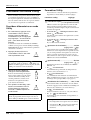
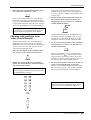
J PAN control
This adjusts the pan or balance of the signal that is
sent from the monaural input channel to the STEREO, MONO/C, or GROUP buses. The function of
the PAN control will change as follows, depending on
the setting of the channel assign switch (K).
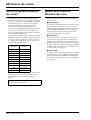
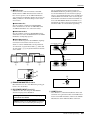
● When the ST switch is on
PAN will adjust the pan of the signal that is sent from
the monaural input channel to the STEREO L/R bus.
Note:
• The LCR switch takes priority over the ST/MONO
switch. When the LCR switch is on, the post-PAN
signal of the monaural input channel will be sent to
the STEREO bus (L/R) and the MONO/C bus regardless of the on/off status of the ST/MONO switch.
When the LCR switch is on, the level of the signals
that are sent to the STEREO bus (L/R) and MONO/C
bus will change in response to movement of the PAN
control as shown in the following diagram.
K Channel assign switches
These switches assign the post-fader post-PAN signal
to the desired bus.
• 1-2/3-4/5-6/7-8 switches
When these switches are on ( ), the signal of the
monaural input channel will be sent to the corresponding GROUP bus (1-2/3-4/5-6/7-8).
• ST (stereo) switch
When this switch is on ( ), the post-PAN signal of
the monaural input channel will be sent to the STEREO bus.
• MONO (monaural) switch
When this switch is on ( ), the signal of the monaural input channel will be sent to the MONO/C bus.
C
R
PAN control
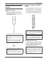
• When the LCR switch is off, the ST/MONO switch
will function as a conventional channel assign
switch. If ST is on, the post-PAN signal of the
monaural input channel will be sent to the ST bus.
If the MONO switch is on, the signal of the monaural input channel will be sent directly to the
MONO/C bus. (The signal sent to the MONO/C
bus will not be affected by the PAN control.) If the
LCR switch is off and the ST/MONO switch is on,
movements of the PAN control will affect the signal levels sent to the STEREO bus (L/R) and
MONO/C bus as shown in the following diagram.
< Response curve 2 >
LCR switch= off
ST switch= on
MONO switch= on
Signal sent to the MONO/C bus
Signal sent to STEREO bus L
Signal sent to STEREO bus R
L
C
R
PAN control
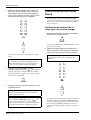
• The 1-2/3-4/5-6/7-8 switches can always be used,
regardless of the on/off status of the LCR switch.
When the 1-2/3-4/5-6/7-8 switches are on, the
post-PAN signal of the monaural input channel
will be sent to the corresponding GROUP bus 1–8.
When the 1-2/3-4/5-6/7-8 switches are on, movements of the PAN control will affect the signal levels sent to GROUP buses 1–8 as shown in the
following diagram.
< Response curve 3 >
1-2/3-4/5-6/7-8 switches= on
Signal level
• LCR switch
When this switch is on, the indicator above the switch
will light, and the post-PAN signal of the monaural
input channel will be sent to the STEREO bus and the
MONO/C bus.
Signal sent to STEREO bus L
Signal level
● When a 1-2/3-4/5-6/7-8 switch is on
PAN will adjust the balance of the signal that is sent
from the monaural input channel to the odd-numbered (1/3/5/7) and even-numbered (2/4/6/8) channels of the corresponding GROUP bus (1-2/3-4/5-6/
7-8).
Signal sent to the MONO/C bus
Signal sent to STEREO bus R
L
● When the LCR switch is on
PAN will adjust the pan of the signal that is sent from
the monaural input channel to the STEREO L/R bus
and MONO/C bus.
< Response curve 1 >
LCR switch= on
Signal level
I PRE switches
Signal sent to GROUP buses 1/3/5/7
Signal sent to GROUP buses 2/4/6/8
ODD
C
PAN control
4
M2500—Owner’s Manual
EVEN
Control panel
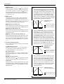
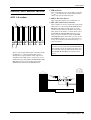
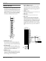
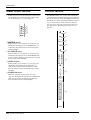
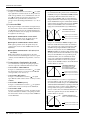
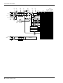
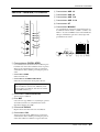
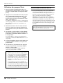
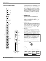
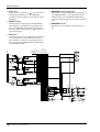
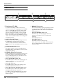
L ON/EDIT switch / ON, CHECK indicators
M PEAK/NOM/SIGNAL indicators
The function of this switch and these indicators will
change depending on the mode of the M2500.
These three indicators allow you to check the prefader signal level of the monaural input channel.
● In normal mode
You can use the ON/EDIT switch to turn the monaural input channel on/off. When the channel is
switched on/off, the ON indicator will be lit/dark to
indicate the status. Channels that are switched off will
not send any signals to the GROUP, STEREO,
MONO/C, or AUX buses, but you can still use the
PFL switch (O) to monitor the signal from the
MONITOR OUT jacks or the PHONES jack.
• PEAK indicator
This will light when the signal exceeds nominal level
by 17 dB.
• NOM (nominal) indicator
This will light when the signal reaches nominal level
(0 dB).
• SIGNAL indicator
This will light when the signal reaches a level 13 dB
below nominal.
● In check mode
When a scene (which contains the on/off state of the
ON/EDIT switches) is selected, the on/off status
memorized in that scene will be indicated by the lit/
dark status of the CHECK indicator. In check mode,
you can also use the ON/EDIT switch to switch the
CHECK indicator between lit/dark. (The current on/
off setting will not be affected.) For details on check
mode, refer to page 32.
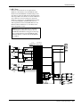
6
M
EQ
Ø
3
1
2
GROUP
AUX
LR
3 5 7
1 3 5 7 9 11 13
4 6 8
2 4 6 8 10 12 14
MONITOR
INPUT
MASTER
(PFL)
PFL AFL
LR
LR
LR
LO
GAIN
g
7
N
PAN
ST
HI
(–26dB)
LO-MID
f
g
(0dB)
f
80
26dB
K
4 stage EQ
HPF
HI-MID
PAD
J
PEAK
NOM
SIGNAL
INSERT I/O
0dB
PHANTOM +48V
MASTER
INPUT
1-24
1-32
1-40
1-48
1-56
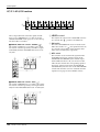
When this switch is on ( ), the pre-fader signal will
be sent to the MONITOR INPUT PFL bus, and can
be monitored from the MONITOR OUT and
PHONES jacks.
MONO
ST
MONO
ST
ON
4
O PFL (pre-fader listen) switch
MONO
ST
ON
5
This adjusts the output level of the monaural input
channel signal. This fader affects the level of the signal that is sent to the GROUP, STEREO, MONO/C,
and AUX (if the PRE switch is off) buses.
STEREO
MONO/C
1
N Channel fader
2
MONO
LCR
L
AUX1
CHECK
ON
AUX2
Control
ON/EDIT
AUX3
from CPU
AUX4
AUX5
PRE
9
AUX6
8
AUX 7-10
Same as AUX 3-6
AUX 11-14
Same as AUX 3-6
PFL
O
M2500—Owner’s Manual
5
Control panel
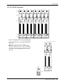
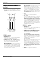
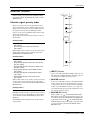
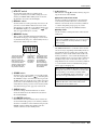
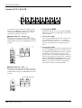
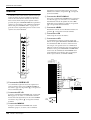
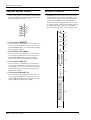
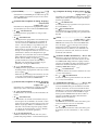
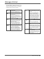
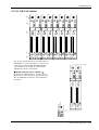
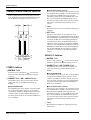
Stereo input channels
The M2500 provides four stereo input channels,
allowing line-level stereo sources such as sub-mixers,
effect processors, and CD players to be input. Of the
stereo input channels 1–4, channel 1 provides both
XLR and RCA phono input jacks, and you can select
and use one of these. Channels 2–4 provide a pair of
TRS phone input jacks. For this reason, there are
slight differences between the controllers of channel 1
and channels 2–4. Our explanation here will be based
on stereo input channel 1, and any differences for stereo input channels 2–4 will be explained later.
GAIN
A
+10
–30
1
B
+10
–20
2
3
A
B
A GAIN A control
This adjusts the input sensitivity of the signal that is
input from the XLR connectors of the ST CH 1
INPUT A jacks (page 26). Levels of +10 dB to –30 dB
are supported. If the A/B select switch (3) is in the B
( ) position, this control will have no effect.
HI
–15
+15
4
LO
B GAIN B control
–15
EQ
0
0
0
This adjusts the input sensitivity of the signal that is
input from the RCA phono connectors of the ST CH
1 INPUT B jacks (page 26). Levels of +10 dB to
–20 dB are supported. If the A/B select switch (3) is
in the A ( ) position, this control will have no
effect.
+15
5
10
AUX1 PRE
C A/B switch
10
AUX2
10
AUX3
0
10
AUX14
0
10
AUX4
BAL
PRE
0
0
6
0
10
AUX5
L
ODD
R
EVEN
1-2
ST
3-4
MONO
8
10
AUX6
9
5-6
10
AUX7
7-8
0
10
AUX8
PRE
0
7
CHECK
ON
10
AUX9
0
10
0
10
0
10
J
5 NOM
AUX12
0
K
AUX13
This is a two-band equalizer. The equalizer type, center frequency, and gain range of each band is shown
below.
10
10
AUX14
–30
D EQ controls
5
10
+10
SIGNAL
PRE
0
GAIN
10 PEAK
AUX11
BAL
Note: Since stereo input channels 2–4 have only
one set of inputs, only one GAIN control is provided. (Nor is there an A/B select switch.) This
control will adjust the input sensitivity of the signal that is input from the TRS phone connectors
for the ST CH 2–4 INPUT jacks (page 26). Levels
of +10 dB to –30 dB are supported.
ON/EDIT
AUX10
0
This selects the input jacks that will be used for stereo
input channel 1. When the switch is in the upward
position ( ), the ST CH 1 INPUT A jacks can be
used. When the switch is in the downward position
( ), the ST CH 1 INPUT B jacks can be used.
20
C
30
L
ODD
R
EVEN
Band
40
L
50
60
M
PFL
HIGH
LOW
6
M2500—Owner’s Manual
Type
Shelving
Center
frequency
10 kHz
100 Hz
Gain
±15 dB
Control panel
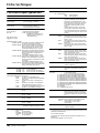
E EQ switch
This turns the equalizer on/off. When the switch is
pressed in ( ), the equalizer is on.
F AUX 1–AUX 14 controls
These adjust the level at which the signal of the stereo
input channel (the L/R input signals mixed to a monaural signal) is sent to the AUX buses 1–14. Placing
the control at the “▲” position will produce nominal
level (0 dB). For AUX buses 1/2, the pre-fader signal
will be output. For AUX buses 3–14, the PRE switch
(7) can be used to switch the signal pre or post
fader.
G PRE switches
If these switches are turned on ( ), the pre-fader
signal will be sent to the corresponding AUX buses. If
these switches are turned off ( ), the post-fader signal will be sent. Switches are provided to independently switch three groups of AUX buses: 3–6, 7–10,
and 11–14.
H BAL control
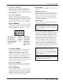
J ON/EDIT switch / ON, CHECK indicators
The function of this switch and these indicators will
change depending on the mode of the M2500.
● In normal mode
You can use the ON/EDIT switch to turn the stereo
input channel on/off. When the channel is switched
on/off, the ON indicator will be lit/dark to indicate
the status. Channels that are switched off will not
send any signals to the GROUP, STEREO. MONO/C,
or AUX buses, but you can still use the PFL switch
(M) to monitor the signal from the MONITOR OUT
jacks or the PHONES jack.
● In check mode
When a scene is selected, the on/off status memorized
in that scene will be indicated by the lit/dark status of
the CHECK indicator. In check mode, you can also
use the ON/EDIT switch to switch the CHECK indicator between lit/dark. For details on check mode,
refer to page 32.
K PEAK/NOM/SIGNAL indicators
This adjusts the level balance of the signal that is sent
to the STEREO or GROUP buses.
These three indicators allow you to check the prefader signal level of the stereo input channel.
● If the ST switch is on
The BAL control will adjust the L/R balance at which
the signal of the stereo input channel is sent to the
STEREO bus.
• PEAK indicator
This will light when the signal mixed to monaural
exceeds nominal level by 17 dB.
● If a 1-2/3-4/5-6/7-8 switch is on
The BAL control will adjust the balance of the stereo
input channel that is sent to the odd-numbered
channels (1/3/5/7) and even-numbered channels (2/
4/6/8) of the corresponding GROUP bus (1-2/3-4/56/7-8). The L ch of the input signal will be sent to the
odd-numbered channel of the group bus, and the R
channel of the input signal will be sent to the evennumbered channel of the group bus.
I Channel assign switches
These switches assign the signal that has passed
through the fader and BAL control to the desired
bus(es). Any or all of the channel assign switches can
be used simultaneously.
• 1-2/3-4/5-6/7-8 switches
When these switches are on ( ), the signal of the
stereo input channel will be sent to the corresponding GROUP bus (1-2/3-4/5-6/7-8).
• NOM (nominal) indicator
This will light when the signal mixed to monaural
reaches nominal level (0 dB).
• SIGNAL indicator
This will light when the signal mixed to monaural
reaches a level 13 dB below nominal.
L Channel fader
This adjusts the output level of the stereo input channel signal. This fader affects the level of the signal that
is sent to the GROUP, STEREO, MONO/C, and AUX
(if the PRE switch is off) buses.
M PFL (pre-fader listen) switch
When this switch is on ( ), the pre-fader signal will
be sent to the MONITOR INPUT PFL bus, and can
be monitored from the MONITOR OUT and
PHONES jacks.
• ST (stereo) switch
When this switch is on ( ), the signal of the stereo
input channel will be sent to the STEREO bus.
• MONO (monaural) switch
When this switch is on ( ), the L and R channels of
the input signal will be mixed to monaural, and sent
to the MONO/C bus. The signal that is sent to the
MONO/C bus is not affected by the BAL control.
M2500—Owner’s Manual
7
Control panel
K
8
9
PEAK
NOM
SIGNAL
A
1
B
2
AUX
GROUP
LR
1 3 5 7 9 11 13
3 5 7
2 4 6 8 10 12 14
4 6 8
L
2 stage EQ
HI
LO
GAIN A
INPUT A
EQ
BAL
R
2 stage EQ
ST CH 1
L
GAIN B
L
INPUT B
ST
MONO
R
AUX1
CHECK
ON
2
AUX2
Control
ON/EDIT
AUX3
from CPU
J
AUX4
AUX5
PRE
7
AUX 7-10
Same as AUX 3-6
AUX 11-14
Same as AUX 3-6
PFL
M
L/MONO
R
8
M2500—Owner’s Manual
2 stage EQ
HI
ST CH 2-4
INPUT
LO
GAIN
2 stage EQ
EQ
ST CH 2-4
Same as ST CH 1
AUX6
6
MONITOR
INPUT
MASTER
(PFL)
PFL AFL
LR
MONO
ST
MONO
ST
ON
5
MONO
ST
ON
4
STEREO
MONO/C
1 3
LR
LR
Control panel
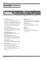
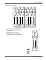
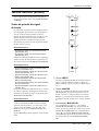
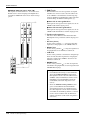
GROUP/AUX master section
AUX 1–6 section
A ON switches
These turn AUX OUT 1–6 on/off. When a switch is
on ( ), the signal of the corresponding AUX bus
will be output to the AUX OUT jack.
B AUX 1–6 master faders
These adjust the output levels of AUX OUT 1–6.
C AFL (after fader listen) switches
1
ON
ON
10
ON
10
ON
10
ON
ON
5
5
5
5
5
5
0
0
0
0
0
0
5
5
5
5
5
5
10
10
10
10
10
10
20
20
20
20
20
20
30
30
30
30
30
30
40
40
40
40
40
40
50
60
50
60
50
60
50
60
50
60
50
60
AFL
AUX1
2
10
AFL
AUX2
AFL
AUX3
AFL
AUX4
AFL
These switches are used to monitor the signal of the
AUX OUT 1–6 section from the MONITOR OUT/
PHONES jacks. When an AFL switch is on (the
switch above the indicator will light), the pre/afterfader signals of the AUX 1–6 section will be sent to
the MONITOR MASTER PFL/AFL buses respectively, and can be monitored via the MONITOR
OUT/PHONES jacks. At this time, you can use the
MASTER PFL switch (page 19) in the monitor section to select whether you will monitor the pre- or
after-fader signal.
AFL
AUX5
AUX6
3
These are the output channels that control the signals
of AUX buses 1–6. The signals that have passed
through these output channels will be output individually from the AUX OUT 1–6 jacks (page 27). In
addition, they pass through the MONITOR MASTER
PFL/AFL buses and can be monitored from the
MONITOR OUT L/R and the PHONES jacks.
Note: If the PFL switch of even one input channel
is turned on, the signal of the MONITOR INPUT
bus will take priority for monitoring. In this case,
be aware that even if the AFL switch is turned on,
the MONITOR MASTER bus cannot be monitored.
MONITOR
INPUT
MASTER
(PFL)
PFL AFL
1
2
3
4
5
AUX
7 9 11 13
8 10 12 14
LR
MONO
ST
MONO
ST
ON
10
MONO
ST
ON
10
LR
LR
6
INSERT I/O
0dB
AUX 1
2
1
to METER
AUX OUT
+4dB
1
ON
AFL
3
AUX 2-6
Same as AUX 1
M2500—Owner’s Manual
9
Control panel
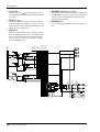
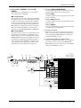
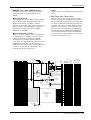
A7/G1–A14/G8 section
1
0
10
0
LEVEL
2
ON
10
LEVEL
ON
AFL
A7 / G1
AFL
A8 / G2
0
10
LEVEL
ON
AFL
A9 / G3
0
10
LEVEL
ON
AFL
A10 / G4
0
10
LEVEL
ON
AFL
A11 / G5
0
10
LEVEL
ON
AFL
A12 / G6
0
10
LEVEL
ON
AFL
A13 / G7
0
10
LEVEL
ON
AFL
A14 / G8
3
These output channels control the signals of AUX
buses 7–14 or GROUP buses 1–8. You can use the
GROUP/AUX FLIP switch (page 14) to select the signals that will be controlled.
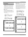
■ GROUP/AUX FLIP switch= GROUP ( )
The signals of AUX buses 7–14 will be sent to channels A7/G1–A14/G8 respectively, and will be output
individually from the AUX/GRP OUT A7/G1–A14/
G8 jacks.
AUX5
0
10
LEVEL
0
AUX6
ON
AFL
A7 / G1
0
0
0
10
LEVEL
10
ON
AFL
A8 / G2
10
AUX7
10
AUX8
PRE
0
10
AUX9
0
10
AUX10
■ GROUP/AUX FLIP switch= AUX ( )
The signals of GROUP buses 1–8 will be sent to channels A7/G1–A14/G8 respectively, and output individually from the AUX/GRP OUT A7/G1–A14/G8 jacks.
0
PAN
ON
L
ODD
R
EVEN
1-2
ST
3-4
MONO
10
AFL
A7 / G1
5-6
7-8
10
LEVEL
0
10
LEVEL
C
LCR
M2500—Owner’s Manual
ON
AFL
A8 / G2
A LEVEL control
This adjusts the output level of AUX/GRP OUT A7/
G1–A14/G8. The “▲” position is nominal level.
B ON switch
This turns AUX/GRP OUT A7/G1–A14/G8 on/off.
When the switch is on ( ), the signals from the A7/
G1–A14/G8 section will be output from the AUX
OUT A7/G1–A14/G8 jacks respectively.
C AFL switch
This switch is used to monitor the signal from the
AUX/GRP OUT A7/G1–A14/G8 section via the
MONITOR OUT/PHONES jacks. If all the input
channel PFL switches are off, you can turn on this
AFL switch to monitor the corresponding signal of
the A7/G1–A14/G8 section from the MONITOR
OUT/PHONES jacks. You can use the MASTER PFL
switch of the monitor section to switch the monitor
signal between pre/post-fader (LEVEL control).
Control panel
G1/A7–G8/A14 section
PAN
4
L
R
MATRIX
5
6
7
PAN
C
ST
PAN
C
L
R
MATRIX
ST
PAN
C
L
R
MATRIX
ST
PAN
C
L
R
MATRIX
ST
PAN
C
L
R
MATRIX
PAN
C
L
ST
R
MATRIX
ST
PAN
C
L
R
MATRIX
C
L
ST
R
MATRIX
ST
MONO
MONO
MONO
MONO
MONO
MONO
MONO
MONO
LCR
LCR
LCR
LCR
LCR
LCR
LCR
LCR
CHECK
ON
CHECK
ON
CHECK
ON
CHECK
ON
CHECK
ON
CHECK
ON
CHECK
ON
CHECK
ON
ON/EDIT
ON/EDIT
ON/EDIT
ON/EDIT
ON/EDIT
ON/EDIT
ON/EDIT
ON/EDIT
10
10
10
10
10
10
10
10
5
5
5
5
5
5
5
5
0
0
0
0
0
0
0
0
5
5
5
5
5
5
5
5
10
10
10
10
10
10
10
10
20
20
20
20
20
20
20
20
30
30
30
30
30
30
30
30
40
40
40
40
40
40
40
40
50
60
50
60
50
60
50
60
50
60
50
60
50
60
50
60
AFL
AFL
AFL
AFL
AFL
AFL
AFL
AFL
8
G1 / A7
G2 / A8
G3 / A9
G4 / A10
G5 / A11
G6 / A12
These are the output channels that control GROUP
buses 1–8 or AUX buses 7–14. Use the GROUP/AUX
FLIP switch (page 14) to select which signals will be
controlled.
G7 / A13
G8 / A14
PAN
L
■ GROUP/AUX FLIP switch= GROUP ( )
The signals of GROUP buses 1–8 will be sent to channels G1/A7–G8/A14 respectively, and will be output
individually from the GRP/AUX OUT G1/A7–G8/
A14 jacks.
R
MATRIX
PAN
C
PAN
C
ST
R
EVEN
1-2
ST
3-4
MONO
L
R
MATRIX
ST
MONO
MONO
LCR
LCR
CHECK
ON
CHECK
ON
ON/EDIT
ON/EDIT
10
10
5
5
0
0
5
5
10
10
20
20
30
30
40
40
50
60
50
60
AFL
L
ODD
C
G1 / A7
AFL
G2 / A8
5-6
7-8
LCR
M2500—Owner’s Manual
11
Control panel
■ GROUP/AUX FLIP switch= AUX ( )
The signals of AUX buses 7–14 will be sent to channels G1/A7–G8/A14 respectively, and will be output
individually from the GRP/AUX OUT G1/A7–G8/
A14 jacks.
PAN
PAN
C
L
R
MATRIX
ST
C
L
R
MATRIX
ST
MONO
MONO
LCR
LCR
CHECK
ON
CHECK
ON
D PAN control
This adjusts the pan of the signal that is sent from the
G1/A7–G8/A14 section to the STEREO or MONO/C
bus. The function of the PAN control will change as
follows, depending on the setting of the channel
assign switch (5).
● When the ST switch is on
PAN will adjust the pan of the signal that is sent from
each channel to the STEREO L/R bus.
● When the LCR switch is on
PAN will adjust the pan of the signal that is sent from
each channel to the STEREO L/R bus and MONO/C
bus.
E Channel assign switches
AUX5
0
ON/EDIT
ON/EDIT
10
10
5
5
0
0
5
5
10
10
20
20
30
30
40
40
50
60
50
60
AFL
10
0
10
AUX7
10
AUX8
PRE
0
0
10
AUX9
10
AUX10
12
• ST (stereo) switch
If this switch is on ( ), the post-PAN signal of the
output channel will be sent to the STEREO bus.
• MONO (monaural) switch
If this switch is on ( ), the signal of the output
channel will be sent to the MONO/C bus.
AFL
AUX6
G1 / A7
0
M2500—Owner’s Manual
These switches assign the post-fader post-PAN signal
to the desired bus.
G2 / A8
• LCR switch
If this switch is on, the indicator above the switch will
light, and the post-PAN signal of the output channel
will be sent to the STEREO bus and the MONO/C
bus.
• MATRIX switch
IF this switch is on ( ), the signal of the output
channel will be sent to the corresponding MATRIX
bus.
Note:
• The LCR switch takes priority over the ST/
MONO switch. If the LCR switch is on, the
post-PAN signal of the G1/A7–G8/A14 section
will be sent to the STEREO bus (L/R) and
MONO/C bus regardless of the on/off status of
the ST/MONO switch. (Refer to response curve
diagram 1 on page 4.)
• If the LCR switch is off, the ST/MONO switch
will function as a conventional channel assign
switch. If ST is on, the post-PAN signal of the
G1/A7–G8/A14 section will be sent to the ST
bus. If the MONO switch is on, the signal of
the G1/A7–G8/A14 section will be sent directly
to the MONO/C bus. (Refer to response curve
diagram 2 on page 4.)
Control panel
F ON/EDIT switch / ON, CHECK indicators
G Fader
The function of this switch and these indicators will
change depending on the mode of the M2500.
This adjusts the output level of the GRP/AUX OUT.
H AFL (after fader listen) switch
● In normal mode
You can use the ON/EDIT switch to turn each G1/
A7–G8/A14 channel on/off. When the channel is
switched on/off, the ON indicator will be lit/dark to
indicate the status. Channels that are switched off will
not send any signals to the STEREO, MONO/C, or
MATRIX buses.
7
MATRIX
to METER
GRP/AUX OUT
+4dB
G1/A7
PAN
6
LR
LR
LR
LR
LR
ST
4
CHECK
ON
LR
MONITOR
INPUT
MASTER
(PFL)
PFL AFL
MONO
ST
MONO
ST
ON
INSERT I/O
0dB
G1/A7
MONO
ST
ON
GROUP
AUX
3 5 7
1 3 5 7 9 11 13
4 6 8
2 4 6 8 10 12 14
SUB IN
2
G1/A7
G2/A8
G3/A9
G4/A10
G5/A11
G6/A12
G7/A13
G8/A14
1
STEREO
MONO/C
● In check mode
When a scene (which contains the on/off state of the
ON/EDIT switches) is selected, the on/off status
memorized in that scene will be indicated by the lit/
dark status of the CHECK indicator. In check mode,
you can also use the ON/EDIT switch to switch the
CHECK indicator between lit/dark. (The current on/
off setting will not be affected.) For details on check
mode, refer to page 32.
STEREO
MONO/C
This switch allows you to monitor the signal of the
G1/A7–G8/A14 section from the MONITOR OUT/
PHONES jacks. If the input channel PFL switches are
all off, turning this AFL switch on (the indicator
above the switch will light) will allow you to monitor
the corresponding G1/A7–G8/A14 section signal
from the MONITOR OUT/PHONES jacks. The
monitor signal can be switched between pre/postfader using the MASTER PFL switch of the monitor
section.
MONO
LCR
MATRIX
Control
5
ON/EDIT
from CPU
AFL
8
to METER
LEVEL
ON
1
2
AUX/GRP OUT
+4dB
A7/G1
AFL
3
GRP/AUX G2/A8-G8/A14
and
AUX/GRP A8/G2-A14/G8
Same as
G1/A7
and
G7/A1
GROUP
AUX
GROUP/AUX FLIP
M2500—Owner’s Manual
13
Control panel
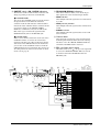
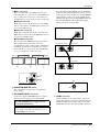
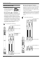
● When AUX ( ) is selected
The signals of GROUP buses 1–8 will be routed
through the A7/G1–A14/G8 section and sent to the
AUX/GRP OUT jacks. The signals of AUX buses 7–14
will be routed through the G1/A7–G8/A14 section,
and sent to the GROUP/AUX OUT jacks, the STEREO bus, MONO/C, and MATRIX buses.
This setting is more convenient when you are using
the M2500 as a “monitor console” to control individual monitor levels on stage, since you will be able to
use the 100 mm faders to control each of the AUX
buses (1–14).
GROUP/AUX FLIP switch
The M2500 provides a GROUP/
AUX FLIP switch that
exchanges the output destinations of GROUP buses 1–8 and
AUX buses 7–14.
GROUP
AUX
GROUP/AUX FLIP
● When GROUP ( ) is selected
The signals of GROUP buses 1–8 will be routed
through the G1/A7–G8/A14 section, and sent to the
GROUP/AUX OUT jacks, the STEREO bus, MONO/C,
and MATRIX buses. The signals of AUX buses 7–14 will
be routed through the A7/G1–A14/G8 section, and sent
to the AUX GRP OUT jacks. With this setting, AUX
buses 7–14 can be used as conventional AUX buses, and
GROUP buses 1–8 can be used as group buses. This setting is more convenient when you are using the M2500
as a main console, since you will be able to use the 100
mm faders to control the group buses.
GROUP
AUX
GROUP
AUX
When AUX is selected
PAN
PAN
C
L
R
MATRIX
When GROUP is selected
ST
C
L
R
MATRIX
GRP/AUX OUT jacks
STEREO bus
MONO/C bus
MATRIX bus
ST
MONO
MONO
LCR
LCR
CHECK
ON
CHECK
ON
AUX/GRP OUT jacks
AUX5
0
10
0
LEVEL
0
ON
AFL
A7 / G1
0
0
10
LEVEL
ON/EDIT
ON/EDIT
10
10
5
5
0
0
5
5
10
10
20
20
30
30
40
40
50
60
50
60
10
AUX6
ON
AFL
A8 / G2
A7/G1–A14/G8 section
10
AUX7
10
AUX8
PRE
0
10
AUX9
PAN
0
PAN
C
C
10
AUX10
L
R
L
R
GRP/AUX OUT jacks
STEREO bus
MONO/C bus
MATRIX bus
AUX5
MATRIX
ST
MATRIX
ST
MONO
MONO
LCR
LCR
0
G1 / A7
0
Input
channel
CHECK
ON
0
CHECK
ON
ON/EDIT
10
10
5
5
0
0
5
5
10
10
L
ODD
R
EVEN
1-2
ST
3-4
MONO
20
20
30
30
40
40
50
60
50
60
10
10
AUX9
0
10
AUX10
AUX/GRP OUT jacks
Input
channel
PAN
L
ODD
5-6
7-8
14
LCR
G1 / A7
G2 / A8
M2500—Owner’s Manual
R
EVEN
ST
3-4
MONO
5-6
AFL
G1/A7–G8/A14 section
10
LEVEL
0
10
LEVEL
C
1-2
7-8
AFL
G1/A7–G8/A14 section
AUX8
ON
C
G2 / A8
10
AUX7
0
PAN
AFL
PRE
0
ON/EDIT
AFL
10
AUX6
LCR
AFL
A7 / G1
ON
AFL
A8 / G2
A7/G1–A14/G8 section
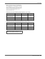
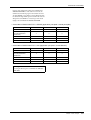
Control panel
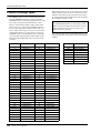
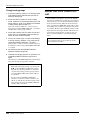
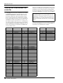
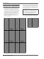
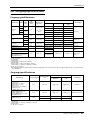
When you change the setting of the GROUP/AUX
FLIP switch, numerous functions of the output channels of GROUP buses 1–8 and AUX buses 7–14 will
change in addition to the faders. The functions available for the output channels of each bus are shown
below for each setting (GROUP/AUX) of the
GROUP/AUX FLIP switch.
• GROUP/AUX FLIP switch= GROUP (principal application: main console)
Output channel
GROUP buses 1–8
AUX buses 1–6
AUX buses 7–14
Master control
100 mm faders
100 mm faders
Rotary faders
❍
✕
✕
Channel assign switch
(MATRIX/ST/MONO/LCR)
PAN control
❍
✕
✕
Mute switch
ON/EDIT
ON
ON
INSERT I/O
❍
❍
✕
• GROUP/AUX FLIP switch= AUX (principal application: monitor console)
Output channel
GROUP buses 1–8
AUX buses 1–6
AUX buses 7–14
Master control
Rotary faders
100 mm faders
100 mm faders
✕
✕
❍
Channel assign switch
(MATRIX/ST/MONO/LCR)
PAN control
✕
✕
❍
Mute switch
ON
ON
ON/EDIT
INSERT I/O
✕
❍
❍
Note: The output channels of AUX buses 1–6 are
not affected by the GROUP/AUX FLIP switch.
M2500—Owner’s Manual
15
Control panel
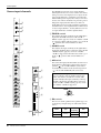
Stereo/monaural master
section
This section controls the signals that are output from
the rear panel ST OUT L/R and MONO/C OUT jacks
(page 28).
1
MATRIX
5
MATRIX
● In check mode
When a scene (which contains the on/off state of the
ON/EDIT switches) is selected, the on/off status
memorized in that scene will be indicated by the lit/
dark status of the CHECK indicator. In check mode,
you can also use the ON/EDIT switch to switch the
CHECK indicator between lit/dark. (The current on/
off setting will not be affected.) For details on check
mode, refer to page 32.
C Fader
This adjusts the ST OUT L/R output level.
D AFL switch
CHECK
ON
2
3
CHECK
ON
ON/EDIT
ON/EDIT
10
10
5
5
0
0
5
5
10
10
20
20
30
30
40
40
50
60
50
60
6
MONO/C section
E MATRIX switch
AFL
AFL
STEREO
MONO/C
4
8
7
STEREO section
A MATRIX switch
If this switch is on ( ), the post-fader ST OUT L/R
signal will be sent to the matrix (page 18).
B ON/EDIT switch / ON, CHECK indicators
The function of this switch and these indicators will
change depending on the mode of the M2500.
● In normal mode
You can use the ON/EDIT switch to turn ST OUT L/
R on/off. When this is switched on/off, the ON indicator will be lit/dark to indicate the status. Channels
that are switched off will not send any signals to the
ST OUT L/R jacks or to the matrix.
16
M2500—Owner’s Manual
Using this switch, the signal sent to the ST OUT L/R
jacks can be monitored from the MONITOR OUT/
PHONES jacks. If the PFL switches of all input channels are off, turning this AFL switch on (the indicator
above the switch will light) will allow you to monitor
the output signal of the STEREO section from the
MONITOR OUT/PHONES jacks. Use the MASTER
PFL switch of the monitor section to switch the monitor signal between pre/post-fader.
If this switch is on ( ), the post-fader MONO/C signal will be sent to the matrix (page 18).
F ON/EDIT switch / ON, CHECK indicators
The function of this switch and these indicators will
change depending on the mode of the M2500.
● In normal mode
You can use the ON/EDIT switch to turn MONO/C
OUT on/off. When this is switched on/off, the ON
indicator will be lit/dark to indicate the status. Channels that are switched off will not send any signals to
the MONO/C jack or to the matrix.
● In check mode
When a scene (which contains the on/off state of the
ON/EDIT switches) is selected, the on/off status
memorized in that scene will be indicated by the lit/
dark status of the CHECK indicator. In check mode,
you can also use the ON/EDIT switch to switch the
CHECK indicator between lit/dark. (The current on/
off setting will not be affected.) For details on check
mode, refer to page 32.
G Fader
This adjusts the output level of MONO/C.
Control panel
H AFL switch
Using this switch, the signal sent to the MONO/C
OUT jack can be monitored from the MONITOR
OUT/PHONES jacks. If the PFL switches of all input
channels are off, turning this AFL switch on (the
indicator above the switch will light) will allow you to
monitor the output signal of the MONO/C section
from the MONITOR OUT/PHONES jacks. Use the
MASTER PFL switch of the monitor section to switch
the monitor signal between pre/post-fader.
INSERT I/O
0dB
ST L
LR
SUB IN
LR
LR
MONO
ST
MONO
ST
ON
LR
MONITOR
INPUT
MASTER
(PFL)
PFL AFL
MONO
ST
ON
G1/A7
G2/A8
G3/A9
G4/A10
G5/A11
G6/A12
G7/A13
G8/A14
STEREO
MONO/C
MATRIX
STEREO
MONO/C
Note: When using the AFL switch to monitor the
signal of the MONO/C section from the MONITOR OUT jacks, be aware that the monitor signal
will not be output from the MONITOR OUT
MONO/C jack, but will be output monaurally
from the MONITOR OUT L/R jacks.
LR
LR
3
ST OUT
+4dB
L
CHECK
ON
1
Control
ON/EDIT
from CPU
2
AFL
4
MATRIX
INSERT I/O
0dB
ST R
ST OUT
+4dB
R
ON
INSERT I/O
0dB
MONO/C
7 6
+4dB
MONO/C
CHECK
ON
5
MATRIX
Control
ON/EDIT
from CPU
AFL
8
L
L+R
MONITOR
OUT
+4dB
LEVEL
R
MASTER
PFL
MONO/C
ON
INPUT
MASTER
PHONES
M2500—Owner’s Manual
17
Control panel
D G1/A7–G8/A14 controls
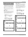
Matrix section
The M2500 provides an eight channel matrix section
that allows the output signals from the G1/A7–G8/
A14 section, the output signals from the stereo/monaural master section, and the input signals from the
SUB IN MATRIX jacks to be mixed at a desired level.
Matrix 1–8 are output individually from MATRIX
OUT jacks 1–8 (page 27), and can be used as mixes
for foldback or individual monitor systems.
When the MATRIX switches of the G1/A7–G8/A14
section (page 11) are on, these controls adjust the
level of the signal that is sent from the corresponding
GRP/AUX OUT to the matrix. The “▲” position is
nominal level.
E LEVEL control
This adjusts the final output level of the matrix. The
“▲” position is nominal level.
F ON switch
This switches the output of the matrix on/off.
G AFL switch
0
0
1
0
L
SUB IN
L
ST
R
2
0
R
3
0
MONO/C
0
G1 / A7
Using this switch, the signal of the matrix can be
monitored from the MONITOR OUT/PHONES
jacks. If the PFL switches of all input channels are off,
turning this AFL switch on will allow you to monitor
the output signal of the corresponding matrix from
the MONITOR OUT/PHONES jacks. Use the MASTER PFL switch of the monitor section to switch the
monitor signal between pre/post-fader (LEVEL control).
0
G2 / A8
0
4
G1/A7
G2/A8
G3/A9
G4/A10
G5/A11
G6/A12
G7/A13
G8/A14
G4 / A10
0
LR
SUB IN
MATRIX
0
STEREO
MONO/C
G3 / A9
LR
4
G5 / A11
G1/A7
0
G6 / A12
G2/A8
0
G7 / A13
G7/A9
0
G8 / A14
6
ON
5
7
G7/A11
G7/A12
AFL
G7/A13
MATRIX 1
G8/A14
ST L
5
LEVEL
6
to METER
MATRIX OUT
+4dB
1-8
ON
MONITOR
INPUT
MASTER
(PFL)
PFL AFL
2
ST R
A SUB IN L/R control
MONO/C
These adjust the signal levels that are input to the
matrix from the rear panel SUB IN MATRIX jacks
(page 28). The “▲” position is nominal level (0 dB).
SUB IN L
SUB IN R
1
B ST L/R controls
When the MATRIX switch of the STEREO section
(page 16) is on, these controls adjust the level of the
signal that is sent from the STEREO section to the
matrix. The “▲” position is nominal level.
C MONO/C control
When the MATRIX switch of the MONO/C section
(page 16) is on, this control adjusts the level of the
signal that is sent from the MONO/C section to the
matrix. The “▲” position is nominal level.
18
M2500—Owner’s Manual
L
SUB IN
+4dB
MATRIX
R
3
LR
AFL
7
MONO
ST
MONO
ST
ON
10
LEVEL
MONO
ST
ON
0
G7/A10
LR
LR
Control panel
Monitor section
In this section you can select the signal that will be
monitored from the MONITOR OUT jacks and the
PHONES jacks.
1
INPUT
MASTER
MASTER
PFL
Monitor signal priority order
4
L+R
There is a priority order for the signals that can be
selected as monitor sources. While a higher priority
signal is being monitored, it is not possible to monitor signals of a lower priority. Multiple monitor
sources can be selected simultaneously if they are all
of the same priority level.
The priority order of the various monitor sources is
shown below.
0
2
3
10
5
LEVEL
6
ON
MONITOR
Priority order 1
0
10
7
PHONES
• Pre-fader signal of a monaural input channel
(PFL switch)
• Pre-fader signal of a stereo input channel
(PFL switch)
When a PFL switch is turned on, the pre-fader signal
of that input channel can be monitored from the
MONITOR OUT/PHONES jacks.
Priority order 2
• Pre/post-fader signals of the AUX 1–6 section
(AFL switch)
• Pre/post-fader signals of the A7/G1–A14/G8 section (AFL switch)
• Pre/post-fader signals of the G1/A7–G8/A14 section (AFL switch)
• Pre/post-fader signals of the STEREO section
(AFL switch)
• Pre/post-fader signals of the MONO/C section
(AFL switch)
• Pre/post-fader signals of the matrix section
(AFL switch)
When a AFL switch of one of these sections is turned
on, the pre/post-fader signal of the corresponding
section can be monitored from the MONITOR OUT/
PHONES jacks.
Priority order 3
• ST OUT (L, R, MONO/C) output signals
If all PFL and AFL switches of priority orders 1 and 2
are off, the ST OUT (L, R, MONO/C) output signal
can be monitored from MONITOR OUT L, R, and
MONO/C.
The PHONES jack will monitor the ST OUT (L/R)
output signal.
8
PHONES
A INPUT indicator
If even one of the input channel PFL switches are on,
this indicator will light. When this indicator is lit, you
are monitoring a signal of priority order 1.
B MASTER indicator
If even one of the AFL switches of the GROUP/AUX
master section, the stereo/monaural master section,
or the matrix section are on, this indicator will light.
In this case if the INPUT indicator (1) is dark, you
are monitoring the pre/post-fader signal from one of
the sections (priority order 2).
C MASTER PFL switch
If this switch is on ( ), the MONITOR MASTER
PFL signals (pre-fader signals of priority order 2) can
be monitored from the MONITOR OUT/PHONES
jacks. If this switch is off ( ), the MONITOR MASTER AFL signals (after-fader signals of priority order
2) can be monitored from the MONITOR OUT/
PHONES jacks.
M2500—Owner’s Manual
19
Control panel
D L+R switch
G PHONES (headphone) control
If this switch is on ( ), the monitor signal sent to
the MONITOR OUT/PHONES jacks will be mixed to
monaural.
This adjusts the level of the signal that is output from
the PHONES jack. It does not affect the signal that is
output from the MONITOR OUT jacks. The “▲”
position is nominal level.
E LEVEL control
H PHONES jack
This adjusts the final output level from the MONITOR OUT jacks (L, R, MONO/C). It does not affect
the signal that is output from the PHONES jack. The
“▲” position is nominal level.
A set of monitoring headphones can be connected
here.
F ON switch
LR
SUB IN
LR
LR
MONO
ST
MONO
ST
ON
LR
MONITOR
INPUT
MASTER
(PFL)
PFL AFL
MONO
ST
ON
G1/A7
G2/A8
G3/A9
G4/A10
G5/A11
G6/A12
G7/A13
G8/A14
STEREO
MONO/C
MATRIX
STEREO
MONO/C
This is an on/off switch for the signal that is output
from the MONITOR OUT jacks (L, R, MONO/C). If
this is on, the indicator above the switch will light.
This switch does not affect the signal that is output
from the PHONES jack.
LR
LR
INSERT I/O
0dB
ST L
ST OUT
+4dB
L
CHECK
ON
Control
ON/EDIT
from CPU
AFL
MATRIX
INSERT I/O
0dB
ST R
ST OUT
+4dB
R
ON
INSERT I/O
0dB
MONO/C
+4dB
MONO/C
CHECK
ON
MATRIX
Control
ON/EDIT
from CPU
AFL
4
5
L+R
LEVEL
6
L
MONITOR
OUT
+4dB
R
MASTER
PFL
MONO/C
ON
INPUT
MASTER
PHONES
1 2
20
M2500—Owner’s Manual
7
8
Control panel
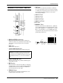
Talkback/oscillator section
F AUX 1-2 switch
G AUX 3-6 switch
H AUX 7-10 switch
I AUX 11-14 switch
J ST switch
PINK
K MONO/C switch
10kHz
1kHz
100Hz
2
AUX1-2
ON
OSCILLATOR
AUX3-6
AUX7-10
AUX11-14
6
7
8
9
These switches send the talkback or oscillator signal
to AUX buses 1–2, AUX buses 3–6, AUX buses 7–10,
AUX buses 11–14, the STEREO bus, and/or the
MONO/C bus. Each switch can be turned on/off
independently.
3
ST
MIC
4
MONO/C
0
1
J
K
10
3
4
5
AUX
7 9 11 13
8 10 12 14
LR
6
from CPU
TB/OSC
5
2
STEREO
MONO/C
1
MIC
ON
TALKBACK
ON
3
TB/OSC
5 4
67 8 9 JK
A OSCILLATOR select switches
These switches select a test tone oscillator, and start
oscillation. Only one switch at a time can be selected.
The corresponding indicator will light to show the
switch that is turned on.
• PINK switch
This generates pink noise.
• 10 kHz/1 kHz/100 Hz switches
These generate a sine wave of the corresponding frequency.
Note: The oscillator cannot be used together with
talkback. If you wish to use the oscillator, you must
turn off the talkback ON switch (5).
B OSCILLATOR ON switch
This switch turns the oscillator on/off.
C MIC jack
This is an XLR-3-31 input jack (unbalanced) for connecting a talkback mic. Mics of 50–600Ω impedance
are supported.
D TB/OSC control
This adjusts the level of the talkback or oscillator.
E ON switch
This is an on/off switch for the talkback. If this is on,
the indicator above the switch will light. If you wish
to use the oscillator, you must turn off this switch.
M2500—Owner’s Manual
21
Control panel
Meter select section
In this section you can select the source whose level
will be displayed by the meter bridge section. Only
one of the sources 1–4 can be selected.
MATRIX
A7-14/G1-8
AUX1-6
G1-8/A7-14
1
2
3
4
Control section
The M2500 is able to save “scenes“ that contain the
on/off status for each monaural/stereo input channel,
the G1/A7–G8/A14 section, the STEREO section, and
the MONO/C section. (This functionality is referred
to as “scene memory.”) In the Control section you
can save scenes, and recall a previously-saved scene.
(For details on scene memory procedure, refer to
page 30.)
UTILITY
1
RECALL
2
METER
SELECT
3
A MATRIX switch
MEMORY
If this switch is pressed, meters 1/7–8/14 (page 24)
will display the output levels of MATRIX OUT 1–8.
At this time, the indicator located at the left of the
switch will light.
C AUX 1-6 switch
If this switch is pressed, meters 1/7–6/12 (page 24)
will display the output levels of AUX OUT 1–6.
(Meters 7/13 and 8/14 will not function.) At this
time, the indicator located at the left of the switch
will light.
5
CHECK
B A7-14/G1-8 switch
If this switch is pressed, meters 1/7–8/14 (page 24)
will display the output levels of AUX/GROUP OUT
A7/G1–A14/G8. At this time, the indicator located at
the left of the switch will light.
4
STORE
1
2
3
4
5
6
7
8
9
6
0
ENTER
7
D G1-8/A7-14 switch
When this switch is pressed, meters 1/7–8/14
(page 24) will display the output levels of GRP/AUX
OUT G1/A7–G8/A14. At this time, the indicator
located at the left of the switch will light.
SCENE
MEMORY
1
2
3
4
5
6
7
8
DIRECT
RECALL
CONTROL
22
M2500—Owner’s Manual
8
Control panel
G ▲/▼ switches
A UTILITY switch
Pressing this switch will access Utility mode
(page 34), in which you can make settings for scene
memory and MIDI. When Utility mode is selected,
the indicator above the switch will light.
B RECALL switch
Use this switch to recall a previously-stored scene. If
you select a scene number that has not been stored
and attempt to recall it, the scene will not change, but
the MEMORY display (3) will indicate “
” (No
data) for approximately two seconds.
C MEMORY display
This is a three-digit LED display. In Normal mode
and Check mode (page 32), it displays a scene memory number in the range of 1–130. In Utility mode, it
indicates the utility item or its value.
The function of the ▲/▼ switches will vary depending on the mode of the M2500.
● Normal mode/Check mode
Use these switches to increment or decrement the
scene memory number. However, scene memory
numbers 129 and 130, and scene memory numbers
1–8 when using mute groups (page 37) can be
selected only by using the 0–9/ENTER switches.
● Utility mode
Use the switches to change the value of the selected
utility item.
Hint: In Normal mode and Check mode, holding
either of the ▲/▼ switches for one second or more
will cause the scene memory number to change
more rapidly.
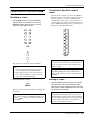
H DIRECT RECALL 1–8 switches
This will light if the display shows a scene
memory number in
which no scene has
been stored. If not even
one scene has been
stored in scene memory,
this dot will light when
the power is turned on.
This will light
while bulk
data is being
received at
the MIDI IN
connector.
This will light when
the settings of the
last-recalled scene
are modified in
Normal mode, or
when the settings
of the scene selected in Check mode
are modified.
D STORE switch
Use this to store a scene. When you press this switch
once, the display will indicate “
,” indicating that
the M2500 is ready to store the scene. If you press the
STORE switch once again, the scene will be stored. If
you decide to cancel without storing, press any other
switch. Before storing a scene in scene memory, make
sure that memory protect (page 34) is turned off.
The DIRECT RECALL 1–8 switches can be used in
one of two ways, depending on the Utility mode setting. With the factory settings, these switches will
function as “direct recall” switches that recall scene
memory numbers 1–8 at a touch. By changing the
setting in Utility mode, you can use these switches to
simultaneously select or cancel the mute (off) settings that have been saved in scene memory numbers
1–8. (For details on direct recall and mute groups,
refer to page 31 and page 37.)
Note: Pressing a DIRECT RECALL switch will not
change the scene if no scene has been saved in the
corresponding scene memory number. If this
occurs, the MEMORY display will indicate “
”
(No data) for approximately two seconds.
Note: Be aware that in Check mode, pressing a
DIRECT RECALL switch will forcibly cancel
Check mode and recall the scene.
E CHECK switch
Use this to change from Normal mode to Check
mode. In Check mode, the indicator located above
the switch will light.
F 0–9/ENTER switches
In Normal mode or Check mode, these switches are
used to numerically specify a scene memory number.
Use the 0–9 switches to enter a number, and press the
ENTER switch to finalize that number. The 0–9
switches cannot be used in Utility mode.
M2500—Owner’s Manual
23
Control panel
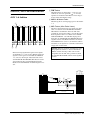
Meter bridge
1
20
5 3 1
0
10 7
VU
1/7
PEAK
20
3
+
5 3 1
0
10 7
VU
PEAK
20
3
10 7
+
3 10
4
2
PEAK
VU
20
3
+
2/8
5 3 1
0
10 7
VU
PEAK
20
3
+
7/13
5 3 1
0
10 7
VU
PEAK
3
+
+15V
–15V
+12V
PHANTOM MASTER
8/14
20
5 3 1
0
10 7
PEAK
VU
20
3
+
STEREO L
5 3 1
0
10 7
VU
MONO/C
PFL/AFL L
3
A 1/7–8/14 level meters
According to the setting of the meter select switches
(page 22), these indicate the output levels of
MATRIX OUT 1–8, AUX/GRP OUT A7/G1–A14/G8,
AUX OUT 1–6, or GRP/AUX OUT G1/A7–G8/A14.
(If the AUX 1–6 switch has been selected in the meter
select section, meters 7/13 and 8/14 will not function.) Each meter has a PEAK indicator that lights
3 dB before peak level.
B +15V/–15V/+12V indicators
The respective indicator will light when +15V/–15V/
+12V power is being supplied correctly from the rear
panel DC POWER INPUT connector (page 29) to
the M2500 mixer.
C PHANTOM MASTER indicator
This will light when the rear panel PHANTOM MASTER switch (page 29) is on.
D STEREO, PFL/AFL level meters
The signal shown by each level meter will change
depending on the settings of the input channel PFL
switches and the AFL switches of the GROUP/AUX
master section etc.
• PFL/AFL switches= all off
The meters will show the output level of the signals
that are output from the ST OUT L/R jacks (page 28).
• PFL switch= on
The meters will show the signal level that is output
from the MONITOR INPUT PFL bus.
• AFL switch= on (PFL switches= all off)
The meters will show the signal level that is output
from the MONITOR MASTER AFL bus.
Each meter has a PEAK indicator that lights 3 dB
before peak level.
24
M2500—Owner’s Manual
PEAK
20
3
+
–
5 3 1
0
10 7
PEAK
3
VU
+
STEREO R
PFL/AFL R
5
E MONO/C level meter
The signal shown by this level meter will change
depending on the settings of the input channel PFL
switches and the AFL switches of the GROUP/AUX
master section etc.
• PFL/AFL switches= all off
The meter will show the output level of the signal
that is output from the MONO/C OUT jack
(page 28).
• PFL switch= on
• AFL switch= on
The MONO/C level meter will not function.
This meter has a PEAK indicator that lights 3 dB
before peak level.
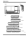
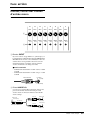
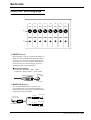
Rear panel
Monaural input channel
input/output jacks
24
23
22
21
20
19
18
17
INPUT
INPUT
INPUT
INPUT
INPUT
INPUT
INPUT
INPUT
INSERT
I/O 0dB
INSERT
I/O 0dB
INSERT
I/O 0dB
INSERT
I/O 0dB
INSERT
I/O 0dB
INSERT
I/O 0dB
INSERT
I/O 0dB
INSERT
I/O 0dB
1
2
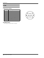
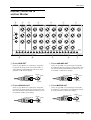
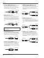
A INPUT jacks
These are XLR-3-31 type input jacks (balanced). If
the rear panel PHANTOM MASTER switch and the
+48 V switch of the corresponding monaural input
channel are on, phantom power will be supplied. The
nominal input levels and pin wiring are as follows.
■ Nominal input
• –26 dB pad switch= on / +10 dB to –34 dB
• –26 dB pad switch= off / –16 dB to –60 dB
Male XLR plug
1 (ground)
3 (cold)
2 (hot)
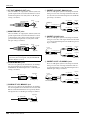
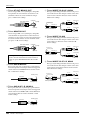
B INSERT I/O jacks
These are TRS phone jacks for inserting external
effect units into each monaural input channel. The
nominal level is 0 dB. The pin wiring is as follows.
Tip (send)
1/4" phone plug
Tip (send)
Ring (return)
1/4" TRS phone plug
Sleeve (ground)
To processor’s input
Sleeve (ground)
Tip (return)
1/4" phone plug
Connect to INSERT I/O jack
From processor’s output
Sleeve (ground)
M2500—Owner’s Manual
25
Rear panel
Stereo input channel input/
output jacks
ST CH 4 ST CH 3 ST CH 2
INPUT
INPUT
INPUT
L/MONO
L/MONO
L/MONO
R
R
R
ST CH 1
INPUT A
L
5
3
R
PHANTOM
MASTER
OFF
ON
INPUT B
L
R
READ OWNER’S MANUAL
C INPUT A jacks
4
DC POWER INPUT
E INPUT jacks
These are XLR-3-31 type input jacks (balanced) for
stereo input channel 1. Nominal input level is +10 dB
to –30 dB. In order to use these jacks, you must set
the A/B select switch of stereo input channel 1 to the
A position. The pin wiring is as follows.
Male XLR plug
1 (ground)
3 (cold)
These are TRS phone input jacks (balanced) for stereo input channels 2–4. Nominal input level is
+10 dB to –30 dB. The pin wiring is as follows.
Hot
Cold
Ground
2 (hot)
D INPUT B jacks
These are RCA phono input jacks (unbalanced) for
stereo input channel 1. Nominal input level is +10 dB
to –20 dB. In order to use these jacks, you must set
the A/B select switch of stereo input channel 1 to the
B position. The pin wiring is as follows.
RCA phono plug
Tip (send)
Sleeve (ground)
26
M2500—Owner’s Manual
If you wish to input a monaural signal to stereo input
channels 2–4, insert a plug only into the L/MONO
jack. In this case, the signal that is input to the L/
MONO jack will be sent to both L and R of the stereo
input channel.
Rear panel
Master section input/output
jacks
L
MIDI
6
5
MONITOR
OUT +4dB
4
ST OUT
3
MATRIX OUT +4dB
+4dB
2
AUX/GRP OUT +4dB
1
GRP/AUX OUT +4dB
AUX OUT +4dB
L
L
5
1
A11/
G6
A7/
G1
G5/
A11
G1/
A7
3
1
MONO
/C
MONO
/C
6
2
A12/
G6
A8/
G2
G6/
A12
G2/
A8
4
2
R
R
7
3
A13/
G7
A9/
G3
G7/
A13
G3/
A9
5
8
4
A14/
G8
A10/
G4
G8/
A14
G4/
A10
6
IN
OUT
THRU
ST R
MONO/C
ST L
6
5
4 AUX 3
2
1
G8/A14
INSERT I/O
K
G7/A13
G5/A11
G4/A10
G3/A9
G2/A8
G1/A7
ST R
MONO/C
9
A AUX OUT jacks
ST L
8
L
MATRIX
+4dB
7
C AUX/GRP OUT jacks
These are XLR-3-32 output jacks (balanced) that
individually output the signals of each channel of the
AUX 1–6 section. Nominal output level is +4 dB. The
pin wiring is as follows.
2 (hot)
3 (cold)
These are XLR-3-32 output jacks (balanced) that
individually output the signals of each channel of the
A7/G1–A14/G8 section. Nominal output level is
+4 dB. The pin wiring is as follows.
Female XLR plug
2 (hot)
3 (cold)
1 (ground)
1 (ground)
D MATRIX OUT jacks
B GRP/AUX OUT jacks
These are XLR-3-32 output jacks (balanced) that
individually output the signals of each channel of the
G1/A7–G8/A14 section. Nominal output level is
+4 dB. The pin wiring is as follows.
These are XLR-3-32 output jacks (balanced) that
individually output the matrix 1–8 signals. Nominal
output level is +4 dB. The pin wiring is as follows.
Female XLR plug
Female XLR plug
R
SUB IN
+4dB
J
Female XLR plug
G6/A12
2 (hot)
2 (hot)
3 (cold)
3 (cold)
1 (ground)
1 (ground)
M2500—Owner’s Manual
27
Rear panel
E ST OUT, MONO/C OUT jacks
I INSERT I/O G1/A7–G8/A14 jacks
These are XLR-3-32 output jacks (balanced) that output the signal of the stereo/monaural master section.
Nominal output level of each jack is +4 dB. The pin
wiring is as follows.
These are TRS phone jacks for inserting an external
effect processor into each output channel of the G1/
A7–G8/A14 section. Nominal input level is 0 dB. The
pin wiring is as follows.
Tip (send)
2 (hot)
Female XLR plug
3 (cold)
1/4" phone plug
Tip (send)
Ring (return)
1/4" TRS phone plug
1 (ground)
To processor’s input
Sleeve (ground)
Tip (return)
Sleeve (ground)
1/4" phone plug
Connect to INSERT I/O jack
From processor’s output
F MONITOR OUT jacks
Sleeve (ground)
These are XLR-3-32 output jacks (balanced) that output the signal of the stereo/monaural master section,
or the monitor source that is selected by the control
panel. Nominal output level of each jack is +4 dB.
The pin wiring is as follows.
J INSERT I/O AUX jacks
These are TRS phone jacks for inserting an external
effect processor into each output channel of the AUX
1–6 section. Nominal input level is 0 dB. The pin wiring is as follows.
2 (hot)
Female XLR plug
3 (cold)
Tip (send)
1/4" phone plug
Tip (send)
Ring (return)
1 (ground)
1/4" TRS phone plug
Sleeve (ground)
Note: When outputting the monitor source
selected by the control panel, only the MONITOR
OUT L/R jacks are used.
To processor’s input
Sleeve (ground)
Tip (return)
1/4" phone plug
Connect to INSERT I/O jack
From processor’s output
Sleeve (ground)
K INSERT I/O ST L/R, MONO jacks
G SUB IN MATRIX jacks
These are 1/4" phone jacks (unbalanced) for mixing a
line level signal from an external device into the
MATRIX bus. Nominal input level is +4 dB. The pin
wiring is as follows.
These are TRS phone jacks for inserting an external
effect processor into each output channel of the stereo/monaural master section. Nominal input level is
0 dB. The pin wiring is as follows.
Tip (send)
Tip (send)
1/4" phone plug
1/4" phone plug
Tip (send)
Ring (return)
1/4" TRS phone plug
Sleeve (ground)
Sleeve (ground)
To processor’s input
Sleeve (ground)
Tip (return)
1/4" phone plug
Connect to INSERT I/O jack
From processor’s output
Sleeve (ground)
H SUB IN ST L/R, MONO/C jack
These are 1/4" phone jacks (unbalanced) for mixing a
line level signal from an external device into the STEREO bus L/R and MONO/C bus respectively. Nominal input level is +4 dB. The pin wiring is as follows.
Tip (send)
1/4" phone plug
Sleeve (ground)
28
M2500—Owner’s Manual
Rear panel
L MIDI connectors
These are standard five-pin MIDI connectors. By
connecting these to a sequencer or to the MIDI interface of a computer, scenes can be selected from an
external device, or scene memories can be backed up.
● MIDI IN connector
MIDI data is received at this connector. Use a MIDI
cable to connect this to the MIDI OUT connector of
your external MIDI device.
By connecting two PW3000MA units to the M2500
as shown in the following diagram, you can ensure a
stable supply of power. In this case, each PW3000MA
will supply 50% of the power to the M2500. In the
unlikely event that one of the PW3000MA units fail,
the other PW3000MA will automatically supply
100% of the power to the M2500.
M2500
● MIDI OUT connector
MIDI data is transmitted from this connector. Use a
MIDI cable to connect this to the MIDI IN connector
of your external MIDI device.
● MIDI THRU connector
Data received at the MIDI IN connector is re-transmitted without change from this connector.
For example if you have connected three M2500 units
via MIDI as shown below, switching scenes on the
master M2500 (1) can cause the slave M2500 units
(2/3) to switch scenes in the same way.
MIDI OUT
MIDI IN
MIDI THRU
DC POWER INPUT
DC POWER INPUT
DC PARALLEL INPUT
DC OUTPUT
PW3000MA
DC PARALLEL INPUT
DC OUTPUT
MIDI IN
DC OUTPUT
M2500
M2500
M2500
1
2
3
PW3000MA
DC PARALLEL INPUT
PHANTOM
MASTER
OFF
ON
DC OUTPUT
M
N
READ OWNER’S MANUAL
O
DC POWER INPUT
M PHANTOM MASTER switch
LAMP
This is the master switch for the +48 V phantom
power supply.
N DC POWER INPUT connector
Connect the supplied PW3000MA power supply to
this connector to supply power to the M2500.
Note: The PW3000M power supply cannot be
used with the M2500 mixer.
O LAMP connector
This is an XLR-4-31 (four-pin female) output connector that supplies power to the optional lamp. The
M2500-24/32 have two LAMP connectors, and the
M2500-40C/48C/56C have three LAMP connectors.
Note: Before connecting or disconnecting the
power supply cable, make sure that the power of
the PW3000MA is turned off.
M2500—Owner’s Manual
29
The Scene Memory function
What is scene memory?
Scene memory is a function that stores the on/off status of the monaural/stereo input channels, the G1/
A7–G8/14 section, the STEREO section, and the
MONO/C section as one of 128 “scenes.” A scene that
has been stored can be easily recalled at any time.
Program change messages received at the MIDI IN
connector can also recall scenes, and when a scene is
recalled, a corresponding program change message
can be transmitted from the MIDI OUT connector.
With the factory settings, the scenes stored in the
M2500 are set as follows. Of these, scene memory
numbers 1–128 can be rewritten, and 129 and 130 are
for recall only.
Scene memory
number
Contents
1
All on
2
All off
3
All on
4
All off
5
All on
6
All off
7
All on
8
All off
9–128
No data
129
All on
130
All off
Scene memory operations are performed in the Control section. For details on the parts of the control
section and their function, refer to page 22.
Note: With the factory settings, the M2500 will
start up with scene memory number 1 recalled.
30
M2500—Owner’s Manual
Modes of the scene memory
function
The Scene Memory function has the following three
modes.
● Normal mode
This is the normal operating mode in which scenes
are recalled and stored. When the M2500 is in Normal mode, the indicators of the CHECK switch and
UTILITY switch in the control section will be dark.
For details on operation in Normal mode, refer to
page 31.
● Check mode
In this mode you can check the contents of a scene
before you recall it, or edit the on/off settings of a
saved scene without changing the current on/off status. In Check mode, the indicator of the CHECK
switch will be lit. For details on operation in Check
mode, refer to page 32.
● Utility mode
In this mode you can make various settings related to
scene memory and MIDI. In Utility mode, the indicator of the UTILITY switch will be lit. For details on
operation in Utility mode, refer to page 34.
The Scene Memory function
Operation in Normal mode
Recalling a scene
1. Use the ▲/▼ switches or the 0–9/ENTER
switches of the control section to make the
MEMORY display show the scene memory
number that you wish to recall.
Using Direct Recall to recall a
scene
With the factory settings, you can use the DIRECT
RECALL of the control section to directly recall scene
memory numbers 1–8. (This is called the Direct
Recall function.) When you use direct recall, scene
memory numbers 1–8 will be recalled the instant you
press a DIRECT RECALL switch 1–8, without your
having to press the RECALL switch.
1
1
2
3
4
5
6
3
7
8
4
9
0
5
2
6
ENTER
7
8
DIRECT
RECALL
The selected scene memory number will blink.
Note:
• Scene memory numbers 129 and 130 can be
selected only by the 0–9/ENTER switches.
• If the mute groups (page 37) are being used,
scene memory numbers 1–8 can be selected
only by the 0–9/ENTER switches.
2. Press the RECALL switch.
RECALL
The scene of the selected scene memory number will
be recalled.
Note: If a scene has not been saved in the selected
scene memory number, the MEMORY display will
indicate “
” (No data), and the scene will not
be recalled.
Hint: If you press the ▲/▼ switches after using
direct recall, the scene memory number that had
been selected prior to the direct recall operation
will be selected.
Note: If you are using the mute groups (page 37),
the DIRECT RECALL switches will function as
mute group switches, and direct recall will not be
available.
Storing a scene
1. With the M2500 in Normal mode, use the ON/
EDIT switches of the monaural/stereo input
channels, the G1/A7–G8/A14 section, the STEREO section, and the MONO/C section to make
the desired on/off settings.
Note: Operating the ON/EDIT switches in Normal
mode will affect the signals that are output from
the M2500. If you wish to make on/off settings for
a scene without affecting the current signal output,
such as during a rehearsal or an actual performance, use Check mode (page 32).
M2500—Owner’s Manual
31
The Scene Memory function
2. Use the ▲/▼ switches or the 0–9/EDIT switches
to make the MEMORY display indicate the
scene memory number into which you wish to
store the scene. (Scene memory numbers 129
and 130 are recall-only, and cannot be
selected.)
1
2
3
4
5
6
7
8
9
0
ENTER
Check mode operation
In Check mode, you can check the settings of a scene
before recalling it, or edit the on/off settings of a
scene without affecting the current on/off statuses.
Checking the contents of a scene
you wish to recall
1. In Normal mode, press the CHECK switch of the
control section.
CHECK
The indicator of the CHECK switch will light, and
you will enter Check mode.
2. Use the ▲/▼ switches or the 0–9/ENTER
switches to make the MEMORY display indicate
the scene memory number whose settings you
wish to check.
The selected scene memory number will blink in the
display.
Hint: The scenes stored in scene memory numbers
1–8 can be recalled instantly using Direct Recall.
You will find it convenient to store frequently-used
scenes in these scene memory numbers.
3. Press the STORE switch.
The MEMORY display will blink “
,” indicating
that it is ready to store. If you decide to cancel without storing, press any key other than STORE.
Note: If you use the 0–9 switches, the scene memory number will not be finalized until you press
the ENTER switch.
1
2
3
4
5
6
7
8
9
0
ENTER
STORE
4. Press the STORE key once again to store the
scene.
Note: When you store a scene, the contents of the
store destination scene memory number will be
overwritten, and it will not be possible to recover
the previous contents.
Note: If memory protect is on, the MEMORY display will indicate “
,” and the scene will not be
stored. (With the factory settings, this is turned
off.) To turn memory protect off, refer to page 34.
32
M2500—Owner’s Manual
The on/off settings of the selected scene will be indicated by the lit/dark states of the CHECK indicators
for the monaural/stereo input channels, the G1/A7–
G8/A14 section, the STEREO section, and the
MONO/C section. This allows you to check the on/
off settings of the selected scene before you actually
recall it.
The Scene Memory function
3. If you wish to actually recall the selected scene,
press the RECALL switch.
RECALL
The scene whose on/off settings you checked will be
recalled, and the M2500 will automatically return to Normal mode. If you wish to return to Normal mode without
recalling the scene, press the CHECK switch once again.
Note: If you press a DIRECT RECALL 1–8 switch
while in Check mode, the corresponding scene
memory number 1–8 will be forcibly recalled, and
Check mode will also be cancelled.
Editing and storing the scene you
are checking
In Check mode, you can edit the scene whose on/off settings you are checking with the CHECK indicators, and
then store it once again. This is convenient when you
wish to modify the contents of the scene that you will
recall next, without changing the current on/off settings.
1. In Normal mode, press the CHECK switch to
enter Check mode.
CHECK
2. Use the ▲/▼ switches or the 0–9/ENTER
switches to select the scene memory number
that you wish to edit.
Note: If you use the 0–9 switches, the scene memory number will not be finalized until you press
the ENTER switch.
1
2
3
4
5
6
7
8
9
0
The lit/dark status of the CHECK indicators for each
monaural/stereo input channel, the G1/A7–G8/A14
section, the STEREO section, and the MONO/C section will indicate the on/off settings of the selected
scene.
3. Use the ON/EDIT switches of each monaural/
stereo input channel, the G1/A7–G8/A14 section, the STEREO section, and the MONO/C
section to edit the on/off settings.
CHECK
ON
ON/EDIT
In Check mode, pressing an ON/EDIT switch will
switch the lit/dark status of the CHECK indicator.
The actual on/off setting (the setting of the ON indicator) will not be affected.
4. To store the edited on/off settings in the scene
once again, press the STORE switch twice.
STORE
When you press the STORE key the first time, the
MEMORY display will blink “
,” indicating that
it is ready to store. If at this point you decide to cancel
without storing, press any key other than STORE.
When you press the STORE key the second time, the
scene will be stored.
5. Press the CHECK key once again to return to
Normal mode.
Instead of pressing the CHECK switch once again,
you can press the RECALL switch to recall the scene
you stored and return to Normal mode.
Note: If a MIDI program change is received while
in Check mode, Check mode will be cancelled.
ENTER
M2500—Owner’s Manual
33
The Scene Memory function
Utility mode procedures
In Utility mode you can make various settings related
to scene memory and MIDI. In this mode you can
also transmit a bulk dump to backup the entire contents of scene memory on your sequencer or computer.
Basic procedure in Utility mode
1. From Normal mode, press the
UTILITY switch in the control section and immediately release it. (If
you press and hold the UTILITY
UTILITY
switch for one second or more,
you will exit Utility mode and
return to Normal mode.)
The indicator above the UTILITY switch will light,
and you will enter Utility mode. At this time, the
MEMORY display will alternately indicate the currently selected utility item and its value.
2. Repeatedly press the UTILITY
switch so that the desired item
appears in the MEMORY display.
UTILITY
Note: If the “ ” (bulk dump request) item is displayed, pressing the UTILITY switch once again
will return you to Normal mode.
The items that can be selected in Utility mode and
their values are as follows.
Utility items
Values
(battery check) ........................................... *.*
(*.* is the voltage value)
This shows the voltage of the internal battery. If one
of the following displays appears, please contact your
dealer to have the battery replaced or service performed.
• If instead of “ ” the display alternately shows
“ ” and the voltage value
This indicates that the voltage of the internal battery
is lower than 2.5 V.
• If instead of “ ” the display alternately shows
“ ” and “ ”
An abnormal voltage has occurred.
(memory protect)................................on/oFF
(factory setting: “
”)
This is a function that prevents important scene
memories from being erased accidentally. If this is on
(on), it will not be possible to store scenes. Also, the
contents of scene memory will not be rewritten even
if a bulk dump is received from the MIDI IN connector.
(recall operation) ............................... dir/GrP
(factory setting: “
”)
Specify the function of the DIRECT RECALL 1–8
switches.
3. Use the ▲/▼ switches to modify
the value of the selected item.
For details on the selectable items and
their values, refer to the following
section “Utility items.” For some
items, other switches are also used to
execute the function.
4. To exit Utility mode, press and
hold the UTILITY switch for one
second or longer. The M2500 will
return to Normal mode.
Utility items
• If “
” is selected
These switches will function as direct recall switches
to directly recall scene memory numbers 1–8.
• If “
” is selected
These switches will function as mute group switches
to add/cancel mute groups 1–8. (For details on mute
groups, refer to page 37.)
UTILITY
Note: If a MIDI program change is received while
in Utility mode, the M2500 will return to Normal
mode.
(memory initialize)........................ ALL/1–128
This function erases scene memories. Specify the
value and press the STORE key to erase the scene
memory.
• If “
” is selected
All scene memories (1–128) will be erased.
• If “ ”–“
” is selected
The scene memory of the corresponding number (1–
128) will be erased.
Note:
• It is not possible to recover a scene memory
that has been erased.
• If the “ ” (memory protect) item is on, the
memory initialize function cannot be executed.
34
M2500—Owner’s Manual
The Scene Memory function
(MIDI channel) ....................................... 1–16
(factory setting: “ ”)
Select the MIDI channel that will be used when MIDI
data is transmitted/received via the MIDI IN/OUT
connectors.
(program change transmission/reception) ...
....oFF/on/LoC
(factory setting: “
”)
This specifies whether or not program change messages will be transmitted/received via the MIDI IN/
OUT connectors.
• If “
” is selected
Program changes will not be transmitted or received.
• If “ ” is selected
Program changes will be transmitted and received.
– When program changes 0–127 are received at the
MIDI IN connector, scene memory numbers 1–128
will be recalled. (However if the utility item “Recall
operation” is set to “
,” program changes 0–7
will be ignored.)
– When you recall a scene memory number 1–128 in
which a scene has been stored, a program change
0–127 will be transmitted from the MIDI OUT
connector. (Even if the Utility item “Recall Operation” is set to “
,” you can use the 0–9/ENTER
and RECALL switches to transmit program
changes 0–7 from the MIDI OUT connector.)
• If “
” is selected
Program changes will be transmitted and received.
– Program changes will be received in the same way
as for the “ ” setting.
– Even when you recall a scene memory number 1–
128 in which no scene has been stored, a program
change 0–127 will be transmitted from the MIDI
OUT connector.
(control change transmission/reception)......
.... oFF/GrP/on
(factory setting: “
”)
Specify whether control change messages will be
transmitted/received via the MIDI IN/OUT connectors.
• If “
” is selected
Control change messages will not be transmitted or
received.
• If “ ” is selected
Control change messages will be transmitted and
received.
– When control change numbers 1–70 are received,
the corresponding channel will be switched on/off.
When mute groups are used, control change numbers 105–112 will switch mute groups 1–8 on/off.
(For details refer to the following section “Control
change table.”)
• If “
” is selected
Only the control change numbers (105–112) that
correspond to mute groups 1–8 will be transmitted
and received.
(program change reception omni on/off).....
.............on/oFF
(factory setting: “
”)
Specify whether or not the MIDI channel specified by
the Utility item CH will be used when receiving program change messages.
• If “ ” is selected
Program change messages will be received on all
MIDI channels (1–16).
• If “
” is selected
Program change messages will be received only on
the MIDI channel specified by the Utility item CH.
(echo back) ..........................................on/oFF
(factory setting: “
”)
Specify whether messages received at the MIDI IN
connector will be echoed back from the MIDI OUT
connector. If this is turned “ ,” messages will be
echoed back. However if a bulk dump request is
received, that message itself will not be echoed;
rather, the bulk dump data will be transmitted.
(bulk out).......................................ALL/1–128
Transmit the contents of scene memory from the
MIDI OUT connector as MIDI bulk dump data.
Specify the desired value and press the STORE
switch, and the bulk data dump will begin. While the
data is being transmitted, the MEMORY display will
indicate “
.”
• If “
” is selected
Bulk dump data for all scene memory numbers (1–
128) will be transmitted.
• If “ ”–“
” is selected
Bulk dump data for the corresponding scene memory
number (1–128) will be transmitted.
(bulk dump request) .....................ALL/1–128
Transmit a message (bulk dump request) from the
MIDI OUT connector to request transmission of
bulk dump data. If another M2500 unit is connected
via its MIDI IN/OUT connectors, the scene memory
contents of the other M2500 will be copied to the first
M2500. Specify the value and press the STORE key to
transmit the bulk dump request.
• If “
” is selected
A bulk dump request for all scene memories will be
transmitted.
• If “ ”–“
” is selected
A bulk dump request for the scene memory of the
corresponding number (1–128) will be transmitted.
M2500—Owner’s Manual
35
The Scene Memory function
Control change table
The M2500 is able to receive control change messages
from the MIDI IN connector to switch on/off the
ON/EDIT switches of the input channels, G1/A7–G8/
A14 section, and stereo/monaural master section.
When a control change number with a value in the
range of “0–63” is received, the ON/EDIT switch of
the corresponding channel will be turned “off,” and
when a value in the range of “64–127” is received the
switch will be turned “on.” Also, when you press an
ON/EDIT switch on the M2500 to turn it on/off, the
corresponding control change number will be transmitted from the MIDI OUT connector with a value
of 127/0.
Control No.
36
Channel
Control No.
When mute groups (page 37) are being used, control
change numbers 105–112 can be received and transmitted to turn mute groups on/off. The same values
are used to indicate the on/off status as when turning
the ON/EDIT switches on/off.
Note: If you wish to use control change messages
to switch M2500 channels or mute groups on/off,
make sure that the Utility mode item CC (control
change transmission/reception) is turned “on”
(this is the factory setting).
The following table shows the M2500 channels (and
mute groups) that correspond to each control change
number.
Channel
Control No.
Mute group
1
CH INPUT 1
36
CH INPUT 36
105
MUTE GROUP 1
2
CH INPUT 2
37
CH INPUT 37
106
MUTE GROUP 2
3
CH INPUT 3
38
CH INPUT 38
107
MUTE GROUP 3
4
CH INPUT 4
39
CH INPUT 39
108
MUTE GROUP 4
5
CH INPUT 5
40
CH INPUT 40
109
MUTE GROUP 5
6
CH INPUT 6
41
CH INPUT 41
110
MUTE GROUP 6
7
CH INPUT 7
42
CH INPUT 42
111
MUTE GROUP 7
8
CH INPUT 8
43
CH INPUT 43
112
MUTE GROUP 8
9
CH INPUT 9
44
CH INPUT 44
10
CH INPUT 10
45
CH INPUT 45
11
CH INPUT 11
46
CH INPUT 46
12
CH INPUT 12
47
CH INPUT 47
13
CH INPUT 13
48
CH INPUT 48
14
CH INPUT 14
49
ST CH INPUT 1
15
CH INPUT 15
50
ST CH INPUT 2
16
CH INPUT 16
51
ST CH INPUT 3
17
CH INPUT 17
52
ST CH INPUT 4
18
CH INPUT 18
53
CH INPUT 49
19
CH INPUT 19
54
CH INPUT 50
20
CH INPUT 20
55
CH INPUT 51
21
CH INPUT 21
56
CH INPUT 52
22
CH INPUT 22
57
CH INPUT 53
23
CH INPUT 23
58
CH INPUT 54
24
CH INPUT 24
59
CH INPUT 55
25
CH INPUT 25
60
CH INPUT 56
26
CH INPUT 26
61
G1/A7 OUT
27
CH INPUT 27
62
G2/A8 OUT
28
CH INPUT 28
63
G3/A9 OUT
29
CH INPUT 29
64
G4/A10 OUT
30
CH INPUT 30
65
G5/A11 OUT
31
CH INPUT 31
66
G6/A12 OUT
32
CH INPUT 32
67
G7/A13 OUT
33
CH INPUT 33
68
G8/A14 OUT
34
CH INPUT 34
69
STEREO OUT
35
CH INPUT 35
70
MONO/C OUT
M2500—Owner’s Manual
The Scene Memory function
Mute groups
By setting the Utility mode item oP (recall operation)
to “
,” you can use the on/off settings of scene
memory numbers 1–8 as “mute groups.” In this case,
the DIRECT RECALL 1–8 switches will function as
“mute group switches” that control mute groups.
The differences in operation between the “
”
(direct recall) and “
” (mute group) settings of
the oP (recall operation) item are explained below.
■ Direct recall
If you press the DIRECT RECALL 1 switch to recall
scene memory 1, and then press the DIRECT
RECALL 3 switch to recall scene memory number 3,
the on/off settings of scene memory number 1 will be
cancelled, and replaced by the on/off settings of scene
memory number 3.
■ Mute group
If you press the DIRECT RECALL 1 switch to recall
scene memory number 1, and then press the DIRECT
RECALL 3 switch to recall scene memory number 3,
the mute (off) settings of scene memory number 1
will remain, and only the mute settings of scene
memory number 3 will be added. (At this time, both
DIRECT RECALL switches 1 and 3 will be on.) If you
then press the DIRECT RECALL 1 switch once again,
the mute settings of scene memory number 3 will
remain, and the mute settings of scene memory number 1 will be cancelled.
Mute group 1 (scene memory number 1)
CHECK
ON
ON/EDIT
MUTE
(OFF)
CHECK
ON
CHECK
ON
ON/EDIT
ON/EDIT
ON
ON
CHECK
ON
ON/EDIT
CHECK
ON
ON/EDIT
MUTE
(OFF)
ON
Mute group 3 (scene memory number 3)
CHECK
ON
Scene memory number 1
CHECK
ON
ON/EDIT
MUTE
(OFF)
CHECK
ON
CHECK
ON
ON/EDIT
ON/EDIT
ON
ON
CHECK
ON
ON/EDIT
MUTE
(OFF)
CHECK
ON
CHECK
ON
CHECK
ON
ON/EDIT
ON/EDIT
ON/EDIT
ON
ON
ON
ON/EDIT
ON
CHECK
ON
ON/EDIT
MUTE
(OFF)
CHECK
ON
ON/EDIT
MUTE
(OFF)
In the case of Mute Group
1
Scene memory number 3
2
CHECK
ON
CHECK
ON
CHECK
ON
ON/EDIT
ON/EDIT
ON/EDIT
ON
ON
ON
CHECK
ON
ON/EDIT
MUTE
(OFF)
CHECK
ON
3
ON/EDIT
4
MUTE
(OFF)
5
In the case of Direct Recall
6
The mute settings of memory number 1 are recalled
CHECK
ON
ON/EDIT
MUTE
CHECK
ON
CHECK
ON
ON/EDIT
ON/EDIT
ON
ON
CHECK
ON
ON/EDIT
MUTE
CHECK
ON
ON/EDIT
ON
7
1
8
2
3
On/off settings of memory number 1 are recalled
1
4
5
6
CHECK
ON
ON/EDIT
OFF
CHECK
ON
CHECK
ON
ON/EDIT
ON/EDIT
ON
ON
CHECK
ON
CHECK
ON
ON/EDIT
ON/EDIT
OFF
ON
2
3
4
The mute settings of memory number 3 are added
CHECK
ON
CHECK
ON
CHECK
ON
CHECK
ON
CHECK
ON
7
5
8
6
ON/EDIT
ON/EDIT
ON/EDIT
MUTE
ON
ON
ON/EDIT
MUTE
ON/EDIT
MUTE
7
1
8
2
3
Switch to the on/off settings of memory number 3
1
4
CHECK
ON
CHECK
ON
CHECK
ON
CHECK
ON
CHECK
ON
2
5
6
ON/EDIT
ON/EDIT
ON/EDIT
OFF
ON
ON
ON/EDIT
ON/EDIT
OFF
OFF
3
4
The mute settings of memory number 1 are cancelled
CHECK
ON
CHECK
ON
CHECK
ON
CHECK
ON
CHECK
ON
7
5
8
6
ON/EDIT
ON/EDIT
ON/EDIT
ON
ON
ON
ON/EDIT
MUTE
ON/EDIT
MUTE
7
8
M2500—Owner’s Manual
37
The Scene Memory function
Using mute groups
1. In a scene memory number 1–8, store the mute
(off) settings of the channels that you wish to
use as a mute group.
2. Press the UTILITY switch to move to Utility
mode, select the oP (recall operation) item, and
set its value to “
.” (For details on procedure
in Utility mode, refer to page 34.)
Now scene memory numbers 1–8 can be used as
mute groups, and the DIRECT RECALL 1–8 switches
will function as mute group switches.
3. Press and hold the UTILITY switch for one second or more, or repeatedly press the UTILITY
switch to return to Normal mode
4. To turn on a mute group 1–8 (the mute settings
of scene memory numbers 1–8), press the corresponding DIRECT RECALL 1–8 switch.
Mute groups 1–8 that are turned on will be shown by
the indicator of the corresponding DIRECT RECALL
1–8 switch.
5. As desired, press other DIRECT RECALL
switches to add mute groups.
6. To defeat a mute group that is on, press the corresponding DIRECT RECALL switch once
again.
The indicator of the DIRECT RECALL switch will go
dark, and the mute group will be cancelled.
Note:
• Even while using mute groups, you can use the
▲/▼ (or 0–9/ENTER) and RECALL switches
to recall scene memory numbers 9–128. However, the mute settings of mute groups turned
on by the DIRECT RECALL switches will not
be cancelled.
• If you use the 0–9/ENTER and RECALL
switches to recall scene memory numbers 129
(all on) or 130 (all off), the mute settings of the
mute groups selected by the DIRECT RECALL
switches will be cancelled.
38
M2500—Owner’s Manual
About the local control circuit
In the unlikely event that the system of the M2500
experiences a malfunction so that the scene memory
circuit cannot be used, it will automatically switch to
the local control circuit. When the local control circuit is operating, the MEMORY display will go dark,
and it will not be possible to operate the scene memory switches. However, the ON/EDIT switches of the
input channels and output channels will function as
conventional on/off switches, so that you can continue to use the M2500 as a conventional analog
mixer.
Note: If the cause for the malfunction is in the
power supply, it may not be possible to use the
local control circuit either.
Error messages
While the M2500 is being operated or when the
power is turned on, the MEMORY display may show
one of the following error messages. If this occurs,
refer to the corresponding explanation and take
appropriate action.
An error occurred while receiving MIDI
data.
If an error occurs while receiving MIDI
data, this error message will be displayed for several seconds.
The voltage of the internal battery has
fallen below the nominal level (2.5 V), or
has become abnormal.
If the voltage of the internal battery falls
below the nominal value of 2.5 V or if the
battery malfunctions, this error message
will be displayed when the power is
turned on. (When this message is displayed, you can press any switch to
return to the normal state.) If this message appears, immediately contact your
dealer or a Yamaha service center to
have the battery replaced. The voltage of
the internal battery can also be checked
using the Utility mode “
” item (see
page 34).
The memory buffer became full while
transmitting/receiving MIDI data.
If the memory buffer becomes full while
transmitting/receiving MIDI data, this
error message will be displayed for several seconds. If this message appeared
while transmitting MIDI data, turn the
Utility item Eb (MIDI echo back) “
.”
A scene memory store operation was
executed or bulk dump data was
received when memory protect was on.
If you attempt to store a scene memory
or if bulk dump data is received when
memory protect was on, this error message will be displayed for several seconds. For details on memory protect,
refer to page 34.
A check sum error occurred while receiving bulk dump data.
If a check sum error occurs while MIDI
data is being received as a bulk dump,
this error message will be displayed for
several seconds. Check that the MIDI
cable connections and the state of the
transmitting device are appropriate.
You attempted to recall a scene memory
in which no scene had been stored.
If you attempt to recall a scene memory
in which no scene has been stored, this
error message will be displayed for several seconds.
All scene memories contain no data.
This error message will be displayed for
several seconds if, after all scene memories have been erased in Utility mode,
you attempt to store without specifying a
scene memory number.
*
A system error has occurred. (* is the
error number)
If this error message appears, the
M2500 will not operate correctly. Please
contact a Yamaha service center to have
the unit serviced.
M2500—Owner’s Manual
39
Specifications
General specifications
0 dB is referenced to 0.775 Vrms.
Phantom Power
Total Harmonic Distortion
(Master output)
Less than 0.1% (THD+N)
20 Hz–20 kHz @ +14 dB 600 Ω
Frequency Response
(Master Output)
0+1, –3 dB
20 Hz–20 kHz @ +4 dB 600 Ω
Gain control at minimum level
Hum & Noise (20 Hz–20 kHz)*1
Rs= 150 Ω
–128 dB Equivalent Input Noise.
–99 dB Residual Output Noise.
(STEREO OUT, MONO/C OUT,
GROUP/AUX OUT, AUX OUT,
AUX/GROUP OUT)
Input Gain= Max.
Input Pad= OFF
||
Input sensitivity= –60 dB
–64 dB(68 dB S/N) STEREO OUT Master Level control and
one Ch fader at nominal level.
–80 dB(84 dB S/N) STEREO OUT, MONO/C OUT Master fader
at nominal level and all Ch assign SW’s off
and all GROUP to ST SW’s off.
–81 dB(85 dB S/N) GROUP1/AUX7–GROUP8/AUX14 OUT
Master Level control at nominal level and all
Ch assign SW’s off.
GROUP/AUX FLIP SW off.
–75 dB(79 dB S/N) AUX1–6, AUX7/GROUP1–AUX14/GROUP8
OUT Master Level control at nominal level
and all Ch send controls at minimum.
GROUP/AUX FLIP SW off.
–90 dB(94 dB S/N) MATRIX OUT Master level control at nominal level and all Matrix Mix controls at minimum level.
Crosstalk
–70 dB @ 1 kHz
–70 dB @ 1 kH
–50 dB @ 1 kHz
ST CH INPUT Equalization
+15, –15 dB maximum
HIGH
LOW
adjacent inputs.
input to output. (CH INPUT)
input to output. (ST CH INPUT)
26 dB
CH INPUT GAIN control
44 dB
NOM
SIGNAL
ST CH LED Indicators
PEAK
NOM
SIGNAL
variable
ST CH 1B INPUT GAIN control
30 dB
variable
CH INPUT Equalization
+15, –15 dB maximum
HIGH
10 kHz (shelving)
HIGH-MID 400– 8 kHz (peaking)
LOW-MID 80–1.6 kHz (peaking)
LOW
100 Hz (shelving)
M2500—Owner’s Manual
LED(red) built into each ST CH INPUT turns
on when pre-Fader [L+R] level reaches
+17 dB.
LED(yellow) built into each ST CH INPUT
turns on when pre-Fader [L+R] level
reaches 0 dB.
LED(green) built into each ST CH INPUT
turns on when pre-Fader [L+R] level
reaches –13 dB.
Switchable sine wave @ 100 Hz, 1 kHz or
10 kHz, or pink noise.
Scene Memory
Direct Scene Memory recall switches (1–8)
Switchable Scene Memory recall (1–128)
VU Meters
11 illuminated meters
(0VU= +4 dB output @ 600Ω load)
#1 ; GROUP1/AUX7•AUX1•AUX7/GROUP1•MATRIX1
#2 ; GROUP2/AUX8•AUX2•AUX8/GROUP2•MATRIX2
#3 ; GROUP3/AUX9•AUX3•AUX9/GROUP3•MATRIX3
#4 ; GROUP4/AUX10•AUX4•AUX10/GROUP4•MATRIX4
#5 ; GROUP5/AUX11•AUX5•AUX11/GROUP5•MATRIX5
#6 ; GROUP6/AUX12•AUX6•AUX12/GROUP6•MATRIX6
#7 ; GROUP7/AUX13•NONE•AUX13/GROUP7•MATRIX7
#8 ; GROUP8/AUX14•NONE•AUX14/GROUP8•MATRIX8
#9 ; STEREO L•PFL/AFL L
#10 ; MONO/C
#11 ; STEREO R•PFL/AFL R
VU Meter Peak Indicators
LED(red) built into each VU meter turns on
when output signal is above the level 3 dB
lower than clipping level.
Dimension
265 mm
875 mm (except rear connectors)
2385 mm(56C), 2142 mm(48C),
1899 mm(40C), 1642 mm(32),
1400 mm(24)
Weight
CH INPUT High Pass Filter 18 dB/octave
roll-off below 80 Hz at –3 dB point.
LED(red) built into each CH INPUT turns on
when pre-Fader level reaches +17 dB.
LED(yellow) built into each CH INPUT turns
on when pre-Fader level reaches 0 dB.
LED(green) built into each CH INPUT turns
on when pre-Fader level reaches –13 dB.
Oscillator/Noise
variable
ST CH 1A, 2–4 INPUT GAIN control
40 dB
40
+48 VDC is applied to balanced inputs (via
6.8 kΩ current-limiting/isolation resistors) for
powering condenser microphones; may be
turned ON or OFF via rear-panel phantom
Master switch.
When Master is ON, individual channels
may be turned ON or OFF via +48V
switches (with red LED) on each input channel.
CH LED Indicators
PEAK
Maximum Voltage Gain
GROUP/AUX FLIP SW= off
60 dB
CH INPUT to CH INSERT OUT
84 dB
CH INPUT to GROUP1/AUX7–GROUP8/
AUX14 OUT
80 dB
CH INPUT to AUX1, 2 OUT(Pre Fader)
90 dB
CH INPUT to AUX3–6, AUX7/GROUP1–
AUX14/GROUP8 OUT(Post Fader)
84 dB
CH INPUT to STEREO OUT(CH to ST)
70 dB
CH INPUT to MONITOR OUT(PFL)
CH INPUT PAD SW
10 kHz (shelving)
100 Hz (shelving)
Heigt
Depth
Width
102kg(56C), 93kg(48C), 84kg(40C),
71kg(32), 62kg(24)
*1 Hum & Noise are measured with a 6 dB/octave filter @ 12.7 kHz;
equivalent to a 20 kHz filter with infinite dB/octave attenuation.
For European Model
Purchaser/User information specified in EN55103-1 and EN55103-2.
Conformed Enviroment: E1, E2, E3 and E4.
Specifications
Input/output characteristics
Input specifications
Connection
PAD
Gain
Trim
Actual Load
Impedance
For Use With
Nominal
3 kΩ
50–600 Ω Mics
&
600 Ω Lines
0
–60
26
CH INPUT
(1–n) *8
0
–16
26
ST CH 1A INPUT
[L, R]
–30
600 Ω Lines
5 kΩ
+10
–20
ST CH 1B INPUT
[L, R]
+10
ST CH INPUT
[L, R] (2–4)
+10
10 kΩ
–30
600 Ω Lines
5 kΩ
TALKBACK IN
600 Ω Lines
10 kΩ
MATRIX SUB IN [L, R]
10 kΩ
STEREO [L, R] MONO/C SUB IN
50–600 Ω Mics
600 Ω Lines
CH INSERT IN (1–n) *8
STEREO [L, R] MONO/C INSERT IN
GRP/AUX INSERT IN (1/7–8/14)
AUX INSERT IN (1–6)
*1
*2
*3
*4
*5
*6
*7
*8
*9
Input Level *1
Connector In
Mixer
Sensitivity *9
Nominal
Max before Clip
–80 dB(0.078 mV)
–60 dB(0.775 mV)
–40 dB(7.75 mV)
–54 dB(1.55 mV)
–34 dB(15.5 mV)
–14 dB(155 mV)
–36 dB(12.3 mV)
–16 dB(123 mV)
+4 dB(1.23 V)
–10 dB(245 mV)
+10 dB(2.45 V)
+30 dB(24.5 V)
–50 dB(2.45 mV)
–30 dB(24.5 mV)
–10 dB(245 mV)
–10 dB(245 mV)
+10 dB(2.45 V)
+30 dB(24.5 V)
–40 dB(7.75 mV)
–20 dB(77.5 mV)
0 dB(0.775 V)
–10 dB(245 mV)
+10 dB(2.45 V)
+30 dB(24.5 V)
–50 dB(2.45 mV)
–30 dB(24.5 mV)
–10 dB(245 mV)
–10 dB(245 mV)
+10 dB(2.45 V)
+30 dB(24.5 V)
–66 dB(0.388 mV)
–50 dB(2.45 mV)
–20 dB(77.5 mV)
+4 dB(1.23 V)
+24 dB(12.3 V)
Phone Jack(TRS) *6
0 dB(0.775 V)
+20 dB(7.75 V)
Phone Jack(TRS) *7
XLR-3-31 type *2
Phono Jack *3
Phone Jack(TRS) *4
XLR-3-31 type *5
–2 dB(0.616 V)
–6 dB(388 mV)
–26 dB(38.8 mV)
10 kΩ
600 Ω Lines
–10 dB(245 mV)
0 dB=0.775 Vrms.
Balanced.
Unbalanced.
Balanced (T=HOT, R=COLD, S=GND).
Unbalanced.
Unbalanced (T=SIGNAL, R=GND, S=GND).
Unbalanced (T=OUTPUT, R=INPUT, S=GND).
n=56, 48, 40, 32 or 24
Sensitivity is the lowest level that will produce an output of +4 dB(1.23 V), or the nominal output level when the unit is set to maximum level.
Output specifications
Actual Source
Impedance
For Use With
Nominal
STEREO OUT [L, R]
MONO/C OUT
GRP/AUX OUT (1/7–8/14)
AUX/GRP OUT (7/1–14/8)
AUX OUT (1–6)
MONITOR OUT [L, R, MONO/C]
MATRIX OUT (1–8)
150 Ω
CH INSERT OUT (1–n) *5
STEREO INSERT OUT [L, R]
MONO/C INSERT OUT
GRP/AUX INSERT OUT (1/7–8/14)
AUX INSERT IN (1–6)
600 Ω
PHONES OUT [L, R]
100 Ω
Connection
*1
*2
*3
*4
*5
Output Level *1
Connector In Mixer
Nominal
Max before Clip
600 Ω Lines
+4 dB(1.23 V)
+24 dB(12.3 V)
XLR-3-32 type *2
10 kΩ Lines
0 dB(0.775 V)
+20 dB(7.75 V)
Phone Jack(TRS) *3
8 Ω Phones
10 mW
20 mW
40 Ω Phones
30 mW
75 mW
Stereo Phone Jack *4
0 dB=0.775 Vrms.
Balanced.
Unbalanced (T=OUTPUT, R=INPUT, S=GND).
Unbalanced.
n=56, 48, 40, 32 or 24
M2500—Owner’s Manual
41
Specifications
Other
Connector wiring
Pin No.
Signal name
1
Power supply remote
2
+15 V
3
±15 V GND
4
+48 V GND
5
–15 V
6
+12 V
7
+12 V GND / power supply remote
8
Power supply remote
9
+48 V
10
FRAME GND
Included items
Power supply connection cable (3 m, 10 pin)
42
M2500—Owner’s Manual
3
7
2
6
10
1
5
9
4
8
Dimensions
Front
Side
265
23
270
875
270
137
242
1400: M2500-24
1642: M2500-32
1899: M2500-40C
2142: M2500-48C
2385: M2500-56C
Rear
422
792
88
M2500-24
55
597
597
422
55
792
331
M2500-32
55
154
768
55
847
718
718
792
55
88
M2500-40C
399
847
768
55
792
88
M2500-48C
55
968
399
968
768
55
792
331
M2500-56C
55
740
700
740
55
Units: mm
M2500—Owner’s Manual
43
MIDI data format
1. MIDI Channel
The same channel is used for transmission and reception. Select from channel numbers 1–16.
2. MIDI Program Change
Program change numbers (0–127) correspond to
scene memory numbers 1–128. This correspondence
cannot be changed. However, when Mute Groups are
used, program change numbers 0–7 cannot be transmitted or received. (Since memory numbers 1–8 ≠
program change numbers 0–7.)
In the case of Omni [on], program changes of all
MIDI channels are received.
Transmission and reception are switchable [LoC/on/
oFF]. When [LoC/on] are selected, program changes
can be received/transmitted. When [LoC] is selected,
program change messages can be transmitted to control an external MIDI device even when a <no data>
recall operation occurs.
5. Bulk Out, Bulk Dump Request
The following bulk data can be transmitted and
received.
(1) SCENE MEMORY No. BULK OUT FORMAT
STATUS
ID No.
SUB STATUS
FORMAT No.
BYTE COUNT(HIGH)
BYTE COUNT(LOW)
DATA NAME
DATA STATUS
DATA
CHECK SUM
3. MIDI Control Change
Control changes correspond to the ON/EDIT switch
and the DIRECT RECALL switches. This correspondence cannot be changed. However, control change
numbers 105–112 correspond to DIRECT RECALL
1–8 switches only when Mute Groups are being used.
Transmission and reception are switchable [on/GrP/
oFF]. When [GrP] is selected, only those control
change messages that correspond to mute groups are
transmitted or received..
MIDI Control
Change No.
1–48
CH INPUT(1–48)
49–52
ST CH INPUT(1–4)
53–60
CH INPUT(49–56)
61–68
GROUP/AUX(1–8) OUT
69
STEREO OUT
70
MONO/C OUT
105–112
DIRECT RECALL(1–8)
= MUTE GROUP(1–8)
The Echo Back function is switchable [on/oFF].
However if the internal transmission buffer becomes
full while echoing back a long exclusive messages,
echo back will be halted, and the internal data will be
transmitted.
M2500—Owner’s Manual
F0h
43h
0nh
7Eh
00h
27h
4Ch
4Dh
20h
20h
38h
42h
33h
31h
4Dh
mmh
0nh
d01
System Exclusive Message
Manufacturer's ID No.(YAMAHA)
n=0~15(MIDI Channel)
Universal Bulk Dump
39(29+10)bytes
'L'
'M'
' '
' '
'8'
'B'
'3'
'1'
'M'
mm=0~127(MEMORY No.)
n=0:no data, n=f:valid data.
ON/OFF DATA assigned Control
Change 4~1
: :
0000xxxx d28 ON/OFF DATA assigned Control
Change 112~109
0xxxxxxx eeh
ee=(INVERT('L'+'M'+...+d01+...+d28)+1)
AND 7Fh
11110111 F7h End Of Exclusive
(2) SCENE MEMORY No. BULK REQUEST
FORMAT
STATUS
ID No.
SUB STATUS
FORMAT No.
ON/EDIT switch Assign
4. MIDI Echo Back
44
EOX
11110000
01000011
0000xxxx
01111110
00000000
00100111
01001100
01001101
00100000
00100000
00111000
01000010
00110011
00110001
01001101
0xxxxxxx
0000xxxx
0000xxxx
DATA NAME
EOX
11110000
01000011
0010xxxx
01111110
01001100
01001101
00100000
00100000
00111000
01000010
00110011
00110001
01001101
0xxxxxxx
11110111
F0h
43h
2nh
7Eh
4Ch
4Dh
20h
20h
38h
42h
33h
31h
4Dh
mmh
F7h
System Exclusive Message
Manufacturer's ID No.(YAMAHA)
n=0~15(MIDI Channel)
Universal Bulk Dump
'L'
'M'
' '
' '
'8'
'B'
'3'
'1'
'M'
mm=0~127(MEMORY No.)
End Of Exclusive
MIDI Implementation Chart
YAMAHA [MIXING CONSOLE]
Model : M2500
MIDI Implementation Chart
MIDI Implementation
Transmitted
Chart Function...
Date:July/20, 1999
Version : 1.0
Recognized
Remarks
Basic
Channel
Default
Changed
1 - 16
1 - 16
1 - 16
1 - 16
Memorized
Default
Messages
Altered
x
x
**************
OMNI off/OMNI on
x
x
Memorized
Mode
Note
Number :
True voice
x
**************
x
x
Velocity
Note ON
Note OFF
x
x
x
x
After
Touch
Key's
Ch's
x
x
x
x
x
x
o
o
o
o
o
o
o
o
o 0 - 127
**************
o 0 - 127
1 - 128
System Exclusive
o
o
System
:
Common :
:
Song Pos
Song Sel
Tune
x
x
x
x
x
x
System
:
Real Time :
Clock
Commands
x
x
x
x
:
Aux
:
Messages :
:
Local ON/OFF
All Notes OFF
Active Sense
Reset
x
x
x
x
x
x
o
x
Pitch Bend
Control
Change
Prog
Change :
*1
1-70, 105-112
True #
Notes
*1 : See Control Change chart.
*2 : Bulk Dump/Request
Mode 1 : OMNI ON, POLY
Mode 3 : OMNI OFF, POLY
Mode 2 : OMNI ON, MONO
Mode 4 : OMNI OFF, MONO
*2
o : Yes
x : No
M2500—Owner’s Manual
45
Français
MIXING CONSOLE
Mode d’emploi
Informations importantes
Veuillez lire ce qui suit avant d’utiliser le M2500
Avertissements
• Evitez de mouiller l’appareil ou de laisser pénétrer de l’eau dans son boîtier. Il y a risque
d’incendie ou d’électrocution.
• Le cordon d’alimentation de la console de cet
appareil ne peut être branché qu’au bloc d’alimentation. Branchez ensuite le bloc d’alimentation à une prise du type décrit dans ce Mode
d’emploi ou sur le bloc d’alimentation. Le nonrespect de ces consignes peut provoquer un
incendie ou une électrocution.
• Evitez de griffer, tordre, plier, tirer ou chauffer le
cordon d’alimentation. Un cordon d’alimentation endommagé constitue un risque d’incendie
ou d’électrocution.
• Ne posez pas d’objets pesants (à commencer par
l’appareil lui-même) sur le cordon d’alimentation. Un cordon d’alimentation endommagé peut
provoquer un incendie ou une électrocution.
Cette précaution est notamment valable lorsque
le cordon d’alimentation passe sous un tapis.
• Si vous remarquez un phénomène anormal tel
que de la fumée, une odeur bizarre ou un bourdonnement ou, encore, si vous avez renversé du
liquide ou des petits objets à l’intérieur, mettez
l’appareil immédiatement hors tension et
débranchez le cordon d’alimentation. Consultez
votre revendeur pour faire examiner l’appareil.
L’utilisation de l’appareil dans ces conditions
constitue un risque d’incendie ou d’électrocution.
• Lorsque l’appareil/l’adaptateur/le boîtier d’alimentation tombe ou si le boîtier est endommagé, coupez l’alimentation, débranchez le
cordon de la prise secteur et contactez votre
revendeur. L’utilisation de l’appareil dans ces
conditions constitue un risque d’incendie ou
d’électrocution.
• Si le cordon d’alimentation est endommagé (s’il
est coupé ou si un fil est à nu), veuillez en
demander un nouveau à votre revendeur. L’utilisation de l’appareil avec un cordon d’alimentation endommagé constitue un risque d’incendie
ou d’électrocution.
• Cet appareil ne peut pas être modifié par l’utilisateur. Il y a risque d’incendie ou d’électrocution.
ii
M2500— Mode d’emploi
Précautions
• Cet appareil est particulièrement lourd. Il doit
être porté par deux personnes au moins.
• Débranchez toujours le cordon d’alimentation
en tirant sur la prise et non sur le câble. Un cordon d’alimentation endommagé constitue un
risque d’incendie ou d’électrocution.
• Ne touchez pas la prise d’alimentation avec des
mains mouillées. Il y a risque d’électrocution.
• Utilisez uniquement l’adaptateur/le bloc d’alimentation inclus/spécifié. Le recours à tout
autre type risque de provoquer un incendie.
Notes pour la manipulation
• Les circuits numériques de cet appareil peuvent
provoquer un léger bruit si vous placez une
radio ou un téléviseur à proximité. Dans ce cas,
éloignez l’appareil du récepteur.
• L’usage d’un téléphone mobile à proximité de
l’appareil peut provoquer des interférences.
Dans ce cas, éloignez le téléphone mobile.
• Le câblage des connexions XLR est le suivant:
broche 1= masse, broche 2= chaud (+), broche
3= froid (–).
• Branchez ici des jacks TRS ayant le câblage suivant: gaine= masse, pointe= envoi, anneau=
retour.
• Les performances des éléments avec contacts
mobiles tels que commutateurs, potentiomètres,
curseurs et connecteurs, se détériorent avec le
temps. La vitesse de détérioration dépend de
l’environnement et est inévitable. Veuillez donc
consulter votre revendeur pour remplacer les
éléments défectueux.
Veuillez conserver ce manuel pour
toute référence ultérieure.
Introduction
Nous vous remercions d’avoir opté pour la console de mixage M2500 de Yamaha. La
M2500 est une console affichant un excellent rapport qualité-prix et offrant des caractéristiques telles que les mémoires de scène, la commande PAN commutable LR/LCR et les
commutateurs GROUP/AUX FADER FLIP. Afin de profiter au maximum des possibilités
offertes par la M2500 et de garantir un usage sans problèmes, veuillez lire attentivement ce
mode d’emploi.
Remarque:
• Ce manuel part du principe que vous avez des connaissances élémentaires concernant la
technologie et le maniement de base d’une console de mixage.
• La série M2500 propose cinq modèles: M2500-24, M2500-32, M2500-40C, M2500-48C
et M2500-56C. Les explications données dans ce mode d’emploi reposent sur le
M2500-24. Les différences concernant chaque modèle sont mentionnées entre accolades { }.
Sommaire
Features of the system............................. 2
Messages d’erreur ................................. 39
Panneau de commandes ......................... 3
Fiche technique .................................... 40
Canaux d’entrée .................................................. 3
Section GROUP/AUX master ............................ 9
GROUP/AUX FLIP........................................... 14
Section master stéréo/mono............................. 16
Matrice .............................................................. 18
Section Monitor (écoute)................................. 19
Section Talkback/Oscillator ............................. 21
Section Meter Select.......................................... 22
Section Control................................................. 22
Tableau des VU-mètres .................................... 24
Caractéristiques générales................................ 40
Entrées/sorties .................................................. 41
Divers ................................................................ 42
Dimensions ........................................... 43
Format des données MIDI ..................... 44
MIDI Implementation Chart .................. 45
Face arrière ........................................... 25
Entrées/sorties des canaux d’entrée mono ...... 25
Entrées/sorties des canaux d’entrée stéréo ...... 26
Entrées/sorties de la section Master................. 27
Mémoires de scène ............................... 30
Qu’est-ce qu’une mémoire de scène? .............. 30
Modes de la fonction Mémoire de scène......... 30
Fonctionnement en mode Normal .................. 31
Fonctionnement en mode Check .................... 32
Procédures du mode Utility ............................. 34
Tableau de commandes de contrôle ................ 36
Groupes Mute ................................................... 37
Circuit de contrôle local ................................... 38
M2500— Mode d’emploi
1
Features of the system
• Le M2500-24 {32/40C/48C/56C} dispose de 24
{32/40/48/56} modules d’entrée mono et de
quatre modules d’entrée stéréo. Il est également
doté de 14 sorties AUX, de huit sorties de groupes, de sorties stéréo et d’une sortie mono, ce
qui fait un total exceptionnel de 25 bus de sortie.
Le M2500 est idéal pour une large palette
d’applications allant d’un usage en tant que console PA principale à l’intégration dans des installations fixes.
• La fonction Scene Memory (mémoire de scène)
permet de mémoriser l’état actif/coupé de chaque canal d’entrée mono/stéréo ainsi que des
canaux de sortie GRP/AUX 1–8, STEREO et
MONO/C dans une des 128 scènes disponibles.
Vous pouvez rappeler les scènes à tout moment
avec les commandes en face avant ou via MIDI.
En outre, les messages de commande de contrôle
(CC) peuvent servir à activer/couper ces canaux
individuellement à partir d’un appareil externe.
• Vous disposez de huit sorties matricielles indépendantes. Les signaux de sortie des canaux
GRP/AUX, STEREO et MONO/C et les signaux
d’entrée venant d’entrées réservées peuvent être
mixés comme vous le souhaitez et envoyés aux
huit sorties MATRIX OUT. Cette fonction vient
à point pour les retours ou pour créer des mixages individuels pour enceintes d’écoute ou
amplificateurs.
• Huit commutateurs DIRECT RECALL permettent de rappeler les mémoires de scène 1~8
d’une seule pression sur un bouton et de changer ainsi l’état activé/coupé de nombreux
canaux en une opération.
• Les canaux d’entrée mono ainsi que les canaux
de sortie GRP/AUX vous permettent de sélectionner non seulement une sortie stéréo LR traditionnelle mais aussi une sortie LCR (stéréo +
centre). Si vous optez pour une sortie LCR, le
niveau de sortie du signal central est également
contrôlé par la commande PAN afin de réaliser
un positionnement précis des signaux dans
l’image stéréo lorsqu’un système de reproduction à 3 canaux (stéréo+centre) est utilisé.
• Les canaux d’entrée mono disposent d’une atténuation de 26 dB, d’un commutateur de filtre
passe-haut, d’un commutateur de phase, d’une
égalisation à 4 bandes et de curseurs complets de
100 mm. Une alimentation fantôme de +48V
commutable est disponible individuellement
pour chaque canal.
• Vous trouverez une borne INSERT I/O sur chaque canal d’entrée mono ainsi que sur les
canaux AUX 1–6, GRP/AUX et les canaux de
sortie STEREO et MONO/C. Cela vous permet
d’insérer des processeurs d’effet externes.
• Le commutateur GROUP/AUX FLIP permet
d’utiliser les huit curseurs de 100 mm des
canaux de sortie pour les bus GROUP ou AUX.
Si vous les assignez aux bus AUX, tous les 14 bus
AUX peuvent être contrôlés par des curseurs
100 mm, ce qui est pratique si vous utilisez le
M2500 en tant que console d’écoute de scène.
2
M2500— Mode d’emploi
• En modifiant un réglage, les commutateurs
DIRECT RECALL peuvent servir de commutateurs d’étouffement de groupe (Mute). Les
réglages de commutateurs d’étouffement de
groupe permettent aux commutateurs DIRECT
RECALL d’ajouter/de retirer huit séries de réglages Mute.
• Les commutateurs PFL (écoute avant curseur)
sont disponibles sur tous les canaux d’entrée
tandis que les commutateurs AFL (écoute après
curseur) sont disponibles sur toutes les sorties
master. En outre, un commutateur MASTER
PFL permet d’écouter le signal de contrôle de la
sortie master avant ou après curseur. Vous pouvez ainsi vérifier rapidement les sources de
signaux d’entrée/de sortie à différents points.
• Le signal d’intercom et l’oscillateur de tonalité
test (PINK/10 kHz/1 kHz/100 Hz) peuvent être
envoyés aux bus AUX 1-2, 2-6, 7-10, 11-14, STEREO ou MONO/C.
Panneau de commandes
A Commutateur +48 V (alimentation fantôme)
Canaux d’entrée
Canaux d’entrée mono
Le M2500-24 {32/40C/48C/56C} dispose de 24 {32/
40/48/56} canaux d’entrée. Les caractéristiques de
chaque canal d’entrée sont identiques pour tous les
modèles de la série.
+48V
1
GAIN
+10
–16
–34
–60
26dB
4
80
2
3
5
Ajuste la sensibilité d’entrée. Cette commande a une
plage de –16 dB à –60 dB lorsque l’atténuation de
26 dB (3) est coupée et une plage de +10 dB à –34 dB
lorsqu’elle est activée.
+15
HI-MID
400
8k
–15
+15
LO-MID
80
1.6k
–15
+15
Remarque: Pour pouvoir utiliser l’alimentation
fantôme, assurez-vous que le commutateur
PHANTOM MASTER en face arrière (page 29) est
activé. (Le témoin PHANTOM MASTER situé sur
le tableau de VU-mètres s’allume.)
B Commande GAIN
HI
–15
Ce commutateur active/coupe une alimentation fantôme de +48 V pour le canal en question. Lorsque le
commutateur est enfoncé ( ), l’alimentation fantôme est disponible. Le témoin situé au-dessus du
commutateur est alors allumé.
C Atténuation 26 dB
Ce commutateur permet d’atténuer le signal d’entrée
de 26 dB. Lorsque le commutateur est enfoncé ( ),
l’atténuation est active.
6
D Commutateur de phase
Inverse la phase du signal d’entrée. Lorsque le commutateur est enfoncé ( ), la phase est inversée.
LO
–15
+15
EQ
0
7
E Commutateur 80 (filtre passe-haut)
10
AUX1 PRE
0
10
AUX14
PAN
0
0
0
10
C
AUX2
10
L
ODD
R
EVEN
1-2
ST
3-4
MONO
0
Egaliseur 4 bandes. Le tableau ci-dessous reprend le
type, la fréquence centrale et le gain de chaque bande.
10
K
5-6
10
Bande
AUX5
10
AUX6
10
AUX7
L
ON/EDIT
0
10
AUX8
PRE
0
9
5 NOM
AUX9
0
0
10
0
10
M
SIGNAL
AUX10
10
20
0
10
0
10
AUX12
30
PRE
40
AUX13
N
0
PAN
50
60
O
10
AUX14
HIGH
Plateau
10 kHz
HIGH-MID
Cloche
400 Hz à 8 kHz
LOW-MID
Cloche
80 Hz à 1,6 kHz
LOW
Plateau
100 Hz
Gain
±15 dB
Active/coupe l’égaliseur. Lorsque le commutateur est
enfoncé ( ), l’égaliseur est activé.
H Commandes AUX 1–AUX 14
5
AUX11
Fréquence
centrale
G Commutateur EQ
10 PEAK
10
Type
LCR
CHECK
ON
0
F Commandes EQ
AUX4
7-8
8
J
AUX3
PRE
0
Active/coupe le filtre passe-haut. Lorsque le commutateur est enfoncé ( ), le filtre passe-haut est actif et
la plage de fréquence située sous la barre des 80 Hz
est atténuée suivant une courbe de 18 dB/oct.
PFL
Déterminent le niveau auquel le signal du canal
d’entrée mono est envoyé aux bus AUX 1 à 14. La
position “▲” correspond au niveau nominal (0 dB).
Le signal avant curseur est envoyé aux bus AUX 1/2.
Pour les bus AUX 3 à 14, vous pouvez vous servir du
commutateur PRE (9) pour choisir une prise avant
ou après curseur.
C
M2500— Mode d’emploi
3
Panneau de commandes
Règle le panoramique ou la balance du signal envoyé
du canal d’entrée mono aux bus STEREO, MONO/C,
ou GROUP. La fonction de la commande PAN varie
de la façon suivante selon le réglage du commutateur
d’assignation de canal (K).
● Lorsque le commutateur ST est activé
PAN règle la position stéréo du signal envoyé du
canal d’entrée mono au bus STEREO L/R.
● Lorsque le commutateur LCR est activé
PAN règle la position stéréo du signal envoyé du
canal d’entrée mono au bus STEREO L/R et au bus
MONO/C.
● Lorsqu’un commutateur 1-2/3-4/5-6/7-8
est activé
PAN règle la balance du signal envoyé du canal
d’entrée mono aux canaux impairs (1/3/5/7) et pairs
(2/4/6/8) du bus GROUP correspondant (1-2/3-4/56/7-8).
K Commutateurs d’assignation de canal
Ces commutateurs assignent le signal pris après le
curseur et après la commande PAN au bus voulu.
• Commutateurs 1-2/3-4/5-6/7-8
Lorsque ces commutateurs sont activés ( ), le signal
du canal d’entrée mono est envoyé au bus GROUP
correspondant (1-2/3-4/5-6/7-8).
• Commutateur ST (stéréo)
Lorsque ce commutateur est activé ( ), le signal
après PAN du canal d’entrée mono est envoyé au bus
STEREO.
• Commutateur MONO (mono)
Lorsque ce commutateur est activé ( ), le signal du
canal d’entrée mono est envoyé au bus MONO/C.
• Commutateur LCR
Lorsque ce commutateur est activé, le témoin au-dessus du commutateur s’allume et le signal après PAN
du canal d’entrée mono est envoyé au bus STEREO et
au bus MONO/C.
< Courbe de réponse 1 >
Commutateur LCR: activé
Niveau du sginal
J Commande PAN
Remarque:
• Le commutateur LCR a priorité sur le commutateur
ST/MONO. Lorsque le commutateur LCR est activé,
le signal après PAN du canal d’entrée mono est
envoyé au bus STEREO (L/R) et au bus MONO/C
indépendamment de l’état activé/coupé du commutateur ST/MONO. Lorsque le commutateur LCR est
activé, le niveau des signaux envoyés au bus STEREO
(L/R) et au bus MONO/C varie en fonction du
réglage de la commande PAN (voyez l’illustration).
Signal envoyé au bus MONO/C
Signal envoyé au bus STEREO L
Signal envoyé au bus STEREO R
L
C
R
Commande PAN
• Lorsque le commutateur LCR est coupé, le commutateur ST/MONO fait fonction de commutateur d’assignation de canal conventionnel. Si ST
est activé, le signal après PAN du canal d’entrée
mono est envoyé au bus ST. Si le commutateur
MONO est activé, le signal du canal d’entrée mono
est envoyé directement au bus MONO/C. (Le signal
envoyé au bus MONO/C n’est pas affecté par la
commande PAN.) Avec le commutateur LCR
coupé et le commutateur ST/MONO activé, la
commande PAN affecte le niveau des signaux
envoyés au bus STEREO (L/R) et au bus MONO/C
comme illustré ci-dessous.
< Courbe de réponse 2 >
Commutateur LCR: coupé
Commutateur ST: activé
Commutateur MONO: activé
Niveau du signal
Lorsque ces commutateurs sont activés ( ), le signal
après égalisation et avant curseur est envoyé aux bus
AUX correspondants. Si ces commutateurs sont coupés ( ), le signal sera pris après curseur. Des commutateurs vous permettent de commuter trois
groupes de bus AUX indépendamment: 3–6, 7–10, et
11–14.
Signal envoyé au bus MONO/C
Signal envoyé au bus STEREO L
Signal envoyé au bus STEREO R
L
C
R
Commande PAN
• Les commutateurs 1-2/3-4/5-6/7-8 peuvent toujours être utilisés, quel que soit l’état activé/coupé
du commutateur LCR. Lorsque les commutateurs
1-2/3-4/5-6/7-8 sont activés, le signal après PAN du
canal d’entrée mono est envoyé au bus GROUP 1–8
correspondant. Lorsque les commutateurs 1-2/34/5-6/7-8 sont activés, la commande PAN affecte le
niveau des signaux envoyés aux bus GROUP 1–8
comme illustré ci-dessous.
< Courbe de réponse 3 >
Comm. 1-2/3-4/5-6/7-8: activés
Niveau du signal
I Commutateurs PRE
Signal envoyé aux bus GROUP 1/3/5/7
Signal envoyé aux bus GROUP 2/4/6/8
IMP.
C
Commande PAN
4
M2500— Mode d’emploi
PAIR
Panneau de commandes
L Commutateur ON/EDIT / témoins ON,
CHECK
M Témoins PEAK/NOM/SIGNAL
Ces trois témoins permettent de vérifier le niveau du
signal du canal d’entrée mono avant curseur.
La fonction de ce commutateur et de ces témoins
varie selon le mode du M2500.
• Témoin PEAK
Ce témoin s’allume lorsque le signal excède de 17 dB
le niveau nominal.
● En mode normal
Vous pouvez vous servir du commutateur ON/EDIT
pour activer/couper le canal d’entrée mono. Lorsque
le canal est activé/coupé, le témoin ON est allumé/
éteint pour indiquer l’état du canal. Les canaux coupés n’envoient aucun signal aux bus GROUP, STEREO, MONO/C ou AUX mais vous pouvez toujours
utiliser le commutateur PFL (O) pour écouter le
signal via les sorties MONITOR OUT ou PHONES.
• Témoin NOM (nominal)
Ce témoin s’allume lorsque le signal atteint le niveau
nominal (0 dB).
• Témoin SIGNAL
Ce témoin s’allume lorsque le signal atteint un niveau
de 13 dB sous le niveau nominal.
N Curseur de canal
● En mode CHECK
Lors de la sélection d’une scène (qui mémorise l’état
activé/coupé des commutateurs ON/EDIT), l’état
mémorisé dans cette scène est indiqué par le témoin
CHECK allumé/éteint. En mode Check, vous pouvez
aussi utiliser le commutateur ON/EDIT pour allumer/éteindre le témoin CHECK. (Le réglage activé/
coupé en vigueur ne changera pas). Pour en savoir
davantage sur le mode Check, voyez la page 32.
6
M
EQ
Ø
3
2
GROUP
AUX
LR
3 5 7
1 3 5 7 9 11 13
4 6 8
2 4 6 8 10 12 14
LR
LR
LR
GAIN
g
7
N
PAN
ST
HI
(–26dB)
LO-MID
f
g
(0dB)
f
80
26dB
1
MONITOR
INPUT
MASTER
(PFL)
PFL AFL
4 stage EQ
HPF
HI-MID
PAD
LO
INPUT
1-24
1-32
1-40
1-48
1-56
K
PEAK
NOM
SIGNAL
INSERT I/O
0dB
PHANTOM +48V
MASTER
J
MONO
ST
MONO
ST
ON
4
Lorsque ce commutateur est activé ( ), le signal est
pris avant le curseur, envoyé au bus MONITOR
INPUT PFL et peut être écouté via les sorties MONITOR OUT et PHONES (casque).
MONO
ST
ON
5
O Commutateur PFL (pre-fader listen)
STEREO
MONO/C
1
Règle le niveau de sortie du signal du canal d’entrée
mono. Ce curseur affecte le niveau du signal envoyé
aux bus GROUP, STEREO, MONO/C et AUX (si le
commutateur PRE est coupé).
2
MONO
LCR
L
AUX1
CHECK
ON
AUX2
Control
ON/EDIT
AUX3
from CPU
AUX4
AUX5
PRE
9
AUX6
8
AUX 7-10
Same as AUX 3-6
AUX 11-14
Same as AUX 3-6
PFL
O
M2500— Mode d’emploi
5
Panneau de commandes
Canaux d’entrée stéréo
Le M2500 dispose de quatre canaux d’entrée stéréo ce
qui permet d’y envoyer des signaux venant de sources
stéréo de niveau ligne telle que des consoles de
mixage secondaires, des processeurs d’effet et des lecteurs de CD. Parmi les canaux d’entrée stéréo 1–4, le
canal 1 est doté de prises XLR et RCA/Cinch; vous
avez donc le choix entre ces deux types d’entrée. Les
canaux 2–4 sont dotés de prises pour jacks TRS. C’est
pourquoi il y a de petites différences entres les commandes du canal 1 et celles des canaux 2–4. La description suivante est basée sur le canal d’entrée stéréo
1 et les différences concernant les canaux 2–4 seront
expliquées plus loin.
GAIN
A
+10
–30
1
B
+10
–20
2
3
A
B
HI
A Commande GAIN A
–15
4
LO
–15
0
0
B Commande GAIN B
+15
EQ
0
Règle la sensibilité d’entrée du signal arrivant via les
prises XLR du canal stéréo 1 (ST CH 1 INPUT A)
(page 26). Des niveaux de +10 dB à –30 dB sont
acceptés. Si le commutateur A/B (3) est en position
B ( ), cette commande reste sans effet.
+15
5
Règle la sensibilité d’entrée du signal arrivant via les
prises RCA/Cinch du canal stéréo 1 (ST CH 1 INPUT
B) (page 26). Des niveaux de +10 dB à –20 dB sont
acceptés. Si le commutateur A/B (3) est en position
A ( ), cette commande reste sans effet.
10
AUX1 PRE
10
AUX2
C Commutateur A/B
10
AUX3
0
10
AUX14
0
10
AUX4
BAL
PRE
0
0
6
0
10
AUX5
L
ODD
R
EVEN
8
10
AUX6
1-2
ST
3-4
MONO
9
5-6
10
AUX7
7-8
0
10
AUX8
PRE
0
7
CHECK
ON
10
AUX9
0
10
0
10
0
10
J
ON/EDIT
AUX10
Ce commutateur permet de sélectionner l’entrée A
ou B du canal stéréo 1. Lorsque ce commutateur est
relevé ( ), vous pouvez utiliser les prises de l’entrée
A (ST CH 1 INPUT A). Lorsque ce commutateur est
enfoncé ( ), vous pouvez utiliser les prises de
l’entrée B (ST CH 1 INPUT B).
Remarque: Comme les canaux d’entrée stéréo 2–4
ne disposent que d’un seul type d’entrée, ils n’ont
qu’une seule commande GAIN (et sont dépourvus
de sélecteur A/B). Cette commande permet de
régler la sensibilité d’entrée du signal arrivant via
les prises pour jacks TRS (ST CH 2–4 INPUT)
(page 26). Des niveaux allant de +10 dB à –30 dB
sont acceptés.
10 PEAK
AUX11
5 NOM
AUX12
0
K
GAIN
SIGNAL
PRE
0
5
10
+10
AUX13
–30
10
0
D Commandes EQ
10
AUX14
BAL
20
Il s’agit d’un égaliseur deux bandes. Le tableau suivant reprend le type, la fréquence centrale et le gain
de chaque bande.
C
30
L
ODD
R
EVEN
40
L
50
60
M
PFL
Bande
HIGH
LOW
6
M2500— Mode d’emploi
Type
Plateau
Fréquence
centrale
10 kHz
100 Hz
Gain
±15 dB
Panneau de commandes
E Commutateur EQ
Active/coupe l’égaliseur. Lorsque le commutateur est
enfoncé ( ), l’égaliseur est activé.
F Commandes AUX 1–AUX 14
Déterminent le niveau auquel le signal du canal
d’entrée stéréo (les signaux d’entrée gauche et droit
sont mixés pour créer un signal mono) est envoyé
aux bus AUX 1–14. La position “▲” correspond au
niveau nominal (0 dB). Pour les bus AUX 1/2, le
signal est pris avant le curseur. Pour les bus AUX 3–
14, le commutateur PRE (7) permet de choisir une
prise avant ou après curseur.
G Commutateurs PRE
Lorsque ces commutateurs sont activés ( ), le signal
avant curseur est envoyé aux bus AUX correspondants. Si ces commutateurs sont coupés ( ), le
signal sera pris après curseur. Des commutateurs
vous permettent de commuter trois groupes de bus
AUX indépendamment: 3–6, 7–10 et 11–14.
H Commande BAL
Règle la balance de niveau du signal envoyé aux bus
STEREO ou GROUP.
● Lorsque le commutateur ST est activé
La commande BAL détermine la balance gauche/
droite avec laquelle le signal du canal d’entrée stéréo
est envoyé au bus STEREO.
● Lorsqu’un commutateur 1-2/3-4/5-6/7-8
est activé
La commande BAL détermine la balance du signal du
canal d’entrée stéréo envoyé aux canaux impairs (1/3/
5/7) et pairs (2/4/6/8) du bus GROUP correspondant
(1-2/3-4/5-6/7-8). Le canal gauche du signal d’entrée
est envoyé au canal impair du bus de groupe et le
canal droit au canal pair.
I Commutateurs d’assignation de canal
Ces commutateurs assignent le signal après le curseur
et après la commande BAL au(x) bus. Vous pouvez
utiliser ces commutateurs d’assignation de canal
simultanément.
• Commutateurs 1-2/3-4/5-6/7-8
Lorsque ces commutateurs sont activés ( ), le signal
du canal d’entrée stéréo est envoyé au bus GROUP
correspondant (1-2/3-4/5-6/7-8).
J Commutateur ON/EDIT / témoins ON,
CHECK
La fonction de ce commutateur et de ces témoins
varie selon le mode du M2500.
● En mode normal
Vous pouvez vous servir du commutateur ON/EDIT
pour activer/couper le canal d’entrée stéréo. Lorsque
le canal est activé/coupé, le témoin ON est allumé/
éteint pour indiquer l’état du canal. Les canaux coupés n’envoient aucun signal aux bus GROUP, STEREO, MONO/C ou AUX mais vous pouvez toujours
utiliser le commutateur PFL (M) pour écouter le
signal via les sorties MONITOR OUT ou PHONES.
● En mode CHECK
Lors de la sélection d’une scène, l’état activé/coupé
mémorisé dans cette scène est indiqué par le témoin
CHECK allumé/éteint. En mode Check, vous pouvez
aussi utiliser le commutateur ON/EDIT pour allumer/éteindre le témoin CHECK. Pour en savoir
davantage sur le mode Check, voyez la page 32.
K Témoins PEAK/NOM/SIGNAL
Ces trois témoins permettent de vérifier le niveau du
signal du canal d’entrée stéréo avant curseur.
• Témoin PEAK
Ce témoin s’allume lorsque le signal (mixé en signal
mono) excède de 17 dB le niveau nominal.
• Témoin NOM (nominal)
Ce témoin s’allume lorsque le signal (mixé en signal
mono) atteint le niveau nominal (0 dB).
• Témoin SIGNAL
Ce témoin s’allume lorsque le signal (mixé en signal
mono) atteint un niveau de 13 dB sous le niveau
nominal.
L Curseur de canal
Règle le niveau de sortie du signal du canal d’entrée
stéréo. Ce curseur affecte le niveau du signal envoyé
aux bus GROUP, STEREO, MONO/C et AUX (si le
commutateur PRE est coupé).
M Commutateur PFL (pre-fader listen)
Lorsque ce commutateur est activé ( ), le signal est
pris avant le curseur, envoyé au bus MONITOR
INPUT PFL et peut être écouté via les sorties MONITOR OUT et PHONES (casque).
• Commutateur ST (stéréo)
Lorsque ce commutateur est activé ( ), le signal du
canal d’entrée stéréo est envoyé au bus STEREO.
• Commutateur MONO (mono)
Lorsque ce commutateur est activé ( ), les canaux
gauche et droit du signal d’entrée sont mixés pour
créer un signal mono qui est envoyé au bus MONO/
C. Le signal envoyé au bus MONO/C n’est pas affecté
par la commande BAL.
M2500— Mode d’emploi
7
Panneau de commandes
K
8
9
PEAK
NOM
SIGNAL
A
1
B
2
AUX
GROUP
LR
1 3 5 7 9 11 13
3 5 7
2 4 6 8 10 12 14
4 6 8
L
2 stage EQ
HI
LO
GAIN A
INPUT A
EQ
BAL
R
2 stage EQ
ST CH 1
L
GAIN B
L
INPUT B
ST
MONO
R
AUX1
CHECK
ON
2
AUX2
Control
ON/EDIT
AUX3
from CPU
J
AUX4
AUX5
PRE
7
AUX 7-10
Same as AUX 3-6
AUX 11-14
Same as AUX 3-6
PFL
M
L/MONO
R
8
M2500— Mode d’emploi
2 stage EQ
HI
ST CH 2-4
INPUT
LO
GAIN
2 stage EQ
EQ
ST CH 2-4
Same as ST CH 1
AUX6
6
MONITOR
INPUT
MASTER
(PFL)
PFL AFL
LR
MONO
ST
MONO
ST
ON
5
MONO
ST
ON
4
STEREO
MONO/C
1 3
LR
LR
Panneau de commandes
Section GROUP/AUX master
Section AUX 1–6
A Commutateurs ON
Activent/coupent AUX OUT 1–6. Lorsqu’un commutateur est activé ( ), le signal du bus AUX correspondant est envoyé à la prise AUX OUT.
B Curseurs master AUX 1–6
Déterminent le niveau de sortie pour AUX OUT 1–6.
C Commutateurs AFL (after fader listen)
1
ON
ON
10
ON
10
ON
10
ON
ON
5
5
5
5
5
5
0
0
0
0
0
0
5
5
5
5
5
5
10
10
10
10
10
10
20
20
20
20
20
20
30
30
30
30
30
30
40
40
40
40
40
40
50
60
50
60
50
60
50
60
50
60
50
60
AFL
AUX1
2
10
AFL
AUX2
AFL
AUX3
AFL
AUX4
AFL
AFL
AUX5
Ces commutateurs d’écoute après curseur permettent
d’écouter le signal de la section AUX OUT 1–6 à partir des prises MONITOR OUT/PHONES. Lorsqu’un
commutateur AFL est activé (le témoin au-dessus du
commutateur est allumé), les signaux avant/après
curseur de la section AUX 1–6 section sont envoyés
aux bus MONITOR MASTER PFL/AFL respectivement et peuvent être écoutés via les prises MONITOR OUT/PHONES. Vous pouvez alors utiliser le
commutateur MASTER PFL (page 19) de la section
Monitor pour sélectionner le signal que vous souhaitez écouter: avant ou après curseur.
AUX6
3
Ces canaux de sortie contrôlent les signaux des bus
AUX 1–6. Les signaux qui passent par ces canaux de
sortie sont acheminés individuellement aux prises
AUX OUT 1–6 (page 27). Ils passent en outre par les
bus MONITOR MASTER PFL/AFL et peuvent être
écoutés via les bornes MONITOR OUT L/R et PHONES.
Remarque: Si le commutateur PFL d’un seul canal
d’entrée est activé, le signal du bus MONITOR
INPUT a priorité pour l’écoute. Dans ce cas,
sachez que, même si le commutateur AFL est
activé, il est impossible d’écouter le bus MONITOR MASTER.
MONITOR
INPUT
MASTER
(PFL)
PFL AFL
1
2
3
4
5
AUX
7 9 11 13
8 10 12 14
LR
MONO
ST
MONO
ST
ON
10
MONO
ST
ON
10
LR
LR
6
INSERT I/O
0dB
AUX 1
2
1
to METER
AUX OUT
+4dB
1
ON
AFL
3
AUX 2-6
Same as AUX 1
M2500— Mode d’emploi
9
Panneau de commandes
Section A7/G1–A14/G8
1
0
10
0
LEVEL
2
ON
10
LEVEL
ON
AFL
A7 / G1
AFL
A8 / G2
0
10
0
LEVEL
ON
AFL
A9 / G3
10
LEVEL
ON
AFL
A10 / G4
0
10
LEVEL
ON
AFL
A11 / G5
0
10
LEVEL
ON
AFL
A12 / G6
0
10
LEVEL
ON
AFL
A13 / G7
0
10
LEVEL
ON
AFL
A14 / G8
3
Ces canaux de sortie contrôlent les signaux des bus
AUX 7–14 ou GROUP 1–8. Vous pouvez utiliser le
commutateur GROUP/AUX FLIP (page 14) pour
sélectionner les signaux à contrôler.
A Commande LEVEL
■ GROUP/AUX FLIP = GROUP ( )
Les signaux des bus AUX 7–14 sont envoyés aux
canaux A7/G1–A14/G8 respectivement et acheminés
individuellement aux prises AUX/GRP OUT A7/G1–
A14/G8.
B Commutateur ON
Détermine le niveau de sortie de signaux AUX/GRP
OUT A7/G1–A14/G8. La position “▲” correspond au
niveau nominal.
Active/coupe AUX/GRP OUT A7/G1–A14/G8. Lorsque le commutateur est activé ( ), les signaux
venant de la section A7/G1–A14/G8 sont acheminés
aux sorties AUX OUT A7/G1–A14/G8 respectivement.
C Commutateur AFL
AUX5
0
10
LEVEL
0
0
10
LEVEL
10
AUX6
ON
AFL
A7 / G1
0
0
ON
AFL
A8 / G2
10
AUX7
10
AUX8
PRE
0
10
AUX9
0
10
AUX10
■ GROUP/AUX FLIP = AUX ( )
Les signaux des bus GROUP 1–8 sont envoyés aux
canaux A7/G1–A14/G8 respectivement et acheminés
individuellement aux prises AUX/GRP OUT A7/G1–
A14/G8.
0
PAN
ON
L
ODD
R
EVEN
1-2
ST
3-4
MONO
10
AFL
A7 / G1
5-6
7-8
10
LEVEL
0
10
LEVEL
C
LCR
M2500— Mode d’emploi
ON
AFL
A8 / G2
Ce commutateur permet d’écouter le signal venant de
la section AUX/GRP OUT A7/G1–A14/G8 via les prises MONITOR OUT/PHONES. Si tous les commutateurs PFL des canaux d’entrée sont coupés, vous
pouvez activer ce commutateur AFL pour écouter le
signal correspondant de la section A7/G1–A14/G8 via
les prises MONITOR OUT/PHONES. Vous pouvez
utiliser le commutateur MASTER PFL de la section
Monitor pour écouter en alternance le signal pris
avant et après curseur (commande LEVEL).
Panneau de commandes
Section G1/A7–G8/A14
PAN
4
L
R
MATRIX
5
6
7
PAN
C
ST
PAN
C
L
R
MATRIX
ST
PAN
C
L
R
MATRIX
ST
PAN
C
L
R
MATRIX
ST
PAN
C
L
R
MATRIX
PAN
C
L
ST
R
MATRIX
ST
PAN
C
L
R
MATRIX
C
L
ST
R
MATRIX
ST
MONO
MONO
MONO
MONO
MONO
MONO
MONO
MONO
LCR
LCR
LCR
LCR
LCR
LCR
LCR
LCR
CHECK
ON
CHECK
ON
CHECK
ON
CHECK
ON
CHECK
ON
CHECK
ON
CHECK
ON
CHECK
ON
ON/EDIT
ON/EDIT
ON/EDIT
ON/EDIT
ON/EDIT
ON/EDIT
ON/EDIT
ON/EDIT
10
10
10
10
10
10
10
10
5
5
5
5
5
5
5
5
0
0
0
0
0
0
0
0
5
5
5
5
5
5
5
5
10
10
10
10
10
10
10
10
20
20
20
20
20
20
20
20
30
30
30
30
30
30
30
30
40
40
40
40
40
40
40
40
50
60
50
60
50
60
50
60
50
60
50
60
50
60
50
60
AFL
AFL
AFL
AFL
AFL
AFL
AFL
AFL
8
G1 / A7
G2 / A8
G3 / A9
G4 / A10
G5 / A11
G6 / A12
Ces canaux de sortie contrôlent les bus GROUP 1–8
ou les bus AUX 7–14. Utilisez le commutateur
GROUP/AUX FLIP (page 14) pour sélectionner les
signaux à contrôler.
G7 / A13
G8 / A14
PAN
L
■ GROUP/AUX FLIP = GROUP ( )
Les signaux des bus GROUP 1–8 sont envoyés respectivement aux canaux G1/A7–G8/A14 et acheminés
individuellement aux sorties GRP/AUX OUT G1/
A7–G8/A14.
R
MATRIX
PAN
C
PAN
C
ST
R
EVEN
1-2
ST
3-4
MONO
L
R
MATRIX
ST
MONO
MONO
LCR
LCR
CHECK
ON
CHECK
ON
ON/EDIT
ON/EDIT
10
10
5
5
0
0
5
5
10
10
20
20
30
30
40
40
50
60
50
60
AFL
L
ODD
C
G1 / A7
AFL
G2 / A8
5-6
7-8
LCR
M2500— Mode d’emploi
11
Panneau de commandes
■ GROUP/AUX FLIP = AUX ( )
Les signaux des bus AUX 7–14 sont envoyés respectivement aux bus G1/A7–G8/A14 et acheminés individuellement aux sorties GRP/AUX OUT G1/A7–G8/
A14.
PAN
L
R
MATRIX
AUX5
0
PAN
C
ST
0
0
MATRIX
ST
MONO
LCR
LCR
CHECK
ON
CHECK
ON
ON/EDIT
10
10
5
5
0
0
5
5
10
10
20
20
30
30
40
40
50
60
50
60
AFL
10
10
AUX7
10
AUX8
10
AUX9
10
M2500— Mode d’emploi
Règle le panoramique (position stéréo) du signal
venant de la section G1/A7–G8/A14 et envoyé au bus
STEREO ou MONO/C. La fonction de la commande
PAN varie de la façon suivante selon le réglage du
commutateur d’assignation de canal (5).
● Lorsque le commutateur ST est activé
PAN règle la position stéréo du signal envoyé de chaque canal au bus STEREO L/R.
● Lorsque le commutateur LCR est activé
PAN règle la position stéréo du signal envoyé de chaque canal au bus STEREO L/R et au bus MONO/C.
E Commutateurs d’assignation de canal
Ces commutateurs assignent le signal pris après curseur et après PAN au bus voulu.
• Commutateur ST (stéréo)
Lorsque ce commutateur est activé ( ), le signal
après PAN du canal de sortie est envoyé au bus STEREO.
• Commutateur MONO (mono)
Lorsque ce commutateur est activé ( ), le signal du
canal de sortie est envoyé au bus MONO/C.
AFL
AUX6
AUX10
12
R
ON/EDIT
PRE
0
L
MONO
G1 / A7
0
C
D Commande PAN
G2 / A8
• Commutateur LCR
Lorsque ce commutateur est activé ( ), le témoin
au-dessus du commutateur s’allume et le signal après
PAN du canal de sortie est envoyé au bus STEREO et
au bus MONO/C.
• Commutateur MATRIX
Lorsque ce commutateur est activé ( ), le signal du
canal de sortie est envoyé au bus MATRIX correspondant.
Remarque:
• Le commutateur LCR a priorité sur le commutateur ST/MONO. Lorsque le commutateur LCR
est activé, le signal après PAN de la section G1/
A7–G8/A14 est envoyé au bus STEREO (L/R)
et au bus MONO/C indépendamment de l’état
activé/coupé du commutateur ST/MONO.
(Voyez la courbe de réponse 1 à la page 4.)
• Lorsque le commutateur LCR est coupé, le
commutateur ST/MONO fait fonction de commutateur d’assignation de canal conventionnel.
Si ST est activé, le signal après PAN de la section
G1/A7–G8/A14 est envoyé au bus ST. Si le
commutateur MONO est activé, le signal de la
section G1/A7–G8/A14 est envoyé directement
au bus MONO/C. (Voyez la courbe de réponse
2 à la page 4.)
Panneau de commandes
F Commutateur ON/EDIT / témoins ON,
CHECK
G Curseur
Règle le niveau de sortie GRP/AUX OUT.
La fonction de ce commutateur et de ces témoins
varie selon le mode du M2500.
H Commutateur AFL (after fader listen)
7
MATRIX
to METER
GRP/AUX OUT
+4dB
G1/A7
PAN
6
LR
LR
LR
LR
LR
ST
4
CHECK
ON
LR
MONITOR
INPUT
MASTER
(PFL)
PFL AFL
MONO
ST
MONO
ST
ON
INSERT I/O
0dB
G1/A7
MONO
ST
ON
GROUP
AUX
3 5 7
1 3 5 7 9 11 13
4 6 8
2 4 6 8 10 12 14
SUB IN
2
G1/A7
G2/A8
G3/A9
G4/A10
G5/A11
G6/A12
G7/A13
G8/A14
1
STEREO
MONO/C
● En mode CHECK
Lors de la sélection d’une scène (qui mémorise l’état
activé/coupé des commutateurs ON/EDIT), l’état
mémorisé dans cette scène est indiqué par le témoin
CHECK allumé/éteint. En mode Check, vous pouvez
aussi utiliser le commutateur ON/EDIT pour allumer/éteindre le témoin CHECK. (Le réglage activé/
coupé en vigueur ne changera pas). Pour en savoir
davantage sur le mode Check, voyez la page 32.
STEREO
MONO/C
Ce commutateur d’écoute après curseur permet
d’écouter le signal de la section G1/A7–G8/A14 via
les prises MONITOR OUT / PHONES. Si les commutateurs PFL des canaux d’entrée sont tous coupés,
vous pouvez activer ce commutateur AFL (le témoin
au-dessus du commutateur s’allume) pour écouter le
signal correspondant de la section G1/A7–G8/A14
via les prises MONITOR OUT/PHONES. Vous pouvez alors utiliser le commutateur MASTER PFL de la
section Monitor pour sélectionner le signal que vous
souhaitez écouter: avant ou après curseur.
● En mode normal
Vous pouvez vous servir du commutateur ON/EDIT
pour activer/couper chaque canal G1/A7–G8/A14.
Lorsque le canal est activé/coupé, le témoin ON est
allumé/éteint pour indiquer l’état du canal. Les
canaux coupés n’envoient aucun signal aux bus STEREO, MONO/C ou MATRIX.
MONO
LCR
MATRIX
Control
5
ON/EDIT
from CPU
AFL
8
to METER
LEVEL
ON
1
2
AUX/GRP OUT
+4dB
A7/G1
AFL
3
GRP/AUX G2/A8-G8/A14
and
AUX/GRP A8/G2-A14/G8
Same as
G1/A7
and
G7/A1
GROUP
AUX
GROUP/AUX FLIP
M2500— Mode d’emploi
13
Panneau de commandes
● Lorsque AUX ( ) est sélectionné
Les signaux des bus GROUP 1–8 sont acheminés par
la section A7/G1–A14/G8 et envoyés aux prises AUX/
GRP OUT. Les signaux des bus AUX 7–14 sont acheminés par la section G1/A7–G8/A14 et envoyés aux
prises GROUP/AUX OUT, au bus STEREO, MONO/
C ainsi qu’aux bus MATRIX.
Ce réglage est pratique lorsque vous utilisez le M2500
M2500 comme console “monitor” pour contrôler les
différents niveaux d’écoute sur scène car il permet de
contrôler chaque bus AUX (1–14) avec les curseurs de
100 mm.
GROUP/AUX FLIP
Le M2500 est doté d’un commutateur GROUP/AUX FLIP
qui échange les destinations de
sortie des bus GROUP 1–8 et
des bus AUX 7–14.
GROUP
AUX
GROUP/AUX FLIP
● Lorsque GROUP ( ) est sélectionné
Les signaux des bus GROUP 1–8 sont acheminés par la
section G1/A7–G8/A14 et envoyés aux prises GROUP/
AUX OUT, au bus STEREO, MONO/C ainsi qu’aux
bus MATRIX. Les signaux des bus AUX 7–14 sont acheminés par la section A7/G1–A14/G8 et envoyés aux prises AUX GRP OUT. Avec ce réglage, les bus AUX 7–14
peuvent être utilisés comme bus AUX conventionnels et
les bus GROUP 1–8 comme bus de groupe. Ce réglage
est pratique lorsque vous utilisez le M2500 comme console principale car il permet de contrôler les bus de
groupe avec les curseurs de 100 mm.
GROUP
AUX
GROUP
AUX
Lorsque AUX est sélectionné
PAN
PAN
C
L
R
MATRIX
ST
C
L
R
MATRIX
Prises GRP/AUX OUT
Bus STEREO
Bus MONO/C
Bus MATRIX
ST
MONO
MONO
LCR
LCR
CHECK
ON
CHECK
ON
Lorsque GROUP est sélectionné
Prises AUX/GRP OUT
AUX5
0
10
0
LEVEL
0
10
AUX6
ON
ON
AFL
A7 / G1
0
0
10
LEVEL
AFL
A8 / G2
Section A7/G1–A14/G8
ON/EDIT
ON/EDIT
10
10
5
5
0
0
5
5
10
10
20
20
30
30
40
40
50
60
50
60
10
AUX7
10
AUX8
PRE
0
10
AUX9
PAN
0
PAN
C
C
10
AUX10
L
R
MATRIX
ST
L
R
MATRIX
Prises GRP/AUX OUT
Bus STEREO
Bus MONO/C
Bus MATRIX
ST
AUX5
MONO
MONO
LCR
LCR
0
AFL
10
G1 / A7
Canal
d’entrée
0
CHECK
ON
CHECK
ON
0
AFL
AUX6
G2 / A8
Section G1/A7–G8/A14
10
AUX7
10
AUX8
PRE
ON/EDIT
ON/EDIT
0
10
10
5
5
0
0
5
5
10
10
20
20
30
30
40
40
50
60
50
60
10
AUX9
0
10
AUX10
Prises AUX/GRP OUT
Canal
d’entrée
0
PAN
ON
PAN
L
ODD
C
L
ODD
R
EVEN
1-2
ST
3-4
MONO
R
EVEN
1-2
ST
3-4
MONO
5-6
AFL
AFL
7-8
5-6
7-8
14
LCR
G1 / A7
M2500— Mode d’emploi
G2 / A8
Section G1/A7–G8/A14
10
LEVEL
0
10
LEVEL
C
LCR
AFL
A7 / G1
ON
AFL
A8 / G2
Section A7/G1–A14/G8
Panneau de commandes
Lorsque vous changez le réglage du commutateur
GROUP/AUX FLIP, ce sont, outre les curseurs, de
nombreuses fonctions propres aux canaux de sortie
des bus GROUP 1–8 et AUX 7–14 qui changent aussi.
Les fonctions disponibles pour les canaux de sortie de
chaque bus sont affichées ci-dessous pour les deux
réglages du commutateur GROUP/AUX FLIP.
• Commutateur GROUP/AUX FLIP = GROUP (application principale: console principale)
Canal de sortie
Bus GROUP 1–8
Bus AUX 1–6
Bus AUX 7–14
Curseurs de 100 mm
Curseurs de 100 mm
Potentiomètres
Commutateur d’assignation
de canal (MATRIX/ST/
MONO/LCR)
❍
✕
✕
Commande PAN
❍
✕
✕
ON/EDIT
ON
ON
❍
❍
✕
Commande Master
Commutateur Mute
Boucle d’insertion
• Commutateur GROUP/AUX FLIP = AUX (application principale: console Monitor)
Canal de sortie
Commande Master
Commutateur d’assignation
de canal (MATRIX/ST/
MONO/LCR)
Commande PAN
Commutateur Mute
Boucle d’insertion
Bus GROUP 1–8
Bus AUX 1–6
Bus AUX 7–14
Potentiomètres
Curseurs de 100 mm
Curseurs de 100 mm
✕
✕
❍
✕
✕
❍
ON
ON
ON/EDIT
✕
❍
❍
Remarque: Les canaux de sortie des bus AUX 1–6
ne sont pas affectés par le commutateur GROUP/
AUX FLIP.
M2500— Mode d’emploi
15
Panneau de commandes
Section master stéréo/mono
Cette section contrôle les signaux transmis via les
sorties ST OUT L/R et MONO/C OUT en face arrière
(page 28).
1
MATRIX
5
MATRIX
● En mode CHECK
Lors de la sélection d’une scène (qui mémorise l’état
activé/coupé des commutateurs ON/EDIT), l’état
mémorisé dans cette scène est indiqué par le témoin
CHECK allumé/éteint. En mode Check, vous pouvez
aussi utiliser le commutateur ON/EDIT pour allumer/éteindre le témoin CHECK. (Le réglage activé/
coupé en vigueur ne changera pas). Pour en savoir
davantage sur le mode Check, voyez la page 32.
C Curseur
Règle le niveau de sortie ST OUT L/R.
D Commutateur AFL
CHECK
ON
2
3
CHECK
ON
ON/EDIT
ON/EDIT
10
10
5
5
0
0
5
5
10
10
20
20
30
30
40
40
50
60
50
60
6
Ce commutateur permet d’écouter le signal envoyé
aux sorties ST OUT L/R via les prises MONITOR
OUT/PHONES. Si tous les commutateurs PFL des
canaux d’entrée sont coupés, vous pouvez activer ce
commutateur AFL (le témoin au-dessus du commutateur s’allume) pour écouter le signal de sortie de la
section STEREO via les prises MONITOR OUT/
PHONES. Servez-vous du commutateur MASTER
PFL de la section Monitor pour alterner entre un
signal pris avant et après curseur.
Section MONO/C
AFL
AFL
STEREO
MONO/C
4
8
7
E Commutateur MATRIX
Lorsque ce commutateur est activé ( ), le signal
après curseur MONO/C est envoyé à la matrice
(page 18).
F Commutateur ON/EDIT / témoins ON,
CHECK
Section STEREO
A Commutateur MATRIX
Lorsque ce commutateur est activé ( ), le signal
après curseur ST OUT L/R est envoyé à la matrice
(page 18).
B Commutateur ON/EDIT / témoins ON,
CHECK
La fonction de ce commutateur et de ces témoins
varie selon le mode du M2500.
● En mode normal
Vous pouvez vous servir du commutateur ON/EDIT
pour activer/couper ST OUT L/R. Lorsque la sortie
est activée/coupée, le témoin ON est allumé/éteint
pour en indiquer l’état. Les canaux qui sont coupés
n’envoient aucun signal aux prises ST OUT L/R ou à
la matrice.
La fonction de ce commutateur et de ces témoins
varie selon le mode du M2500.
● En mode normal
Vous pouvez vous servir du commutateur ON/EDIT
pour activer/couper MONO/C OUT. Lorsque la sortie est activée/coupée, le témoin ON est allumé/éteint
pour en indiquer l’état. Les canaux qui sont coupés
n’envoient aucun signal aux prises MONO/C ou à la
matrice.
● En mode CHECK
Lors de la sélection d’une scène (qui mémorise l’état
activé/coupé des commutateurs ON/EDIT), l’état
mémorisé dans cette scène est indiqué par le témoin
CHECK allumé/éteint. En mode Check, vous pouvez
aussi utiliser le commutateur ON/EDIT pour allumer/éteindre le témoin CHECK. (Le réglage activé/
coupé en vigueur ne changera pas). Pour en savoir
davantage sur le mode Check, voyez la page 32.
G Curseur
Détermine le niveau de sortie MONO/C.
16
M2500— Mode d’emploi
Panneau de commandes
H Commutateur AFL
Ce commutateur permet d’écouter le signal envoyé à
la sortie MONO/C OUT via les prises MONITOR
OUT/PHONES. Si les commutateurs PFL de tous les
canaux d’entrée sont coupés, vous pouvez activer ce
commutateur AFL (le témoin au-dessus du commutateur s’allume) pour écouter le signal de sortie de la
section MONO/C via les prises MONITOR OUT/
PHONES. Servez-vous du commutateur MASTER
PFL de la section Monitor pour alterner entre un
signal pris avant et après curseur.
INSERT I/O
0dB
ST L
LR
SUB IN
LR
LR
MONO
ST
MONO
ST
ON
LR
MONITOR
INPUT
MASTER
(PFL)
PFL AFL
MONO
ST
ON
G1/A7
G2/A8
G3/A9
G4/A10
G5/A11
G6/A12
G7/A13
G8/A14
STEREO
MONO/C
MATRIX
STEREO
MONO/C
Remarque: Lorsque vous utilisez le commutateur
AFL pour écouter le signal de la section MONO/C
via les prises MONITOR OUT, le signal d’écoute
n’est pas produit par la prise MONITOR OUT
MONO/C mais est produit en mono par les prises
MONITOR OUT L/R.
LR
LR
3
ST OUT
+4dB
L
CHECK
ON
1
Control
ON/EDIT
from CPU
2
AFL
4
MATRIX
INSERT I/O
0dB
ST R
ST OUT
+4dB
R
ON
INSERT I/O
0dB
MONO/C
7 6
+4dB
MONO/C
CHECK
ON
5
MATRIX
Control
ON/EDIT
from CPU
AFL
8
L
L+R
MONITOR
OUT
+4dB
LEVEL
R
MASTER
PFL
MONO/C
ON
INPUT
MASTER
PHONES
M2500— Mode d’emploi
17
Panneau de commandes
détermine le niveau du signal envoyé de la section
MONO/C à la matrice. La position “▲” correspond
au niveau nominal.
Matrice
Le M2500 est doté d’une matrice de huit canaux qui
permet de mixer au niveau souhaité les signaux de
sortie de la section G1/A7–G8/A14 et de la section
master stéréo/mono ainsi que les signaux d’entrée
présents aux prises SUB IN MATRIX. Les signaux des
canaux 1–8 de la matrice sont acheminés individuellement aux prises MATRIX OUT 1–8 (page 27) et
peuvent servir de signal mixé pour les retours ou des
systèmes d’écoute individuels.
D Commandes G1/A7–G8/A14
Lorsque les commutateurs MATRIX de la section G1/
A7–G8/A14 (page 11) sont activés, ces commandes
déterminent le niveau du signal de la sortie GRP/
AUX OUT correspondante à la matrice. La position
“▲” correspond au niveau nominal.
E Commande LEVEL
Détermine le niveau de sortie final de la matrice. La
position “▲” correspond au niveau nominal.
F Commutateur ON
Active/coupe la sortie de la matrice.
0
0
1
0
L
SUB IN
L
ST
R
2
0
R
3
0
MONO/C
0
G1 / A7
0
G2 / A8
0
G3 / A9
0
G4 / A10
G Commutateur AFL
Ce commutateur permet d’écouter le signal de la
matrice via les prises MONITOR OUT/PHONES. Si
les commutateurs PFL de tous les canaux d’entrée
sont coupés, vous pouvez activer ce commutateur
AFL pour écouter le signal de sortie correspondant de
la matrice via les prises MONITOR OUT/PHONES.
Servez-vous du commutateur MASTER PFL de la
section Monitor pour alterner entre un signal pris
avant et après curseur (commande LEVEL).
4
G1/A7
G2/A8
G3/A9
G4/A10
G5/A11
G6/A12
G7/A13
G8/A14
MATRIX
G6 / A12
LR
SUB IN
G5 / A11
0
STEREO
MONO/C
0
LR
4
0
G7 / A13
G1/A7
0
G8 / A14
0
10
LEVEL
6
ON
G2/A8
5
7
G7/A9
G7/A10
AFL
G7/A11
MATRIX 1
G7/A12
A Commandes SUB IN L/R
ST L
Ces commandes règlent le niveau des signaux arrivant à la matrice via les prises SUB IN MATRIX en
face arrière (page 28). La position “▲” correspond au
niveau nominal (0 dB).
MONO/C
SUB IN L
1
B Commandes ST L/R
C Commande MONO/C
Lorsque le commutateur MATRIX de la section
MONO/C (page 16) est activé, cette commande
18
M2500— Mode d’emploi
to METER
MATRIX OUT
+4dB
1-8
ON
MONITOR
INPUT
MASTER
(PFL)
PFL AFL
2
ST R
SUB IN R
Lorsque le commutateur MATRIX de la section STEREO (page 16) est activé, ces commandes déterminent le niveau du signal envoyé de la section STEREO
à la matrice. La position “▲” correspond au niveau
nominal.
LEVEL
6
L
SUB IN
+4dB
MATRIX
R
3
LR
AFL
7
MONO
ST
MONO
ST
ON
G8/A14
5
MONO
ST
ON
G7/A13
LR
LR
Panneau de commandes
Section Monitor (écoute)
Cette section permet de sélectionner le signal que
vous pourrez écouter via les prises MONITOR OUT
et PHONES.
1
INPUT
MASTER
MASTER
PFL
Ordre de priorité du signal
d’écoute
4
L+R
Il y a un ordre de priorité pour les signaux pouvant
être sélectionnés pour l’écoute. Si un signal prioritaire est écouté, il est impossible d’écouter des
signaux de niveau subalterne. Il est possible de sélectionner plusieurs sources d’écoute à condition
qu’elles aient toutes le même niveau de priorité.
Vous trouverez ci-dessous l’ordre de priorité des différentes sources d’écoute.
0
2
3
10
5
LEVEL
6
ON
MONITOR
0
Ordre de priorité 1
10
7
PHONES
• Signal avant curseur d’un canal d’entrée mono
(commutateur PFL)
• Signal avant curseur d’un canal d’entrée stéréo
(commutateur PFL)
Lorsqu’un commutateur PFL est activé, le signal pris
avant le curseur du canal d’entrée en question peut
être écouté via les prises MONITOR OUT/PHONES.
Ordre de priorité 2
• Signaux avant/après curseur de la section AUX 1–6
section (commutateur AFL)
• Signaux avant/après curseur de la section A7/G1–
A14/G8 (commutateur AFL)
• Signaux avant/après curseur de la section G1/A7–
G8/A14 (commutateur AFL)
• Signaux avant/après curseur de la section STEREO (commutateur AFL)
• Signaux avant/après curseur de la section MONO/
C (commutateur AFL)
• Signaux avant/après curseur de la matrice (commutateur AFL)
Lorsqu’un commutateur AFL de l’une de ces sections
est activé, le signal pris avant /après le curseur de la
section correspondante peut être écouté via les prises
MONITOR OUT/PHONES.
Ordre de priorité 3
• Signaux de sortie ST OUT (L, R, MONO/C)
Si tous les commutateurs PFL et AFL des signaux
ayant un ordre de priorité 1 et 2 sont coupés, vous
pouvez écouter le signal de sortie ST OUT (L, R,
MONO/C) via les prises MONITOR OUT L, R et
MONO/C.
La prise PHONES produit le signal de sortie ST OUT
(L/R).
8
PHONES
A Témoin INPUT
Si l’un des commutateurs PFL des canaux d’entrée est
activé, ce témoin s’allume. Lorsque ce témoin est
allumé, il indique que vous écoutez un signal de priorité 1.
B Témoin MASTER
Si l’un des commutateurs AFL de la section master
GROUP/AUX, de la section stéréo/mono ou de la
matrice est activé, ce témoin s’allume. Si le témoin
INPUT (1) est éteint, vous écoutez alors le signal
avant/après curseur de l’une de ces sections (priorité
2).
C Commutateur MASTER PFL
Si ce commutateur est activé ( ), les signaux
MONITOR MASTER PFL (signaux pris avant curseur de priorité 2) peuvent être écoutés via les prises
MONITOR OUT/PHONES. Si ce commutateur est
coupé ( ), les signaux MONITOR MASTER AFL
(des signaux pris après curseur de priorité 2) peuvent
être écoutés via les prises MONITOR OUT/PHONES.
M2500— Mode d’emploi
19
Panneau de commandes
D Commutateur L+R
G Commande PHONES (casque)
Si ce commutateur est activé ( ), le signal d’écoute
envoyé aux prises MONITOR OUT/PHONES est un
mixage mono.
Règle le niveau du signal présent à la prise PHONES.
Cette commande n’affecte pas le niveau du signal
présent aux prises MONITOR OUT. La position “▲”
correspond au niveau nominal.
E Commande LEVEL
H Prise PHONES
Détermine le niveau de sortie final pour les sorties
MONITOR OUT (L, R, MONO/C). Elle n’affecte pas
le niveau du signal présent à la prise PHONES. La
position “▲” correspond au niveau nominal.
Vous pouvez y brancher un casque.
F Commutateur ON
LR
SUB IN
LR
LR
MONO
ST
MONO
ST
ON
LR
MONITOR
INPUT
MASTER
(PFL)
PFL AFL
MONO
ST
ON
G1/A7
G2/A8
G3/A9
G4/A10
G5/A11
G6/A12
G7/A13
G8/A14
STEREO
MONO/C
MATRIX
STEREO
MONO/C
Active/coupe le signal présent aux prises MONITOR
OUT (L, R, MONO/C). Si le signal est activé, le
témoin situé au-dessus du commutateur est allumé.
Ce commutateur n’affecte pas le signal présent à la
prise PHONES.
LR
LR
INSERT I/O
0dB
ST L
ST OUT
+4dB
L
CHECK
ON
Control
ON/EDIT
from CPU
AFL
MATRIX
INSERT I/O
0dB
ST R
ST OUT
+4dB
R
ON
INSERT I/O
0dB
MONO/C
+4dB
MONO/C
CHECK
ON
MATRIX
Control
ON/EDIT
from CPU
AFL
4
5
L+R
LEVEL
6
L
MONITOR
OUT
+4dB
R
MASTER
PFL
MONO/C
ON
INPUT
MASTER
PHONES
1 2
20
M2500— Mode d’emploi
7
8
Panneau de commandes
Section Talkback/Oscillator
F Commutateur AUX 1-2
G Commutateur AUX 3-6
H Commutateur AUX 7-10
I Commutateur AUX 11-14
J Commutateur ST
PINK
K Commutateur MONO/C
10kHz
1kHz
100Hz
2
AUX1-2
ON
OSCILLATOR
AUX3-6
AUX7-10
AUX11-14
6
7
8
9
Ces commutateurs envoient le signal d’intercom ou
d’oscillateur aux bus AUX 1–2, AUX 3–6, AUX 7–10,
AUX 11–14, au bus STEREO et/ou au bus MONO/C.
Chaque commutateur peut être activé/coupé indépendamment des autres.
3
ST
MIC
4
MONO/C
0
1
J
K
10
3
4
5
AUX
7 9 11 13
8 10 12 14
LR
6
from CPU
TB/OSC
5
2
STEREO
MONO/C
1
MIC
ON
TALKBACK
ON
3
TB/OSC
5 4
67 8 9 JK
A Commutateurs OSCILLATOR
Ces commutateurs sélectionnent un oscillateur pour
la tonalité test et lancent l’oscillation. Vous ne pouvez
choisir qu’un commutateur à la fois. Le témoin du
commutateur choisi s’allume pour indiquer qu’il est
activé.
• Commutateur PINK
Génère du bruit rose.
• Commutateurs 10 kHz/1 kHz/100 Hz
Génèrent une sinusoïde de la fréquence choisie.
Remarque: Il est impossible d’utiliser simultanément l’oscillateur et l’intercom (Talkback). Pour
pouvoir utiliser l’oscillateur, désactivez le commutateur Talkback ON (5).
B Commutateur OSCILLATOR ON
Active/coupe l’oscillateur.
C Prise MIC
Cette entrée de type XLR-3-31 (asymétrique) permet
de brancher un micro de communication d’une
impédance allant de 50 à 600Ω.
D Commande TB/OSC
Règle le niveau de l’intercom ou de l’oscillateur.
E Commutateur ON
Active/coupe l’intercom (Talkback). Le témoin du
commutateur choisi s’allume pour indiquer qu’il est
activé. Pour utiliser l’oscillateur, coupez l’intercom.
M2500— Mode d’emploi
21
Panneau de commandes
Section Meter Select
Cette section permet de sélectionner le signal dont le
niveau sera affiché sur le tableau de VU-mètres. Vous
avez le choix parmi les sources 1–4.
MATRIX
A7-14/G1-8
AUX1-6
G1-8/A7-14
1
2
3
4
Section Control
Le M2500 peut conserver des “scènes” qui contiennent les réglages activé/coupé pour chaque canal
d’entrée mono/stéréo, pour la section G1/A7–G8/
A14, la section STEREO et la section MONO/C.
(Cette caractéristique s’appelle “mémoire de scène”).
La section Control permet de sauvegarder des scènes
et de charger une scène mémorisée au préalable.
(Pour en savoir plus sur les scènes, voyez page 30.)
UTILITY
1
RECALL
2
METER
SELECT
3
A Commutateur MATRIX
MEMORY
Si vous enfoncez ce commutateur, les VU-mètres 1/
7–8/14 (page 24) affichent les niveaux de sortie des
signaux MATRIX OUT 1–8. Le témoin situé à gauche
du commutateur s’allume.
C Commutateur AUX 1-6
Si vous enfoncez ce commutateur, les VU-mètres 1/
7–6/12 (page 24) affichent les niveaux de sortie des
signaux AUX OUT 1–6. (Les VU-mètres 7/13 et 8/14
ne fonctionnent pas.) Le témoin situé à gauche du
commutateur s’allume.
5
CHECK
B Commutateur A7-14/G1-8
Si vous enfoncez ce commutateur, les VU-mètres 1/
7–8/14 (page 24) affichent les niveaux de sortie des
signaux AUX/GROUP OUT A7/G1–A14/G8. Le
témoin situé à gauche du commutateur s’allume.
4
STORE
1
2
3
4
5
6
7
8
9
6
0
ENTER
7
D Commutateur G1-8/A7-14
Si vous enfoncez ce commutateur, les VU-mètres 1/
7–8/14 (page 24) affichent les niveaux de sortie des
signaux GRP/AUX OUT G1/A7–G8/A14. Le témoin
situé à gauche du commutateur s’allume.
SCENE
MEMORY
1
2
3
4
5
6
7
8
DIRECT
RECALL
CONTROL
22
M2500— Mode d’emploi
8
Panneau de commandes
G Boutons ▲/▼
A Commutateur UTILITY
Une pression sur ce commutateur donne accès au
mode Utility (page 34) qui permet d’effectuer des
réglages de mémoire de scène et MIDI. Lorsque vous
êtes en mode Utility, le témoin au-dessus du commutateur est allumé.
B Commutateur RECALL
Utilisez ce commutateur pour charger une scène
mémorisée. Si vous choisissez un numéro qui ne contient pas de scène, la scène en vigueur ne change pas
mais l’affichage MEMORY (3) indique “
” (No
data/pas de données) durant environ 2 secondes.
C Affichage MEMORY
Affichage à diodes de trois chiffres. En mode Normal
et Check (page 32), il affiche un numéro de mémoire
de scène compris entre 1 et 130. En mode Utility, il
indique le paramètre ou sa valeur.
La fonction des boutons ▲/▼ varie selon le mode du
M2500.
● Mode Normal/Check
Utilisez ces boutons pour augmenter/diminuer le
numéro de mémoire de scène. Notez toutefois que les
numéros de mémoire de scène 129 et 130 ainsi que
les numéros 1–8 lorsque vous utilisez des groupes
Mute (page 37) ne peuvent être sélectionnés qu’avec
les boutons 0–9/ENTER.
● Mode Utility
Utilisez ces boutons pour changer la valeur du paramètre Utility sélectionné.
Astuce: En mode Normal et Check, maintenez un
des boutons ▲/▼ enfoncé durant une seconde ou
plus pour faire défiler rapidement les numéros de
mémoires de scène.
H Commutateurs DIRECT RECALL 1–8
S’allume lorsque
l’affichage indique un
no. de mémoire de
scène vide. Si vous
n’avez encore mémorisé
aucune scène, ce point
s’allume lors de la mise
sous tension.
S’allume lors
de la réception de blocs
de données
via MIDI IN.
S’allume lorsque
les réglages de la
scène en vigueur
sont modifiés en
mode Normal ou
lorsque les réglages de la scène
choisie en mode
Check sont modifiés.
D Commutateur STORE
Ce commutateur permet de sauvegarder une scène.
Lorsque vous actionnez une fois ce commutateur,
l’affichage indique “
,” pour signaler que le
M2500 est prêt à sauvegarder la scène. Si vous
appuyez une fois de plus sur le commutateur STORE,
la scène est mémorisée. Si vous changez d’avis,
appuyez sur n’importe quel autre commutateur pour
annuler la sauvegarde. Avant de sauvegarder une
scène dans une mémoire, assurez-vous que la protection de la mémoire est coupée (page 34).
Vous pouvez vous servir des commutateurs DIRECT
RECALL 1–8 de deux façons différentes, selon les
réglages du mode Utility. Avec les réglages usine, ces
commutateurs font office de commutateurs de “chargement direct” qui permettent de charger une des
mémoire de scène 1–8 d’une seule pression sur un
bouton. En changeant le réglage en mode Utility,
vous pouvez vous servir de ces commutateurs pour
sélectionner ou annuler (off) simultanément les
réglages qui ont été sauvegardés dans les mémoires de
scène 1–8. (Pour en savoir plus sur les groupes Direct
Recall et Mute, voyez page 31 et page 37.)
Remarque: Une pression sur un commutateur
DIRECT RECALL ne change pas la scène en
vigueur si le numéro choisi ne contient pas de données de scène. Dans ce cas, l’affichage MEMORY
indique “
” (No data/pas de données) durant
environ 2 secondes.
Remarque: Si vous appuyez sur un commutateur
DIRECT RECALL en mode Check, vous annulez le
mode Check et vous chargez la scène.
E Commutateur CHECK
Permet de passer du mode Normal au mode Check.
En mode Check, le témoin situé au-dessus du commutateur s’allume.
F Boutons 0–9/ENTER
En mode Normal ou Check, ces boutons permettent
de choisir un numéro de mémoire de scène. Utilisez
les boutons 0–9 pour entrer le numéro et actionnez
ENTER pour confirmer votre choix. Les boutons 0–9
ne peuvent pas être utilisés en mode Utility.
M2500— Mode d’emploi
23
Panneau de commandes
Tableau des VU-mètres
1
20
5 3 1
0
10 7
VU
1/7
PEAK
20
3
+
5 3 1
0
10 7
VU
PEAK
20
3
+
10 7
3 10
VU
4
2
PEAK
20
3
+
2/8
5 3 1
0
10 7
VU
PEAK
20
3
+
7/13
5 3 1
0
10 7
VU
PEAK
3
+
+15V
–15V
+12V
PHANTOM MASTER
8/14
20
5 3 1
0
10 7
PEAK
VU
20
3
5 3 1
0
10 7
+
STEREO L
VU
MONO/C
PFL/AFL L
3
A VU-mètres1/7–8/14
Selon le réglage des commutateurs de VU-mètres
(page 22), ceux-ci peuvent afficher les niveaux de sortie MATRIX OUT 1–8, AUX/GRP OUT A7/G1–A14/
G8, AUX OUT 1–6 ou GRP/AUX OUT G1/A7–G8/
A14. (Si le commutateur AUX 1–6 est activé dans la
section Meter Select, les VU-mètres 7/13 et 8/14 ne
fonctionnent pas.) Chaque VU-mètre est doté d’un
témoin PEAK (crête) qui s’allume à 3 dB avant le
niveau de la crête.
B Témoins +15V/–15V/+12V
Le témoin respectif s’allume lorsqu’une alimentation
de +15V/–15V/+12V est correctement fournie via le
connecteur DC POWER INPUT en face arrière
(page 29) à la console de mixage M2500.
C Témoin PHANTOM MASTER
Ce témoin s’allume lorsque le commutateur d’alimentation fantôme PHANTOM MASTER en face
arrière (page 29) est activé.
D VU-mètres STEREO, PFL/AFL
Le signal indiqué par chaque VU-mètre change en
fonction des réglages des commutateurs PFL des
canaux d’entrée et des commutateurs AFL de la section master GROUP/AUX, etc.
• Commutateurs PFL/AFL = tous coupés
Les VU-mètres affichent le niveau du signal présent à
sortie ST OUT L/R (page 28).
• Commutateur PFL = activé
Les VU-mètres affichent le niveau du signal du bus
MONITOR INPUT PFL.
• Commutateur AFL = activé (commutateurs
PFL = tous coupés)
Les VU-mètres affichent le niveau du signal du bus
MONITOR MASTER AFL.
Chaque VU-mètre est doté d’un témoin PEAK
(crête) qui s’allume 3 dB avant le niveau de la crête.
24
M2500— Mode d’emploi
PEAK
20
3
+
–
5 3 1
0
10 7
PEAK
VU
3
+
STEREO R
PFL/AFL R
5
E VU-mètre MONO/C
Le signal affiché par ce VU-mètre change en fonction
des réglages des commutateurs PFL des canaux
d’entrée et des commutateurs AFL de la section
GROUP/AUX, etc.
• Commutateurs PFL/AFL = tous coupés
Les VU-mètres affichent le niveau du signal présent à
sortie MONO/C OUT (page 28).
• Commutateur PFL = activé
• Commutateur AFL = activé
Le VU-mètre MONO/C ne fonctionne pas.
Ce VU-mètre est doté d’un témoin PEAK (crête) qui
s’allume 3 dB avant le niveau de la crête.
Face arrière
Entrées/sorties des canaux
d’entrée mono
24
23
22
21
20
19
18
17
INPUT
INPUT
INPUT
INPUT
INPUT
INPUT
INPUT
INPUT
INSERT
I/O 0dB
INSERT
I/O 0dB
INSERT
I/O 0dB
INSERT
I/O 0dB
INSERT
I/O 0dB
INSERT
I/O 0dB
INSERT
I/O 0dB
INSERT
I/O 0dB
1
2
A Entrées INPUT
Il y a trois entrées de type XLR-3-31 (symétriques). Si
le commutateur d’alimentation fantôme PHANTOM
MASTER en face arrière et le commutateur +48 V du
canal d’entrée correspondant sont activés, une alimentation fantôme est fournie. Voici les niveaux
d’entrée nominaux et le câblage des fiches.
■ Entrée nominale
• Commutateur d’atténuation –26 dB = activé / +10 dB
à –34 dB
• Commutateur d’atténuation –26 dB = coupé / –16 dB
à –60 dB
1 (masse)
3 (froid)
Fiche XLR mâle
2 (chaud)
B Prises INSERT I/O
Ces entrées pour jacks TRS permettent d’insérer des
processeurs d’effets externes dans chaque canal
d’entrée mono. Le niveau nominal est de 0 dB. En
voici le câblage.
Pointe (envoi)
Jack 1/4"
Pointe (envoi)
Anneau (retour)
Jack TRS 1/4"
Gaine (masse)
Vers l’entrée du
processeur
Gaine (masse)
Pointe (retour)
Jack 1/4"
Dans la prise INSERT I/O
De la sortie du processeur
Gaine (masse)
M2500— Mode d’emploi
25
Face arrière
Entrées/sorties des canaux
d’entrée stéréo
ST CH 4 ST CH 3 ST CH 2
INPUT
INPUT
INPUT
L/MONO
L/MONO
L/MONO
R
R
R
ST CH 1
INPUT A
L
5
3
R
PHANTOM
MASTER
OFF
ON
INPUT B
L
R
READ OWNER’S MANUAL
C Entrées INPUT A
4
DC POWER INPUT
E Entrées INPUT
Il s’agit de trois entrées de type XLR-3-31 (symétriques) pour le canal d’entrée stéréo 1. Le niveau
d’entrée nominal va de +10 dB à –30 dB. Pour pouvoir utiliser ces entrées, réglez le commutateur A/B
du canal d’entrée stéréo 1 en position A. Voici le
câblage.
Fiche XLR mâle
Il s’agit d’entrées pour jack TRS (symétrique) pour
les canaux d’entrée stéréo 2–4. Le niveau d’entrée
nominal va de +10 dB à –30 dB. Voici le câblage.
Chaud
Froid
1 (masse)
3 (froid)
Masse
2 (chaud)
D Entrées INPUT B
Il s’agit d’entrées pour fiches RCA/Cinch (asymétriques) pour le canal d’entrée stéréo 1. Le niveau
d’entrée nominal va de +10 dB à –20 dB. Pour pouvoir utiliser ces entrées, réglez le commutateur A/B
du canal d’entrée stéréo 1 en position B. Voici le
câblage.
Fiche RCA/Cinch
Pointe (envoi)
Gaine (masse)
26
M2500— Mode d’emploi
Si vous souhaitez acheminer un signal mono par les
canaux d’entrée stéréo, insérez une fiche dans la prise
L/MONO uniquement. Le signal arrivant via la prise
L/MONO est envoyé aux canaux gauche et droit du
bus d’entrée stéréo.
Face arrière
Entrées/sorties de la
section Master
L
MIDI
6
5
MONITOR
OUT +4dB
4
ST OUT
3
MATRIX OUT +4dB
+4dB
2
AUX/GRP OUT +4dB
1
GRP/AUX OUT +4dB
AUX OUT +4dB
L
L
5
1
A11/
G6
A7/
G1
G5/
A11
G1/
A7
3
1
MONO
/C
MONO
/C
6
2
A12/
G6
A8/
G2
G6/
A12
G2/
A8
4
2
R
R
7
3
A13/
G7
A9/
G3
G7/
A13
G3/
A9
5
8
4
A14/
G8
A10/
G4
G8/
A14
G4/
A10
6
IN
OUT
THRU
ST R
MONO/C
ST L
6
5
4 AUX 3
2
1
G8/A14
INSERT I/O
K
G7/A13
G5/A11
G4/A10
G3/A9
G2/A8
G1/A7
ST R
MONO/C
ST L
9
8
L
MATRIX
+4dB
7
C Prises AUX/GRP OUT
A Prises AUX OUT
Sorties de type XLR-3-32 (symétriques) auxquelles
les signaux de chaque canal de la section AUX 1–6
sont acheminés individuellement. Niveau de sortie
nominal: +4 dB. Voici le câblage.
2 (chaud)
3 (froid)
Sorties de type XLR-3-32 (symétriques) auxquelles
les signaux de chaque canal de la section A7/G1–A14/
G8 sont acheminés individuellement. Niveau de sortie nominal: +4 dB. Voici le câblage.
Fiche XLR femelle
2 (chaud)
3 (froid)
1 (masse)
1 (masse)
D Prises MATRIX OUT
B Prises GRP/AUX OUT
Sorties de type XLR-3-32 (symétriques) auxquelles
les signaux de chaque canal de la section G1/A7–G8/
A14 sont acheminés individuellement. Niveau de sortie nominal: +4 dB. Voici le câblage.
Sorties de type XLR-3-32 (symétriques) auxquelles
les signaux 1–8 de la matrice sont acheminés. Niveau
de sortie nominal: +4 dB. Voici le câblage.
Fiche XLR femelle
Fiche XLR femelle
R
SUB IN
+4dB
J
Fiche XLR femelle
G6/A12
2 (chaud)
2 (chaud)
3 (froid)
3 (froid)
1 (masse)
1 (masse)
M2500— Mode d’emploi
27
Face arrière
E Prises ST OUT, MONO/C OUT
I Prises INSERT I/O G1/A7–G8/A14
Sorties de type XLR-3-32 (symétriques) auxquelles
les signaux de la section master stéréo/mono sont
acheminés. Niveau de sortie nominal de chaque
prise: +4 dB. Voici le câblage.
Fiche XLR femelle
Prises pour jack TRS permettant d’insérer un processeur d’effet externe dans chaque canal de sortie de la
section G1/A7–G8/A14. Niveau d’entrée nominal:
0 dB. Voici le câblage.
Pointe (envoi)
2 (chaud)
3 (froid)
Jack 1/4"
Pointe (envoi)
Anneau (retour)
Jack TRS 1/4"
1 (masse)
Vers l’entrée du
processeur
Gaine (masse)
Pointe (retour)
Gaine (masse)
Jack 1/4"
Dans la prise INSERT I/O
De la sortie du processeur
F Prises MONITOR OUT
Gaine (masse)
Sorties de type XLR-3-32 (symétriques) auxquelles
sont acheminés les signaux de la section master stéréo/mono ou de la source d’écoute sélectionnée dans
la section Control. Niveau de sortie nominal de chaque prise: +4 dB. Voici le câblage.
Fiche XLR femelle
J Prises INSERT I/O AUX
Prises pour jack TRS permettant d’insérer un processeur d’effet externe dans chaque canal de sortie de la
section AUX 1–6. Niveau d’entrée nominal: 0 dB.
Voici le câblage.
2 (chaud)
3 (froid)
Pointe (envoi)
Jack 1/4"
Pointe (envoi)
Anneau (retour)
1 (masse)
Jack TRS 1/4"
Gaine (masse)
Remarque: Lors de la production des signaux de la
source d’écoute choisie dans la section Control,
seules les prises MONITOR OUT L/R sont utilisées.
G Prises SUB IN MATRIX
Prises pour jacks 1/4" (asymétriques) permettant de
mixer un signal de niveau ligne venant d’un appareil
externe dans le bus MATRIX. Niveau d’entrée nominal: +4 dB. Voici le câblage.
Vers l’entrée du
processeur
Gaine (masse)
Pointe (retour)
Jack 1/4"
Dans la prise INSERT I/O
De la sortie du processeur
Gaine (masse)
K Prises INSERT I/O ST L/R, MONO
Prises pour jack TRS permettant d’insérer un processeur d’effet externe dans chaque canal de sortie de la
section master stéréo/mono. Niveau d’entrée nominal: 0 dB. Voici le câblage.
Pointe (envoi)
Jack 1/4"
Pointe (envoi)
Jack 1/4"
Pointe (envoi)
Anneau (retour)
Jack TRS 1/4"
Gaine (masse)
Gaine (masse)
Vers l’entrée du
processeur
Gaine (masse)
Pointe (retour)
Jack 1/4"
Dans la prise INSERT I/O
De la sortie du processeur
Gaine (masse)
H Prises SUB IN ST L/R, MONO/C
Prises pour jacks 1/4" (asymétriques) permettant de
mixer un signal de niveau ligne venant d’un appareil
externe dans le bus STEREO L/R et le bus MONO/C
respectivement. Niveau d’entrée nominal: +4 dB.
Voici le câblage.
Pointe (envoi)
Jack 1/4"
Gaine (masse)
28
M2500— Mode d’emploi
Face arrière
L Connecteurs MIDI
Il s’agit des connecteurs MIDI standard à cinq broches. En reliant ces connecteurs à un séquenceur ou
une interface MIDI d’un ordinateur, vous pouvez
sélectionner des scènes à partir d’un appareil externe
ou faire des copies de secours de mémoires de scène.
● Connecteur MIDI IN
Les données MIDI sont reçues par ce connecteur. Servez-vous d’un câble MIDI pour le relier au connecteur MIDI OUT de l’appareil MIDI externe.
En reliant deux PW3000MA au M2500 comme illustré ci-dessous, vous garantissez une alimentation stable. Chaque PW3000MA fournit 50% de
l’alimentation nécessaire au M2500. En cas de
défaillance de l’un des PW3000MA (ce qui reste fort
improbable), l’autre PW3000MA fournit automatiquement 100% de l’alimentation requise au M2500.
M2500
● Connecteur MIDI OUT
Les données MIDI sont transmises via ce connecteur.
Servez-vous d’un câble MIDI pour le relier au connecteur MIDI IN de l’appareil MIDI externe.
● Connecteur MIDI THRU
Les données reçues au connecteur MIDI IN sont
retransmises sans subir de modification à partir de ce
connecteur.
Vous pourriez ainsi relier trois M2500 via MIDI
comme illustré ci-dessous. Tout changement de scène
sur le M2500 maître (1) entraîne un changement de
scène similaire sur les M2500 asservis (2/3).
MIDI OUT
MIDI IN
MIDI THRU
DC POWER INPUT
DC POWER INPUT
DC PARALLEL INPUT
DC OUTPUT
PW3000MA
DC PARALLEL INPUT
DC OUTPUT
MIDI IN
DC OUTPUT
PW3000MA
M2500
M2500
M2500
1
2
3
PHANTOM
MASTER
OFF
ON
DC PARALLEL INPUT
DC OUTPUT
M
O
N
READ OWNER’S MANUAL
DC POWER INPUT
LAMP
M Commutateur PHANTOM MASTER
Commutateur principal pour l’alimentation fantôme de +48 V.
N Connecteur DC POWER INPUT
Branchez le bloc d’alimentation PW3000MA à ce
connecteur pour alimenter le M2500.
Remarque: L’alimentation PW3000M ne peut pas
être utilisée avec la console M2500.
O Connecteur LAMP
Ce connecteur XLR-4-31 (femelle à quatre broches)
fournit l’alimentation nécessaire pour une lampe disponible en option. Les M2500-24/32 disposent de
deux connecteurs LAMP tandis que les M2500-40C/
48C/56C en ont trois.
Remarque: Avant de brancher ou de débrancher le
câble d’alimentation, assurez-vous que le bloc
d’alimentation PW3000MA est coupé.
M2500— Mode d’emploi
29
Mémoires de scène
Qu’est-ce qu’une mémoire
de scène?
Une mémoire de scène permet de sauvegarder les
réglages activé/coupé des canaux d’entrée mono/stéréo, de la section G1/A7–G8/14, STEREO et MONO/
C sous forme de “scène” (128 scènes disponibles).
Une scène mémorisée peut être chargée à tout
moment. Les messages de changement de programme reçus via MIDI IN permettent aussi de charger des scènes et lorsqu’une scène est chargée, un
message de changement de programme est transmis
via le connecteur MIDI OUT.
Avec les réglages usine, les scènes mémorisées dans le
M2500 sont réglées de la manière suivante. Parmi ces
scènes, vous pouvez remplacer les scènes 1–128 par
des réglages personnels tandis que les scènes 129 et
130 ne peuvent qu’être chargées.
No. de mémoire
de scène
Contenu
1
Tout activé
2
Tout coupé
3
Tout activé
4
Tout coupé
5
Tout activé
6
Tout coupé
7
Tout activé
8
Tout coupé
9–128
Vides
129
Tout activé
130
Tout coupé
Les opérations touchant aux mémoires de scène sont
effectuées dans la section Control. Pour en savoir
davantage sur la section Control, veuillez voir
page 22.
Remarque: Avec les réglages usine, le M2500
charge la mémoire de scène 1.
30
M2500— Mode d’emploi
Modes de la fonction
Mémoire de scène
La fonction Mémoire de scène propose les trois
modes suivants.
● Mode Normal
C’est le mode de fonctionnement normal permettant
de sauvegarder et de charger les scènes. Lorsque le
M2500 est en mode Normal, les témoins des commutateurs CHECK et UTILITY de la section Control
sont éteints. Pour en savoir plus sur le fonctionnement en mode Normal, voyez page 31.
● Mode Check
Ce mode vous permet de vérifier le contenu d’une
scène avant que vous ne la chargiez ou d’éditer les
réglages activé/coupé d’une scène sauvegardée sans
modifier l’état activé/coupé en vigueur à ce moment.
En mode Check, le témoin du commutateur CHECK
est allumé. Pour en savoir plus sur le fonctionnement
en mode Check, voyez page 32.
● Mode Utility
Ce mode permet d’effectuer divers réglages touchant
aux mémoires de scène et à MIDI. En mode Utility, le
témoin du commutateur UTILITY est allumé. Pour
en savoir plus sur le fonctionnement en mode Utility,
voyez page 34.
Mémoires de scène
Fonctionnement en mode
Normal
Rappeler une scène
1. Utilisez les boutons ▲/▼ ou les boutons 0–9/
ENTER de la section Control pour que l’affichage MEMORY affiche le numéro de la scène
que vous souhaitez charger.
Charger une scène avec DIRECT
RECALL
Avec les réglages usine, vous pouvez vous servir des
boutons DIRECT RECALL de la section Control
pour charger les scènes 1–8. (C’est la fonction Direct
Recall.) Avec cette fonction, vous pouvez charger les
scènes des mémoires 1–8 en appuyant simplement
sur un commutateur DIRECT RECALL 1–8, sans
devoir actionner ensuite le commutateur RECALL.
1
1
2
2
3
4
3
5
6
4
7
8
5
9
0
6
7
ENTER
8
DIRECT
RECALL
Le numéro de la mémoire de scène choisie clignote.
Remarque:
• Les mémoires de scène 129 et 130 ne peuvent
être sélectionnées qu’avec les boutons 0–9/
ENTER.
• Si les groupes Mute (page 37) sont utilisés, les
mémoires de scène 1–8 ne peuvent être sélectionnées qu’avec les boutons 0–9/ENTER.
2. Appuyez sur le commutateur RECALL.
RECALL
La scène de la mémoire choisie est alors chargée.
Remarque: Si la mémoire dont vous avez sélectionné le numéro ne contient pas de données de
scène, l’affichage MEMORY indique “
” (No
data/pas de données) et aucune scène n’est chargée.
Astuce: Si vous appuyez sur les boutons ▲/▼
après avoir utilisé les commutateurs Direct Recall,
vous resélectionnez la scène en vigueur avant le
chargement par Direct Recall.
Remarque: Si vous vous servez des groupes Mute
(page 37), les commutateurs DIRECT RECALL
font office de commutateurs pour groupe Mute et
la fonction Direct Recall est alors indisponible.
Sauvegarde d’une scène
1. Lorsque le M2500 est en mode Normal, servezvous des commutateurs ON/EDIT des canaux
d’entrée mono/stéréo et des sections G1/A7–
G8/A14, STEREO et MONO/C pour effectuer
les réglages activé/coupé voulus.
Remarque: Lorsque vous actionnez les commutateurs ON/EDIT en mode Normal, cela affecte les
signaux produits par le M2500. Si vous souhaitez
activer/couper des canaux pour une scène sans
affecter la sortie des signaux actuelle (par exemple,
lors d’une répétition ou durant le jeu), utilisez le
mode Check (page 32).
M2500— Mode d’emploi
31
Mémoires de scène
2. Utilisez les boutons ▲/▼ ou les boutons 0–9/
EDIT pour afficher le numéro de la mémoire
dans laquelle vous souhaitez sauvegarder la
scène. (Les mémoires de scène 129 et 130 ne
peuvent être que lues et non modifiées.)
1
2
3
4
5
6
7
8
9
0
Fonctionnement en mode
Check
En mode Check, vous pouvez vérifier les réglages
d’une scène avant de la charger ou éditer les réglages
activé/coupé d’une scène sans changer l’état activé/
coupé en vigueur.
Vérification du contenu de la
scène que vous voulez charger
1. En mode Normal, appuyez sur le commutateur
CHECK dans la section Control.
ENTER
CHECK
Le témoin du commutateur CHECK s’allume et vous
passez en mode Check.
2. Utilisez les boutons ▲/▼ ou les boutons 0–9/
EDIT pour afficher le numéro de la mémoire de
scène dont vous souhaitez vérifier le contenu.
Le numéro de la mémoire voulue clignote à l’affichage.
Astuce: Les scènes sauvegardées dans les mémoires
1–8 peuvent être chargées instantanément avec
Direct Recall. Profitez-en pour y sauvegarder les
scènes que vous utilisez le plus fréquemment.
3. Appuyez sur le commutateur STORE.
L’affichage MEMORY clignote “
” pour indiquer
qu’il est prêt pour la sauvegarde. Si vous souhaitez
annuler la sauvegarde, appuyez sur n’importe quelle
autre bouton que STORE.
STORE
Remarque: Si vous utilisez les boutons 0–9, vous
devez confirmer votre choix en appuyant sur
ENTER.
1
2
3
4
5
6
7
8
9
0
ENTER
4. Appuyez une fois de plus sur STORE pour sauvegarder la scène.
Remarque: Lors de la sauvegarde d’une scène, vous
effacez irrémédiablement les données résidant
dans la mémoire choisie.
Remarque: Si la protection de la mémoire est
active, l’affichage MEMORY indique “
” et la
scène n’est pas sauvegardée. (Avec les réglages
usine, cette protection est coupée). Pour couper la
protection de la mémoire, veuillez voir page 34.
32
M2500— Mode d’emploi
Les réglages d’état activé/coupé de la scène sélectionnée sont indiqués par les témoins CHECK allumés/
éteints des canaux d’entrée mono/stéréo, de la section
G1/A7–G8/A14, STEREO et MONO/C. Cela vous
permet de vérifier les réglages de la scène avant de la
charger.
Mémoires de scène
3. Si vous souhaitez charger la scène sélectionnée,
appuyez alors sur le commutateur RECALL.
Les témoins CHECK allumés/éteints des canaux
d’entrée mono/stéréo ainsi que des sections G1/A7–
G8/A14, STEREO et MONO/C indiquent l’état
activé/coupé en vigueur pour la scène choisie.
RECALL
La scène dont vous venez de vérifier les réglages est
alors chargée et le M2500 repasse automatiquement
en mode Normal. Si vous souhaitez retourner en
mode Normal sans charger la scène, appuyez une fois
de plus sur le commutateur CHECK.
Remarque: Si vous appuyez sur un commutateur
DIRECT RECALL 1–8 en mode Check, la scène se
trouvant dans la mémoire correspondante est
chargée d’office et vous quittez le mode Check.
Edition et sauvegarde de la scène
en cours de vérification
En mode Check, vous pouvez éditer la scène dont
vous vérifiez les réglages avec les témoins CHECK
avant de la sauvegarder dans sa nouvelle version.
C’est pratique pour modifier le contenu de la scène
suivante sans changer l’état activé/coupé en vigueur.
1. En mode Normal, appuyez sur le commutateur
CHECK pour passer en mode Check mode.
CHECK
2. Utilisez les boutons ▲/▼ ou 0–9/ENTER pour
sélectionner la mémoire de scène que vous voulez éditer.
Remarque: Si vous utilisez les boutons 0–9, vous
devez confirmer votre choix en appuyant sur ENTER.
1
2
3
4
5
6
7
8
9
0
3. Utilisez les commutateurs ON/EDIT des canaux
d’entrée mono/stéréo ainsi que des sections
G1/A7–G8/A14, STEREO et MONO/C pour en
modifier l’état activé/coupé.
CHECK
ON
ON/EDIT
En mode Check, une pression sur un commutateur
ON/EDIT change l’état allumé/éteint du témoin
CHECK. Le réglage activé/coupé en vigueur (le
réglage du témoin ON) n’est pas affecté par cette opération.
4. Pour sauvegarder les nouveaux réglages de la
scène, appuyez deux fois sur le commutateur
STORE.
STORE
Lors de la première pression, l’affichage MEMORY
clignote “
”: il est prêt pour la sauvegarde. Pour
annuler la sauvegarde, appuyez sur n’importe quelle
autre bouton que STORE. Appuyez une deuxième
fois sur STORE pour sauvegarder la scène.
5. Appuyez une fois de plus sur le commutateur
CHECK pour retourner en mode Normal.
Si vous actionnez RECALL au lieu de CHECK, la
scène que vous sauvegardez est chargée et vous repassez en mode Normal.
Remarque: Si une commande MIDI de changement
de programme arrive lorsque vous êtes en mode
Check, vous quittez le mode Check.
ENTER
M2500— Mode d’emploi
33
Mémoires de scène
Procédures du mode Utility
En mode Utility, vous pouvez effectuer divers réglages touchant aux mémoires de scène et à MIDI. Ce
mode permet également d’effectuer des transferts de
blocs de données afin de créer des copies de mémoires de scènes sur séquenceur ou ordinateur.
Procédure élémentaire en mode
Utility
1. En mode Normal, appuyez sur le
commutateur UTILITY dans la
section Control et relâchez-le
immédiatement. (Si vous appuyez
UTILITY
trop longtemps – une seconde ou
plus–, vous retournez en mode
Normal).
Le témoin au-dessus du commutateur UTILITY
s’allume et vous passez en mode Utility. L’affichage
MEMORY indique alors en alternance le paramètre
sélectionné et sa valeur.
2. Appuyez plusieurs fois sur le
commutateur UTILITY afin d’afficher le paramètre voulu.
UTILITY
Remarque: Lorsque le paramètre “ ” (demande
de transfert de bloc de données – bulk dump) est
affiché, il suffit d’appuyer une fois de plus sur UTILITY pour retourner en mode Normal.
3. Utilisez les boutons ▲/▼ pour
changer la valeur du paramètre.
Pour en savoir davantage sur les paramètres et leur valeur, voyez la section
suivante “Paramètres Utility”. Pour
certains paramètres, d’autres commutateurs sont également utilisés
pour exécuter la fonction.
4. Pour quitter le mode Utility, maintenez le commutateur UTILITY
enfoncé durant au moins une
seconde. Le M2500 repasse en
mode Normal.
Paramètres Utility
Vous trouverez ci-dessous une liste des paramètres
disponibles en mode Utility et de leurs réglages.
Paramètres Utility
Réglages
(contrôle de la pile).................................... *.*
(*.* correspond à la tension)
Affiche la tension de la pile interne. Si l’un des affichages suivants apparaît, veuillez contacter votre
revendeur pour faire remplacer la pile ou effectuer un
entretien de l’appareil.
• Si, au lieu de “ ”, l’affichage montre en alternance “ ” et la tension
Cela indique que la tension de la pile interne est inférieure à 2,5 V.
• Si, au lieu de “ ”, l’affichage montre en alternance “ ” et “ ”
Il y a eu une tension anormale.
(protection de la mémoire) ................on/oFF
(réglage usine: “
”)
Cette fonction évite tout effacement intempestif de
mémoires de scène importantes. Lorsqu’elle est active
(on), il est impossible de sauvegarder des scènes. En
outre, le contenu des mémoires de scène n’est pas
effacé même lors de la réception de blocs de données
MIDI via le connecteur MIDI IN.
(opération Recall)............................... dir/GrP
(réglage usine: “
”)
Détermine la fonction des commutateurs DIRECT
RECALL 1–8.
• Si “
” est sélectionné
Ces commutateurs permettent de charger directement les scènes des mémoires 1–8.
• Si “
” est sélectionné
Ces commutateur font fonction de commutateurs
Mute (étouffement) des groupes 1–8. (Pour en savoir
davantage sur les groupes Mute, voyez page 37.)
(initialisation de la mémoire)........ ALL/1–128
Cette fonction efface des mémoires de scène. Entrez
la valeur et appuyez sur le commutateur STORE pour
effacer la (les) mémoire(s) de scène choisie(s).
UTILITY
Remarque: Si une commande MIDI de changement de programme arrive lorsque vous êtes en
mode Utility, le M2500 repasse en mode Normal.
• Si “
” est sélectionné
Toutes les mémoires de scène (1–128) sont effacées.
• Si “ ”–“
” est sélectionné
La mémoire de scène au numéro correspondant (1–
128) est effacée.
Remarque:
• Il est impossible de récupérer une scène effacée.
• Si la fonction “ ” (protection de la mémoire)
est activée, il est impossible d’effacer des
mémoires.
34
M2500— Mode d’emploi
Mémoires de scène
(canal MIDI)............................................ 1–16
(réglage usine: “ ”)
Sélectionnez le canal MIDI qui sera utilisé lorsque les
données MIDI sont transmises/reçues via les connecteurs MIDI IN/OUT.
(transmission/réception de chang. de prog.)
....oFF/on/LoC
(réglage usine: “
”)
Détermine si les changements de programme doivent
être transmis/reçus via les connecteurs MIDI IN/OUT.
• Si “
” est sélectionné
Les changements de programme ne sont pas transmis/reçus.
• Si “ ” est sélectionné
Les changements de programme sont transmis/reçus.
– A la réception de changements de programme 0–
127 via le connecteur MIDI IN, les mémoires de
scène 1–128 sont chargées. (Cependant, si le paramètre “opération Recall” est réglé sur “
”, les
changements de programme 0–7 sont ignorés.)
– Lorsque vous chargez une mémoire de scène 1–128
contenant des données, un changement de programme 0–127 est transmis via le connecteur MIDI
OUT. (Même lorsque la fonction “opération
Recall” du mode Utility est réglé sur “
”, il reste
possible d’utiliser les boutons 0–9/ENTER et
RECALL pour transmettre les numéros de programme 0–7 via la prise MIDI OUT.)
• Si “
” est sélectionné
Les changements de programme sont transmis/reçus.
– Les changements de programme sont reçus comme
avec le réglage “ ”.
– Même lorsque vous chargez une mémoire de scène
1–128 vide, un changement de programme 0–127
est transmis via le connecteur MIDI OUT.
(transmission/réception de comm. de contr.)
.... oFF/GrP/on
(réglage usine: “
”)
Détermine si les commandes de contrôle sont transmises/reçues via les connecteurs MIDI IN/OUT.
• Si “
”est sélectionné
Les commandes de contrôle ne sont ni transmises ni
reçues.
• Si “ ” est sélectionné
Les commandes de contrôle sont transmises/reçues.
– A la réception des commandes de contrôle 1–70, le
canal correspondant est activé/coupé. Lorsque vous
utilisez des groupes Mute, les commandes de contrôle 105–112 activent/coupent les groupes Mute
1–8. (Pour en savoir davantage, voyez le “Tableau
de commandes de contrôle”, plus loin.)
• Si “
” est sélectionné
Seules les commandes de contrôle (105–112) correspondant aux groupes Mute 1–8 sont transmises/reçues.
(réception de chang. de prog. omni on/off).
.............on/oFF
(réglage usine: “
”)
Détermine si le canal MIDI spécifié par le paramètre
Utility CH est utilisé lors de la réception de changements de programme.
• Si “ ” est sélectionné
Les changements de programme sont reçus sur tous
les canaux MIDI (1–16).
• Si “
” est sélectionné
Les changements de programme sont reçus uniquement sur le canal MIDI spécifié par le paramètre Utility CH.
(écho) ..................................................on/oFF
(réglage usine: “
”)
Détermine si les messages reçus via le connecteur
MIDI IN sont renvoyés au connecteur MIDI OUT.
Avec un réglage “ ,” les messages sont renvoyés.
Toutefois, lors de la réception d’une demande de
transfert de blocs de données, cette demande n’est
pas renvoyée. Au lieu de cela, les blocs de données
demandés sont transmis.
(transfert de blocs de données)....ALL/1–128
Transmet le contenu de mémoires de scène via le
connecteur MIDI OUT sous forme de blocs de données MIDI (bulk dump). Entrez le réglage voulu et
appuyez sur STORE pour lancer le transfert de blocs
de données. Durant la transmission des données,
l’affichage MEMORY indique “
.”
• Si “
” est sélectionné
Les blocs de données de toutes les mémoires de scène
(1–128) sont transférés.
• Si “ ”–“
” est sélectionné
Les blocs de données pour la mémoire de scène choisie (1–128) sont transférés.
(demande de transfert).................ALL/1–128
Transmet un message (bulk dump request) via le
connecteur MIDI OUT pour demander le transfert
de blocs de données. Si vous avez branché un autre
M2500 via ses connecteurs MIDI IN/OUT, le contenu
des mémoires de scène de l’autre M2500 est copié
dans le premier M2500. Entrez la valeur voulue et
appuyez sur STORE pour lancer la demande de
transfert de blocs de données.
• Si “
” est sélectionné
Une demande de transfert de blocs de données pour
toutes les mémoires de scène est transmise.
• Si “ ”–“
” est sélectionné
Une demande de transfert de blocs de données pour
la mémoire de scène sélectionnée (1–128) est transmise.
M2500— Mode d’emploi
35
Mémoires de scène
Tableau de commandes de
contrôle
Le M2500 peut recevoir des commandes de contrôle
via MIDI IN permettant d’activer/couper les commutateurs ON/EDIT des canaux d’entrée, de la section G1/A7–G8/A14 et de la section master stéréo/
mono. A la réception d’une commande de contrôle
d’une valeur comprise entre 0 et 63, le commutateur
ON/EDIT du canal correspondant est “coupé”; avec
une valeur comprise entre 64 et 127, ce commutateur
est “activé”. Lorsque vous activez/coupez un commutateur ON/EDIT sur le M2500, la commande de contrôle correspondante sera transmise via MIDI OUT
avec une valeur 127/0.
Commande
36
Canal
Commande
Lorsque vous utilisez des groupes Mute (page 37), les
numéros de commande de contrôle 105–112 peuvent
également servir à activer/couper les groupes Mute.
Le système fonctionne donc exactement comme pour
les touches ON/EDIT: 0~63=coupé, 64~127=allumé
Remarque: Si vous voulez activer/couper des
canaux du M2500 ou des groupes Mute avec des
commandes de contrôle, assurez-vous que le paramètre Utility CC (réception/transmission de commandes de contrôle) est activé (on) (c’est le réglage
usine).
Le tableau ci-dessous affiche la correspondance entre
les canaux du M2500 (ainsi que les groupes Mute) et
les numéros de commandes de contrôle.
Canal
Commande
Groupe Mute
1
CH INPUT 1
36
CH INPUT 36
105
MUTE GROUP 1
2
CH INPUT 2
37
CH INPUT 37
106
MUTE GROUP 2
3
CH INPUT 3
38
CH INPUT 38
107
MUTE GROUP 3
4
CH INPUT 4
39
CH INPUT 39
108
MUTE GROUP 4
5
CH INPUT 5
40
CH INPUT 40
109
MUTE GROUP 5
6
CH INPUT 6
41
CH INPUT 41
110
MUTE GROUP 6
7
CH INPUT 7
42
CH INPUT 42
111
MUTE GROUP 7
8
CH INPUT 8
43
CH INPUT 43
112
MUTE GROUP 8
9
CH INPUT 9
44
CH INPUT 44
10
CH INPUT 10
45
CH INPUT 45
11
CH INPUT 11
46
CH INPUT 46
12
CH INPUT 12
47
CH INPUT 47
13
CH INPUT 13
48
CH INPUT 48
14
CH INPUT 14
49
ST CH INPUT 1
15
CH INPUT 15
50
ST CH INPUT 2
16
CH INPUT 16
51
ST CH INPUT 3
17
CH INPUT 17
52
ST CH INPUT 4
18
CH INPUT 18
53
CH INPUT 49
19
CH INPUT 19
54
CH INPUT 50
20
CH INPUT 20
55
CH INPUT 51
21
CH INPUT 21
56
CH INPUT 52
22
CH INPUT 22
57
CH INPUT 53
23
CH INPUT 23
58
CH INPUT 54
24
CH INPUT 24
59
CH INPUT 55
25
CH INPUT 25
60
CH INPUT 56
26
CH INPUT 26
61
G1/A7 OUT
27
CH INPUT 27
62
G2/A8 OUT
28
CH INPUT 28
63
G3/A9 OUT
29
CH INPUT 29
64
G4/A10 OUT
30
CH INPUT 30
65
G5/A11 OUT
31
CH INPUT 31
66
G6/A12 OUT
32
CH INPUT 32
67
G7/A13 OUT
33
CH INPUT 33
68
G8/A14 OUT
34
CH INPUT 34
69
STEREO OUT
35
CH INPUT 35
70
MONO/C OUT
M2500— Mode d’emploi
Mémoires de scène
Groupes Mute
En réglant le paramètre Utility oP (opération Recall)
sur “
,” vous pouvez vous servir des réglages on/
off des mémoires de scène 1–8 comme de groupes
Mute. Dans ce cas, les commutateurs DIRECT
RECALL 1–8 font office de commutateurs d’étouffement de groupes.
Les différences entre le mode de fonctionnement
“
” (chargement direct) et “
” (groupe
Mute) du paramètre oP (opération Recall) sont expliquées ci-dessous.
■ Direct Recall
Si vous appuyez sur le commutateur DIRECT
RECALL 1 pour charger directement la scène 1, puis
vous appuyez sur le commutateur DIRECT RECALL
3 pour charger directement la scène 3, les réglages on/
off de la scène 1 sont annulés et remplacés par les
réglages de la scène 3.
■ Groupe Mute
Si vous appuyez sur le commutateur DIRECT
RECALL 1 pour charger directement la scène 1, puis
vous appuyez sur le commutateur DIRECT RECALL
3 pour charger directement la scène 3, les réglages
Mute (off) de la scène 1 restent en vigueur et seuls les
réglages Mute de la scène 3 sont ajoutés. (Les commutateurs DIRECT RECALL 1 et 3 sont actifs). Si
vous appuyez une fois de plus sur DIRECT RECALL
1, seuls les réglages Mute de la scène 3 restent en
vigueur tandis que ceux de la scène 1sont annulés.
Groupe Mute 1 (scène 1)
CHECK
ON
ON/EDIT
MUTE
(OFF)
CHECK
ON
CHECK
ON
ON/EDIT
ON/EDIT
ON
ON
CHECK
ON
CHECK
ON
CHECK
ON
ON/EDIT
MUTE
(OFF)
CHECK
ON
ON/EDIT
ON
Groupe Mute 3 (scène 3)
CHECK
ON
CHECK
ON
CHECK
ON
ON/EDIT
ON/EDIT
ON/EDIT
ON
ON
ON
Mémoire de scène 1
CHECK
ON
CHECK
ON
CHECK
ON
ON/EDIT
MUTE
(OFF)
CHECK
ON
ON/EDIT
MUTE
(OFF)
Avec la fonction Mute Group
CHECK
ON
1
ON/EDIT
MUTE
(OFF)
ON/EDIT
ON/EDIT
ON
ON
ON/EDIT
MUTE
(OFF)
ON/EDIT
ON
2
3
4
Mémoire de scène 3
CHECK
ON
CHECK
ON
CHECK
ON
CHECK
ON
5
CHECK
ON
6
ON/EDIT
ON/EDIT
ON
ON
ON/EDIT
ON
ON/EDIT
MUTE
(OFF)
Les réglages Mute de la scène 1 sont chargés
CHECK
ON
ON/EDIT
MUTE
CHECK
ON
CHECK
ON
ON/EDIT
ON/EDIT
ON
ON
CHECK
ON
CHECK
ON
ON/EDIT
ON/EDIT
MUTE
ON
ON/EDIT
7
MUTE
(OFF)
8
Avec Direct Recall
1
1
2
2
3
4
Les réglages on/off de la scène 1 sont chargés
CHECK
ON
CHECK
ON
CHECK
ON
CHECK
ON
CHECK
ON
3
4
Les réglages Mute de la scène 3 sont ajoutés
CHECK
ON
CHECK
ON
CHECK
ON
CHECK
ON
CHECK
ON
5
5
6
ON/EDIT
OFF
ON/EDIT
ON/EDIT
ON
ON
ON/EDIT
ON/EDIT
OFF
ON
6
ON/EDIT
ON/EDIT
ON/EDIT
MUTE
ON
ON
ON/EDIT
MUTE
ON/EDIT
MUTE
7
7
8
8
1
1
2
2
3
4
Vous passez aux réglages on/off de la scène 3
CHECK
ON
CHECK
ON
CHECK
ON
CHECK
ON
CHECK
ON
3
4
Les réglages Mute de la scène1 sont annulés
CHECK
ON
CHECK
ON
CHECK
ON
CHECK
ON
CHECK
ON
5
5
ON/EDIT
ON/EDIT
ON/EDIT
ON/EDIT
ON/EDIT
6
6
OFF
ON
ON
OFF
OFF
ON/EDIT
ON/EDIT
ON/EDIT
ON
ON
ON
ON/EDIT
MUTE
ON/EDIT
MUTE
7
7
8
8
M2500— Mode d’emploi
37
Mémoires de scène
Utilisation des groupes Mute
1. Sous un numéro de mémoire de scène 1–8,
sauvegardez les réglages Mute (off) des canaux
que vous compter utiliser comme groupe Mute
(muet).
2. Appuyez sur le commutateur UTILITY pour passer en mode Utility, sélectionnez le paramètre
oP (opération Recall) et réglez-le sur “
.”
(pour en savoir plus sur la procédure du mode
Utility, voyez page 34.)
Les numéros de mémoire de scène 1–8 peuvent alors
servir de groupes Mute et les commutateurs DIRECT
RECALL 1–8 font fonction de commutateurs de
groupes Mute.
3. Maintenez le bouton UTILITY enfoncé durant
plus d’une seconde ou appuyez plusieurs fois
sur le bouton UTILITY pour retourner en mode
Normal.
4. Pour activer un groupe Mute 1–8 (les réglages
Mute des numéros de mémoire de scène 1–8),
actionnez le commutateur DIRECT RECALL 1–
8 correspondant.
Les groupes Mute 1–8 activés sont indiqués par le
témoin du commutateur DIRECT RECALL 1–8 correspondant.
5. Si vous le souhaitez, appuyez sur d’autres commutateurs DIRECT RECALL pour ajouter des
groupes Mute.
6. Pour annuler un groupe Mute activé, appuyez
une fois de plus sur le commutateur DIRECT
RECALL correspondant.
Le témoin du commutateur DIRECT RECALL
s’éteint et le groupe Mute est annulé.
Remarque:
• Même lorsque vous utilisez les groupes Mute,
vous pouvez vous servir des boutons ▲/▼ (ou
0–9/ENTER) et du commutateur RECALL
pour charger les scènes 9–128. Cependant, les
réglages Mute des groupes Mute activés par les
commutateurs DIRECT RECALL ne seront pas
annulés.
• Si vous utilisez les boutons 0–9/ENTER et le
commutateur RECALL pour charger les scènes
129 (tout activé) ou 130 (tout coupé), les réglages Mute des groupes Mute sélectionnés par les
commutateurs DIRECT RECALL sont annulés.
38
M2500— Mode d’emploi
Circuit de contrôle local
Au cas (fort improbable) où le système du M2500
connaîtrait une défaillance qui empêcherait le
recours aux mémoires de scène, il passe automatiquement sur un circuit de contrôle local. Lorsque le circuit de contrôle local fonctionne, l’affichage
MEMORY s’éteint et il est impossible d’utiliser les
commutateurs de mémoire de scène. Cependant, les
commutateurs ON/EDIT des canaux d’entrées et de
sortie fonctionnent comme des commutateurs on/off
conventionnels. Cela vous permet de continuer à utiliser le M2500 comme une console analogique traditionnelle.
Remarque: Si la cause de la défaillance se situe au
niveau de l’alimentation, il peut s’avérer impossible d’utiliser le circuit de contrôle local.
Messages d’erreur
En cours d’utilisation ou lors de la mise sous tension
du M2500, l’affichage MEMORY peut afficher un des
messages d’erreur suivants . Dans ce cas, veuillez lire
l’explication afin de résoudre le problème.
Il y a eu une erreur lors de la réception
de données MIDI.
Dans ce cas, ce message d’erreur
s’affiche durant quelques secondes.
La tension de la pile interne est tombée
sous le niveau nominal (2.5 V) ou est
anormale.
Dans ce cas, ce message d’erreur
s’affiche lors de la mise sous tension.
(Lorsque ce message est affiché,
appuyez sur n’importe quel bouton pour
le faire disparaître.) Si ce message
apparaît, veuillez contacter immédiatement votre revendeur pour faire remplacer la pile. Vous pouvez également
vérifier la tension de la pile avec le
paramètre Utility “
” (voyez page 34).
Le tampon de la mémoire arrive à saturation durant la transmission/réception
de données MIDI.
Dans ce cas, ce message d’erreur
s’affiche durant quelques secondes. Si
cela se produit durant la transmission de
données MIDI, coupez la fonction Utility
Eb (MIDI echo back): “
.”
Vous avez tenté de sauvegarder une
scène ou des blocs de données MIDI ont
été reçus alors que la protection de la
mémoire était activée.
Dans ce cas, ce message d’erreur
s’affiche durant quelques secondes.
Pour en savoir davantage sur la protection de la mémoire, voyez page 34.
Une erreur a été constatée au niveau de
la somme de contrôle lors de la réception de blocs de données MIDI.
Dans ce cas, ce message d’erreur
s’affiche durant quelques secondes.
Assurez-vous que les câbles MIDI sont
bien branchés et que l’appareil transmetteur fonctionne convenablement.
Vous avez tenté de charger une mémoire qui ne contient pas de données de
scène.
Dans ce cas, ce message d’erreur
s’affiche durant quelques secondes.
Toutes les mémoires de scène sont
vides.
Ce message d’erreur s’affiche durant
quelques secondes si, après avoir effacé
toutes les mémoires de scène en mode
Utility, vous essayez de sauvegarder une
scène sans spécifier de numéro de
mémoire.
*
Une erreur système s’est produite. (* est
le numéro de l’erreur).
Si ce message apparaît, le M2500 ne
fonctionnera pas correctement. Veuillez
contacter otre revendeur pour faire
réparer l’appareil.
M2500— Mode d’emploi
39
Fiche technique
Caractéristiques générales
Egalisation sur canaux d’entrée stéréo
+15, –15 dB maximum
HIGH
10 kHz (plateau)
LOW
100 Hz (plateau)
0 dB est référencé à 0,775 Vrms.
Alimentation fantôme
Distorsion harmonique totale
(sortie master)
Moins de 0,1% (DHT+B)
20 Hz–20 kHz @ +14 dB 600 Ω
Bande passante
(sortie master)
0+1, –3 dB
20 Hz–20 kHz @ +4 dB 600 Ω
Commande de gain au minimum
Bourdonnement & bruit
(20 Hz–20 kHz)*1
Rs= 150 Ω
–128 dB Bruit d’entrée équivalent.
–99 dB Bruit de sortie résiduel.
(STEREO OUT, MONO/C OUT,
GROUP/AUX OUT, AUX OUT,
AUX/GROUP OUT)
Gain d’entrée= Max.
Atténuation= coupée
||
Sensibilité d’entrée= –60 dB
–64 dB(68 dB S/B) Commande Level Master STEREO OUT et
un curseur canal au niveau nominal.
–80 dB(84 dB S/B) Curseur master STEREO OUT, MONO/C
OUT au niveau nominal, tous les commutateurs d’assignation de canal et tous les
commutateurs GROUP vers ST coupés.
–81 dB(85 dB S/B) Commande Level Master GROUP1/AUX7–
GROUP8/AUX14 OUT au niveau nominal et
tous les commutateurs d’assignation de
canal coupés.
Commutateur GROUP/AUX FLIP coupé.
–75 dB(79 dB S/B) Commande Level Master AUX1–6, AUX7/
GROUP1–AUX14/GROUP8 OUT au niveau
nominal et toutes les commandes Ch Send
au minimum.
Commutateur GROUP/AUX FLIP coupé.
–90 dB(94 dB S/B) Commande Level Master MATRIX OUT au
niveau nominal et toutes les commandes de
mixage de la matrice au minimum.
Séparation des canaux
–70 dB @ 1 kHz
–70 dB @ 1 kH
–50 dB @ 1 kHz
entrées adjacentes.
entrée vers sortie. (CH INPUT)
entrée vers sortie. (ST CH INPUT)
Témoins des canaux d’entrée
PEAK
Diode (rouge) pour chaque canal d’entrée
qui s’allume lorsque le niveau avant curseur
atteint +17 dB.
NOM
Diode (jaune) pour chaque canal d’entrée
qui s’allume lorsque le niveau avant curseur
atteint 0 dB.
SIGNAL
Diode (verte) pour chaque canal d’entrée
qui s’allume lorsque le niveau avant curseur
atteint –13 dB.
Témoins des canaux stéréo
PEAK
Diode (rouge) pour chaque canal d’entrée
stéréo qui s’allume lorsque le niveau [L+R]
avant curseur atteint +17 dB.
NOM
Diode (jaune) pour chaque canal d’entrée
stéréo qui s’allume lorsque le niveau [L+R]
avant curseur atteint 0 dB.
SIGNAL
Diode (verte) pour chaque canal d’entrée
stéréo qui s’allume lorsque le niveau [L+R]
avant curseur atteint –13 dB.
Oscillateur/Bruit
Sinusoïde commutable @ 100 Hz, 1 kHz ou
10 kHz, ou bruit rose.
Mémoire de scène
Commutateurs Direct Recall (1–8)
Chargement commutable de scènes (1–
128)
VU-mètres
Gain de tension maximum
Commutateur GROUP/AUX FLIP coupéf
60 dB
CH INPUT vers CH INSERT OUT
84 dB
CH INPUT vers GROUP1/AUX7–GROUP8/
AUX14 OUT
80 dB
CH INPUT vers AUX1, 2 OUT(avant curseur)
90 dB
CH INPUT vers AUX3–6, AUX7/GROUP1–
AUX14/GROUP8 OUT(après curseur)
84 dB
CH INPUT vers STEREO OUT(CH vers ST)
70 dB
CH INPUT vers MONITOR OUT(PFL)
Commutateur PAD des canaux d’entrée
26 dB
Commande GAIN des canaux d’entrée
44 dB variable
Commande Gain des canaux stéréo 1A, 2–4
40 dB variable
18 dB/octave
fréquence centrale sous 80 Hz à–3 dB.
Egalisation sur canaux d’entrée
+15, –15 dB maximum
HIGH
10 kHz (plateau)
HIGH-MID 400– 8 kHz (cloche)
LOW-MID 80–1,6 kHz (cloche)
LOW
100 Hz (plateau)
40
M2500— Mode d’emploi
11 VU-mètres éclairés
(0VU= +4 dB sortie @ charge de 600Ω)
#1 ; GROUP1/AUX7•AUX1•AUX7/GROUP1•MATRIX1
#2 ; GROUP2/AUX8•AUX2•AUX8/GROUP2•MATRIX2
#3 ; GROUP3/AUX9•AUX3•AUX9/GROUP3•MATRIX3
#4 ; GROUP4/AUX10•AUX4•AUX10/GROUP4•MATRIX4
#5 ; GROUP5/AUX11•AUX5•AUX11/GROUP5•MATRIX5
#6 ; GROUP6/AUX12•AUX6•AUX12/GROUP6•MATRIX6
#7 ; GROUP7/AUX13•NONE•AUX13/GROUP7•MATRIX7
#8 ; GROUP8/AUX14•NONE•AUX14/GROUP8•MATRIX8
#9 ; STEREO L•PFL/AFL L
#10 ; MONO/C
#11 ; STEREO R•PFL/AFL R
Témoins de crête des VU-mètres
Diode (rouge) pour chaque VU-mètre qui
s’allume lorsque le signal de sortie atteint
un niveau de 3 dB sous le niveau de saturation.
Dimensions
Commande Gain du canal stéréo 1B
30 dB variable
FPH des canaux d’entrée
Une tension de +48 VDC est envoyée aux
entrées symétriques (via des résistances
limiteuses de courant/isolantes de 6,8 kΩ)
pour alimenter des microphones à condensateur; peut être activée/coupée avec le
commutateur Phantom Master en face
arrière.
Lorsque Master est activé, vous pouvez
activer/couper l’alimentation fantôme pour
les canaux individuels via les commutateurs
+48V (avec témoin rouge) de chaque canal
d’entrée.
Poids
Hauteur
265 mm
Profondeur 875 mm (sans les connecteurs arrières)
Largeur
2385 mm(56C), 2142 mm(48C),
1899 mm(40C), 1642 mm(32),
1400 mm(24)
102kg(56C), 93kg(48C), 84kg(40C),
71kg(32), 62kg(24)
*1 Le bourdonnement et le bruit sont mesurés avec un filtre d’une acuité
de 6 dB/octave @ 12,7 kHz; équivalant à un filtre de 20 kHz avec une
atténuation infinie dB/octave.
Pour le modèle européen
Informations pour l’acheteur/usager spécifiées dans EN55103-1 et
EN55103-2
Environnement adapté: E1, E2, E3 et E4
Fiche technique
Entrées/sorties
Caractéristiques des entrées
Impédance
Entrées
PAD
Gain
de charge
réelle
0
50–600 Ω
micros
&
600 Ω ligne
–60
26
CH INPUT
(1–n) *8
Pour usage
avec niveau
nominal
3 kΩ
0
–16
26
ST CH 1A INPUT
[L, R]
–30
600 Ω ligne
5 kΩ
+10
–20
ST CH 1B INPUT
[L, R]
+10
ST CH INPUT
[L, R] (2–4)
+10
10 kΩ
–30
600 Ω ligne
5 kΩ
TALKBACK IN
600 Ω ligne
10 kΩ
50–600 Ω
micros
10 kΩ
600 Ω ligne
MATRIX SUB IN [L, R]
STEREO [L, R] MONO/C SUB IN
CH INSERT IN (1–n) *8
STEREO [L, R] MONO/C INSERT IN
GRP/AUX INSERT IN (1/7–8/14)
AUX INSERT IN (1–6)
Niveau d’entrée*1
Connecteurs de la
console de
mixage
Sensibilité *9
Nominal
Max. avant satur.
–80 dB(0.078 mV)
–60 dB(0.775 mV)
–40 dB(7.75 mV)
–54 dB(1.55 mV)
–34 dB(15.5 mV)
–14 dB(155 mV)
–36 dB(12.3 mV)
–16 dB(123 mV)
+4 dB(1.23 V)
–10 dB(245 mV)
+10 dB(2.45 V)
+30 dB(24.5 V)
–50 dB(2.45 mV)
–30 dB(24.5 mV)
–10 dB(245 mV)
–10 dB(245 mV)
+10 dB(2.45 V)
+30 dB(24.5 V)
–40 dB(7.75 mV)
–20 dB(77.5 mV)
0 dB(0.775 V)
–10 dB(245 mV)
+10 dB(2.45 V)
+30 dB(24.5 V)
–50 dB(2.45 mV)
–30 dB(24.5 mV)
–10 dB(245 mV)
–10 dB(245 mV)
+10 dB(2.45 V)
+30 dB(24.5 V)
–66 dB(0.388 mV)
–50 dB(2.45 mV)
–20 dB(77.5 mV)
+4 dB(1.23 V)
+24 dB(12.3 V)
Jack(TRS) *6
0 dB(0.775 V)
+20 dB(7.75 V)
Jack(TRS) *7
XLR-3-31 *2
RCA/Cinch *3
Jack(TRS) *4
XLR-3-31 *5
–2 dB(0.616 V)
–6 dB(388 mV)
–26 dB(38.8 mV)
10 kΩ
600 Ω ligne
–10 dB(245 mV)
*1 0 dB=0.775 Vrms.
*2 Symétrique.
*3 Asymétrique.
*4 Symétrique (pointe (T) =chaud, anneau (R) =froid, gaine (S) =masse).
*5 Asymétrique.
*6 Asymétrique (pointe (T)=signal, anneau (R)=masse, S=masse).
*7 Asymétrique (pointe (T)=sortie, anneau (R)=entrée, S=masse).
*8 n=56, 48, 40, 32 or 24
*9 La sensibilité est le niveau le plus bas produisant un signal de sortie de +4 dB(1.23 V) ou le niveau de sortie nominal lorsque l’appareil est réglé à son
niveau maximum.
Caractéristiques des sorties
Impédance de
source réelle
Pour usage avec
niveau nominal
STEREO OUT [L, R]
MONO/C OUT
GRP/AUX OUT (1/7–8/14)
AUX/GRP OUT (7/1–14/8)
AUX OUT (1–6)
MONITOR OUT [L, R, MONO/C]
MATRIX OUT (1–8)
150 Ω
CH INSERT OUT (1–n) *5
STEREO INSERT OUT [L, R]
MONO/C INSERT OUT
GRP/AUX INSERT OUT (1/7–8/14)
AUX INSERT IN (1–6)
600 Ω
PHONES OUT [L, R]
100 Ω
Sorties
Niveau de sortie *1
Connecteurs de la
console de mixage
Nominal
Max. avant satur.
600 Ω ligne
+4 dB(1.23 V)
+24 dB(12.3 V)
XLR-3-32 *2
10 kΩ ligne
0 dB(0.775 V)
+20 dB(7.75 V)
Jack(TRS) *3
8 Ω casque
10 mW
20 mW
40 Ω casque
30 mW
75 mW
Jack stéréo *4
*1 0 dB=0.775 Vrms.
*2 Symétrique.
*3 Asymétrique (pointe (T)=sortie, anneau (R)=entrée, S=masse).
*4 Asymétrique.
*5 n=56, 48, 40, 32 or 24
M2500— Mode d’emploi
41
Fiche technique
Divers
Câblage de connecteur
Broche no.
Nom du signal
1
Alimentation à distance
2
+15 V
3
±15 V masse
4
+48 V masse
5
–15 V
6
+12 V
7
+12 V masse / Alimentation à distance
8
Alimentation à distance
9
+48 V
10
Masse du cadre
Article fourni
Câble de connexion du bloc d’alimentation (3 m, 10
broches)
42
M2500— Mode d’emploi
3
7
2
6
10
1
5
9
4
8
Dimensions
Avant
Côté
265
23
270
875
270
137
242
1400: M2500-24
1642: M2500-32
1899: M2500-40C
2142: M2500-48C
2385: M2500-56C
Arrière
422
792
88
M2500-24
55
597
597
422
55
792
331
M2500-32
55
154
768
55
847
718
718
792
55
88
M2500-40C
399
847
768
55
792
88
M2500-48C
55
968
399
968
768
55
792
331
M2500-56C
55
740
700
740
55
Unités: mm
M2500— Mode d’emploi
43
Format des données MIDI
1. Canal MIDI
Le même canal est utilisé pour la transmission et la
réception. Vous avez le choix parmi les canaux 1–16.
2. Changements de programme
MIDI
Les numéros de changement de programme (0–127)
correspondent aux numéros de mémoires de scène 1–
128. Cette correspondance ne peut pas être modifiée.
Cependant, lorsque vous utilisez des groupes Mute,
les numéros de changement de programme 0–7 ne
peuvent pas être transmis/reçus. (Les numéros des
mémoires 1–8 correspondent aux no. de changement
de programme 0–7.)
Avec Omni [on], les changements de programme de
tous les canaux MIDI sont reçus.
La transmission et la réception sont commutables
[LoC/on/oFF]. Avec [LoC/on], les changements de
programme peuvent être reçus/transmis. Avec [LoC],
les changements de programme peuvent être transmis pour contrôler un appareil MIDI externe même
en effectuant des opérations Recall <no data> (sélection de mémoires vides).
3. Commandes de contrôle MIDI
Les commandes de contrôle sont produites lorsque
vous actionnez le commutateur ON/EDIT et les commutateurs DIRECT RECALL. Cette correspondance
ne peut pas être modifiée. Toutefois, les commandes
de contrôle 105–112 ne correspondent aux commutateurs DIRECT RECALL 1–8 que lorsque vous utilisez des groupes Mute.
La transmission et la réception sont commutables
[on/GrP/oFF]. Avec [GrP], seules les commandes de
contrôle correspondant aux groupes Mute sont
transmises/reçues.
No. de comm.
de contr. MIDI
Assignation du
commutateur ON/EDIT
1–48
CH INPUT(1–48)
49–52
ST CH INPUT(1–4)
53–60
CH INPUT(49–56)
61–68
GROUP/AUX(1–8) OUT
69
STEREO OUT
70
MONO/C OUT
105–112
DIRECT RECALL(1–8)
= MUTE GROUP(1–8)
4. MIDI Echo Back
La fonction Echo Back est commutable [on/oFF].
Cependant, si le tampon de transmission interne est
saturé à cause du renvoi de message SysEx trop longs,
la fonction Echo back est coupée et seules les données
internes sont transmises.
44
M2500— Mode d’emploi
5. Transfert de blocs de données,
demande de transfert
Vous pouvez transmettre et recevoir les blocs de données suivants.
(1) FORMAT DE TRANSFERT DE NO. DE
MEMOIRE DE SCENE
STATUS
ID No.
SUB STATUS
FORMAT No.
BYTE COUNT(HIGH)
BYTE COUNT(LOW)
DATA NAME
DATA STATUS
DATA
CHECK SUM
EOX
11110000
01000011
0000xxxx
01111110
00000000
00100111
01001100
01001101
00100000
00100000
00111000
01000010
00110011
00110001
01001101
0xxxxxxx
0000xxxx
0000xxxx
F0h
43h
0nh
7Eh
00h
27h
4Ch
4Dh
20h
20h
38h
42h
33h
31h
4Dh
mmh
0nh
d01
System Exclusive Message
Manufacturer's ID No.(YAMAHA)
n=0~15(MIDI Channel)
Universal Bulk Dump
39(29+10)bytes
'L'
'M'
' '
' '
'8'
'B'
'3'
'1'
'M'
mm=0~127(MEMORY No.)
n=0:no data, n=f:valid data.
ON/OFF DATA assigned Control
Change 4~1
: :
0000xxxx d28 ON/OFF DATA assigned Control
Change 112~109
0xxxxxxx eeh
ee=(INVERT('L'+'M'+...+d01+...+d28)+1)
AND 7Fh
11110111 F7h End Of Exclusive
(2) FORMAT DE DEMANDE DE TRANSFERT
DE NO. DE MEMOIRE DE SCENE
STATUS
ID No.
SUB STATUS
FORMAT No.
DATA NAME
EOX
11110000
01000011
0010xxxx
01111110
01001100
01001101
00100000
00100000
00111000
01000010
00110011
00110001
01001101
0xxxxxxx
11110111
F0h
43h
2nh
7Eh
4Ch
4Dh
20h
20h
38h
42h
33h
31h
4Dh
mmh
F7h
System Exclusive Message
Manufacturer's ID No.(YAMAHA)
n=0~15(MIDI Channel)
Universal Bulk Dump
'L'
'M'
' '
' '
'8'
'B'
'3'
'1'
'M'
mm=0~127(MEMORY No.)
End Of Exclusive
MIDI Implementation Chart
YAMAHA [MIXING CONSOLE]
Model : M2500
MIDI Implementation Chart
MIDI Implementation
Transmitted
Chart Function...
Date:July/20, 1999
Version : 1.0
Recognized
Remarks
Basic
Channel
Default
Changed
1 - 16
1 - 16
1 - 16
1 - 16
Memorized
Default
Messages
Altered
x
x
**************
OMNI off/OMNI on
x
x
Memorized
Mode
Note
Number :
True voice
x
**************
x
x
Velocity
Note ON
Note OFF
x
x
x
x
After
Touch
Key's
Ch's
x
x
x
x
x
x
o
o
o
o
o
o
o
o
o 0 - 127
**************
o 0 - 127
1 - 128
System Exclusive
o
o
System
:
Common :
:
Song Pos
Song Sel
Tune
x
x
x
x
x
x
System
:
Real Time :
Clock
Commands
x
x
x
x
:
Aux
:
Messages :
:
Local ON/OFF
All Notes OFF
Active Sense
Reset
x
x
x
x
x
x
o
x
Pitch Bend
Control
Change
Prog
Change :
*1
1-70, 105-112
True #
Notes
*1 : See Control Change chart.
*2 : Bulk Dump/Request
Mode 1 : OMNI ON, POLY
Mode 3 : OMNI OFF, POLY
Mode 2 : OMNI ON, MONO
Mode 4 : OMNI OFF, MONO
*2
o : Yes
x : No
M2500— Mode d’emploi
45
Bedienungsanleitung
Deutsch
MIXING CONSOLE
Wichtige Hinweise
Bitte lesen Sie sich folgende Punkte vor der Bedienung des M2500 durch
Vorsichtsmaßnahmen
• Vermeiden Sie, daß Wasser oder andere Flüssigkeiten in das Geräteinnere gelangen. Dann
besteht nämlich Schlag- oder Brandgefahr.
• Schließen Sie das Stromkabel dieses Gerätes ausschließlich an die passende Stromversorgung an.
Letztere müssen Sie mit einer Steckdose verbinden, die den Anforderungen entspricht (siehe
die Bedienungsanleitung oder die Angaben auf
dem Typenschild). Sonst besteht nämlich
Brand- oder Schlaggefahr.
• Achten Sie darauf, daß das Netzkabel weder
beschädigt, noch verdreht, gedehnt, erhitzt oder
anderweitig beschädigt wird. Bei Verwendung
eines beschädigten Netzkabels besteht nämlich
Brand- oder Schlaggefahr.
• Stellen Sie keine schweren Gegenstände (also
auch nicht dieses Gerät) auf das Netzkabel. Ein
beschädigtes Netzkabel kann nämlich einen
Stromschlag oder einen Brand verursachen.
Auch wenn das Netzkabel unter dem Teppich
verlegt wird, dürfen Sie keine schweren Gegenstände darauf stellen.
• Wenn Ihnen etwas Abnormales auffällt, z.B.
Rauch, starker Geruch oder Brummen bzw.
wenn ein Fremdkörper oder eine Flüssigkeit in
das Geräteinnere gelangt, müssen Sie es sofort
ausschalten und den Netzanschluß lösen. Reichen Sie das Gerät anschließend zur Reparatur
ein. Verwenden Sie es auf keinen Fall weiter, weil
dann Brand- und Schlaggefahr bestehen.
• Wenn das Gerät/das Netzteil/die Stromversorgung hinfällt bzw. wenn das Gehäuse sichtbare
Schäden aufweist, müssen Sie es sofort ausschalten, den Netzanschluß lösen und sich an Ihren
Händler wenden. Bei Nichtbeachtung dieses
Hinweises bestehen Brand- und Schlaggefahr.
• Wenn das Netzkabel beschädigt ist (d.h. wenn
eine Ader blank liegt), bitten Sie ihren Händler
um ein neues. Bei Verwendung dieses Gerätes
mit einem beschädigten Netzkabel bestehen
Brand- und Schlaggefahr.
• Dieses Gerät darf vom Anwender nicht modifiziert werden. Dabei bestehen nämlich Brandund Schlaggefahr.
ii
M2500—Bedienungsanleitung
Achtung
• Dieses Gerät ist besonders schwer. Am besten
bitten Sie jemanden, Ihnen beim Transport zu
helfen.
• Ziehen Sie beim Lösen des Netzanschlusses
immer am Stecker und niemals am Netzkabel.
Sonst können nämlich die Adern reißen, so daß
Brand- oder Schlaggefahr besteht.
• Berühren Sie das Netzkabel niemals mit feuchten Händen. Sonst besteht nämlich Schlaggefahr.
• Verwenden Sie ausschließlich das beiliegende/
angegebene Netzteil/Stromversorgung. Bei Verwendung eines anderen Typs besteht Brandgefahr.
Bedienungshinweise
• Die Digital-Schaltkreise dieses Gerätes können
zu leichtem Rauschen eines Radios oder Fernsehers führen. Wenn das bei Ihnen der Fall ist,
müssen Sie das Gerät etwas weiter vom Empfänger entfernt aufstellen.
• Bei Verwendung eines Handys in der Nähe dieses Gerätes kann es zu Störungen kommen. Am
besten verwenden Sie ein Handy niemals in der
Nähe dieses Gerätes.
• Die Bedrahtung der XLR-Anschlüsse lautet folgendermaßen: Stift 1= Masse, Stift 2= heiß (+),
Stift 3= kalt (–).
• Schließen Sie hier TRS-Klinken mit folgender
Bedrahtung an: Mantel= Masse, Spitze= Hinweg, Ring= Rückweg.
• Die Leistung der Bedienelemente mit beweglichen Kontakten (z.B. Schalter, Potentiometer,
Fader und Anschlüsse) läßt allmählich nach.
Wie schnell das geht, richtet sich nach den
Umgebungsbedingungen. Allerdings kann dies
nicht vermieden werden. Bitten Sie ihren Händler notfalls, die beschädigten Teile zu ersetzen.
Bewahren Sie diese Bedienungsanleitung an einem sicheren Ort
auf.
Vorweg
Vielen Dank, daß Sie sich für das Mischpult M2500 von Yamaha entschieden haben. Das
M2500 ist ein besonders leistungsfähiges Pult für ein kleines Budget mit so praktischen
Funktionen wie Szenenspeichern, Panoramaregelung für LR/LCR und einem GROUP/
AUX FADER FLIP-Schalter. Um alle Funktionen Ihres M2500 kennenzulernen und über
Jahre hinaus Freude an Ihrem Pult zu haben, sollten Sie sich diese Bedienungsanleitung
vollständig durchlesen.
Hinweise:
• In dieser Bedienungsanleitung gehen wir davon aus, daß Ihnen die Funktionsweise
eines Mischpults sowie die einschlägigen Fachbegriffe zumindest geläufig sind.
• Die M2500-Serie umfaßt fünf Modelle: das M2500-24, M2500-32, M2500-40C,
M2500-48C und das M2500-56C. In dieser Bedienungsanleitung wird vor allem das
M2500-24 beschrieben. Unterschiede hinsichtlich der Bestückung und der Spezifikationen werden an Ort und Stelle in { } angegeben.
Inhalt
Herausragende Merkmale ....................... 2
Fehlermeldungen.................................. 39
Bedienoberfläche .................................... 3
Spezifikationen...................................... 40
Eingangskanäle.................................................... 3
GROUP/AUX-Mastersektion ............................ 9
GROUP/AUX FLIP-Taste ................................ 14
Stereo/Mono-Mastersektion ............................ 16
Matrix-Sektion.................................................. 18
Monitor-Sektion ............................................... 19
Talkback/Oscillator-Sektion ............................ 21
Meter Select-Sektion......................................... 22
Control-Sektion ................................................ 22
Meterleiste......................................................... 24
Allgemeine Spezifikationen ............................. 40
Ein-/Ausgangsspezifikationen ......................... 41
Andere............................................................... 42
Abmessungen ....................................... 43
MIDI-Datenformat ................................ 44
MIDI Implementation Chart .................. 45
Rückseite............................................... 25
Mono-Ein- und Ausgänge................................ 25
Stereo-Ein- und Ausgänge ............................... 26
Ein-/Ausgänge der Master-Sektion.................. 27
Die Szenenspeicher ............................... 30
Was ist ein Szenenspeicher? ............................. 30
Die Szenenspeicher-Betriebsarten ................... 30
Arbeiten im Normalbetrieb.............................. 31
Arbeiten im Check-Betrieb .............................. 32
Arbeiten im Utility-Betrieb .............................. 34
Übersicht der Steuerbefehle ............................. 36
Arbeiten mit Mute-Gruppen ........................... 37
“Local Control”-Schaltung............................... 38
M2500—Bedienungsanleitung
1
Herausragende Merkmale
• Das M2500-24 {32/40C/48C/56C} bietet 24 {32/
40/48/56} Mono-Eingangskanalzüge und vier
Stereo-Module. Außerdem sind 14 AUX-Hinwege, acht Gruppenausgänge, ein Stereo- sowie
ein Mono-Ausgang vorgesehen, so daß diese
Pulte insgesamt 25 Ausgangsbusse aufweisen.
Das M2500 eignet sich für eine Vielzahl von
Anwendungen, darunter die Beschallung (PA)
und den Installationseinsatz.
• Dank der Szenenspeicher können der An/AusStatus der Mono-/Stereo-Kanalzüge sowie der
GRP/AUX 1~8-, STEREO- und MONO/C-Ausgangskanäle in einem der 128 Speicher abgelegt
und entweder über die Bedienoberfläche oder
via MIDI wieder aufgerufen werden. Und wem
das noch nicht reicht, der kann diese Kanäle mit
MIDI-Steuerbefehlen (CC) separat ein- und
ausschalten.
• Es sind acht unabhängige Matrix-Ausgänge vorhanden. Die GRP/AUX-, STEREO- und
MONO/C-Kanäle geben Kanalsignale aus. Die
Signale der dedizierten Eingänge können nach
Belieben gemischt und an die acht MATRIX
OUT-Buchsen angelegt werden. Das ist z.B.
praktisch für den Einsatz als Monitorpult, zum
Erstellen separater Abmischungen für die Monitore oder zum Ansprechen unterschiedlicher
Endstufen.
• Acht DIRECT RECALL-Tasten erlauben die
Direktanwahl der Szenen 1~8. Mit einer Taste
können also gleich mehrere Kanäle zu- oder
abgeschaltet werden.
• Die Mono-Eingangskanäle und GRP/AUXKanäle bieten nicht nur eine konventionelle LRRegelung (Stereo), sondern auch einen LCRBetrieb (Stereo + Mitte). Wenn Sie die LCR-Ausgabe wählen, richtet sich die Lautstärke des Mittenkanals ebenfalls nach der PAN-Einstellung,
so daß auch bei Verwendung eines Dreikanalsystems (Stereo + Mitte) eine zuverlässige Ortung
gewährleistet ist.
• Die Mono-Eingangskanäle sind mit einer 26dBAbschwächung, einem schaltbaren Hochpaßfilter, einem Phasenschalter, einem Vierband-EQ
und 100mm-Fadern ausgestattet. Außerdem
weisen sie eine individuell aktivierbare Phantomspeisung auf.
• Alle Mono-Eingangskanäle, AUX 1~6-, GRP/
AUX-, STEREO-Summen und der MONO/CAusgangskanal sind mit einer INSERT I/OBuchse ausgestattet, so daß Sie nach Belieben
separate Effekt, Equalizer usw. einschleifen können.
• Mit dem GROUP/AUX FLIP-Schalter können
die acht Ausgangskanäle (mit 100mm-Fadern)
entweder als GROUP- oder AUX-Busses konfiguriert werden. Wenn sie als AUX-Summen fungieren, können insgesamt 14 Effektwege (AUX)
mit 100mm-Fadern bedient werden, was sich
z.B. für den Einsatz des M2500 als Bühnenmonitorpult empfiehlt.
2
M2500—Bedienungsanleitung
• Außerdem lassen sich die DIRECT RECALLTasten als Mute-Gruppenschalter nutzen. Im
Gegensatz zu den Szenen können Sie hiermit
bestimmte Kanäle gleichzeitig abschalten.
• Alle Eingangskanäle sind mit einem PFL-Schalter ausgestattet, während die Master-Ausgänge
AFL-Tasten aufweisen. Außerdem ist eine
MASTER PFL-Taste belegt, mit der das Abhörsignal der Master-Ausgänge wahlweise vor (PFL)
oder hinter (AFL) den Fadern abgegriffen werden kann. Somit können Sie die Ein- und Ausgangssignale an mehreren Stellen im Signalweg
überwachen.
• Das Kommandosignal sowie der Oszillator-Testton (PINK/10kHz/1kHz/100Hz) kann an einen
beliebigen AUX 1-2-, 2-6-, 7-10-, 11-14-, STEREO- oder den MONO/C-Bus angelegt werden.
Bedienoberfläche
A +48 V-Taste (Phantomspeisung)
Eingangskanäle
Mit dieser Taste kann die +48V-Phantomspeisung
des betreffenden Kanalzuges ein- oder ausgeschaltet
werden. Wenn diese Taste gedrückt ist ( ), so ist die
Phantomspeisung aktiv. Deshalb leuchtet die Diode
über dieser Taste.
Mono-Eingangskanäle
Das M2500-24 {32/40C/48C/56C} bietet 24 {32/40/
48/56} Eingangskanäle. Die technischen Daten dieser
Module sind für alle Pultausführungen dieselben.
+48V
Achtung: Die Phantomspeisung ist nur belegt,
wenn der PHANTOM MASTER-Schalter
(Seite 29) eingeschaltet ist. (In dem Fall leuchtet
die PHANTOM MASTER-Anzeige auf der Meterleiste.)
1
GAIN
+10
–16
–34
–60
26dB
4
80
2
3
5
B GAIN
Hiermit kann die Eingangsempfindlichkeit eingestellt
werden. Der Einstellbereich beträgt –16 dB~–60 dB,
wenn die 26dB-Dämpfung (3) ausgeschaltet ist und
+10dB~–34dB, wenn die Dämpfung an ist.
HI
–15
+15
HI-MID
400
8k
–15
+15
LO-MID
80
1.6k
–15
+15
C 26 dB-Dämpfungstaste
Hiermit kann das Eingangssignal um 26dB abgeschwächt werden. Wenn die Taste gedrückt ist ( ),
so ist die Dämpfung aktiv.
6
D
LO
–15
+15
EQ
0
7
E 80 -Taste (Hochpaßfilter)
10
AUX1 PRE
0
10
AUX14
PAN
0
0
0
10
C
AUX2
10
L
ODD
R
EVEN
1-2
ST
3-4
MONO
10
8
LCR
Band
10
10
AUX7
10
AUX8
PRE
0
Filter
Eckfrequenz
Anh./Abs.
AUX6
L
ON/EDIT
0
Dies ist eine Vierband-Entzerrung. Die Filtercharakteristik, Eckfrequenz und Anhebung/Absenkung der
Bänder lauten:
AUX5
CHECK
ON
0
K
5-6
10
Hiermit kann das Hochpaßfilter ein-/ausgeschaltet
werden. Wenn die Taste gedrückt ist ( ), werden die
Frequenzen unterhalb 80Hz mit einer Steilheit von
18dB/Oktave abgeschwächt.
F EQ-Regler
AUX4
7-8
0
J
AUX3
PRE
0
-Taste (Phase)
Hiermit kann die Phase des Eingangssignals umgekehrt werden. Das ist der Fall, wenn die Taste
gedrückt ist.
9
10
5 NOM
0
10
0
10
0
10
M
5
30
PRE
10
40
AUX13
N
PAN
50
60
O
10
C
Glocke
400 Hz~8 kHz
LOW-MID
Glocke
80 Hz~1.6 kHz
LOW
Kuhschw.
100 Hz
±15 dB
G EQ-Taste
H AUX 1~AUX 14-Regler
20
AUX12
AUX14
HIGH-MID
10
AUX11
0
10 kHz
Hiermit kann die Entzerrung (EQ) ein-/ausgeschaltet
werden. Wenn die Taste gedrückt ist ( ), so ist die
Entzerrung an.
SIGNAL
AUX10
0
Kuhschw.
10 PEAK
AUX9
0
HIGH
PFL
Hier bestimmen Sie den Hinwegpegel der Mono-Eingangskanäle zu den AUX-Wegen 1~14. Den Nennpegel (0dB) erzielen Sie mit der Einstellung “▲”. Bei
AUX 1/2 wird das Signal vor den Fadern abgegriffen.
AUX 3~14 können mit den PRE -Tasten (9) wahlweise vor oder hinter den Fader gelegt werden.
M2500—Bedienungsanleitung
3
Bedienoberfläche
Hiermit bestimmen Sie die Stereoposition/Balance
des Mono-Eingangskanals in der STEREO-, MONO/
C- oder den GROUP-Summen. Die Funktion des
PAN-Reglers richtet sich nach den Zuordnungstasten
(K):
● Wenn die ST-Taste gedrückt ist
PAN regelt die Stereoposition des Signals, das an die
STEREO L/R-Summe angelegt wird.
● Wenn die LCR-Taste gedrückt ist
PAN regelt die Stereoposition des Signals, das an die
STEREO L/R- und MONO/C-Summe angelegt wird.
● Wenn eine 1-2/3-4/5-6/7-8-Taste gedrückt ist
PAN regelt die Balance des Mono-Eingangskanals im
ungeradzahligen (1/3/5/7) und geradzahligen (2/4/6/
8) Kanal der betreffenden GROUP-Summe (1-2/3-4/
5-6/7-8).
K Kanalzuordnungstasten
Mit diesen Tasten kann das Post-Fader/Post-PanKanalsignal an die gewünschte Summe angelegt werden.
• 1-2/3-4/5-6/7-8-Tasten
Wenn eine dieser Tasten gedrückt ist ( ), liegt das
Signal dieses Mono-Kanals an der betreffenden
GROUP-Summe (1-2/3-4/5-6/7-8) an.
• ST-Taste (Stereo)
Ist diese Taste gedrückt ( ), so liegt das Post-PanSignal dieses Mono-Kanals am STEREO-Bus an.
• MONO-Taste
Ist diese Taste gedrückt ( ), so liegt das Signal dieses
Mono-Kanals an der MONO/C-Summe an.
• LCR-Taste
Ist diese Taste gedrückt, so leuchtet die dazugehörige
Diode, und das Post-Pan-Signal dieses Mono-Kanals
liegt sowohl an der STEREO- als auch an der
MONO/C-Summe an.
< Ansprache 1 >
LCR-Taste= gedrückt
Signalpegel
J PAN-Regler
Achtung:
• Die LCR-Taste hat Vorrang vor den ST/MONOTasten. Wenn LCR gedrückt ist, liegt das Post-PanSignal des betreffenden Mono-Eingangskanals an der
STEREO- (L/R) und MONO/C-Summe an. Die Einstellung von ST und MONO ist dann also unerheblich. Ist die LCR-Taste gedrückt, so beeinflussen Sie
mit dem PAN-Regler folgendermaßen die Lautstärke
des Signals, das an die STEREO- (L/R) und die
MONO/C-Summe angelegt wird:
Signal für die MONO/C-Summe
Signal für die STEREO L-Summe
Signal für die STEREO R-Summe
L
C
R
PAN-Regler
• Wenn die LCR-Taste nicht gedrückt ist, fungieren
ST und MONO als herkömmliche Zuordnungstasten. Ist ST gedrückt, liegt das Post-Pan-Signal am
ST-Bus an. Ist MONO gedrückt, so wird der Kanal
mit der MONO/C-Summe verbunden (und der
PAN-Regler ist zeitweilig nicht belegt). Wenn die
LCR-Taste aus ist, während ST oder MONO an ist,
beeinflußt der PAN-Regler den Signalpegel folgendermaßen in der STEREO- (L/R) und MONO/CSumme:
< Ansprache 2 >
LCR-Taste= aus
ST-Taste= an
MONO-Taste= an
Signalpegel
Sind diese Tasten gedrückt ( ), so wird das betreffende AUX-Hinwegsignal hinter dem EQ, aber vor
dem Fader abgegriffen. Sind diese Tasten nicht
gedrückt ( ), so wird das betreffende AUX-Hinwegsignal hinter dem Fader abgegriffen. Diese Tasten
erlauben die Pre/Post-Einstellung von drei AUXGruppen: 3~6, 7~10 und 11~14.
Signal für die MONO/C-Summe
Signal für die STEREO L-Summe
Signal für die STEREO R-Summe
L
C
R
PAN-Regler
• Die Tasten 1-2/3-4/5-6/7-8 können immer verwendet werden, ganz gleich, wie Sie LCR einstellen. Wenn die 1-2/3-4/5-6/7-8 Tasten an sind, wird
das Post-Pan-Signal des Mono-Eingangskanals an
die betreffenden GROUP-Summe 1~8 angelegt.
Wenn 1-2/3-4/5-6/7-8 an sind, beeinflußt der
PAN-Regler den Signalpegel für die GROUP-Summen 1~8 folgendermaßen:
< Ansprache 3 >
1-2/3-4/5-6/7-8 Tasten= an
Signalpegel
I PRE-Tasten
Signale für die GROUP-Summen 1/3/5/7
Signale für die GROUP-Summen 2/4/6/8
ODD
ungeradz.
4
M2500—Bedienungsanleitung
C
EVEN
PAN-Regler
geradz.
Bedienoberfläche
L ON/EDIT-Taste / ON-, CHECK-Dioden
M PEAK/NOM/SIGNAL-Dioden
Die Funktion dieser Taste und der beiden Dioden
richtet sich nach der gewählten Betriebsart des
M2500.
Diese drei Dioden zeigen die wichtigsten Pre-FaderPegelwerte eines Mono-Eingangskanals an:
• PEAK-Diode
Leuchtet, wenn der Signalpegel 17dB über dem
Nennwert liegt.
● Im Normalbetrieb
Die ON/EDIT-Taste dient zum Ein- und Ausschalten
des betreffenden Mono-Eingangskanals. Wenn Sie
den Kanal einschalten (ausschalten), leuchtet
(erlischt) die Diode und zeigt somit den Status dieses
Kanals an. Ausgeschaltete Kanalzüge senden keine
Signale mehr zu folgenden Summen: GROUP, STEREO, MONO/C und AUX-Wege. Allerdings können
Sie sie mit ihrer PFL-Taste (O) noch an die MONITOR OUT-Buchsen und den PHONES-Anschluß
anlegen und also überwachen.
• NOM-Diode (Nennpegel)
Leuchtet, wenn der Signalpegel 0dB (Nennpegel)
beträgt.
• SIGNAL-Diode
Leuchtet, wenn der Signalpegel 13dB unter dem
Nennwert liegt.
N Kanal-Fader
Hiermit können Sie den Ausgangspegel des MonoEingangskanals einstellen. Diese Einstellung bezieht
sich auf das an die Summen GROUP, STEREO,
MONO/C und AUX (bei ausgeschalteter PRE-Taste)
angelegte Signal.
● Im Check-Betrieb (Szenen)
Wenn Sie eine Szene aufrufen (die den An/Aus-Status
der ON/EDIT-Tasten enthält), werden die Statuseistellungen der Kanalzüge anhand der CHECKDioden angezeigt (leuchtet= Kanal an/leuchtet
nicht= Kanal aus). Im Check-Betrieb können Sie die
ON/EDIT-Taste zum Ein- oder Ausschalten der
CHECK-Diode verwenden. (Der derzeitige Kanalstatus ändert sich jedoch nicht.) Alles Weitere zum
Check-Betrieb finden Sie auf Seite 32.
6
M
EQ
Ø
3
2
GROUP
AUX
LR
3 5 7
1 3 5 7 9 11 13
4 6 8
2 4 6 8 10 12 14
LR
LR
LR
GAIN
g
7
N
PAN
ST
HI
(–26dB)
LO-MID
f
g
(0dB)
f
80
26dB
1
MONITOR
INPUT
MASTER
(PFL)
PFL AFL
4 stage EQ
HPF
HI-MID
PAD
LO
INPUT
1-24
1-32
1-40
1-48
1-56
K
PEAK
NOM
SIGNAL
INSERT I/O
0dB
PHANTOM +48V
MASTER
J
MONO
ST
MONO
ST
ON
4
MONO
ST
ON
5
Ist diese Taste gedrückt ( ), so wird das Kanalsignal
vor dem Fader an die MONITOR INPUT PFLSumme angelegt und kann über die MONITOR
OUT-Buchsen und den PHONES-Anschluß überwacht werden.
STEREO
MONO/C
1
O PFL-Taste (Pre-Fader Listen)
2
MONO
LCR
L
AUX1
CHECK
ON
AUX2
Control
ON/EDIT
AUX3
from CPU
AUX4
AUX5
PRE
9
AUX6
8
AUX 7-10
Same as AUX 3-6
AUX 11-14
Same as AUX 3-6
PFL
O
M2500—Bedienungsanleitung
5
Bedienoberfläche
Stereo-Eingangskanäle
Das M2500 bietet vier Stereo-Eingangskanäle, an die
Sie Stereo-Signale mit Line-Pegel, die Ausgänge eines
Submixers, eines CD-Spielers usw. anschließen können. Stereo-Kanal 1 der 1~4-Module bietet sowohl
XLR- als auch RCA/Cinch-Anschlüsse. Die Module
2~4 sind mit TRS-Klinkenbuchsen ausgestattet. Deshalb sieht die Bestückung von Modul 1 auch etwas
anders aus als jene der Module 2~4. Im folgenden
wird die Bestückung von Stereo-Modul 1 erklärt.
Etwaige Unterschiede mit den Stereo-Eingangskanälen 2~4 werden an Ort und Stelle erwähnt.
GAIN
A
+10
–30
1
B
+10
–20
2
3
A
B
A GAIN A-Regler
Hiermit kann die Eingangsempfindlichkeit des
Signals eingestellt werden, das über die XLR-Buchsen
“ST CH 1 INPUT A” (Seite 26) empfangen wird. Der
Einstellbereich lautet +10dB~–30dB. Wenn sich die
A/B-Taste (3) in der B-Position befindet ( ), ist
dieser Regler nicht belegt.
HI
–15
+15
4
LO
B GAIN B-Regler
–15
+15
EQ
0
0
0
Hiermit kann die Eingangsempfindlichkeit des
Signals eingestellt werden, das über die RCA-Buchsen
“ST CH 1 INPUT B” (Seite 26) empfangen wird. Der
Einstellbereich lautet +10dB~–20dB. Wenn sich die
A/B-Taste (3) in der A-Position befindet ( ), ist
dieser Regler nicht belegt.
5
10
AUX1 PRE
10
AUX2
C A/B-Taste
10
AUX3
0
10
AUX14
0
10
AUX4
BAL
PRE
0
0
6
0
10
AUX5
L
ODD
R
EVEN
8
10
AUX6
1-2
ST
3-4
MONO
9
5-6
10
AUX7
7-8
0
10
AUX8
PRE
0
Hiermit können Sie die Eingänge wählen, über die
Stereo-Kanal 1 Signale empfangen soll. Ist die Taste
nicht gedrückt ( ), so werden die Buchsen ST CH 1
INPUT A verwendet. Ist er wohl gedrückt ( ), so
werden die Buchsen ST CH 1 INPUT B verwendet.
7
CHECK
ON
10
AUX9
0
10
0
10
10 PEAK
AUX11
5 NOM
0
J
ON/EDIT
AUX10
Achtung: Die Stereo-Eingangskanäle 2~4 sind nur
mit einem Buchsenpaar bestückt und weisen nur
einen GAIN-Regler auf. (Außerdem gibt es natürlich keine A/B-Taste.) Der GAIN-Regler der
Module 2~4 bestimmt die Eingangsempfindlichkeit der TRS-Klinkenbuchsen “ST CH 2~4
INPUT” (Seite 26). Der Einstellbereich beträgt
+10dB~–30dB.
10
AUX12
0
GAIN
K
SIGNAL
PRE
0
10
0
10
+10
–30
5
AUX13
10
AUX14
BAL
D EQ-Regler
20
Hierbei handelt es sich um eine Zweiband-Entzerrung mit folgenden Grenzfrequenzen und Pegel-Einstellungsmöglichkeiten:
C
30
L
ODD
R
EVEN
40
L
50
60
M
PFL
Band
HIGH
LOW
6
M2500—Bedienungsanleitung
Typ
Glocke
Grenzfrequenz
10 kHz
100 Hz
Anh./Abs.
±15 dB
Bedienoberfläche
E EQ-Taste
Hiermit kann die Entzerrung (EQ) ein-/ausgeschaltet
werden. Wenn die Taste gedrückt ist ( ), so ist die
Entzerrung an.
F AUX 1~AUX 14-Regler
Hier bestimmen Sie den Hinwegpegel der Stereo-Eingangskanäle zu den AUX-Wegen 1~14 (der linke und
rechte Kanal werden zu einem Mono-Signal addiert).
Den Nennpegel (0dB) erzielen Sie mit der Einstellung
“▲”. Bei AUX 1/2 wird das Signal vor den Fadern abgegriffen. AUX 3~14 können mit den PRE -Tasten (7)
wahlweise vor oder hinter den Fader gelegt werden.
G PRE-Tasten
Sind diese Tasten gedrückt ( ), so wird das betreffende AUX-Hinwegsignal vor dem Fader abgegriffen.
Sind diese Tasten nicht gedrückt ( ), wird das betreffende AUX-Hinwegsignal hinter dem Fader abgegriffen. Diese Tasten erlauben die Vor/Hinter-Einstellung
von drei AUX-Gruppen: 3–6, 7–10 und 11–14.
H BAL-Regler
Hiermit bestimmen Sie die Links/Rechts-Balance des
Stereo-Eingangskanals im STEREO-Bus und den
GROUP-Summen.
● Wenn die ST-Taste gedrückt ist
BAL regelt die L/R-Balance des Stereo-Signals, das an
die STEREO L/R-Summe angelegt wird.
● Wenn eine 1-2/3-4/5-6/7-8-Taste gedrückt ist
BAL regelt die Balance des Stereo-Eingangskanals im
ungeradzahligen (1/3/5/7) und geradzahligen (2/4/6/
8) Kanal der betreffenden GROUP-Summe (1-2/3-4/
5-6/7-8). Dabei wird der L-Kanal eines Stereo-Eingangs jeweils an die ungeradzahlige Summe angelegt,
während der R-Kanal mit der geradzahligen Summe
verbunden ist.
I Kanalzuordnungstasten
Mit diesen Tasten kann das Kanalsignal hinter dem
BAL-Regler und dem Fader an die gewünschte
Summe angelegt werden. Es können auch mehrere
Kanalzuordnungstasten gleichzeitig gedrückt werden.
• 1-2/3-4/5-6/7-8-Tasten
Wenn eine dieser Tasten gedrückt ist ( ), wird das
Kanalsignal an die betreffende GROUP-Summe (1-2/
3-4/5-6/7-8) angelegt.
• ST-Taste (Stereo)
Ist diese Taste gedrückt ( ), so liegt das Signal dieses
Kanals am STEREO-Bus an.
• MONO-Taste
Ist diese Taste gedrückt ( ), werden der L- und RKanal zu einem Mono-Signal kombiniert und dann
an die MONO/C-Summe angelegt. Das an die
MONO/C-Summe angelegte Signal wird vom BALRegler nicht beeinflußt.
J ON/EDIT-Taste / ON-, CHECK-Dioden
Die Funktion dieser Taste und der beiden Dioden
richtet sich nach der gewählten Betriebsart des
M2500.
● Im Normalbetrieb
Die ON/EDIT-Taste dient zum Ein- und Ausschalten
des betreffenden Stereo-Eingangskanals. Wenn Sie
den Kanal einschalten (ausschalten), leuchtet
(erlischt) die Diode und zeigt somit den Status dieses
Kanals an. Ausgeschaltete Kanalzüge senden keine
Signale mehr zu folgenden Summen: GROUP, STEREO, MONO/C und AUX-Wege. Allerdings können
Sie sie mit ihrer PFL-Taste (M) noch an die MONITOR OUT-Buchsen und den PHONES-Anschluß
anlegen und also überwachen.
● Im Check-Betrieb (Szenen)
Wenn Sie eine Szene aufrufen (die den An/Aus-Status
der ON/EDIT-Tasten enthält), werden die Statuseistellungen der Kanalzüge anhand der CHECKDioden angezeigt. Im Check-Betrieb können Sie die
ON/EDIT-Taste zum Ein- oder Ausschalten der
CHECK-Diode verwenden. Alles Weitere zum
Check-Betrieb finden Sie auf Seite 32.
K PEAK/NOM/SIGNAL-Dioden
Diese drei Dioden zeigen die wichtigsten Pre-FaderPegelwerte eines Stereo-Eingangskanals an:
• PEAK-Diode
Leuchtet, wenn der Signalpegel 17dB über dem
Nennwert liegt.
• NOM-Diode (Nennpegel)
Leuchtet, wenn der Signalpegel 0dB (Nennpegel)
beträgt.
• SIGNAL-Diode
Leuchtet, wenn der Pegel des kombinierten MonoSignals 13dB unter dem Nennwert liegt.
L Kanal-Fader
Hiermit können Sie den Ausgangspegel des StereoEingangskanals einstellen. Diese Einstellung bezieht
sich auf das an die Summen GROUP, STEREO,
MONO/C und AUX (bei ausgeschalteter PRE-Taste)
angelegte Signal.
M PFL-Taste (Pre-Fader Listen)
Ist diese Taste gedrückt ( ), so wird das Kanalsignal
vor dem Fader zur MONITOR INPUT PFL-Summe
übertragen und kann über die MONITOR OUTBuchsen und den PHONES-Anschluß überwacht
werden.
M2500—Bedienungsanleitung
7
Bedienoberfläche
K
8
9
PEAK
NOM
SIGNAL
A
1
B
2
AUX
GROUP
LR
1 3 5 7 9 11 13
3 5 7
2 4 6 8 10 12 14
4 6 8
L
2 stage EQ
HI
LO
GAIN A
INPUT A
EQ
BAL
R
2 stage EQ
ST CH 1
L
GAIN B
L
INPUT B
ST
MONO
R
AUX1
CHECK
ON
2
AUX2
Control
ON/EDIT
AUX3
from CPU
J
AUX4
AUX5
PRE
7
AUX 7-10
Same as AUX 3-6
AUX 11-14
Same as AUX 3-6
PFL
M
L/MONO
R
8
M2500—Bedienungsanleitung
2 stage EQ
HI
ST CH 2-4
INPUT
LO
GAIN
2 stage EQ
EQ
ST CH 2-4
Same as ST CH 1
AUX6
6
MONITOR
INPUT
MASTER
(PFL)
PFL AFL
LR
MONO
ST
MONO
ST
ON
5
MONO
ST
ON
4
STEREO
MONO/C
1 3
LR
LR
Bedienoberfläche
GROUP/AUX-Mastersektion
AUX 1–6-Sektion
A ON-Tasten
Hiermit können Sie AUX OUT 1~6 ein- bzw. ausschalten. Ist eine Taste gedrückt ( ), so wird das
Signal des betreffenden AUX-Busses an die entsprechende AUX OUT-Buchse anlegt.
B AUX 1~6 Master-Fader
Hiermit regeln Sie den Ausgangspegel von AUX OUT
1~6.
1
10
ON
10
ON
ON
5
5
5
0
0
0
0
0
0
5
5
5
5
5
5
10
10
10
10
10
10
20
20
20
20
20
20
30
30
30
30
30
30
40
40
40
40
40
40
50
60
50
60
50
60
50
60
50
60
50
60
AFL
AFL
AUX2
AFL
AUX3
AFL
AUX4
C AFL-Tasten (After Fader Listen)
10
ON
5
AUX1
2
10
ON
5
AFL
AFL
AUX5
AUX6
3
Mit diesen Ausgangskanälen regeln Sie die Signale
der AUX-Busse 1~6. Die an diese Kanäle angelegten
Signale werden separat zu den AUX OUT-Buchsen
1~6 (Seite 27) übertragen. Außerdem sind sie mit
den MONITOR MASTER PFL/AFL-Bussen verbunden und können über die MONITOR OUT L/RBuchsen und den PHONES-Anschluß abgehört werden.
Mit diesen Tasten können Sie die Signale der AUX
OUT 1–6-Sektion an die MONITOR OUT/PHONES-Buchsen anschließen. Wenn die AFL-Taste
gedrückt ist (die Diode leuchtet), wird das Pre/AfterFader-Signal der AUX 1–6-Sektion an den MONITOR MASTER PFL- oder AFL-Bus angelegt und
kann über die MONITOR OUT/PHONES-Buchsen
abgehört werden. Anschließend können Sie mit der
MASTER PFL-Taste (Seite 19) der Monitor-Sektion
einstellen, ob die Signale vor oder hinter den Fadern
ausgegeben werden sollen.
Achtung: Wenn Sie auch nur eine PFL-Taste eines
Eingangskanals drücken, so hat die MONITOR
INPUT-Summe Vorrang. Selbst wenn zu dem
Zeitpunkt auch die AFL-Taste gedrückt ist, kann
die MONITOR MASTER-Summe nicht abgehört
werden.
MONITOR
INPUT
MASTER
(PFL)
PFL AFL
1
2
3
4
5
AUX
7 9 11 13
8 10 12 14
LR
MONO
ST
MONO
ST
ON
10
ON
5
MONO
ST
ON
10
LR
LR
6
INSERT I/O
0dB
AUX 1
2
1
to METER
AUX OUT
+4dB
1
ON
AFL
3
AUX 2-6
Same as AUX 1
M2500—Bedienungsanleitung
9
Bedienoberfläche
A7/G1~A14/G8-Sektion
1
0
10
0
LEVEL
2
ON
10
LEVEL
ON
AFL
A7 / G1
AFL
A8 / G2
0
10
0
LEVEL
ON
AFL
A9 / G3
10
LEVEL
ON
AFL
A10 / G4
0
10
LEVEL
ON
AFL
A11 / G5
0
10
LEVEL
ON
AFL
A12 / G6
0
10
LEVEL
ON
AFL
A13 / G7
0
10
LEVEL
ON
AFL
A14 / G8
3
Diese Ausgangskanäle dienen zum Einstellen der
Signale für die AUX-Busse 7~14 bzw. die GROUPBusse 1~8. Mit der GROUP/AUX FLIP-Taste
(Seite 14) können Sie die Funktion dieser Kanäle
wählen:
■ GROUP/AUX FLIP-Taste= GROUP ( )
Die Signale der AUX-Busse 7~14 liegen an den Kanälen A7/G1~A14/G8 an und werden über die Buchsen
AUX/GRP OUT A7/G1~A14/G8 separat ausgegeben.
A LEVEL-Regler
Hiermit kann der Ausgangspegel der Kanäle AUX/
GRP OUT A7/G1~A14/G8 eingestellt werden. Die
Position “▲” vertritt den Nennpegel.
B ON-Taste
Hiermit können Sie AUX/GRP OUT A7/G1~A14/G8
ein-/ausschalten. Ist die Taste gedrückt ( ), so werden die Signale der A7/G1~A14/G8-Sektion an die
betreffenden Buchsen AUX OUT A7/G1~A14/G8
angelegt.
C AFL-Taste
AUX5
0
10
LEVEL
0
0
10
LEVEL
10
AUX6
ON
AFL
A7 / G1
0
0
ON
AFL
A8 / G2
10
AUX7
10
AUX8
PRE
0
10
AUX9
0
10
AUX10
■ GROUP/AUX FLIP-Taste= AUX ( )
Die Signale der GROUP-Summen 1~8 liegen an den
Kanälen A7/G1~A14/G8 an und werden über die
Buchsen AUX/GRP OUT A7/G1~A14/G8 separat
ausgegeben.
0
PAN
ON
L
ODD
10
LEVEL
R
EVEN
1-2
ST
3-4
MONO
AFL
A7 / G1
5-6
7-8
10
0
10
LEVEL
C
LCR
M2500—Bedienungsanleitung
ON
AFL
A8 / G2
Mit dieser Taste können Sie dafür sorgen, daß die
Signale der AUX/GRP OUT A7/G1~A14/G8-Sektion
an die MONITOR OUT-Buchsen und den PHONESAnschluß angelegt wird. Wenn keine einzige PFLTaste der Eingangskanäle gedrückt ist, werden die
Signale der A7/G1~A14/G8-Sektion bei Drücken der
AFL-Taste an die MONITOR OUT-Buchsen und den
PHONES-Anschluß angelegt. Mit der MASTER PFLTaste können Sie diese Abhörsignale wahlweise vor
(Pre) oder hinter den LEVEL-Reglern abgreifen.
Bedienoberfläche
G1/A7~G8/A14-Sektion
PAN
4
L
R
MATRIX
5
6
7
PAN
C
ST
PAN
C
L
R
MATRIX
ST
PAN
C
L
R
MATRIX
ST
PAN
C
L
R
MATRIX
ST
PAN
C
L
R
MATRIX
PAN
C
L
ST
R
MATRIX
ST
PAN
C
L
R
MATRIX
C
L
ST
R
MATRIX
ST
MONO
MONO
MONO
MONO
MONO
MONO
MONO
MONO
LCR
LCR
LCR
LCR
LCR
LCR
LCR
LCR
CHECK
ON
CHECK
ON
CHECK
ON
CHECK
ON
CHECK
ON
CHECK
ON
CHECK
ON
CHECK
ON
ON/EDIT
ON/EDIT
ON/EDIT
ON/EDIT
ON/EDIT
ON/EDIT
ON/EDIT
ON/EDIT
10
10
10
10
10
10
10
10
5
5
5
5
5
5
5
5
0
0
0
0
0
0
0
0
5
5
5
5
5
5
5
5
10
10
10
10
10
10
10
10
20
20
20
20
20
20
20
20
30
30
30
30
30
30
30
30
40
40
40
40
40
40
40
40
50
60
50
60
50
60
50
60
50
60
50
60
50
60
50
60
AFL
AFL
AFL
AFL
AFL
AFL
AFL
AFL
8
G1 / A7
G2 / A8
G3 / A9
G4 / A10
G5 / A11
G6 / A12
Dies sind die Ausgangskanäle, die zum Einstellen der
GROUP-Busse 1~8 oder AUX-Busse 7~14 verwendet
werden können. Mit der GROUP/AUX FLIP-Taste
(Seite 14)können Sie wählen, um welche Signale
(GROUP oder AUX) es sich handelt.
G7 / A13
G8 / A14
PAN
L
■ GROUP/AUX FLIP-Taste= GROUP ( )
Die Signale der GROUP-Busse 1~8 werden an die
Kanäle G1/A7~G8/A14 angelegt und folglich separat
über die GRP/AUX OUT G1/A7~G8/A14-Buchsen
ausgegeben.
R
MATRIX
PAN
C
PAN
C
ST
R
EVEN
1-2
ST
3-4
MONO
L
R
MATRIX
ST
MONO
MONO
LCR
LCR
CHECK
ON
CHECK
ON
ON/EDIT
ON/EDIT
10
10
5
5
0
0
5
5
10
10
20
20
30
30
40
40
50
60
50
60
AFL
L
ODD
C
G1 / A7
AFL
G2 / A8
5-6
7-8
LCR
M2500—Bedienungsanleitung
11
Bedienoberfläche
■ GROUP/AUX FLIP-Taste= AUX ( )
Die Signale der AUX-Summen 7~14 werden an die
Kanäle G1/A7~G8/A14 angelegt und folglich über
die Buchsen GRP/AUX OUT G1/A7~G8/A14 ausgegeben.
PAN
L
R
MATRIX
AUX5
0
PAN
C
ST
0
0
ST
LCR
CHECK
ON
CHECK
ON
ON/EDIT
ON/EDIT
10
10
5
5
0
0
5
5
10
10
20
20
30
30
40
40
50
60
50
60
10
AUX7
10
AUX8
10
AUX9
10
M2500—Bedienungsanleitung
Hiermit können Sie die Stereoposition des Signals
einstellen, das von der G1/A7~G8/A14-Sektion aus
an die STEREO- oder MONO/C-Summe angelegt
wird. Die Funktion der PAN-Regler richtet sich nach
der Einstellung der Kanalzuordnungstaste (5).
● Wenn die ST-Taste gedrückt ist
PAN regelt die Stereoposition des Signals, das an die
STEREO L/R-Summe angelegt wird.
● Wenn die LCR-Taste gedrückt ist
PAN regelt die Stereoposition des Signals, das an die
STEREO L/R-und MONO/C-Summe angelegt wird.
E Kanalzuordnungstasten
Mit diesen Tasten kann das Post-Fader/Post-PanKanalsignal an die gewünschte Summe angelegt werden.
• ST-Taste (Stereo)
Ist diese Taste gedrückt ( ), so liegt das Post-PanSignal dieses Ausgangskanals am STEREO-Bus an.
• MONO-Taste
Ist diese Taste gedrückt ( ), so liegt das Signal dieses
Ausgangskanals an der MONO/C-Summe an.
AFL
AUX6
AUX10
12
MATRIX
LCR
PRE
0
R
MONO
G1 / A7
0
L
MONO
AFL
10
C
D PAN-Regler
G2 / A8
• LCR-Taste
Ist diese Taste gedrückt, so leuchtet die dazugehörige
Diode und das Post-Pan-Signal dieses Ausgangskanals liegt sowohl an der STEREO- als auch an der
MONO/C-Summe an.
• MATRIX-Taste
Ist diese Taste gedrückt ( ), so wird das Signal des
betreffenden Ausgangskanals an den entsprechenden
MATRIX-Bus angelegt.
Achtung:
• Die LCR-Taste hat Vorrang vor den ST/MONOTasten. Wenn LCR gedrückt ist, liegt das PostPan-Signal der G1/A7~G8/A14-Sektion an der
STEREO- (L/R) und MONO/C-Summe an. Die
Einstellung von ST und MONO ist dann also
unerheblich. (Siehe auch “Ansprache 1” auf
Seite 4.)
• Wenn die LCR-Taste nicht gedrückt ist, fungieren ST und MONO als herkömmliche
Zuordnungstasten. Ist ST gedrückt, liegt das
Post-Pan-Signal der G1/A7~G8/A14-Sektion
am ST-Bus an. Ist MONO gedrückt, so wird die
G1/A7~G8/A14-Sektion mit der MONO/CSumme verbunden. (Siehe auch “Ansprache 2”
auf Seite 4.)
Bedienoberfläche
F ON/EDIT-Taste / ON-, CHECK-Dioden
G Fader
Die Funktion dieser Taste und der beiden Dioden
richtet sich nach der gewählten Betriebsart des
M2500.
Hiermit stellen Sie den GRP/AUX OUT-Ausgangspegel ein.
H AFL-Taste (After Fader Listen)
● Im Normalbetrieb
Die ON/EDIT-Taste dient zum Ein- und Ausschalten
des betreffenden Mono-Eingangskanals. Wenn Sie
den Kanal einschalten (ausschalten), leuchtet
(erlischt) die Diode und zeigt somit den Status dieses
Kanals an. Ausgeschaltete Kanalzüge senden keine
Signale mehr zu folgenden Summen: STEREO,
MONO/C und MATRIX.
7
MATRIX
to METER
GRP/AUX OUT
+4dB
G1/A7
PAN
6
LR
LR
LR
LR
LR
ST
4
CHECK
ON
LR
MONITOR
INPUT
MASTER
(PFL)
PFL AFL
MONO
ST
MONO
ST
ON
INSERT I/O
0dB
G1/A7
MONO
ST
ON
GROUP
AUX
3 5 7
1 3 5 7 9 11 13
4 6 8
2 4 6 8 10 12 14
SUB IN
2
G1/A7
G2/A8
G3/A9
G4/A10
G5/A11
G6/A12
G7/A13
G8/A14
1
STEREO
MONO/C
● Im Check-Betrieb (Szenen)
Wenn Sie eine Szene aufrufen (die den An/Aus-Status
der ON/EDIT-Tasten enthält), werden die Statuseistellungen der Kanalzüge anhand der CHECKDioden angezeigt (leuchtet= Kanal an/leuchtet
nicht= Kanal aus). Im Check-Betrieb können Sie die
ON/EDIT-Taste zum Ein- oder Ausschalten der
CHECK-Diode verwenden. (Der derzeitige Kanalstatus ändert sich jedoch nicht.) Alles Weitere zum
Check-Betrieb finden Sie auf Seite 32.
STEREO
MONO/C
Mit dieser Taste können Sie das Signal der G1/A7~
G8/A14-Sektion an die MONITOR OUT -Buchsen
und den PHONES-Anschluß anlegen und also abhören. Wenn die PFL-Tasten aller Eingangskanäle ausgeschaltet sind, können Sie durch Aktivieren dieser
AFL-Taste (Diode leuchtet) das betreffende Signal
der G1/A7~G8/A14-Sektion über die MONITOR
OUT-Buchsen und den PHONES-Anschluß abhören. Das Abhörsignal kann mit der MASTER PFLTaste der Monitor-Sektion wahlweise vor oder hinter
den Fadern abgegriffen werden.
MONO
LCR
MATRIX
Control
5
ON/EDIT
from CPU
AFL
8
to METER
LEVEL
ON
1
2
AUX/GRP OUT
+4dB
A7/G1
AFL
3
GRP/AUX G2/A8-G8/A14
and
AUX/GRP A8/G2-A14/G8
Same as
G1/A7
and
G7/A1
GROUP
AUX
GROUP/AUX FLIP
M2500—Bedienungsanleitung
13
Bedienoberfläche
● Wenn AUX gewählt ist ( )
Die Signale der GROUP-Busse 1~8 werden über die
A7/G1~A14/G8-Sektion an die AUX/GRP OUTBuchsen angelegt. Die Signale der AUX-Busse 7~14
hingegen werden über die G1/A7~G8/A14-Sektion
an die GROUP/AUX OUT-Buchsen sowie den STEREO-, MONO/C- und MATRIX-Bus angelegt.
Diese Einstellung empfiehlt sich, wenn Sie das M2500
als “Monitorpult” verwenden und den Abhörpegel
der einzelnen Signale (d.h. die AUX-Busse 1~14)
separat über die 100mm-Fader einstellen möchten.
GROUP/AUX FLIP-Taste
Mit der GROUP/AUX FLIPTaste des M2500 können Sie
entweder die GROUP-Busse 1~
8 oder die AUX-Busse 7~14 an
die gewünschten Ausgänge
anlegen.
GROUP
AUX
GROUP/AUX FLIP
● Wenn GROUP gewählt ist ( )
Die Signale der GROUP-Busse 1~8 werden über die
G1/A7~G8/A14-Sektion mit den GROUP/AUX OUTBuchsen, dem STEREO-, MONO/C- und MATRIXBus verbunden. Die Signale der AUX-Busse 7~14 hingegen werden über die A7/G1~A14/G8-Sektion mit
den AUX GRP OUT-Buchsen verbunden. Nun können
die AUX-Busse 7~14 als AUX-Hinwege genutzt werden, während GROUP 1~8 als Gruppensummen zur
Verfügung stehen. Diese Einstellung empfiehlt sich,
wenn Sie das M2500 als “normales” Pult verwenden,
wobei die 100mm-Fader zum Regeln der Gruppenpegel dienen.
GROUP
AUX
GROUP
AUX
Wenn Sie AUX wählen
PAN
L
R
MATRIX
Wenn Sie GROUP wählen
AUX/GRP OUT-Buchsen
10
LEVEL
0
0
L
R
MATRIX
GRP/AUX OUT-Buchsen
STEREO-Bus
MONO/C-Bus
MATRIX-Bus
ST
MONO
MONO
LCR
LCR
CHECK
ON
CHECK
ON
ON/EDIT
10
10
5
5
0
0
5
5
10
10
20
20
30
30
40
40
50
60
50
60
10
LEVEL
10
AUX6
ON
AFL
A7 / G1
0
0
ST
C
ON/EDIT
AUX5
0
PAN
C
ON
AFL
A8 / G2
A7/G1~A14/G8-Sektion
10
AUX7
10
AUX8
PRE
0
10
AUX9
PAN
0
PAN
C
C
10
AUX10
L
R
MATRIX
ST
L
R
MATRIX
GRP/AUX OUT-Buchsen
STEREO-Bus
MONO/C-Bus
MATRIX-Bus
AUX5
0
AFL
10
G1 / A7
ST
MONO
MONO
LCR
LCR
0
0
AFL
AUX6
G2 / A8
G1/A7~G8/A14-Sektion
10
AUX7
10
AUX8
PRE
Eingangskanal
0
CHECK
ON
CHECK
ON
10
AUX9
0
10
AUX10
ON/EDIT
ON/EDIT
10
10
5
5
0
0
5
5
10
10
AUX/GRP OUT-Buchsen
Eingangskanal
0
PAN
ON
PAN
L
ODD
C
20
20
30
30
40
40
50
60
50
60
L
ODD
1-2
ST
3-4
MONO
14
1-2
ST
3-4
MONO
7-8
AFL
AFL
5-6
7-8
R
EVEN
5-6
R
EVEN
LCR
G1 / A7
G2 / A8
M2500—Bedienungsanleitung
G1/A7~G8/A14-Sektion
10
LEVEL
0
10
LEVEL
C
LCR
AFL
A7 / G1
ON
AFL
A8 / G2
A7/G1~A14/G8-Sektion
Bedienoberfläche
Bei Anwahl einer anderen GROUP/AUX FLIP-Einstellung ändern sich außer den Fader-Zuordnungen
auch andere Funktionen der GROUP 1~8 und AUXBusse 7~14. In der Tabelle sehen Sie, was sich bei
Umschalten der GROUP/AUX FLIP-Taste alles
ändert.
• GROUP/AUX FLIP-Taste= GROUP (Hauptzweck: Einsatz als Saalpult)
Ausgangskanal
GROUP-Busse 1~8
AUX-Busse 1~6
AUX-Busse 7~14
Master-Regler
100 mm-Fader
100 mm-Fader
Drehregler
❍
✕
✕
Kanalzuordnungstaste
(MATRIX/ST/MONO/LCR)
PAN-Regler
Stummschaltung
INSERT I/O
❍
✕
✕
ON/EDIT
ON
ON
❍
❍
✕
• GROUP/AUX FLIP-Taste= AUX (Hauptzweck: Monitorpult)
Ausgangskanal
GROUP-Busse 1~8
AUX-Busse 1~6
AUX-Busse 7~14
Master-Regler
Drehregler
100 mm-Fader
100 mm-Fader
✕
✕
❍
Kanalzuordnungstaste
(MATRIX/ST/MONO/LCR)
PAN-Regler
Stummschaltung
INSERT I/O
✕
✕
❍
ON
ON
ON/EDIT
✕
❍
❍
Achtung: Die Ausgangszuordnung der AUX-Busse
1~6 kann mit der GROUP/AUX FLIP-Taste nicht
geändert werden.
M2500—Bedienungsanleitung
15
Bedienoberfläche
Stereo/Mono-Mastersektion
In dieser Sektion können Sie die Signale regeln, die
über die Buchsen ST OUT L/R und MONO/C OUT
auf der Rückseite ausgegeben werden (Seite 28).
1
MATRIX
5
MATRIX
● Im Check-Betrieb (Szenen)
Wenn Sie eine Szene aufrufen (die den An/Aus-Status
der ON/EDIT-Tasten enthält), wird die Statuseinstellung anhand der CHECK-Diode angezeigt. Im
Check-Betrieb können Sie die ON/EDIT-Taste zum
Ein- oder Ausschalten der CHECK-Diode verwenden. (Der derzeitige Status ändert sich jedoch nicht.)
Alles Weitere zum Check-Betrieb finden Sie auf
Seite 32.
C Fader
Hiermit können Sie den ST OUT L/R-Ausgangspegel
einstellen.
D AFL-Taste
CHECK
ON
2
CHECK
ON
ON/EDIT
ON/EDIT
10
10
5
5
0
0
5
5
10
10
20
20
30
30
40
40
50
60
50
60
3
AFL
AFL
STEREO
MONO/C
4
6
8
7
Mit dieser Taste können Sie das Signal für die ST
OUT L/R-Buchsen an die MONITOR OUT-Buchsen
und den PHONES-Anschluß anlegen und also abhören. Wenn die PFL-Tasten aller Eingangskanäle ausgeschaltet sind, können Sie durch Aktivieren dieser
AFL-Taste (Diode leuchtet) das Signal der STEREOSektion über die MONITOR OUT-Buchsen und den
PHONES-Anschluß abhören. Das Abhörsignal kann
mit der MASTER PFL-Taste der Monitor-Sektion
wahlweise vor oder hinter dem Fader abgegriffen
werden.
MONO/C-Sektion
E MATRIX-Taste
Ist diese Taste gedrückt ( ), so wird das Post-Fader
MONO/C-Signal an die Matrix angelegt (Seite 18).
F ON/EDIT-Taste / ON-, CHECK-Diode
STEREO-Sektion
A MATRIX-Taste
Wenn diese Taste gedrückt ist ( ), wird das PostFader ST OUT L/R-Signal an die Matrix angelegt
(Seite 18).
B ON/EDIT-Taste / ON-, CHECK-Dioden
Die Funktion dieser Taste und der beiden Dioden
richtet sich nach der gewählten Betriebsart des
M2500.
● Im Normalbetrieb
Die ON/EDIT-Taste dient zum Ein- und Ausschalten
des ST OUT L/R-Signals. Wenn Sie sie einschalten
(ausschalten), leuchtet (erlischt) die Diode und zeigt
somit den Status an. Ausgeschaltete Kanalzüge senden keine Signale mehr zu den ST OUT L/R-Buchsen
bzw. der Matrix.
Die Funktion dieser Taste und der beiden Dioden
richtet sich nach der gewählten Betriebsart des
M2500.
● Im Normalbetrieb
Die ON/EDIT-Taste dient zum Ein- und Ausschalten
des MONO/C OUT L/R-Signals. Wenn Sie sie einschalten (ausschalten), leuchtet (erlischt) die Diode
und zeigt somit den Status an. Ausgeschaltete Kanalzüge senden keine Signale mehr zu der MONO/CBuchse bzw. der Matrix.
● Im Check-Betrieb (Szenen)
Wenn Sie eine Szene aufrufen (die den An/Aus-Status
der ON/EDIT-Tasten enthält), wird die Statuseinstellung anhand der CHECK-Diode angezeigt. Im
Check-Betrieb können Sie die ON/EDIT-Taste zum
Ein- oder Ausschalten der CHECK-Diode verwenden. (Der derzeitige Status ändert sich jedoch nicht.)
Alles Weitere zum Check-Betrieb finden Sie auf
Seite 32.
G Fader
Hiermit kann der MONO/C-Ausgangspegel eingestellt werden.
16
M2500—Bedienungsanleitung
Bedienoberfläche
H AFL-Taste
Mit dieser Taste können Sie das Signal für die
MONO/C OUT-Buchse an die MONITOR OUTBuchsen und den PHONES-Anschluß anlegen und
also abhören. Wenn die PFL-Tasten aller Eingangskanäle ausgeschaltet sind, können Sie durch Aktivieren
dieser AFL-Taste (Diode leuchtet) das Signal der
MONO/C-Sektion über die MONITOR OUT-Buchsen und den PHONES-Anschluß abhören. Das
Abhörsignal kann mit der MASTER PFL-Taste der
Monitor-Sektion wahlweise vor oder hinter dem
Fader abgegriffen werden.
INSERT I/O
0dB
ST L
LR
SUB IN
LR
LR
MONO
ST
MONO
ST
ON
LR
MONITOR
INPUT
MASTER
(PFL)
PFL AFL
MONO
ST
ON
G1/A7
G2/A8
G3/A9
G4/A10
G5/A11
G6/A12
G7/A13
G8/A14
STEREO
MONO/C
MATRIX
STEREO
MONO/C
Achtung: Wenn Sie die AFL-Taste so einstellen,
daß das Signal der MONO/C-Sektion über die
MONITOR OUT-Buchsen ausgegeben wird, liegt
dieses Signal nicht nur an der MONITOR OUT
MONO/C-Buchse, sondern auch an MONITOR
OUT L/R an.
LR
LR
3
ST OUT
+4dB
L
CHECK
ON
1
Control
ON/EDIT
from CPU
2
AFL
4
MATRIX
INSERT I/O
0dB
ST R
ST OUT
+4dB
R
ON
INSERT I/O
0dB
MONO/C
7 6
+4dB
MONO/C
CHECK
ON
5
MATRIX
Control
ON/EDIT
from CPU
AFL
8
L
L+R
MONITOR
OUT
+4dB
LEVEL
R
MASTER
PFL
MONO/C
ON
INPUT
MASTER
PHONES
M2500—Bedienungsanleitung
17
Bedienoberfläche
D G1/A7~G8/A14-Regler
Matrix-Sektion
Das M2500 bietet eine Acht-Kanal-Matrix, mit der
Sie die Ausgangssignale der G1/A7~G8/A14-Sektion,
die Ausgangssignale der Stereo-/Mono-Mastersektion
sowie die über die SUB IN MATRIX-Buchsen empfangenen Eingangssignale beliebig abmischen können. Matrix 1~8 werden separat über die Buchsen
MATRIX OUT 1~8 (Seite 27) ausgegeben und könnten z.B. als Abhöre bzw. zum Ansprechen individueller Monitorsysteme verwendet werden.
Wenn die MATRIX-Tasten der G1/A7~G8/A14-Sektion gedrückt sind (Seite 12), können Sie mit diesen
Reglern den Pegel der GRP/AUX OUT-Signale einstellen, die an die Matrix angelegt werden. Die “▲”
Position vertritt den Nennpegel.
E LEVEL-Regler
Hiermit kann der Gesamtausgangspegel der Matrix
eingestellt werden. Die “▲” Position vertritt den
Nennpegel.
F ON-Taste
Hiermit kann die Matrix-Ausgabe ein- oder ausgeschaltet werden.
0
0
L
1
0
SUB IN
2
0
ST
L
R
R
3
0
MONO/C
0
G1 / A7
0
G2 / A8
0
G3 / A9
0
G4 / A10
G AFL-Taste
Mit dieser Taste können Sie das Matrix-Signal an die
MONITOR OUT-Buchsen und den PHONESAnschluß anlegen. Wenn die PFL-Tasten aller Eingangskanäle ausgeschaltet sind, können Sie durch
Aktivieren dieser AFL-Taste (Diode leuchtet) das
Matrix-Signal über die MONITOR OUT-Buchsen
und den PHONES-Anschluß abhören. Das Abhörsignal kann mit der MASTER PFL-Taste der MonitorSektion wahlweise vor oder hinter den LEVEL-Reglern abgegriffen werden.
4
0
G1/A7
G2/A8
G3/A9
G4/A10
G5/A11
G6/A12
G7/A13
G8/A14
G6 / A12
0
LR
SUB IN
MATRIX
0
STEREO
MONO/C
G5 / A11
LR
4
G7 / A13
G1/A7
0
G8 / A14
0
10
LEVEL
6
ON
G2/A8
5
7
G7/A9
G7/A10
AFL
MATRIX 1
G7/A11
G7/A12
G8/A14
Hiermit können Sie den Pegel der Signale einstellen,
die über die SUB IN MATRIX-Buchsen empfangen
werden (Seite 28). Die “▲” Position vertritt den
Nennpegel (0dB).
ST L
C MONO/C-Regler
Wenn die MATRIX-Taste der MONO/C-Sektion
gedrückt ist (Seite 16), können Sie mit diesem Regler
den Pegel des MONO/C-Signals einstellen, das an die
Matrix angelegt wird. Die “▲” Position vertritt den
Nennpegel.
18
M2500—Bedienungsanleitung
to METER
MATRIX OUT
+4dB
1-8
ON
MONITOR
INPUT
MASTER
(PFL)
PFL AFL
2
ST R
MONO/C
SUB IN L
B ST L/R-Regler
Wenn die MATRIX-Taste der STEREO-Sektion
gedrückt ist (Seite 16), können Sie mit diesem Regler
den Pegel des STEREO-Signals einstellen, das an die
Matrix angelegt wird. Die “▲” Position vertritt den
Nennpegel.
LEVEL
6
SUB IN R
1
L
SUB IN
+4dB
MATRIX
R
3
LR
AFL
7
MONO
ST
MONO
ST
ON
A SUB IN L/R-Regler
5
MONO
ST
ON
G7/A13
LR
LR
Bedienoberfläche
Monitor-Sektion
1
In dieser Sektion können Sie das Signal wählen, das
über die MONITOR OUT-Buchsen und den PHONES-Anschluß ausgegeben wird.
INPUT
MASTER
MASTER
PFL
Vorrangsregelung der MonitorSignale
4
L+R
Es können unterschiedliche Signale an die MonitorSektion angelegt werden. Allerdings sind sie aufgrund
einer Vorrangsregelung nicht immer alle hörbar.
Wenn Sie z.B. ein Signal mit einem höheren Vorrangsstatus wählen, werden die “weniger wichtigen”
zeitweilig nicht ausgegeben. Signale derselben “Vorrangsebene” können jedoch gleichzeitig ausgegeben
werden.
Die Vorrangsregelung der Monitor-Signale lautet folgendermaßen.
0
2
3
10
5
LEVEL
6
ON
MONITOR
0
10
7
PHONES
Vorrangsebene 1
• Pre-Fader-Signal der Mono-Eingangskanäle
(über deren PFL-Taste)
• Pre-Fader-Signal der Stereo-Eingangskanäle
(über deren PFL-Taste)
Wenn Sie auch nur eine PFL-Taste drücken, wird das
PFL-Signal (vor dem Fader) an die MONITOR OUTBuchsen und den PHONES-Anschluß angelegt.
8
Vorrangsebene 2
• Pre/Post-Fader-Signale der AUX 1~6-Sektion
(AFL-Taste)
• Pre/Post-Fader-Signale der A7/G1~A14/G8-Sektion (AFL-Taste)
• Pre/Post-Fader-Signale der G1/A7~G8/A14-Sektion (AFL-Taste)
• Pre/Post-Fader-Signale der STEREO-Sektion
(AFL-Taste)
• Pre/Post-Fader-Signale der MONO/C-Sektion
(AFL-Taste)
• Pre/Post-Fader-Signale der Matrix-Sektion
(AFL-Taste)
Wenn Sie eine AFL-Taste einer dieser Sektionen
drücken, wird das Pre/Post-Fader-Signal dieser Sektion an die MONITOR OUT-Buchsen und den PHONES-Anschluß angelegt.
Vorrangsebene 3
• ST OUT (L, R, MONO/C) Ausgangssignale
Wenn alle PFL- und AFL-Tasten der Vorrangsebene 1
und 2 ausgeschaltet sind, liegen die ST OUT-Signale
(L, R, MONO/C) an den Buchsen MONITOR OUT
L, R und MONO/C an.
Die PHONES-Buchse enthält dann das Signal der ST
OUT-Buchsen (L/R).
PHONES
A INPUT-Diode
Sobald Sie auch nur eine PFL-Taste eines Eingangskanals aktivieren, leuchtet diese Diode. Das bedeutet,
daß die Signale der Vorrangsebene 1 abgehört werden
können.
B MASTER-Diode
Sobald Sie eine AFL-Taste der GROUP/AUX-Mastersektion, der Stereo/Mono-Mastersektion oder der
Matrix-Sektion aktivieren, leuchtet diese Diode.
Wenn die INPUT-Diode (1) zu diesem Zeitpunkt
nicht leuchtet, kann das Pre/Post-Fader-Signal der
betreffenden Sektion der Vorrangsebene 2 abgehört
werden.
C MASTER PFL-Taste
Ist diese Taste gedrückt ( ), so werden die MONITOR MASTER PFL-Signale (Pre-Fader-Signale der
Vorrangsebene 2) an die MONITOR OUT-Buchsen
und den PHONES-Anschluß angelegt. Ist sie nicht
gedrückt ( ), so liegen die MONITOR MASTER
AFL-Signale (Post-Fader-Signale der Vorrangsebene
2) an den MONITOR OUT/PHONES-Buchsen an.
M2500—Bedienungsanleitung
19
Bedienoberfläche
D L+R-Taste
G PHONES-Regler (Kopfhörer)
Wenn diese Taste gedrückt ist ( ), werden die an die
MONITOR OUT-Buchsen und den PHONESAnschluß angelegten Signale zu einem Mono-Signal
kombiniert.
Hiermit kann der Pegel im Kopfhörer eingestellt werden (PHONES-Buchse). Dieser Regler hat keinen
Einfluß auf das an die MONITOR OUT-Buchsen
angelegte Signal. Die “▲” Position vertritt den Nennwert.
E LEVEL-Regler
H PHONES-Buchse
Hiermit kann der Ausgangspegel der MONITOR
OUT-Buchsen (L, R, MONO/C) eingestellt werden.
Das an der PHONES-Buchse anliegende Signal ist
hiervon jedoch nicht betroffen. Die “▲” Position vertritt den Nennpegel.
Hier kann ein Stereokopfhörer angeschlossen werden.
F ON-Taste
LR
SUB IN
LR
LR
MONO
ST
MONO
ST
ON
LR
MONITOR
INPUT
MASTER
(PFL)
PFL AFL
MONO
ST
ON
G1/A7
G2/A8
G3/A9
G4/A10
G5/A11
G6/A12
G7/A13
G8/A14
STEREO
MONO/C
MATRIX
STEREO
MONO/C
Hiermit kann der Status der MONITOR OUT-Buchsen (L, R, MONO/C) eingestellt werden. Ist diese
Taste gedrückt, so leuchtet die dazugehörige Diode.
Diese Taste hat keinen Einfluß auf die Signalausgabe
an die PHONES-Buchse.
LR
LR
INSERT I/O
0dB
ST L
ST OUT
+4dB
L
CHECK
ON
Control
ON/EDIT
from CPU
AFL
MATRIX
INSERT I/O
0dB
ST R
ST OUT
+4dB
R
ON
INSERT I/O
0dB
MONO/C
+4dB
MONO/C
CHECK
ON
MATRIX
Control
ON/EDIT
from CPU
AFL
4
5
L+R
LEVEL
6
L
MONITOR
OUT
+4dB
R
MASTER
PFL
MONO/C
ON
INPUT
MASTER
PHONES
1 2
20
M2500—Bedienungsanleitung
7
8
Bedienoberfläche
Talkback/Oscillator-Sektion
Hiermit kann die Kommandofunktion (Talkback)
ein- und ausgeschaltet werden. Ist die Taste gedrückt,
so leuchtet die dazugehörige Diode. Wenn Sie jedoch
den Oszillator brauchen, müssen Sie diese Taste
unbedingt ausschalten.
F AUX 1-2-Taste
PINK
1
E ON-Taste
G AUX 3-6-Taste
10kHz
1kHz
H AUX 7-10-Taste
100Hz
2
AUX1-2
ON
OSCILLATOR
AUX3-6
AUX7-10
AUX11-14
6
7
8
9
3
ST
MIC
MONO/C
0
10
TB/OSC
5
J ST-Taste
K MONO/C-Taste
Mit diesen Tasten kann das Kommando- (Talkback)
oder Oszillatorsignal an die betreffenden Busse angelegt werden: AUX-Busse 1~2, AUX-Busse 3~6, AUXBusse 7~10, AUX-Busse 11~14, STEREO-Bus und/
oder MONO/C-Bus. Es können auch mehrere Tasten
gleichzeitig gedrückt sein.
ON
TALKBACK
1
A OSCILLATOR-Wahltasten
Mit diesen Tasten können Sie einen Oszillatorton
wählen. Die Diode der gedrückten Taste leuchtet. Mit
diesen Tasten wird die Ausgabe aber noch nicht
gestartet.
2
3
4
5
AUX
7 9 11 13
8 10 12 14
STEREO
MONO/C
4
J
K
I AUX 11-14-Taste
LR
6
from CPU
MIC
ON
3
TB/OSC
5 4
67 8 9 JK
• PINK-Taste
Generiert rosa Rauschen.
• 10 kHz/1 kHz/100 Hz-Tasten
Generiert einen Sinuston der gewählten Frequenz.
Achtung: Der Oszillator und die Kommandofunktion können niemals gleichzeitig verwendet werden. Wenn Sie den Oszillator brauchen, müssen Sie
die Talkback ON-Taste (5) also zuerst deaktivieren.
B OSCILLATOR ON-Taste
Mit dieser Taste kann das gewählte Oszillatorsignal
eingeschaltet werden.
C MIC-Buchse
Hierbei handelt es sich um einen XLR-3-31-Eingang
(asymmetrisch), an den Sie ein Kommandomikrofon
anschließen können. Verwenden Sie ein Mikrofon
mit einer Impedanz von 50~600Ω.
D TB/OSC-Regler
Hiermit kann die Lautstärke des Kommando- oder
Oszillatorsignals eingestellt werden.
M2500—Bedienungsanleitung
21
Bedienoberfläche
Meter Select-Sektion
In dieser Sektion können Sie die Signale wählen,
deren Pegel in der Meterleiste angezeigt werden. Es
kann nur jeweils eine Signalquelle 1~4 gewählt
werden.
MATRIX
A7-14/G1-8
AUX1-6
G1-8/A7-14
1
2
3
4
METER
SELECT
Control-Sektion
Das M2500 bietet sog. “Szenenspeicher”, in denen der
An/Aus-Status der Mono- und Stereo-Eingagskanäle,
der G1/A7~G8/A14-, der STEREO- und der MONO/
C-Sektion gesichert werden kann. (Mit den “Szenenspeichern” kann das Pult also blitzschnell anders eingestellt werden.) Mit den Bedienelementen der Control-Sektion können Sie Einstellungen speichern und
bereits gesicherte Szenen wieder laden. (Alles Weitere
hierzu erfahren Sie auf Seite 30.)
UTILITY
1
RECALL
2
3
MEMORY
A MATRIX-Taste
Wenn diese Taste gedrückt ist, zeigen die Meter 1/7~
8/14 (Seite 24) den Ausgangspegel der MATRIX
OUT-Buchsen 1~8 an. Die Diode links neben der
Taste leuchtet.
4
STORE
5
CHECK
B A7-14/G1-8-Taste
Wenn diese Taste gedrückt ist, zeigen die Meter 1/7~
8/14 (Seite 24) den Ausgangspegel von AUX/GROUP
OUT A7/G1~A14/G8 an. Die Diode links neben der
Taste leuchtet.
C AUX 1-6-Taste
Wenn diese Taste gedrückt ist, zeigen die Meter 1/7~
6/12 (Seite 24) den Ausgangspegel von AUX OUT 1~
6. (Die Meter 7/13 und 8/14 sind dann nicht belegt.)
Die Diode links neben der Taste leuchtet.
1
2
3
4
5
6
7
8
9
6
0
ENTER
7
D G1-8/A7-14-Taste
Wenn diese Taste gedrückt ist, zeigen die Meter 1/7~
8/14 (Seite 24) den Ausgangspegel von GRP/AUX
OUT G1/A7~G8/A14 an. Die Diode links neben der
Taste leuchtet.
SCENE
MEMORY
1
2
3
4
5
6
7
8
DIRECT
RECALL
CONTROL
22
M2500—Bedienungsanleitung
8
Bedienoberfläche
A UTILITY-Taste
F 0~9/ENTER-Tasten
Drücken Sie diese Taste, um den Utility-Betrieb aufzurufen (Seite 34). Dort können Sie Einstellungen für
die Szenenspeicher und die MIDI-Funktionen vornehmen. Wenn der Utility-Betrieb aktiv ist, leuchtet
die dazugehörige Diode.
Im Normal- oder Check-Betrieb können Sie hiermit
die Nummer des benötigten Szenenspeichers eingeben. Mit 0~9 läßt sich die Nummer eingeben, mit
ENTER können Sie sie bestätigen. Im Utility-Betrieb
sind die Tasten 0~9 nicht belegt.
G ▲/▼ Tasten
B RECALL-Taste
Mit dieser Taste können Sie die Einstellungen der
benötigten Szene wieder laden. Wenn Sie einen Speicher aufrufen, der noch keine Einstellungen enthält,
geschieht nichts. Im MEMORY-Display (3)
erscheint deswegen dann die “
” (keine Daten).
Diese Meldung verschwindet nach ca. 2 Sekunden
wieder.
C MEMORY-Display
Hierbei handelt es sich um ein dreistelliges LED-Display. Im Normal- und Check-Betrieb (Seite 32) wird
hier die Nummer eines Szenenspeichers (1~130)
angezeigt. Im Utility-Modus werden die Abkürzung
der gewählten Funktion sowie der Parameterwert
angezeigt.
Die Funktion der ▲/▼ Tasten richtet sich nach der
derzeit für das M2500 gewählten Betriebsart.
● Normalbetrieb/Check-Betrieb
Mit diesen Tasten können Sie den jeweils nächsten
bzw. vorigen Szenenspeicher aufrufen. Die Szenenspeicher 129 und 130 sowie 1~8 –bei Verwendung
der Mute-Gruppen (Seite 37)– können jedoch nur
mit dem 0~9/ENTER-Feld aufgerufen werden.
● Utility-Betrieb
Im Utility-Betrieb dienen diese Tasten zum Eingeben
eines Wertes für die gewählte Funktion.
Tip: Im Normal- und Check-Betrieb können Sie ▲
oder ▼ auch gedrückt halten, um schneller zu
einer weiter entfernten Speichernummer zu springen.
H DIRECT RECALL-Tasten 1~8
Leuchtet, wenn eine
Speichernummer angezeigt wird, die noch
keine Szenendaten
enthält. Enthält kein einziger Szenenspeicher
Daten, so wird dieser
Punkt bereits beim Einschalten angezeigt.
Leuchtet,
wenn Datenblöcke über
die MIDI INBuchse
empfangen
werden.
Leuchtet, wenn Sie die
Einstellungen der zuletzt geladenen Szene
im Normalbetrieb geändert haben bzw. wenn
die Einstellungen der im
Check-Betrieb gewählten Szene geändert
wurden.
D STORE-Taste
Hiermit können Szenen gespeichert werden. Wenn
Sie diese Taste einmal drücken, erscheint die Meldung “
”, um Sie darauf hinzuweisen, daß das
M2500 bereit ist zum Speichern. Wenn Sie die
STORE-Taste noch einmal drücken, wird die Szene
gespeichert. Drücken Sie eine beliebige andere Taste,
wenn diese Einstellung doch nicht gespeichert werden soll. Vor dem Speichern einer Szene müssen Sie
den Speicher (Seite 34) entsichern.
Die DIRECT RECALL-Tasten 1~8 können auf zweierlei Art verwendet werden. Dies richtet sich nach der
gewählten Utility-Einstellung. Ab Werk dienen sie für
die Direktanwahl der Szenenspeicher 1~8. Allerdings
können Sie diese Tasten im Utility-Betrieb auch so
einstellen, daß sie die Mute-Einstellungen (Aus-Status) der Szenenspeicher 1~8 aktivieren oder löschen.
(Alles Weitere zur Direktanwahl und den MuteGruppen finden Sie auf Seite 31 und 37.)
Achtung: Wenn Sie eine DIRECT RECALL-Taste
drücken, deren Szenenspeicher noch keine Daten
enthält, geschieht nichts. In dem Fall erscheint die
Meldung “
” (keine Daten) ca. 2 Sekunden
lang im MEMORY-Display.
Achtung: Wenn Sie sich bei Drücken einer
DIRECT RECALL-Taste gerade im Check-Betrieb
befinden, wird dieser Betrieb wieder deaktiviert.
Außerdem wird die gewählte Szene tatsächlich aufgerufen.
E CHECK-Taste
Hiermit können Sie vom Normal- in den CheckBetrieb wechseln. Im Check-Betrieb leuchtet die
Diode über dieser Taste.
M2500—Bedienungsanleitung
23
Bedienoberfläche
Meterleiste
1
20
5 3 1
0
10 7
VU
1/7
PEAK
20
3
+
5 3 1
0
10 7
VU
PEAK
20
3
10 7
+
3 10
4
2
PEAK
20
3
VU
+
2/8
5 3 1
0
10 7
PEAK
20
3
VU
+
7/13
5 3 1
0
10 7
VU
PEAK
3
+
+15V
–15V
+12V
PHANTOM MASTER
8/14
20
5 3 1
0
10 7
PEAK
VU
20
3
+
STEREO L
5 3 1
0
10 7
VU
MONO/C
PFL/AFL L
3
A Pegelmeter 1/7~8/14
Je nach der Einstellung der Meter Select-Tasten
(Seite 22) wird hier der Ausgangspegel von MATRIX
OUT 1~8, AUX/GRP OUT A7/G1~A14/G8, AUX
OUT 1~6 oder GRP/AUX OUT G1/A7~G8/A14
angezeigt. (Wenn Sie die AUX 1–6-Taste gedrückt
haben, sind die Meter 7/13 und 8/14 jedoch nicht
belegt.) Jedes Meter ist mit einer PEAK-Diode ausgestattet, die etwa 3dB unterhalb der Verzerrungsgrenze
zu leuchten beginnt.
B +15V/–15V/+12V Dioden
Wenn die +15V/–15V/+12V-Spannung an dem DC
POWER INPUT-Anschluß auf der Rückseite
(Seite 29) anliegt, leuchtet die betreffende Diode,
damit Sie wissen, daß das M2500 mit Strom versorgt
wird.
C PHANTOM MASTER-Diode
Diese Diode leuchtet, wenn sich der PHANTOM
MASTER-Schalter auf der Rückseite (Seite 29) in der
ON-Position befindet.
D STEREO, PFL/AFL-Pegelmeter
Welche Signalpegel von diesen Metern angezeigt werden, richtet sich nach den Einstellungen der PFLTasten der Eingangskanäle und der AFL-Tasten der
GROUP/AUX-Mastersektion usw.
• Wenn alle PFL/AFL-Tasten= aus
In dem Fall zeigen die Meter den Ausgangspegel der
Signale an, die an den ST OUT L/R-Buchsen
(Seite 28) anliegen.
• Wenn PFL-Taste= an
In dem Fall zeigen die Meter den Signalpegel der
MONITOR INPUT PFL-Summe an.
• Wenn AFL-Taste= an (alle PFL-Tasten= aus)
In dem Fall zeigen die Meter den Signalpegel der
MONITOR MASTER AFL-Summe an.
Jedes Meter ist mit einer PEAK-Diode ausgestattet,
die etwa 3dB unterhalb der Verzerrungsgrenze zu
leuchten beginnt.
24
M2500—Bedienungsanleitung
PEAK
20
3
+
–
5 3 1
0
10 7
PEAK
VU
3
+
STEREO R
PFL/AFL R
5
E MONO/C-Pegelmeter
Der von diesem Meter angezeigte Signalpegel richtet
sich nach der Einstellung der PFL-Tasten der Eingangskanäle und der AFL-Tasten der GROUP/AUXMastersektion usw.
• Wenn alle PFL/AFL-Tasten= aus
Das Meter zeigt den Ausgangspegel des an der
MONO/C OUT-Buchse (Seite 28) anliegenden
Signals an.
• Wenn PFL-Taste= an
• Wenn AFL-Taste= an
Das MONO/C-Meter ist nicht belegt.
Dieses Meter ist mit einer PEAK-Diode ausgestattet,
die etwa 3dB unterhalb der Verzerrungsgrenze zu
leuchten beginnt.
Rückseite
Mono-Ein- und Ausgänge
24
23
22
21
20
19
18
17
INPUT
INPUT
INPUT
INPUT
INPUT
INPUT
INPUT
INPUT
INSERT
I/O 0dB
INSERT
I/O 0dB
INSERT
I/O 0dB
INSERT
I/O 0dB
INSERT
I/O 0dB
INSERT
I/O 0dB
INSERT
I/O 0dB
INSERT
I/O 0dB
1
2
A INPUT-Buchsen
Hierbei handelt es sich um (symmetrische) XLR-3-31
Buchsen. Wenn der PHANTOM MASTER-Schalter
sowie die +48 V-Taste des betreffenden Kanalzuges
eingeschaltet sind, wird diese Buchse mit Phantomstrom versehen. Der Nenneingangspegel und die
Stiftbelegung lauten folgendermaßen:
■ Nenneingangspegel
• –26 dB-Taste= gedrückt / +10dB~–34dB
• –26 dB-Taste= nicht gedrückt / –16dB~–60dB
Männlicher XLR-Stecker
1 (Masse)
3 (Kalt)
2 (Heiß)
B INSERT I/O-Buchsen
Dies sind TRS-Klinkenbuchsen, über die man
externe Effektgeräte in den betreffenden Kanal einschleifen kann. Der Nennpegel beträgt 0dB. Die Stiftbelegung lautet folgendermaßen:
Spitze (Hinweg)
1/4"-Klinke
Spitze (Hinweg)
Ring (Rückweg)
1/4" TRS-Klinke
Mantel (Masse)
Zum Effekteingang
Mantel (Masse)
Spitze (Rückweg)
1/4"-Klinke
Zur INSERT I/O-Buchse
Vom Effektausgang
Mantel (Masse)
M2500—Bedienungsanleitung
25
Rückseite
Stereo-Ein- und Ausgänge
ST CH 4 ST CH 3 ST CH 2
INPUT
INPUT
INPUT
L/MONO
L/MONO
L/MONO
R
R
R
ST CH 1
INPUT A
L
5
3
R
PHANTOM
MASTER
OFF
ON
INPUT B
L
R
READ OWNER’S MANUAL
4
DC POWER INPUT
C INPUT A-Buchsen
E INPUT-Buchsen
Hierbei handelt es sich um (symmetrische) XLR-3-31
Buchsen für Stereo-Eingangskanal 1. Der Nennpegel
beträgt +10 dB~–30 dB. Diese Buchsen sind nur
belegt, wenn Sie die A/B-Taste von Eingangskanal 1
auf “A” stellen. Die Stiftbelegung lautet folgendermaßen:
Männlicher XLR-Stecker
1 (Masse)
3 (Kalt)
Dies sind die (symmetrischen) TRS-Klinkeneingänge
der Stereo-Eingangskanäle 2~4. Der Nennpegel
beträgt +10dB~–30dB. Die Stiftbelegung lautet folgendermaßen:
Heiß
Kalt
Masse
2 (Heiß)
D INPUT B-Buchsen
Dies sind die (asymmetrischen) RCA-Buchsen von
Stereo-Eingangskanal 1. Der Nennpegel beträgt
+10dB~–20dB. Diese Buchsen sind nur belegt, wenn
Sie die A/B-Taste von Eingangskanal auf “B” stellen.
Die Stiftbelegung lautet folgendermaßen:
RCA-Stecker
Spitze (Signal)
Mantel (Masse)
26
M2500—Bedienungsanleitung
Wenn Sie ein Mono-Signal an die Stereo-Eingänge 2~
4 anlegen möchten, dürfen Sie nur die L/MONOBuchse verwenden. In dem Fall wird das Signal nämlich sowohl an den L- als auch an den R-Kanal angelegt.
Rückseite
Ein-/Ausgänge der MasterSektion
L
MIDI
6
5
MONITOR
OUT +4dB
4
ST OUT
3
MATRIX OUT +4dB
+4dB
2
AUX/GRP OUT +4dB
1
GRP/AUX OUT +4dB
AUX OUT +4dB
L
L
5
1
A11/
G6
A7/
G1
G5/
A11
G1/
A7
3
1
MONO
/C
MONO
/C
6
2
A12/
G6
A8/
G2
G6/
A12
G2/
A8
4
2
R
R
7
3
A13/
G7
A9/
G3
G7/
A13
G3/
A9
5
8
4
A14/
G8
A10/
G4
G8/
A14
G4/
A10
6
IN
OUT
THRU
ST R
MONO/C
ST L
6
5
4 AUX 3
2
1
G8/A14
INSERT I/O
K
G7/A13
G5/A11
G4/A10
G3/A9
G2/A8
G1/A7
ST R
MONO/C
9
A AUX OUT-Buchsen
ST L
8
L
MATRIX
+4dB
7
C AUX/GRP OUT-Buchsen
Dies sind die (symmetrischen) XLR-3-32 Ausgangsbuchsen der separat nach außen geführten AUX-Hinwege 1~6. Der Nennausgangspegel beträgt +4dB. Die
Stiftbelegung lautet folgendermaßen:
2 (heiß)
3 (kalt)
Dies sind die (symmetrischen) XLR-3-32 Ausgangsbuchsen der separat nach außen geführten A7/G1~
A14/G8-Kanäle. Der Nennausgangspegel beträgt
+4dB. Die Stiftbelegung lautet folgendermaßen:
Weiblicher XLR-Stecker
2 (heiß)
3 (kalt)
1 (Masse)
1 (Masse)
D MATRIX OUT-Buchsen
B GRP/AUX OUT-Buchsen
Dies sind die (symmetrischen) XLR-3-32 Ausgangsbuchsen der separat nach außen geführten Kanäle
G1/A7~G8/A14. Der Nennausgangspegel beträgt
+4dB. Die Stiftbelegung lautet folgendermaßen:
Weiblicher XLR-Stecker
R
SUB IN
+4dB
J
Weiblicher XLR-Stecker
G6/A12
2 (heiß)
3 (kalt)
1 (Masse)
Dies sind die (symmetrischen) XLR-3-32 Ausgangsbuchsen der separat nach außen geführten MatrixSignale 1~8. Der Nennausgangspegel beträgt +4dB.
Die Stiftbelegung lautet folgendermaßen:
Weiblicher XLR-Stecker
2 (heiß)
3 (kalt)
1 (Masse)
M2500—Bedienungsanleitung
27
Rückseite
E ST OUT-, MONO/C OUT-Buchsen
I INSERT I/O G1/A7~G8/A14-Buchsen
Dies sind die (symmetrischen) XLR-3-32 Ausgangsbuchsen der Stereo-/Mono-Mastersektion. Der
Nennausgangspegel dieser Buchsen beträgt +4dB.
Die Stiftbelegung lautet folgendermaßen:
Weiblicher XLR-Stecker
Dies sind TRS-Klinkenbuchsen, über die man
externe Effektgeräte in den betreffenden Ausgang der
G1/A7~G8/A14-Sektion einschleifen kann. Der
Nennpegel beträgt 0 dB. Die Stiftbelegung lautet folgendermaßen:
2 (heiß)
3 (kalt)
Spitze (Hinweg)
1/4"-Klinke
Spitze (Hinweg)
Ring (Rückweg)
1/4" TRS-Klinke
Zum Effekteingang
Mantel (Masse)
1 (Masse)
Mantel (Masse)
F MONITOR OUT-Buchsen
Vom Effektausgang
Dies sind die (symmetrischen) XLR-3-32 Ausgangsbuchsen, an denen die Signale der Stereo/MonoMastersektion oder der gewählten Monitor-Summe
anliegen. Der Nennausgangspegel dieser Buchsen
beträgt +4 dB. Die Stiftbelegung lautet folgendermaßen:
Weiblicher XLR-Stecker
Spitze (Rückweg)
1/4"-Klinke
Zur INSERT I/O-Buchse
2 (heiß)
3 (kalt)
Mantel (Masse)
J INSERT I/O AUX-Buchsen
Dies sind TRS-Klinkenbuchsen, über die man
externe Effektgeräte in den betreffenden Ausgang der
AUX 1~6-Sektion einschleifen kann. Der Nennpegel
beträgt 0 dB. Die Stiftbelegung lautet folgendermaßen:
Spitze (Hinweg)
1/4"-Klinke
1 (Masse)
Spitze (Hinweg)
Ring (Rückweg)
1/4" TRS-Klinke
Achtung: Das auf der Bedienoberfläche gewählte
Monitor-Signal liegt nur an den MONITOR OUTBuchsen L/R an.
G SUB IN MATRIX-Buchsen
Dies sind (asymmetrische) 1/4"-Klinkenbuchsen,
über die ein Signal mit Line-Pegel in den MATRIXBus eingespeist werden kann. Der Nennpegel beträgt
+4dB. Die Stiftbelegung lautet folgendermaßen:
Spitze (Signal)
Mantel (Masse)
Zum Effekteingang
Mantel (Masse)
Spitze (Rückweg)
1/4"-Klinke
Zur INSERT I/O-Buchse
Vom Effektausgang
Mantel (Masse)
K INSERT I/O ST L/R-, MONO-Buchsen
Dies sind TRS-Klinkenbuchsen, über die man
externe Effektgeräte in den betreffenden Kanal der
Stereo-/Mono-Mastersektion einschleifen kann. Der
Nennpegel beträgt 0 dB. Die Stiftbelegung lautet folgendermaßen:
1/4"-Klinke
Spitze (Hinweg)
1/4"-Klinke
Spitze (Hinweg)
Ring (Rückweg)
Mantel (Masse)
1/4" TRS-Klinke
Mantel (Masse)
H SUB IN ST L/R-, MONO/C-Buchsen
Dies sind 1/4"-Klinkenbuchsen (asymmetrisch), über
die ein Signal mit Line-Pegel in die STEREO L/Rbzw. MONO/C-Summe eingespeist werden kann.
Der Nennpegel beträgt +4dB. Die Stiftbelegung lautet folgendermaßen:
Spitze (Signal)
1/4"-Klinke
Mantel (Masse)
28
M2500—Bedienungsanleitung
Zum Effekteingang
Mantel (Masse)
Spitze (Rückweg)
1/4"-Klinke
Zur INSERT I/O-Buchse
Vom Effektausgang
Mantel (Masse)
Rückseite
L MIDI-Buchsen
Hierbei handelt es sich um normale 5-Pin-DINBuchsen für den MIDI-Datenaustausch. Wenn Sie
hier einen Sequenzer oder die MIDI-Schnittstelle
eines Computers anschließen, können die Szenen via
MIDI gewählt bzw. ihre Einstellungen extern archiviert werden.
● MIDI IN-Buchse
Über diese Buchse empfängt das M2500 MIDIDaten. Verbinden Sie sie über ein MIDI-Kabel mit
der MIDI OUT-Buchse des sendenden Gerätes.
Wie Sie nachstehend sehen, können auch zwei
PW3000MA-Einheiten parallel angeschlossen werden. In dem Fall liefern beide Stromversorgungen
50% des erforderlichen Bedarfs. Dieses Verfahren ist
wahrscheinlich nur sinnvoll, wenn es beim Gig auf
keinen Fall zu einer Panne kommen darf. Fällt eine
der beiden PW3000MA-Einheiten nämlich aus, so
übernimmt die andere sofort die Stromversorgung
und liefert 100% der erforderlichen Spannung.
M2500
● MIDI OUT-Buchse
Über diese Buchse sendet das M2500 MIDI-Daten.
Verbinden Sie sie über ein MIDI-Kabel mit der MIDI
IN-Buchse des Empfängergerätes.
● MIDI THRU-Buchse
An dieser Buchse liegen die über MIDI IN empfangenen Daten in unveränderter Form wieder an.
Wenn Sie z.B. drei M2500-Pulte wie folgt miteinander verbinden, sorgt das Master-Pult (1) dafür, daß
die Slave-Pulte (2/3) im gleichen Moment dieselbe
Szene wählen.
MIDI OUT
MIDI IN
MIDI THRU
DC POWER INPUT
DC POWER INPUT
DC PARALLEL INPUT
DC OUTPUT
PW3000MA
DC PARALLEL INPUT
DC OUTPUT
MIDI IN
DC OUTPUT
M2500
M2500
M2500
1
2
3
PW3000MA
DC PARALLEL INPUT
PHANTOM
MASTER
OFF
ON
DC OUTPUT
M
N
READ OWNER’S MANUAL
O
DC POWER INPUT
M PHANTOM MASTER-Schalter
LAMP
Hiermit können Sie die +48V-Phantomspeisung global ein- oder ausschalten.
N DC POWER INPUT-Anschluß
Schließen Sie hier die beiliegende PW3000MAStromversorgung an das M2500 an.
Achtung: Die PW3000M Stromversorgung eignet
sich nicht für das M2500.
O LAMP-Buchse
Diese XLR-4-31 (weiblich 4-Pin) Buchse liefert den
Strom für eine optionale Leuchte. Die M2500-24/32
bieten zwei LAMP-Anschlüsse, während die M250040C/48C/56C drei LAMP-Anschlüsse aufweisen.
Achtung: Schalten Sie die PW3000MA vor Herstellen oder Lösen dieser Verbindung unbedingt aus.
M2500—Bedienungsanleitung
29
Die Szenenspeicher
Was ist ein Szenenspeicher?
Dank der Szenenspeicher können Sie den An/AusStatus der Mono- und Stereo-Eingangskanäle, der
G1/A7~G8/14-Sektion, des STEREO- und des
MONO/C-Busses in einem der 128 Speicher (“Szenen”) sichern. Diese Einstellungen können jederzeit
wieder geladen werden. Die Anwahl kann ferngesteuert werden, indem Sie ein externes Gerät mit der
MIDI IN-Buchse des M2500 verbinden. Bei Anwahl
eines Szenenspeichers wird auch ein MIDI-Programmwechselbefehl gesendet, so daß sich die
Anwahl aufzeichnen bzw. zum Steuern eines zweiten
Pultes, eines Effektgerätes usw. nutzen läßt.
Ab Werk enthalten die Szenenspeicher folgende Einstellungen. Ihre eigenen Einstellungen können in den
Speichern 1~128 untergebracht werden. Die Speicher
129 und 130 können nur geladen werden.
Szenenspeicher
Inhalt
1
Alle an
2
Alle aus
3
Alle an
4
Alle aus
5
Alle an
6
Alle aus
7
Alle an
8
9~128
Alle aus
Keine Daten
129
Alle an
130
Alle aus
Die Szenenspeicher können über die Control-Sektion
bedient werden. Weitere Hinweise zu den Bedienelementen und Funktionen dieser Sektion finden Sie auf
Seite 22.
Achtung: Laut Vorgabe wird bei Einschalten des
M2500 jeweils Szenenspeicher 1 gewählt.
30
M2500—Bedienungsanleitung
Die SzenenspeicherBetriebsarten
Die Szenenspeicherfunktion bietet folgende drei
Betriebsarten:
● Normalbetrieb
In dieser Betriebsart können Sie Szenenspeicher
sichern und laden. Wenn weder die CHECK- noch
die UTILITY-Diode leuchtet, befindet sich das
M2500 im Normalbetrieb. Weitere Bedienhinweise
zum Normalbetrieb finden Sie auf Seite 31.
● Check-Betrieb
In dieser Betriebsart können Sie die Einstellungen
eines Szenenspeichers kontrollieren, ohne diesen
gleich zu laden. Außerdem können Sie den An/AusStatus eines Eingangskanals oder einer Summe
ändern, bevor Sie die Szene speichern. Bei Anwahl
dieser Betriebsart leuchtet die CHECK-Diode. Weitere Bedienhinweise zum Check-Betrieb finden Sie
auf Seite 32.
● Utility-Betrieb
In dieser Betriebsart können Sie mehrere Parameter
bezüglich der Szenenspeicher und MIDI-Funktionen
des M2500 einstellen. Bei Anwahl dieser Betriebsart
leuchtet die UTILITY-Diode. Weitere Bedienhinweise
zum Utility-Betrieb finden Sie auf Seite 34.
Die Szenenspeicher
Arbeiten im Normalbetrieb
Laden einer Szene
1. Wählen Sie mit den ▲/▼ Tasten bzw. 0~9/
ENTER den benötigten Szenenspeicher. Dessen Nummer erscheint dann im MEMORY-Display.
Direktanwahl einer Szene (Direct
Recall)
Ab Werk dienen die DIRECT RECALL-Tasten der
Control-Sektion für die Direktanwahl der Szenenspeicher 1~8. (Daher die Bezeichnung “Direct
Recall”.) Wenn Sie eine DIRECT RECALL-Taste zum
Aufrufen einer Szene verwenden, brauchen Sie
RECALL nicht zu drücken.
1
1
2
3
4
5
6
7
8
9
0
2
3
4
5
6
7
ENTER
8
DIRECT
RECALL
Achtung: Wenn Sie nach der Direktanwahl einer
Szene die ▲/▼ Tasten verwenden, wird wieder die
Szene geladen, die vor der Direktanwahl aktiv war.
Die Nummer des gewählten Szenenspeichers blinkt
nun.
Achtung:
• Diese Szenenspeicher 129 und 130 können nur
mit den Tasten 0~9/ENTER gewählt werden.
• Wenn Sie mit Mute-Gruppen arbeiten
(Seite 37), können auch die Szenenspeicher 1~
8 nur mit den Tasten 0~9/ENTER gewählt werden.
2. Drücken Sie die RECALL-Taste
RECALL
Die Einstellungen des gewählten Szenenspeichers
werden nun geladen.
Achtung: Wenn Sie mit den Mute-Gruppen arbeiten (Seite 37), dienen die DIRECT RECALL-Tasten
zum Ein-/Ausschalten der Mute-Gruppen.
Speichern einer Szene
1. Wählen Sie den Normalbetrieb des M2500 und
schalten Sie die Mono-/Stereo-Eingangskanäle, die G1/A7~G8/A14-, STEREO- und
MONO/C-Sektion entweder ein oder aus.
Achtung: Im Normalbetrieb wirkt sich die Einstellung der ON/EDIT-Tasten sofort auf das Wiedergabesignal aus. Wenn Sie obige Einstellungen
ändern möchten, ohne daß sich das Wiedergabesignal ändert (z.B. bei einer Probe oder während des
Gigs), sollten Sie die Tasten im CHECK-Betrieb
einstellen (Seite 32).
Achtung: Wenn der gewählte Speicher keine Einstellungen enthält, erscheint im MEMORY-Display
die Meldung “
” (keine Daten). Diese Szene
wird folglich nicht geladen.
M2500—Bedienungsanleitung
31
Die Szenenspeicher
2. Wählen Sie mit den ▲/▼ Tasten bzw. 0~9/
ENTER den Speicher (1~128), in dem Sie die
Einstellungen sichern möchten (Speicher 129
und 130 können nicht überschrieben werden).
1
2
3
4
5
6
7
8
9
0
Arbeiten im Check-Betrieb
Im Check-Betrieb können Sie die Einstellungen einer
Szene optisch kontrollieren, ohne den Speicher zu
laden. Außerdem können Sie den Status der ON/
EDIT-Tasten ändern, ohne daß sich das auf die
Signalwiedergabe auswirkt.
Kontrollieren einer Szene vor dem
Laden (Check)
1. Wenn sich das M2500 im Normalbetrieb befindet, müssen Sie die CHECK-Taste drücken.
ENTER
CHECK
Die CHECK-Diode leuchtet nun, um anzeugen, daß
sich das M2500 im Check-Betrieb befindet.
2. Wählen Sie mit den ▲/▼ Tasten bzw. 0~9/
ENTER die Speichernummer, deren Inhalt Sie
kontrollieren möchten.
Die eingegebene Speichernummer blinkt nun im
Display.
Tip: Szenen, die Sie in einem Speicher 1~8 sichern,
können auch über die DIRECT RECALL-Tasten
aufgerufen werden. Am besten legen Sie dort die
am häufigsten benötigten Szenen ab.
3. Drücken Sie die STORE-Taste.
Im MEMORY-Display blinkt nun die Meldung
“
”, um anzuzeigen, daß die Daten gesichert werden können. Wenn Sie es sich anders überlegt haben,
müssen Sie eine beliebige andere Taste (außer
STORE) drücken.
Achtung: Wenn Sie die 0~9-Tasten verwenden,
wird die eingegebene Nummer erst aufgerufen,
sobald Sie die ENTER-Taste drücken.
1
2
3
4
5
6
7
8
9
0
ENTER
STORE
4. Drücken Sie die STORE-Taste noch einmal, um
die Einstellungen zu speichern.
Achtung: Beim Speichern einer Szene werden die
ursprünglichen Daten des Zielspeichers gelöscht
und können nicht wiederhergestellt werden.
Achtung: Wenn die Speicher geschützt sind,
erscheint die Meldung “
” im MEMORY-Display. In dem Fall können die Einstellungen nicht
gesichert werden. Alles Weitere zur Speicherschutzfunktion finden Sie auf Seite 34.
32
M2500—Bedienungsanleitung
Der An/Aus-Status der gewählten Szene wird nun
von den CHECK-Tasten der Mono-/Stereo-Eingangskanäle, der G1/A7~G8/A14-, STEREO- und
MONO/C-Sektion angezeigt. Somit wissen Sie, was
geschieht, wenn Sie diesen Speicher laden.
Die Szenenspeicher
3. Wenn Sie diesen Szenenspeicher laden möchten, drücken Sie die RECALL-Taste.
RECALL
Die Szene, deren Einstellungen Sie soeben kontrolliert haben, wird geladen und das M2500 wechselt
wieder in den Normalbetrieb. Wenn Sie den Normalbetrieb aufrufen möchten, ohne eine Szene zu laden,
müssen Sie die CHECK-Taste noch einmal drücken.
Achtung: Wenn Sie eine DIRECT RECALL-Taste
1~8 drücken, wird die betreffende Szene geladen.
Danach verläßt das M2500 den Check-Betrieb.
Editieren und speichern einer
Szene (Check-Betrieb)
Im Check-Betrieb können Sie die Einstellung der
ON/EDIT-Tasten ändern, ohne die betreffenden
Kanäle/Busse ein- bzw. auszuschalten. Somit können
Sie eine Szene vorbereiten und speichern, die erst
später zum Einsatz kommen soll.
1. Wenn sich das M2500 im Normalbetrieb befindet, müssen Sie die CHECK-Taste drücken.
CHECK
2. Wählen Sie mit den ▲/▼ oder 0~9/ENTER
Tasten den Szenenspeicher, dessen Einstellungen editiert werden sollen.
Achtung: Wenn Sie die 0~9-Tasten verwenden,
wird die eingegebene Nummer erst geladen, sobald
Sie die ENTER-Taste drücken.
1
2
3
4
5
6
7
8
9
0
Der An/Aus-Status der Kanäle wird nun von den
CHECK-Tasten der Mono-/Stereo-Eingangskanäle,
der G1/A7~G8/A14-, STEREO- und MONO/C-Sektion angezeigt.
3. Ändern Sie den An/Aus-Status der Kanäle mit
den ON/EDIT-Tasten der Mono-/Stereo-Eingangskanäle, der G1/A7–G8/A14-, STEREOund der MONO/C-Sektion.
CHECK
ON
ON/EDIT
Im Check-Betrieb können Sie die CHECK-Diode
eines Kanals mit seiner ON/EDIT- Taste ein- bzw.
ausschalten. Der tatsächliche Kanalstatus (die Einstellung der ON-Diode) ändert sich jedoch nicht).
4. Um diese neue Konfiguration in dem gewählten
Szenenspeicher zu sichern, drücken Sie zweimal die STORE-Taste.
STORE
Wenn Sie die STORE-Taste das erstemal drücken,
blinkt die Meldung “
”, um anzuzeigen, daß die
Daten gesichert werden können. Wenn Sie die Einstellungen doch nicht speichern möchten, müssen Sie
eine beliebige Taste (außer STORE) drücken.
5. Drücken Sie die CHECK-Taste noch einmal, um
wieder in den Normalbetrieb zu wechseln.
Wenn Sie in statt CHECK die RECALL-Taste drükken, wird die gespeicherte Szene geladen. Anschließend wechselt das M2500 in den Normalbetrieb.
Achtung: Wenn ein MIDI-Programmwechsel eingeht, während sich das M2500 im Check-Betrieb
befindet, wird dieser automatisch deaktiviert.
ENTER
M2500—Bedienungsanleitung
33
Die Szenenspeicher
Arbeiten im Utility-Betrieb
Im Utility-Betrieb haben Sie Zugriff auf mehrere
Funktionen, die sich auf die Szenenspeicher und
MIDI-Funktionen beziehen. Hier können Sie den
Inhalt aller Szenenspeicher beispielsweise mit einem
Sequenzer oder Computer archivieren.
Bedienung im Utility-Betrieb
1. Wenn sich das M2500 im Normalbetrieb befindet, drücken Sie die
UTILITY-Taste kurz und geben sie
sofort wieder frei. (Wenn Sie die
UTILITY
UTILITY-Taste länger als eine
Sekunde gedrückt halten, kehren
Sie wieder in den Normalbetrieb
zurück.)
Die UTILITY-Diode leuchtet nun, um anzuzeigen,
daß sich das M2500 im Utility-Betrieb befindet. Im
MEMORY-Display blinken dann abwechselnd der
Name des gerade gewählten Parameters sowie der
ihm zugeordnete Wert.
2. Drücken Sie die UTILITY-Taste
mehrmals, um den benötigten
Parameter aufzurufen. Dessen
Name wird im MEMORY-Display
angezeigt.
UTILITY
3. Stellen Sie den Wert des gewählten Parameters mit den ▲/▼
Tasten ein.
Unter “Utility-Parameter” finden Sie
den Einstellbereich der einzelnen
Parameter. Für bestimmte Parameter
brauchen Sie auch andere Tasten.
M2500—Bedienungsanleitung
Utility-Parameter
Einstellbereich
(Batteriespannung) .................................... *.*
(*.* ist die Spannung)
Mit diesem Parameter können Sie die Spannung der
Pufferbatterie kontrollieren. Wenn eine der folgenden Meldungen angezeigt wird, lassen Sie die Batterie
bitte von Ihrem Yamaha-Händler auswechseln.
• Wenn statt “ ” abwechselnd “ ” und der
Spannungswert angezeigt werden:
Die Spannung der Batterie beträgt weniger als 2,5V.
• Wenn statt “ ” abwechselnd “
angezeigt werden.
Die Spannung ist nicht normal.
” und “ ”
(Speichersicherung) ............................on/oFF
(Vorgabe: “
”)
Mit diesem Parameter können Sie den Inhalt der Szenenspeicher vor unerwünschten Eingriffen schützen.
Ist diese Funktion aktiviert, so können Sie keine Einstellungen in den Szenenspeichern sichern und deren
Einstellungen auch nicht ändern. Außerdem werden
die Daten eines via MIDI empfangenen Datenblocks
(Bulk Dump) nicht ausgewertet.
(Direct Recall-Funktion) ..................... dir/GrP
”)
Hiermit können Sie die Funktion der DIRECT
RECALL-Taste 1~8 wählen.
• Wenn Sie “
” wählen
Die Tasten dienen zur Direktanwahl der Szenenspeicher 1~8.
• Wenn Sie “
” wählen
Die DIRECT RECALL-Tasten fungieren als An/AusSchalter der Mute-Gruppen 1~8. (Siehe auch
Seite 37.)
(Speicher initialisieren) .................. ALL/1–128
Mit dieser Funktion können Sie Szenenspeicher
löschen. Wählen Sie die Nummer und drücken Sie
die STORE-Taste, um den Speicher zu löschen.
UTILITY
Achtung: Wenn ein MIDI-Programmwechsel eingeht, während sich das M2500 im Utility-Betrieb
befindet, wird wieder der Normal-Betrieb aufgerufen.
34
Der Utility-Betrieb bietet folgende Parameter.
(Vorgabe: “
Achtung: Wenn “ ” (Abwurfantrag) angezeigt
wird, können Sie durch nochmaliges Drücken von
UTILITY wieder in den Normalbetrieb wechseln.
4. Um den Utility-Betrieb wieder zu
verlassen, müssen Sie die UTILITY-Taste eine Sekunde oder
länger gedrückt halten.
Utility-Parameter
• Wenn Sie “
” wählen
Alle Szenenspeicher (1~128) werden gelöscht.
• Wenn Sie “ ”~“
” wählen
Der gewählte Szenenspeicher (1~128) wird gelöscht.
Achtung:
• Gelöschte Szenenspeicher können nicht wiederhergestellt werden.
• Wenn “ ” (Speichersicherung) eingeschaltet ist,
können die Speicher nicht initialisiert werden.
Die Szenenspeicher
(MIDI-Kanal)........................................... 1–16
(Vorgabe: “ ”)
Hier können Sie den MIDI-Kanal für den Empfang und
die Übertragung von MIDI-Daten (IN/OUT) einstellen.
(Empfang/Übertragung Programmwechsel)
....oFF/on/LoC
(Vorgabe: “
”)
(Omni für Programmwechsel) .......................
.............on/oFF
(Vorgabe: “
”)
Mit diesem Parameter können Sie einstellen, ob nur
der für CH gewählte MIDI-Kanal für den Empfang
von MIDI-Programmwechseln verwendet werden
soll oder nicht.
Hier können Sie einstellen, ob das M2500 Programmwechsel senden (MIDI OUT)/empfangen
(MIDI IN) darf oder nicht.
• Wenn Sie “ ” wählen
Das M2500 empfängt auf alle MIDI-Kanälen (1~16)
Programmwechsel.
• Wenn Sie “
” wählen
Programmwechsel werden weder gesendet noch
empfangen.
• Wen Sie “
” wählen
Es werden nur die auf dem mit CH gewählten MIDIKanal eingehenden Programmwechsel ausgeführt.
• Wenn Sie “ ” wählen
Programmwechsel werden gesendet und empfangen.
– Mit den MIDI-Programmnummern 0~127 (MIDI
IN) können die Szenenspeicher 1~128 aufgerufen
werden. (Wenn der Direct Recall-Parameter jedoch
auf “
” gestellt wurde, werden die Programmnummern 0~7 ignoriert.)
– Wenn Sie auf dem M2500 eine Szene 1~128 aufrufen, die Daten enthält, wird die entsprechende
MIDI-Programmnummer (0~127) zur MIDI
OUT-Buchse übertragen. (Selbst wenn Sie den Utility-Parameter “Direct Recall” op “
” stellen,
können Sie mit den Tasten 0~9/ENTER und
RECALL dir Programmnummern 0~7 über die
MIDI OUT-Buchse ausgeben.)
• Wenn Sie “
” wählen
Programmwechsel werden gesendet und empfangen.
– Der Empfang der Programmwechsel funktioniert
genau wie bei der Anwahl von “ ”.
– Auch wenn Sie eine Szene 1~128 aufrufen, die
noch keine Daten enthält, wird die entsprechende
Programmnummer (0~127) zur MIDI OUTBuchse gesendet.
(Empfang/Übertragung Steuerbefehle) ........
.... oFF/GrP/on
(Vorgabe: “
”)
Mit diesem Parameter bestimmen Sie, ob das M2500
MIDI-Steuerbefehle (CC) empfängt und sendet oder
nicht.
• Wenn Sie “
” wählen
Steuerbefehle werden nicht gesendet.
• Wenn Sie “ ” wählen
Steuerbefehle werden gesendet und empfangen.
– Mit den Steuerbefehlen CC01~70 können die
Kanäle ein- und ausgeschaltet werden. Mit den
Steuerbefehlen CC105~112 können die MuteGruppen 1~8 ein- und ausgeschaltet werden.
(Siehe auch “Übersicht der Steuerbefehle”.)
(MIDI Echo) .........................................on/oFF
(Vorgabe: “
”)
Hiermit können Sie einstellen, ob die über MIDI IN
empfangenen Kanäle auch an die MIDI OUT-Buchse
angelegt werden. Wenn “ ” wählen, ist dieses
MIDI-Echo aktiv. Abwurfanträge werden jedoch
nicht weitergereicht, weil das M2500 hierauf antwortet, indem es die Daten sendet.
(Datenblockabwurf) ......................ALL/1–128
Mit diesem Befehl können Sie die Einstellungen aller
(All) oder des gewählten Szenenspeichers (1~128) als
MIDI-Blockdaten zu einem Sequenzer oder Computer “dumpen”. Während der Übertragung zeigt das
MEMORY-Display die Meldung “
” an.
• Wenn Sie “
” wählen
Die Daten aller Szenen (1~128) werden gesendet.
• Wenn Sie “ ”~“
” wählen
Die Daten der gewählten Szene (1~128) werden gesendet.
(Abwurfantrag) .............................ALL/1–128
Mit diesem Befehl können Sie über die MIDI OUTBuchse einen Abwurfantrag (Request) zu einem anderen
M2500 senden. Wenn die Verbindung der beiden Pulte
MIDI IN/MIDI OUT in beiden Richtungen lautet, reagiert das andere M2500 auf diesen Befehl, indem es die
angeforderten Daten (All oder eines Speichers 1~128)
zum M2500 sendet. Geben Sie den Wert ein und drücken
Sie die STORE-Taste, um den Antrag zu senden.
• Wenn Sie “
” gewählt haben
Antrag zum Senden aller Szenenspeicher.
• Wenn Sie “ ”–“
” gewählt haben
Antrag zum Senden des gewählten Szenenspeichers
(1~128).
• Wenn Sie “
” wählen
Es werden nur die Steuerbefehle der Mute-Gruppen
1~8 (d.h. CC105~112) gesendet und empfangen.
M2500—Bedienungsanleitung
35
Die Szenenspeicher
Übersicht der Steuerbefehle
Das M2500 kann über seine MIDI IN-Buchse Steuerbefehle empfangen, mit denen die ON/EDIT-Tasten
der Mono/Stereo-Eingangskanäle, der G1/A7–G8/
A14-Sektion sowie der Mono-/Stereo-Mastersektion
ein-/ausgeschaltet werden können. Ein Steuerbefehl
mit dem Wert “0~63” schaltet die ON/EDIT-Taste
des zugeordneten Kanals aus. Der Wert “64~127”
hingegen schaltet die Taste ein. Wenn Sie eine ON/
EDIT-Taste des M2500 drücken, wird auch der
betreffende Steuerbefehl mit dem Wert “127” (an)
oder “0” (aus) gesendet.
Steuerbefehl
36
Kanal
Steuerbefehl
Die Mute-Gruppen (Seite 37) können –sofern Sie sie
derzeit verwenden– mit den Steuerbefehlen CC105~
120 ein- und ausgeschaltet werden. Das System funktioniert also genau wie bei den ON/EDIT-Tasten: 0~
63=aus und 64~127=an.
Achtung: Wenn Sie die Kanäle des M2500 tatsächlich via MIDI ein- und ausschalten möchten, dürfen Sie nicht vergessen, den Utility-Parameter
“CC” (Empfang/Übertragung von Steuerbefehlen) auf “on” zu stellen (Werksvorgabe).
Die Zuordnung der M2500-Kanäle (und Mute-Gruppen) zu den Steuerbefehlen lautet folgendermaßen:
Kanal
Steuerbefehl
Mute-Gruppe
1
CH INPUT 1
36
CH INPUT 36
105
MUTE GROUP 1
2
CH INPUT 2
37
CH INPUT 37
106
MUTE GROUP 2
3
CH INPUT 3
38
CH INPUT 38
107
MUTE GROUP 3
4
CH INPUT 4
39
CH INPUT 39
108
MUTE GROUP 4
5
CH INPUT 5
40
CH INPUT 40
109
MUTE GROUP 5
6
CH INPUT 6
41
CH INPUT 41
110
MUTE GROUP 6
7
CH INPUT 7
42
CH INPUT 42
111
MUTE GROUP 7
8
CH INPUT 8
43
CH INPUT 43
112
MUTE GROUP 8
9
CH INPUT 9
44
CH INPUT 44
10
CH INPUT 10
45
CH INPUT 45
11
CH INPUT 11
46
CH INPUT 46
12
CH INPUT 12
47
CH INPUT 47
13
CH INPUT 13
48
CH INPUT 48
14
CH INPUT 14
49
ST CH INPUT 1
15
CH INPUT 15
50
ST CH INPUT 2
16
CH INPUT 16
51
ST CH INPUT 3
17
CH INPUT 17
52
ST CH INPUT 4
18
CH INPUT 18
53
CH INPUT 49
19
CH INPUT 19
54
CH INPUT 50
20
CH INPUT 20
55
CH INPUT 51
21
CH INPUT 21
56
CH INPUT 52
22
CH INPUT 22
57
CH INPUT 53
23
CH INPUT 23
58
CH INPUT 54
24
CH INPUT 24
59
CH INPUT 55
25
CH INPUT 25
60
CH INPUT 56
26
CH INPUT 26
61
G1/A7 OUT
27
CH INPUT 27
62
G2/A8 OUT
28
CH INPUT 28
63
G3/A9 OUT
29
CH INPUT 29
64
G4/A10 OUT
30
CH INPUT 30
65
G5/A11 OUT
31
CH INPUT 31
66
G6/A12 OUT
32
CH INPUT 32
67
G7/A13 OUT
33
CH INPUT 33
68
G8/A14 OUT
34
CH INPUT 34
69
STEREO OUT
35
CH INPUT 35
70
MONO/C OUT
M2500—Bedienungsanleitung
Die Szenenspeicher
Arbeiten mit Mute-Gruppen
Wenn Sie die oP-Funktion (Direct Recall-Funktion)
auf “
” stellen, können die An/Aus-Einstellungen
der Szenenspeicher 1~8 als sog. “Mute-Gruppen”
verwendet werden. In dem Fall dienen die DIRECT
RECALL-Tasten 1~8 als “Mute-Gruppenschalter”,
mit denen der Status der Gruppen geändert werden
kann.
Der Unterschied zwischen “
” (Direct Recall)
und “
” (Mute-Gruppen) der oP-Funktion wird
nachstehend erklärt.
■ Direct Recall
Wenn Sie die DIRECT RECALL 1-Taste drücken, um
Szenenspeicher 1 aufzurufen und anschließend Szenenspeicher 3 wählen (DIRECT RECALL 3), werden
die An/Aus-Einstellungen von Szenenspeicher 1
durch jene von Szenenspeicher 3 ersetzt.
■ Mute-Gruppen
Wenn Sie die DIRECT RECALL 1-Taste drücken, um
Szenenspeicher 1 aufzurufen und anschließend mit
DIRECT RECALL 3 Szene 3 wählen, werden die
“AUS”-Einstellungen von Szene 1 nicht gelöscht. Die
“AUS”-Einstellungen von Szene 3 werden hierzu
addiert. (D.h. beide DIRECT RECALL-Tasten, 1 und
3, sind an.) Wenn Sie DIRECT RECALL 1 noch einmal drücken, werden die “AUS”-Einstellungen von
Szene 1 wieder deaktiviert.
Mute-Gruppe 1 (Szene 1)
CHECK
ON
ON/EDIT
STUMM
(AUS)
ON/EDIT
CHECK
ON
CHECK
ON
ON/EDIT
ON/EDIT
AN
AN
CHECK
ON
ON/EDIT
CHECK
ON
CHECK
ON
ON/EDIT
ON/EDIT
AN
AN
CHECK
ON
ON/EDIT
STUMM
(AUS)
CHECK
ON
ON/EDIT
AN
Mute-Gruppe 3 (Szene 3)
CHECK
ON
Szenenspeicher 1
CHECK
ON
CHECK
ON
CHECK
ON
CHECK
ON
ON/EDIT
ON/EDIT
ON/EDIT
AN
AN
AN
CHECK
ON
ON/EDIT
STUMM
(AUS)
CHECK
ON
ON/EDIT
STUMM
(AUS)
Wenn die Mute Group-Funktion gewählt ist
ON/EDIT
1
STUMM
(AUS)
STUMM
(AUS)
AN
2
3
Szenenspeicher 3
4
CHECK
ON
CHECK
ON
CHECK
ON
ON/EDIT
ON/EDIT
ON/EDIT
AN
AN
AN
CHECK
ON
ON/EDIT
STUMM
(AUS)
CHECK
ON
5
6
ON/EDIT
STUMM
(AUS)
Die “AUS”-Einstellungen von Szene 1 werden geladen
CHECK
ON
ON/EDIT
AUS
CHECK
ON
CHECK
ON
ON/EDIT
ON/EDIT
AN
AN
CHECK
ON
ON/EDIT
AUS
CHECK
ON
ON/EDIT
AN
7
Wenn die Direct Recall-Funktion gewählt ist
8
1
1
2
2
3
An/Aus-Einstellungen von Szene 1 werden gelöscht.
3
4
5
6
CHECK
ON
ON/EDIT
AUS
CHECK
ON
CHECK
ON
ON/EDIT
ON/EDIT
AN
AN
CHECK
ON
ON/EDIT
AUS
CHECK
ON
ON/EDIT
AN
4
Die “AUS”-Einstellungen von Szene 3 werden addiert
CHECK
ON
CHECK
ON
CHECK
ON
CHECK
ON
CHECK
ON
5
6
ON/EDIT
ON/EDIT
ON/EDIT
AUS
AN
AN
ON/EDIT
ON/EDIT
AUS
AUS
7
7
8
8
1
1
2
2
3
4
An/Aus-Einstellungen von Szene 3 werden verwendet.
CHECK
ON
CHECK
ON
CHECK
ON
CHECK
ON
CHECK
ON
3
4
Die “AUS”-Einstellungen von Szene 1 werden deaktiviert
CHECK
ON
CHECK
ON
CHECK
ON
CHECK
ON
CHECK
ON
5
6
ON/EDIT
ON/EDIT
ON/EDIT
AN
AN
AN
ON/EDIT
ON/EDIT
AUS
AUS
5
6
ON/EDIT
ON/EDIT
ON/EDIT
ON
AN
AN
ON/EDIT
ON/EDIT
AUS
AUS
7
7
8
8
M2500—Bedienungsanleitung
37
Die Szenenspeicher
Verwendung der Mute-Gruppen
1. Sichern Sie die benötigten Aus-Einstellungen
der Kanäle und Busse in einem Szenenspeicher
1~8.
“Local Control”-Schaltung
2. Drücken Sie die UTILITY-Taste, um den gleichnamigen Betrieb aufzurufen, wählen Sie oP
(Direct Recall-Funktion) und stellen Sie diese
Funktion auf “
”. (Siehe auch die Hinweise
auf Seite 34.)
Die Szenenspeicher 1~8 fungieren nun als MuteGruppen, die mit den DIRECT RECALL-Tasten 1~8
aktiviert werden können.
Wenn die Betriebssoftware des M2500 abstürzt, werden die ON/EDIT-Tasten der Eingangskanäle und
Busse sofort von der Szenenspeicherfunktion abgekoppelt und können dann in Echtzeit bedient werden. Die Bedienung wird also “analog”, was in diesem
Fall auch bedeutet, daß “aus” mit “aus” und “an” mit
“an” gleichzusetzen ist. Im MEMORY-Display wird
nichts mehr angezeigt, damit Sie sofort wissen, daß
die Bedienelemente der Control-Sektion nicht mehr
belegt sind.
3. Halten Sie die UTILITY-Taste mindestens eine
Sekunde lang gedrückt oder drücken Sie sie
mehrmals, um wieder in den Normalbetrieb zu
wechseln.
Achtung: Wenn der Systemfehler auf eine Fehlfunktion der Stromversorgung zurückzuführen ist,
kann es vorkommen, daß auch die “Local”-Bedienung nicht mehr funktioniert.
4. Um eine Mute-Gruppe 1~8 zu aktivieren (d.h.
die Aus-Einstellungen einer Szene 1~8 aufzurufen), müssen Sie die entsprechende DIRECT
RECALL-Taste 1~8 drücken.
Wenn eine Mute-Gruppe 1~8 eingeschaltet ist, leuchtet die entsprechende DIRECT RECALL-Diode 1~8.
5. Drücken Sie nun noch andere DIRECT
RECALL-Taste, um weitere Kanäle auszuschalten.
6. Um eine aktivierte Mute-Gruppe wieder auszuschalten, müssen Sie die entsprechende
DIRECT RECALL-Taste noch einmal drücken.
Die Diode dieser DIRECT RECALL-Taste erlischt
nun wieder und die Mute-Gruppe wird deaktiviert.
Achtung:
• Selbst bei Verwendung der Mute-Gruppen
können Sie mit ▲/▼ (oder 0~9/ENTER) sowie
der RECALL-Taste andere Szenenspeicher 9~
128 aufrufen. Dabei werden die Aus-Einstellungen der mit den DIRECT RECALL-Tasten
gewählten Mute-Gruppen allerdings nicht
zurückgestellt.
• Wenn Sie mit 0~9/ENTER und der RECALLTaste Szenenspeicher 129 (Alle an) oder 130
(Alle aus) wählen, werden die mit den DIRECT
RECALL-Tasten aktivierten Mute-Gruppen
wieder ausgeschaltet.
38
M2500—Bedienungsanleitung
Fehlermeldungen
Während der Bedienung bzw. beim Einschalten zeigt
das MEMORY-Display vielleicht einmal eine der folgenden Fehlermeldungen an. Siehe dann die
Beschreibung und befolgen Sie die erwähnten Hinweise.
Fehler beim Empfang von MIDI-Daten.
Diese Meldung wird mehrere Sekunden
lang angezeigt, wenn die MIDI-Daten
nicht ordnungsgemäß empfangen wurden.
Die Batteriespannung ist unter den Mindestwert (2,5V) gesunken oder ist völlig
unbrauchbar.
Wenn die Spannung der Pufferbatterie
unter 2,5V sinkt bzw. wenn die Batterie
nicht mehr ordnungsgemäß funktioniert,
erscheint diese Meldung beim Einschalten. (Drücken Sie dann eine beliebige
Taste, um die Meldung wieder zu
löschen.) Bitte Sie Ihren Yamaha-Händler so schnell wie möglich, die Batterie
auszuwechseln. Die Batteriespannung
kann mit der Utility-Funkton “
” kontrolliert werden (siehe Seite 34).
Während des Empfangs/der Übertragung von MIDI-Daten wurde der Pufferspeicher überfordert.
Diese Meldung wird mehrere Sekunden
lang angezeigt, wenn der Pufferspeicher
während der Übertragung/des Empfangs
überfordert wird. Wenn das während der
Übertragung der Fall ist, sollten Sie EbFunktion (MIDI Echo) auf “
” stellen.
Sie haben versucht, einen Szenenspeicher zu laden, der keine Daten enthält.
Wenn Sie einen Szenenspeicher zu
laden versuchen, der keine Daten enthält, wird diese Meldung mehrere
Sekunden lang angezeigt.
Sie haben versucht eine Szene zu speichern bzw. einen Datenblock zu empfangen, obwohl der Speicher gesichert ist.
Wenn der Speicher gesichert ist, wird
beim Speicherversuch einer Szene bzw.
bei Empfang eines Datenblocks mehrere
Sekunden lang diese Meldung angezeigt. Weitere Hinweise zur Speichersicherung finden Sie auf Seite 34.
Der Datenblock enthält eine fehlerhafte
Prüfsumme (Check Sum).
Wenn ein empfangener Datenblock eine
falsche Prüfsumme enthält, wird diese
Meldung mehrere Sekunden lang angezeigt. Kontrollieren Sie die MIDI-Verbindung und die Einstellungen des Senders.
Keine einziger Szenenspeicher enthält
Daten.
Diese Fehlermeldung wird angezeigt,
wenn Sie im Utility-Betrieb alle Szenenspeicher initialisiert haben und nun
Daten zu speichern versuchen, ohne
eine Speichernummer anzugeben.
*
Systemfehler (* vertritt die Fehlernummer)
Wenn diese Fehlermeldung erscheint,
funktioniert das M2500 nicht erwartungsgemäß. Bitten Sie Ihren YamahaHändler, das Pult nachzuschauen.
M2500—Bedienungsanleitung
39
Spezifikationen
Allgemeine Spezifikationen
ST CH INPUT-Klangregelung
+15, –15 dB max.
HIGH
LOW
0 dB entspricht 0,775 Vrms.
Phantomspeisung
Klirrfaktor
(Master-Ausgänge)
Weniger als 0,1% (THD+N)
20 Hz~20 kHz @ +14 dB 600 Ω
Frequenzgang
(Master-Ausgänge)
0+1, –3 dB
20 Hz~20 kHz @ +4 dB 600 Ω
GAIN auf Mindestwert
Brummen & Rauschen
(20 H~20 kHz)*1
Rs= 150 Ω
–128 dB Äquivalentes Eingangsrauschen.
–70 dB @ 1 kHz
–70 dB @ 1 kHz
–50 dB @ 1 kHz
Kan. -Abschwächung
26 dB
Kan.-GAIN-Regler
44 dB
variabel
ST CH 1A, 2–4 INPUT GAIN-Regler
40 dB
variabel
ST CH 1B INPUT GAIN-Regler
30 dB
variabel
CH INPUT-Klangregelung
+15, –15 dB max.
HIGH
HIGH-MID
LOW-MID
LOW
40
PEAK
NOM
SIGNAL
18 dB/Oktave
Unterhalb 80 Hz bei –3 dB.
10 kHz (Kuhschwanz)
400– 8 kHz (Glocke)
80–1,6 kHz (Glocke)
100 Hz (Kuhschwanz)
M2500—Bedienungsanleitung
LED(rot) in jedem CH INPUT-Zug; leuchtet,
wenn Pre-Fader-Pegel +17dB erreicht.
LED(gelb) in jedem CH INPUT-Zug; leuchtet, wenn Pre-Fader-Pegel 0dB erreicht.
LED(grün) in jedem CH INPUT-Zug; leuchtet, wenn Pre-Fader-Pegel –13dB erreicht.
ST CH-Dioden
PEAK
NOM
SIGNAL
LED(rot) in jedem ST CH INPUT-Zug; leuchtet, wenn Pre-Fader-Pegel [L+R] +17dB
erreicht.
LED(gelb) in jedem ST CH INPUT-Zug;
leuchtet, wenn Pre-Fader-Pegel [L+R] 0dB
erreicht.
LED(grün) in jedem ST CH INPUT-Zug;
leuchtet, wenn Pre-Fader-Pegel [L+R]
–13dB erreicht.
Oszillator/Rauschgenerator Schaltbarer Sinuston @ 100 Hz, 1 kHz oder
10 kHz oder rosa Rauschen.
Szenenspeicher
Meter
Nebeneinanderliegende Kanäle.
Ein- zu Ausgang. (CH INPUT)
Ein- zu Ausgang. (ST CH INPUT)
Maximale Spannungsanhebung
GROUP/AUX FLIP-Taste= aus
60 dB
CH INPUT zu CH INSERT OUT
84 dB
CH INPUT zu GROUP1/AUX7~GROUP8/
AUX14 OUT
80 dB
CH INPUT zu AUX1, 2 OUT(Pre Fader)
90 dB
CH INPUT zu AUX3~6, AUX7/GROUP1~
AUX14/GROUP8 OUT(Post Fader)
84 dB
CH INPUT zu STEREO OUT(CH zu ST)
70 dB
CH INPUT zu MONITOR OUT(PFL)
CH INPUT-Hochpaßfilter
+48 V Gleichstrom wird an symm. Eingänge
angelegt (über 6,8kΩ Strombegrenzer/Isolierwiderstand) für Kondensatormikrofone;
kann mit MASTER-Schalter auf der Rückseite ein- und ausgeschaltet werden.
Wenn Master= an, kann die Speisung mit
den +48V-Tasten (mit roter Diode) der einzelnen Kanalzüge ein-/ausgeschaltet werden.
CH-Dioden
–99 dB Restausgangsrauschen
(STEREO OUT, MONO/C OUT,
GROUP/AUX OUT, AUX OUT,
AUX/GROUP OUT)
Eingangsanhebung= Max.
Eingangsabschwächung= AUS
||
Eingangsempfindlichkeit= –60 dB
–64 dB(68 dB S/N) STEREO OUT Master-Pegelregler und ein
CH-Fader auf Nennwert.
–80 dB(84 dB S/N) STEREO OUT-, MONO/C OUT MasterFader auf Nennwert und alle Kan.-Zuordnungstasten aus, alle GROUP to ST-Schalter aus.
–81 dB(85 dB S/N) GROUP1/AUX7–GROUP8/AUX14 OUT
Master-Pegelregler auf Nennwert und alle
Kan.-Zuordnungstasten aus.
GROUP/AUX FLIP-Taste aus.
–75 dB(79 dB S/N) AUX1–6, AUX7/GROUP1–AUX14/GROUP8
OUT Master-Pegelregler auf Nennwert und
alle Kan.-Hinwegpegel auf Mindestwert.
GROUP/AUX FLIP-Taste aus.
–90 dB(94 dB S/N) MATRIX OUT Master-Pegelregler auf Nennwert und alle Matrix-Mischregler auf Mindestwert.
Kanaltrennung
10 kHz (Kuhschwanz)
100 Hz (Kuhschwanz)
Tasten für Direktanwahl (1~8)
Anwenderspeicher (1~128)
11 beleuchtete Meter
(0VU= +4 dB-Ausgabe @ 600Ω-Last)
#1 ; GROUP1/AUX7•AUX1•AUX7/GROUP1•MATRIX1
#2 ; GROUP2/AUX8•AUX2•AUX8/GROUP2•MATRIX2
#3 ; GROUP3/AUX9•AUX3•AUX9/GROUP3•MATRIX3
#4 ; GROUP4/AUX10•AUX4•AUX10/GROUP4•MATRIX4
#5 ; GROUP5/AUX11•AUX5•AUX11/GROUP5•MATRIX5
#6 ; GROUP6/AUX12•AUX6•AUX12/GROUP6•MATRIX6
#7 ; GROUP7/AUX13•NONE•AUX13/GROUP7•MATRIX7
#8 ; GROUP8/AUX14•NONE•AUX14/GROUP8•MATRIX8
#9 ; STEREO L•PFL/AFL L
#10 ; MONO/C
#11 ; STEREO R•PFL/AFL R
Peak-Anzeigen in Metern
LED(rot) in jedem Meter; leuchtet, wenn das
Ausgangssignal weniger als 3dB unter Verzerrungsgrenze liegt.
Abmessungen
265 mm
875 mm (ohne Anschlußbuchsen)
2385 mm(56C), 2142 mm(48C),
1899 mm(40C), 1642 mm(32),
1400 mm(24)
Gewicht
Höhe
Tiefe
Breite
102kg (56C), 93kg (48C), 84kg (40C),
71kg (32), 62kg (24)
*1 Brummen & Rauschen gemessen mit 6dB/Oktave-Filter @12,7kHz;
entspricht einem 20kHz-Filter mit unendlicher dB/Oktave-Abschwächung.
Für das europäische Modell
Kunden-/Benutzerinformation nach EN55103-1 und EN55103-2.
Entspricht den Umweltschutzbestimmungen: E1, E2, E3 und E4
Spezifikationen
Ein-/Ausgangsspezifikationen
Eingangsspezifikationen
Bezeichnung
PAD
Gain/
Trim
Eingangspegel *1
Tats.
Lastimpedanz
Bei Verw. mit
Nennwert
3kΩ
50–600Ω MIC&
600Ω -LinePegel
0
–60
26
CH INPUT
(1–n) *8
0
–16
26
ST CH 1A INPUT
[L, R]
–30
Empfindlichkeit *9
Nennwert
Max vor Verzerrung
–80 dB(0,078 mV)
–60 dB(0,775 mV)
–40 dB(7,75 mV)
–54 dB(1,55 mV)
–34 dB(15,5 mV)
–14 dB(155 mV)
–36 dB(12,3 mV)
–16 dB(123 mV)
+4 dB(1,23 V)
–10 dB(245 mV)
+10 dB(2,45 V)
+30 dB(24,5 V)
Anschlußtyp
XLR-3-31*2
–50 dB(2,45 mV)
–30 dB(24,5 mV)
–10 dB(245 mV)
+10
–10 dB(245 mV)
+10 dB(2,45 V)
+30 dB(24,5 V)
–20
–40 dB(7,75 mV)
–20 dB(77,5 mV)
0 dB(0,775 V)
–10 dB(245 mV)
+10 dB(2,45 V)
+30 dB(24,5 V)
–50 dB(2,45 mV)
–30 dB(24,5 mV)
–10 dB(245 mV)
–10 dB(245 mV)
+10 dB(2,45 V)
+30 dB(24,5 V)
–66 dB(0,388 mV)
–50 dB(2,45 mV)
–20 dB(77,5 mV)
+4 dB(1,23 V)
+24 dB(12,3 V)
Klinkenbuchse
(TRS) *6
0 dB(0,775 V)
+20 dB(7,75 V)
Klinkenbuchse
(TRS) *7
5kΩ
ST CH 1B INPUT
[L, R]
+10
ST CH INPUT
[L, R] (2–4)
+10
600Ω Line
10kΩ
600Ω Line
RCA/Cinch *3
–30
5kΩ
TALKBACK IN
600Ω Line
10kΩ
50–600Ω MIC
MATRIX SUB IN [L, R]
–2 dB(0,616 V)
10kΩ
600Ω Line
STEREO [L, R] MONO/C SUB IN
–6 dB(388 mV)
CH INSERT IN (1–n) *8
STEREO [L, R] MONO/C INSERT IN
GRP/AUX INSERT IN (1/7–8/14)
AUX INSERT IN (1–6)
Klinkenbuchse
(TRS) *4
XLR-3-31*5
–26 dB(38,8 mV)
10kΩ
600Ω Line
–10 dB(245 mV)
*1 0 dB= 0,775 Vrms.
*2 Symmetrisch.
*3 Asymmetrisch.
*4 Symmetrisch (T= heiß, R= kalt, S= Masse).
*5 Asymmetrisch.
*6 Asymmetrisch (T= Signal, R= Masse, S= Masse).
*7 Asymmetrisch (T= Ausgang, R= Eingang, S= Masse).
*8 n=56, 48, 40, 32 oder 24
*9 Die Empfindlichkeit ist der niedrigste Pegel, mit dem ein Ausgangssignal von +4 dB (1,23V) bzw. der Nennpegel erzielt werden kann, wenn der Höchstpegel eingestellt wird.
Ausgangsspezifikationen
Ausgangspegel *1
Bezeichnung
Tats. Lastimpedanz
Bei Verw. mit Nennwert
Nennwert
Max. vor Verzerrung
Anschlußtyp
STEREO OUT [L, R]
MONO/C OUT
GRP/AUX OUT (1/7–8/14)
AUX/GRP OUT (7/1–14/8)
AUX OUT (1–6)
MONITOR OUT [L, R, MONO/C]
MATRIX OUT (1–8)
150Ω
600Ω Line
+4 dB(1,23 V)
+24 dB(12,3 V)
XLR-3-32 *2
CH INSERT OUT (1–n) *5
STEREO INSERT OUT [L, R]
MONO/C INSERT OUT
GRP/AUX INSERT OUT (1/7–8/14)
AUX INSERT IN (1–6)
600Ω
10kΩ Line
0 dB(0,775 V)
+20 dB(7,75 V)
Klinkenbuchse (TRS) *3
8Ω Kopfhörer
10 mW
20 mW
PHONES OUT [L, R]
100Ω
40Ω Kopfhörer
30 mW
75 mW
Stereo-Klinkenbuchse
*4
*1 0 dB= 0,775 Vrms.
*2 Symmetrisch.
*3 Asymmetrisch (T= Ausgang, R= Eingang, S= Masse).
*4 Asymmetrisch.
*5 n=56, 48, 40, 32 oder 24
M2500—Bedienungsanleitung
41
Spezifikationen
Andere
Anschlußbedrahtung
Stiftnr.
Signalname
1
Stromversorgung
2
+15 V
3
±15 V GND
4
+48 V GND
5
–15 V
6
+12 V
7
+12 V GND / Stromversorgung
8
Stromversorgung
9
+48 V
10
FRAME GND (Chassis-Masse)
Lieferumfang
Stromkabel (3m, 10 Stifte)
42
M2500—Bedienungsanleitung
3
7
2
6
10
1
5
9
4
8
Abmessungen
Vorne
Seite
265
23
270
875
270
137
242
1400: M2500-24
1642: M2500-32
1899: M2500-40C
2142: M2500-48C
2385: M2500-56C
Hinten
422
792
88
M2500-24
55
597
597
422
55
792
331
M2500-32
55
154
768
55
847
718
718
792
55
88
M2500-40C
399
847
768
55
792
88
M2500-48C
55
968
399
968
768
55
792
331
M2500-56C
55
740
700
740
55
Einheit: mm
M2500—Bedienungsanleitung
43
MIDI-Datenformat
1. MIDI-Kanal
Der MIDI-Übertragungskanal entspricht immer dem
MIDI-Empfangskanal. Wählen Sie einen Kanal zwischen 1 und 16.
2. MIDI-Programmwechsel
Die MIDI-Programmnummern 0~127 entsprechen
den Szenenspeichern 1~128. Diese Zuordnung kann
nicht geändert werden. Nach Anwahl einer MuteGruppe werden die Programmnummern 0~7 jedoch
weder empfangen noch übertragen. (In dem Fall sind
die Szenenspeicher 1~8 zeitweilig nicht mehr den
Programmnummern 0~7 zugeordnet.)
Wenn die Omni-Funktion auf [on] gestellt wird,
empfängt das M2500 die Programmwechsel aller
MIDI-Kanäle.
Die Übertragung/der Empfang kann auf [LoC/on/
oFF] gestellt werden. Wenn Sie [LoC] wählen, wird
bei Aufrufen eines leeren Szenenspeichers ebenfalls
eine MIDI-Programmnummer gesendet.
3. MIDI-Steuerbefehle (CC)
Den ON/EDIT- und DIRECT RECALL-Tastern sind
MIDI-Steuerbefehle (Control Change) zugeordnet.
Diese Zuordnung kann nicht geändert werden. Bitte
beachten Sie, daß die Steuerbefehle CC105~112 nur
dann den DIRECT RECALL-Tasten (1~8) zugeordnet sind, wenn die Mute-Gruppenfunktion angewählt wird.
Die Übertragung der Steuerbefehle kann auf [on/
GrP/oFF] gestellt werden. Wenn Sie [GrP] wählen,
werden nur die Steuerbefehle der Mute-Gruppen
gesendet bzw. empfangen.
Steuerbefehl
(CC)
ON/EDIT-Tasten
1~48
CH INPUT (1~48)
49~52
ST CH INPUT (1~4)
53~60
CH INPUT (49~56)
61~68
GROUP/AUX (1~8) OUT
69
STEREO OUT
70
MONO/C OUT
105~112
DIRECT RECALL (1~8)
= MUTE GROUP (1~8)
4. MIDI-Echofunktion
Die MIDI Echo-Funktion kann auf [on/oFF] gestellt
werden. Wenn der MIDI-Puffer infolge einer zu großen Datenmenge überläuft, wird die Echo-Funktion
deaktiviert. Anschließend überträgt die MIDI OUTBuchse nur noch die internen Daten des M2500.
44
M2500—Bedienungsanleitung
5. Datenblockabwurf/Abwurfantrag
Folgende Bulk-Befehle können gesendet und empfangen werden:
(1) Dump-Format der Szenenspeicher
STATUS
ID No.
SUB STATUS
FORMAT No.
BYTE COUNT(HIGH)
BYTE COUNT(LOW)
DATA NAME
DATA STATUS
DATA
CHECK SUM
EOX
11110000
01000011
0000xxxx
01111110
00000000
00100111
01001100
01001101
00100000
00100000
00111000
01000010
00110011
00110001
01001101
0xxxxxxx
0000xxxx
0000xxxx
F0h
43h
0nh
7Eh
00h
27h
4Ch
4Dh
20h
20h
38h
42h
33h
31h
4Dh
mmh
0nh
d01
System Exclusive Message
Manufacturer's ID No.(YAMAHA)
n=0~15(MIDI Channel)
Universal Bulk Dump
39(29+10)bytes
'L'
'M'
' '
' '
'8'
'B'
'3'
'1'
'M'
mm=0~127(MEMORY No.)
n=0:no data, n=f:valid data.
ON/OFF DATA assigned Control
Change 4~1
: :
0000xxxx d28 ON/OFF DATA assigned Control
Change 112~109
0xxxxxxx eeh
ee=(INVERT('L'+'M'+...+d01+...+d28)+1)
AND 7Fh
11110111 F7h End Of Exclusive
(2) Bulk Request-Format der Szenenspeicher
STATUS
ID No.
SUB STATUS
FORMAT No.
DATA NAME
EOX
11110000
01000011
0010xxxx
01111110
01001100
01001101
00100000
00100000
00111000
01000010
00110011
00110001
01001101
0xxxxxxx
11110111
F0h
43h
2nh
7Eh
4Ch
4Dh
20h
20h
38h
42h
33h
31h
4Dh
mmh
F7h
System Exclusive Message
Manufacturer's ID No.(YAMAHA)
n=0~15(MIDI Channel)
Universal Bulk Dump
'L'
'M'
' '
' '
'8'
'B'
'3'
'1'
'M'
mm=0~127(MEMORY No.)
End Of Exclusive
MIDI Implementation Chart
YAMAHA [MIXING CONSOLE]
Model : M2500
MIDI Implementation Chart
MIDI Implementation
Transmitted
Chart Function...
Date:July/20, 1999
Version : 1.0
Recognized
Remarks
Basic
Channel
Default
Changed
1 - 16
1 - 16
1 - 16
1 - 16
Memorized
Default
Messages
Altered
x
x
**************
OMNI off/OMNI on
x
x
Memorized
Mode
Note
Number :
True voice
x
**************
x
x
Velocity
Note ON
Note OFF
x
x
x
x
After
Touch
Key's
Ch's
x
x
x
x
x
x
o
o
o
o
o
o
o
o
o 0 - 127
**************
o 0 - 127
1 - 128
System Exclusive
o
o
System
:
Common :
:
Song Pos
Song Sel
Tune
x
x
x
x
x
x
System
:
Real Time :
Clock
Commands
x
x
x
x
:
Aux
:
Messages :
:
Local ON/OFF
All Notes OFF
Active Sense
Reset
x
x
x
x
x
x
o
x
Pitch Bend
Control
Change
Prog
Change :
*1
1-70, 105-112
True #
Notes
*1 : See Control Change chart.
*2 : Bulk Dump/Request
Mode 1 : OMNI ON, POLY
Mode 3 : OMNI OFF, POLY
Mode 2 : OMNI ON, MONO
Mode 4 : OMNI OFF, MONO
*2
o : Yes
x : No
M2500—Bedienungsanleitung
45
YAMAHA CORPORATION
V443030 R0 1 IP 148
NP Printed in Taiwan
Pro Audio Division, #18/3
P.O. Box 3, Hamamatsu, 430-8651, Japan