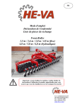
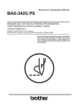
1
Table of Contents Reference Drawings..............................p. 2-3 Safety Instructions....................................p. 4 Before You Begin.....................................p. 5 Dimensions...............................................p. 6 Safety Guidelines......................................p. 7 Preparations.............................................p. 8 Assembly Instructions..........................p. 9-37 Cable Installations.............................p. 38-49 Cable Adjustments............................p. 50-51 Shroud Installation.............................p. 52-53 Adjustments.......................................p. 54-57 Warning, Safety & Maintenance........p. 58-59 Maintenance Schedule......................... 60-61 Phrase, Terms, Tips & Guidelines.....p. 62-63 Nutrition..................................................p. 64 Exercise Prescription..............................p. 65 Training Tips...........................................p. 66 Common Training Mistakes....................p. 67 Setting Up Your Personal Program.........p. 68 Determine Your Training Method............p. 69 Exercise Tips..........................................p. 70 Anatomy Chart........................................p. 71 Fitness Goals..........................................p. 72 Exercise Logs....................................p. 73-75 Streching & Flexibility.............................p. 76 Steching: Warm Up / Cool Down.......p. 77-86 Workout Exercises............................p. 88-90 Weight Ratios.........................................p. 91 Mainframe Parts List.........................p. 92-93 Hardware Parts List...........................p. 94-96 Obtaining Service....................................p. 97 Hardware Diagrams........................p. 98-100 Exploded View Diagrams..............p. 101-102 A s s e m b l y G9U OWNER’S & I n s t r u c t i o n s MANUAL T o t a l B o d y W o r k o u t D V D Follow the lead of international fitness presenter Geoff Bagshaw as he guides you step by step through a total health and conditioning program. Includes thorough explanations and demonstrations of over 50 exercises targeting all major muscle groups. The Body-Solid Total Body Workout is a “must have” for anyone truly serious about in-home training. Also includes: Complete stretching routine Importance of cardio training Body-Solid company profile Body-Solid Total Body Workout DVD Standard/Metric Cross-Reference Table The product hardware has been modified from Standard to Metric. When installing your machine, please use the table below to cross-reference between Standard and Metric hardware. Addendum G 9 U R e f e r e n c e D r a w i n g s Note: Due to continuing product improvements, specifications and designs are subject to change without notice. Even though we have prepared this manual with extreme care, neither the publisher nor the author can accept responsibility for any errors in, or omission from, the information given. 2 G9U Reference Drawings Note: Due to continuing product improvements, specifications and designs are subject to change without notice. Even though we have prepared this manual with extreme care, neither the publisher nor the author can accept responsibility for any errors in, or omission from, the information given. 3 I m p o r t a n t S a f e t y I n s t r u c t i o n s Before beginning any fitness program, you should obtain a complete physical examination from your physician. Il est conseille de subir un examen medical complet avant d’entreprendre tout programme d’exercise. Si vous avez des etourdissements ou des faiblesses, arretez les exercices immediatement. Antes de comenzar cualquier programma de ejercicios, deberias tener un examen fisico con su doctor. The G9U is designed for your enjoyment. By following these precautions and using common sense, you will have many safe and pleasurable hours of healthful exercise with your Body-Solid G9U. When using exercise equipment, you should always take basic precautions, including the following: • Read all instructions before using G9U. These instructions are written to ensure your safety and to protect the unit. the After assembly, you should check all functions to ensure correct operation. If you experience problems, first recheck the assembly instructions to locate any possible errors made during assembly. If you are unable to correct the problem, call the dealer from whom you purchased the machine or call 1-800-556-3113 for the dealer nearest you. • Do not allow children on or near the equipment. • Use the equipment only for its intended purpose as described in this guide. Do not use accessory attachments that are not recommended by the manufacturer. Such attachments might cause injuries. • Wear proper exercise clothing and shoes for your workout—no loose clothing. • Use care when getting on or off the unit. Obtaining Service • Do not overexert yourself or work to exhaustion. Please use this Owner’s Manual to make sure that all parts have been included in your shipment. When ordering parts, you must use the part number and description from this Owner’s Manual. Use only Body-Solid replacement parts when servicing this machine. Failure to do so will void your warranty and could result in personal injury. • If you feel any pain or abnormal symptoms, stop your workout immediately and consult your physician. • Never operate unit when it has been dropped or damaged. Return the equipment to a service center for examination and repair. • Never drop or insert objects into any opening in the equipment. For information about product operation or service, check out the official Body-Solid website at www.bodysolid.com or contact an authorized Body-Solid dealer or a Body-Solid factory-authorized service company or contact Body-Solid customer service at one of the following: • Always check the unit and its cables before each use. Make sure that all fasteners and cables are secure and in good working condition. • Do not use the equipment outdoors or near water. Toll Free: Phone: Fax: E-mail: Personal Safety During Assembly • It is strongly recommended that a qualified dealer assemble the equipment. Assistance is required. 1-800-556-3113 1-708-427-3555 1-708-427-3598 [email protected] Or write to: Body-Solid, Inc. Service Department 1900 S. Des Plaines Ave. Forest Park, IL 60130 USA • Before beginning assembly, please take the time to read the instructions thoroughly. • Read each step in the assembly instructions and follow the steps in sequence. Do not skip ahead. If you skip ahead, you may learn later that you have to disassemble components and that you may have damaged the equipment. Retain this Owner’s Manual for future reference. Part numbers are required when ordering parts. • Assemble and operate the G9U on a solid, level surface. Locate the unit a few feet from the walls or furniture to provide easy access. 4 B e f o r e Y o u B e g i n Thank you for purchasing the G9U. This gym is part of the Body-Solid line of quality strength training machines, which let you target specific muscle groups to achieve better muscle tone and overall body conditioning. To maximize your use of the equipment please study this Owner’s Manual thoroughly. Unpacking the Equipment Be careful to assemble all components in the sequence presented in this guide. The G9U is carefully tested and inspected before shipment. Body-Solid ships the unit in several pieces that require assembly. Ask for assistance during the assembly process. If any items are missing, contact the dealer from whom you purchased the unit or call 1-800-556-3113 for the dealer nearest you. Carefully unpack the boxes and lay the pieces on the floor near the area where you plan to use the equipment. OPTIONAL Equipment You will notice that most of the main frame parts are color coded with yellow dots, red dots, and blue dots on the individual pieces. These colored dots refer to different sections of the gym: Optional equipment that you can purchase through your dealer: Vertical Knee Raise Station GKR9. Yellow dots = Pec Dec section Red dots = Leg Extension/Chest Press section Blue dots = Leg Press section Pay special attention to the colored dots on the pads. They will help you to quickly place the pads in their correct position. After you have completely assembled G9U you can remove all colored dots. the 5 D i m e n s i o n s The room layout diagram below will help you decide the best placement for your G9U. The dimensions of the G9U are: width 6’6” X length 8’. The ceiling height requirement for the G9U is 7’. The usage space is: width 9’6” X length 11’10” (The usage space is the overall space needed for operation.) The diagrams below are without the optional Vertical Knee Raise Station GKR9. Height requirement Dimensions 6’ 6” 7’ 8’ Suggested usage space 9’ 6” 11’ 10” 6 S a f e t y G u i d e l i n e s Successful resistance training programs have one prominent feature in common...safety. Resistance training has some inherent dangers, as do all physical activities. The chance of injury can be greatly reduced or completely removed by using correct lifting techniques, proper breathing, maintaining equipment in good working condition, and by wearing the appropriate clothing. 1. It is highly recommended that you consult your physician before beginning any exercise program. This is especially important for individuals over the age of 35, or persons with pre-existing health problems. 2. Always warm up before starting a workout. Try to do a total body warm up before you start. It is especially important to warm up the specific muscle groups you are going to be using. This can be as simple as performing a warm up set of high repetitions and light weight for each exercise. 3. Use proper form. Focus on only working the muscle groups intended for the exercise you are doing. If there is strain elsewhere, you may need to re-evaluate the amount of weight that is involved with the lift. Keeping proper form also includes maintaining control through an theentire entirerange rangeofofmotion. motion. 4. Breath properly. Inhale during the eccentric phase of the exercise, and exhale during the lifting, or concentric phase. Never hold your breath during any part of an exercise. 5. Always wear the appropriate clothing and shoes when exercising. Wearing comfortable athletic shoes breathable clothing will will reduce the risk of injury. with good support and suitable, loose fitting, breathable clothing reduce the risk of injury. 6. Maintaining equipment in proper operating condition is of utmost importance for a safe resistance training program. Pulleys and cables should be checked for wear frequently and replaced as needed. Equipment should be lubricated as indicated by the manufacturer. 7. Read and study all warning labels on this machine. It is absolutely necessary that you familiarize yourself and all others with the proper operation of this machine prior to use. 8. Keep hands, limbs, loose clothing and long hair well out of the way of all moving parts. 9. Do not attempt to lift more weight than you can control safely. 10.Inspect the machine daily for loose or worn parts. If a problem is found do not allow the machine to be used until all parts are tightened or worn or defective parts are repaired or replaced. 7 P r e p a r a t i o n s CAUTION: To set up this unit, you will need assistance. Do not attempt assembly by yourself. You must review and follow the instructions in this Owner’s Manual. If you do not assemble and use the G9U according to these guidelines, you could void the Body-Solid warranty. Required Tools The tools that you must obtain before assembling the G9U include: CAUTION: Obtain assistance! Do not attempt to assemble the G9U by yourself. Review the Installation Requirements before proceeding with the following steps. 2mm Allen Key 3mm Allen Key 4mm Allen Key 5mm Allen Key The G9U unit comes in seven boxes. Be careful to assemble components in the sequence presented in this guide. 6mm Allen Key 8mm Allen Key NOTE: With so many assembled parts, proper alignment and adjustment is critical. While tightening the nuts and bolts, be sure to leave room for adjustments. 1/2” Open-End Wrench 9/16” Open-End Wrench 3/4” Open-End Wrench 13/16” Open-End Wrench 1/2” Box Wrench 9/16” Box Wrench 3/4” Box Wrench Installation Requirements Follow these installation requirements when assembling the G9U: Set up the G9U on a solid, flat surface. A smooth, flat surface under the machine helps keep it level. A level machine has fewer malfunctions. Provide ample space around the machine. Open space around the machine allows for easier access. Insert all bolts in the same direction. For aesthetic purposes, insert all bolts in the same direction unless specified (in text or illustrations) to do otherwise. Leave room for adjustments. Tighten fasteners such as bolts, nuts, and screws so the unit is stable, but leave room for adjustments. Do not fully tighten fasteners until instructed in the assembly steps to do so. Fill out and mail warranty card. 8 A s s e m b l y I n s t r u c t i o n s Professional installers are highly recommended! However, if you acquire the appropriate tools, obtain assistance, and follow the assembly steps sequentially, the process will take time, but is fairly easy. Assembly of the G9U takes professional installers about 3-5 hours to complete. If this is the first time you have assembled this type of equipment, plan on significantly more time. Assembly Tips IMPORTANT! Read all “Notes” on each page before beginning each step. Before you begin you should fold-out pages 98, 99, and 100. While you may be able to assemble the G9U using the illustrations only, important safety notes and other tips are included in the text. This is a quick reference guide that shows all hardware parts (in actual size) along with the corresponding key numbers on the assembly instructions. Some pieces may have extra holes that you will not use. Use only those holes indicated in the instructions and illustrations. NOTE: To find out the length of a particular bolt, measure its shank (the long, narrow part beneath the head). Refer to the following diagram: Do not fully tighten bolts until instructed to do so. Note: After assembly, you should check all functions to ensure correct operation. If you experience problems, first recheck the assembly instructions to locate any possible errors made during assembly. If you are unable to correct the problem, call the dealer from whom you purchased the machine or call 1-800-556-3113 for the dealer nearest you. mm Inch 9 STEP 1 Be careful to assemble all components in the sequence they are presented. NOTE: Finger tighten all hardware in this step. Do Not wrench tighten until end of step 5. A. Attach two Weight Stack Shims (28) to the bottom of Main Base Frame (A), and two Weight Stack Shims (28) to the bottom of Side Base Frame (B). Also, install two Frame Levelers (25) to the Main Base Frame (A) as shown. B. Attach Main Base Frame (A) to Side Base Frame (B) using: Two 73 (3/8”x 2 3/4” hex head bolt) Four 94 (3/8” washer) Two 91 (3/8” nylon lock nut) C. Attach two Foot Caps (19) to the ends of Front Base Frame (C). Attach Front Base Frame (C) to the Main Base Frame (A) using: One 65 (1/2”x 3” hex head bolt)* Two 93 (1/2” washer) One 90 (1/2” nylon lock nut) *NOTE: Only use one bolt (65) as shown. You will need the other side open for step 5. D. Attach one Foot Cap (19) to one end of Rear Base Frame (D). Leave the other side open, (depending on which side of the gym you want the low pulley station).* Connect Rear Base Frame (D) and Rear Vertical Frame (E) to Main Base Frame (A) as shown using: Two 64 (1/2”x 3 1/4” hex head bolt) Four 93 (1/2” washer) Two 90 (1/2” nylon lock nut) *NOTE: Depending on how much space you have available, and the configuration of your room, you can assemble this gym with the low pulley station on either side. E. Attach End Cap (13) to the top of Rear vertical Frame (E) and Frame Leveler (25) to Rear Base Frame (D). mm Inch 10 STEP 1 13 E 93 64 19 64 B 93 D 93 91 90 94 93 91 94 90 90 94 28 73 25 28 93 A 94 19 25 28 73 93 28 65 25 C 19 Above shows STEP 1 assembled and completed 11 STEP 2 Be careful to assemble all components in the sequence they are presented. NOTE: Finger tighten all hardware in this step. Do Not wrench tighten until end of step 5. A. Attach one Pulley (26) to Main Base Frame (A) and one Pulleys to Side Base Frame (B) as shown using: Two 76 (3/8”x 1 3/4” hex head bolt) Four 94 (3/8” washer) Two 91 (3/8” nylon lock nut) B. Attach two Pulley (34) to Main Base Frame (A) as shown using: One 72 (3/8”x 3” hex head bolt) Two 94 (3/8” washer) One 91 (3/8” nylon lock nut) C. Attach one Pulley (26) and Pulley Cable Guide (7) to the middle of the Main Base Frame (A) as shown using: One 76 (3/8”x 1 3/4” hex head bolt) Two 94 (3/8” washer) One 91 (3/8” nylon lock nut) D. Attach Front Vertical Frame (F) to Main Base Frame (A) as shown using: Two 64 (1/2”x 3 1/4” hex head bolt) Four 93 (1/2” washer) Two 90 (1/2” nylon lock nut) E. Attach Top Main Frame (G) to Front Vertical Frame (F) as shown using only one bolt: One 62 (1/2”x 5” hex head bolt) Two 93 (1/2” washer) One 90 (1/2” nylon lock nut) F. Attach Top Main Frame (G) and Pec Dec Frame (H) to Rear Vertical Frame (E) using: One 65 (1/2”x 3” hex head bolt)* One 64 (1/2”x 3 1/4” hex head bolt) Three 93 (1/2” washer) One 90 (1/2” nylon lock nut) *NOTE: The top bolt (65) goes into an internally threaded nut inside the Top Main Frame (G). mm Inch 12 STEP 2 62 G 93 65 93 93 90 H 93 90 64 93 14 E F 76 B 94 26 34 34 94 90 93 72 91 94 26 94 91 76 90 93 94 94 7 76 91 94 26 A 93 C 94 91 64 93 64 Above shows STEP 2 assembled and completed 13 STEP 3 Be careful to assemble all components in the sequence they are presented. NOTE: Finger tighten all hardware in this step. Do Not wrench tighten until end of step 5. A. Place two Weight Stack Risers (55) and two Rubber Donuts (31) onto Main Base Frame (A) as shown. Slide two Guide Rods (J) through the Rubber Donuts (31), the Weight Stack Risers (55), and into the Main Base Frame (A). B. Slide 20 Weight Stack Plates (51) onto the two Guide Rods (J). Make sure the opening in each weight stack plate, for the Weight Stack Pin (1), is facing outward. C. Attach Top Plate (8) to Selector Rod (6) using: One 77 (3/8”x 2” flat allen head) One 100 (3/8” spring lock washer) Slide Top Plate (8) and Selector Rod (6) onto Guide Rods (J). D. Place two Weight Stack Risers (55) and two Rubber Donuts (31) onto Side Base Frame (B) as shown. Slide two Guide Rods (J) through the Rubber Donuts (31), the Weight Stack Risers (55), and into the Side Base Frame (B). E. Slide 20 Weight Stack Plates (51) onto the two Guide Rods (J). Make sure the opening in each weight stack plate, for the Weight Stack Pin (1), is facing outward. F. Attach Top Plate (8) to Selector Rod (6) using: One 77 (3/8”x 2” flat allen head) One 100 (3/8” spring lock washer) Slide Top Plate (8) and Selector Rod (6) onto Guide Rods (J). G. Slide four Shaft Collars (22) onto the four Guide Rods (J) as shown.* *NOTE: Do not tighten the allen screw inside Shaft Collars (22), leave them loose. ≈ mm Inch 14 STEP 3 22 22 J 6 J J J 6 77 100 22 8 22 51 8 100 77 31 31 51 B 55 55 31 31 55 55 A Above shows STEP 3 assembled and completed 15 STEP 4 Be careful to assemble all components in the sequence they are presented. NOTE: Finger tighten all hardware in this step. Do Not wrench tighten until end of step 5. A. Attach Top Pulley Frame (K) to Top Main Frame (G) and Front Vertical Frame (F) as shown using: One 61 (1/2”x 5 1/4” hex head bolt) One 62 (1/2”x 5” hex head bolt) Four 93 (1/2” washer) Two 90 (1/2” nylon lock nut) B. Slide the four Shaft Collars (22) to the top of the four Guide Rods (J). Insert the top of the Shaft Collars (22) into Top Pulley Frame (K). Tighten the allen screw in each Shaft Collars (22). C. Insert two Pulleys (26) into Front Vertical Frame (F) as shown using: Four 10 (pulley spacer) Two 73 (3/8”x 2 3/4” hex head bolt) Two 91 (3/8” nylon lock nut) D. Insert two Pulleys (26) into Top Pulley Frame (K) using: Two 76 (3/8”x 1 3/4” hex head bolt) Four 94 (3/8” washer) Two 91 (3/8” nylon lock nut) E. Insert two Pulleys (26) into the pulley covers on the Top Main Frame (G) using: Two 76 (3/8”x 1 3/4” hex head bolt) Four 94 (3/8” washer) Two 91 (3/8” nylon lock nut) mm Inch 16 STEP 91 94 94 4 91 76 94 26 90 94 76 K 62 93 93 93 93 61 22 90 22 22 22 G 26 91 10 26 26 10 94 91 91 10 76 94 26 10 73 F Above shows STEP 4 assembled and completed 17 STEP 5 Be careful to assemble all components in the sequence they are presented. Most of the main frame parts in this step will have RED dots. NOTE: LEG EXTENSION SEAT PAD FRAME (S) AND THE LEG EXTENSION FRAME (L) ARE PRE-ASSEMBLED AS ONE PIECE. A. Attach Leg Extension Frame (L) and 2”x 6” Plate (M) to Front Vertical Frame (F) using: Two 61 (1/2”x 5 1/4” hex head bolt) Four 93 (1/2” washer) Two 90 (1/2” nylon lock nut) B. Attach the bottom of Leg Extension Frame (L) to Front Base Frame (C), through the opening left from step 1 using: One 60 (1/2”x 5 1/2” hex head bolt) Two 93 (1/2” washer) One 90 (1/2” nylon lock nut) C. Attach Leg Extention Arm (N) to Leg Extension Frame (L) using pre-installed Shaft (P) as shown. Tighten the two Allen Screws (88) to lock down Shaft (P) in Leg Extension Frame (L). Attach three End Caps (14) to the top of Leg Extension Frame (L) and each end of the Leg Extension Arm (N). D. Attach Leg Extension Pad Holder (Q) to Leg Extension Arm (N) using: One 63 (1/2”x 3 1/2” hex head bolt) Two 93 (1/2” washer) One 90 (1/2” nylon lock nut) Bronze Bushing (100) was pre-assembled, inside Leg Extension Arm (N). E. Attach Leg Pads (R) to Leg Extension Pad Holder (Q) using: Four 89 (5/16”x 3/4” round bolt)* Four 96 (5/16” spring lock washer) Four 95 (5/16” washer) F. Attach End Cap (15) onto the front of Leg Extension Seat Pad Frame (S). *Do NOT over-tighten these bolts. Tighten these bolts until spring lock washer is flat. Over - tightening these bolts will cause T - nuts in pads to strip out. NOTE: At this point you must make sure that the gym is level, stable and in the right location. You should now wrench tighten all bolts and nuts on the mainframe unit only. Do NOT re-tighten any of the pad bolts. Also, leave all pulley bolts finger-tight untill after STEP 20. mm Inch 18 STEP 5 61 93 F M 13 93 90 14 88 88 86 97 49 14 15 P 90 L 93 49 97 86 90 93 90 100 93 L N 100 C 93 63 93 Q 60 R 96 89 95 95 96 89 Above shows STEP 5 assembled and completed 19 STEP 6 Be careful to assemble all components in the sequence they are presented. Most of the main frame parts in this step will have RED dots. A. Attach Leg Extension Handles (U) to Leg Extension Seat Pad Frame (S) using: Two 72 (3/8”x 3” hex head bolt) Four 94 (3/8” washer) Two 91 (3/8” nylon lock nut) B. Attach Leg Extension Seat Pad (V) to Leg Extension Seat Pad Frame (S) using: Two 82 (5/16”x 2 3/4” hex head bolt)* Two 96 (5/16” spring lock washer) Two 95 (5/16” washer) *Do NOT over-tighten these bolts. Tighten these bolts untill spring lock washer is flat. Over - tightening these bolts will cause T - nuts in pads to strip out. C. Slide 4”x 8” Foam Rollers (12) onto Foam Roller Bar (W) and attach to Leg Extension Seat Pad Frame (S). Hold Foam Rollers (12) in place with 3” Plastic Washer (5) on the inside and Plastic Roller End Cap (18) on the outside as shown. Note: You should now wrench tighten all bolts and nuts in this step. Do NOT re-tighten any of the pad bolts or pulley bolts. mm Inch 20 STEP 6 91 94 V 91 94 94 U 72 94 F 72 95 U 95 96 96 18 82 5 82 12 5 S W 5 C 12 5 18 Above shows STEP 6 assembled and completed 21 STEP 7 Be careful to assemble all components in the sequence they are presented. Most of the main frame parts in this step will have RED dots. A. Attach two Leg Hold Downs (X) to the Front Vertical Frame (F) using: Two 64 (1/2”x 3 1/4” hex head bolt) Four 93 (1/2” washer) Two 90 (1/2” nylon lock nut) Slide two 4”x 8” Foam Rollers (12) onto the two Leg Hold Downs (X) and hold in place with two Plastic Roller End Caps (18). B. Insert two Plastic Bushings (21) into the Back Pad Holder (Y). Connect Back pad Holder (Y) to the Front Vertical Frame (F) using: Two 73 (3/8”x 2 3/4” hex head bolt) Four 94 (3/8” washer) Two 91 (3/8” nylon lock nut) C. Slide Back Pad Adjuster (Z) into the Back Pad Holder (Y) and hold in place with Ball Head Pop Pin (56) and Adjustment Bolt (112). Look inside Back Pad Adjuster (Z) and adjust the Adjustment Bolt (112) with Lock Nut (113) so that it will stop Back Pad Adjuster (Z) from sliding out, but will not interfere with Back Pad Insert (ZB) in the next step. D. Attach Upper Back Pad (ZA) to Back Pad Insert (ZB) using: Four 83 (5/16”x 1” hex head bolt)* Four 96 (5/16” spring lock washer) Four 95 (5/16” washer) *Do NOT over-tighten these bolts. Tighten these bolts until spring lock washer is flat. Over - tightening these bolts will cause T - nuts in pads to strip out. Slide Back Pad Insert (ZB) into Back Pad Adjuster (Z) and hold in place with Ball Head Pop Pin (56) and Adjustment Bolt (112). E. Attach Lower Back Pad (ZC) to Front Vertical Frame (F) using: Two 80 (5/16”x 5” hex head bolt)* Two 96 (5/16” spring lock washer) Two 95 (5/16” washer) *Do NOT over-tighten these bolts. Tighten these bolts until spring lock washer is flat. Over - tightening these bolts will cause T - nuts in pads to strip out. Note: You should now wrench tighten all bolts and nuts in this step. Do NOT re-tighten any of the pad bolts or pulley bolts. mm Inch 22 STEP 7 18 5 12 91 X 90 56 93 F 90 94 21 93 91 94 96 ZA 94 21 Z 73 83 Y 95 113 94 73 112 113 56 112 83 ZB 95 96 96 80 95 80 95 96 N X 12 93 5 18 64 ZC Q 93 64 C Above shows STEP 7 assembled and completed 23 STEP 8 Be careful to assemble all components in the sequence they are presented. Most of the main frame parts in this step will have RED dots. NOTE: You will need to loosen two Allen Screws (88) inside Seated Press Arm Support (AA), in order to remove shaft (AB). A. Attach Seated Press Arm Support (AA) to Top Main Frame (G) with Shaft (AB). Tighten Allen Screw (88) in Seated Press Arm Support (AA). B. Attach two Pulleys (26) to Seated Press Arm Support (AA) using: Two 76 (3/8”x 1 3/4” hex head bolt) Four 94 (3/8” washer) Two 91 (3/8” nylon lock nut) NOTE: You will need to loosen two Allen Screws (88), inside Seated Press Arm (AC), in order to remove shaft (AD). C. Attach Seated Press Arm (AC) to Seated Press Arm Support (AA) with Shaft (AD). Tighten two Allen Screws (88) in Seated Press Arm Support (AA) and in Seated Press Arm (AC). D. Attach two End Caps (14) to the top of Seated Press Arm Support (AA). Attach two End Caps (15) to the top of Seated Press Arm (AC). E. Attach Small Shroud (AE) to Seated Press Arm Support (AA) using: Four 86 (M8 x 16L round allen head) Four 97 ( M8 washer) Note: You should now wrench tighten all bolts and nuts in this step. Do NOT re-tighten any of the pad bolts or pulley bolts. mm Inch 24 STEP 8 G 14 14 88 88 AB AA 91 94 26 AE 94 97 76 86 91 94 15 AD 57 26 94 76 15 88 97 86 97 17 86 88 AC 24 24 Above shows STEP 8 assembled and completed 25 STEP 9 Be careful to assemble all components in the sequence they are presented. Most of the main frame parts in this step will have YELLOW dots. A. Attach three End Caps (13) to the front and sides of Pec Dec Frame (H), and attach Square Rubber Cap (32) to the top of the Pec Dec Frame (H). B. Slide Oilite Washer (9), Left Pec Dec Arm (AK) and then the Left Pec Dec Cam (AL) onto the left side of the Pec Dec Frame (H) as shown, Attach using: One 59 (1/2”x 1” hex head bolt) One 93 (1/2” washer) C. Slide Round End Cap (29) into Left Pec Dec Handle (AM) and attach to the Left Pec Dec Arm (AK) using: One 85 (5/16”x 3/4” flat allen head) One 96 (5/16” spring lock washer) Note: Left Pec Dec Handle (AM) should bend out, away from the the gym, as shown. D. Slide Oilite Washer (9), Right Pec Dec Arm (AP) and then the Right Pec Dec Cam (AQ) onto the Right side of the Pec Dec Frame (H) as shown, attach using: One 59 (1/2”x 1” hex head bolt) One 93 (1/2” washer) E. Slide Round End Cap (29) into Right Pec Dec Handle (AR) and attach to the Right Pec Dec Arm (AP) using: One 85 (5/16”x 3/4” flat allen head) One 96 (5/16” spring lock washer) Note: Right Pec Dec Handle (AR) should bend out, away from the gym, as shown. F. Attach two Chrome Collars (106) to the top of Left Pec Dec Handle (AM) and Right Pec Dec Handle (AR) using: Two 88 (5/16” allen screw) preinstalled You should now wrench tighten all bolts and nuts in this step. Do NOT re-tighten any of the pad bolts or pulley bolts. mm Inch 26 STEP 59 9 93 59 AL 93 AQ AK 106 88 50 AM 96 85 AP 9 88 32 106 50 13 9 13 H AR 13 85 96 Above shows STEP 9 assembled and completed 27 STEP 10 Be careful to assemble all components in the sequence they are presented. Most of the main frame parts in this step will have YELLOW dots. A. Slide Plastic Bushing (23) into the receptacle at the bottom of the Rear Vertical Frame (E) as shown. Attach Hydraulic Seat Adjuster (AU) to the inside of the receptacle at the bottom of the Rear Vertical Frame (E) using: One 72 (3/8”x 3” hex head bolt) Two 94 (3/8” washer) One 91 (3/8” nylon lock nut) B. Attach two End Caps (13) to the front and back of Seat Pad Frame (AV). Slide Seat Pad Frame (AV) into receptacle at the bottom of Rear Vertical Frame (E), and attach to the top of Hydraulic Seat Adjuster (AU) using: One 74 (3/8”x 2 1/2”hex head bolt) Two 94 (3/8” washer) One 91 (3/8” nylon lock nut) Insert Pop Pin (48) into the threaded opening in the receptacle at the bottom of the Rear Vertical Frame (E). C. Attach Seat Pad (AW) to Seat Pad Frame (AV) using: Two 82 (5/16”x 2 3/4” hex head bolt)* Two 96 (5/16” spring lock washer) Two 95 (5/16” washer) *Do NOT over-tighten these bolts. Tighten these bolts until spring lock washer is flat. Over - tightening these bolts will cause T - nuts in pads to strip out. D. Attach Back Pad (AX) to Rear Vertical Frame (E) using: Two 82 (5/16”x 2 3/4” hex head bolt)* Two 96 (5/16” spring lock washer) Two 95 (5/16” washer) *Do NOT over-tighten these bolts. Tighten these bolts until spring lock washer is flat. Over - tightening these bolts will cause T - nuts in pads to strip out. Note: You should now wrench tighten all bolts and nuts in this step. Do NOT re-tighten any of the pad bolts or pulley bolts. mm Inch 28 STEP 10 AW AX 14 AV 91 95 94 E 96 82 95 96 95 82 14 95 96 94 74 82 96 82 23 AU 91 94 48 94 72 D Above shows STEP 10 assembled and completed 29 STEP 11 Be careful to assemble all components in the sequence they are presented. A. Attach two End Caps (13) to the ends of the Low Pulley Frame (AY). Connect Low Pulley Frame (AY) to the Main Base Frame (A) using: One 98 (M10 washer) One 87 (M10 x 16L round allen head) B. Attach Foot Brace (AZ) to the open side of Rear Base Frame (D) using: One 73 (3/8”x 2 3/4” hex head bolt) Two 94 (3/8” washer) One 91 (3/8” nylon lock nut) C. Attach two End Caps (16) and Grip Tape (33) to Foot Brace (AZ) as shown. D. Attach Pulley (26) to Low Pulley Frame (AY) using: One 76 (3/8”x 1 3/4” hex head bolt) Two 94 (3/8” washer) One 91 (3/8” nylon lock nut) Note: You should now wrench tighten all bolts and nuts in this step. Do NOT re-tighten any of the pad bolts or pulley bolts. mm Inch 30 STEP 11 26 91 87 94 94 98 76 16 13 13 AY 91 94 D A 33 94 33 73 AZ 16 Above shows STEP 11 assembled and completed 31 STEP 12 Be careful to assemble all components in the sequence they are presented. Most of the main frame parts in this step will have BLUE dots. A. Attach Leg Press Support (BA) to Main Base Frame (A) using: Two 73 (3/8”x 2 3/4” hex head bolt) Four 94 (3/8” washer) Two 91 (3/8” nylon lock nut) B. Attach Leg Press Main Frame (BB) to Leg Press Support (BA) using: Four 73 (3/8”x 2 3/4” hex head bolt) Eight 94 (3/8” washer) Four 91 (3/8” nylon lock nut) C. Attach Leg Press Main Frame (BB) to Side Base Frame (B) using: Two 73 (3/8”x 2 3/4” hex head bolt) Four 94 (3/8” washer) Two 91 (3/8” nylon lock nut) D. Attach End Cap (15) to the top of Leg Press Main Frame (BB). Attach two Frame Levelers (25) to the bottom of Leg Press Main Frame (BB). Attach Pulley (26) to Leg Press Main Frame (BB) using: One 76 (3/8”x 1 3/4” hex head bolt) Two 94 (3/8” washer) One 91 (3/8” nylon lock nut) E. Attach two Foot Caps (20) to each end of the Leg Press Front (BC). Attach Leg Press Front (BC) to the front of Leg Press Main Frame (BB) using: Two 65 (1/2”x 3” hex head bolt) Four 93 (1/2” washer) Two 90 (1/2” nylon lock nut) Note: You should now wrench tighten all bolts and nuts in this step. Do NOT re-tighten any of the pad bolts or pulley bolts. mm Inch 32 STEP 12 73 94 73 73 94 73 94 94 BB 15 73 73 94 94 76 25 94 94 91 91 94 90 20 26 93 BB 91 94 94 94 91 B 91 93 65 90 BA 93 25 93 65 BC 91 91 20 94 94 94 73 94 A 73 Above shows STEP 12 assembled and completed 33 STEP 13 Be careful to assemble all components in the sequence they are presented. Most of the main frame parts in this step will have BLUE dots. A. Slide two Pillow Block Bearings (45) onto lower shaft on Main Leg Press Pivot (BD) and leave allen screws loose. NOTE: Allen screws should both be on the inside. B. Attach two Pillow Block Bearings (45) to the plate at the front of Leg Press Frame (BB) using: Four 66 (1/2”x 1 3/4” hex head bolt) Eight 93 (1/2” Washer) Four 90 (1/2” nylon lock nut) C. Attach Front Leg Press Pivot (BE) and Shaft (BF) to Leg Press Frame (BB) as shown using: Two 41 (leg press oilite bushing) Two 90 (1/2” nylon lock nut) D. Attach Foot Plate T-frame (BG) and Shaft (BF) to Front Leg Press Pivot (BE) as shown using: Two 41 (leg press oilite bushing) Two 90 (1/2” nylon lock nut) E. Attach Foot Plate T-frame (BG) and Shaft (BF) to Main Leg Press Pivot (BD) as shown using: Two 41 (leg press oilite bushing) Two 90 (1/2” nylon lock nut) F. Attach Foot Plate (BR) to Foot Plate T-frame (BG) using: Two 64 (1/2”x 3 1/4” hex head bolt) Four 93 (1/2” washer) Two 90 (1/2” nylon lock nut) Attach three End Caps (14) to each side of Foot Plate (BR) and front of Foot Plate T-frame (BG). Note: You should now wrench tighten all bolts and nuts in this step. Do NOT re-tighten any of the pad bolts or pulley bolts. mm Inch 34 STEP 14 64 93 14 13 64 90 93 BG BF BR 93 93 90 90 90 BF 14 90 90 BE BD 90 BF 66 66 93 93 BB 90 45 66 66 93 93 90 93 90 93 93 93 45 90 BC 90 There are two small alen set screws in each Pillow Block Bearing(45). For best alignment of this system you should loosen all allen set screws before instlling the Pillow Block Bearings(45) The last end final step of the assembly process is to wrench tighten all of these allen set screw in all the Pillow Block Bearings(45) Above shows STEP 13 assembled and completed 35 STEP 14 Be careful to assemble all components in the sequence they are presented. Most of the main frame parts in this step will have BLUE dots. A. Slide Round End Cap (29) onto Leg Press Handles (BH). Attach Leg Press Handles (BH) onto Leg Press Frame (BB) using: Two 71 (3/8”x 3 1/4” hex head bolt) Four 94 (3/8” washer) Two 91 (3/8” nylon lock nut) B. Attach two Seat Pad Flange (BL) to Leg Press Frame (BB) using: One 70 (3/8”x 3 1/2” hex head bolt) Two 94 (3/8” washer) One 91 (3/8” nylon lock nut) C. Attach Leg Press Seat Pad (BM) to the two Seat Pad Flange (BL) using: Two 83 (5/16”x 1” hex head bolt)* Two 96 (5/16” spring lock washer) Two 95 (5/16” washer) *Do NOT over-tighten these bolts. Tighten these bolts until spring lock washer is flat. Over - tightening these bolts will cause T - nuts in pads to strip out. D. Attach Leg Press Seat Pad (BM) to Leg Press Frame (BB) using: One 81 (5/16”x 3 1/4” hex head bolt)* One 96 (5/16” spring lock washer) One 95 (5/16” washer) *Do NOT over-tighten this bolt. Tighten this bolt until spring lock washer is flat. Over - tightening this bolt will cause T - nut in pad to strip out. E. Slide Plastic Bushing (23) into Leg Press Frame (BB). Slide Leg Press Back Pad Frame (BP) into Plastic Bushing (23) and hold in place with T-Shaped Pop Pin (48). Attach End Cap (14) to the bottom of Leg Press Back Pad Frame (BP). F. Attach Leg Press Back Pad (BQ) to Leg Press Back Pad Frame (BP) using: Four 83 (5/16”x 1” hex head bolt)* Four 96 (5/16” spring lock washer) Four 95 (5/16” washer) *Do NOT over-tighten these bolts. Tighten these bolts until spring lock washer is flat. Over - tightening these bolts will cause T - nuts in pads to strip out. Note: You should now wrench tighten all bolts and nuts in this step. Do NOT re-tighten any of the pad bolts or pulley bolts. mm Inch 36 STEP 95 96 14 83 BM 83 95 BQ 71 96 83 95 96 95 96 83 94 BH 71 94 48 95 70 96 BP 94 14 81 BL 95 23 BL 83 94 96 91 95 BH 96 94 91 94 91 83 Above shows STEP 14 assembled and completed 37 STEP 15 Be careful to assemble all components in the sequence they are presented. NOTE: All pulleys are the 4 1/4” diameter Pulleys (26), except where noted. Lat Pulldown Cable (36) Ball Stop End Metal Ball End 13’ 8” 4170 mm A. Start at the front of the gym. Insert metal ball end of the Lat Pulldown Cable (36) into Top Main Frame (G), through the frame and out through the second opening. Pull entire length of Cable (36) all the way through. Install Pulley (A1) into the first opening, and Pulley (A2) into the second opening. Be sure that Cable (36) rides on top of these pulleys. Install each pulley using: One 73 (3/8”x 2 3/4” hex head bolt) Two 10 (pulley spacer) One 91 (3/8” nylon lock nut) B. Remove Pulley (A3), route Cable (36) inside pulley housing as shown, and re-install Pulley (A3). C. Remove Pulley (A4), route Cable (36) around Pulley (A4) as shown, and re-install Pulley (A4). D. Remove Pulley (A5), route Cable (36) inside pulley housing as shown, and reinstall Pulley (A5). E. Route Cable (36) over Pulley (A6). Route Cable (36) down through opening in the small arm sticking out of the Front Vertical Frame (F). Pull entire length of Cable (36) through. F. Route Cable (36) throught the Double Pulley Holder (130) as shown and install Pulley (A7) using: One 76 (3/8”x 1 3/4” hex head bolt) Two 94 (3/8” washer) One 91 (3/8” nylon lock nut) G. Route Cable (36) up and over Pulley (A8)* and then down toward weight stack. *Note: Leave the bolt going through Pulley (A8) hand tight until the end of Cable Adjustments in Step 21. H. Remove Bolt (56) from Selector Rod Top Bolt (52), slide Cable (36) through Selector Rod Top Bolt (52). Attach Cable End Shaft (135) and tighten Allen Screw (136). Pull Cable (36) tight, so Cable End Shaft (135) fits inside Selector Rod Top Bolt (52). Reinstall Bolt (56) in Selector Rod Top Bolt (52). mm Inch 38 STEP A8 Start at high pully station by inserting the Metal Ball End here. 15 A4 A2 A1 G 36 AA F A3 A5 130 A6 A7 6 99 36 52 52 79 136 135 1/2" (at least) 135 79 54 53 6 6 ! WARNING ! Selectoe Eod Top Bolt(52) must be threaded a minumum of 1/2" into the Selector Rod (6),and Jam Nut (54) tightened securely against spring lock washer (53) to ensure proper connection.Check the Jam Nut (54) once a week to make sure it is tight. Above shows STEP 15 assembled and completed 39 STEP 16 Be careful to assemble all components in the sequence they are presented. NOTE: All pulleys are the 4 1/4” diameter Pulleys (26), except where noted. Leg Extension Cable (37) Stamped Eye End Stamped Eye End 2635mm 8’ 7 1/2” Short Cable (40) Stamped Eye End Chain End 520mm 1’ 8 1/2” A. Attach either stamped eye end of Leg Extension Cable (37) to Leg Extension Arm (N) using: One 84 (5/16”x 1 1/2” flat allen head) Two 4 (3/4” steel bushing) One 2 (1/2” steel sleeve) One 92 (5/16” nylon lock nut) B. Route Cable (37) under Pulley (B1) and up toward Double Pulley Holder (52). C. Route Cable (37) Inside the bottom portion of Double Pulley Holder (130) as shown, and install Pulley (B2) using: One 76 (3/8”x 1 3/4” hex head bolt) Two 94 (3/8” washer) One 91 (3/8” nylon lock nut) D. Attach stamped eye end of Short Cable (40) to Cable (37) using a Snap Link (43). Attach the chain end of Cable (40) to the Main Base Frame (A) using another Snap Link (43). mm Inch 40 STEP 16 130 B2 43 40 Short Cable 43 B1 A N 37 Leg Extension Cable 92 84 4 41 2 37 14 4 STEP 17 Be careful to assemble all components in the sequence they are presented. NOTE: All pulleys are the 4 1/4” diameter Pulleys (26), except where noted. Pec Dec Cable (38) Metal Ball End Metal Ball End 1890mm 6’ 2 1/2” A. Attach metal ball end of Pec Dec Cable (38) to Right Pec Dec Cam (AQ) and route under Top Main Frame (G). B. Attach the other ball end of Cable (38) to Left Pec Dec Cam (AL). C. Attach Pulley (C1) to flange on Top Main Frame (G) behind Right Pec Dec Cam (AQ) using: One 76 (3/8”x 1 3/4” hex head bolt) One 7 (pulley cable guide) Two 94 (3/8” washer) One 91 (3/8” nylon lock nut) Route Pec Dec Cable (38) over Pulley (C1). D. Attach Pulley (C2) to flange on Top Main Frame (G) behind Left Pec Dec Cam (AL) using: One 76 (3/8”x 1 3/4” hex head bolt) One 7 (pulley cable guide) Two 94 (3/8” washer) One 91 (3/8” nylon lock nut) Route Pec Dec Cable (38) over Pulley (C2). E. Hang Pec Dec Pulley Holder (131) on Pec Dec Cable (38) as shown and install Pulley (C3) using: One 76 (3/8”x 1 3/4” hex head Bolt) Two 94 (3/8” washer) One 91 (3/8” nylon lock nut) mm Inch 42 STEP AQ 17 38 Pec Dec Cable C1 AL G C2 C3 E 131 43 STEP 18 Be careful to assemble all components in the sequence they are presented. NOTE: All pulleys are the 4 1/4” diameter Pulleys (26), except where noted. Ab Crunch Cable (39) Ball Stop End Chain End 1545mm A. 5’ 1” Insert chain end of the Ab Crunch Cable (39) into the opening above Back Pad (AX), and pull entire length through. NOTE: You will now need the 3” diameter Pulley (27), for the next step. B. Insert 3” Pulley (27) into the Rear Vertical Frame (E) under Cable (39) using: Two 10 (pulley spacer) One 73 (3/8”x 2 3/4” hex head bolt) One 91 (3/8” nylon lock nut) C. Attach chain end of Cable (39) to the bottom of Pec Dec Pulley Holder (131). D. Hang Pulley (D2) from on Cable (39) as shown using two Pulley Plates (132) and: One 76 (3/8”x 1 3/4” hex head bolt) Two 94 (3/8” washer) One 91 (3/8” nylon lock nut) mm Inch 44 STEP 18 E C3 D1 131 43 73 10 10 91 39 AX 27 Ab Crunch Cable D2 132 45 STEP 19 Be careful to assemble all components in the sequence they are presented. NOTE: All pulleys are the 4 1/4” diameter Pulleys (26), except where noted. Low Pulley Cable (35) Metal Ball End Ball Stop End 4425mm 14”6” A. Insert metal ball end of Low Pulley Cable (35) at Low Pulley Frame (AY). Insert metal ball end of Cable (35) under Pulley (E1). B. Route Cable (35) over Pulley (E2), and attach Pulley (E2) to the bottom of Pulley Plates (132) using: One 76 (3/8”x 1 3/4” hex head bolt) Two 94 (3/8” washer) One 91 (3/8” nylon lock nut) C. Route Cable (35) under Pulley (E3). D. Route Cable (35) over Pulleys (E4) and (E5). E. Route Cable (35) through Pulley Holder With Hook (133) as shown. Install Pulley (E6) using: One 76 (3/8”x 1 3/4” hex head bolt) Two 94 (3/8” washer) One 91 (3/8” nylon lock nut) F. Remove Pulley (E7) from pulley housing. Insert Cable (35) into pulley housing as shown and reinstall Pulley (E7).* *Note: Leave the bolt going through Pulley (E7) hand tight until the end of Cable Adjustments in Step 21. G. Remove Bolt (56) from Selector Rod Top Bolt (52), slide Cable (35) through Selector Rod Top Bolt (52). Attach Cable End Shaft (135) and tighten Allen Screw (136). Pull Cable (36) tight, so Cable End Shaft (135) fits inside Selector Rod Top Bolt (52). Reinstall Bolt (56) in Selector Rod Top Bolt (52). mm Inch 46 STEP E7 K G E4 E5 132 E6 133 E2 6 35 Low Pulley Cable E1 AY E3 99 36 52 52 Low Pulley Cable 79 135 (at least) 1/2" 136 79 54 53 135 6 6 ! WARNING ! Selectoe Eod Top Bolt(52) must be threaded a minumum of 1/2" into the Selector Rod (6),and Jam Nut (54) tightened securely against spring lock washer (53) to ensure proper connection.Check the Jam Nut (54) once a week to make sure it is tight. 47 19 STEP 20 Be careful to assemble all components in the sequence they are presented. NOTE: All pulleys are the 4 1/4” diameter Pulleys (26), except where noted. Leg Press Cable (34) Stamped Eye End Chain End 4300mm 14’1” A. Attach the chain end of Leg Press Cable (34) to Leg Press Frame (BB) with Snap Link (43). B. Route Cable (34) into the top of pulley housing in Leg Press Pivot (BD) as shown and install Pulley (F1) using: One 75 (3/8”x 2” hex head bolt) Two 94 (3/8” washer) One 91 (3/8” nylon lock nut) C. Route Cable (34) over Pulley (F2) as shown. D. Route Cable (34) back into the bottom of pulley housing in Leg Press Pivot (BD) and install Cable (34) over Pulley (F3) using: One 75 (3/8”x 2” hex head bolt) Two 94 (3/8” washer) One 91 (3/8” nylon lock nut) E. Route Cable (34) through the opening in the support column of Leg Press Frame (BB). Pull entire length of Cable (34) through. Route Cable (34) around Pulley (F4) as shown and toward Pulley (F5). F. Route Cable (34) under Pulley (F5) and up to the bottom of Pulley Holder With Hook (133). Attach Cable (34) to Pulley Holder With Hook (133). Note: You should now wrench tighten all bolts and nuts. Except the pad bolts, Never re-tighten any pad bolts. mm Inch 48 STEP 20 E6 133 Leg Press Cable 34 BD BB 43 F4 F1 F5 1 F3 49 STEP 21 NOW IS THE TIME TO MAKE ALL NECESSARY CABLE ADJUSTMENTS After cable installation is complete you must check all cables for proper tension. Obvious signs that cable tension problems exist include: Top Plates (8) do not rest directly on the top weight stack plates. The holes in the Selector Bar (6) do not line up with the holes in the Weight Stack Plates. Cable(s) are sloppy and there is no resistance from the weight stack for the first few inches of the exercise. There are TEN areas for cable adjustment on the G9U: A TWO Selector Rod Top Bolts (52) B THREE Rubber Stops (42) C THREE Adjustable Chains on cables (34), (39), (40). D TWO Adjustments in pulley housing on Top Pulley Frame (K) SEE NOTE 1 AND NOTE 2 ON PAGE 51. If there is too much tension, and the Top Plate (8) is not resting directly on the top weight stack plate: 1st.- Turn and tighten the Rubber Stop (B). 2nd.- Move Snap Link (C) to add a link. 3rd.- Move pulley down to a lower hole in pulley housing on Top Pulley Frame (K). If there is to much play or excessive slack: 1st.- Turn and loosen the Rubber Stop (B). 2nd.- Move Snap Link (C) to minus a link. 3rd.- Move Pulley up to a higher hole in pulley housing on Top Pulley Frame (K). 4th.- Screw the Selector Bar Top Bolt (52) farther into the Selector Bar (6) of the Weight Stack. NOTE: Cables should be inspected daily and adjusted periodically to ensure safe and smooth operation. NOTE: After cable adjustment is complete, go back and tighten two bolts in pulley housing on Top Pulley Frame (K). nn Jodi 50 STEP B.Rubber Stop(42) 21 NOTE 1 Before beginning final cable adjustments,be sure that both of these pulley housing nutt-up as close as possible to the welded stops on the frame pieces. Tighten K D D 1 C A 8 A 8 B C C B Selector Rod Top Bolt NOTE 2 52 ! WARNING ! Selector Eod Top Bolt(52) Must be threaded a minumum of a 1/2" into the Selector Rod (6), and Lock Nut (54) tightened securely to ensure proper connection. 51 Check lock nut weekly to be sure it is tight and locked on to the Selector Eod. (See page 61) STEP 22 Be careful to assemble all components in the sequence they are presented. SEE NOTE 1: A. Apply weight stack numbers to weight stack Top Plate (8) and each Weight Stack Plate as shown. SEE NOTE 2: Note the shape of each shroud for proper placement. B. Weight Stack Shroud (CA) is pre-assembled with Shroud Insert (CB). Attach Weight Stack Shroud (CA) to the side of the weight stack as shown. Bolt onto Side Base Frame (B) and Top Pulley Frame (K) using: Two 87 (M10 x16L round allen head) Two 98 (M10 washer) C. Attach Weight Stack Shroud (CC) to the other side of this weight stack using: Two 87 (M10 x16L round allen head) Two 98 (M10 washer) D. Weight Stack Shroud (CD) is pre-assembled with Shroud Insert (CE). Attach Weight Stack Shroud (CD) to the side of the weight stack as shown. Bolt onto Main Base Frame (A) and Top Pulley Frame (K) Using: Two 87 (M10 x16L round allen head) Two 98 (M10 washer) E. Attach Weight Stack Shroud (CF) to the other side of this weight stack using: Two 87 (M10 x16L round allen head) Two 98 (M10 washer) mm Inch 52 STEP 22 CC 3/4" flat side CA 2" flat side 3/4" flat side CF NOTE 2 This is the top view of the four Weight Stack Shrouds.Note the shape of each shroud for proper placement Above shows STEP 22 assembled and completed NOTE 1 Apply weight stack numbers to the Weight Stack Plates(51).Start at the Top Plate(8)with the number 1,end the first plate should be number 2.The following Weight Stack Plates (51)should be numbered in sequential order down through the stack. 87 98 87 98 98 87 #2 CC CD #1 98 CE CF 87 CB 98 87 CA 87 98 98 87 K 98 87 B A 53 A d j u s t m e n t s Congratulations! You are done. After assembly, you should check all functions to ensure correct operation. If you experience problems, first recheck the assembly instructions to locate any possible errors made during assembly. If you are unable to correct the problem, call the dealer from whom you purchased the machine or call 1-800-556-3113 for the dealer nearest you. Note: If any bolts seem to loosen periodically, use Loctite 242 for a long-term cure. This gym is capable of a variety of different exercises, as well as, smooth and user-friendly adjustment features. The following pages of adjustments will help you to familiarize yourself with your new gym. We hope you are completely satisfied with this product and wish you many years of enjoyment. 1. SEATED PRESS ARMS (AC) ADJUSTMENT A. Grasp the Seated Press Arm (AC) with your left hand. B. Pull the Ball Head Pop Pin (57) with your right hand to release the Seated Press Arm. C. Adjust the Seated Press Arm to the desired position (depending on the exercise you are performing). D. Release the Ball Head Pop Pin, and make sure it is fully engaged into the selector hole. 2. UPPER BACK PAD (ZA) ADJUSTMENT A. Grasp the Upper Back Pad (ZA). B. Pull the Ball Head Pop Pin on top of the Back Pad Holder to release Back Pad Adjuster. There are two adjustment positions. C. For certain exercises you may wish to fine Tune your adjustment by pulling the Ball Head Pop Pin on the side of the Back Pad Adjuster, this will release the Back Pad Insert. There are six additional adjustment positions. D. Adjust the Upper Back Pad (ZA) to the desired position. E. Release the Ball Head Pop Pin(s) and make sure they are fully engaged into the selector hole(s) of the Back Pad Insert(s). 3. LEG EXTENTION SEAT PAD (V) ADJUSTMENT A. Grasp the Leg Extention Seat Pad (V). B. Turn the T-Shaped Pop Pin (48) counter clockwise to unlock it, and then pull the Pop Pin to release the Leg Extention Seat Pad. C. Adjust the Leg Extention Seat Pad (V) to the desired position. D. Release the T-Shaped Pop Pin (48) and make sure it is fully engaged into the selector hole of the Leg Extention Seat Pad Frame. Turn Pop Pin clockwise to lock it in place. 54 1. Pull Ball Head Pop Pin(57) Adjust Seated Press Arm(AC) (Reverse view drawing) 2. 3. Leg Extensions Seat Pad(v) Adjust Upper Back Pad(ZA) top Ball Head Pop Pin (56) Pull T-Shaped Pop Pin(48) side Ball Head Pop Pin(56) ! WARNING ! Pay special attention to the plunger on this Pop Pin (48). Always be sure that the plunger is fully engaged into the hole you select.Also,be sure that the spring in the Pop Pin (48) operates freely.Failure to do so may reault in serious injury. 55 Make sure Pop PIn(48) is fully engahed into selector hole,and then turn clockwise to lock it in place. A d j u s t m e n t s 4. PEC DEC ARM (AK) or (AP) ADJUSTMENT A. Grasp Pec Dec Arm (AK) or (AP). B. Pull the Ball Head Pop Pin (50) to release the Pec Dec Arm (AK) or (AP). C. Adjust the Pec Dec Arm to the desired position. D. Release the Ball Head Pop Pin (50) and make sure that it is fully engaged into the selector hole. 5. PEC DEC SEAT PAD (AW) ADJUSTMENT A. Grasp the Pec Dec Seat Pad (AW). B. Turn the T-Shaped Pop Pin (48) counter clockwise to unlock it, then pull to release the Pec Dec Seat. C. Adjust the Pec Dec Seat Pad to the desired position. D. Release the T-Shaped Pop Pin (48) and make sure that it is fully engaged into the Pec Dec Seat Frame (AV). Turn clockwise to lock it in place. 6. LEG PRESS BACK PAD (BQ) ADJUSTMENT A. Grasp the Leg Press Back Pad (BQ). B. Turn the T-Shaped Pop Pin (48) counter clockwise to unlock it, then pull to release the the Leg Press Back Pad. C. Adjust the Leg Press Back Pad to the desired position. D. Release the T-Shaped Pop Pin (48) and make sure that it is fully engaged into the selector hole in the Leg Press Back Pad Frame. Turn clockwise to lock it in place. 56 4. Adjust Pec Dec Arm(AK)or(AP) Pull Ball Head Pop Pin (50) ! WARNING ! ! Pay special attention to the plunger on this Pop Pin (48). Always be sure that the plunger is fully engaged into the hole you select.Also,be sure that the spring in the Pop Pin (48) operates freely.Failure to do so may reault in serious injury. WARNING ! Pay special attention to the plunger on this Pop Pin (48). Always be sure that the plunger is fully engaged into the hole you select.Also,be sure that the spring in the Pop Pin (48) operates freely.Failure to do so may reault in serious injury. 5. 6. Pull T-Shaped Pop Pin(48) Pull T-Shaped Pop Pin(48) Make sure Pop PIn is fully engahed into selector hole,and then turn clockwise to lock it in place. Make sure Pop PIn is fully engahed into selector hole,and then turn clockwise to lock it in place. 57 G 9 U KEY# QTY A B C D E F G H J K L M N P Q S T U W X Y Z ZB AA AB AC AD AK AL AM AP AQ AR AU AV AY AZ 1 1 1 1 1 1 1 1 4 1 1 1 1 1 1 1 1 2 1 2 1 1 1 1 1 1 1 1 1 1 1 1 1 1 1 1 1 P a r t s L i s t PART# DESCRIPTION E37MBF-A E37SBF-B E37FBF-C E37RBF-D E37RVF-E E37FVF-F E37TMF-G E37PDF-H E37GR-J E37TPF-K E37LEF-L E37P-M E37LEA-N E37S-P E37LEPH-Q E37LESPF-S E37HSA-T E37LEH-U E37FRB-W E37LHD-X E37BPH-Y E37BPA-Z E37BPI-ZB E37SPAS-AA E37S-AB E37SPA-AC E37S-AD E37LPDA-AK E37LPDC-AL E37LPDH-AM E37RPDA-AP E37RPDC-AQ E37RPDH-AR E37HSA-AU E37PDSF-AV E37LRF-AY E37FB-AZ MAIN BASE FRAME SIDE BASE FRAME FRONT BASE FRAME REAR BASE FRAME REAR VERTICAL FRAME FRONT VERTICAL FRAME TOP MAIN FRAME PEC DEC FRAME GUIDE ROD TOP PULLEY FRAME LEG EXTENSION FRAME 2”X 6” PLATE LEG EXTENSION ARM 2” SHAFT LEG EXTENSION PAD HOLDER LEG EXTENSION SEAT PAD FRAME HYDRAULIC SEAT ADJUSTER (PRE-INSTALLED) LEG EXTENSION HANDLES FOAM ROLLER BAR LEG HOLD DOWN BACK PAD HOLDER BACK PAD ADJUSTER BACK PAD INSERT SEATED PRESS ARM SUPPORT 9” SHAFT SEATED PRESS ARMS 11 3/4” SHAFT LEFT PEC DEC ARM LEFT PEC DEC CAM LEFT PEC DEC HANDLE RIGHT PEC DEC ARM RIGHT PEC DEC CAM RIGHT PEC DEC HANDLE HYDRAULIC SEAT ADJUSTER PEC DEC SEAT FRAME LOW PULLEY FRAME FOOT BRACE Part numbers are required when ordering parts. 92 G 9 U KEY# QTY BA BB BC BD BE BF BG BH BL BP BR 1 1 1 1 1 3 1 2 2 1 1 P a r t s L i s t PART# DESCRIPTION E37LPC-BA E37LPF-BB E37LPF-BC E37LPP-BD E37FLPP-BE E37S-BF E37FPTF-BG E37LPH-BH E37SPF-BL E37LPBF-BP E37FP-BR LEG PRESS CONNECTION LEG PRESS FRAME LEG PRESS FRONT LEG PRESS PIVOT FRONT LEG PRESS PIVOT 3” SHAFT FOOT PLATE T-FRAME LEG PRESS HANDLES SEAT PAD FLANGE LEG PRESS BACK PAD FRAME FOOT PLATE S h r o u d KEY# QTY AE CA CB CC CD CE CF 1 1 1 1 1 1 1 QTY R V ZA ZC AW AX BM BQ 2 1 1 1 1 1 1 1 L i s t PART# DESCRIPTION E37SPHS-AE E37WSS-CA E37SI-CB E37WSS-CC E37WSS-CD E37SI-CE E37WSS-CF SEATED PRESS HINGE SHROUD WEIGHT STACK SHROUD SHROUD INSERT WEIGHT STACK SHROUD WEIGHT STACK SHROUD SHROUD INSERT WEIGHT STACK SHROUD P a d s KEY# ( c o n t i n u e d ) L i s t PART# DESCRIPTION E37LP-R E37LESP-V E37UBP-ZA E37LBP-ZC E37PDSP-AW E37PDBP-AX E37LPSP-BM E37LPBP-BQ LEG PAD LEG EXTENSION SEAT PAD UPPER BACK PAD LOWER BACK PAD PEC DEC SEAT PAD PEC DEC BACK PAD LEG PRESS SEAT PAD LEG PRESS BACK PAD Part numbers are required when ordering parts. 93 G 9 U H a r d w a r e PART# DESCRIPTION 2 1 1 2 6 2 3 2 2 10 4 5 13 4 2 1 4 3 2 2 4 3 2 5 26 1 4 10 2 4 1 2 JPIN4.25 JSS.5 JSCH.18 JSB.75X.5 JPW31 JSR25 JPCG31 JTP10 JBW1.37X1 JPS.56X.37 JFOAM48 JPEC22X.56 JPEC22X.75 JPEC12 JPEC24 JFHC.37 JCREC1 JFC221.8 JFC222.5 JPB222 JSC1.37X.75 JPB226.5 JBEC2 JFL22 JPP4.25W.75 JPP3W.62 JWSS22 JREC1.5 JRP2450 JRD2.25 JSRC22 JGT5.5 WEIGHT STACK PIN 4 1/4”L X 7/16”W STEEL SLEEVE 1/2” OD X 5/16” ID X 3/4”L STEEL CHAIN 3/16” STEEL BUSHING 3/4” OD X 1/2” ID X 5/16”W PLASTIC WASHER 3” OD X 1” ID SELECTOR ROD (25 selector holes) PULLEY CABLE GUIDE 3” L X 1”W TOP PLATE (10 lbs.) OILITE WASHER 1 3/8” OD X 1” ID (35mm X 25mm) PULLEY SPACER 9/16” OD X 3/8” ID X 5/8” L (15mm X 9mm X 17mm) FOAM ROLLER 4” X 8” PLASTIC END CAP 2” X 2” (9/16” THICK) PLASTIC END CAP 2” X 2” (3/4” THICK) PLASTIC END CAP 1” X 2” PLASTIC END CAP 2” X 4” FRAME HOLE CAP 3/8” (round) CHROME ROLLER END CAP 1” FOOT CAP 2” X 2” (1.8” THICK) FOOT CAP 2” X 2” (2.5” THICK) PLASTIC BUSHING 2” X 2” (2” LONG) SHAFT COLLAR 1 3/8” OD 3/4 ID 1.5” L PLASTIC BUSHING 2” X 2” (6 1/2” LONG) PLASTIC BALL-END CAP 2” FRAME LEVELER 2”X 2” PLASTIC PULLEY 4 1/4” X 3/4” WIDE PLASTIC PULLEY 3” X 5/8” WIDE WEIGHT STACK SHIMS 2” X 2” ROUND END CAP 1 1/2” RUBBER PAD RUBBER DONUT 2 1/2” SQUARE RUBBER CAP 2” X 2” GRIP TAPE 5 1/2” X 3 3/4” 34 2 JPP4.25W.75 PLASTIC PULLEY 4 1/4” X 3/4” WIDE 41 42 43 45 47 48 49 50 51 52 53 54 55 56 57 59 6 3 7 2 1 3 2 2 40 2 2 2 4 2 1 2 JBB.87X.37 JRS1.5 JSNAP3 JPBB1LP JRFPG3700 JTSPP3 JBB.87X.37 JBHPP5.5 JSP10 JSRTB.5 JSLW.5 JLN.5 JWSR4.87 JBHPP313 JBHPP311 JHEX121FTB OILITE BUSHING 7/8” OD X 3/8” ID (22mm X 11mm leg press) RUBBER STOP 1 1/2” SNAP LINK PILLOW BLOCK BEARING 1” ID RUBBER FOOT PLATE GUARD-PREINSTALLED T-SHAPED POP PIN 3” L OILITE BUSHING 7/8” OD X 3/8” ID (22mm X 11mm leg extension) BALL HEAD POP PIN 5.5”L (pec dec) WEIGHT STACK PLATE 10lbs. SELECTOR ROD TOP BOLT 1/2” X 2” FULL THREAD SPRING LOCK WASHER 1/2” JAM NUT 1/2” WEIGHT STACK RISERS 4 7/8”L BALL HEAD POP PIN 3 13/16” L (back support) BALL HEAD POP PIN 3 11/16” L (seated press) HEX HEAD BOLT 1/2”X 1” FULL THREAD KEY# 1 2 3 4 5 6 7 8 9 10 12 13 14 15 16 17 18 19 20 21 22 23 24 25 26 27 28 29 30 31 32 33 QTY L i s t Part numbers are required when ordering parts. 94 G 9 U KEY# 60 61 62 63 64 65 66 70 71 72 73 74 75 76 77 78 79 80 81 82 83 84 85 86 87 88 89 90 91 92 93 94 95 96 97 98 99 100 101 102 103 104 105 106 107 108 112 113 114 115 135 136 137 QTY H a r d w a r e PART# 1 3 2 1 9 4 4 1 2 4 18 1 2 21 2 2 JHEX.5X5.5PTB JHEX.5X5.25PTB JHEX.5X5PTB JHEX.5X3.5PTB JHEX.5X3.25PTB JHEX.5X3PTB JHEX.5X1.75FTB JHEX.37X3.5PTB JHEX.37X3.25PTB JHEX.37X3PTB JHEX.37X2.75PTB JHEX.37X2.5PTB JHEX.37X2PTB JHEX.37X1.75PTB JFAH.37X2FTB JHEX.37X.87FTB 2 JRAH.37X1.25FTB 2 1 6 10 1 4 6 9 14 4 21 50 1 43 90 23 23 4 9 2 2 4 2 2 2 2 2 12 2 2 2 2 2 2 2 2 JHEX.31X5PTB JHEX.31X3.25PTB JHEX.31X2.75FTB JHEX.31X1FTB JFAH.31X1.5FTB JFAH.31X.75FTB JRAH.31X.56FTB JRAH.37X.62FTB JAS.31X.31FT JRAH.31X.75FTB JNLN.5 JNLN.37 JNLN.31 JWFLT.5 JWFLT.37 JWFLT.31 JWSW.31 JWFLT.31 JWFLT.37 JNLN.37 JWSW.375 JAS.19X.19 JCEC1.37X1 JRR1.5X1.25 JBB1.75X1 JBB.87x.62 JCC1.43X1 JBB1.75X1 JACN.19 JHEX.37X1FTB JLN.37 JSB1.75X1 JRR1.75X1.5 JCES JAS JPP4.25W1 ( c o n t i n u e d ) DESCRIPTION HEX HEAD BOLT 1/2” X 5 1/2” PARTIAL THREAD HEX HEAD BOLT 1/2” X 5 1/4” PARTIAL THREAD HEX HEAD BOLT 1/2” X 5” PARTIAL THREAD HEX HEAD BOLT 1/2” X 3 1/2” PARTIAL THREAD HEX HEAD BOLT 1/2” X 3 1/4” PARTIAL THREAD HEX HEAD BOLT 1/2” X 3” PARTIAL THREAD HEX HEAD BOLT 1/2” X 1 3/4” FULL THREAD HEX HEAD BOLT 3/8” X 3 1/2” PARTIAL THREAD HEX HEAD BOLT 3/8” X 3 1/4” PARTIAL THREAD HEX HEAD BOLT 3/8” X 3” PARTIAL THREAD HEX HEAD BOLT 3/8” X 2 3/4” PARTIAL THREAD HEX HEAD BOLT 3/8” X 2 1/2” PARTIAL THREAD HEX HEAD BOLT 3/8” X 2” PARTIAL THREAD HEX HEAD BOLT 3/8” X 1 3/4” PARTIAL THREAD FLAT ALLEN HEAD 3/8” X 2” FULL THREAD HEX HEAD BOLT 3/8” X 7/8” FULL THREAD ROUND ALLEN HEAD M10X30 FULL THREAD HEX HEAD BOLT 5/16” X 5” PARTIAL THREAD HEX HEAD BOLT 5/16” X 3 1/4” PARTIAL THREAD HEX HEAD BOLT 5/16” X 2 3/4” FULL THREAD HEX HEAD BOLT 5/16” X 1” FULL THREAD FLAT ALLEN HEAD 5/16” X 1 1/2” FULL THREAD FLAT ALLEN HEAD 5/16” X 3/4” FULL THREAD ROUND ALLEN HEAD M8X15L FULL THREAD (8mmX15mm) ROUND ALLEN HEAD M10X16L FULL THREAD (10mmX16mm) ALLEN SCREW 5/16” X 5/16” FULL THREAD ROUND ALLEN HEAD 5/16” X 3/4” FULL THREAD NYLON LOCK NUT 1/2” NYLON LOCK NUT 3/8” NYLON LOCK NUT 5/16” WASHER 1/2” WASHER 3/8” WASHER 5/16” SPRING LOCK WASHER 5/16” WASHER M8 (8mm shrouds) WASHER M10 (10mm shrouds) NYLON LOCK NUT M10 SPRING LOCK WASHER 3/8” ALLEN SCREW 3/16” X 3/16” -PREINSTALLED CHROME END CAP 1 3/8”OD X 1”ID X 3/4”L- PREINSTALLED RETAINING RING 1 1/2” OD X 1 1/4”ID (leg ext)-PREINSTALLED OILITE BUSHING 1 3/4”OD 1”ID - PREINSTALLED (seated press) OILITE BUSHING 7/8”OD 5/8”ID - PREINSTALLED (low row) CHROME COLLAR 1 7/16” OD X 1” ID OILITE BUSHING 1 3/4”OD 1”ID - PREINSTALLED (pec dec) ACORN CAP NUT 3/16” ID - PREINSTALLED HEX HEAD BOLT M10X25L FULL THREAD (adjustment bolt) LOCK NUT M10 STEEL BUSHING 1 3/4”OD 1” ID - PREINSTALLED (seated press) RETAINING RING - 1 3/4”OD 1” ID -PREINSTALLED (seated press) CABLE END SHAFT 3/4” L ALLEN SCREW M4X8L (4mm X 8mm) PLASTIC PULLEY 4 1/4” X 1“ WIDE Part numbers are required when ordering parts. 95 C a b l e KEY# QTY 34 35 36 37 38 39 40 1 1 1 1 1 1 1 DESCRIPTION JLPC4300 JLRC4425 JLPC4170 JLEC2635 JPDC1890 JACC1545 JSC520 LEG PRESS CABLE 4300 mm(14’1”) LOW PULLEY CABLE 4425 mm(14’ 6”) LAT PULLDOWN CABLE 4170mm(13’ 8”) LEG EXTENSION CABLE 2635 mm(8’ 7”) PEC DEC CABLE 1890 mm(6’ 2 1/2”) AB CRUNCH CABLE 1545 mm(5’ 1”) SHORT CABLE 520 mm(1’ 8 1/2”) P u l l e y KEY# QTY 130 131 132 133 1 1 2 1 L i s t PART# H o l d e r PART# DESCRIPTION JE37DPH JE37PDPH JE37PP JE37PHWH DOUBLE PULLEY HOLDER PEC DEC PULLEY HOLDER PULLEY PLATE PULLEY HOLDER WITH HOOK A c c e s s o r i e s KEY# QTY 120 121 122 123 124 125 126 127 128 POSTER PAINT 1 1 1 1 2 2 2 2 4 1 1 L i s t L i s t PART# DESCRIPTION JE37LB JE37LRB JE37AS JE37ACH JFG18 JFG8.37 JFG17.25 JFG24 JFG17 EXM3700POSTER TUP-G LAT BAR LOW ROW BAR ANKLE STRAP AB CRUNCH HARNESS FOAM GRIP 1 1/2” OD X 18” L -PREINSTALLED FOAM GRIP 1 1/2” OD X 8 3/8” L -PREINSTALLED FOAM GRIP 1 1/2” OD X 17 1/4” L -PREINSTALLED FOAM GRIP 1 1/2” OD X 24” L -PREINSTALLED FOAM GRIP 1 1/2” OD X 17” L -PREINSTALLED WORK OUT POSTER TOUCH UP PAINT - GRAY Part numbers are required when ordering parts. 96 O b t a i n i n g S e r v i c e Please retain this Owner’s Manual for future reference. When ordering parts you must use the part number and description from this Owner’s Manual. Use only Body-Solid replacement parts when servicing this machine. Failure to do so will void your warranty and could result in personal injury. For more information about product operation or service, check out the official Body-Solid website at www.bodysolid.com or contact an authorized Body-Solid dealer or a Body-Solid factory authorized service company or contact Body-Solid customer service at one of the following: Toll Free: