1
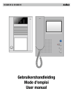
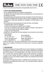
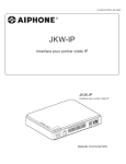
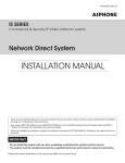
837405 A P0310 AQ 52150
JKW-IP
IP Video Intercom Adaptor
Interface pour portier vidéo IP
IP-Adapter für JK-Videotürsprechanlage
Adaptador de intercomunicación por vídeo IP
IP adapter voor JK videofonie
Adattatore interfono video IP
INSTALLATION MANUAL
MANUEL D’INSTALLATION
INSTALLATIONSANLEITUNG
MANUAL DE INSTALACIÓN
INSTALLATIEHANDLEIDING
MANUALE D'INSTALLAZIONE
NE
O
PH
AI
YB1
N
W
LA
JK
2 E
E S
S1
AC
T
A
ST
ER
W
S
PO
TU
-IP
IP
STR
GTH
RY R
4 E
E S
S3
B2
+ -
DC1
8V
OFF
N
ER O
POW
LAN
LEN
m
11m
∼
0.65
1.2
English
For safe and correct installation, be sure to read this installation manual carefully beforehand.
Also read the Operation manual on the accompanying CD-ROM.
ATTENTION
Be sure to provide the customer with the CD-ROM which accompanies the unit.
Français
ATTENTION
Deutsch
ACHTUNG
Español
ATENCIÓN
Nederlands
OPGELET
Italiano
AVVISO
Afin de garantir une installation conforme, veuillez prendre connaissance de ce manuel d’installation au préalable.
Veuillez également lire le manuel d’utilisation du CD-ROM qui accompagne chaque produit.
Veillez à donner au client le CD-ROM qui accompagne l’appareil.
Zur sicheren und korrekten Installation lesen Sie bitte diese Installationsanleitung sorgfältig durch.
Lesen Sie auch die Bedienungsanleitung auf der beiliegenden CD-ROM durch.
Stellen Sie sicher, dass die dem Gerät beiliegende CD-ROM dem Kunden geliefert wird.
Para una instalación correcta y segura, asegúrese de leer detenidamente este manual de instalación.
Lea también el manual de operación del CD-ROM de acompañamiento.
Asegúrese de proporcionar al cliente el CD-ROM que acompaña a la unidad.
Lees deze installatiehandleiding zorgvuldig op voorhand voor een veilige en correcte installatie.
Lees ook de gebruikshandleiding op de meegeleverde cd-rom.
Zorg ervoor dat u de klant steeds de cd-rom verschaft die bij het toestel geleverd wordt.
Per eseguire un'installazione corretta e sicura, leggere innanzitutto questo manuale d'installazione.
Leggere inoltre il Manuale d'uso contenuto nel CD-ROM in dotazione con ciascun prodotto.
Assicurarsi di fornire al cliente il CD-ROM in dotazione con l'unità.
English
PRECAUTIONS
Warning and Caution
General Prohibitions
Prohibition to
Dismantle the Unit
General Precautions
General Precautions
WARNING
English
Prohibition on Subjecting
the Unit to Water
Negligence could result in death or serious injury.
1. Keep the unit more than 1 m away from radio or TV set.
1. Do not dismantle or alter the unit. Fire or electric shock could
result.
2. Keep the intercom wires at least 30 cm (12") away from AC
100-240 V lines. Noise and malfunction could result.
2. Keep the unit away from water or any other liquid. Fire or
electric shock could result.
3. Install the unit in an area that will be accessible for future
inspections, repairs, and maintenance.
3. High voltage is present internally. Do not open the case.
Electric shock could result.
4. As to other manufacturer’s devices (such as sensor, detectors,
door releases) used with this system, comply with the
Specifications and Warranty conditions that the manufacturers
or venders present.
4. Do not connect any non-specified power source to the +, terminals. Also, do not install two power supplies in parallel to
a single input. Fire or damage to the unit could result.
5. This unit is for indoor use only. Do not use outdoors.
5. Do not connect any terminal on the unit to an AC power line.
Fire or electric shock could result.
6. If the unit is down or does not operate properly, unplug the
power supply or turn off the POWER switches.
6. Do not use power supply with a voltage other than specified.
Fire or electric shock could result.
7. When wall-mounted, the top of the unit may darken. This does
not indicate a malfunction.
7. Do not put any metal or flammable material into the unit
through the openings. Fire, electric shock, or unit trouble could
result.
8. The unit case may become warm with use, but this is not a unit
malfunction.
9. If it is used close to a cellular phone, the unit may malfunction.
10. The unit can be damaged if dropped. Handle with care.
CAUTION
11. The unit turns inoperative during power failure.
12. In areas where broadcasting station antennas are close by,
the intercom system may be affected by radio frequency
interference.
Negligence could result in injury to people or damage to
property.
1. Do not install or make any wire terminations while power
supply is plugged in. It can cause electrical shock or damage
to the unit.
2. When mounting the unit on a wall, install the unit in a
convenient location, but not where it could be jarred or
bumped. Injury could result.
3. Before turning on power, make sure wires are not crossed or
shorted. If not, fire or electric shock could result.
4. Do not install the unit in locations subject to frequent vibration
or impact. It may fall or tip over and possibly damage the unit.
5. For power supply, use Aiphone power supply model or model
specified for use with system. If non-specified product is used,
fire or malfunction could result.
6. Do not put anything on the unit or cover the unit with cloth,
etc. Fire or unit trouble could result.
7. Do not install the unit in any of the following locations. Fire,
electric shock, or unit trouble could result.
* Places under direct sunlight or places near heating
equipment that varies in temperature.
* Places subject to dust, oil, chemicals, etc.
* Places subject to moisture and humidity extremes, such as
bathrooms, cellars, greenhouses, etc.
* Places where the temperature is quite low, such as inside a
refrigerated area or in front of an air conditioner.
* Places subject to steam or smoke (near heating or cooking
surfaces).
* Where noise generating devices such as dimmer switches
or inverter electrical appliances are close by.
PACKAGE CONTENTS
JKW-IP
Wood mounting screws × 2
(ø4 × 16 mm)
“OPERATION MANUAL & Software” (CD-ROM) X 1
Installation Manual (this document)×1
Chinese ROHS (single sheet)×1
+ -
O
PH
AI
YB1
NE
N
LA
W
JK
PO
ER
W
US
AT
T
ST
AC
-IP
S1
E S2
E S3
E S4
B2
R ON
E RYR
8V
OFF
POWE
DC1
LAN
GTH
IP LEN
STR
m
11m
∼
0.65
1.2
Spacers × 2
NAMES
Default setting switch (within the sticker area)
Never press the default setting
switch unless it is necessary.
The registered settings will
return to the factory (default)
settings.
MADE IN JAPAN
MAC Address
(Do not remove)
O
PH
AI
YB1
NE
LA
W
JK
N
2 E
E S
S1
ER
W
US
PO
AT
T
AC
ST
-IP
TH
RY R
4 E
E S
S3
+ -
B2
8V
DC1
OFF
POWER switch
Turns the power ON or OFF.
ER ON
POW
POWER terminal (18V DC)
Connects the power cable.
LAN
ENG
IP L
STR
m
11 m
∼
0.65
1.2
Master monitor station connection terminal
Connects to the master monitor station.
Option output terminal
Connects output signals for option unit.
Sensor input 1~4 terminals
Connects to buttons, sensors, etc. for option unit.
LAN port
Connects networking unit such as router.
LAN ACT indicator (Orange)
Lit orange when a LAN is connected, and blinks while exchanging information over the Ethernet.
STATUS indicator (Orange)
Blinks orange while the system starts up, and remains lit once startup is complete.
POWER indicator (Green)
Lit green when the power is on.
WIRING DISTANCE
A
JK-DA
JK-DV
JK-DVF
D
JK-1MED or JK-1MD
2
JKW-IP
2
+ -
HO
NE
N
W
LA
JK
W
S1
S
PO
ATU
T
-IP
ST
AC
ER
PS18
2
P
AI
2
IP LEN
STR
GTH
m
11m
0.65∼
E S2
E S3
E S4
RY
E RY
LAN
1.2
PS-1820
B
A
B
C
D
Ø0.65 mm
50 m
5m
50 m
–
22AWG
165'
16'
165'
–
Ø1.0 mm
100 m
10 m
100 m
–
C
18AWG
330'
33'
330'
–
CAT5e/6
–
–
–
100 m, 330'
B1 B2
R ON
DC18V
OFF
POWE
Router
English
< Back view >
CABLE
1
English
2
Use PVC jacket with PE
(polyethylene) insulated cable.
When using a cable with unused
conductors, terminate both ends
of the unused pair(s) with a 120 Ω
resistor.
3
(×2)
Never use individual conductors,
twisted pair cable or coaxial
cable.
(Excess wires)
120Ω
120Ω
B1
B1
B2
IP video intercom
adaptor
B2
Master
station
Odd number cables, such as
three conductor wire, cannot be
used.
4
●About LAN cables
●W
hen installing LAN cables, do not bend them to an extent where the radius is 30 mm (1-3/16”) or less.
Communication failure could result.
LAN cable
LAN cable
Radius<30 mm (1-3/16”)
Radius≧30 mm (1-3/16”)
Pair3
Pair2
●D
o not remove more of the LAN cable jacket than necessary.
● Arrange the color code of the RJ45 connections in accordance with EIA/TIA568A and 568B.
Pair2 Pair1 Pair4
Pair1 Pair4
Pair3
12345678
12345678
T568A
T568B
MOUNTING
Install the unit on a shelf or wall in an area that will be accessible for future inspections, repairs, and
maintenance.
Be sure to install the unit so that each indicator can be checked.
● When installing the unit on the wall
1
Attach spacers to the wood mounting
screws, and then attach them to the
wall.
Unit
Size of the gap between the screws
for installing the unit on the wall
POWER
90 mm (3-17/32”)
STATUS
2
Attach the unit.
30 mm (1-3/16”)
or more
LAN ACT
N
IN JAPA
90 mm (3-17/32”)
・
・
・ ・
・
・
・ ・・
・
・
・
・ ・・
・
・ ・ ・ Spacers
・
・ ・
・
・
×2
・ ・・・ ・ ・
・
Wood mounting
screws × 2
AIPHONE JKW-IP
MADE
Object
When installing the unit on
the wall, allow at least 30 mm
(1/3/16”) of open space between
the unit and any objects in the
vicinity.
WIRING
• Do not use the unmarked terminals for other purposes.
• For the connection of products manufactured by other
companies, refer to the manuals which accompany
them.
+ -
P
AI
NE
HO
YB1
LA
N
T
US
AT
ST
R
WE
PO
AC
-IP
W
JK
S1
TH
STRIP
E S2
E S3
E S4
B2
E RYR
V
OFF
POWER
ON
DC18
LAN
LENG
11mm
0.65∼
1.2
IP video intercom adaptor
JKW-IP
Switch (HUB)
To router
Cat5e/6
LAN
S1
E
*1. Input specifications
Input method
Detection
confirmation time
Contact resistance
2C
Option unit *1
During N/O dry closure: Less than 700 Ω
During N/C dry closure: At least 3 k Ω
Terminal short current Less than 10 mA
NP
2C
Sensor
input 2
Sensor
input 3
S2
E
S3
Voltage between
terminals
Option unit *1
Output method
Voltage between
terminals
2C
Option unit *1
E
S4
Less than 20 V DC(when open between
terminals)
*2. Output specifications
NP
NP
Sensor
input 4
N/O or N/C dry closure contact (start
signal only detection method)
100 mS or more
N/O dry closure contact
24V AC, 0.5A (resistive load)
24V DC, 0.5A (resistive load)
Minimum overload: 100mV DC, 0.1mA
PS-1820
2C
Option unit *1
E
NP
Option
output
RY
2C
100V - 240V- 50/60 Hz
Option unit *2
RY
NP
B1
2C
B1
B2
B2
● Connection of stranded wires
Twist the strands together, then insert the
wire into one of the quick coupling terminals.
JK master
monitor station
NP
DC18V
+
-
2C
P
+
-
18V DC 2A
11 mm
(7/16”)
Power supply
NP: Non-polarized
P : Polarized
Release button
Recommended wire
diameter: 1.0 mm (18AWG)
To ensure that the wire won't bend, press
the release button while inserting into
terminal.
SETTING UP
First, install the supplied software onto your PC in order to set up and use this unit.
Follow the operation manual located in each language folder of the accompanying CD-ROM to install and
set up the software.
OPERATION MANUAL &
Software (CD-ROM)
de : German
en : English
es : Spanish
fr : French
it : Italian
jp : Japanese
nl : Dutch
English
Sensor
input 1
Straight-through cable
English
Français
Deutsch
Español
Nederlands
Italiano
■This document has been carefully compiled. Should you have questions, find an error, or find that information is
missing, please contact your distributor or the nearest regional office.
The above provisions notwithstanding, we will under no conditions be liable for any damages or losses resulting
from use of this product.
■If you use this product for applications that require extreme reliability, please take thorough and appropriate
measures to ensure the safety of the intended system and to safeguard against possible failures.
■Specifications, design, and other aspects of the product indicated in this document are subject to change without
notice to allow for improvements.
■The names of products of other firms referenced in this document are the trademarks or registered trademarks of
the respective companies.
Such product names are not explicitly indicated by the symbols “TM”, “®”, or “©”.
■Ce document a été établi avec attention. Pour toute question, en cas d’erreur ou d’information manquante,
veuillez contactez votre distributeur ou le bureau régional le plus proche.
A l’exception des mentions précédentes, nous ne serons en aucune circonstance responsables des dommages
ou pertes causées par l’utilisation de ce produit.
■Si vous utilisez ce produit pour des applications nécessitant une très grande fiabilité, veuillez prendre toutes les
mesures appropriées afin de garantir la sécurité du système envisagé et de vous prémunir contre les pannes
possibles.
■Les spécifications, la conception et les autres aspects du produit mentionnés dans ce document sont susceptibles
d’être modifiés sans préavis, afin d’en permettre l’amélioration.
■Les noms des produits d’autres sociétés mentionnés dans le présent document sont les marques ou les marques
déposées de ces mêmes sociétés.
Les noms de ces produits ne sont pas explicitement désignés par les symboles « TM », « R » ou « C ».
■Dieses Dokument wurde mit Sorgfalt erstellt. Wenn Sie Fragen haben, einen Fehler finden oder Ihrer Meinung
nach Informationen fehlen, wenden Sie sich bitte an Ihren Händler oder die nächste regionale AIPHONEVertretung.
Ungeachtet der obenstehenden Angaben haften wir für keinerlei Schäden oder Verluste, die aufgrund des
Gebrauchs dieses Produkts entstehen.
■Bei Gebrauch dieses Produkts für Anwendungen, die extreme Sicherheit erfordern, ergreifen Sie bitte sorgfältige
und angemessene Maßnahmen, um die Sicherheit des vorgesehenen Systems zu gewährleisten und gegen
mögliche Störungen zu schützen.
■Technische Daten, Design und andere Aspekte des Produkts, die in diesem Dokument dargestellt werden, können
jederzeit ohne Ankündigung zum Zwecke der Verbesserung geändert werden.
■Die Namen von Produkten anderer Hersteller, die in diesem Dokument genannt werden, sind Warenzeichen oder
eingetragene Warenzeichen der jeweiligen Unternehmen.
Derartige Produktnamen werden nicht ausdrücklich mit den Symbolen "TM", "R" oder "C" versehen.
26
AIPHONE CO., LTD., NAGOYA, JAPAN
AIPHONE CORPORATION, BELLEVUE, WA, USA
AIPHONE S.A.S., LISSES-EVRY, FRANCE
http://www.aiphone.net/
Printed in Japan