1
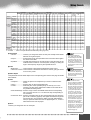
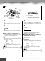
Make sure that your local AC mains
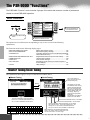
voltage matches the voltage specified
on the name plate on the bottom panel.
In some areas a voltage selector may
be provided on the rear panel of the
PSR-9000 near the power cord. Make
sure that the voltage selector is set for
the voltage in your area. The voltage
selector is set at 240V when the unit is
initially shipped.
To change the setting use a slotted
("minus") screwdriver to rotate the
selector dial so that the correct voltage
appears next to the pointer on the
panel.
Stellen Sie sicher, daß Ihre
Netzstromversorgung mit der auf dem
Etikett auf der Unterseite
übereinstimmt. In manchen Fällen ist
ein Spannungswähler an der Rückseite
des PSR-9000 in der Nähe des
Netzkabels installiert. Beachten Sie,
daß der Spannungswähler auf die
Spannung für Ihren Wohnort eingestellt
ist. Der Spannungswähler wird vom
Hersteller auf 240V eingestellt.
Verwenden Sie zum Ändern der
Einstellung einen
Schlitzschraubendreher, um die
Wählscheibe so zu drehen, daß die
korrekte Spannung unter der
Markierung auf der Abdeckung
angezeigt wird.
Vérifiez que la tension de votre
alimentation secteur correspond à celle
qui est spécifiée sur la plaque du
fabricant, située sur le panneau du bas.
Dans certaines régions, l'instrument
peut disposer d'un sélecteur de tension
installé sur son panneau arrière, près
du cordon d'alimentation. Assurez-vous
que le sélecteur de tension est réglé
sur la valeur en vigueur dans votre
région. Au départ de l'usine, le
sélecteur de tension de l'unité est
initialement spécifié sur 240V.
Pour modifier ce réglage, utilisez un
tournevis pour écrous à fente et faites
tourner le cadran du sélecteur jusqu'à
ce que la valeur correcte s'affiche en
marge de l'indicateur sur le panneau.
SPECIAL MESSAGE SECTION
See bottom of Keyboard enclosure for graphic symbol markings.
The exclamation point within the equilateral triangle is intended to alert the
user to the presence of important operating and maintenance (servicing) instructions in the literature accompanying the
product.
The lightning flash with arrowhead symbol, within the equilateral triangle, is
intended to alert the user to the presence
of uninsulated “dangerous voltage”
within the product’s enclosure that may
be of sufficient magnitude to constitute a
risk of electrical shock.
IMPORTANT NOTICE: All Yamaha electronic products
are tested and approved by an independent safety testing
laboratory in order that you may be sure that when it is properly installed and used in its normal and customary manner,
all foreseeable risks have been eliminated. DO NOT modify
this unit or commission others to do so unless specifically
authorized by Yamaha. Product performance and/or safety
standards may be diminished. Claims filed under the
expressed warranty may be denied if the unit is/has been
modified. Implied warranties may also be affected.
SPECIFICATIONS SUBJECT TO CHANGE: The information contained in this manual is believed to be correct at
the time of printing. However, Yamaha reserves the right to
change or modify any of the specifications without notice or
obligation to update existing units.
Warning: Do not attempt to recharge, disassemble, or incinerate this type of battery. Keep all batteries away from children. Dispose of used batteries promptly and as regulated by
applicable laws. Note: In some areas, the servicer is required
by law to return the defective parts. However, you do have
the option of having the servicer dispose of these parts for
you.
Disposal Notice: Should this product become damaged
beyond repair, or for some reason its useful life is considered to be at an end, please observe all local, state, and federal regulations that relate to the disposal of products that
contain lead, batteries, plastics, etc.
NOTICE: Service charges incurred due to lack of knowledge relating to how a function or effect works (when the
unit is operating as designed) are not covered by the manufacturer’s warranty, and are therefore the owners responsibility. Please study this manual carefully and consult your
dealer before requesting service.
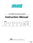
NAME PLATE LOCATION: The graphic below indicates
the location of the name plate. The model number, serial
number, power requirements, etc., are located on this plate.
You should record the model number, serial number, and the
date of purchase in the spaces provided below and retain this
manual as a permanent record of your purchase.
MIDI A
IN
PC KEYBOARD
AC INLET
MIDI B
OUT
IN
OUT
FOOT PEDAL
SWITCH 1
SWITCH 2
VOLUME
HOST SELECT TO HOST
PC-2
MIDI
VIDEO OUT
SCSI
CAUTION
RISK OF ELECTRIC SHOCK
DO NOT OPEN
PC-1
Mac
AVIS : RISQUE DE CHOC ÉLECTRIQUE–NE PAS OUVRIR.
WARNING :
240V
LINE OUT
2
1
R
L/L+R
TO REDUCE THE RISK OF FIRE OR ELECTRIC SHOCK,
DO NOT EXPOSE THIS PRODUCT TO RAIN OR MOISTURE.
MIDI A
NTSC/PAL
AUX IN/ LOOP RETURN
TRIM
R
L/L+R
LOOP SEND
R
L/L+R
220V
CAUTION: TO REDUCE THE RISK OF ELECTRIC SHOCK.
DO NOT REMOVE COVER (OR BACK).
NO USER-SERVICEABLE PARTS INSIDE.
REFER SERVICING TO QUALIFIED SERVICE PERSONNEL.
Battery Notice: This product MAY contain a small nonrechargable battery which (if applicable) is soldered in
place. The average life span of this type of battery is approximately five years. When replacement becomes necessary,
contact a qualified service representative to perform the
replacement.
130
V
CAUTION
RISK OF ELECTRIC SHOCK
DO NOT OPEN
ENVIRONMENTAL ISSUES: Yamaha strives to produce
products that are both user safe and environmentally
friendly. We sincerely believe that our products and the production methods used to produce them, meet these goals. In
keeping with both the letter and the spirit of the law, we
want you to be aware of the following:
V
110
PRODUCT SAFETY MARKINGS: Yamaha electronic
products may have either labels similar to the graphics
shown below or molded/stamped facsimiles of these graphics on the enclosure. The explanation of these graphics
appears on this page. Please observe all cautions indicated
on this page and those indicated in the safety instruction section.
MIN
SUB
MAX
MAIN
Model
Serial No.
Purchase Date
92-469- ➀ (bottom)
2
●●●●●●●●●●●●●●●●●●●●●●●●●●●●●●●●●●●●●●●●●●●●●●●●
IMPORTANT SAFETY INSTRUCTIONS
INFORMATION RELATING TO PERSONAL INJURY, ELECTRICAL SHOCK,
AND FIRE HAZARD POSSIBILITIES HAS BEEN INCLUDED IN THIS LIST.
WARNING- When using any electrical or electronic product,
basic precautions should always be followed. These precautions
include, but are not limited to, the following:
1.
Read all Safety Instructions, Installation Instructions, Special Message Section items, and any Assembly Instructions found
in this manual BEFORE making any connections, including connection to the main supply.
2.
Main Power Supply Verification: Yamaha products are
manufactured specifically for the supply voltage in the area where
they are to be sold. If you should move, or if any doubt exists about
the supply voltage in your area, please contact your dealer for supply voltage verification and (if applicable) instructions. The
required supply voltage is printed on the name plate. For name
plate location, please refer to the graphic found in the Special Message Section of this manual.
3.
This product may be equipped with a polarized plug (one
blade wider than the other). If you are unable to insert the plug into
the outlet, turn the plug over and try again. If the problem persists,
contact an electrician to have the obsolete outlet replaced. Do NOT
defeat the safety purpose of the plug.
4.
Some electronic products utilize external power supplies or
adapters. Do NOT connect this type of product to any power supply or adapter other than one described in the owners manual, on
the name plate, or specifically recommended by Yamaha.
5.
WARNING: Do not place this product or any other objects
on the power cord or place it in a position where anyone could
walk on, trip over, or roll anything over power or connecting cords
of any kind. The use of an extension cord is not recommended! If
you must use an extension cord, the minimum wire size for a 25’
cord (or less) is 18 AWG. NOTE: The smaller the AWG number,
the larger the current handling capacity. For longer extension
cords, consult a local electrician.
6.
Ventilation: Electronic products, unless specifically
designed for enclosed installations, should be placed in locations
that do not interfere with proper ventilation. If instructions for
enclosed installations are not provided, it must be assumed that
unobstructed ventilation is required.
7.
8.
This product was NOT designed for use in wet/damp locations and should not be used near water or exposed to rain. Examples of wet/damp locations are; near a swimming pool, spa, tub,
sink, or wet basement.
9.
This product should be used only with the components
supplied or; a cart, rack, or stand that is recommended by the manufacturer. If a cart, rack, or stand is used, please observe all safety
markings and instructions that accompany the accessory product.
10.
The power supply cord (plug) should be disconnected from
the outlet when electronic products are to be left unused for
extended periods of time. Cords should also be disconnected when
there is a high probability of lightening and/or electrical storm
activity.
11.
Care should be taken that objects do not fall and liquids are
not spilled into the enclosure through any openings that may exist.
12.
Electrical/electronic products should be serviced by a qualified service person when:
a. The power supply cord has been damaged; or
b. Objects have fallen, been inserted, or liquids have been
spilled into the enclosure through openings; or
c. The product has been exposed to rain: or
d. The product dose not operate, exhibits a marked change
in performance; or
e. The product has been dropped, or the enclosure of the
product has been damaged.
13.
Do not attempt to service this product beyond that
described in the user-maintenance instructions. All other servicing
should be referred to qualified service personnel.
14.
This product, either alone or in combination with an amplifier and headphones or speaker/s, may be capable of producing
sound levels that could cause permanent hearing loss. DO NOT
operate for a long period of time at a high volume level or at a level
that is uncomfortable. If you experience any hearing loss or ringing
in the ears, you should consult an audiologist.
IMPORTANT: The louder the sound, the shorter the time period
before damage occurs.
15.
Temperature considerations: Electronic products should be
installed in locations that do not significantly contribute to their
operating temperature. Placement of this product close to heat
sources such as; radiators, heat registers and other devices that produce heat should be avoided.
Some Yamaha products may have benches and/or accessory mounting fixtures that are either supplied as a part of the product or as optional accessories. Some of these items are designed to
be dealer assembled or installed. Please make sure that benches are
stable and any optional fixtures (where applicable) are well secured
BEFORE using. Benches supplied by Yamaha are designed for
seating only. No other uses are recommended.
PLEASE KEEP THIS MANUAL
92-469-2
1
●●●●●●●●●●●●●●●●●●●●●●●●●●●●●●●●●●●●●●●●●●●●●●●●●
3
PRECAUTIONS
PLEASE READ CAREFULLY BEFORE PROCEEDING
* Please keep these precautions in a safe place for future reference.
WARNING
Always follow the basic precautions listed below to avoid the possibility of serious injury or even death from electrical shock,
short-circuiting, damages, fire or other hazards. These precautions include, but are not limited to, the following:
• Do not open the instrument or attempt to disassemble the internal parts or
modify them in any way. The instrument contains no user-serviceable
parts. If it should appear to be malfunctioning, discontinue use immediately and have it inspected by qualified Yamaha service personnel.
• Do not expose the instrument to rain, use it near water or in damp or wet
conditions, or place containers on it containing liquids which might spill
into any openings.
• If the power cord or plug becomes frayed or damaged, or if there is a sudden loss of sound during use of the instrument, or if any unusual smells or
smoke should appear to be caused by it, immediately turn off the power
switch, disconnect the electric plug from the outlet, and have the instrument inspected by qualified Yamaha service personnel.
• Only use the voltage specified as correct for the instrument. The required
voltage is printed on the name plate of the instrument.
• Before cleaning the instrument, always remove the electric plug from the
outlet. Never insert or remove an electric plug with wet hands.
• Check the electric plug periodically and remove any dirt or dust which may
have accumulated on it.
CAUTION
Always follow the basic precautions listed below to avoid the possibility of physical injury to you or others, or damage to the
instrument or other property. These precautions include, but are not limited to, the following:
• Do not place the power cord near heat sources such as heaters or radiators, and do not excessively bend or otherwise damage the cord, place
heavy objects on it, or place it in a position where anyone could walk on,
trip over, or roll anything over it.
• Use only the stand/rack specified for the instrument. When attaching the
stand or rack, use the provided screws only. Failure to do so could cause
damage to the internal components or result in the instrument falling over.
• When removing the electric plug from the instrument or an outlet, always
hold the plug itself and not the cord. Pulling by the cord can damage it.
• Do not place objects in front of the instrument’s air vent, since this may
prevent adequate ventilation of the internal components, and possibly
result in the instrument overheating.
• Do not connect the instrument to an electrical outlet using a multiple-connector. Doing so can result in lower sound quality, or possibly cause overheating in the outlet.
• Do not operate the instrument for a long period of time at a high or uncomfortable volume level, since this can cause permanent hearing loss. If you
experience any hearing loss or ringing in the ears, consult a physician.
• Remove the electric plug from the outlet when the instrument is not to be
used for extended periods of time, or during electrical storms.
• Before connecting the instrument to other electronic components, turn off
the power for all components. Before turning the power on or off for all
components, set all volume levels to minimum. Also, be sure to set the
volumes of all components at their minimum levels and gradually raise the
volume controls while playing the instrument to set the desired listening
level.
• Do not expose the instrument to excessive dust or vibrations, or extreme
cold or heat (such as in direct sunlight, near a heater, or in a car during the
day) to prevent the possibility of panel disfiguration or damage to the internal components.
• Do not use the instrument near other electrical products such as televisions, radios, or speakers, since this might cause interference which can
affect proper operation of the other products.
• Do not place the instrument in an unstable position where it might accidentally fall over.
• Before moving the instrument, remove all connected cables.
• When cleaning the instrument, use a soft, dry cloth. Do not use paint thinners, solvents, cleaning fluids, or chemical-impregnated wiping cloths.
Also, do not place vinyl, plastic or rubber objects on the instrument, since
this might discolor the panel or keyboard.
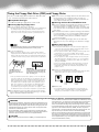
■BACKING UP THE FACTORY DATA
Storing your original data to Flash ROM erases the corresponding factory
data programmed to the Flash ROM (at the corresponding number locations).
The following data types are affected:
• One Touch Setting
• Registration Memory
• Music Database
• Multi Pad
• Flash Style
• Setup
If you've deleted the factory-set data, you can use the Restore function (page
98) to load a copy of it from the included disks (page 6).
■SAVING USER DATA
• Always save data to a floppy disk frequently, in order to help prevent the
loss of important data due to a malfunction or user operating error.
Yamaha cannot be held responsible for damage caused by improper use
or modifications to the instrument, or data that is lost or destroyed.
Always turn the power off when the instrument is not in use.
• Do not rest your weight on, or place heavy objects on the instrument, and
do not use excessive force on the buttons, switches or connectors.
(1)-5
4
●●●●●●●●●●●●●●●●●●●●●●●●●●●●●●●●●●●●●●●●●●●●●●●●
2
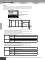
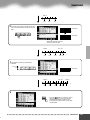
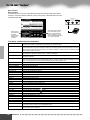
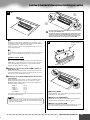
Using the Floppy Disk Drive (FDD) and Floppy Disks
■ Compatible Disk Type
● Be sure to remove the floppy disk from the disk drive before
turning off the power. A floppy disk left in the drive for
extended periods can easily pick up dust and dirt that can
cause data read and write errors.
3.5" 2DD and 2HD type floppy disks can be used.
■ Cleaning the Disk Drive Read/Write Head
■ Inserting/Ejecting Floppy Disks
● Clean the read/write head regularly. This instrument employs
a precision magnetic read/write head which, after an
extended period of use, will pick up a layer of magnetic particles from the disks used that will eventually cause read and
write errors.
● To maintain the disk drive in optimum working order Yamaha
recommends that you use a commercially-available dry-type
head cleaning disk to clean the head about once a month.
Ask your Yamaha dealer about the availability of proper
head-cleaning disks.
● Never insert anything but floppy disks into the disk drive.
Other objects may cause damage to the disk drive or floppy
disks.
Be sure to handle floppy disks and treat the disk drive with
care. Follow the important precautions below.
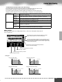
● To insert a floppy disk into the disk drive:
• Hold the disk so that the label of the disk is facing upward and
the sliding shutter is facing forward, towards the disk slot.
Carefully insert the disk into the slot, slowly pushing it all the
way in until it clicks into place and the eject button pops out.
■ About the Floppy Disks
• When the PSR-9000 is turned on, the LED below the floppy disk
slot will be lit indicating that the Disk Drive is ready to use.
● To eject a floppy disk:
• Before ejecting the disk, be sure to confirm that the FDD is
stopped (check if the DISK IN USE lamp is off). Press the eject
button slowly as far as it will go; the disk will automatically pop
out. When the disk is fully ejected, carefully remove it by hand.
DISK IN USE
This lamp is always on
when the power is on,
regardless of the disk operation.
DISK IN USE
This lamp lights during disk read/write
operations, such as when a disk has
been inserted, during recording, playback, formatting, etc.
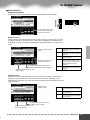
• If the eject button is pressed too quickly, or if it is not pressed
in as far as it will go, the disk may not eject properly. The eject
button may become stuck in a half-pressed position with the
disk extending from the drive slot by only a few millimeters. If
this happens, do not attempt to pull out the partially ejected
disk, since using force in this situation can damage the disk
drive mechanism or the floppy disk. To remove a partially
ejected disk, try pressing the eject button once again, or push
the disk back into the slot and then repeat the eject procedure.
● Never attempt to remove the disk or turn the power off during recording, reading and playing back. Doing so can damage the disk and possibly the disk drive.
● To handle floppy disks with care:
• Do not place heavy objects on a disk or bend or apply pressure to the disk in any way. Always keep floppy disks in their
protective cases when they are not in use.
• Do not expose the disk to direct sunlight, extremely high or low
temperatures, or excessive humidity, dust or liquids.
• Do not open the sliding shutter and touch the exposed surface
of the floppy disk inside.
• Do not expose the disk to magnetic fields, such as those produced by televisions, speakers, motors, etc., since magnetic
fields can partially or completely erase data on the disk, rendering it unreadable.
• Never use a floppy disk with a deformed shutter or housing.
• Do not attach anything other than the provided labels to a
floppy disk. Also make sure that labels are attached in the
proper location.
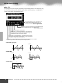
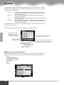
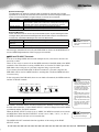
● To protect your data (write-protect tab):
• To prevent accidental erasure of important data, slide the disk’s
write-protect tab to the “protect” position (tab open).
Write protect tab ON
(locked or write protected)
Write protect tab OFF
(unlocked or write
enabled)
● Data backup
• For maximum data security Yamaha recommends that you
keep two copies of important data on separate floppy disks.
This gives you a backup if one disk is lost or damaged.
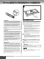
Handling and Installation of Options
WARNING
• Before beginning installation, switch off the power to the PSR-9000 and connected peripherals, and unplug them from the power outlet. Then remove all
cables connecting the PSR-9000 to other devices. (Leaving the power cord
connected while working can result in electric shock. Leaving other cables
connected can interfere with work.)
• Do not disassemble, modify, or apply excessive force to board areas and
connectors on hard disk, and SIMMs. Bending or tampering with boards and
connectors may lead to electric shock, fire, or equipment failures.
CAUTION
• Before handling the internal hard disk or SIMMs, you should briefly touch
the metal surface to which the hard-disk or SIMM cover is attached (or other
such metallic area — be careful of any sharp edges) with your bare hand so
as to drain off any static charge from your body. Note that even a slight
amount of electrostatic discharge may cause damage to these components.
• It is recommended that you wear gloves to protect your hands from metallic
projections on the PSR-9000 hard disk, SIMMs, and other components.
Touching leads or connectors with bare hands may cause finger cuts, and
may also result in poor electrical contact or electrostatic damage.
• Take care to avoid dropping screws into the PSR-9000 unit. If a screw does
fall in, be sure to remove it before replacing the cover and powering up the
unit. Starting the unit with a loose screw inside may lead to improper operation or equipment failure. (If you are unable to retrieve a dropped screw, consult your Yamaha dealer for advice.)
3
●●●●●●●●●●●●●●●●●●●●●●●●●●●●●●●●●●●●●●●●●●●●●●●●●
5
Congratulations!
You are the proud owner of an extraordinary electronic keyboard. The Yamaha PSR-9000 combines the
most advanced tone generation technology with state-of-the-art digital electronics and features to give
you stunning sound quality with maximum musical versatility. The advanced Auto Accompaniment, Vocal
Harmony, and Sampler features, in particular, are brilliant examples of how Yamaha technology can significantly expand your musical horizons. A large-size graphic display and easy-to-use interface also greatly
enhance the operability of this advanced instrument.
In order to make the most of your PSR-9000’s features and vast performance potential, we urge you to
read the manual thoroughly while trying out the various features described. Keep the manual in a safe
place for later reference.
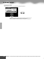
Packing List
Your PSR-9000 includes the following items:
• PSR-9000 x 1
• AC Power Cord x 1
• AC Plug Adaptor x 1 (in applicable areas only)
• Music Stand x 1
• Floppy Disk x 1 (includes accompaniment style files: page 25)
• Floppy Disks x 2
(These include the following factory-set data: One Touch Setting, Registration
Memory, Music Database, Multi Pad, Flash Style and Setup.)
• Owner’s Manual
Unauthorized copying of copyrighted software for purposes other than the purchaser’s personal use is prohibited.
This product (PSR-9000) is manufactured under license of U.S.Patents No.5231671, No.5301259,
No.5428708, and No.5567901 of IVL Technologies Ltd.
Trademarks:
• Apple and Macintosh are trademarks of Apple Computer, Inc., registered in the U.S. and other countries.
• IBM-PC/AT is a trademark of International Business MachinesCorporation.
• Windows is the registered trademark of Microsoft ® Corporation.
• All other trademarks are the property of their respective holders.
6
●●●●●●●●●●●●●●●●●●●●●●●●●●●●●●●●●●●●●●●●●●●●●●●●
4
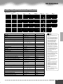
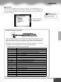
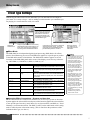
New Functions in PSR-9000 Version 2
The following features have been newly added as part of the upgrade to PSR-9000 Version 2.0.
• Vocal Harmony
An added note of polyphony (for a total of three Vocal Harmony
notes), and more Vocal Harmony types, including Quartet.
• Sampling
Key Mapping, Resampling, Loop Point editing, Normalize, and
an Export WAV function for using PSR-9000 samples in the
common WAV format.
• Custom Voice
Full Parameter editing, and editing of individual voice elements.
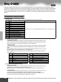
• Song Creator
Step Recording, Event editing, Chord Step Recording, Quantize and other editing functions.
• Style Creator
• Multi Pad Creator
Step Recording and Event editing.
• Disk/SCSI
Song file rename function for SMF songs and User songs from
the PSR-8000, and a directory rename for the PSR-8000 hard
disk.
• Song Player
Ability to show song list and select song while playing.
• Registration Memory
Enhanced compatibility with Custom Styles from the PSR-8000
• Organ Flute 9 Footages
Control over nine Footages, plus new tone generation system
and new sampled waves.
Realtime Recording, Step Recording, Event editing, and Full
Parameter editing.
How to use the manual
Starting Up........................................................................................................................page 14
Before going on to any other part of the manual, we strongly suggest you read this section first. It shows you
how to get started playing and using your new PSR-9000.
Top Panel & Connections................................................................................................page 10
Rear Panel & Connections ..............................................................................................page 12
Use this section to find out about all of the buttons and controls of the PSR-9000.
Contents .............................................................................................................................page 8
All topics, features, functions, and operations are listed here in the order they appear in the manual, for easy
reference.
Quick Guide ......................................................................................................................page 16
Unless you enjoy reading manuals, you’re probably eager to start playing your new PSR-9000 right now. If so,
read this section.
Basic Operations .............................................................................................................page 42
This section introduces you to the basic operating conventions of the PSR-9000, such as editing values and
changing settings, and shows you how to use the convenient Direct Access functions.
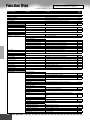
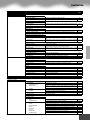
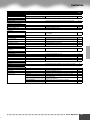
Function Tree....................................................................................................................page 46
This lists all functions of the PSR-9000 according to their hierarchical structure, letting you easily see the relationship of the various functions and quickly locate desired information.
Reference..........................................................................................................................page 52
Once you’re familiar with everything above, lightly go over this comprehensive guide to all functions. You won’t
need (or want) to read everything at once, but it is there for you to refer to when you need information about a
certain feature or function.
Appendix.........................................................................................................................page 156
This contains various important lists such as the Voice List, Preset Style List, Effect List, MIDI Data Format,
and MIDI Implementation Chart.
Troubleshooting .............................................................................................................page 156
If the PSR-9000 does not function as expected or you have some problem with the sound or operation, consult
this section before calling your Yamaha dealer or service center. Most common problems and their solutions
are covered here in a very simple and easy-to-understand way.
Index................................................................................................................................page 158
This section alphabetically lists virtually all topics, features, functions, and operations with their respective
page numbers, letting you quickly and easily find the information you need.
5
●●●●●●●●●●●●●●●●●●●●●●●●●●●●●●●●●●●●●●●●●●●●●●●●●
7
Contents
Page Numbers marked with * have been added as part of the upgrade to PSR-9000 Version 2.
Packing List .................................................6
New Functions in PSR-9000 Version 2 .......7
How to use the manual ............................... 7
Contents ..............................................................8
Top Panel & Connections.................................. 10
Rear Panel & Connections................................ 12
Starting Up ........................................................14
Music stand ...............................................15
Panel logos ...............................................15
Basic Operation
Display-based Controls .............................. 42
Display Messages ............................................ 43
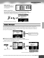
Name Entry ...................................................... 44
Computer Keyboard Functions ......................... 44
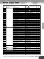
Direct Access Chart ................................... 45
Function Tree ............................................... 46
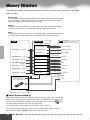
Memory Structure ....................................... 50
Quick Guide
Reference
Playing Voices ............................................. 16
Demonstration ............................................ 52
Playing a Voice ..................................................16
Playing Two or Three Voices Simultaneously ....17
Playing Different Voices
with the Left and Right Hands ..............18
Adjusting the Octave setting .............................18
Organ Flutes .....................................................19
Voices .......................................................... 53
Auto Accompaniment ................................. 20
Organ Flutes ................................................ 56
Using Auto Accompaniment ..............................20
Accompaniment Sections .................................22
One Touch Setting .............................................24
Track Muting & Volume Control .........................24
Disk Direct Function ..........................................25
Music Database ........................................... 26
Using the Music Database ................................26
Searching the Music Database .........................27
Parts: Right1, Right2, Right3 and Left .............. 53
Voices ............................................................... 54
PITCH BEND Wheel & MODULATION Wheel ... 54
Voice Effects ..................................................... 55
Other Keyboard-related Functions ................... 55
Auto Accompaniment ................................. 58
Chord Fingerings .............................................. 58
Fade-ins and Fade-outs ................................... 60
Tempo Control .................................................. 60
Synchro Stop .................................................... 61
One Touch Setting ............................................ 61
Style Manager .................................................. 62
Music Database .......................................... 64
Registration Memory .................................. 28
Creating the Music Database ........................... 64
Using the Preset Registration Memory .............28
Registering the Panel Settings ..........................29
The Multi Pads ............................................ 65
Disk Song Playback .................................... 30
Playback of Song Disks ....................................30
Vocal Harmony ............................................ 32
Setting Up .........................................................32
Vocal Harmony with Accompaniment Playback ..32
Vocal Harmony with Song Playback .................33
The Multi Pads ............................................. 34
Turning Chord Match and Repeat On/Off ......... 65
Disk Song Playback .................................... 66
Selecting a Song .............................................. 66
Other Functions: Viewing the Lyrics
and Fast Forward/Reverse .................. 67
Song Setup ...................................................... 67
Vocal Harmony ............................................ 68
Voice Effects ................................................ 35
Applying the Vocal Harmony Effect .................. 68
Selecting/Producing the Vocal Harmony effect .. 69
Changing the Vocal Harmony/
Microphone Settings ........................... 70
Applying the Voice Effects .................................35
Sampling ..................................................... 72
Playing the Multi Pads .......................................34
Chord Match .....................................................34
Song Creator ............................................... 36
Quick Recording ................................................36
Multi Track Recording ........................................38
Sampling ...................................................... 40
Recording a Sample .........................................40
Recording a Sample ......................................... 74
Importing Wave Files from Disk ....................... 75
Clearing Wave Data ......................................... 75
Editing Wave data ............................................ 76 *
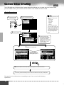
Custom Voice Creating ............................... 80
Easy Editing ..................................................... 81
Full Editing ....................................................... 82 *
8
●●●●●●●●●●●●●●●●●●●●●●●●●●●●●●●●●●●●●●●●●●●●●●●●
6
Contents
Song Creator ............................................... 88
Track Setting for Recording
(Multi Track Recording) ........................90
Track Setting for Recording
(Quick Recording) ................................91
Song Edit Functions (Multi Track Recording) ....92 *
Song Setup (Multi Track Recording) ..................93
Step Recording (Multi Track Recording) ............94 *
Chord Step (Quick Recording) ........................100 *
Style Creator ............................................. 104
Style Assembly — Creating a Style ................107
Revoice (Easy Edit) .........................................108
Groove & Dynamics (Easy Edit) ......................109
Style Recording (Full Edit) ..............................110 *
Style Editing (Full Edit) ....................................112 *
Custom Style Recording
via an External Sequence Recorder ..116 *
Step Recording (Full Edit) ...............................118 *
Multi Pad Creator ...................................... 119
Multi Pad Recording ........................................120
Clear ...............................................................120
Copy ................................................................120
Turning Chord Match and Repeat On/Off .......120
Step Recording ...............................................121 *
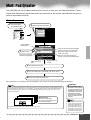
Mixing Console ......................................... 122
Part Settings ...................................................122
Effect Type Settings .........................................124
Master Equalizer Settings ...............................125
Line Out Settings ............................................126
MIDI Functions .......................................... 144
What’s MIDI? .................................................. 144
What You Can Do With MIDI .......................... 146
MIDI Data Compatibility ................................. 147
Connecting to a Personal Computer .............. 148
System Settings ............................................. 151
Transmit Settings ............................................ 151
Receive Settings ............................................ 152
Root Settings .................................................. 153
Chord Detect Settings .................................... 153
Storing the MIDI Settings ............................... 153
MFC10 Settings ............................................. 154
Appendix
Troubleshooting .............................................. 156
Index .............................................................. 158
Installing Options ............................................ 160
Voice List ........................................................ 166
Keyboard Drum Assignments ......................... 174
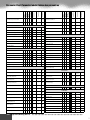
Style List ......................................................... 176
Multi Pad Bank List ......................................... 177
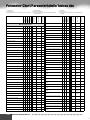
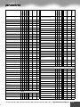
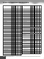
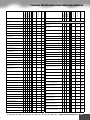
Parameter Chart ............................................. 178
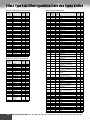
Effect Type List ............................................... 184
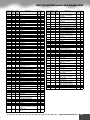
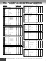
Effect Parameter List ...................................... 186
Effect Data Value Assign Tabl ......................... 191
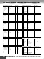
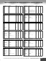
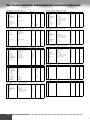
MIDI Data Format ........................................... 192
MIDI Implementation Chart ............................ 208
Specifications .................................................. 210
Disk Operations ........................................ 127
Loading Data from a Disk to Flash ROM ........128
Saving Data from Flash ROM to a Disk ..........129
Copying Files & Copying Floppy Disks ...........130
Backing Up/Restoring the Data in Flash ROM ..130
Converting files ...............................................131 *
Editing Disk Files ............................................131
Editing Directories ...........................................132
Formatting a Disk ............................................132
Checking a Disk ..............................................133
The PSR-9000 “Functions” ....................... 134
Master Tuning/Scale Tuning ............................134
Split Point/Chord Fingering .............................135
Controller Assignment .....................................135
Registration/Freeze Group/Voice Set Settings ..139
Harmony/Echo Settings ..................................140
Video Monitor Settings ....................................141
Talk Setting .....................................................141
Utility Settings .................................................142
The illustrations and LCD screens as shown in this owner’s manual are for
instructional purposes only, and may be different from your instrument.
7
●●●●●●●●●●●●●●●●●●●●●●●●●●●●●●●●●●●●●●●●●●●●●●●●●
9
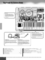
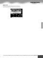
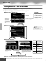
Top Panel & Connections
Air vent
!0
Do not place objects on the
instrument’s air vent, since this
may prevent adequate ventilation
of the internal components, and
possibly result in the instrument
overheating.
A
DIGITAL STUDIO
SOUND CREATOR
SAMPLING
CUSTOM VOICE
B
DIGITAL RECORDING
t
y
SONG
STYLE
8 BEAT
i
MIXING CONSOLE
DISK/
SCSI
LATIN
D
EFFECTS
FILTER/EQ
TUNING
MENU
& STYLE MANAGER
SWING & JAZZ
C
SONG
STYLE
MULTI PAD
FUNCTION
PART
MIDI
E
MULTIPAD
16 BEAT
SONG
PLAYER
R & B
MARCH & WALTZ
COUNTRY
BALLROOM
STOP
KEYBOARD TRANSPOSE
DANCE
SONG SETUP
o
DISKDIRECT
RESET
SONG FILE DIRECTORY
POWER
ON
OFF
MIN
w
MODULATION
UP
PRESET STYLE
u
MASTER VOLUME
q
PITCH BEND
AUTO
ACCOMPANIMENT
FLASH STYLE
TAP
INTRO
ENDING/rit.
TAP TEMPO
FADEIN/OUT
M.PAD BANK 1~60
!1
BANK VIEW
1
2
3
4
DIRECT
ACCESS
MAIN
MIXER
PART
ON/OFF
A
MAX
B
C
1
SYNC STOP SYNC START
ACCOMPANIMENT
CONTROL
PART
D
MAIN VARIATION
FILL IN & BREAK
START/STOP
MIC/LINE IN
MAX
OVER
SIGNAL
MIC1
MIC2
LINE
MIN
DOWN
e
r
MIN
MAX
INPUT VOLUME
PHONES
MIC/LINE IN
CLICK
T
S
R
L
L
M
H
M
H
L
H
L
M
L
M
H
C
1
H
Keyboard... page 137
INPUT VOLUME
control
PHONES
PHONES jack
A standard pair of stereo headphones can be
plugged in here for private practice or latenight playing. The internal stereo speaker
system is automatically shut off when a pair
of headphones is plugged into the PHONES
jack.
q
w
e
r
t
y
MIC/LINE IN
MIC/LINE IN jack
The PSR-9000 includes a microphone/line
input jack into which just about any standard
microphone or line-level source with a 1/4"
phone plug can be plugged (a dynamic
microphone with an impedance of 250 ohms
is recommended). The microphone or line
input can be used with the PSR-9000’s vocal
harmony function.
POWER ON/OFF switch.................................... 14
MASTER VOLUME control.............................. 14
PITCH BEND wheel .......................................... 54
MODULATION wheel....................................... 54
SONG buttons .............................................. 30, 66
STYLE buttons ................................................... 20
10
The keyboard of the PSR-9000 is
equipped with a touch response feature
(initial touch and after touch) that lets
you dynamically and expressively control the level of the voices with your
playing strength — just as on an acoustic instrument.
u
i
o
!0
!1
ACCOMPANIMENT CONTROL buttons ......... 20
MENU buttons.................................. 127, 134, 150
KEYBOARD TRANSPOSE buttons.................. 55
DIGITAL STUDIO buttons... 36, 40, 72, 88, 104, 119
MULTI PAD buttons............................. 34, 65, 119
●●●●●●●●●●●●●●●●●●●●●●●●●●●●●●●●●●●●●●●●●●●●●●●●
8
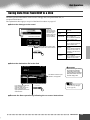
Top Panel & Connections
!3
LCD
CONTRAST
F
DEMO
VOICE EFFECT
!4
TOUCH
SUSTAIN
DSP(4~7)
SLOW/ FAST
G
H
HARMONY/ECHO
I
!5
POLY/ MONO
!9
PAGE CONTROL
BACK
EXIT
2
3
4
5
6
7
TEMPO
1
NEXT
!2
3
S
C
2
R
2
H
L
H
ORGAN
GUITAR
TRUMPET
SAXOPHONE
CHOIR & PAD
PERCUSSION
ORGAN FLUTES
TALK
E.PIANO
ACCORDION
STRINGS
BRASS
FLUTE
SYNTHESIZER
XG
CUSTOM VOICE
DSP(8)
2
!6 4
@0
PART SELECT
PROGRAMMABLE
ONE TOUCH SETTING
LEFT
RIGHT1
RIGHT2
REGISTRATION MEMORY
FREEZE
!7
8
LOWER
L
H
L
H
L
1
2
3
4
5
6
7
8
1
2
3
4
5
6
7
8
H
L
S
L
H
L
M
V.H. (9)
@2
SELECT
RESET
UPPER
PART ON/OFF
@3
UPPER OCTAVE
RIGHT3
@1
REGISTBANK 1~64
BANK VIEW
BEAT
R
PIANO
LEFT HOLD
DATA
ENTRY
R
1
VOCAL
HARMONY
VOICE
MUSIC DATABASE
J
MIC SETUP
MEMORY
REGISTRATION
DISK IN USE
ONE TOUCH SETTING
!8
O
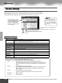
Liquid Crystal Display (LCD) and Related Buttons /Controls... page 42
Floppy Disk Drive... page 25, 30, 127
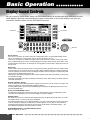
Large multi-function LCD display panel with display-based buttons, plus comprehensive display prompts and messages, makes operation easy and intuitive.
The PSR-9000 also features a built-in disk
drive that lets you save all your important
original data to floppy disk for future recall.
The PSR-9000 is compatible with a wide
variety of disk formats, allowing you to playback song data on commercially available
XG, GM , DOC, and Disklavier Piano Soft
disks.
Related Buttons/Controls :
• LCD(A-J) buttons
• LCD(1-8) buttons
• DIRECT ACCESS button
• MAIN MIXER button
• PART ON/OFF button
• EXIT button
• PAGE CONTROL buttons
• LCD CONTRAST control
!2
!3
!4
!5
!6
!7
Data dial.............................................................. 42
DEMO button ..................................................... 52
VOICE EFFECT buttons .............................. 35, 55
MUSIC DATABASE button ......................... 26, 64
ONE TOUCH SETTING button ................. 24, 61
REGISTRATION MEMORY buttons ................ 28
!8
!9
@0
@1
@2
@3
MEMORY button ......................................... 28, 61
VOICE buttons.................................................... 16
PART SELECT buttons ...................................... 53
PART ON/OFF buttons........................... 17, 18, 53
UPPER OCTAVE buttons................................... 55
VOCAL HARMONY buttons....................... 32, 68
9
●●●●●●●●●●●●●●●●●●●●●●●●●●●●●●●●●●●●●●●●●●●●●●●●●
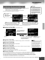
11
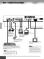
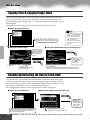
Rear Panel & Connections
MIDI A
IN
PC KEYBOARD
MIDI B
OUT
IN
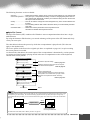
OUT
FOOT PEDAL
SWITCH 1
SWITCH 2
HOST SELECT TO HOST
VOLUME
PC-2
MIDI
CAUTION
SCSI
VIDEO OUT
RISK OF ELECTRIC SHOCK
DO NOT OPEN
PC-1
Mac
AVIS : RISQUE DE CHOC ÉLECTRIQUE–N
WARNING :
TO REDUCE THE RISK OF FIRE OR ELECT
DO NOT EXPOSE THIS PRODUCT TO RAIN
MIDI A
NTSC/PAL
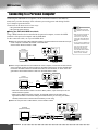
Sequencer
One or two optional
Yamaha FC5
footswitches connected
to these jacks can be
used to control sustain
and a range of other
important functions.
Refer to page 136.
Computer
(with music software)
The sophisticated MIDI functions
give you powerful tools to expand
your music performance and
creation possibilities.
Refer to page 144.
[VIDEO IN]
An optional Yamaha FC7 Foot
Controller connected to this jack can
be used to control volume and a
range of other important functions.
Refer to page 135.
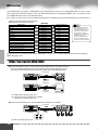
You can connect a computer keyboard to the PSR-9000 for inputting
song and file names or Voice/Style/Song/Registration Memory
numbers. This function is also very convenient in Step recording.
Please note that Macintosh computer keyboards cannot be used with
the PSR-9000.
Refer to pages 44, 103, and 143.
• A computer keyboard can only be used if it has
been connected to the PSR-9000 before turning
the power on. If you have connected a computer
keyboard after turning the power on, simply turn
the power off and back on again.
12
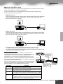
Television
You can connect the PSR-9000 to a television
or video monitor to display the lyrics and chords
in your song data on a larger screen.
Refer to page 141.
• The PSR-9000’s default setting for the external
television/video monitor signal is “PAL.”
Depending on your particular locale, the standard may be different and the setting should be
changed accordingly. (For example, NTSC is
generally used in North America.) Check the
standard used by your television or video monitor, and if it is not PAL, change the setting in the
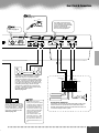
VIDEO OUT display to “NTSC” (page 141).
●●●●●●●●●●●●●●●●●●●●●●●●●●●●●●●●●●●●●●●●●●●●●●●●
10
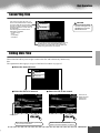
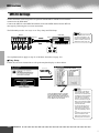
Rear Panel & Connections
Refer to page 14.
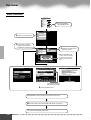
AC INLET
The TRIM control allows the
input sensitivity of the AUX IN
L/L+R and R (LOOP RETURN)
jacks to be adjusted for
optimum level matching with
the connected equipment.
Refer to page 14.
AC INLET
1
R
L/L+R
AUX IN/ LOOP RETURN
TRIM
R
L/L+R
LOOP SEND
R
L/L+R
220V
CK
LINE OUT
2
240V
0V
11
13
0V
NE PAS OUVRIR.
TRIC SHOCK,
N OR MOISTURE.
MIN
SUB
MAX
MAIN
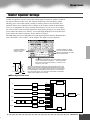
Stereo System
The LINE OUT jacks are used to send the
PSR-9000 output to a keyboard amplifier,
stereo sound system, mixing console, or tape
recorder. If you are connecting the PSR-9000
to a mono sound system, use only the L/L+R
jack. When only this jack is connected (using
a standard phone plug), the left and right
channels are combined and output through
this jack — allowing you have a mono mix of
the PSR-9000's stereo sound.
Refer to page 126.
MONITOR
OUT
INPUT
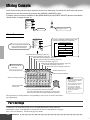
Mixer
INPUT
STEREO OUT
Sound source
PA
Sound source
This SCSI-2 50-pin connector
(D-sub, half-pitch) can be used
to connect to an external SCSI
data storage device — allowing
you to conveniently save and
store large quantities of data.
Refer to page 127.
• Depending on the SCSI
device, you may need a special
connecting cable or adaptor to
connect the device properly to
the PSR-9000. Make sure to
confirm the connection configuration of both the PSR-9000
and the SCSI device before
purchasing the device.
• The SCSI ID number of the
PSR-9000 is fixed at 7. Make
sure to set the ID number of
the external SCSI device to a
number other than this (i.e., 0 6).
Connection Examples
In this setup, the sound of the PSR-9000 itself as well as the
external sources is reproduced via the PSR-9000's built-in
amplifier and speakers, allowing the PSR-9000 to function as
a convenient stage monitor system.
11
●●●●●●●●●●●●●●●●●●●●●●●●●●●●●●●●●●●●●●●●●●●●●●●●●
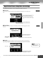
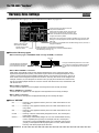
13
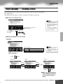
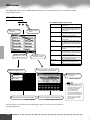
Starting Up
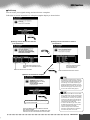
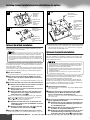
Check Your Power Supply
Voltage Selector
AC INLET
220
V
240V
11
0V
13
0V
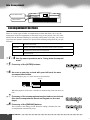
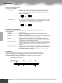
Make sure that your local AC mains voltage matches the voltage specified on the
name plate on the bottom panel. In some areas a voltage selector may be provided on
the rear panel of the PSR-9000 near the power cord. Make sure that the voltage selector is set for the voltage in your area. The voltage selector is set at 240V when the unit
is initially shipped.
To change the setting use a slotted (“minus”) screwdriver to rotate the selector dial so
that the correct voltage appears next to the pointer on the panel. Make sure that the
power is turned off before changing the Voltage Selector setting.
The configuration of the
AC INLET may be different depending on your
particular locale.
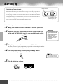
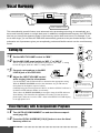
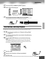
Use the following procedure to start up the PSR-9000.
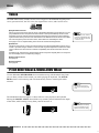
1 Make sure that the POWER switch is in the OFF (extended)
position.
2 Securely plug the “female” end of the AC power cord sup-
plied with the PSR-9000 into the rear-panel AC cord socket.
AC INLET
WARNING
• Use only the AC power cord
supplied with the PSR-9000.
If the supplied cord is lost or
damaged and needs to be
replaced, contact your
Yamaha dealer. The use of
an inappropriate replacement can pose a fire and
shock hazard!
3 Plug the power cord into a convenient AC outlet.
In some areas, an AC plug adaptor may be provided to match the pin configuration of the AC wall outlets in your area.
4 Turn the power ON by pressing the [POWER] switch.
Press the [POWER] switch again to turn the power OFF.
POWER
ON
OFF
• When turning the power OFF,
simply reverse the procedure.
5 Play & adjust the volume.
MASTER VOLUME
MIN
14
MAX
●●●●●●●●●●●●●●●●●●●●●●●●●●●●●●●●●●●●●●●●●●●●●●●●
12
Starting Up
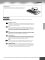
Music stand
The PSR-9000 is supplied with a music stand that can be attached to the
instrument by inserting it into the holes at the rear of the speaker panel.
Panel logos
The logos printed on the PSR-9000 panel indicate the standards/formats it supports and
special features it includes.
GM System Level 1
GM System Level 1 is an addition to the MIDI standard which guarantees that any data
conforming to the standard will play accurately on any GM-compatible tone generator
or synthesizer from any manufacturer.
XG
XG is a new Yamaha MIDI specification which significantly expands and improves on
the GM System Level 1 standard with greater voice handling capacity, expressive control, and effect capability while retaining full compatibility with GM. By using the PSR9000’s XG voices, it is possible to record XG-compatible song files.
XF
The Yamaha XF format enhances the SMF (Standard MIDI File) standard with greater
functionality and open-ended expandability for the future. The PSR-9000 is capable of
displaying lyrics when an XF file containing lyric data is played.
Vocal Harmony
Vocal Harmony employs state-of-the-art digital signal processing technology to automatically add appropriate vocal harmony to a lead vocal line sung by the user. Vocal
Harmony can even change the character and gender of the lead voice as well as the
added voices to produce a wide range of vocal harmony effects.
DOC
The DOC voice allocation format provides data playback compatibility with a wide
range of Yamaha instruments and MIDI devices, including the Clavinova series.
Style File Format
The Style File Format — SFF — is Yamaha’s original style file format which uses a
unique conversion system to provide high-quality automatic accompaniment based on
a wide range of chord types. The PSR-9000 uses the SFF internally, reads optional
SFF style disks, and creates SFF styles using the Style Creator function.
13
●●●●●●●●●●●●●●●●●●●●●●●●●●●●●●●●●●●●●●●●●●●●●●●●●
15
Quick Guide
●●●●●●●●●●●●●●●●●
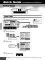
Playing Voices
Voice related buttons
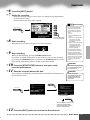
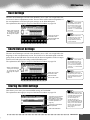
Playing a Voice
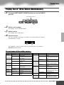
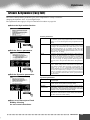
1 Press the [R1] LCD button to turn the RIGHT1 part on.
• The voice selected here is
called voice RIGHT 1.
See page 53 for more information on voice RIGHT1.
F
G
H
PART SELECT
I
LEFT HOLD
LEFT
RIGHT1
RIGHT2
RIGHT3
J
LOWER
PART ON/OFF
UPPER
2 Select a voice group.
VOICE
PIANO
ORGAN
GUITAR
E.PIANO
ACCORDION
STRINGS
For this example, STRINGS
is selected.
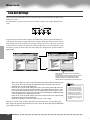
3 Select a voice.
A
B
For this example,
Live! Orch is
selected.
C
D
E
Press the corresponding buttons to
select the various pages.
4 Play the voices.
16
Quick Guide ● ● ● ● ● ● ● ● ● ● ● ● ● ● ● ● ● ● ● ● ● ● ● ● ● ● ● ● ● ● ● ● ● ● ● ● ● ● ● ● ● ●
14
Playing Voices
Playing Two or Three Voices Simultaneously
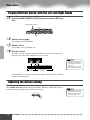
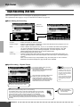
1 Press the PART ON/OFF [RIGHT2] button to turn the RIGHT2
part ON.
Automatically turned on
PART SELECT
LEFT HOLD
LEFT
LOWER
RIGHT1
PART ON/OFF
RIGHT2
RIGHT3
UPPER
2 Select a voice group.
3 Select a voice.
4 Play the voices.
For example, select “CHOIR & PAD.”
For example, select “Hah Choir.”
The voice selected for R1 (page 16) and the voice selected here are sounded
simultaneously in a layer.
Voice RIGHT 3 can be set in the same way described above, by using the
[RIGHT3] button instead.
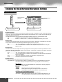
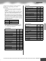
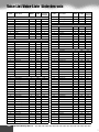
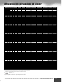
Try out some of these other voices...
Category
E.Piano
Voice Name
Galaxy EP
Stage Ep
Organ
Cool! Jazz
Rotor Organ
Accordion
Musette
Guitar
Live! Nylon
Strings
Cool! J.Gtr
Live! Strs
Trumpet
Sweet Trump
Sweet Tromb
Comment
Rich and dynamic DX-type
electric piano.
3 different dynamics sampled
for realistic and expressive timbre changes.
Organ sample with authentic
chorus vibrato.
Organ sample with real rotary
speaker.
Realistic, French type accordion.
Stereo sampled nylon guitar.
Dedicated flageolet sample for
high velocities.
Dynamic, fingered jazz guitar.
Rich, stereo sampled strings
orchestra.
Expressive trumpet with natural vibrato.
Realistic trombone with natural
vibrato.
Category
Saxophone
Voice Name
Sweet Tenor
Sweet Sprno
Sweet Clari
Flute
Sweet Flute
Sweet Pan
Choir&Pad
Live!Gospel
Live! Vocal
Synthesizer
DreamHeaven
MATRIX
Percussion
Live!StdKit
Comment
Smooth tenor sax with natural
vibrato.
Soprano sax with natural vibrato. Very expressive. Play long
notes.
Jazzy clarinet with natural vibrato.
Flute with natural vibrato. Very
expressive. Play strong to get
realistic overblown sample.
Authentic pan flute with natural
vibrato
Stereo choir with individual,
smooth vibrato
Dynamic vocal sounds — that
change with your playing
strength. Play bass vocals with
your left hand.
Beautiful synth pad
Expressive synth lead. Play
long notes.
Stereo sampled drums with velocity switch up to 4 layers.
Also check out Live! Funk Kit.
15
●●●●●●●●●●●●●●●●●●●●●●●●●●●●●●●●●●●●●●●●●●
Quick Guide
17
Playing Voices
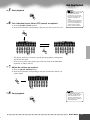
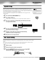
Playing Different Voices with the Left and Right Hands
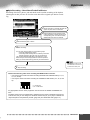
1 Press the PART ON/OFF [LEFT] button to turn the LEFT part
ON.
Automatically turned on
PART SELECT
LEFT HOLD
LEFT
RIGHT1
LOWER
PART ON/OFF
RIGHT2
RIGHT3
UPPER
2 Select a voice group.
3 Select a voice.
4 Play the voices.
For example, select “STRINGS.”
For example, select “Symphon. Str.”
The notes you play with your left hand sound one voice, while the notes you
play with your right sound a different voice (or voices).
• The point on the keyboard that
separates voice LEFT and
voice RIGHT1~3 is called the
“split point.”
Refer to page 135 for instructions on setting the split point.
Split Point
Voice R1, R2, R3
(Upper)
Voice L
(Lower)
Voices RIGHT 1~3 are meant to be played with the right hand. Voice LEFT is
played with the left hand.
Adjusting the Octave setting
The [UPPER OCTAVE] button allows the RIGHT1, RIGHT2, and RIGHT3 parts to
be simultaneously transposed up or down by one octave.
UPPER OCTAVE
• More detailed octave-related
settings for each part can be
made by using the Mixing Console function (page 123).
RESET
18
Quick Guide ● ● ● ● ● ● ● ● ● ● ● ● ● ● ● ● ● ● ● ● ● ● ● ● ● ● ● ● ● ● ● ● ● ● ● ● ● ● ● ● ● ●
16
Playing Voices
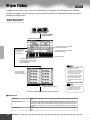
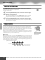
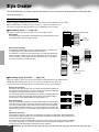
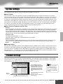
Organ Flutes
The Organ Flutes function lets you create your own original organ voices, just as on a
traditional organ, by increasing and decreasing the levels of the flute footages.
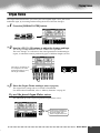
1 Press the [ORGAN FLUTES] button.
CHOIR & PAD
PERCUSSION
ORGAN FLUTES
SYNTHESIZER
XG
CUSTOM VOICE
2 Use the LCD [1] - [8] buttons to adjust the footage settings.
The footage settings determine the basic sound of the organ flutes.
The term “footage” is a reference to the sound generation of traditional pipe
organs, in which the sound is produced by pipes of different lengths (in feet).
Use button [1] to adjust the 16’
or 8’ footage. You can select
the desired footage (16’ or 8’)
with the [E] LCD button.
1
2
3
4
3 Store the Organ Flutes settings.
5
6
7
8
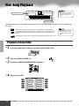
(Refer to page 56.)
The Organ Flutes settings above are stored to Flash ROM.
For details about Flash ROM, refer to “Memory Structure” on page 50.
Try out the preset Organ Flutes voices
The PSR-9000 provides 10 pre-programmed Organ Flutes voices.
F
G
H
I
J
Press the [H] LCD button to
call up the Organ Flutes preset voices display, then
select an Organ Flutes voice.
17
●●●●●●●●●●●●●●●●●●●●●●●●●●●●●●●●●●●●●●●●●●
Quick Guide
19
Auto Accompaniment
Style related buttons
Auto Accompaniment
related buttons
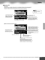
Using Auto Accompaniment
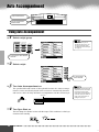
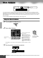
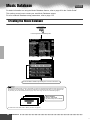
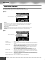
1 Select a style group.
STYLE
8 BEAT
& STYLE MANAGER
SWING & JAZZ
• The PSR-9000 styles are
divided into two groups : Preset styles and Flash styles.
For details about Flash styles,
see page 51.
LATIN
16 BEAT
R & B
MARCH & WALTZ
DANCE
COUNTRY
BALLROOM
PRESET STYLE
For this example, BALLROOM
is selected.
2 Select a style.
F
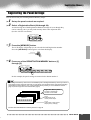
G
H
I
J
For this example,
Jive is selected.
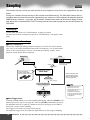
3 Turn Auto Accompaniment on.
The specified left-hand section of the keyboard becomes the “Auto Accompaniment” section, and chords played in this section are automatically detected
and used as a basis for fully automatic accompaniment with the selected style.
Split Point
• The point on the keyboard that
separates the auto accompaniment section and the righthand section of the keyboard is
called the “split point.” Refer to
page 135 for instructions on
setting the split point.
AUTO
ACCOMPANIMENT
Auto Accompaniment
section
4 Turn Sync Start on.
The beat lamp also flashes in time with the tempo. This condition is called synchronized start standby.
BEAT
SYNC STOP SYNC START
20
Quick Guide ● ● ● ● ● ● ● ● ● ● ● ● ● ● ● ● ● ● ● ● ● ● ● ● ● ● ● ● ● ● ● ● ● ● ● ● ● ● ● ● ● ●
18
Auto Accompaniment
5 As soon as you play a chord with your left hand, the auto
accompaniment starts.
For this example, play a C major chord (as shown below).
Split Point
Auto Accompaniment
section
6 Try playing other chords with your left hand.
7 Press the [START/STOP] button again to stop the accompaFor information on how to enter chords, see “Chord Fingerings” on page 58.
niment.
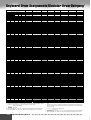
Try out some of the other styles...
Category
8 BEAT
16 BEAT
DANCE
Style Name
Heart Beat
Comment
Standard 8-beat pop. Enjoy the
sound of the strumming guitars.
Spicy Beat
Modern 8-beat that uses the Hit and
Live! Standard drum kits.
8Beat Adria
This gorgeous style evokes the north
Mediterranean, but can be used well
for a variety of songs.
AcousticBld
An unplugged style with a half-time
3/4 feel. Check out the great guitar
sounds.
Slow & Easy This style evokes the sophisticated,
relaxed atmosphere of a modern jazz
club.
Smooth Jazz Enjoy the Latin feel of this modern fusion style.
House Musik Analog synths, techno drums, rave
beat — today’s modern dance music
at your fingertips.
DiscoChoco Try starting this classic 70’s disco
style with Intro III.
Flip Hop
This contemporary hip hop rhythm
features sine wave acid lines and
high-pitched snare. Rap along with
this!
Category
SWING&
JAZZ
Style Name
Big Band 3
Comment
Traditional big band style especially
suited for ballads and slow blues.
Swingfox
Check out the different major and minor patterns for Intro III. This style is
good for a wide wide range of songs.
BBandBallad This style is perfect for recreating the
sound and atmosphere of the great big
bands and orchestras of the swing era.
Piano Swing A swinging Pianist style. Turn the
CHD1 (chord) part on and off for different arrangements.
R&B
SoulShuffle
Check out the dynamic sounds of the
Live! Standard drum kit, especially in
the Break fill pattern.
GospelBros
Check out the different gospel
grooves in the Main A - D patterns.
Boogie 1
Start this out without the drums and
bass, then bring them in for a full-tilt
boogie band.
RockShuffle This heavy rock shuffle features the
distortion effect on the guitar.
COUNTRY Country 2/4
This driving country-pop style can be
used for a variety of other music
styles as well.
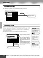
LATIN
Samba City
This contemporary Samba-pop style
features dynamic toms from the new
Live! drum kit. Check out Ending III.
BALLROOM Engl.Waltz
A fully orchestrated, luscious waltz style,
perfect for elegant ballroom dancing.
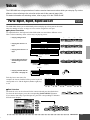
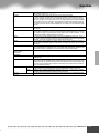
■ Metronome and Bass Chord Hold
These are two special styles designed for practice purposes; they do not have any of the
normal rhythm or accompaniment patterns of the other styles. To call them up, select
Page 2 of the Ballroom category by pressing the [P2] button.
● Metronome
This style plays back only a metronome click, without any other rhythm parts. Use this as you
would a normal metronome, practicing in time with the click. You can adjust the tempo with
the data dial. Playing chords in the Auto Accompaniment section of the keyboard produces
corresponding bass notes and chords, just as in Bass Chord Hold below. There are five different metronome settings, each with a different time signature.
● Bass Chord Hold
Even with the auto accompaniment turned on, this style does not play any rhythm parts, but
simply holds the bass note and chord that correspond to the chord you play in the Auto
Accompaniment section of the keyboard. this is convenient for practicing chords without having to play along with a rhythm. There are five different bass note/chord settings, each with
different voices.
19
●●●●●●●●●●●●●●●●●●●●●●●●●●●●●●●●●●●●●●●●●●
Quick Guide
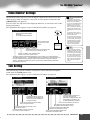
21
Auto Accompaniment
Style related buttons
Auto Accompaniment
section buttons
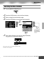
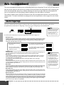
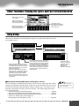
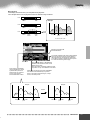
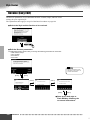
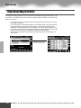
Accompaniment Sections
There are various types of Auto Accompaniment sections that allow you to vary the
arrangement of the accompaniment to match the song you are playing. They are: Intro,
Main, Fill-in & Break and Ending. By switching among them as you play, you can easily produce the dynamic elements of a professional-sounding arrangement in your performance.
INTRO
This is used for the beginning of the song. When the intro finishes playing, accompaniment
shifts to the main section.
MAIN
This is used for playing the main part of the song. It plays an accompaniment pattern of several
VARIATION
measures, and repeats indefinitely until another section’s button is pressed.
FILL IN & BREAK This lets you add dynamic variations and breaks in the rhythm of the accompaniment, to make
your performance sound even more professional.
ENDING
This is used for the ending of the song. When the ending is finished, the auto accompaniment
stops automatically.
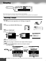
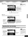
1 - 4 Use the same operations as in “Using Auto Accompaniment.”
5 Press any of the [INTRO] buttons.
TAP
INTRO
TAP TEMPO
6 As soon as you play a chord with your left hand, the auto
accompaniment starts.
For this example, play a C major chord (as shown below).
Split Point
Auto Accompaniment
section
When the playback of the intro is finished, it automatically leads into main section.
7 Press any of the accompaniment section buttons as desired.
(See the Accompaniment Structure Diagram on the next
page.)
FILL IN & BREAK
8 Press any of the [ENDING] buttons.
This switches to the ending section. When the ending is finished, the auto
accompaniment automatically stops.
22
ENDING/rit.
FADEIN/OUT
Quick Guide ● ● ● ● ● ● ● ● ● ● ● ● ● ● ● ● ● ● ● ● ● ● ● ● ● ● ● ● ● ● ● ● ● ● ● ● ● ● ● ● ● ●
20
Auto Accompaniment
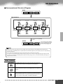
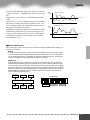
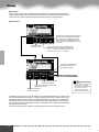
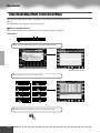
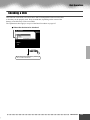
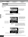
■ Accompaniment Structure Diagram
INTRO
INTRO I
INTRO II
INTRO III
MAIN VARIATION
via FILL IN A
via FILL IN B
via FILL IN B
MAIN
VARIATION
A
via FILL IN D
via FILL IN C
via FILL IN C
MAIN
VARIATION
B
via FILL IN A
via BREAK
via FILL IN D
via FILL IN D
MAIN
VARIATION
C
via FILL IN B
via BREAK
via FILL IN A
MAIN
VARIATION
D
via FILL IN C
via BREAK
via BREAK
Press the one of the [ENDING]
buttons.
ENDING
ENDING I
ENDING II
ENDING III
You can have the ending gradually
slow down (ritardando) by pressing
the same [ENDING] button again
while the ending is playing back.
• You can use one of the intro sections even in the middle of the song by pressing one of the [INTRO] buttons during the song.
• If one of the [FILL IN & BREAK] buttons is pressed after the final half beat (eighth note) of the measure, the fill-in or break will begin
from the next measure.
• You can begin the accompaniment by using any of the other sections, as well as the intro sections.
• If you press one of the [INTRO] buttons while the ending is playing, the intro section will begin playing after the ending is finished.
• If you press one of the [FILL IN & BREAK] buttons while the ending is playing, the fill-in or break will immediately start playing, continuing with the main section.
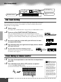
Other Controls
FADE IN/OUT
The [FADE IN/OUT] button can be used to produce smooth fade-ins
and fade-outs when starting and stopping the accompaniment.
FADEIN/OUT
TAP TEMPO
TAP
The auto accompaniment can be started at any tempo you desire by
“tapping” out the tempo with the [TAP/TEMPO] button. For details, see
page 60.
TAP TEMPO
SYNCRO STOP When the Synchro Stop function is engaged, accompaniment playback
will stop completely when all keys in the auto-accompaniment section of
the keyboard are released. Accompaniment playback will start again as
soon as a chord or note is played. For details, see page 61.
SYNC STOP
21
●●●●●●●●●●●●●●●●●●●●●●●●●●●●●●●●●●●●●●●●●●
Quick Guide
23
Auto Accompaniment
MAIN MIXER and
PART ON/OFF buttons
ONE TOUCH SETTING
buttons
DISK DIRECT buttons
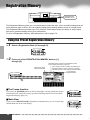
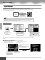
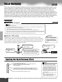
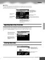
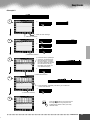
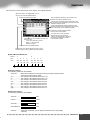
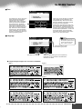
One Touch Setting
One Touch Setting is a powerful and convenient feature that automatically calls up the
most appropriate panel settings (voice number, etc.) for the currently selected style,
with the touch of a single button.
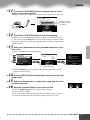
1 Select a style.
2 Press one of the [ONE TOUCH SETTING] buttons.
For example, select “SWING & JAZZ” category and try out “BBand Ballad” (on P2).
Auto Accompaniment and Sync Start will automatically be turned on.
In addition, various panel settings (such as voices, effects, etc.) that match the
selected style can be instantly recalled with just a single button press (see page
178).
3 As soon as you play a chord with your left hand, the auto
accompaniment starts.
4 Play melodies with your right hand and play various chords
with your left hand.
5 Try out other One Touch Setting setups.
1
2
3
4
1
2
3
4
PROGRAMMABLE
ONE TOUCH SETTING
Split Point
Auto Accompaniment
section
PROGRAMMABLE
You can also create your own One Touch Setting setups.
For details, refer to page 61.
ONE TOUCH SETTING
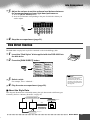
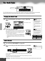
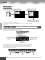
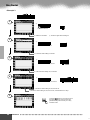
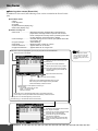
Track Muting & Volume Control
1 Turn Auto Accompaniment on and start the accompaniment
(page 20).
2 Turn individual tracks ON or OFF (muted) as required.
1) Press the [PART ON/OFF] button.
2) Press the LCD button corresponding to the part you wish to turn on or off.
PART
ON/OFF
PART
1
24
2
3
4
5
6
7
8
• The **PART** mark below the
[PART ON/OFF] button indicates that pressing the button
repeatedly switches among
various different displays.
However, in the example explanation shown here, only the
accompaniment parts are displayed; no other displays can
be called up, no matter how
many times the button is
pressed. Other displays can
be called up when Song Player
(page 30) is set to on, or when
the Digital Recording mode is
active.
Quick Guide ● ● ● ● ● ● ● ● ● ● ● ● ● ● ● ● ● ● ● ● ● ● ● ● ● ● ● ● ● ● ● ● ● ● ● ● ● ● ● ● ● ●
22
Auto Accompaniment
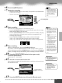
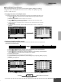
3 Adjust the volume to set the optimum level balance between
the accompaniment and your right hand performance.
1) Press the [MAIN MIXER] button.
2) Press the LCD button corresponding to the part of which the volume you
wish to adjust.
MAIN
MIXER
1
2
3
4
5
6
7
8
4 Stop the accompaniment (page 21).
Disk Direct Function
The PSR-9000 can play back style files contained on the included floppy disk.
1 Insert the “Disk Styles” disk supplied with the PSR-9000 into
the disk drive.
2 Press the [DISK DIRECT] button.
DISKDIRECT
• It may be necessary to wait for
a while in step #3 until the
PSR-9000 can play the accompaniment, since it takes some
time to read the style data from
the floppy disk.
3 Select a style.
4 Play the auto accompaniment (page 22).
For example, select “16Balad3.”
■ About the Style Data
This diagram illustrates the relationship among the style data stored to different types
of memory. Refer to “Memory Structure” on page 50.
Accompaniment playback
Disk Direct
Preset Style
Flash Style
Save
See above.
Disk Style
Load
Style Manager
Store
Style Creator
See page 62.
See page 104.
23
●●●●●●●●●●●●●●●●●●●●●●●●●●●●●●●●●●●●●●●●●●
Quick Guide
25
Music Database
MUSIC DATABASE
button
If you want to play in a certain genre of music but don’t know which style and voice settings would be
appropriate, the convenient Music Database can help you out. Simply select the desired genre from the
Music Database and the PSR-9000 automatically makes all appropriate panel settings to let you play in
that music style!
For a list of Music Database setup parameters, refer to page 178.
Using the Music Database
1 Press the [MUSIC DATABASE] button.
MUSIC DATABASE
2 Select a Music Database.
Press this to actually call up the
Music Database
Select the desired
Category.
1
2
3
4
5
6
7
8
Select the desired Music Database.
Use button [4] or [5] to move the
cursor to the desired location and
press the [OK] LCD button to
actually call up the Music Database.
Move the cursor to the desired
location by using button [6] or [7]
to call up the Music Database.
(You need not press the [OK] LCD
button.)
You can use the Data
dial to select the desired
Music Database.
For example, try out Category “Great Pop Songs” and Music Database “Called
to say.”
3 Play along with the accompaniment playback.
Split Point
Auto Accompaniment
section
26
Quick Guide ● ● ● ● ● ● ● ● ● ● ● ● ● ● ● ● ● ● ● ● ● ● ● ● ● ● ● ● ● ● ● ● ● ● ● ● ● ● ● ● ● ●
24
Music Database
Searching the Music Database
1 Press the [MUSIC DATABASE] button.
MUSIC DATABASE
2 Press the LCD [F] button to call up the Search display.
3 Select a category and set the tempo range.
4 Press the LCD [I] button to execute the Search operation.
2
F
F
G
G
H
H
I
I
J
J
4
1
2
3
4
5
6
7
8
3
Press this button to call
up the Keyword display, from which you
can enter a keyword
and search the Music
Database.
5 Select a Music Database (see step #2 on page 26) and play
along with the accompaniment playback.
Split Point
Auto Accompaniment
section
You can also create your own Music Database setups.
For details, refer to page 64.
25
●●●●●●●●●●●●●●●●●●●●●●●●●●●●●●●●●●●●●●●●●●
Quick Guide
27
Registration Memory
REGISTRATION
MEMORY buttons
The Registration Memory gives you a convenient way to select the style, voice, and effect settings that will
suit a particular type of music. You can instantly change panel settings with the touch of a single button.
The Registration Memory provides up to 512 complete control-panel setups (64 banks, 8 setups each)
that can be recalled instantly during your performance.
For a list of Registration Memory setup parameters, refer to page 178.
Using the Preset Registration Memory
1 Select a Registration Bank (01 through 03).
REGISTRATION MEMORY
FREEZE
REGISTBANK 1~64
BAN
1
2
3
1
2
3
2 Press one of the REGISTRATION MEMORY buttons: [1]
through [8].
Registration Name entered via the Registration Name
function display described on page 139.
Indicates the Registration Bank/Number.
If any change is made to a setting memorized by the
Registration Memory feature, a pencil icon appears,
indicating that one or more settings have been edited.
Current selected
Registration Bank
REGISTRATION MEMORY
FREEZE
REGISTBANK 1~64
BANK VIEW
1
2
3
4
5
6
7
8
1
2
3
4
5
6
7
8
■ The Freeze function
If you press the [FREEZE] button so that its lamp lights, selecting a different registration setup will not change the settings specified in the Registration Freeze Group Setting function display (page 139).
REGISTRATION MEMORY
FREEZE
REGISTBANK 1~64
BAN
1
2
3
1
2
3
■ Bank View
If you press the REGIST BANK [+]/[-] buttons simultaneously, you can view the Registration Bank list on the LCD display.
28
REGISTRATION MEMORY
FREEZE
REGISTBANK 1~64
BAN
1
2
3
1
2
3
Quick Guide ● ● ● ● ● ● ● ● ● ● ● ● ● ● ● ● ● ● ● ● ● ● ● ● ● ● ● ● ● ● ● ● ● ● ● ● ● ● ● ● ● ●
26
Registration Memory
Registering the Panel Settings
You can also create your own Registration Memory setups.
1 Set up the panel controls as required.
2 Select a Registration Bank (04 through 64).
Avoid selecting one of the Registration Banks 01 through 03 (even though they
can be selected), since you may inadvertently delete some important data.
(See the “NOTE” note below.)
REGISTRATION MEMORY
FREEZE
REGISTBANK 1~64
BAN
1
2
3
1
2
3
3 Press the [MEMORY] button.
The LCD display will prompt you to select the desired Registration number.
Press the [MEMORY] button again to exit from this display.
MEMORY
REGISTRATION
ONE TOUCH SETTING
one of the REGISTRATION MEMORY buttons: [1]
4 Press
through [8].
REGISTRATION MEMORY
FREEZE
REGISTBANK 1~64
BANK VIEW
1
2
3
4
5
6
7
8
1
2
3
4
5
6
7
8
In this example, the panel settings are memorized to button number 3.
Since all Registration Memory data is stored to Flash ROM, any data in the Registration Memory location you selected
in step #2 above will be erased and replaced by your new settings. This includes the factory programmed preset Registration Memory settings (banks 01 - 03). If you've deleted the factory-set data, you can use the Restore function
(page 130) to load a copy of it from the included disks (page 6).
Registration Memory banks
64 banks in Flash ROM
All banks can be edited.
04~64
These banks do not
contain preset setups.
BANK 01
1
2
3
4
5
6
7
8
01~03
These banks contain preset
setups (factory settings).
For details about Flash ROM, refer to “Memory Structure” on page 50.
27
●●●●●●●●●●●●●●●●●●●●●●●●●●●●●●●●●●●●●●●●●●
Quick Guide
29
Disk Song Playback
• Make sure to read the section
“Using the Floppy Disk Drive
(FDD) and Floppy Disks” on
page 5.
Song related buttons
Floppy disk drive
The following disks are compatible for playback on the PSR-9000. Refer to page 15 for more details on
the logos.
Disks bearing this logo contain song data for voices defined in the GM standard.
Disks bearing this logo contain song data using the XG format, an extension of the
GM standard that provides a wider variety of voices and more comprehensive sonic
control.
• GM song files not having the
extension “.MID” in the name
cannot be handled by the PSR9000.
Disks bearing this logo contain song data for voices defined in Yamaha’s DOC format.
Playback of Song Disks
1 Insert the disk that contains song data into the disk drive.
2 Turn the SONG PLAYER on.
3 Press the SONG FILE DIRECTORY [I] button.
SONG
PLAYER
SONG
SONG SETUP
SONG FILE DIRECTORY
4 Select a song file.
30
A
F
B
G
C
H
D
I
E
J
Quick Guide ● ● ● ● ● ● ● ● ● ● ● ● ● ● ● ● ● ● ● ● ● ● ● ● ● ● ● ● ● ● ● ● ● ● ● ● ● ● ● ● ● ●
28
Disk Song Playback
5 Start playback.
• With song data software (Standard MIDI format 0) that
includes lyrics, you can view
the lyrics in the display during
playback. See page 67 for
details.
For appropriate song data, the
PSR-9000 can display the lyrics in one of five different languages: English, German,
French, Spanish and Italian.
START/STOP
6 Turn individual tracks ON or OFF (muted) as required.
1) Press the [PART ON/OFF] button.
2) Press the LCD button corresponding to the part you wish to turn on or off.
PART
ON/OFF
PART
PART
ON/OFF
1
2
3
4
5
6
7
8
1
2
3
4
5
6
7
8
PART
• The SOLO mode lets you select a specific part for playback, muting (turning off) all other parts.
• If you wish to practice the melody part of the XG song on the PSR-9000
keyboard, set TR1 to MUTE.
7 Adjust the volume as required.
1) Press the [MAIN MIXER] button.
2) Press the LCD button corresponding to the part of which the volume you
wish to adjust.
MAIN
MIXER
1
2
8 Stop playback.
START/STOP
3
4
5
6
7
8
• The [FADE IN/OUT] button
(page 60) can be used to produce smooth fade-ins and
fade-outs when starting and
stopping the song, as well as
the accompaniment.
29
●●●●●●●●●●●●●●●●●●●●●●●●●●●●●●●●●●●●●●●●●●
Quick Guide
31
Vocal Harmony
CAUTION
MIC/LINE IN buttons
Pickup of extraneous sounds from
the microphone can cause distorted
Vocal Harmony sound.
• Separate the microphone from the
instrument’s speakers as much as
possible.
VOCAL HARMONY buttons
This extraordinarily powerful feature uses advanced voice-processing technology to automatically produce vocal harmony based on a single lead vocal. In addition to straightforward harmony, the PSR-9000
also lets you change the apparent gender of the harmony and/or lead vocal sound. For example, if you
are a male singer, you can have the PSR-9000 automatically generate a two-part female backup. A comprehensive set of parameters gives you exceptionally precise and flexible control over the vocal harmony
sound.
MIC/LINE IN
OVER
Setting Up
SIGNAL
MIC1
MIC2
LINE
1 Set the INPUT VOLUME control to “MIN.”
2 Set the MIC/LINE panel switch to “MIC 1” or “MIC 2.”
This is a gain control for the microphone input signal. The “MIC 1” setting
boosts the signal, while the “MIC 2” setting reduces it.
2
1
MIN
MAX
INPUT VOLUME
MIC/LINE IN
OVER
SIGNAL
3 Connect a microphone to the MIC/
LINE IN jack of the PSR-9000.
4 Adjust the INPUT VOLUME control
MIC1
MIC2
LINE
PHONES
MIC/LINE IN
while singing into the microphone.
Use the SIGNAL and OVER indicators to determine the appropriate setting.
With the INPUT VOLUME control at the minimum, sing or talk into the
microphone at the highest expected volume.
Gradually bring the control up toward “MAX” so that the SIGNAL indicator is
lit and the OVER indicator flashes occasionally.
Then reduce the INPUT VOLUME just enough to keep the OVER indicator
from flashing. This should be the optimum level setting. To hear the microphone input, make sure to set the “MIC” fader in the MAIN VOLUME display
to an appropriate level.
4
MIN
MAX
INPUT VOLUME
• Refer to the important notes
and caution message on page
68.
• Turn the INPUT VOLUME control all the way down when disconnecting a microphone.
Vocal Harmony with Accompaniment Playback
1 Turn AUTO ACCOMPANIMENT on and start the accompaniment (page 20).
2 Press the VOCAL HARMONY [V.H.(9)] button to turn the Vocal
Harmony effect on.
VOCAL
HARMONY
TALK
DSP(8)
V.H. (9)
SELECT
MIC SETUP
32
Quick Guide ● ● ● ● ● ● ● ● ● ● ● ● ● ● ● ● ● ● ● ● ● ● ● ● ● ● ● ● ● ● ● ● ● ● ● ● ● ● ● ● ● ●
30
Vocal Harmony
3 Press the VOCAL HARMONY [SELECT] button.
4 Select a Vocal Harmony type.
VOCAL
HARMONY
TALK
A
DSP(8)
B
C
V.H. (9)
D
For this example,
“JazzSisters” is
selected.
SELECT
MIC SETUP
E
5 Play the keyboard while singing into the microphone.
The Vocal Harmony effect can be controlled by the chords you play in the Auto
Accompaniment section (the keys to the left of the split point).
Split Point
PHONES
MIC/LINE IN
Auto Accompaniment
section
Vocal Harmony with Song Playback
The PSR-9000 can properly play back disk songs that contain Vocal Harmony data.
1-4 Use the same operation as in “Playback of Song Disks”
on page 30.
5 Turn the Vocal Harmony effect on and select a Vocal Harmony
type (see above).
6 Press the [MIC SETUP] button and set the Vocal Harmony
track.
Press the [E] or [J] button to select the bottom row of controls, then set the
VOCODER track to the appropriate setting. For details on the appropriate
track number (or MIDI channel) used for the Vocal Harmony effect, refer to
the documentation included with the disk software.
START/STOP
7 Start the song.
8 Sing into the microphone during song playback.
9 Stop the song.
31
●●●●●●●●●●●●●●●●●●●●●●●●●●●●●●●●●●●●●●●●●●
PHONES
MIC/LINE IN
Quick Guide
33
The Multi Pads
Multi Pads
The PSR-9000 Multi Pads can be used to play a number of short pre-recorded rhythmic and melodic
sequences that can be used to add impact and variety to your keyboard performances.
Playing the Multi Pads
1 Use the M.PAD BANK [-]/[+] buttons to select a Multi Pad
Bank.
Multi Pad Bank number
MULTIPAD
STOP
• You can even play two, three,
or four Multi Pads at the same
time.
M.PAD BANK 1~60
BANK VIEW
1
2
3
4
• Simply tap any of the Multi
Pads at any time to play back
the corresponding phrase at
the currently set tempo.
• Pressing the pad during its
playback will stop playing and
begin playing from the top
again.
2 Press any of the Multi Pads.
The corresponding phrase (in this case, for Pad 4) starts
playing back in its entirety as soon as the pad is pressed.
The Multi Pad function provides two different ways to
stop in the middle of the phrase :
• To stop all pads, press and release the [STOP] button.
• To stop specific pads, simultaneously hold down the
[STOP] button and press the pad or pads you wish to
stop.
MULTIPAD
STOP
• There are two types of Multi
Pad data. Some types will play
back once and stop when they
reach to the end. Others will
play back repeatedly until you
press the [STOP] button.
M.PAD BANK 1~60
BANK VIEW
1
2
3
4
Bank #
Bank 01~58
Bank 59
Bank 60
Contents
Phrases
MIDI messages
Scale tuning settings
(page 134)
Chord Match
1 Turn AUTO ACCOMPANIMENT on (page 20).
2 Play a chord with your left hand and press any of the Multi
Pads.
• The Chord Match on/off status
depends on the selected Multi
Pad Bank.
Split Point
MULTIPAD
STOP
M.PAD BANK 1~60
BANK VIEW
Auto Accompaniment
section
1
2
3
4
In this example, the phrase for Pad 1 will be transposed into F major before
playing back.
Try playing other chords and pressing the pads. Keep in mind that you can also
change chords while a pad is playing back.
34
Quick Guide ● ● ● ● ● ● ● ● ● ● ● ● ● ● ● ● ● ● ● ● ● ● ● ● ● ● ● ● ● ● ● ● ● ● ● ● ● ● ● ● ● ●
32
Voice Effects
VOICE EFFECT
buttons
The PSR-9000 features a sophisticated multi-processor effect system which can add extraordinary depth
and expression to your sound.
Applying the Voice Effects
Voice Effect
TOUCH
SUSTAIN
DSP(4~7)
SLOW/FAST
HARMONY/ECHO
POLY/MONO
Comments
This button turns the touch response of the keyboard on or off. When
OFF, the same volume is produced no matter how strongly or softly you
play the keyboard.
When this Sustain feature is ON, all notes played on the keyboard other
than the Left part have a longer sustain.
This button turns independent effects on or off for the RIGHT 1 (DSP4),
RIGHT 2 (DSP5), RIGHT 3 (DSP6) and LEFT (DSP7) parts.
The [SLOW/FAST] button can be used to switch between variations of
the DSP effect. For example, this lets you change the rotating speed
(slow/fast) of the rotary speaker effect.
See below.
This determines whether the Part’s Voice is played monophonically (only
one note at a time) or polyphonically (up to 126 notes at a time).
VOICE EFFECT
TOUCH
SUSTAIN
DSP(4~7)
SLOW/ FAST
HARMONY/ECHO
POLY/ MONO
These buttons turn the
corresponding effects on
or off for the part currently
selected via the PART
SELECT buttons.
Try out the Harmony/Echo effect.
This effect adds a variety of harmony notes to your playing in the right-hand section, as
well as adding tremolo or other effects.
1 Turn Harmony/Echo on.
2 Turn Auto Accompaniment on (page 20) and turn RIGHT 1
on.
3 Play a chord with your left hand and play some notes in the
AUTO
ACCOMPANIMENT
right-hand range of the keyboard.
Split Point
Auto Accompaniment
section
The PSR-9000 has various Harmony/Echo types.
The Harmony/Echo type may change according to the selected RIGHT 1 voice.
Try out some of the voices below.
Try out Harmony/Echo with some of the voices below...
Category
PIANO
ACCORDION
STRINGS
GUITAR
Voice
Grand Piano
Tutti Accrd
Live! Strs
ChamberStrs
Lead Guitar
Harmony/Echo Type
Standard Trio
Country Trio
Block
4-way Open
Rock Duet W/Touch Sen
Category
GUITAR
BRASS
PERCUSSION
GUITAR
STRINGS
Voice
PedalSteel
MoonLight
Vibraphone
Mandolin
Harp
Harmony/Echo Type
Country Duet
Full Chord
Trill
Tremolo
Strum
33
●●●●●●●●●●●●●●●●●●●●●●●●●●●●●●●●●●●●●●●●●●
Quick Guide
35
Song Creator
DIGITAL RECORDING
button
The powerful and easy-to-use Song Creator feature lets you record your own keyboard performances to
disk. With multiple tracks for recording, comprehensive editing features, plus the use of the auto accompaniment and the Multi Pads, you can record complex, fully orchestrated pieces of music in any music
style or arrangement — from solo piano and church organ to rock band, big band, Latin ensemble, and
even a full symphony orchestra — quickly, easily and all by yourself!
Quick Recording
1 Press the [DIGITAL RECORDING] button to engage the
Record mode.
2 Select “SONG CREATOR.”
3 Select “NEW SONG.”
4 Select “QUICK RECORD.”
2
3
A
DIGITAL STUDIO
SOUND CREATOR
SAMPLING
CUSTOM VOICE
DIGITAL RECORDING
SONG
STYLE
MULTI PAD
MIXING CONSOLE
EFFECTS
FILTER/EQ
TUNING
PART
4
A
A
B
B
B
C
C
C
D
D
D
E
E
E
5 Set the track modes.
• When MANUAL is set to “REC,” your keyboard performance and Multi
Pad playback can be recorded to the corresponding tracks as listed below.
• When ACMP is set to “REC,” Auto Accompaniment is automatically set to
on and accompaniment playback can be recorded to the corresponding
tracks as listed below.
The voices, Multi Pad notes, and accompaniment parts are
recorded to the various tracks as listed below.
1
36
2
3
4
5
6
7
8
MANUAL
VOICE
RIGHT 1 voice
RIGHT 2 voice
RIGHT 3 voice
LEFT voice
MULTI PAD 1
MULTI PAD 2
MULTI PAD 3
MULTI PAD 4
TRACK
1
2
3
4
5
6
7
8
ACCOMPANIMENT
PART
RHYTHM 1 (sub)
RHYTHM 2 (main)
BASS
CHORD 1
CHORD 2
PAD
PHRASE 1
PHRASE 2
TRACK
9
10
11
12
13
14
15
16
Quick Guide ● ● ● ● ● ● ● ● ● ● ● ● ● ● ● ● ● ● ● ● ● ● ● ● ● ● ● ● ● ● ● ● ● ● ● ● ● ● ● ● ● ●
34
Song Creator
6 Press the [NEXT] button.
7 Set up for recording.
• Select the required voice(s), select a style, if required. Set up all parameters
as desired for recording.
• Turn the metronome on or off as required.
F
BACK
• If ACMP is set to "REC" in step
#5, you can start recording
your keyboard performance
first and then start recording
the Auto Accompaniment or
rhythm.
To do this,
1) Press the [RUBATO] LCD
button.
2) Play a key on the right side
of the split point to start
recording your keyboard
performance.
3) Play a chord on the left side
of the split point to start
recording the Auto Accompaniment with your keyboard performance.
G
PAGE CONTROL
H
NEXT
I
J
Turn the metronome
on or off as required.
8 Start recording.
Recording starts as soon as you play a key on the keyboard.
• Using Registration Memory
(page 28), One Touch Setting
(page 24), and Music Database (page 26) can make your
recording sessions much more
efficient, since various settings
(such as voices, etc.) can be
recalled by a single button
press.
9 Stop recording.
When you finish playing, press the [START/STOP] button.
If you have set ACMP track to REC in step #5 above, you can stop recording
by pressing the [ENDING] button. If you press the [ENDING] button, recording will stop automatically after the ending section has finished.
10 Press the [START/STOP] button to hear your newly
recorded performance.
11 Save the recorded data to the disk.
CAUTION
• While the file is being saved,
never eject the floppy disk or
turn the power off.
CAUTION
Insert a blank recordable disk into the disk drive, and follow the instructions in
the illustrations below.
• Please note that the
recorded data will be lost if
exiting from the Record
mode without saving the
data to disk.
PAGE CONTROL
BACK
NEXT
PAGE CONTROL
BACK
NEXT
Input a file name.
PAGE CONTROL
BACK
NEXT
The LCD display will prompt you
to save the recorded data.
At the prompt, select “YES” to
save the recorded data.
12 Press the [EXIT] button to exit from the Record mode.
35
●●●●●●●●●●●●●●●●●●●●●●●●●●●●●●●●●●●●●●●●●●
Quick Guide
37
Song Creator
DIGITAL RECORDING
button
Multi Track Recording
1 Press the [DIGITAL RECORDING] button to engage the
Record mode.
2 Select “SONG CREATOR.”
3 Select “NEW SONG.”
4 Select “MULTI TRACK RECORD.”
2
3
A
A
B
B
C
C
D
D
E
E
DIGITAL STUDIO
SOUND CREATOR
SAMPLING
CUSTOM VOICE
DIGITAL RECORDING
SONG
STYLE
MULTI PAD
MIXING CONSOLE
EFFECTS
FILTER/EQ
TUNING
PART
A
4
B
C
[NEXT]
D
E
5 Set the track modes.
• When set to “REC,” your keyboard performance and Multi Pad playback
can be recorded to the corresponding tracks.
• When one of the TR11~16 is set to “REC,” Auto Accompaniment is automatically set to on and accompaniment playback can be recorded to the corresponding tracks as listed in the caption below.
Use this button to alternately switch between
the Part selecting and
the Record selecting.
A
B
C
Use this button to alternately switch between
the TR1~8 and the
TR9~16 settings.
D
E
Set the desired track to “REC.”
1
38
2
3
4
5
6
7
8
Select the part for the
corresponding track.
The available parts for all
tracks are:
• RIGHT1
• RIGHT2
• RIGHT3
• LEFT
• MULTI PAD1~4
• RHYTHM1
• RHYTHM2
• BASS
• CHORD1
• CHORD2
• PAD
• PHRASE1
• PHRASE2
• VHRM
• MIDI
Quick Guide ● ● ● ● ● ● ● ● ● ● ● ● ● ● ● ● ● ● ● ● ● ● ● ● ● ● ● ● ● ● ● ● ● ● ● ● ● ● ● ● ● ●
36
Song Creator
6 Press the [NEXT] button.
7 Set up for recording.
• Select the required voice(s), select a style, if required. Set up all parameters
as desired for recording.
• Turn the metronome on or off as required.
• Pressing the [REHEARSAL]
LCD button before recording
lets you practice the part to be
recorded. This is particularly
convenient for mastering parts
for punch-in recording —
before you actually record
them.
F
G
PAGE CONTROL
Turn the metronome
on or off as required.
H
BACK
NEXT
I
J
8 Start recording.
You can start recording with one of the following ways:
• Press the [START/STOP] button to start the rhythm parts of the accompaniment and recording at the same time.
• Press the [SYNC START] button to enable synchronized standby, then play
a key on the left side of the split point to start the accompaniment and
recording at the same time.
• Press the [SYNC START] button to enable synchronized standby.
1) Play a key on the right side of the split point to start recording.
2) Play a key on the left side of the split point to start the accompaniment.
9 Stop recording.
When you finish playing, press the [START/STOP] button.
If you have set the accompaniment tracks to REC in step #5 above, you can
stop recording by pressing the [ENDING] button. If you press the [ENDING]
button, recording will stop automatically after the ending section has finished.
• If one of the TR11~16 is set to
"REC" in step #5, you can start
recording your keyboard performance first and then start
recording the Auto Accompaniment or rhythm.
To do this,
1) Press the [RUBATO] LCD
button.
2) Play a key on the right side
of the split point to start
recording your keyboard
performance.
3) Play a chord on the left side
of the split point to start
recording the Auto Accompaniment with your keyboard performance.
• Using Registration Memory
(page 28), One Touch Setting
(page 24), and Music Database (page 26) can make your
recording sessions much more
efficient, since various settings
(such as voices, etc.) can be
recalled by a single button
press.
10 Press the [START/STOP] button to hear your newly
recorded performance.
CAUTION
Repeat step #5 - #9 as needed.
• While the file is being saved,
never eject the floppy disk or
turn the power off.
11 Save the recorded data to the disk.
Insert a blank recordable disk into the disk drive, and follow the instructions in
the illustration below.
PAGE CONTROL
BACK
NEXT
CAUTION
• Please note that the
recorded data will be lost if
exiting from the Record
mode without saving the
data to disk.
Press this button to
execute the save operation.
12 Press the [EXIT] button to exit from the Record mode.
37
●●●●●●●●●●●●●●●●●●●●●●●●●●●●●●●●●●●●●●●●●●
Quick Guide
39
Sampling
DIGITAL RECORDING
button
This function lets you record your own sounds via a microphone.
Once it is recorded, the resulting “sample” can be played at various pitches from a keyboard.
Recording a Sample
1-4 Use the same operation as in “Setting up” (page 32).
PHONES
5 Press the [SOUND CREATOR] button.
MIC/LINE IN
DIGITAL STUDIO
SOUND CREATOR
SAMPLING
CUSTOM VOICE
DIGITAL RECORDING
• The notes and cautions contained on page 68 also apply to
Sampling.
SONG
STYLE
MULTI PAD
MIXING CONSOLE
6 Select “SAMPLING.”
7 Select “RECORDING.”
EFFECTS
FILTER/EQ
TUNING
PART
A
A
B
B
C
C
D
D
E
E
8 Press the [NEXT] button.
9 Set the key range to which the new sample will be assigned.
10 Press the [NEXT] button twice to call up the sample
recording display.
Press the [NEXT]
button twice.
PAGE CONTROL
BACK
NEXT
PAGE CONTROL
BACK
1
40
2
3
4
5
6
7
8
NEXT
1
2
3
4
5
6
7
8
Quick Guide ● ● ● ● ● ● ● ● ● ● ● ● ● ● ● ● ● ● ● ● ● ● ● ● ● ● ● ● ● ● ● ● ● ● ● ● ● ● ● ● ● ●
38
Sampling
11 Press the LCD [START] button and speak into the microphone to start the sampling.
Sampling starts when the input level reaches the Auto Trigger level (page 72).
Indicates the amount
of remaining sampling
memory/time.
PHONES
MIC/LINE IN
12 Press the LCD [STOP] button to stop the sampling.
Sampling will stop automatically when the available wave memory is full, so
be sure to press LCD [STOP] button as soon as the sound you want to sample
is recorded, otherwise you’ll end up sampling unwanted silence (which can be
edited out later).
13 Store voice parameters for the recorded sample as a Custom voice.
1) Follow the instructions in the chart below.
A
B
C
D
PAGE CONTROL
PAGE CONTROL
E
BACK
Select “STORE.”
NEXT
BACK
NEXT
Select a Custom voice
number (destination).
Input a voice name.
2) Press the [NEXT] button to store the voice parameters for the recorded
sample as Custom voice.
14 Press the [EXIT] button several times to exit from the Sampling mode.
15 Select the Custom voice number above and play the voice
from the keyboard.
16 Save the recorded sample (wave data) to disk.
1) Press the [DISK/SCSI] button to call up the Save display.
2) Select “SAVE TO DISK.”
3) Call up the Custom Voice display and select the number stored in step #13.
4) Save the selected Custom Voice with the sample (wave data) to disk.
39
●●●●●●●●●●●●●●●●●●●●●●●●●●●●●●●●●●●●●●●●●●
Quick Guide
41
Basic Operation
●●●●●●●●●●●●
Display-based Controls
As you’ve seen in “Quick Guide” above, the PSR-9000 features an exceptionally large and easy-to-understand display. It provides comprehensive at-a-glance information on all current settings, and gives you
convenient, intuitive control over the PSR-9000’s functions.
LCD
CONTRAST
LCD buttons
A
F
B
G
C
H
D
I
E
J
LCD buttons
PAGE CONTROL
BACK
DIRECT
ACCESS
MAIN
MIXER
PART
ON/OFF
EXIT
1
2
3
4
5
6
7
NEXT
TEMPO
8
Data dial
DATA
ENTRY
PART
LCD buttons
BEAT
● LCD buttons
The LCD (A~J) buttons are used to select the corresponding menu. In the example display shown
above, for example, the LCD [F] button can be used to turn the R1 voice on.
The LCD (1~8) buttons are divided into eight sets of up/down buttons, and are used to make selections or adjust settings (up or down correspondingly) for functions shown directly above them. In the
example display shown above, for example, the LCD [6] buttons can be used to adjust the volume of
the R2 voice.
● Data dial
This is usually used to change the tempo of accompaniment/song playback (when the TEMPO lamp
is lit). However, when certain functions (for example, Music Database selection, Naming and Mixing
Console adjusting) are shown on the LCD display, this dial is used to change the corresponding data
values (when the DATA ENTRY lamp is lit).
Depending on the selected display, the lamps switch between each other automatically. (This cannot
be changed manually.)
Rotating the data dial to the right (clockwise) increases the value, while rotating it to the left (counterclockwise) decreases it.
● PAGE CONTROL buttons
If you’ve selected several different functions’ displays in succession, you can “retrace your steps” and
revisit each display by using the [BACK] and [NEXT] buttons.
Pressing [NEXT] button go to the next available page and pressing the [BACK] button return to the
previous available page.
● The [LCD CONTRAST] Control
The PSR-9000 display panel is a liquid-crystal type which features an [LCD CONTRAST] control.
Use the [LCD CONTRAST] control to set the display for optimum legibility.
● [EXIT] button
No matter where you are in the PSR-9000 display hierarchy, the [EXIT] button will return you to the
next highest level, or to the normal play mode display.
Since the PSR-9000 has so many different displays, you may occasionally find yourself confused as
to which operation’s display is currently shown. If this happens, you can return to “home base” by
pressing the [EXIT] button several times. This returns the PSR-9000 to the default display — the
same display that appears when the power is turned on.
● [MAIN MIXER] button and [PART ON/OFF] button
Refer to pages 24, 25 and 31.
42
Basic Operation ● ● ● ● ● ● ● ● ● ● ● ● ● ● ● ● ● ● ● ● ● ● ● ● ● ● ● ● ● ● ● ● ● ● ● ● ● ● ● ●
40
Display-based Controls
● BEAT indicators
These indicators flash at the current tempo and indicate the current beat during accompaniment
and song playback.
4/4 time
3/4 time
1st beat
BEAT
BEAT
2nd beat
BEAT
BEAT
BEAT
BEAT
3rd beat
4th beat
BEAT
● [DIRECT ACCESS] button
By using the [DIRECT ACCESS] button, you can instantly call up the desired display.
When you press the [DIRECT ACCESS] button, an LCD message prompts you to press the
appropriate button. Press the button corresponding to the settings you want to display.
For this example, the display for setting the Split Point (page 135) is called up.
DIRECT
ACCESS
AUTO
ACCOMPANIMENT
See page 45 for the Direct Access Chart.
Display Messages
The large PSR-9000 display panel facilitates operation by making it possible to display comprehensive
message and prompts that will guide you through certain operations. These messages can be displayed in
one of five different languages. When such messages appear, simply follow the instructions as shown by
pressing the corresponding LCD button.
F
G
For this example, press the [YES]
LCD button to execute the Store
operation.
H
I
J
■ Selecting the desired language of the display message
You can select the desired language of the display messages from the following:
English, German, French, Spanish, and Italian.
Follow the instructions in the chart below.
F
MENU
DISK/
SCSI
FUNCTION
MIDI
G
H
I
J
Press the [FUNCTION]
button.
Select
“UTILITY.”
1
2
3
4
5
6
7
8
Select the desired language.
41
●●●●●●●●●●●●●●●●●●●●●●●●●●●●●●●●●●●●●●●●
Basic Operation
43
Display-based Controls
Name Entry
A number of PSR-9000 functions allow you to enter a name for, for example, a file you will be
saving to disk, a custom voice or style, etc. The name entry procedure is essentially the same in
all cases (only the maximum number of characters which can be entered will vary). An example
display which includes NAME entry parameters is shown below:
When this icon appears in the
display, you can directly call up
the Name Entry page by pressing the corresponding button.
Selects the character
to be entered.
You can also use the
data dial to select the
character.
Clears all characters.
A
F
B
G
C
H
D
I
E
J
1
2
3
4
5
Deletes the character at
the cursor position.
Moves the cursor position.
6
7
8
• You can also enter the name
directly from a computer keyboard (PC-compatible only).
See below for details.
Press one of these after
you’ve finished entering the
name to actually assign the
name to the data.
Aborts character entry.
Enters the character selected by the LCD [D] and [E] buttons.
Computer Keyboard Functions
You can connect a computer keyboard (PC-compatible
only) to the PSR-9000 for the following functions.
For details about use with the PSR-9000, see page 143.
PC KEYBOARD
• Name Entry (see above)
• Step Recording (see page 103)
• Selecting voices, styles, songs and Registration Memory settings (see below)
■ Selecting voices, styles, songs and Registration Memory settings
First, from the main display, press any key on the computer keyboard. Then select the
desired category (voice, style, song, Registration Memory) by repeatedly pressing any key
on the computer keyboard, with the exception of the DELETE key and the number keys.
(The selected category is indicated in the display.) Then enter the desired number from the
computer keyboard, according to the rules below.
• Please note that Macintosh
computer keyboards cannot be
used with the PSR-9000.
• Voice ...........................2 digits for the voice category, followed by 2 digits for the specific
voice (or 3 digits for XG voices), then the ENTER key.
• Style ............................2 digits for the style category, followed by 2 digits for the specific
style, then the ENTER key.
• Song ............................2 digits for the song file directory, followed by 3 digits for the specific song, then the ENTER key.
• Registration Memory....2 digits for the bank number, followed by 1 digit for the specific
Registration Memory, then the ENTER key.
44
Basic Operation ● ● ● ● ● ● ● ● ● ● ● ● ● ● ● ● ● ● ● ● ● ● ● ● ● ● ● ● ● ● ● ● ● ● ● ● ● ● ● ●
42
Direct Access Chart
DIRECT
ACCESS
Number
1
2
3
4
5
6
7
8
9
10
11
12
13
14
15
16
17
18
19
20
21
22
23
24
25
26
27
28
29
30
31
32
33
34
35
36
37
38
39
40
41
42
43
44
45
46
47
48
49
50
51
52
53
54
55
56
57
58
59
60
61
62
63
64
65
66
67
68
69
70
71
72
73
74
75
Function of the accessed LCD display
Operation:
Mixing Console
MAIN VARIATION [A]
MAIN VARIATION [B]
MAIN VARIATION [C]
MAIN VARIATION [D]
FILL IN & BREAK [
]
FILL IN & BREAK [
]
FILL IN & BREAK [
]
FILL IN & BREAK [
]
VOCAL HARMONY [MIC SETUP]
ENDING [I]
ENDING [II]
ENDING [III]
FADE IN/OUT
VOICE EFFECT [DSP(4-7)]
VOCAL HARMONY [DSP(8)]
VOICE EFFECT [SLOW/FAST]
VOICE EFFECT [POLY/MONO]
PITCH BEND wheel
UPPER OCTAVE [+], [-]
PART ON/OFF [R1]
PART ON/OFF [R2]
PART ON/OFF [R3]
PART ON/OFF [L]
KEYBOARD TRANSPOSE [+], [-]
[MIXING CONSOLE]
[MAIN MIXER]
INTRO [I]
[PART ON/OFF]
VOICE [PIANO] - [PERCUSSION]
INTRO [II]
INTRO [III]
[SOUND CREATOR]
MULTI PAD [STOP]
[AUTO ACCOMPANIMENT]
[LEFT HOLD]
Foot Volume
Footswitch 1
Footswitch 2
MODULATION wheel
VOICE EFFECT [TOUCH]
VOICE EFFECT [SUSTAIN]
REGISTRATION MEMORY [1] - [8]
REGIST BANK [+], [-]
[FREEZE]
PART SELECT [R1]
PART SELECT [R2]
PART SELECT [R3]
PART SELECT [LEFT]
[HARMONY/ECHO]
[DEMO]
VOCAL HARMONY [TALK]
[FUNCTION]
VOICE [XG] - [CUSTOM VOICE]
[DIGITAL RECORDING]
[MEMORY]
TAP TEMPO
PAGE CONTROL [BACK]
PAGE CONTROL [NEXT]
PRESET STYLE [8 BEAT] - [BALLROOM]
FLASH STYLE [I] - [VIII]
[DISK DIRECT]
SONG DIRECTORY [I] - [V]
[SONG SETUP]
[SONG PLAYER]
MULTI PAD [1], [2], [3], [4]
MULTI PAD BANK [+], [-]
[DISK/SCSI]
[MIDI]
VOCAL HARMONY [V.H.(9)]
VOCAL HARMONY [SELECT]
[MUSIC DATABASE]
Data dial
ONE TOUCH SETTING [1] - [4]
[EXIT]
[DIRECT ACCESS]
Volume/EQ settings (Main)
Volume/EQ settings (Accompaniment)
Volume/EQ settings (Song tracks 1 - 8)
Volume/EQ settings (Song tracks 9 - 16)
Filter settings (Main)
Filter settings (Accompaniment)
Filter settings (Song tracks 1 - 8)
Filter settings (Song tracks 9 - 16)
Effect Depth settings (Main)
Effect Depth settings (Main)
Effect Depth settings (Accompaniment)
Effect Depth settings (Song tracks 1 - 8)
Effect Depth settings (Song tracks 9 - 16)
Effect Type settings
Effect Type settings (Microphone Sound)
Effect Parameter settings
Tune Settings (Portamento Time)
Tune Settings (Pitch Bend Range)
Tune Settings (Octave)
Tune Settings (Tuning)
Tune Settings (Tuning)
Tune Settings (Tuning)
Tune Settings (Tuning)
Tune Settings (Transpose)
Master EQ settings
Master EQ settings
Master EQ settings
Voice selection
Voice selection
Voice selection
Line Out settings
Function
Master Tuning
Scale Tuning
Split Point/Fingering mode settings
Split Point/Fingering mode settings
Foot Controller Volume settings
Footswitch 1 function assignment
Footswitch 2 function assignment
Modulation wheel settings
Initial Touch setting
After Touch setting
Registration settings
Registration settings
Registration Memory FreezeGroupSetting
Voice Set settings (R1)
Voice Set settings (R2)
Voice Set settings (R3)
Voice Set settings (L)
Harmony/Echo settings
Video monitor settings
Talk Setting
AutoLoad and Speaker settings
Display MIDI Bank & Program Change #
Metronome Volume for Recording setting
Parameter Lock settings
Tap Count setting
Auto Exit Time setting
Language settings
Style Manager
Menu selection
Loading Style into Flash ROM
Style Selection
Directory selection
Song Selection
Directory selection
Directory selection
Directory selection
Multi Pad
Repeat settings
Chord Match settings
DISK/SCSI
Loading Data from a Disk to Flash ROM
MIDI
Clock setting
VocalHarmony
Parameter settings
Parameter settings
Music Database
Searching the Music Database
Restoring the default tempo setting of the selected style
Restoring the default tempo setting of the selected style
Returning to the default display (that appears when the power is turned on)
Exiting from the Direct Access mode
+ button listed below
43
●●●●●●●●●●●●●●●●●●●●●●●●●●●●●●●●●●●●●●●●
See pages
122
122
122
122
122
122
122
122
122
122
122
122
122
123
123
123
122
122
122
122
122
122
122
122
125
125
125
122
122
122
126
134
134
135
135
135
136
136
137
137
137
139
139
139
139
139
139
139
140
141
141
142
142
142
142
142
143
143
62
62
63
66
66
66
65
65
96
151
69
69
27
-
Basic Operation
45
Function Tree
Numbers at the left end correspond to ones in
“Top panel & connections” on page 10.
Functions marked with
Button/Controller
LCD title
* have been added as part of the upgrade to PSR-9000 Version 2.
Function
See
pages
1 POWER ON/OFF
–
Turning the POWER on or off
14
2 MASTER VOLUME
–
Adjusting the overall volume
14
3 PITCH BEND
–
Bending notes played on the keyboard up or down
54
4 MODULATION
–
Applying a vibrato effect to notes played on the keyboard
54
5 SONG
[SONG PLAYER]
[I] ... [V]
[SONG SETUP]
Turning Song Player on or off
Selecting a song
Setting the way in which the PSR-9000 reads the song data
6 STYLE & STYLE MANAGER
[AUTO ACCOMPANIMENT]
[8BEAT] ... [BALLROOM]
Turning Auto Accompaniment on or off
Selecting a preset style
20
20
Loading style data from disk to the internal Flash ROM
Saving style data in the internal Flash ROM to disk
Copying style data in the internal Flash ROM
Deleting style data in the internal Flash ROM
Swapping style data in the internal Flash ROM
Renaming a style file in the internal Flash ROM
Defragmenting the internal Flash ROM
Selecting a style in the internal Flash ROM
Selecting and playng a style in a disk
62
63
63
63
63
63
63
51
25
STYLE MANAGER
LOAD STYLE INTO FLASH ROM
SAVE STYLE IN FLASH ROM
COPY STYLE IN FLASH ROM
DELETE STYLE IN FLASH ROM
SWAP STYLE IN FLASH ROM
RENAME STYLE IN FLASH ROM
DEFRAGMENT FLASH ROM
[I] ... [VIII]
[DISK DIRECT]
7 ACCOMPANIMENT CONTROL
[INTRO]
[TAP TEMPO]
[ENDING]
[FADE IN/OUT]
–
–
–
–
[MAIN VARIATION]
[FILL IN & BREAK]
[SYNC STOP]
[SYNC START]
[START/STOP]
8 MENU
[DISK/SCSI]
–
–
–
–
–
22
23, 60
22
23, 60
22
22
23, 61
20
21
LOAD FROM DISK
PROGRAM
INDIVIDUAL
Loading specific type of data from a disk
Loading an individual data from a disk
128
128
SAVE TO DISK
Saving data to a disk
129
COPY FILE/FD
COPY FILE
COPY FD
Copying the specified file on a disk onto another disk.
Copying the entire data on a floppy disk onto another disk.
130
130
BACKUP/RESTORE
RESTORE
BACKUP
Restoring the data in Flash ROM
Backing up the data in Flash ROM
130
130
Converting PSR-8000 format files to PSR-9000 format files
Converting the sequence/track name of the Meta Event in the SMF to the file
name
131
131
EDIT FILE
RENAME
DELETE
Naming a file in a disk
Deleting a file in a disk
131
131
EDIT DIRECTORY
RENAME DIRECTORY
DELETE DIRECTORY
CREATE DIRECTORY
Naming a directory in a disk
Deleting a directory in a disk
Creating a directory in a disk
132
132
132
FORMAT
CHECK DISK
Formatting a disk
Checking a disk
132
133
CONVERTER
PSR-8000
SMF SONG
46
Playing the Intro sections of the accompaniment
Tapping out the tempo of the accompaniment
Playing the Ending sections of the accompaniment
Producing smooth fade-ins and fade-outs when starting and stopping
the accompaniment/song
Playing the Main sections of the accompaniment
Playing the Fill in or Break sections
Turning Sync Stop on or off
Turning Sync Start on or off
Starting/stopping the accompaniment
30
30, 66
67
*
*
Basic Operation ● ● ● ● ● ● ● ● ● ● ● ● ● ● ● ● ● ● ● ● ● ● ● ● ● ● ● ● ● ● ● ● ● ● ● ● ● ● ● ●
44
Function Tree
Button/Controller
8 MENU
[FUNCTION]
LCD title
Function
MASTER TUNE/SCALE TUNE
MASTER TUNE
SCALE TUNE
Setting the overall pitch of the PSR-9000
Tuning each individual note of the octave
134
134
Setting the point on the keyboard that separates the left-hand and
right-hand section
Selecting the way in which chords are played with your left hand
135
Selecting the foot controller (page 12) function
Selecting the panel controller (e.g. Pitch Bend Wheel ) function
135
137
Naming each Registration setup/bank
Specifying which settings are affected by the Freeze function (page
28)
Determining whether the preset settings will or will not be recalled
when a new voice is selected
139
139
Harmony/Echo settings
Setting the display characteristics that are output to a television or
video monitor connected to the [VIDEO OUT] jack
Setting various parameters which affect the microphone sound
when the [TALK] button is on
140
141
Setting various parameters
Setting parameters related to time
Selecting the language of the display messages
Selecting a MIDI template
142
143
43
150
MFC10
EASY SETUP
FULL SETUP
Selecting a template of the MFC10 settings
Creating and storing a template of the MFC10 settings
154
155
SETUP
SYSTEM
TRANSMIT
RECEIVE
ROOT
CHORD DETECT
STORE
MIDI system-related parameter settings
MIDI transmit channel settings
MIDI receive channel settings
MIDI chord root settings
MIDI chord detect settings
Storing MIDI settings as a template
151
151
152
153
153
153
Transposing up or down the keyboard pitch
55
SPLIT POINT/FINGERING
SPLIT POINT
FINGERING
CONTROLLER
FOOT CONTROLLER
PANEL CONTROLLER
REGISTRATION/FREEZE/VOICE SET
REGISTRATION
FREEZE
VOICE SET
HARMONY/ECHO
VIDEO OUT
TALK SETTING
UTILITY
CONFIGURATION
TIME
LANGUAGE
[MIDI]
9 KEYBOARD TRANSPOSE
10 DIGITAL STUDIO
[SOUND CREATOR]
SAMPLING
RECORDING
• TRIGGER LEVEL
• PRE EFFECT
• STORE
FILE IMPORT
• STORE
EDIT
WAVE CLEAR
CUSTOM VOICE
EASY EDIT
• EDIT
• STORE/CLEAR
FULL EDIT
• VOICE
• E1:WAVEFORM
• E2:EG
• E3:FILTER
• E4:LFO
• VOICE SET
• STORE/CLEAR
135
139
141
Sampling sounds via a microphone or line source
Recording a new sample
Setting the Trigger level for starting sampling
Setting up a maximum of three DSP effects to be applied to the
source sound
Storing the sampled data as Custom voice
Importing Wave files from disk
Storing the sampled data as Custom voice
Editing a recorded/imported sample
Clearing Wave data
40, 72
40, 74
72
75
Editing various parameters related to tone generation (e.g., Filter, EG)
Naming/Storing/Clearing Custom voice data
81
80
Editing various parameters (e.g., Initial Touch Curve, Scale Curve)
Editing various parameters related to Waveform
Editing various parameters related to EG (Envelope Generator)
Editing various parameters related to Filter
Editing various parameters related to LFO
Editing various parameters related to Voice Set
Naming/Storing/Clearing Custom voice data
82
83
84
85
86
87
80
●●●●●●●●●●●●●●●●●●●●●●●●●●●●●●●●●●●●●●●●
45
See
pages
Basic Operation
41
75
41
76
75
*
*
*
*
*
*
*
*
47
Function Tree
Button/Controller
10 DIGITAL STUDIO
[DIGITAL RECORDING]
LCD title
Function
SONG CREATOR
QUICK RECORD
• CHORD STEP
MULTI TRACK RECORD
• TRACK
• RECORD
• EDIT
• SETUP
• SAVE/DELETE
• STEP REC
STYLE CREATOR
EASY EDIT
• STYLE ASSEMBLY
• REVOICE
• GROOVE & DYNAMICS
FULL EDIT
• BASIC
• SET UP
• EDIT
• STORE/CLEAR
• PARA.EDIT
• STEP REC
NEW STYLE ASSEMBLY
[MIXING CONSOLE]
MULTI PAD CREATOR
RECORDING
• STEP REC
CLEAR
COPY
REPEAT
CHORD MATCH
VOL/EQ
FILT
EFF DEPTH
EFF TYPE
TUNE
M.EQ
VOICE
LINE OUT
11 MULTI PAD
[M.PAD BANK 1~60]
[BANK VIEW]
REPEAT
CHORD MATCH
[STOP]
[1] ... [4]
12 Data dial
13 DEMO
[DEMO]
14 VOICE EFFECT
[TOUCH]
[SUSTAIN]
[DSP(4~7)]
[SLOW/FAST]
[HARMONY/ECHO]
[POLY/MONO]
48
PSR-9000 DEMO
Recording a song quickly without having to make detailed settings
Recording accompaniment data with the Step Recording method
(similar to writing out the chords in a chord chart)
Recording sixteen song tracks independently
Setting the Record method
Starting/stopping recording
Editing a recorded song (e.g., Quantize, Note Shift)
Editing Setup data (e.g., Mixing Console parameters)
Saving the recorded song to a disk/Deleting a song in a disk
Recording a song with the Step Recording method (similar to writing
out the notes in music notation)
36
100
38
38
39
92
93
39
94
*
Re-creating a style
Re-creating a specific track of an already-created style.
Changing various parameters
Altering the timing for each section, velocity of notes for each track
Creating a style by recording notes
Selecting the section and track to be recorded, setting the tempo
and the beat, and so on
Editing Setup data (voice, etc.)
Editing various parameters (Quantize, etc.)
Storing the created style data to Flash ROM or clearing the created
style data
Editing various parameters related to the Style File Format
Recording a style with the Step Recording method (similar to writing
out the notes in music notation)
Creating a new style
107
107
108
109
110
110
*
*
112
112
106
*
*
*
112
118
*
*
Multi Pad Recording
Multi Pad Step Recording
Clearing the recorded Multi Pad data
Copying the recorded Multi Pad data
Turning Repeat on or off
Turning Chord Match on or off
Adjusting the Volume, Pan and EQ high/low for each part
Adjusting the Harmonic content and Brightness for each part
Adjusting the Effect (Reverb, Chorus and DSP) depth for each part
Setting the Effect type/parameter for each block
Adjusting the pitch related parameters (e.g., Pitch Bend range, Portamento time) for each part
Adjusting the overall tone of the PSR-9000, in five frequency bands
Changing the voice for each part
Changing the Line out setting to send the output of each part to the
LINE OUT jacks.
–
–
120
121
120
120
120
120
123
123
123
124
123
*
*
*
125
123
126
34, 65
65
65
34
34
Changing the tempo of accompaniment/song playback
42, 60
Turning Touch response on or off
Turning Sustain on or off
Turning DSP effects on or off
Setting the DSP effect variations of the selected voice part to the
SLOW or FAST
Turning Harmony/Echo on or off
Setting the selected voice part to Poly or Mono
*
107
Selecting a Multi Pad Bank
Turning Repeat on or off
Turning Chord Match on or off
Stopping the Multi Pad playback
Playing the Multi Pads
Demo song selection/playback
–
–
–
–
See
pages
52
35, 55
35, 55
35, 55
35, 55
35, 55
35, 55
Basic Operation ● ● ● ● ● ● ● ● ● ● ● ● ● ● ● ● ● ● ● ● ● ● ● ● ● ● ● ● ● ● ● ● ● ● ● ● ● ● ● ●
46
Function Tree
Button/Controller
LCD title
Function
See
pages
15 MUSIC DATABASE
[MUSIC DATABASE]
MUSIC DATABASE
Selecting/searching/creating a Music Database
26, 64
24, 61
16 ONE TOUCH SETTING
[1], [2], [3], [4]
–
Recalling various panel settings that match the selected style
17 REGISTRATION MEMORY
[1] ... [8]
[FREEZE]
[REGIST BANK 1~64]
–
–
–
Recalling various panel settings
Turning the Freeze function on or off
Selecting a Registration Bank
18 MEMORY
[MEMORY]
–
Memorizing various panel settings to Registration Memory/One
Touch Setting
28, 61
19 VOICE
[PIANO] ... [SYNTHESIZER]
[PERCUSSION]
–
–
16
54
–
–
–
Selecting the PSR-9000 original preset voices
Selecting the PSR-9000 original preset percussive voices and Drum
Kits
Selecting the preset XG voices
Selecting/Editing the Organ Flutes
Selecting the Custom voices
–
Selecting a part for voice assignments
53
21 PART ON/OFF
[LEFT HOLD]
[LEFT]
[RIGHT 1]
[RIGHT 2]
[RIGHT 3]
–
–
–
–
–
Turning Left Hold function on or off
Turning LEFT part on or off
Turning RIGHT 1 part on or off
Turning RIGHT 2 part on or off
Turning RIGHT 3 part on or off
55
53
53
53
53
22 UPPER OCTAVE
[-], [+]
–
Transposing Upper parts (RIGHT1~3) up or down by one octave
18
Calling up the Talk Settings related to the microphone sound
Turning the DSP(8) effect for the microphone sound on or off
Turning Vocal Harmony on or off
Selecting/producing the Vocal Harmony effect
Adjusting the gain of each band for the microphone sound
Gating the input when the input signal from the microphone falls below a specified level
Holding down the output when the input signal from the microphone
exceeds a specified level
Determining how the Vocal Harmony is controlled
Determining how the microphone sound is controlled
68
68
68
69
70
70
[XG]
[ORGAN FLUTES]
[CUSTOM VOICE]
20 PART SELECT
[LEFT], [RIGHT 1], [RIGHT 2],
[RIGHT 3]
23 VOCAL HARMONY
[TALK]
[DSP(8)]
[V.H.(9)]
[SELECT]
[MIC SETUP]
–
–
–
VOCAL HARMONY SELECT
3 BAND EQ
NOISE GATE
COMPRESSOR
VOCAL HARMONY
MIC
47
●●●●●●●●●●●●●●●●●●●●●●●●●●●●●●●●●●●●●●●●
28
28
28
Basic Operation
54
56
80
70
70
71
49
Memory Structure
The PSR-9000 features three different memory provisions for storing your original data: Flash ROM,
RAM, and Disk.
● Flash ROM
The PSR-9000 includes special Flash ROM memory. Unlike conventional ROM, Flash ROM
can be overwritten — allowing you to store your own original data. The contents of Flash
ROM are maintained even when the power is turned off.
●RAM
This is the conventional “internal” user memory of the PSR-9000. For sampling purposes,
memory can be expanded to a maximum of 65 MB, by installing SIMM modules.
●Disk
The PSR-9000 also allows you to store your data to floppy disk, an optional hard disk drive, or
an external (optional) SCSI device (such as a hard disk drive, or removable storage).
RAM
Flash ROM
Disk
System Backup – see below.
One Touch Setting
Panel settings — page 178
Registration Memory
Back up
Restore
Save/Back up
• Floppy disk
• Hard disk (optional installed)
• SCSI device (optional connected)
One Touch Setting
Registration Memory
Load/Restore
Music Database
Back up
Music Database
Restore
Save/Back up
Multi Pad
Style Creator — page 104
Flash Style
Store
Multi Pad Creator — page 119
Load/Restore
Save/Back up
Multi Pad
Flash Style
Load/Restore
Save/Back up
Setup (MIDI settings, etc.)
— page 178
Setup
Organ Flutes — page 56
Organ Flutes
Setup
Load/Restore
Save
Organ Flutes
Load
Save
Effect data
Mixing Console — page 122
Effect data
Load
Custom Voice
Custom Voice — page 80
Save
Load
Save
Can be expanded by
installing optional SIMM
memory modules (page 160).
Song Creator — page 88
Wave
Load
Store
Sampling — page 72
Custom Voice
Song
Save
■ About System Backup
Important information about the PSR-9000’s current settings, such as the selected style
number, the Split Point setting, the fingering mode, and MIDI-related settings, can be
retained in the Flash ROM. To do this, press the quarter note icon button (
) from
the main display and follow the on-screen instructions.
For a complete list of System Backup parameters, refer to page 178.
To return the System Backup parameters to the original factory settings, simultaneously hold down the [DEMO] button and turn on the power.
50
Basic Operation ● ● ● ● ● ● ● ● ● ● ● ● ● ● ● ● ● ● ● ● ● ● ● ● ● ● ● ● ● ● ● ● ● ● ● ● ● ● ● ●
48
Memory Structure
Storing your original data to Flash ROM erases the corresponding factory data programmed to the Flash ROM (at the corresponding number locations). The following data types are affected:
• One Touch Setting
• Registration Memory
• Music Database
• Multi Pad
• Flash Style
• Setup
If you've deleted the factory-set data, you can use the Restore function (page 130) to load a copy of it from the included disks
(page 6).
Keep in mind the following points when using the memory devices.
• Song files can be played back without loading the data to Flash ROM or internal memory (RAM).
• Style files can be played back from Flash ROM, after loading the data from disk to Flash ROM. They can also be played
directly from disk by using the Disk Direct function (page 25).
• For saving/loading any data other than style data between disk and Flash ROM, use the Disk/SCSI function (page 127).
Saving/loading style data is done with the Style Manager functions (page 62).
• One Touch Setting data can be saved/loaded with the Flash style; however, it cannot be saved/loaded separately by itself.
• Music Database data can be loaded with the Disk Style data. Actually, the One Touch Setting data programmed with the
Disk Style data is loaded as the Music Database. The Music Database data cannot be saved/loaded separately by itself.
■ About the Style Data
This diagram illustrates the relationship among the style data stored to different types
of memory.
In addition to normal memory provisions, the PSR-9000 features special Flash ROM
memory. Unlike conventional ROM, Flash ROM can be overwritten — allowing you
to store your own original data. A number of pre-programmed styles have been loaded
to the Flash ROM; these are referred to below as “Flash styles.”
• Storing your original style data
to Flash ROM erases the factory programmed Flash style
data (at the corresponding
number locations). If you've
deleted the factory-set data,
you can use the Restore function (page 130) to load a copy
of it from the included disks
(page 6).
Accompaniment playback
See page 20.
Disk Direct
Preset Style
Flash Style
Save
See page 25.
Disk Style
Load
Style Manager
Store
Style Creator
See page 62.
• Flash Style data can be
loaded/saved with or without its
One Touch Setting setups.
See page 104.
Preset styles are stored to conventional ROM. These are permanent and cannot be
overwritten. However, you can use these as a basis for creating your own original
styles with the Style Creator (page 104). Use the Style Manager functions (page 62) to
backup and organize your original style data.
Playing the disk styles can be done in two ways: 1) loading the style data to Flash ROM
and playing it back as a Flash style, or 2) playing it back directly from disk, with the
Disk Direct function (page 25).
49
●●●●●●●●●●●●●●●●●●●●●●●●●●●●●●●●●●●●●●●●
Basic Operation
51
Reference
●●●●●●●●●●●●●●●●●●●
Demonstration
The PSR-9000 has been programmed with a variety of demonstration songs that showcase the sophisticated capabilities of the instrument. The songs can be played individually or all together, in their normal
sequence or random order.
DEMO
Select a song category.
Select a song category.
Use this button to start/stop
playback.
Turn Repeat on or
off.
When set to ON,
the selected song
or sequence of
songs will be
repeated until the
STOP LCD button
is pressed.
Select a song.
Select a play mode.
ALL
All demo songs are played back in sequence.
RANDOM
All demo songs are played back in random order.
SINGLE
Only the selected song is played.
Press either the [DEMO] button or the [EXIT] button to exit from the demo mode and
return to the normal play mode display when you’ve finished playing the demo songs.
52
Reference ● ● ● ● ● ● ● ● ● ● ● ● ● ● ● ● ● ● ● ● ● ● ● ● ● ● ● ● ● ● ● ● ● ● ● ● ● ● ● ● ● ● ●
50
Voices
The PSR-9000 has a huge selection of various musical instrument voices which you can play. Try out the
different voices referring to the voice list at the end of this manual (page 166).
For basic information on selecting voices, refer to page 16 in the “Quick Guide.”
Parts: Right1, Right2, Right3 and Left
Quick Guide
on page 16
The PSR-9000 allows you to individually select and play up to four parts at the same
time in a number of ways. A range of voices can be assigned to each part.
■ Keyboard Functions
As explained above, the keyboard of the PSR-9000 can sound three different voices.
Here’s a short summary of the various ways of playing voices.
• Playing a Single Voice
LEFT
LOWER
Voice R1
• Playing Two Voices in a
layer
RIGHT1
PART ON/OFF
LEFT
LOWER
Voice R1 + R2
• Playing Three Voices in a
layer
RIGHT1
PART ON/OFF
LEFT
LOWER
Voice R1 + R2+ R3
RIGHT1
PART ON/OFF
RIGHT2
RIGHT3
UPPER
RIGHT2
RIGHT3
UPPER
RIGHT2
RIGHT3
UPPER
Split Point
• Playing Separate Voices
with the Right and Left
Hands
LEFT
LOWER
Voice R1, R2, R3
(Upper)
Voice L
(Lower)
RIGHT1
PART ON/OFF
RIGHT2
RIGHT3
UPPER
Split Point
• Playing a Chord with the
Left hand – See page 20.
AUTO
ACCOMPANIMENT
Auto Accompaniment
section (Lower)
Each key has a note name; for
example, the lowest (farthest left) key on the keyboard
corresponds to C1 and the highest (farthest right) key
to C6.
Voice R1, R2, R3
(Upper)
C#1 Eb1
F#1 Ab1 Bb1
C1 D1 E1 F1 G1 A1 B1
C1 - B1
C2 - B2
C3 - B3
■ Part Selection
The desired voice can be selected for the current selected part described above.
To select the desired part, press the corresponding [PART SELECT] button.
If you want to turn only a specified part on, press the corresponding LCD button
from the main display.
C4 - B4
C5 - B5
C6
PART SELECT
F
G
H
PART SELECT
I
LEFT HOLD
LEFT
RIGHT1
RIGHT2
RIGHT3
J
LOWER
PART ON/OFF
UPPER
51
● ● ● ● ● ● ● ● ● ● ● ● ● ● ● ● ● ● ● ● ● ● ● ● ● ● ● ● ● ● ● ● ● ● ● ● ● ● ● ● ● ● ● Reference
53
Voices
Voices
The PSR-9000 actually includes several voice categories: the PSR-9000 original preset
voices, percussion kits, the XG voices, the Organ Flutes voices, and Custom voices.
PERCUSSION
ORGAN FLUTES
XG
CUSTOM VOICE
● Keyboard Percussion
When one of the Drum Kit or SFX Kit voices in the [PERCUSSION] group is selected, you can
play 28 different drums and percussion instruments or SFX (sound effects) sounds on the
keyboard. The drum and percussion instruments played by the various keys are marked by
symbols below the keys. Some of the instruments in the different drum kit voices sound different even though they have the same name, while others are essentially the same.
See page 174 for a complete listing of the Drum Kit and SFX Kit assignments.
• The Transpose, Tune, Sustain,
Left Hold, and Modulation functions do not affect the Drum Kit
or SFX Kit voices.
● XG Voices
Yamaha’s XG format is a major new enhancement to the GM (General MIDI) System Level 1
format. It provides a larger number of voices as well as greater expressive control and a wide
range of effects. XG also ensures continued compatibility with future instruments and software.
Simultaneously hold down the desired VOICE button and press the [XG] button to call up the
XG voice display of the corresponding category.
● Organ Flutes Voices
See page 56.
● Custom Voices
See page 80.
PITCH BEND Wheel & MODULATION Wheel
Use the PSR-9000 PITCH BEND wheel to bend notes up (roll the wheel away from
you) or down (roll the wheel toward you) while playing the keyboard. The PITCH
BEND wheel is self-centering and will automatically return to normal pitch when
released.
PITCH BEND
UP
• The maximum pitch bend
range can be changed (page
123).
DOWN
The Modulation function applies a vibrato effect to notes played on the keyboard.
Moving the MODULATION wheel all the way towards yourself minimizes the depth
of the effect, while rotating it away from yourself increases it.
MODULATION
MAX
• In order to avoid accidentally
applying modulation set the
depth to its minimum setting.
MIN
54
Reference ● ● ● ● ● ● ● ● ● ● ● ● ● ● ● ● ● ● ● ● ● ● ● ● ● ● ● ● ● ● ● ● ● ● ● ● ● ● ● ● ● ● ●
52
Voices
Voice Effects
Quick Guide
on page 35
The [VOICE EFFECT] buttons turn the corresponding effects on (indicator lit) or off
(indicator out).
VOICE EFFECT
● Touch
The keyboard of the PSR-9000 is equipped with a touch response feature that lets you
dynamically and expressively control the level of the voices with your playing strength — just
as on an acoustic instrument.
Two types of keyboard touch affect this function: Initial Touch and After Touch.
TOUCH
SUSTAIN
DSP(4~7)
SLOW/ FAST
HARMONY/ECHO
POLY/ MONO
• Initial Touch ..... With this function, the PSR-9000 senses how strongly or softly you play
the keys, and uses that playing strength to affect the sound in various
ways, depending on the selected voice. This allows you to play with
greater expressiveness and add effects with your playing technique.
• After Touch ...... With this function, the PSR-9000 senses how much pressure you apply
to the keys while playing, and uses that pressure to affect the sound in
various ways, depending on the selected voice. This allows you to play
with greater expressiveness and add effects with your playing technique.
● Sustain
When this Sustain feature is ON, all notes played on the keyboard other than the Left part
have a longer sustain.
● DSP (4~7) and Slow/Fast
With the digital effects built into the PSR-9000 you can add ambiance and depth to your
music in a variety of ways—such as adding reverb that makes you sound like you are playing
in a concert hall.
• The DSP (4~7) buttons turn independent effects on or off for the Right 1 (DSP4), Right
2 (DSP5), Right 3 (DSP6) and Left (DSP7) parts.
• The [SLOW/FAST] button can switch between variations of the DSP effect. For example, this lets you change the rotating speed (slow/fast) of the rotary speaker effect.
• For details about how to select
a DSP effect type or set related
parameters, refer to page 124.
• For details about how the effect
blocks are connected, refer to
the “Effect Signal Flow Chart”
on page 125.
● Harmony/Echo
See pages 35 and 140.
● Poly/Mono
This determines whether the part’s voice is played monophonically (only one note at a time)
or polyphonically (up to 126 notes at a time).
When this is set to “MONO,” the Portamento effect can be used (depending on the selected
voice) by playing legato. The degree of the Portamento effect applied differs depending on
the voice. The Portamento Time can be adjusted from the Mixing Console (page 123).
Other Keyboard-related Functions
● Left Hold
This function causes the Left part voice to be held even when the keys are released. Non-decaying
voices such as strings are held continuously, while decay-type voices such as piano decay more
slowly (as if the sustain pedal has been pressed).
This function is especially effective when used with the auto accompaniment. For example, if you
play and release a chord in the Auto Accompaniment section of the keyboard (with the Left part on
and the Left voice set to Strings), the strings part sustains, adding a natural richness to the overall
accompaniment sound.
● Keyboard Transpose
This function allows the keyboard pitch of the PSR-9000 to be transposed up or down over a range
of ±2 octaves in semitone steps.
Note that the transposition is applied from the next note (or accompaniment chord) played, after one of the
[KEYBOARD TRANSPOSE] buttons has been pressed. Keep in mind that it affects the accompaniment
pitch, as well as the pitch of the Multi Pads for which Chord Match has been set to on.
Normal pitch (transpose value “0”) can be recalled at any time by pressing both the [<] and [>] buttons simultaneously.
The overall or song transposition can be adjusted from the Mixing Console (page 123) or can be
assigned to the [KEYBOARD TRANSPOSE] buttons (page 138).
● Octave Change
Refer to the Quick Guide on page 18.
LEFT HOLD
KEYBOARD TRANSPOSE
RESET
UPPER OCTAVE
RESET
53
● ● ● ● ● ● ● ● ● ● ● ● ● ● ● ● ● ● ● ● ● ● ● ● ● ● ● ● ● ● ● ● ● ● ● ● ● ● ● ● ● ● ● Reference
55
Organ Flutes
Quick Guide
on page 19
In addition to the many organ voices in the [ORGAN] voice category, the PSR-9000 has an ORGAN
FLUTES voice which can be assigned to the currenty selected part and edited by pressing the VOICE
[ORGAN FLUTES] button.
Basic Procedure
CHOIR & PAD
PERCUSSION
ORGAN FLUTES
SYNTHESIZER
XG
CUSTOM VOICE
Press the [ORGAN
FLUTES] button.
Adjust the parameters.
Select this to call up the Preset
Organ Flutes display.
Select this to call
up the display of
the Volume/
Attack settings.
Select this to call up the display
of various settings.
Adjust the Footage.
Use button [1] to adjust the 16’
or 8’ footage. You can select the
desired footage (16’ or 8’) with
the [E] LCD button.
• The Organ Flutes settings are
applied to the currently
selected part. Custom settings
can be stored as a User Organ
Flutes voice, but the current
part cannot itself be stored.
For example, you can edit the
Organ Flutes settings from the
R1 part and store them, then
reselect those settings from the
R3 part.
You can select the
number to call up
your original settings.
Call up the Store display.
• The tremolo and trill effects set
via the Harmony/Echo function (page 140) do not affect
the Organ Flutes sound.
Select the number to be stored and store your settings.
■ Parameters
Organ Type
Rotary SP Speed
Vibrato On/Off
56
This parameter specifies the type of organ tone generation to be simulated: Sine or Vintage.
The Rotary SP Speed LCD button alternately switches between the slow and fast rotary speaker speeds when a rotary speaker effect is selected for the Organ Flutes (see
“DSP Type” below), and the VOICE EFFECT [DSP(4-7)] button is turned on (the Rotary
SP Speed LCD button has the same effect as the VOICE EFFECT [DSP SLOW/FAST]
button).
This LCD button alternately turns the vibrato effect for the Organ Flutes voice ON or
OFF.
Reference ● ● ● ● ● ● ● ● ● ● ● ● ● ● ● ● ● ● ● ● ● ● ● ● ● ● ● ● ● ● ● ● ● ● ● ● ● ● ● ● ● ● ●
54
Organ Flutes
Vibrato Depth
Footage
Volume
Mode
Attack
Length
Response
Reverb Depth
Chorus Depth
DSP on/off
DSP Depth
Vibrato Speed
DSP Type
Slow/Fast
EQ Low
EQ High
Can be set to any of three levels via the Vibrato Depth LCD button. The button sequentially selects a depth of “1”, “2”, or “3”.
The footage settings determine the basic sound of the organ flutes.
The term “footage” is a reference to the sound generation of traditional pipe organs, in
which the sound is produced by pipes of different lengths (in feet). The longer the pipe,
the lower the pitch of the sound. Hence, the 16’ setting determines the lowest pitched
component of the voice, while the 1’ setting determines the highest pitched component.
The higher the value of the setting, the greater the volume of the corresponding footage. Mixing various volumes of the footages lets you create your own distinctive organ
sounds.
Adjusts the overall volume of the Organ Flutes. The longer the graphic bar, the greater
the volume.
The MODE control selects between two modes: FIRST and EACH. In the FIRST
mode, attack is applied only to the first notes played and held simultaneously; while the
first notes are held, any subsequently played notes have no attack applied. In the
EACH mode, attack is applied equally to all notes.
The ATTACK controls adjust the attack sound of the ORGAN FLUTE voice. The 4’, 2
2/3 ‘ and 2’ controls increase or reduce the amount of attack sound at the corresponding
footages. The longer the graphic bar the greater the attack sound.
The LENGTH control affects the attack portion of the sound producing a longer or
shorter decay immediately after the initial attack. The longer the graphic bar the longer
the decay.
The Response control affects both the attack and sustain portion of the sound, increasing or decreasing the response time of the initial swell and release, based on the
FOOTAGE controls. The higher the value the slower the swell and release.
For details about the digital effects, see page 123.
Determines the speed of the vibrato effect controlled by the Vibrato On/Off and Vibrato
Depth above.
Determines the DSP effect type to be applied to the Organ Flutes voice. Normally this
will be one of the six available Rotary Speaker effects. If any other type of effect is selected the Rotary SP Speed LCD button in the main ORGAN VOICE editing display will
not control rotary speaker speed. Instead, it will have the same effect as the VOICE EFFECT [SLOW/FAST] button.
Slow/Fast Determines whether the DSP variation (Slow/Fast) will be set to Slow or Fast when the
Organ Flutes voice is selected (when the Voice Set function is ON — page 139).
Value
Sets the DSP variation (Slow/Fast) parameter value (e.g., “LFO Freq” for a Rotary
Speaker effect) when the DSP variation (Fast) is turned on.
The EQ parameters determine the Frequency and Gain of the Low and High EQ bands.
55
● ● ● ● ● ● ● ● ● ● ● ● ● ● ● ● ● ● ● ● ● ● ● ● ● ● ● ● ● ● ● ● ● ● ● ● ● ● ● ● ● ● ● Reference
57
Auto Accompaniment
Quick Guide
on page 20
The auto accompaniment feature puts a full backing band at your fingertips. To use it, all you have to do is
play the chords with your left hand as you perform and the selected accompaniment style matching your
music will automatically play along, instantly following the chords you play. With auto accompaniment,
even a solo performer can enjoy playing with the backing of an entire band or orchestra.
This section explains some important functions of the auto accompaniment that are not covered in the
“Quick Guide.” For basic information on playing the auto accompaniment, refer to page 20 in the “Quick
Guide.”
Chord Fingerings
The way in which chords are played or indicated with your left hand (on the left side of the keyboard from
the Split Point) is referred to as “fingering.” There are 7 types of fingerings as described below.
Split Point
• The point on the keyboard that
separates the auto accompaniment section and the righthand section of the keyboard is
called the “split point.”
Refer to page 135 for instructions on setting the split point.
AUTO
ACCOMPANIMENT
Auto Accompaniment
section
For information about how to select the fingering mode, refer to page 135.
● Single Finger
Single Finger accompaniment makes it simple to produce beautifully orchestrated accompaniment using major, seventh, minor and minor-seventh chords by pressing a minimum number of keys on the Auto Accompaniment section of the keyboard. The abbreviated chord
fingerings described below are used:
C
• For a seventh chord, simultaneously press
the root key and a white key to its left.
C7
Cm
• For a minor-seventh chord, simultaneously
press the root key and both a white and
black key to its left.
Cm 7
• For a major chord, press the
root key only.
• For a minor chord, simultaneously press the root key and
a black key to its left.
● Multi Finger
The Multi Finger mode automatically detects Single Finger or Fingered chord fingerings, so
you can use either type of fingering without having to switch fingering modes.
● Fingered
This mode lets you finger your own chords on the auto accompaniment section of the keyboard, while the PSR-9000 supplies appropriately orchestrated rhythm, bass, and chord
accompaniment in the selected style.
The Fingered mode recognizes the various chord types listed on the next page.
● Fingered Pro
This mode is basically the same as Fingered, with the exception that more than three notes
must be played to indicate the chords. Playing the root note and its octave produces accompaniment based only on the root.
● On Bass
This mode accepts the same fingerings as the Fingered mode, but the lowest note played in the
Auto Accompaniment section of the keyboard is used as the bass note, allowing you to play “on
bass” chords (in the Fingered mode the root of the chord is always used as the bass note).
● On Bass Pro
This mode is basically the same as On Bass, with the exception that more than three notes
must be played to indicate the chords. Playing the root note and its octave produces accompaniment based only on the root.
● Full Keyboard
When this advanced auto-accompaniment mode is engaged the PSR-9000 will automatically
create appropriate accompaniment while you play just about anything, anywhere on the keyboard using both hands. You don’t have to worry about specifying the accompaniment chords.
Although the Full Keyboard mode is designed to work with many songs, some arrangements
may not be suitable for use with this feature. Try playing a few simple songs in the Full Keyboard mode to get a feel for its capabilities.
58
• The PSR-9000 recognizes
chords you play in the Auto
Accompaniment section of keyboard and produces appropriate chords, even if auto
accompaniment is off (as long
as the Left part is set to on).
Chords are recognized according to the Fingered mode, even
if the mode is actually set to
Single Finger or Multi Finger.
This setting is especially effective when used with the Vocal
Harmony or the Harmony/
Echo.
Reference ● ● ● ● ● ● ● ● ● ● ● ● ● ● ● ● ● ● ● ● ● ● ● ● ● ● ● ● ● ● ● ● ● ● ● ● ● ● ● ● ● ● ●
56
Auto Accompaniment
Chord Types Recognized in the Fingered Mode
● Example for “C” chords
CmM 7
CmM 7 (9)
(
)
(
(
C (b5)
CM7 b5
Cm 7 (9)
Cm 7 (11)
)
CM 7 aug
CM7 (#11)
(
Caug
)
Csus 4
CM 7 (9)
CM 7
)
C6
)
C (9)
(
C 6 (9)
C
Cm (9)
Cm 6
Cm 7
Cm 7 b5
CmM 7 b5
Cdim
Cdim 7
C7
C 7 (13)
C 7 (#9)
C 7 b5
C 7 aug
C 7 sus4
Seventh add thirteenth [7(13)]
Seventh sharp ninth [7(#9)]
Seventh flatted fifth [7b5]
Seventh augmented [7aug]
Seventh suspended fourth [7sus4]
One plus two plus five [1+2+5]
)
(
)
)
(
(
)
(
Seventh flatted ninth [7(b9)]
Seventh add flatted thirteenth [7(b13)]
Seventh ninth [7(9)]
Seventh add sharp eleventh [7(#11)]
C 1+2+5
)
)
(
Flatted fifth [(b5)]
Major seventh flatted fifth [M7b5]
Suspended fourth [sus4]
Augmented [aug]
Major seventh augmented [M7aug]
Minor [m]
Minor add ninth [m(9)]
Minor sixth [m6]
Minor seventh [m7]
Minor seventh ninth [m7(9)]
Minor seventh eleventh [m7(11)]
Minor major seventh [mM7]
Minor major seventh ninth [mM7(9)]
Minor seventh flatted fifth [m7b5]
Minor major seventh flatted fifth [mM7b5]
Diminished [dim]
Diminished seventh [dim7]
Seventh [7]
C 7 (b13)
(
)
(
Chord Name [Abbreviation]
Major [M]
Add ninth [(9)]
Sixth [6]
Sixth ninth [6(9)]
Major seventh [M7]
Major seventh ninth [M7(9)]
Major seventh add sharp eleventh [M7(#11)]
(
C 7 (b9)
)
)
(
)
(
C 7 (#11)
C 7 (9)
(
(
)
)
(
)
Cm
Normal Voicing
1-3-5
1-2-3-5
1 - (3) - 5 - 6
1 - 2 - 3 - (5) - 6
1 - 3 - (5) - 7
1 - 2 - 3 - (5) - 7
1 - (2) - 3 - #4 - 5 - 7 or
1 - 2 - 3 - #4 - (5) - 7
1 - 3 - b5
1 - 3 - b5 - 7
1-4-5
1 - 3 - #5
1 - (3) - #5 - 7
1 - b3 - 5
1 - 2 - b3 - 5
1 - b3 - 5 - 6
1 - b3 - (5) - b7
1 - 2 - b3 - (5) - b7
1 - (2) - b3 - 4 - 5 - (b7)
1 - b3 - (5) - 7
1 - 2 - b3 - (5) - 7
1 - b3 - b5 - b7
1 - b3 - b5 - 7
1 - b3 - b5
1 - b3 - b5 - 6
1 - 3 - (5) - b7 or
1 - (3) - 5 - b7
1 - b2 - 3 - (5) - b7
1 - 3 - 5 - b6 - b7
1 - 2 - 3 - (5) - b7
1 - (2) - 3 - #4 - 5 - b7 or
1 - 2 - 3 - #4 - (5) - b7
1 - 3 - (5) - 6 - b7
1 - #2 - 3 - (5) - b7
1 - 3 - b5 - b7
1 - 3 - #5 - b7
1 - 4 - 5 - b7
1-2-5
Display for root “C”
C
C(9)
C6
C6(9)
CM7
CM7(9)
CM7#11
C(b5)
CM7b5
Csus4
Caug
CM7aug
Cm
Cm(9)
Cm6
Cm7
Cm7(9)
Cm7_11
CmM7
CmM7_9
Cm7b5
CmM7b5
Cdim
Cdim7
C7
C7(b9)
C7b13
C7(9)
C7#11
C7(13)
C7(#9)
C7b5
C7aug
C7sus4
C1+2+5
• Notes in parentheses can be
omitted.
• If you play any three adjacent
keys (including black keys), the
chord sound will be canceled
and only the rhythm instruments will continue playing
(Chord Cancel function).
• Playing a single key or two
same root keys in the adjacent
octaves produces accompaniment based only on the root.
• A perfect fifth (1 + 5) produces
accompaniment based only on
the root and fifth which can be
used with both major and
minor chords.
• The chord fingerings listed are
all in “root” position, but other
inversions can be used — with
the following exceptions:
m7, m7b5, 6, m6, sus4, aug,
dim7, 7b5, 6(9), m7_11,
1+2+5.
• Inversion of the 7sus4 chord is
not recognized if the 5th is
omitted.
• The auto accompaniment will
sometimes not change when
related chords are played in
sequence (e.g. some minor
chords followed by the minor
seventh).
• Two-note fingerings will produce a chord based on the previously played chord.
57
● ● ● ● ● ● ● ● ● ● ● ● ● ● ● ● ● ● ● ● ● ● ● ● ● ● ● ● ● ● ● ● ● ● ● ● ● ● ● ● ● ● ● Reference
59
Auto Accompaniment
Fade-ins and Fade-outs
The [FADE IN/OUT] button can be used to produce smooth fade-ins and fade-outs
when starting and stopping the accompaniment.
To produce a fade-in/out :
FADEIN/OUT
1 Press the [FADE IN/OUT] button so that its indicator lights.
2 Start the accompaniment
The sound will gradually fade in. The [FADE IN/OUT] indicator will flash
during the fade-in, and then go out when full volume has been reached.
3 Press the [FADE IN/OUT] button so that its indicator lights.
The indicator will flash during the fade out, then the accompaniment will stop
when the fade-out is complete.
Tempo Control
Each style of the PSR-9000 has been programmed with a default or standard tempo;
however, this can be changed to any value between 32 and 280 beats per minute by
using the data dial (see page 42) when the TEMPO lamp is engaged. This can be done
either before the accompaniment is started or while it is playing.
When you select a different style while the accompaniment is not playing, the “default”
tempo for that style is also selected. If the accompaniment is playing, the same tempo
is maintained even if you select a different style.
■ Tap Tempo
This useful function lets you press the [TAP TEMPO] button to tap out the tempo and
automatically start the accompaniment at that tapped speed. Simply tap (press/release)
the button (four times for a 4/4 time signature), and the accompaniment starts automatically at the tempo you tapped. The tempo can also be changed during playback by tapping the button twice at the desired tempo.
TEMPO
DATA
ENTRY
Rotating the data dial to the
right (clockwise) increases
the value, while rotating it
to the left (counterclockwise) decreases it.
● When a 4-beat style is selected
Tap 4 times
60
TAP
TAP
TAP
TAP
TAP TEMPO
TAP TEMPO
TAP TEMPO
TAP TEMPO
*When a 3-beat style is
selected, tap 3 times.
Reference ● ● ● ● ● ● ● ● ● ● ● ● ● ● ● ● ● ● ● ● ● ● ● ● ● ● ● ● ● ● ● ● ● ● ● ● ● ● ● ● ● ● ●
58
Auto Accompaniment
Synchro Stop
When the Synchro Stop function is engaged, accompaniment playback will stop completely when all keys in the auto-accompaniment section of the keyboard are released.
Accompaniment playback will start again as soon as a chord is played. The BEAT indicators will flash while the accompaniment is stopped.
For basic information on playing the auto accompaniment, refer to page 20 in the
“Quick Guide.”
• Synchro Stop cannot be set to
on when the fingering mode is
set to Full Keyboard or the auto
accompaniment on the panel is
set to off.
1 Turn AUTO ACCOMPANIMENT on.
2 Turn SYNC STOP on.
3 As soon as you play a chord with your left hand, the auto
SYNC STOP SYNC START
SYNC START is automatically set to on when SYNC STOP is turned on.
accompaniment starts.
Split Point
Auto Accompaniment
section
4 The auto accompaniment stops when you release
your left hand from the keys.
5 Playing a chord with your left hand automatically
restarts the auto accompaniment.
6 Stop the auto accompaniment.
One Touch Setting
For basic information on using the One Touch Setting feature, refer to page 24 in the “Quick
Guide.”
This section covers how to create your own One Touch Setting setups (4 setups per style).
For a list of One Touch Setting setup parameters, refer to page 178.
1 Select a style.
2 Set up the panel controls as required.
3 Press the [MEMORY] button and press one of the [ONE
TOUCH SETTING] buttons: [1] through [4].
1
2
MEMORY
PROGRAMMABLE
3
4
ONE TOUCH SETTING
REGISTRATION
ONE TOUCH SETTING
59
● ● ● ● ● ● ● ● ● ● ● ● ● ● ● ● ● ● ● ● ● ● ● ● ● ● ● ● ● ● ● ● ● ● ● ● ● ● ● ● ● ● ● Reference
61
Auto Accompaniment
Style Manager
The PSR-9000 styles are divided into two groups : Preset styles and Flash styles.
Flash styles pre-recorded to Flash styles I through VIII can be replaced by the desired data
with the Style Manager function.
Disk Styles
Save
Flash Styles
in
Flash ROM
Load
Style Manager
Since all Flash style data is stored to Flash ROM, any data in the selected Flash style location will be erased and replaced by
your new settings. This includes the factory programmed Flash style data (Flash styles I through VIII). If you've deleted the
factory-set data, you can use the Restore function (page 130) to load a copy of it from the included disks (page 6).
For details about Flash ROM, refer to "Memory Structure" on page 50.
Basic Procedure
Y
BALLROOM
TYLE
1 Select
a style
category.
3 Select the desired function.
2 Select
this to call up the
Style Manager display.
4 Execute the selected function.
The operations for each function corresponding to step #4 are covered in the following explanations.
■ Load Style into Flash ROM
This allows you to load style data from disk to Flash ROM.
Choose one of the three methods
for selecting files (see next page).
Select this to display the property of
the selected file.
Select this to listen to the selected
style file.
When set to “with OTS”, you can
load the selected style file with its
One Touch Setting setups.
PAGE CONTROL
BACK
If an optional SCSI
device is connected or
the optional internal hard
disk is installed, select
the appropriate device.
See page 127 for details.
62
See page 66 for details on
directory/file selection.
NEXT
Select the destination file in Flash
ROM.
Reference ● ● ● ● ● ● ● ● ● ● ● ● ● ● ● ● ● ● ● ● ● ● ● ● ● ● ● ● ● ● ● ● ● ● ● ● ● ● ● ● ● ● ●
60
Auto Accompaniment
About Selecting Files from Disk or Flash ROM
The PSR-9000 provides three ways to select files: SINGLE, MULTI, and ALL.
• When set to SINGLE, you can select only one style.
• When set to ALL, you can select all styles.
• When set to MULTI, you can select styles listed consecutively.
For more information about MULTI, see below.
1 (Before
Select “SINGLE.”
using
“MULTI,” you’ll have to
specify the first file
using “SINGLE.”)
CAUTION
• When loading multiple files from disk
to Flash ROM, only the selected files
will be loaded to the destination location in the Flash ROM (see page 62).
Keep in mind that the files are loaded
to consecutive locations starting
from the specified destination. Make
sure that the consecutive locations
contain no important data, otherwise
you may inadvertently overwrite files
you wish to keep.
3 “MULTI.”
Select
2 file
Select a file. (For “MULTI,” this will be the first
in the group of files to be selected.)”
4 and
Select the last file in the group. (All files between this
the file selected in step #2 will be selected.)
To cancel “Multi” file selection, select “SINGLE” by pressing the [C] button twice.
■ Save Style from Flash ROM
This allows you to save style data from Flash ROM to disk.
When set to “with OTS,” you
can save the selected style
file with its One Touch Setting setups.
PAGE CONTROL
BACK
See above.
NEXT
If an optional SCSI device is connected or
the optional internal hard disk is installed,
select the appropriate device.
See page 127 for details.
See page 66 for details on
directory/file selection.
■ Copy Style in Flash ROM
This allows you to copy style data to a different category/number in Flash ROM.
• The PSR-9000 can load files containFollow the on-screen instructions.
ing Registration Memory data created
on the PSR-8000, without having to
■ Delete Style in Flash ROM
convert them. However, please note
This allows you to delete style data in Flash ROM.
that the five Flash styles listed in the
left column below should not be
Follow the on-screen instructions.
deleted or replaced with different
■ Swap Style in Flash ROM
styles, since they are used to substitute for the corresponding PSR-8000
This allows you to exchange the data between files in different categories/numbers.
styles listed in the right column.
Follow the on-screen instructions.
PSR-9000 Flash style PSR-8000 style
II-4
Analog Ballad
Analog Pop
■ Rename Style in Flash ROM
III-1
6/8 Trance
Synth Boogie
This allows you to rename the style file name.
IV-1
Bebop
Bebop
X-5
Lovely Shuffle Pop Shuffle 1, 2
Follow the on-screen instructions. Name entry is described on page 44.
XIII-6
Musette
Musette
■ Defragment Flash ROM
If you’ve used the Style Manager for a while, and/or have loaded and manipulated a number of
styles, the Flash ROM may have become “fragmented” (meaning that normally contiguous files
have been broken up into several fragments). Defragmenting the Flash ROM increases the contiguous empty space on the disk, allowing you to more effectively use the remaining memory capacity.
To defragment the Flash ROM, follow the on-screen instructions.
61
● ● ● ● ● ● ● ● ● ● ● ● ● ● ● ● ● ● ● ● ● ● ● ● ● ● ● ● ● ● ● ● ● ● ● ● ● ● ● ● ● ● ● Reference
63
Music Database
Quick Guide
on page 26
For basic information on using the Music Database feature, refer to page 26 in the “Quick Guide.”
This section covers how to create your own Music Database setups.
For a list of Music Database setup parameters, refer to page 178.
Creating the Music Database
MUSIC DATABASE
Press the [MUSIC DATABASE] button.
Create the Music Database by following the on-screen instructions.
Since all Music Database data is stored to Flash ROM, any data in the selected Music Database location will be erased
and replaced by your new settings. This includes all of the factory programmed preset setups. If you've deleted the factory-set data, you can use the Restore function (page 130) to load a copy of it from the included disks (page 6).
Music Database
setups in Flash ROM
All preset setups can be edited.
MUSIC DATABASE
For details about Flash ROM, refer to “Memory Structure” on page 50.
64
Reference ● ● ● ● ● ● ● ● ● ● ● ● ● ● ● ● ● ● ● ● ● ● ● ● ● ● ● ● ● ● ● ● ● ● ● ● ● ● ● ● ● ● ●
62
The Multi Pads
Quick Guide
on page 34
This section explains two important functions of the Multi Pads that are not covered in the “Quick Guide.”
For basic information on using the Multi Pads, refer to page 34 in the “Quick Guide.”
Turning Chord Match and Repeat On/Off
MULTIPAD
STOP
M.PAD BANK 1~60
Press the [+]/[-] buttons
simultaneously.
BANK VIEW
1
2
3
4
Select “REPEAT” or
“CHORD MATCH.”
Select this to store
the settings. (Refer
to the “CAUTION”
note below.)
Select a Bank.
Turn Repeat of each pad On or Off.
Use the same operation to turn
Chord Match On/Off.
■ Repeat
Unless the Repeat function is on for the selected pad, playback will end automatically
as soon as the end of the phrase is reached. A phrase can be stopped while it is playing
by pressing the MULTI PAD [STOP] button.
■ Chord Match
If a Multi Pad is played while Auto Accompaniment is playing and the Chord Match
function for that pad is ON, the phrase will be automatically re-harmonized to match
the accompaniment chords.
Since all Multi Pad data is stored to Flash ROM, all of the factory programmed Multi Pad banks will be replaced by your
new settings. If you've deleted the factory-set data, you can use the Restore function (page 130) to load a copy of it from
the included disks (page 6).
BANK 01
1
2
3
4
Multi Pad banks
60 banks in Flash ROM
All banks can be replaced by the
new created pad data.
For details about Flash ROM, refer to “Memory Structure” on page 50.
• Bank #59 (factory preset) of
the Multi Pads can be used to
send various MIDI messages.
This convenient feature lets
you control the following MIDI
functions of an external device
by simply pressing the appropriate Multi Pad.
Pad 1 All Note Off
Pad 2 Reset All Controllers
Pad 3 Start(FA)
Pad 4 Stop(FC)
• These MIDI messages are output via the MIDI OUT B terminal and are unaffected by the
MIDI Transmit settings (page
151).
• Bank #60 (factory preset) of
the Multi Pads can be used to
call up various settings of the
Scale Tuning feature (page
134). This lets you change the
tuning of the individual notes
by simply pressing the appropriate Multi Pad.
CAUTION
The Repeat and Chord Match settings for the Multi Pads are stored together in a group of 58 banks. For this reason, you should be careful when making edits and storing your edits, since all 58 banks will be overwritten with
the new data.
63
● ● ● ● ● ● ● ● ● ● ● ● ● ● ● ● ● ● ● ● ● ● ● ● ● ● ● ● ● ● ● ● ● ● ● ● ● ● ● ● ● ● ● Reference
65
Disk Song Playback
Quick Guide
on page 30
The PSR-9000 Song mode allows song data to be played back from a floppy disk, an optional hard disk or
an optional SCSI device.
This section explains some important functions of song playback that are not covered in the “Quick
Guide.” For basic information on playing songs, refer to page 30 in the “Quick Guide.”
Selecting a Song
The PSR-9000 allows you to play back songs from disk, as described in the operation
steps below. Keep in mind that steps #2 and #3 are identical to the other disk file selection operations for the instrument.
1 Insert
the floppy disk (containing the
files shown below) into the floppy disk
drive, and press the [SONG I] button.
2 This selects the “pop up” page shown below.
• 01arabe2.mid
• 02sheher.mid
• 03puck.mid
• 04edud15.mid
• 05sylphe.mid
• 06praul6.mid
• 07saraba.mid
• 08dancin.mid
• 09vals12.mid
• 10paspie.mid
•
If an optional hard disk
has been installed or an
optional SCSI device has
been connected, the
appropriate device must
be selected here.
Classic01
3
Classic01a
Classic01b
01lente.mid
02g_walk.mid
•
Classic02
Classic02a
You can return to the next
highest level by pressing
the [IN] LCD button while
the cursor is located at
.
Classic02b
•
These steps are identical to all other PSR9000 disk file selection
operations (for example,
see page 62).
Classic03
Classic03a
Classic03b
PAGE CONTROL
4
BACK
• In the file selection display, a
maximum 250 file or directory
names can be displayed. If the
number of files or directories
exceeds 250, the 251st and
beyond (according to alphabetical order) are not shown.
NEXT
5 Select the desired song.
66
Reference ● ● ● ● ● ● ● ● ● ● ● ● ● ● ● ● ● ● ● ● ● ● ● ● ● ● ● ● ● ● ● ● ● ● ● ● ● ● ● ● ● ● ●
64
Disk Song Playback
Other Functions: Viewing the Lyrics and Fast Forward/Reverse
Select this to call up the
Lyrics display.
Select this during playback to move rapidly forward through the song.
This button lets you
pause playback and then
start again from the same
point in the song.
Select this during playback to move rapidly backward through the song.
Song Setup
This function determines certain playback settings for song data other than note on/off
(for example, lyrics).
• When set to SEARCH ON, the PSR9000 reads the lyric data when the song
is selected, allowing the lyrics to be displayed immediately after you press the
[START/STOP] button.
• When set to SEARCH OFF, the PSR9000 reads the lyric data after playback
is started. This may result in a slight
delay before the lyrics are displayed.
• When set to NEVER DISPLAY, the lyrics
will not be shown in the LCD display during playback.
When the Ultra Quick Start function here
is set to ON, the PSR-9000 reads all initial non-note data of the song at the highest possible speed, then automatically
slows down to the appropriate tempo at
the first note of the song. This allows you
to start actual song playback as quickly
as possible, with a minimum pause for
reading of data.
■ About Vocal Harmony/Microphone Settings for a Song
The Vocal Harmony and Microphone settings can be stored as Song Setup data. When
using the Vocal Harmony function with a song, this convenient feature lets you store all
relevant Vocal Harmony and Microphone settings with the song, so that they are automatically called up the next time you select the song. The actual settings that can be
stored are listed below.
•
•
•
•
Press this button to
save the microphone
and Vocal Harmony
settings to the
selected song.
See below for details.
• You can use the metronome
function during playback. See
page 142 for details.
Vocal Harmony type and parameter settings ............................................................Page 69
Vocal Harmony Vocoder track settings (keyboard and song) ....................................Page 70
Effect type and parameter settings (for the microphone sound)............................. Page 124
Volume, Pan, Reverb depth, Chorus depth and
DSP (8) depth (for the microphone sound) .............................................................Page 123
65
● ● ● ● ● ● ● ● ● ● ● ● ● ● ● ● ● ● ● ● ● ● ● ● ● ● ● ● ● ● ● ● ● ● ● ● ● ● ● ● ● ● ● Reference
67
Vocal Harmony
Quick Guide
on page 32
This unique feature incorporates advanced voice-processing technology to automatically produce vocal
harmony based on a single lead vocal. An extensive selection of preset Vocal Harmony “types” are provided, each functioning in one of three main “modes” which determine how the harmony notes are
applied. In addition to straightforward harmony, the PSR-9000 Vocal Harmony feature can change the
pitch and timbre of the harmony and/or lead vocal sound to effectively change the apparent gender of the
voice. So, for example, if you are a male singer you can have a two-part female vocal backup (the Vocal
Harmony feature can add up to two harmony notes to the main lead voice). A full range of parameters is
provided to allow detailed editing to produce precisely the type of vocal harmony sound you need.
Setting Up
Quick Guide
on page 32
■ Setting up the microphone
Please note the following points :
• A standard dynamic microphone with an impedance of about 250 ohms is recommended. (The PSR-9000 does not
support phantom-powered condenser microphones.)
• The Yamaha MZ106s microphone is recommended for use with the PSR-9000.
• The level of the microphone sound may vary considerably according to the type of microphone used.
• Placing a microphone which is connected to the PSR-9000 too close to the PSR-9000 speakers (or those of an external
sound system connected to the PSR-9000) can cause feedback. Adjust the microphone position and the INPUT VOLUME level or MASTER VOLUME control level if necessary, so that feedback does not occur.
■ Using the “LINE” setting
Normally, since you will be using a microphone, you may never need to use the
“LINE” setting. However, this may come in handy if you want to use a pre-recorded
source (on CD or cassette tape) with the vocal harmony feature. (For best results, the
source should be a single vocal only; any other singers and instruments in the mix
could produce unexpected or undesired results.)
MIC/LINE IN
OVER
SIGNAL
MIC1
MIC2
LINE
1 VOLUME
Set the INPUT
control to
“MIN.”
MIN
MAX
INPUT VOLUME
2 switch
Set the MIC/LINE panel
to “LINE.”
CAUTION
• Never use the “MIC” setting
with a line level signal (CD
player, cassette deck, etc.).
Doing this could damage the
PSR-9000 and its input functions.
3 MIC/LINE
Connect the source to the
IN jack.
4 Play
Adjust the INPUT VOLUME control.
the source at the highest expected
volume, and adjust the INPUT VOLUME
control to get the optimum input level (as
in the “Setting Up” instructions above).
PHONES
MIC/LINE IN
Applying the Vocal Harmony Effect
VOCAL
HARMONY
TALK
DSP(8)
This turns Talk settings on or off.
The Talk settings are effective when using the microphone for
speech or “rapping” (as opposed to singing).
Refer to page 141.
V.H. (9)
SELECT
MIC SETUP
68
The PSR-9000 has a DSP effect (DSP 8) especially for the microphone sound, and this button turns the DSP 8 effect on/off. The
DSP 8 type can be set from the Mixing Console display (page 124).
This turns the Vocal Harmony effect on or off.
• If you experience distorted or out-of-tune
sound from the Vocal Harmony feature,
your vocal microphone may be picking up
extraneous sounds (other than your voice)
— the Auto Accompaniment sound from
the PSR-9000, for example. In particular,
bass sounds can cause mistracking of the
Vocal Harmony feature. The solution to this
problem is to ensure that as little extraneous sound as possible is picked up by your
vocal microphone:
• Sing as closely to the microphone as possible.
• Use a uni-directional microphone.
• Turn down the MASTER VOLUME, ACMP
volume or SONG volume control.
Reference ● ● ● ● ● ● ● ● ● ● ● ● ● ● ● ● ● ● ● ● ● ● ● ● ● ● ● ● ● ● ● ● ● ● ● ● ● ● ● ● ● ● ●
66
Vocal Harmony
Selecting/Producing the Vocal Harmony effect
Basic Procedure
VOCAL
HARMONY
TALK
DSP(8)
4 Store
your
settings.
V.H. (9)
SELECT
MIC SETUP
1 MONY
Press the VOCAL HAR[SELECT] button.
2 Select
a Vocal
Harmony type.
3 parameters.
Edit the desired Vocal Harmony
■ Vocal Harmony Parameters
Chordal Type/Vocoder Type
Harmony Gender Type
Lead Gender Type
Lead Gender Depth
Lead Pitch Correction
Auto Upper Gender Threshold
Auto Lower Gender Threshold
Upper Gender Depth
Lower Gender Depth
Vibrato Depth
Vibrato Rate
Vibrato Delay
Harmony1 Volume
Harmony2 Volume
Harmony3 Volume
Harmony1 Pan
Harmony2 Pan
Harmony3 Pan
Harmony1 Detune
Harmony2 Detune
Harmony3 Detune
Pitch to Note
Pitch to Note Part
Determines how the harmony notes are applied.
Can be set to “Off” or “Auto”. When “Auto”, the gender of the harmony sound is changed automatically.
Determines whether and how the gender of the lead vocal sound (i.e., the direct microphone
sound) will be changed. When “Off” no gender change occurs. When ”Unison”, “Male” or “Female”
is selected the corresponding gender change is applied to the lead vocal. (In this case the number
of harmony notes which can be produced in addition to the lead vocal is reduced to one.)
Adjusts the degree of lead vocal gender change produced when one of the Lead Gender Types
(above) is selected.
When “Correct” is selected the pitch of the lead vocal is shifted in precise semitone steps. This
parameter is only effective when one of the Lead Gender Types is selected.
Gender change will occur when the harmony pitch reaches or exceeds the specified number of
semitones above the lead vocal pitch.
Gender change will occur when the harmony pitch reaches or exceeds the specified number of
semitones below the lead vocal pitch.
Adjusts the degree of gender change applied to harmony notes higher than the Auto Upper Gender
Threshold.
Adjusts the degree of gender change applied to harmony notes lower than the Auto Lower Gender
Threshold.
Sets the depth of vibrato applied to the harmony sound. Also affects the lead vocal sound if a Lead
Gender Type is selected.
Sets the speed of the vibrato effect.
Specifies the length of the delay before the vibrato effect begins when a note is produced.
Sets the volume of the first harmony note.
Sets the volume of the second harmony note.
Sets the volume of the third harmony note.
Specifies the stereo (pan) position of the first harmony note. When “Random” is selected the stereo position of the sound will change randomly whenever the keyboard is played.
Specifies the stereo (pan) position of the second harmony note. When “Random” is selected the
stereo position of the sound will change randomly whenever the keyboard is played.
Specifies the stereo (pan) position of the third harmony note. When “Random” is selected the stereo position of the sound will change randomly whenever the keyboard is played.
Detunes the first harmony note by the specified number of cents.
Detunes the second harmony note by the specified number of cents.
Detunes the third harmony note by the specified number of cents.
When “ON” the lead vocal sound “plays” the PSR-9000 tone generator system. (However, dynamic
changes in the vocal sound do not affect the volume of the tone generator.)
Determines which of the PSR-9000 parts will be controlled by the lead vocal when the Pitch to Note
parameter is “ON”.
67
● ● ● ● ● ● ● ● ● ● ● ● ● ● ● ● ● ● ● ● ● ● ● ● ● ● ● ● ● ● ● ● ● ● ● ● ● ● ● ● ● ● ● Reference
69
Vocal Harmony
Changing the Vocal Harmony/Microphone Settings
Basic Procedure
VOCAL
HARMONY
TALK
DSP(8)
Select the desired
parameter.
Select the desired
parameter.
V.H. (9)
SELECT
MIC SETUP
1 Press
the VOCAL HARMONY
[MIC SETUP] button.
2 Edit
the Vocal Harmony/microphone parameters.
● 3-Band Equalizer
Usually an equalizer is used to correct the sound output from amps or speakers to match the special character
of the room. The sound is divided into several frequency bands, allowing you to correct the sound by raising or
lowering the level for each band.
The PSR-9000 features a high grade three-band digital equalizer function for the microphone sound.
• Hz ........................Adjusts the center frequency of the corresponding band.
• dB ........................Boosts (“+” values) or cuts (“-” values) the corresponding band by up to 12 dB.
● Noise Gate
This effect mutes the input signal when the input from the microphone falls below a specified level. This effectively cuts off extraneous noise, allowing the desired signal (vocal, etc.) to pass.
• SW .......................“SW” is the abbreviation of Switch. This turns Noise Gate on or off.
• TH ........................“TH” is the abbreviation of Threshold. This adjusts the input level at which the gate
begins to open.
● Compressor
This effect holds down the output when the input signal from the microphone exceeds a specified level. This is
useful when recording a signal with widely varying dynamics. It effectively “compresses” the signal, making soft
parts louder and loud parts softer.
• SW .......................“SW” is the abbreviation of Switch. This turns Compressor on or off.
• TH ........................“TH” is the abbreviation of Threshold. This adjusts the input level at which compression
begins to be applied.
• RAT ......................“RAT” is the abbreviation of Ratio. This adjusts the compression ratio.
• OUT .....................Adjusts the output level from the speaker.
● Vocal Harmony
The following parameters determines how the harmony is controlled.
• VOCODER Track ...The Vocal Harmony effect is controlled by the notes. This parameter lets you determine which notes (from the keyboard and/or song data) will control the harmony.
Data dial icon
When set to “MUTE,” the track selected below is muted (turned off) during keyboard
performance or song playback.
Keyboard
• OFF
• UPPER
• LOWER
Keyboard control over harmony is turned off.
Notes played to the right of the split point control the harmony.
Notes played to the left of the split point control the harmony.
Song (from disk or external MIDI sequencer)
• OFF
Song data control over harmony is turned off.
• TR1-TR16 When playing back a song from disk or external MIDI sequencer, the
note data recorded to the assigned song track controls the harmony.
70
Reference ● ● ● ● ● ● ● ● ● ● ● ● ● ● ● ● ● ● ● ● ● ● ● ● ● ● ● ● ● ● ● ● ● ● ● ● ● ● ● ● ● ● ●
68
Vocal Harmony
• Balance................This lets you set the balance between the lead and Vocal Harmony. Raising this value
increases the volume of the Vocal Harmony and decreases that of the lead vocal. If it is
set to the maximum value of 127, you will hear only the Vocal Harmony from the PSR9000’s speakers; if it is set to 0, only the lead vocal will be heard.
• Mode....................All of the Vocal Harmony types fall into one of three modes which produce harmony in different ways. The harmony effect is dependent on
the selected Vocal Harmony Mode and Track, and this parameter
determines how the harmony is applied to your voice. The three
modes are described below.
• VOCODER
• CHORDAL
• AUTO
The harmony notes are determined by the notes you
play on the keyboard (VOICE R1, R2, R3, L) and/or
song data which includes Vocal Harmony tracks.
During accompaniment playback, chords played in the
auto accompaniment section of the keyboard control
the harmony. During song playback, chords contained
in song data control the harmony. (Not available if the
song does not contain any chord data.)
The harmony notes are produced in either Vocoder or
Chordal mode according to the current performance
method.
• Chord ...................The following parameters specify the song data which will be used for
chord detection.
• OFF
• XF
• TR1-TR16
Chords are not detected.
Chords of XF format are detected.
Chords are detected from note data in the specified
song track.
● Microphone
The following parameters determine how the microphone sound is controlled.
• Mute.....................When set to OFF, the microphone sound is turned off.
• Volume .................Adjusts the volume of the microphone sound.
69
● ● ● ● ● ● ● ● ● ● ● ● ● ● ● ● ● ● ● ● ● ● ● ● ● ● ● ● ● ● ● ● ● ● ● ● ● ● ● ● ● ● ● Reference
71
Sampling
Quick Guide
on page 40
This function lets you record your own sounds via a microphone or line source to be played from the keyboard.
During use, sampled sounds are kept in the internal wave RAM memory. The PSR-9000 comes with a 1megabyte wave memory which can be expanded up to a maximum of 65 megabytes by installing optional
SIMM memory modules — see page 160 for details. Sampled wave data can be saved to floppy or hard
disk. Wave files in standard WAV or AIFF format produced using other equipment can also be used by the
PSR-9000.
Setting up
Use the same operation as in “Vocal Harmony” on pages 32 and 68.
The notes and cautions contained on page 68 in “Vocal Harmony” also apply to Sampling.
Guidelines for Sampling
■ What is sampling ?
Technically, sampling is making a digital recording of a sound. The sound could be
your voice or an acoustic instrument (taken from a microphone), or a recorded sound
(from a CD or cassette player). Once it is recorded, the resulting “sample” can be
played at various pitches from a keyboard.
Sampling
Disk
WAV
AIFF
SCSI device connected
to the PSR-9000
Import
Save
Can be expanded by
installing optional SIMM
memory modules (page 160).
Internal Memory (RAM)
Wave data
Wave Edit
Waveform Edit
Save the Custom Voice
with the sample (wave
data) via the Disk Save
function (page 129).
See next page.
Store as a Custom Voice
to Flash ROM (page 80)
• The PSR-9000 records at a
sample rate of 44.1 kHz.
Play
• Although the wave memory of
the PSR-9000 can be
expanded to 65 megabytes
(page 160), the maximum size
of a single sample recording is
32 megabytes.
■ Auto Trigger Level
Actually, the PSR-9000 does not start sampling immediately when the [START] LCD
button is pressed (in step #11 on page 41). Once the [START] LCD button is pressed,
the PSR-9000 waits for a signal of a suitable level (set by the trigger level). When it
hears such a signal, it starts sampling.
The Trigger Level can be set in step #10 on page 40.
The higher the trigger level, the louder the signal must be to start (trigger) sampling.
72
Reference ● ● ● ● ● ● ● ● ● ● ● ● ● ● ● ● ● ● ● ● ● ● ● ● ● ● ● ● ● ● ● ● ● ● ● ● ● ● ● ● ● ● ●
Reference
70
Sampling
To better understand how trigger level works, let’s look at
a specific example — sampling of the phrase “a one and a
two.”
In this phrase, “one” and “two” are louder than the other
words.
Since the first “a” is lower than the trigger level, the PSR9000 doesn’t actually start sampling until the word “one.”
If you want the phrase to be sampled from the first word,
the trigger level should be set lower.
With this new trigger level setting, the entire phrase will be
sampled. Be careful, however, not to set the trigger level
too low, or else sampling may start from some accidental
or extraneous sound (such as breathing noises, touching
the microphone, etc.).
Volume
(level)
Sampling start point
Trigger level
a
one
and
a
two
Time
Volume
(level)
Sampling start point
a
one
and
a
New trigger
level
two
Time
■ Waves & Waveforms
The terms “wave” and “waveform” have distinct meanings in PSR-9000 sampling terminology, as follows:
● Wave
A “wave” is the raw audio data created whenever you sample a new sound or import a WAV
or AIFF format wave file. The PSR-9000 WAVE EDIT mode includes functions which allow
you to edit this basic data: e.g. resampling to change the sampling frequency, trimming and
looping, normalization for maximum level and minimum noise, etc.
● Waveform
All PSR-9000 waves are contained in a “waveform”, which is basically a set of parameters
which define the keyboard range over which the wave or waves it contains will play. A waveform can contain one or more waves, and waves can be shared by more than one waveform.
Waves in a waveform can be assigned to different ranges of the keyboard, but they cannot be
layered (i.e. they will not sound simultaneously when a single key is played). The PSR-9000
WAVEFORM EDIT mode lets you add or delete waves from a waveform, and assign the
waves to different keyboard ranges.
Sampling
Sound
WAV
AIFF
WAVEFORM
WAVE EDIT
WAVE1
WAVE
WAVE
WAVE2
WAVE3
WAVE
71
● ● ● ● ● ● ● ● ● ● ● ● ● ● ● ● ● ● ● ● ● ● ● ● ● ● ● ● ● ● ● ● ● ● ● ● ● ● ● ● ● ● ● Reference
73
Sampling
Basic Procedure
1 Press
the [SOUND
CREATOR] button.
2 Select “SAMPLING.”
3 Select the desired menu.
DIGITAL STUDIO
SOUND CREATOR
SAMPLING
CUSTOM VOICE
DIGITAL RECORDING
SONG
STYLE
MULTI PAD
MIXING CONSOLE
EFFECTS
FILTER/EQ
TUNING
PART
4 Follow the on-screen instructions.
Refer to “Quick Guide” on page 40 for details.
The operations for each function corresponding to step #4 are covered in the following
explanations.
Recording a Sample
Quick Guide
on page 40
Refer to page 40 for instructions on recording a sample.
The following display will be shown in step #9 on page 40.
You can set the START/END
KEY by pressing the desired
key while holding either of the
LCD buttons.
Set this parameter to ON if
you want the sample to play
back at the same pitch over
the entire key range of the
PSR-9000.
Set the key range to
which the new sample
will be assigned.
When FIXED PITCH above is set to OFF, the new recorded sample will be assigned to
C3. Notice that the pitch and speed of the sample “follows” the keyboard: Playing keys
lower than the original results in a lower pitch and slower speed; playing higher keys
results in higher pitch and faster speed.
C3
Pitch/speed of
sample goes down.
START KEY
74
Pitch/speed of
sample goes up.
Original key
END KEY
Reference ● ● ● ● ● ● ● ● ● ● ● ● ● ● ● ● ● ● ● ● ● ● ● ● ● ● ● ● ● ● ● ● ● ● ● ● ● ● ● ● ● ● ●
72
Sampling
■ Pre Effect
You can set up a maximum of three DSP effects to be applied to the source sound as it
is sampled. The DSP blocks are connected in series as shown below. The following display will be shown in step #10 on page 40.
Press this button to
switch between the currently selected wave and
the currently selected
panel voice.
Select the desired
DSP block.
Select this to call up the
storing display.
Select the desired
type of the selected
DSP block.
Change the balance between the
direct (dry) and effect (wet) sound.
Select the parameter and adjust the
value of the selected parameter.
Note that the contents of the parameter
may be different depending on the
selected DSP type.
Importing Wave Files from Disk
To import previously saved waveform files via the PSR-8000 or standard WAV or AIFF
format files from disk, insert the appropriate disk into the PSR-9000 floppy disk drive,
then press the [FILE IMPORT] LCD button in step #3 in "Basic Procedure" on page
74.
Select this and press the
[NEXT] button to call up the
display that imports the
WAV or AIFF format file.
Select this and press the
[NEXT] button to call up the
display that imports the
wave data sampled via the
PSR-8000.
Clearing Wave Data
The explanations here apply to step #4 of the Basic Procedure on page 74.
Press this button to switch
between the currently
selected wave and the currently selected panel voice.
Select this to execute the
Clear operation.
73
● ● ● ● ● ● ● ● ● ● ● ● ● ● ● ● ● ● ● ● ● ● ● ● ● ● ● ● ● ● ● ● ● ● ● ● ● ● ● ● ● ● ● Reference
75
Sampling
Editing Wave data
The illustration below applies to step #4 of the Basic Procedure on page 74.
1 tains
Select a Custom Voice which conthe wave(s) you wish to edit.
3 and
Select the desired Waveform/Wave
edit the desired parameters.
This function exports the
current wave as a WAV file
which can be loaded and
used by other instruments or
computers which can handle
the WAV format.
PAGE CONTROL
BACK
NEXT
4 Custom
Store your settings as a
Voice to Flash
2 Select the desired menu.
ROM.
■ Wave Edit
● Resampling
The PSR-9000 originally records waves at 44.1 kHz. WAV and AIFF files are also imported as
44.1 kHz waves. The RESAMPLING function lets you reduce the sampling frequency of
waves, thus reducing the amount of memory they occupy. Please note, however, that reducing the sampling frequency also reduces the sound quality.
Press this to hear how
the resampled wave will
sound before actually
resampling the wave.
Press this to actually
resample the
selected wave.
• Resampling can cause the
loop points (see Loop Point,
below) to shift, resulting in
unwanted noise. If this happens use the Loop Point function to readjust the loop points.
Select the desired resampling frequency.
Only resampling frequencies which are
lower than the original sampling frequency will be available.
76
Reference ● ● ● ● ● ● ● ● ● ● ● ● ● ● ● ● ● ● ● ● ● ● ● ● ● ● ● ● ● ● ● ● ● ● ● ● ● ● ● ● ● ● ●
74
Sampling
● Loop Point
This display determines how your sampled waves play back.
Your sampled waves can be played back in three different ways as follows:
WAVE
START
END
START
END
Example
WAVE
A
B
C
D
E
WAVE
START
LOOP
START
Start point
LOOP
END
Loop Start
point
Loop End
point
B, C, D, C, D, C, D ....
Press this to actually edit
the selected wave.
The LEVEL indicators the right of each address
show the signal level at the current address —
the longer the bar, the higher the signal level.
This makes it easier to locate zero-level points
for noise-free trimming and looping.
See above.
Press this to automatically
remove all data prior to the
specified Start point and
after the End or Loop End
point of your sample.
See the illustration below.
When the ONE SHOT or REVERSE is
selected, select either the Start or End
address of the wave.
When the LOOP is selected, select the Start,
Loop Start or Loop End address of the wave.
When this is turned ON, the LOOP ADDRESS
LCD buttons will automatically only select
points in the wave corresponding to, or adjacent to, zero level points.
Sample
Sample
Extract
A
Start point
B
C
Loop Start
point
D
E
Loop End
point
B
Start point
C
Loop Start
point
D
Loop End
point
75
● ● ● ● ● ● ● ● ● ● ● ● ● ● ● ● ● ● ● ● ● ● ● ● ● ● ● ● ● ● ● ● ● ● ● ● ● ● ● ● ● ● ● Reference
77
Sampling
● Normalize
This function increases the overall level of the selected wave to ensure that it uses the full
range of digital values. Press the EXECUTE LCD button to normalize the selected wave. No
change will occur if the selected wave already uses the full range of digital values.
● Volume/Tune
When this is turned OFF, the pitch of wave
playback will be correspond to keyboard
pitch. When ON, the playback pitch will
remain the same (corresponding to the
pitch of the C3 key) regardless of which key
is pressed.
Set the volume of
the selected wave.
This can be used to tune the selected wave:
COARSE tunes in semitone increments over
a –63 … +63 range, and FINE tunes in 1-cent
increments over a –50 … +50 range.
Press this to actually set the
wave tempo and return to
the parameter display.
Press this to cancel the operation
and return to the parameter display.
Specify the tempo at which
the wave should play.
Specify the number of measures the
wave should play over.
Specify the number of
beats per measure.
• When a LOOP is selected the
entire loop is tuned, but the
portion of the loop between the
Loop Start and Loop End
points is adjusted to fit the
specified number of measures.
This display can be used to “tune” the wave to fit a specified playback tempo. In other words,
the wave is stretched (tuned down) or compressed (tuned up) so that it plays back over the
specified number of measures at the specified time signature and tempo. This capability is
particularly useful when the sample is a phrase rather than a simple sound. The wave will
only play back at the specified tempo, however, when played at its original pitch (usually the
pitch played by the C3 key).
To ensure smooth looping, adjust the Loop Start/Stop point before using this function.
78
Reference ● ● ● ● ● ● ● ● ● ● ● ● ● ● ● ● ● ● ● ● ● ● ● ● ● ● ● ● ● ● ● ● ● ● ● ● ● ● ● ● ● ● ●
76
Sampling
■ Waveform Edit
● Add Wave
This function can be used to add a wave from a different waveform to the currently selected
waveform. When a waveform contains two or more waves, the individual waves must be
assigned to different areas of the keyboard (the waves cannot be “layered”).
• The same wave cannot be
added for use in multiple keyboard ranges.
The Start Note at right in the
display can also be specified by pressing the appropriate key on the keyboard
while holding this button.
Press this to actually add
the selected wave.
Select the source wave to be added.
Specify the note from which the
added wave will begin playing. For
example, if you select C3 as the
Start Note, the original wave will
play up to B2, and the added waveform will play from C3 up.
● Wave Start Note/Volume/Delete Wave
The Start Note can also be
changed by pressing the
appropriate key on the keyboard while holding this button.
Select a wave to be edited.
Deletes the selected wave from the
waveform. When a wave is deleted, the
range of the next lowest wave will
expand to include the range originally
covered by the deleted wave. If the
deleted wave is the lowest in the waveform (i.e. its START NOTE is C-2) the
range of the next highest wave will
expand downward to include the range
of the deleted wave.
The last wave in the waveform cannot
be deleted.
Adjusts the volume of the
selected wave in relation to other
waves in the waveform.
Move the start note of the selected wave (see
“Add Wave”, above).
The Start Note of the lowest wave in the waveform (i.e. the wave starting at C-2) cannot be
changed. When the Start Note of a wave is
change, the range of the next lowest wave in the
waveform will expand or contract accordingly.
77
● ● ● ● ● ● ● ● ● ● ● ● ● ● ● ● ● ● ● ● ● ● ● ● ● ● ● ● ● ● ● ● ● ● ● ● ● ● ● ● ● ● ● Reference
79
Custom Voice Creating
Quick Guide
on page 40
The PSR-9000 has a Custom Voice Creator feature that allows you to create your own voices. Once
you’ve created a voice, you can store it to a Custom voice location for future recall.
Basic Procedure
1 CREATOR]
Press the [SOUND
button.
2 Select “CUSTOM VOICE.”
• The following voices cannot be
edited via the Custom Voice
Creator.
Organ Flutes
Live! StdKit
Live! FunkKt
Arabic Kit
SFX Kit1
SFX Kit2
DIGITAL STUDIO
SOUND CREATOR
SAMPLING
CUSTOM VOICE
DIGITAL RECORDING
SONG
STYLE
MULTI PAD
• Drum or Percussion voices
cannot be edited via Easy Edit.
MIXING CONSOLE
EFFECTS
FILTER/EQ
TUNING
• Keep in mind that adjustments
made to the parameters may
not make much change in the
actual sound, depending on
the original settings of the
voice.
PART
4 Press this button.
3 Select a Preset voice.
The Custom Voice Creating
mode makes it possible to create new voices by editing
some parameters of the preset
voices.
After selecting a voice, press
the [EXIT] button to return
back to this display.
5 Edit the voice parameters.
Select the desired
menu by pressing the
[NEXT]/[BACK] button.
PAGE CONTROL
BACK
NEXT
6 Store the edited voice to Flash ROM by following the on-screen instructions.
7 Press the [CUSTOM VOICE] button to select the edited voice and play the keyboard.
The operations for each function corresponding to step #5 are covered in the following
explanations.
80
Reference ● ● ● ● ● ● ● ● ● ● ● ● ● ● ● ● ● ● ● ● ● ● ● ● ● ● ● ● ● ● ● ● ● ● ● ● ● ● ● ● ● ● ●
78
Custom Voice Creating
Easy Editing
■ Parameters
FILTER
EG
VIBRATO
VOLUME
Determines the timbre of the voice. See below for details.
The EG (Envelope Generator) parameters affect the volume envelope of
the voice.
See below for details.
Sets up the vibrato effect. See below for details.
Determines the volume of the voice.
● FILTER (FREQ. and RESONANCE)
These settings determine the overall timbre of the sound by boosting or cutting a certain frequency range. In addition to making the sound either brighter or more mellow, Filter can be
used to produce electronic, synthesizer-like effects.
• FREQ. ............ Determines the cutoff frequency or effective frequency range of the filter.
(See diagram below.)
Higher values result in a brighter sound.
Volume
Volume
Cutoff frequency
Cutoff frequency
Frequency (pitch)
Frequency (pitch)
These frequencies are “passed”
by the filter.
• RESONANCE . Determines the emphasis given to the cutoff frequency, set in Cutoff
above. (See diagram below.) Higher values result in a more pronounced
effect.
Volume
Resonance
Frequency (pitch)
● EG
The EG (Envelope Generator) settings determine how the level of the sound changes in time.
This lets you reproduce many sound characteristics of natural acoustic instruments — such
as the quick attack and decay of percussion sounds, or the long release of a sustained piano
tone.
• ATTACK........... Determines how quickly the sound reaches its maximum level after
Level
the key is played. The higher the value, the quicker the attack.
DECAY
• DECAY............ Determines how quickly the sound reaches its sustain level (a
slightly lower level than maximum). The higher the value, the quicker
ATTACK
the decay.
• RELEASE ....... Determines how quickly the sound decays to silence after the key is
KEY ON
released. The higher the value, the shorter the release.
● VIBRATO
• DEPTH............ Determines the intensity of the Vibrato effect (see diagram).
Higher settings result in a more pronounced Vibrato.
• SPEED............ Determines the speed of the Vibrato effect (see diagram).
• DELAY ............ Determines the amount of time that elapses between the playing
of a key and the start of the Vibrato effect (see diagram). Higher
settings increase the delay of the Vibrato onset.
RELEASE
Time
KEY OFF
SPEED
DEPTH
DELAY
Time
79
● ● ● ● ● ● ● ● ● ● ● ● ● ● ● ● ● ● ● ● ● ● ● ● ● ● ● ● ● ● ● ● ● ● ● ● ● ● ● ● ● ● ● Reference
81
Custom Voice Creating
Full Editing
■ Element selection
Each PSR-9000 voice can have up to eight separate “elements.” These elements are the basic sonic building blocks
of the sound — with each element having its own waveform, envelope generator settings, and other parameters.
When editing in the E1:WAVEFORM,
E2:EG, E3:FILTER, or E4:LFO pages you
can select the element to be edited, set
the maximum number of elements to be
used by the voice, and mute individual
elements via the ELEMENT page
accessed by this button.
You can select the desired
element by pressing these
buttons.
Sets the element to be
edited when you return
to the editing pages.
Sets the maximum
number of elements to
be used by the voice.
These parameters individually turn the corresponding elements ON or OFF. The circular
indicators next to the element numbers in the
upper section of the display indicate the mute
status for each element.
■ Parameters
● VOICE
Select the desired menu.
Sets the amount of Filter, Amplitude
and LFO modulation types (PMOD,
FMOD, AMOD) applied via the
MODULATION wheel and via keyboard After Touch response.
See page 86 for details about LFO.
Can be used during editing to compare the sound
of the original voice with
the edited voice.
Sets the overall volume of
the current edited voice.
Selects the desired scale (pitch) curve
to be used by the current edited voice
for the PSR-9000 keyboard.
The CURVE LCD button provides a
choice of four keyboard initial touch sensitivity curves, and the SENS LCD buttons adjust initial touch sensitivity.
82
Reference ● ● ● ● ● ● ● ● ● ● ● ● ● ● ● ● ● ● ● ● ● ● ● ● ● ● ● ● ● ● ● ● ● ● ● ● ● ● ● ● ● ● ●
80
Custom Voice Creating
● E1: WAVEFORM
See page 73 for details about Waveform.
Use the CATEGORY, VOICE, and WAVEFORM LCD buttons to select the waveform
for the custom voice. (This is the “raw”
sound on which the voice is based.) Waveforms created by the SAMPLING feature
(page 72) are also available for selection in
the “SAMPLING” CATEGORY.
NOTE LIMIT specifies the
note range over which the
voice will sound, and
VELOCITY LIMIT sets the
maximum velocity range for
the voice.
• When a Drum Kit is selected, the WAVEFORM parameter is replaced by the
INSTRUMENT parameter, and individual
instruments can be selected rather than
waveforms.
These parameters adjust
the pitch of the voice.
COARSE tunes in semitone
steps and FINE tunes in 1cent steps (a cent is 1/100th
of a semitone).
Sets the position of the voice in the stereo field.
Sets the amount of delay before the sound is heard
— in other words, the time between when the key is
pressed and when the envelope begins. The higher
the value the longer the delay.
Sets the waveform volume.
• Example for NOTE LIMIT
LOW
HIGH
No sound is
produced.
No sound is
produced.
• When the voice OCTAVE is set
to a value other than “0”, the
range specified by the NOTE
LIMIT parameters is shifted by
the corresponding amount and
some notes may not sound. If
this happens check the R1
OCTAVE setting in the MIXING
CONSOLE TUNE display.
• NOTE LIMIT and VELOCITY
LIMIT are not available for the
Drum Kits.
• Example for VELOCITY LIMIT
127
No sound is produced.
HIGH
LOW
No sound is produced.
0
81
● ● ● ● ● ● ● ● ● ● ● ● ● ● ● ● ● ● ● ● ● ● ● ● ● ● ● ● ● ● ● ● ● ● ● ● ● ● ● ● ● ● ● Reference
83
Custom Voice Creating
● E2: EG
An acronym for Envelope Generator, a block that modifies the level of the tone generator from the moment that a note is played until the sound decays to silence. The Amplitude EG controls the volume level, the Pitch EG controls the pitch, and the Filter EG
controls the filter cutoff frequency.
Indicates the EG settings as a
diagram.
Resets the currently selected
EG parameters to their most
basic settings.
Amplitude (volume), pitch or filter cutoff frequency
LEVEL
ATTACK
RATE
DECAY2 RATE
DECAY1 RATE
DECAY3 RATE
RELEASE RATE
SUSTAIN RATE
SUSTAIN
LEVEL
DECAY2
LEVEL
DECAY1 LEVEL
INITIAL
LEVEL
KEY OFF
RELEASE
LEVEL
KEY ON
TIME
* Higher rate values produce faster variation.
• AMP. RATE and AMP. LEVEL (Amplitude EG settings)
The AMP. RATE parameters are time-related; they determine how long it takes for the sound
volume to change from level to level (as set in AMP. LEVEL).
The AMP. LEVEL parameters are volume-related; they determine how loud or soft the volume
changes are over time (as set in AMP. RATE).
AMP.RATE
AMP.LEVEL
ATTACK
DECAY1
DECAY2
DECAY3
RELEASE
SUSTAIN
INITIAL
DECAY1
DECAY2
Sets the rate of variation from key-on to the maximum attack level.
Set the rate of variation between the maximum attack level and the levels set by the
AMP LEVEL DECAY1 and DECAY2 parameters and the final level, respectively.
Sets the rate of variation from the level at key-release to level 0 when SUSTAIN is off.
Sets the rate of variation from the level at key-release to level 0 when SUSTAIN is on.
Sets the initial level of the envelope.
Set the levels following the elapsed time of DECAY 1 and DECAY 2, respectively.
• PITCH RATE and PITCH LEVEL (Pitch EG settings)
The PITCH RATE parameters are time-related; they determine how long it takes for the
sound’s pitch to change from level to level (as set in PITCH LEVEL).
The PITCH LEVEL parameters are pitch-related; they determine how much the sound deviates from normal pitch over time (as set in PITCH RATE).
PITCH RATE
PITCH LEVEL
84
DECAY1
DECAY2
DECAY3
RELEASE
INITIAL
DECAY1
DECAY2
DECAY3
RELEASE
Set the rate of variation between the initial pitch envelope level and the levels set by
the PITCH LEVEL DECAY1, DECAY2, and DECAY3 parameters, respectively.
Sets the rate of variation from the level at key-release to the level set by the PITCH
LEVEL RELEASE parameter.
Sets the initial pitch of the envelope.
Set the amounts of pitch change following the elapsed time of DECAY 1 and DECAY
2, respectively.
Sets the final pitch of the envelope; the pitch goes to this point (at the RELEASE rate)
after the key is released.
Reference ● ● ● ● ● ● ● ● ● ● ● ● ● ● ● ● ● ● ● ● ● ● ● ● ● ● ● ● ● ● ● ● ● ● ● ● ● ● ● ● ● ● ●
82
Custom Voice Creating
• FILTER RATE and FILTER LEVEL (Filter EG settings)
The FILTER RATE parameters are time-related; they determine how long it takes for the
sound’s timbre to change from level to level (as set in FILTER LEVEL).
The FILTER LEVEL parameters are filter-related; they determine how much the sound
changes in timbre over time (as set in FILTER RATE). A setting of “0” is the default value.
FILTER RATE
INITIAL
DECAY1
DECAY2
DECAY3
RELEASE
SUSTAIN
FILTER LEVEL
INITIAL
DECAY1
DECAY2
DECAY3
SUSTAIN
Sets the length of time the initial filter envelope level will be maintained. Higher values
correspond to shorter time.
Set the rate of variation between the initial filter envelope level and the levels set by the
FILTER LEVEL DECAY1, DECAY2, and DECAY3 parameters, respectively.
Sets the rate of variation from the offset at key-release to the offset set by the FILTER
LEVEL RELEASE parameter when SUSTAIN is off.
Sets the rate of variation from the offset at key-release to the offset set by the FILTER
LEVEL SUSTAIN parameter when SUSTAIN is on.
Sets the initial timbre of the envelope.
Set the amounts of timbre change following the elapsed time of DECAY 1, DECAY 2,
and DECAY 3, respectively.
When SUSTAIN is on, this sets the final timbre of the envelope; the filter setting changes to this point (at the RELEASE rate) after the key is released.
● E3: FILTER
The PSR-9000 features two independent filters. (For basic information about the filters, see page 81.)
Sets the amount of peak resonance applied to FILTER 1.
Higher values produce more resonant emphasis.
The TYPE parameters specifies the touch-sensitivity curve to
be applied to the dynamic filters, and the SENS parameters
sets the sensitivity of the filters to touch control. Higher values
produce higher sensitivity.
Resets the currently selected EG parameters
to their most basic settings.
Sets the cutoff frequency of Filter2.
Selects the type of Filter2.
Sets the cutoff frequency of Filter1.
Selects the type of Filter1.
Filter types
LPF (Low Pass Filter)
Level
HPF (High Pass Filter)
Level
These frequencies are
“passed” by the filter.
Cutoff range
Range passed
Frequency
Frequency
Cutoff frequency
Cutoff frequency
BPF (Band Pass Filter)
BEF (Band Elimination Filter)
Level
Level
Cutoff range
Range passed
Cutoff range
Range passed
Cutoff range
Frequency
Frequency
Center frequency
Range passed
Center frequency
83
● ● ● ● ● ● ● ● ● ● ● ● ● ● ● ● ● ● ● ● ● ● ● ● ● ● ● ● ● ● ● ● ● ● ● ● ● ● ● ● ● ● ● Reference
85
Custom Voice Creating
● E4: LFO
An acronym for Low Frequency Oscillator, a block that produces a low frequency signal. The LFO can be used to modulate pitch, filter cutoff frequency, or amplitude to
create a wide range of modulation effects.
Vibrato effect based on LFO modulation, with
a variable delay between the time a key is
played and the beginning of the vibrato effect.
See the diagram below.
Selects the LFO wave. Various kinds of modulated sounds
can be created depending on the selected wave.
See the diagram below.
Sets the speed of LFO variation.
Abbreviation for "Amplitude Modulation." This determines
how greatly the LFO will affect the output level. Larger values widen the range of the volume change.
Abbreviation for "Filter Modulation." This determines how greatly
the LFO will affect the filter cutoff frequency. Larger values widen
the range of change in the cutoff frequency.
Abbreviation for "Pitch Modulation." This determines how greatly the LFO will affect
the pitch. Larger values widen the range of the change in pitch.
• TYPE (LFO wave type)
Saw
tri (triangle)
• DELAY TIME
Short Delay
Long Delay
Key on
Key on
• DELAY RATE
Rate
Time
Key on
Delay
86
Reference ● ● ● ● ● ● ● ● ● ● ● ● ● ● ● ● ● ● ● ● ● ● ● ● ● ● ● ● ● ● ● ● ● ● ● ● ● ● ● ● ● ● ●
84
Custom Voice Creating
● VOICE SET
See page 139 for details about the Voice Set function.
You can specify the Voice Set data to the Custom Voice.
85
● ● ● ● ● ● ● ● ● ● ● ● ● ● ● ● ● ● ● ● ● ● ● ● ● ● ● ● ● ● ● ● ● ● ● ● ● ● ● ● ● ● ● Reference
87
Song Creator
Quick Guide
on page 40
With the powerful and easy-to-use song creating features, you can record your own keyboard performances to a floppy disk as a User song, and create your own complete, fully orchestrated compositions.
Each User song lets you record up to sixteen independent tracks. These include not only the voices for
the keyboard performance (R1, R2, R3, L), but also the auto accompaniment parts and Vocal Harmony
effect.
Guidelines for Song Creating
● Song Tracks
The tracks which can be recorded to the songs are organized as shown in the chart below.
Track
1
2
3
4
5
6
7
8
9
10
11
12
13
14
15
16
Default Part
Right1
Right1
Right1
Right1
Right1
Right1
Right1
Right1
Accompaniment Style RHYTHM1 (Sub)
Accompaniment Style RHYTHM2 (Main)
Accompaniment Style BASS
Accompaniment Style CHORD1
Accompaniment Style CHORD2
Accompaniment Style PAD
Accompaniment Style PHRASE1
Accompaniment Style PHRASE2
Parts that can be set
VOICE R1, R2, R3, L, Accompaniment Style track, Multi Pad 1~4, Vocal Harmony, MIDI
● Multi Track Recording/Quick Recording
• Multi Track Recording
In Multi Track Recording, you determine the track assignments (as shown above) before recording. Several tracks can be recorded simultaneously. In addition to being able to record to empty
tracks, you can also re-record tracks that already contain recorded data.
• Quick Recording
In Quick Recording, you can quickly record without having to worry about the track assignments
above. Quick Recording automatically makes track assignments according to the simple rules
below.
When “MANUAL” tracks are set to REC, your keyboard performances (VOICE R1, R2, R3, L) and
Multi Pads playback are recorded to tracks 1~8 as listed below.
When “ACMP” tracks are set to REC, the auto accompaniment parts are recorded to tracks 9 ~
16 as listed below.
Track
1
2
3
4
5
6
7
8
Part
Right1
Right2
Right3
Left
Multi Pad 1
Multi Pad 2
Multi Pad 3
Multi Pad 4
Track
9
10
11
12
13
14
15
16
Part
Accompaniment Style RHYTHM1
Accompaniment Style RHYTHM2
Accompaniment Style BASS
Accompaniment Style CHORD1
Accompaniment Style CHORD2
Accompaniment Style PAD
Accompaniment Style PHRASE1
Accompaniment Style PHRASE2
● Realtime Recording/Step Recording
• Realtime Recording
This method records performance data in real time, overwriting any data already present in the
destination track. The new data replaces the previous data.
Basic information on recording a new song, refer to the "Quick Guide" on pages 36 and 38.
• Step Recording
This method lets you compose your performance by “writing” it down one event at a time. This is
a non-realtime, step recording method - similar to writing music notation onto paper.
The Song Creator offers two different step recording types: Chord Step (available for Quick
Recording) and Step Recording (available for Multi Track Recording).
88
Reference ● ● ● ● ● ● ● ● ● ● ● ● ● ● ● ● ● ● ● ● ● ● ● ● ● ● ● ● ● ● ● ● ● ● ● ● ● ● ● ● ● ● ●
86
Song Creator
Basic Procedure
1 Press the [DIGITAL RECORDING] button.
DIGITAL STUDIO
2 CREATOR.”
Select “SONG
SOUND CREATOR
SAMPLING
CUSTOM VOICE
DIGITAL RECORDING
SONG
STYLE
MULTI PAD
MIXING CONSOLE
EFFECTS
FILTER/EQ
TUNING
PART
3 menu.
Select the desired
4 method.
Select the Record
• If an optional hard disk has
been installed or an optional
SCSI device has been connected, you can also save the
recorded song data to these in
step #7.
When selecting "MULTI
TRACK RECORD."
When selecting "QUICK
RECORD."
5 Set up for the recording. — See page 90
● Quick Recording
This screen appears only when selecting “CURRENT SONG” in step #3.
● Multi Track Recording
Select the desired
menu by pressing the
[NEXT] or [BACK]
button.
Select the part for the
corresponding track.
Select this to call up
the Step Recording
display.
PAGE CONTROL
BACK
Set the desired track
to “REC.”
NEXT
Select this to call up the
Chord Step display.
6 Record your performance or edit the selected song.
7 Save the song to disk.
87
● ● ● ● ● ● ● ● ● ● ● ● ● ● ● ● ● ● ● ● ● ● ● ● ● ● ● ● ● ● ● ● ● ● ● ● ● ● ● ● ● ● ● Reference
89
Song Creator
Track Setting for Recording (Multi Track Recording)
The explanations here apply to step #5 on page 89.
Select the desired menu.
See “Part Selecting/
Record Selecting” on
page 91.
No data
Muted track
Play track
Select the part for the
corresponding track.
Record track
See “Delete” on page 91.
Set the desired track to “REC.”
Select “REC MODE” which appears when
selecting “CURRENT SONG” in step #3.
Select this to return to the
TRACK main display.
Set the related parameter.
For details, see below
Available when “PUNCH IN TRIGGER” is set to “AUTO SET.”
■ Record Mode
• Replace........... Follow the normal recording procedure described in the previous section. The only difference is that recording will begin from the measure
specified at the MEASURE SET, and all data from that point to the end
of the song will be replaced by the newly-recorded material.
• Punch In.......... This function allows you to selectively re-record a portion of a song track
(the measures between the specified punch-in and punch-out points).
In the eight-measure example below, measures 3 through 5 are re-recorded.
Recording start
(Punch In)
Recording stop
(Punch Out)
1
2
3
4
5
6
7
8
1
2
3
4
5
6
7
8
Previously
played data
• Punch In recording has
another exceptionally convenient advantage — it automatically records any panel
settings you’ve made, allowing
you to have various settings
(such as voice, volume, pan,
etc.) change instantly and
automatically right before the
Punch In point!
Newly played data
Previously
played data
■ Measure Set
• When the RECORD MODE is set to “REPLACE,” this parameter specifies the measure you want to start recording from.
• When the RECORD MODE is set to “PUNCH IN,” this parameter specifies the first
playback measure. Be sure to give yourself a few measures “lead-in” prior to the
actual punch-in point.
90
Reference ● ● ● ● ● ● ● ● ● ● ● ● ● ● ● ● ● ● ● ● ● ● ● ● ● ● ● ● ● ● ● ● ● ● ● ● ● ● ● ● ● ● ●
88
Song Creator
■ Punch In Trigger
• First Key On ...... When FIRST KEY ON is selected, recording will begin when the first
key is played on the keyboard.
• Footswitch 1/2 ... When FOOT SW 1 or FOOT SW 2 is selected, recording will begin
when a footswitch connected to the corresponding rear-panel FOOT
SWITCH jack is pressed.
• Auto Set ............ When AUTO SET is selected, the punch-in and punch-out measures
are specified by the IN and OUT buttons (i.e., recording begins automatically at the IN measure and ends at the OUT measure).
■ Part Selecting/Record Selecting
The default part for each track is displayed above the REC setting. The parts can be
changed as required by pressing the [PART SEL.] LCD button (the part names for
each track will be highlighted), selecting the desired parts via the corresponding buttons. When the parts have been changed, press the [REC SEL.] LCD button (the PART
SEL. LCD button will have changed to the [REC SEL.] LCD button) again to return to
the normal track setup display.
■ Delete
When the [DEL.] LCD button is pressed DELETE will appear for tracks which contain
data. Select DELETE via the corresponding LCD buttons while holding the [DEL.]
button to delete all data in the corresponding tracks. The data is actually deleted when
the [DEL.] LCD button is released.
■ Song Save/Delete
• Save................ This function saves the edited song to the disk.
• Delete ............. This function deletes the specified song file from the disk.
Track Setting for Recording (Quick Recording)
The explanations here apply to step #5 on page 89.
No data
Play track
Muted track
Record track
Set the desired track to “REC.”
Change the measure at which recording starts.
■ Delete
When the [DEL.] LCD button is pressed DELETE will appear for tracks which contain
data. Select “DELETE” via the corresponding LCD buttons while holding the [DEL.]
button to delete all data in the corresponding tracks. The data is actually deleted when
the [DEL.] LCD button is released.
89
● ● ● ● ● ● ● ● ● ● ● ● ● ● ● ● ● ● ● ● ● ● ● ● ● ● ● ● ● ● ● ● ● ● ● ● ● ● ● ● ● ● ● Reference
91
Song Creator
Song Edit Functions (Multi Track Recording)
The explanations here apply to step #6 on page 89.
■ Quantize
Quantize lets you “clean up” or “tighten” the timing of a previously recorded track.
For example, the following musical passage has been written with exact quarter-note and eighthnote values.
Even though you think you may have recorded the passage accurately, your actual performance
may be slightly ahead of or behind the beat (or both!). Quantize allows you to align all the notes
in a track so that the timing is absolutely accurate to the specified note value.
Press this to quantize the data.
This determines how “strongly” the notes
will be quantized. If a value less than
“100%” is selected, notes will be moved
toward the specified quantization beats
only by the specified amount.
Select the track to be quantized.
Select the Quantize size (resolution).
See below for details.
● About Quantize size
Set the Quantize size to correspond to the smallest notes in the track you are working with. For example,
if the data was recorded with both quarter notes and eighth notes, use 1/8 for the quantize value. If the
quantize function is applied in this case with the value set to 1/4, the eighth notes would be moved on
top of the quarter notes.
One measure of 8th notes before quantization
After quantization
The quantize sizes are :
1/4 note
92
• The three Quantize settings
marked with asterisks (*) are
exceptionally convenient, since
they allow you to quantize two
different note values at the
same time, without compromising the quantization of either
one.
For example, if you have both
straight 1/8 notes ( ) and 1/8
note triplets (
) recorded to
the same track, and you quantize to straight 1/8 notes ( ),
all notes in the track are quantized to straight 1/8 notes —
which completely eliminates
any triplet feel in the rhythm!
However, if you use the 1/8
note + 1/8 note triplet setting
( ), both the straight and triplet notes will be quantized correctly.
3
1/8 note
1/16 note + *
1/8 note triplet
1/4 note triplet
1/8 note +
*
1/8 note triplet
1/16 note +
*
1/16 note triplet
1/16 note
1/8 note triplet
1/32 note
1/16 note triplet
Reference ● ● ● ● ● ● ● ● ● ● ● ● ● ● ● ● ● ● ● ● ● ● ● ● ● ● ● ● ● ● ● ● ● ● ● ● ● ● ● ● ● ● ●
90
Song Creator
■ Track Mixing
This function allows data from two tracks can be mixed and the results placed in a different track , or data to be copied from one track to another.
• All data other than the mixed
note data is derived from the
SOURCE1 track.
Press this to execute the Track
Mix operation.
After execution the this button
changes to an UNDO button
which can be used to undo the
copy/mix operation if the
results are not satisfactory (the
“UNDO” button will only remain
active until the next operation
is performed).
Specify the tracks to be mixed.
Select the track into which the results will be placed.
To simply copy from the SOURCE1 track to the DESTINATION track select COPY via the SOURCE2 LCD buttons.
■ Note Shift
This allows tracks which contain data to be individually transposed up or down by a
maximum of two octaves in semitone increments.
The TR1~8/TR9~16
LCD button can be
used to switch
between tracks 1
through 8 and tracks
9 through 16.
Adjust any track while
holding this button to
set the note shift for all
tracks simultaneously.
Press this to execute the Note
Shift operation.
After execution this button
changes to an UNDO button
which can be used to undo the
Note Shift operation if the results
are not satisfactory (the “UNDO”
button will only remain active
until the next operation is performed).
Set the desired amount of transposition for
each track (note-shift controls will only
appear for tracks which contain data).
Song Setup (Multi Track Recording)
This function lets you assign the DSP effect block (4~7) to any of the current song’s
tracks. Other parameters can be modified up as required via the MIXING CONSOLE
display (page 122).
The tempo of the song
can be set as required via
the Data dial, and all other
available parameters can
be modified as required
via the MIXING CONSOLE displays.
Assign the DSP effect
block (4~7) to any of the
current song’s tracks.
Press this to record
the settings to the
current song.
• Only one of the Setup parameters can be recorded to each
track, and any parameter
changes made in the middle of
the song will be cancelled.
However, in the case of Volume
and Tempo data, any Volume
and Tempo changes in the middle of the song are applied as
an offset to the initial Setup
Data setting.
91
● ● ● ● ● ● ● ● ● ● ● ● ● ● ● ● ● ● ● ● ● ● ● ● ● ● ● ● ● ● ● ● ● ● ● ● ● ● ● ● ● ● ● Reference
93
Song Creator
Step Recording (Multi Track Recording)
The Step Recording feature makes it possible to record notes with absolutely precise
timing.
The explanations here apply to step #5 on page 89.
■ Entering the Note Event
This section explains how to step-record notes, using three specific examples.
• Example 1
1 Call up the Step Recording display by pressing the [STEP REC] button.
Make sure this is selected.
2 Play the keys C, D, E, F, G, A, B and C in order.
3 Press the [START/STOP] button to hear your newly recorded notes.
START/STOP
94
Reference ● ● ● ● ● ● ● ● ● ● ● ● ● ● ● ● ● ● ● ● ● ● ● ● ● ● ● ● ● ● ● ● ● ● ● ● ● ● ● ● ● ● ●
92
Song Creator
• Example 2
1
w
e Press this while holding F.
q Select this resolution.
w
2
e
r
q Select this resolution.
q Press this button, repeatedly if
necessary, to enable the dotted note selectors at the bottom of the display. (Pressing
the button alternately switches
the note selectors among
three basic note values: normal, dotted and triplet.)
3
e
w Select this resolution.
4
q Press this button, repeatedly if necessary, to re-enable the
normal note selectors.
e
w Select this resolution.
5
START/STOP
Press the [
] button to move the cursor to
the beginning of the song and press the
[START/STOP] button to hear your newly
recorded notes.
93
● ● ● ● ● ● ● ● ● ● ● ● ● ● ● ● ● ● ● ● ● ● ● ● ● ● ● ● ● ● ● ● ● ● ● ● ● ● ● ● ● ● ● Reference
95
Song Creator
• Example 3
1
w
Press and hold C3.
q Select this resolution.
e Press this again while holding C3.
2
q
Press and hold C3 and E3.
w Press this while holding C3 and E3.
3
q
Press and hold C3, E3 and G3.
w Press this while holding C3, E3 and G3.
4
q
Press and hold C3, E3, G3 and C4.
w Press this while holding C3, E3, G3 and C4.
e Press this while holding C3, E3, G3 and C4, and release the four keys.
5
START/STOP
96
Press the [
] button to move the cursor to
the beginning of the song and press the
[START/STOP] button to hear your newly
recorded notes.
Reference ● ● ● ● ● ● ● ● ● ● ● ● ● ● ● ● ● ● ● ● ● ● ● ● ● ● ● ● ● ● ● ● ● ● ● ● ● ● ● ● ● ● ●
94
Song Creator
The functions of each menu item in the display are explained below.
When this is set to on (highlighted), you can
play only the currently displayed track.
Select the track to be recorded.
This specifies the velocity for the next note to be
entered. See "Velocity settings" below.
This sets the note length (time that the note is actually sounded), as a percentage of the step time. See
"Gate time settings" below.
Pressing the button alternately switches the note
selectors (at the bottom of the display) among three
basic note values: normal, dotted and triplet..
Press this to actually delete the event
at the current cursor position.
This shows the current position at which you
enter the note.
Clock: 384 clocks per 1/4-note.
Beat: 1 - 4 (for 4/4 time)
Measure number
The "size" of the current recording
step time for the next note to be
entered. This determines to what position the pointer will advance after a
note has been entered.
Moves the cursor upward/downward.
Instantly returns to the first beginning of the current
recorded song (i.e. the first beat of the first measure).
● About Measure/Beat/Clock
Measue
1
2
Beat
1
Clock
000- 000- 000- 000383 383 383 383
2
3
4
1
2
3
4
000- 000- 000- 000383 383 383 383
● Velocity settings
The following parameters are available.
• Kbd. Vel ........... When this is selected, the strength at which you play the keyboard determines the recorded velocity values.
• fff..................... The velocity of the entered note is set to 127.
• ff...................... The velocity of the entered note is set to 111.
• f....................... The velocity of the entered note is set to 95.
• mf.................... The velocity of the entered note is set to 79.
• mp................... The velocity of the entered note is set to 63.
• p...................... The velocity of the entered note is set to 47.
• pp.................... The velocity of the entered note is set to 33.
• ppp.................. The velocity of the entered note is set to 15.
● Gate time settings
The following parameters are available.
• Normal ............
80%
• Tenuto .............
100%
• Staccato..........
40%
• Staccatissimo..
20%
• Manual ............. When this is selected, you can specify the Gate time as a percentage
manually.
95
● ● ● ● ● ● ● ● ● ● ● ● ● ● ● ● ● ● ● ● ● ● ● ● ● ● ● ● ● ● ● ● ● ● ● ● ● ● ● ● ● ● ● Reference
97
Song Creator
■ Entering other events (Event List)
In addition to Note on/off, the following events can be recorded in the Event List display.
● Conductor Track:
• Tempo
• Time Signature
• End Mark
• System Exclusive (display only)
• Meta Event (display only)
● Tracks 1 through 16:
• Note on/off ........................ Messages which are generated when the keyboard is
played. Each message includes a specific note number
which corresponds to the key which is pressed, plus a velocity value based on how hard the key is played.
• Control Change................. Controller settings such as volume, pan (edited via the Mixing Console), etc.
• Program Change............... Voice selecting
• Pitch Bend ........................ Bends the pitch of notes up or down.
• Channel Aftertouch ........... Applies aftertouch to all notes.
• Polyphonic Aftertouch ....... Applies aftertouch to a single note.
When this is set to on (highlighted), you can play only the current recorded track.
• To actually enter an edited
value, move the cursor away
from the value or press the
[START/STOP] button to start
playback.
Select the track to be edited.
Press this to add a new event to the
Event List.
Press this to actually delete the
event at the current cursor position.
If the value at the cursor has been
changed, pressing this restores the
original value.
Adjust the event value finely.
Adjust the event value coarsely.
Moves the cursor leftward/rightward. Keep in mind
that moving the cursor away from the just-edited
value automatically enters that value.
This shows the current position at which you
edit the event.
Clock: 384 clocks per 1/4-note.
Beat: 1 - 4 (for 4/4 time)
Measure number
Moves the cursor upward/downward. Keep in mind that moving the
cursor away from the just-edited value automatically enters that value.
Instantly returns to the first beginning of the current
recorded song (i.e. the first beat of the first measure).
Determines the method of event selection: single or multiple.
Press this to cut all the selected events
and copy them to the clipboard.
Press this to copy all the selected
events to the clipboard.
Press this to paste all the event data
that is currently contained in the clipboard.
98
Reference ● ● ● ● ● ● ● ● ● ● ● ● ● ● ● ● ● ● ● ● ● ● ● ● ● ● ● ● ● ● ● ● ● ● ● ● ● ● ● ● ● ● ●
96
Song Creator
■ About Multiple Event Selection
This convenient feature lets you select several events together, making it possible to
change the values of many different events at once, or easily and quickly copy many
events to another location.
• Changing the values of multiple events
In the example explanation below, we’ll increase the velocity of the selected note data by 20.
q Using the [ ] button, move the cursor to the first event at the top of Event List, and
select the velocity value.
w Press the [SEL] button to enable multiple event selection.
e Use the [ ] button to determine the range to be selected. Each successive event
that you scroll through in this way is selected.
r Use the data dial to change the value. All values for the selected events are changed
simultaneously.
t To actually enter the changes, press the [SEL] button again to return to single event
selection.
• Copying and pasting multiple events
In the example explanation below, we’ll copy the events of the second measure in song data and
paste them to the third measure.
q Use the [ ] or [ ] buttons to move the cursor to the beginning of the second measure.
w Press the [SEL] button to enable multiple event selection.
e Use the [ ] button to determine the range to be selected. For this example, scroll to the last
event in the measure so that all events in measure 2 are selected.
r Press the [COPY] button.
t Press the [SEL] button to change to single event selection.
y Set the destination (the top of measure 3, in this case) by using the [MEAS], [BEAT] and [CLK]
buttons.
u Press the [PASTE] button.
The diagram below illustrates how the PSR-9000 handles the copy/paste operation.
Clipboard
Event data
Copy
Event data at the new location
Copy
97
● ● ● ● ● ● ● ● ● ● ● ● ● ● ● ● ● ● ● ● ● ● ● ● ● ● ● ● ● ● ● ● ● ● ● ● ● ● ● ● ● ● ● Reference
99
Song Creator
The clipboard is a temporary “holding place” for the copied data (as done in Steps #3 and #4
above). Once the data is in the clipboard, and as long as no other data has been copied
there, the data can be pasted to other locations — as many times as desired. Keep in mind
that copying data automatically erases whatever data was originally in the clipboard. (The
data at the original location in the song remains intact.)
■ Event Filter
This function lets you select the event types that appear on the editing displays. To
select an event for display, place a checkmark in the box next to the event name. To filter out an event type (so that it does not appear on the list), remove the checkmark so
that the box is empty. See below for details.
Enters checkmarks
into all boxes.
Selects only note data;
checkmarks for all
other boxes are
removed.
Reverses the checkmark settings for all
boxes. In other words,
this enters checkmarks
to all boxes that were
previously un-checked,
and vice versa.
Removes all checkmarks at once.
Select the desired event.
Enters/removes the checkmark in the selected box.
Chord Step (Quick Recording)
The Chord Step recording feature makes it possible to record Auto Accompaniment
chord (page 58) changes one at a time with precise timing. Since the changes don’t
have to be entered in real time, it is easy to create even complex chord changes and
accompaniment before recording the melody.
The explanations here apply to step #6 on page 89.
■ Entering the Chord/Section (Chord Step)
For example, the following chord progression can be entered by the procedure
described below.
MAIN D
CM7
FILL IN C
Dm7
Em7
Dm7 G7
MAIN C
C
1 tion
Press the [MAIN D] button to specify the secand enter the chords as shown at right.
001:1:000
Play “CM7.”
ACCOMPANIMENT
CONTROL
A
B
C
D
001:3:000
MAIN VARIATION
Play “Dm7.”
Select this resolution and play
chords as shown at right.
100
002:1:000
Play “Em7.”
Reference ● ● ● ● ● ● ● ● ● ● ● ● ● ● ● ● ● ● ● ● ● ● ● ● ● ● ● ● ● ● ● ● ● ● ● ● ● ● ● ● ● ● ●
98
Song Creator
MAIN D
CM7
Dm7
Em7
2 "FILL
Press the [FILL] button to specify the section
IN C" and enter the chords as shown at
002:3:000
right.
Play “Dm7.”
002:4:000
FILL IN & BREAK
Play “G7.”
Select this resolution and play
chords as shown at right.
MAIN D
CM7
FILL IN C
Dm7
Em7
Dm7 G7
3 selected.
The [MAIN C] section is automatically
ACCOMPANIMENT
CONTROL
A
B
C
D
003:1:000
MAIN VARIATION
Play “C.”
MAIN D
CM7
FILL IN C
Dm7
Em7
Dm7 G7
MAIN C
C
4
START/STOP
Press the [
] button to move the cursor to
the beginning of the song and press the
[START/STOP] button to hear the Auto
Accompaniment performance of your newly
recorded data.
99
● ● ● ● ● ● ● ● ● ● ● ● ● ● ● ● ● ● ● ● ● ● ● ● ● ● ● ● ● ● ● ● ● ● ● ● ● ● ● ● ● ● ● Reference
101
Song Creator
“END MARK” is shown in the display, indicating the end of the song data. The End
Mark position for Chord Step is automatically determined according to the section that
is input at the end of the song.
• Intro................. The End Mark is automatically recorded to a point following the Intro
data (however many measures it is from the position of the last input to
the end of the Intro data).
• Main ................ The End Mark is automatically recorded two measures following the
position of the last input.
• Fill ................... The End Mark is automatically recorded one measure following the position of the last input.
• Ending............. The End Mark is automatically recorded to a point following the Ending
data (however many measures it is from the position of the last input to
the end of the Ending data).
The End Mark can be freely set to any position desired, if the automatically assigned
position doesn’t suit you.
The functions of each menu item in the display are explained below.
Instantly returns to the
beginning of the current
recorded song (i.e. the first
beat of the first measure).
Press this to actually delete the event
at the current cursor position.
Moves the cursor
upward/downward.
This shows the current position at
which you enter the chord.
Clock:384 clocks per 1/4-note
(selectable 000 or 192)
Beat: 1 - 4 (for 4/4 time)
Measure number
The "size" of the current recording step. This
determines to what position the pointer will
advance after a chord has been entered.
■ Entering other events (Event List)
In addition to the Chord/Section, the following events can be recorded in the Event List
display. All menu items in the display are the same as in Step Recording (page 98).
• Tempo
• Accompaniment Volume
• Accompaniment Part Volume
• Accompaniment Part on/off
• Style number
• Section
• Chord
102
Reference ● ● ● ● ● ● ● ● ● ● ● ● ● ● ● ● ● ● ● ● ● ● ● ● ● ● ● ● ● ● ● ● ● ● ● ● ● ● ● ● ● ● ●
100
Song Creator
■ Event Filter
This function lets you select the event types that appear on the editing displays. To
select an event for display, place a checkmark in the box next to the event name. To filter out an event type (so that it does not appear on the list), remove the checkmark so
that the box is empty.
• Style Number, Section Name,
Chord Name, and Tempo are
on (checked) by default.
Selects only chord data;
checkmarks for all other
boxes are removed.
Using the Computer Keyboard
PC KEYBOARD
Using a computer keyboard is a very convenient way to edit events in the Event List. If you’re
familiar with operating a computer, you’ll find many of the editing conventions that you’re used
to (such as moving the cursor and copying/pasting) apply to editing the PSR-9000 data as
well.
For details on using a computer keyboard with the PSR-9000, see page 143. For a list of the
parameters you can control/operate from a computer keyboard, see below.
Computer Keyboard Functions in Step Recording
Keys
Number keys (0 ~9 )
ENTER
↑
↓
←
→
BS
ESC
Insert
Delete
SPACE
Ctrl+X
Ctrl+C
Ctrl+V
Ctrl+Z
ALT+A
ALT+B
ALT+C
ALT+D
ALT+E
ALT+F
ALT+G
ALT+H
ALT+I
ALT+J
Function
For typing in the desired timing (measure, beat, clock) or event data (value).
Enters the event data (value) and moves to the next timing position.
Enters the event data (value) and moves the cursor upward.
Enters the event data (value) and moves the cursor downward.
Moves the cursor leftward
Moves the cursor rightward
Deletes a character
Cancels the value entry
Inserts the new event
Deletes the event of the current location
Same as the [START/STOP] button on the panel.
Deletes all the selected events and copies them to the clipboard.
Copies all the selected events to the clipboard.
Pastes all the event data that is currently contained in the clipboard.
Cancels the value entry
Same as the LCD [A] button
Same as the LCD [B] button
Same as the LCD [C] button
Same as the LCD [D] button
Same as the LCD [E] button
Same as the LCD [F] button
Same as the LCD [G] button
Same as the LCD [H] button
Same as the LCD [I] button
Same as the LCD [J] button
101
● ● ● ● ● ● ● ● ● ● ● ● ● ● ● ● ● ● ● ● ● ● ● ● ● ● ● ● ● ● ● ● ● ● ● ● ● ● ● ● ● ● ● Reference
103
Style Creator
The PSR-9000 lets you create original styles which can be used for auto accompaniment in the same way
as the preset styles.
Guidelines for Style Creating
When creating a song (page 88), you record your keyboard performance to the PSR9000 as MIDI data. Creating of styles, however, is done in a different way.
The Style Creator provides two basic ways: assembling and recording.
■ Assembling styles ....... Page 107
The Style Creator provides two basic ways to assemble styles:
Preset Style
8Beat 1
● Easy Edit
This method lets you assemble styles based on the preset/flash style that is
most similar to the style you wish to create.
● New Style Assembly
The PSR-9000 allows you to create “composite” styles by combining various patterns from the internal Preset and Flash styles.
For example, in creating your own 8-beat style, you could take the rhythm
pattern from the “8 Beat 1” style, use the bass pattern from the “8 Beat 2”
style, and take the chord pattern from the “Pop Rock” style — combining
the various elements to create one style.
Create your own 8-beat style
Rhythm 1
Rhythm 1
Rhythm 2
Bass
Rhythm 2
Bass
Chord 1
Chord 2
Pad
Phrase 1
Chord 1
Chord 2
Pad
Phrase 1
Phrase 2
Store as
Custom Style
to Flash ROM
Phrase 2
8Beat 1
Pop Rock
Rhythm 1
Rhythm 2
Bass
Rhythm 1
Rhythm 2
Bass
Chord 1
Chord 2
Pad
Phrase 1
Phrase 2
8Beat 2
Rhythm 1
Rhythm 2
Bass
Rhythm 1
Rhythm 2
Bass
Chord 1
Chord 2
Pad
Phrase 1
Phrase 2
Chord 1
Chord 2
Pad
Phrase 1
Phrase 2
Chord 1
Chord 2
Pad
Phrase 1
Phrase 2
Store as Custom Style
to Flash ROM
■ Recording styles (Full Edit ....... page 110)
When recording a song, you record your keyboard performance to the PSR-9000 as
MIDI data. Recording styles, however, is done in a different way. Here are
some of the aspects in which style recording differs from song recording:
● Using Preset Styles
As shown in the chart at right, when you select the preset/flash style that is
the closest to the type of style you wish to create, the preset style data will
be copied to a special memory location for recording.
You create (record) your new, original style by adding or deleting data from
the memory location. All parts (with the exception of the rhythm track) of
preset styles must be cleared before recording (page 111).
● Loop Recording
Auto accompaniment repeats the accompaniment patterns of several measures in a “loop,” and style recording is also done using loops. For example,
if you start recording with a two-measure main section, the two measures
are repeatedly recorded. Notes that you record will play back from the next
repetition (loop), letting you record while hearing previously recorded material.
Replacing
Preset Style
Rhythm 1
Replacing
Rhythm 2
Bass
Chord 1
Chord 2
Pad
Phrase 1
Phrase 2
8Beat 1
Rhythm 1
Rhythm 2
Bass
Chord 1
Chord 2
Pad
Phrase 1
Phrase 2
Replacing
● Overdub Recording
This method records new material to a track already containing recorded data, without deleting the
original data. In style recording, the recorded data is not deleted, except when using functions such
as Clear and Drum Cancel (page 110).
For example, if you start recording with a two-measure main section, the two measures are repeated
many times. Notes that you record will play back from the next repetition, letting you overdub new
material to the loop while hearing previously recorded material.
104
Reference ● ● ● ● ● ● ● ● ● ● ● ● ● ● ● ● ● ● ● ● ● ● ● ● ● ● ● ● ● ● ● ● ● ● ● ● ● ● ● ● ● ● ●
102
Style Creator
The following functions are also available:
• Revoice ........................Determines the basic volume, tempo, and Part on/off settings for your original style.
• Groove & Dynamics .....This gives you a comprehensive variety of tools for changing the rhythmic “feel” of
your original style. Specifically, it allows you to alter the timing for each section and
velocity of notes for each track.
• Setup ...........................This can be used to change the voices assigned to any of the current selected section/part.
• Edit...............................The six editing features that contain "Quantize" allow you to edit already recorded
style data.
• Parameter Edit .............Determines various parameters of the Style File Format.
See below for details about Style File Format.
■ Style File Format
The Style File Format (SFF) combines all of Yamaha’s auto accompaniment know-how into a single
unified format.
By using the Parameter Edit function, you can take advantage of the power of the SFF format and freely
create your own styles.
The chart below indicates the process by which the accompaniment is played back. (This does not
apply to the rhythm track.)
The source pattern in the chart is the original style data. As explained on page 110, in style recording
this source pattern is recorded.
As shown in the chart below, the actual output of the accompaniment is determined by various parameter settings and chord changes (playing chords in the auto accompaniment section of the keyboard)
entered to this source pattern.
Source Pattern
ZSource chord root setting
Recorded in Style Recording.
XSource chord type setting
Refer to page 113.
Chord change
NTR (Note Transposition Rule)
Created by playing chords in the auto accompaniment section of the keyboard.
Refer to page 58.
CNote Transposition rule setting
NTT (Note Transposition Table)
VNote Transposition table setting
Edited in Parameter Edit.
These parameters determine how the pitch of the
source pattern is converted when you play chords
in the auto accompaniment section of the keyboard.
Refer to page 114.
Other Settings
BHighest Key setting
NNote range (Low Limit, High Limit) settings
MRetrigger Rule (RTR) setting
Output
Accompaniment
Since newly created style data is stored to Flash ROM, any pre-programmed data in the selected style location will be erased
and replaced by your new settings. This includes the factory programmed Flash style data (Flash styles I through VIII). If
you've deleted the factory-set data, you can use the Restore function (page 130) to load a copy of it from the included disks
(page 6).
Preset Style
Store
Flash Style
Style Creator
Can be replaced by
the newly created data.
For details about Flash ROM, refer to “Memory Structure” on page 50.
103
● ● ● ● ● ● ● ● ● ● ● ● ● ● ● ● ● ● ● ● ● ● ● ● ● ● ● ● ● ● ● ● ● ● ● ● ● ● ● ● ● ● ● Reference
105
Style Creator
Basic Procedure
DIGITAL STUDIO
SOUND CREATOR
SAMPLING
CUSTOM VOICE
DIGITAL RECORDING
1 RECORDING]
Press the [DIGITAL
button.
SONG
STYLE
MULTI PAD
MIXING CONSOLE
EFFECTS
FILTER/EQ
TUNING
PART
2 Select “STYLE CREATOR.”
3 style
Select these to create a
by using the preset
style data as a starting point.
3 style
Select this to create a new
from scratch.
Select a preset/flash style.
The Easy Edit mode makes it
possible to create new styles
by editing the Preset/Flash
styles.
Select this to call up the
Step Recording display.
4 Select the desired menu.
5 Create/Edit a style by following the on-screen instructions.
6 Store as a Flash style to Flash ROM. (See “NOTE” on page 51.)
7 Exit from the Digital Recording mode.
106
Reference ● ● ● ● ● ● ● ● ● ● ● ● ● ● ● ● ● ● ● ● ● ● ● ● ● ● ● ● ● ● ● ● ● ● ● ● ● ● ● ● ● ● ●
104
Style Creator
Style Assembly — Creating a Style
This operation lets you create the patterns (rhythm, bass and chords) that will make up
your original style.
The explanations here apply to step #5 of the Basic Procedure on page 106.
● Set up for creating a style.
• The length in measures for all
sections (excepting Fill In and
Break) can be set from this display. The Fill In and Break sections are limited to one
measure.
Set the Pattern Length of the
selected section.
Select a section to
be created.
• You can return to this display
by pressing the [BACK] button
and redo the settings .
PAGE CONTROL
BACK
NEXT
● Assign the pattern for each track.
Indicates the
selected track.
Select a play type.
SOLO
PLAY
MUTE
Mutes (turns off) all other tracks.
Turns the selected track on.
Mutes (turns off) the selected track.
• Keep in mind that any track
data for which the Play Type is
set to “MUTE” is not stored to
Flash ROM.
Select a style, section and
part to be assembled.
[BACK]
[NEXT]
RHYTHM 2
BASS
Phrase2
[NEXT]
[NEXT]
[BACK]
[BACK]
[BACK]
[NEXT]
● Store as a Flash style to
Flash ROM by following
the on-screen instructions.
105
● ● ● ● ● ● ● ● ● ● ● ● ● ● ● ● ● ● ● ● ● ● ● ● ● ● ● ● ● ● ● ● ● ● ● ● ● ● ● ● ● ● ● Reference
107
Style Creator
Revoice (Easy Edit)
The Revoice parameters let you determine the basic volume, tempo, and Part on/off
settings for your original style.
The explanations here apply to step #5 of the Basic Procedure on page 106.
● Select the Style and the Section to be revoiced.
PAGE CONTROL
BACK
NEXT
● Edit the Revoice parameters.
The PSR-9000 Revoice function lets you change the following parameters for each track.
• Total Volume, Tempo
• Voice number
• Part Volume
• Part on/off
• Keep in mind that any track
data which is set to off is not
stored to Flash ROM.
[BACK]
[NEXT]
[NEXT]
[NEXT]
[BACK]
[BACK]
[BACK]
[NEXT]
● Store as a Flash style to
Flash ROM by following the
on-screen instructions.
108
Reference ● ● ● ● ● ● ● ● ● ● ● ● ● ● ● ● ● ● ● ● ● ● ● ● ● ● ● ● ● ● ● ● ● ● ● ● ● ● ● ● ● ● ●
106
Style Creator
Groove & Dynamics (Easy Edit)
The Groove and Dynamics parameters give you a comprehensive variety of tools for
changing the rhythmic “feel” of your original style.
The explanations here apply to step #5 of the Basic Procedure on page 106.
● Select the Style and the Section.
Groove parameters
Beat
Specifies the beats to which groove timing is to be applied (i.e., if
“8” is selected, groove timing is applied to 8th notes in the selected
section; or if “12” is selected groove timing is applied to 8th-note
triplets).
Beat Converter
Actually changes the timing of the beats specified by the Beat to
the specified value. The available Beat Converter settings change
according to the selected Beat. With a Beat setting of “8” and a
Beat Converter setting of “12”, for example, all 8th notes in the
section are shifted to 8th-note triplet timing. The “16A” and “16B”
Beat Converter settings which appear when Beat is set to “12” are
variations of the “16” setting.
Swing
Produces a “swing” feel by shifting the timing of “back beats,” as
specified by the Beat parameter. For example, if the specified
Beat value is 8th notes, then the swing parameter will delay the
2nd, 4th, 6th, and 8th beats of each measure to create a swing
feel. The “A” through “E” settings produce different degrees of
swing feel, with “A” being the most subtle and “E” being the strongest.
Fine
Selects a range of “groove templates” to be applied to the current
section. “PUSH” settings cause certain beats to be played early,
while “HEAVY” settings delay the timing of certain beats. The
number — “2”, “3”, “4”, or “5” — determines which beats are to be
affected. All beats up to the specified beat, but not including the
first beat, will be played early or delayed: e.g., the 2nd and 3rd
beats if “3” is selected. In all cases “A” types produce minimum effect, “B” types produce medium effect, and “C” types produce the
maximum effect.
PAGE CONTROL
BACK
NEXT
● Edit the Groove parameters.
PAGE CONTROL
BACK
NEXT
● Edit the Dynamics parameters.
Dynamics parameters
PAGE CONTROL
BACK
NEXT
Accent Type
Selects the type of accent template to be applied to the selected section/part.
Strength
Determines how “strongly” the selected Accent Type will be
applied. Higher values produce a stronger effect.
Expand/
Compression
Expands or compresses the range of velocity values in the selected section, based on a “central” velocity value of “64.” Values higher than 100% expand the dynamic range, and values
lower than 100% compress the dynamic range.
Boost/Cut
Boosts or cuts all velocity values in the selected section/part.
Values above 100% boost the overall velocity and values below 100% reduce the overall velocity.
● Store as a Flash style to Flash
ROM by following
the on-screen instructions.
107
● ● ● ● ● ● ● ● ● ● ● ● ● ● ● ● ● ● ● ● ● ● ● ● ● ● ● ● ● ● ● ● ● ● ● ● ● ● ● ● ● ● ● Reference
109
Style Creator
Style Recording (Full Edit)
This section explains how to record all parts by playing the keyboard.
The explanations here apply to step #5 of the Basic Procedure on page 106.
■ Basic Setting for Recording
Select the
desired menu.
• Section................... Select the section you want to program.
• Pattern Length ....... Select the desired number of measures (1-32) for the selected section (except for FILL IN
sections, which are fixed at 1 measure).
• Beat ....................... Select a different time signature: 2/4, 3/4, 4/4, or 5/4. Please note that the time signature
can only be changed if all sections of the current style have been cleared. If any data
remains in any section, the alert message will appear. A new time signature can be
selected after clearing all sections of the current selected style.
• Tempo .................... Set the default tempo for the new style.
• Part Copy ............... Instead of starting with all the sections and/or parts from the selected original style, you
can copy specific parts from other sections/parts of the same style, or from other styles as
required.
Also, in some cases it may not be possible to copy from other parts. In such a case the
EXECUTE LCD button will appear in gray and will not be available.
■ Style Recording – Rhythm Tracks
You can also delete certain percussion
sounds while recording.
While holding this button, press the key on
the keyboard corresponding to the instrument you want to cancel
• Only DRUM KIT/SFX KIT and
DRUM KIT custom voices can
be selected for the RHY2 part.
• All voices except the ORGAN
FLUTE voice can be selected
for the RHY1 part.
When this button is pressed, DELETE will
appear for parts which contain data.
Set the desired part to "DELETE" while
holding this button to delete all data in the
corresponding parts. The data is actually
deleted when this button is released.
• You can also start recording by
pressing [SYNC START] button
and playing a key on the keyboard.
1 Set one of Rhythm parts to "REC."
3 STOP]
Press the [START/
button again to
2 Press the [START/STOP] button to start recording.
The selected section of the current style will begin playing (only the metronome will sound if the rhythm parts have been cleared). The style will loop
(play) continuously to allow convenient recording and overdubbing.
Since the rhythm pattern plays back repeatedly, you can record by overdubbing — listening to the pattern and playing the desired keys. Look at the icons
printed under the keys indicating the percussion sounds that are assigned to
each key.
110
stop recording.
START/STOP
Reference ● ● ● ● ● ● ● ● ● ● ● ● ● ● ● ● ● ● ● ● ● ● ● ● ● ● ● ● ● ● ● ● ● ● ● ● ● ● ● ● ● ● ●
108
Style Creator
■ Style Recording – Bass/Chord Tracks/Pad/Phrase
Recording of the bass, phrase, pad and chord tracks is unlike recording of the rhythm
(drum) parts in that you have to clear the track data of the original style before recording.
1 appear
When this button is pressed, DELETE will
for parts which contain data.
2 holding
Set the desired part to "DELETE" while
this button to delete all data in the
corresponding parts. The data is actually
deleted when this button is released.
3 Set the desired parts to "REC."
4 Start recording.
You can start recording with one of the following ways:
• Press the [START/STOP] button.
• Press the [SYNC START] button to enable synchronized
standby (page 20), then play a key on the keyboard.
The recording repeats indefinitely (until stopped) in a loop.
Notes that you record will play back from the next repetition,
letting you record while hearing previously recorded material.
• The ORGAN FLUTES voices
and DRUM KIT voices cannot
be selected for these parts.
5 Stop recording.
Observe the following rules when recording the MAIN and FILL sections:
• Use only the CM7 scale tones when recording the BASS and PHRASE tracks (i.e. C, D,
E, G, A, and B).
• Use only the chord tones when recording the CHORD and PAD tracks (i.e. C, E, G, and
B).
C S C
C S C
C = chord tone
C, S = scale tones
Any appropriate chord or chord progression can be used for the INTRO and ENDING sections.
The basic chord for the accompaniment is called the source chord. The default source chord
is set as CM7, but you can change it to whatever chord is easy for you to play. For details, see
“Style File (Auto Accompaniment) Format” (page 105) and “Parameter Edit” (page 113).
109
● ● ● ● ● ● ● ● ● ● ● ● ● ● ● ● ● ● ● ● ● ● ● ● ● ● ● ● ● ● ● ● ● ● ● ● ● ● ● ● ● ● ● Reference
111
Style Creator
Style Editing (Full Edit)
This section explains various parameters, other than the basic ones.
The explanations here apply to step #5 of the Basic Procedure on page 106.
■ Setup
Select the desired menu.
● Voice
This function can be used to change the voices assigned to any of the current style’s parts.
While the SETUP display is selected, all other available parameters can be modified as
required via the MIXING CONSOLE displays.
● Setup Copy
Instead of starting with all the sections and/or parts from the selected original style, you can
copy specific parts from other sections/parts of the same style, or from other styles as
required.
■ Edit
Select the desired menu.
• Quantize ........................... Refer to page 92.
• Velocity Change ................ Boosts or cuts the velocity of all notes in the specified part by the specified percentage.
• Measure Copy................... This function allows data to be copied from one measure or group of measures
to another location within the same part.
Use the TOP and LAST LCD buttons to specify the first and last measures in
the region to be copied. Use the DEST LCD button to specify the top of the
measure to which the data is to be copied.
If the copy destination falls outside the number of measures actually in the
part, the corresponding source measures will not be copied.
• Measure Clear .................. This function clears all data from the specified range of measures within the
specified part. Use the TOP and LAST LCD buttons to specify the first and last
measures in the range to be cleared.
• Remove Control Event ...... This function can be used to remove all occurrences of a specified type of control event from a specified part. Use the EVENT LCD buttons to select the type
of event to be removed.
• Remove Duplicate Notes .. Removes all duplicate notes from a specified part.
112
Reference ● ● ● ● ● ● ● ● ● ● ● ● ● ● ● ● ● ● ● ● ● ● ● ● ● ● ● ● ● ● ● ● ● ● ● ● ● ● ● ● ● ● ●
110
Style Creator
■ Parameter Edit
Select a part to be edited.
Select the desired menu.
See below.
● Source Root/Source Chord
These settings determine the original key of the source pattern (i.e. the key used when
recording the pattern). The default, CM7 (the source root is “C” and the source chord type is
“M7”), is automatically selected whenever the preset data is deleted prior to recording a new
style, regardless of the source root and chord included in the preset data.
• When NTR is set to ROOT
FIXED and NTT (also above) is
set to BYPASS, the SOURCE
ROOT and SOURCE CHORD
parameter names change to
PLAY ROOT and PLAY
CHORD. In this case it is possible to change chords and hear
how the results sound for all
parts.
When you change the chord of the source pattern from the default CM7 to others, the chord
notes and scale notes will change depending on the currently selected chord type. See page
111 for information on chord notes and scale notes.
[ex.] Source Chord Root of “C”
CM 6 [Maj6]
CM [Maj]
CM 7
CM 7 (#11)
[Maj7]
CM add9
[M7#11]
[(9)]
C
C S C
C 7 (9)
C S
C S C
C 6 (9)
[M7(9)]
C C S
C S C
Caug
[6(9)]
C S C
C S C
Cm
[aug]
Cm 7
C S C
C C C
Cm 7 b5
[min7]
C
C
C
S C
C S C
C
S C
C 7 sus4
C
C C
C
S C
C 7 b5 [7b5]
[7sus4]
C
C
C
C
C 1+8
C
C
C
C
[1+8]
C
C 1+5
C
C C
C S C
C
C
Csus 4
[1+5]
C
C S
CM 7 aug
S
C
C S
[sus4]
C C
C
C 7 (13)
C
[7(13)]
C
C S C
C 7 aug
[M7aug]
C 1+2+5
C C S
S C
C C
[7aug]
C
C S C S
C
C
C S
C
C
C C
C
C
C S C
C 7 (#9) [7(#9)]
C
C 7 [7th]
S
C
C
C
C S
C 7 (#11) [7#11]
[7(9)]
[m7_11]
C S
C S
C C C
S
C
C
S
C
C 7 (b13) [7b13]
[7(b9)]
C
C 7 (9)
C S C
C C
C 7 (b9)
C
S C
Cdim 7 [dim7]
C S
S C C
Cm 7 (11)
C
C C
[dim]
[min6]
C S
Cm 7 (9) [m7(9)]
S C
Cdim
[mM7_9]
S C
C
C C
C
C S
C S
[m(9)]
C S
C
C
C
S
CmM 7 (9)
CmM 7 [mM7]
C S C
Cm (9)
[m7b5]
C
S C
C C S
C C C
Cm 6
[min]
S C S
C C C
C S C
S C C
C S C
[1+2+5]
C S
111
● ● ● ● ● ● ● ● ● ● ● ● ● ● ● ● ● ● ● ● ● ● ● ● ● ● ● ● ● ● ● ● ● ● ● ● ● ● ● ● ● ● ● Reference
113
Style Creator
● NTR (Note Transposition Rule)
Two settings are available:
• ROOT TRANS................... When the root note is transposed, the pitch relationship between notes is
maintained. For example, the notes C3, E3, and G3 in the key of C will
become F3, A3, and C4 when transposed to F. Use this setting for parts
that contain melodic lines.
• ROOT FIXED .................... The note is kept as close as possible to the previous note range. For example, the notes C3, E3, and G3 in the key of C will become C3, F3, and A3
when transposed to F. Use this setting for chordal parts.
● NTT(Note Transposition Table)
This sets the note transposition table to be used for source pattern transposition. Six table
types are available:
• BYPASS ............................ No transposition.
• MELODY ........................... Suitable for melody line transposition. Use for melody parts such as
PHRASE 1 and PHRASE 2.
• CHORD............................. Suitable for chord transposition. Use for the CHORD 1 and CHORD 2 parts
when they contain piano or guitar-like chordal parts.
• BASS ................................ Suitable for bass line transposition. This table is basically similar to the
MELODY table, but recognizes “on-bass” chords allowed in the FINGERED
2 fingering mode. Use primarily for bass lines.
• MELODIC MINOR ............ This table lowers the third scale degree by a semitone when changing from
a major to a minor chord, or raises the minor third scale degree a semitone
when changing from a minor to a major chord. Other notes are not
changed.
• HARMONIC MINOR ......... This table lowers the third and sixth scale degrees by a semitone when
changing from a major to a minor chord, or raises the minor third and flatted
sixth scale degrees a semitone when changing from a minor to a major
chord. Other notes are not changed.
● Highest Key
This sets the highest key (upper limit of the octaves) of the note transposing for the Source
Chord Root setting. The notes designated higher than the highest key will actually be played
back in the octave just below the highest key.
This setting is effective only when the NTR parameter (above) is set to ROOT TRANS.
Example) When highest key is “F”.
Root change
Notes played
114
CM
C#M
FM
F#M
C3-E3-G3
C#3-F3-G#3
F3-A3-C4
F#2-A#2-C#3
Reference ● ● ● ● ● ● ● ● ● ● ● ● ● ● ● ● ● ● ● ● ● ● ● ● ● ● ● ● ● ● ● ● ● ● ● ● ● ● ● ● ● ● ●
112
Style Creator
● Note Limit
This sets the note range (low and high limits) for the voices recorded on user style tracks. By
setting the note range, you can prevent unrealistic notes (such as high notes from a bass or
low notes from a piccolo) from being produced and have them shifted to an octave within the
note range.
Example: When low limit is “C3” and high limit is “D4.”
Root change
Notes played
CM
C#M
FM
E3-G3-C4
F3-G#3-C#4
F3-A3-C4
High Limit
Low Limit
● RTR
This sets how notes held through chord changes will be handled. Six settings are available:
• Stop .................................. The note is stopped, and resumes sounding from the next note data.
• Pitch Shift.......................... The pitch of the note will bend without attack to match the type of the new
chord.
• Pitch Shift To Root ............ The pitch of the note will bend without attack to match the root of the new
chord.
• Retrigger ........................... The note is retriggered with attack at a new pitch matching the new chord
type.
• Retrigger To Root.............. The note is retriggered with attack at a new pitch matching the new chord
root.
113
● ● ● ● ● ● ● ● ● ● ● ● ● ● ● ● ● ● ● ● ● ● ● ● ● ● ● ● ● ● ● ● ● ● ● ● ● ● ● ● ● ● ● Reference
115
Custom Style Recording via an External Sequence Recorder
You can create custom styles for the PSR-9000 using an external sequencer (or personal computer with sequencing software), instead of using the PSR-9000’s STYLE
CREATOR function.
■ Connections
• Connect the PSR-9000 MIDI OUT to the sequencer MIDI
IN, and the sequencer MIDI OUT to the PSR-9000 MIDI
IN.
• Make sure that the sequencer “ECHO” function is ON,
and the PSR-9000 LOCAL ON/OFF (page 151) is turned
OFF.
■ Creating the Data
Part
Rhythm1
Rhythm2
Bass
Chord1
Chord2
Pad
Phrase1
Phrase2
MIDI Ch.
9
10
11
12
13
14
15
16
• Record the sections in the order listed below, with a
Marker Meta-event at the top of each section. Enter the
Marker Meta-events exactly as shown (including upper/
lower case characters and spaces).
• Also include an “SFF1” Marker Meta-event, “SInt” Marker
Meta-event and style name Meta-event at 1|1|000 (the
top of the sequence track), and the GM on Sys/Ex message (F0, 7E, 7F, 09, 01, F7). (“Timing” in the chart is
based on 480 clocks per quarter note. “1|1|000” is clock
“0” of the first beat of the first measure).
• The data from 1|1|000 through 1|4|479 is the “Initial
Setup”, and 2|1|000 through the end of Ending B is the
“Source Pattern”.
• The timing of the Fill In AA and subsequent Marker Metaevents will depend on the length of each section.
116
1|1|000
1|1|000
1|1|000
1|1|000
1|2|000
:
1|4|479
2|1|000
:
3|4|479
4|1|000
:
4|4|479
5|1|000
:
6|4|479
7|1|000
:
8|4|479
9|1|000
:
10|4|479
11|1|000
:
11|4|479
12|1|000
:
12|4|479
13|1|000
:
14|4|479
15|1|000
:
16|4|479
17|1|000
:
18|4|479
19|1|000
:
19|4|479
20|1|000
:
21|4|479
22|1|000
:
23|4|479
24|1|000
:
25|4|479
26|1|000
:
26|4|479
Marker
MetaEvent
SFF1
Contents
Comments
Style Name
(Sequence/Track
Name Meta-Event)
Initial Setup
Timing
Slnt
GM on Sys/Ex
Initial Setup Events
Main A
Fill In AA
Intro A
Ending A
Main B
Fill In BA
Corresponds to
2 bars Main Pattern MAIN A
(up to 255 bars)
Corresponds to
1 bar Fill In Pattern FILL IN A
Corresponds to
2 bars Intro Pattern INTRO I
(up to 255 bars)
Corresponds to
2 bars Intro Pattern ENDING I
(up to 255 bars)
Corresponds to
2 bars Intro Pattern MAIN B
(up to 255 bars)
Corresponds to
1 bar Fill In Pattern BREAK
Fill In BB
1 bar Fill In Pattern
Intro B
Ending B
Main C
Fill In CC
Intro C
Ending C
Main D
Fill In DD
Corresponds to
FILL IN B
Corresponds to
2 bars Intro Pattern INTRO II
(up to 255 bars)
Corresponds to
2 bars Intro Pattern ENDING II
(up to 255 bars)
Corresponds to
2 bars Main Pattern MAIN C
(up to 255 bars)
Corresponds to
1 bar Fill In Pattern FILL IN C
Source Pattern
• Record all sections and parts using a CM7 (C major seventh) chord.
• Record the parts on the MIDI channels listed below,
using the PSR-9000’s internal tone generator. Optimum
compatibility with other instruments which are both XG
and SFF (Style File Format) compatible can be achieved
by using only the XG voices.
Corresponds to
2 bars Intro Pattern INTRO III
(up to 255 bars)
Corresponds to
2 bars Intro Pattern ENDING III
(up to 255 bars)
Corresponds to
2 bars Main Pattern MAIN D
(up to 255 bars)
Corresponds to
1 bar Fill In Pattern FILL IN D
Reference ● ● ● ● ● ● ● ● ● ● ● ● ● ● ● ● ● ● ● ● ● ● ● ● ● ● ● ● ● ● ● ● ● ● ● ● ● ● ● ● ● ● ●
114
Style Creator
A template which is handy for creating style data is
included on the supplied floppy disk (TEMPLATE.MID).
• The Initial Setup area from 1|2|000 through 1|4|479 is
used for voice and effect settings. Do not include note
event data.
• The Main A data begins at 2|1|000. Any number of measures from 1 to 255 can be used. All measures must
have one of the following time signatures: 2/4, 3/4, 4/4, or
5/4.
• Fill In AA begins from the top of the measure following
the last measure of the Main A pattern. In the chart this is
4|1|00, but this is only an example and the actual timing
will depend on the length of Main A. Please note that all
Fill Ins can be only 1 measure in length (refer to the Section/Length chart below).
Section
Intro
Main
Fill In
Ending
Length
255 measures max.
255 measures max.
1 measure
255 measures max.
Channel Message
Note Off
Note On
Program Change
Pitch Bend
Control#0 (Bank Select MSB)
Control#1 (Modulation)
Control#6 (Data Entry MSB)
Control#7 (Master Volume)
Control#10 (Panpot)
Control#11 (Expression)
Control#32 (Bank Select LSB)
Control#38 (Data Entry LSB)
Control#71 (Harmonic Content)
Control#72 (Release Time)
Control#73 (Attack Time)
Control#74 (Brightness)
Control#84 (Portamento Control)
Control#91 (Reverb Send Level)
Control#93 (Chorus Send Level)
Control#94 (Variation Send Level)
Control#98 (NRPN LSB)
Control#99 (NRPN MSB)
Control#100 (RPN LSB)
Control#101 (RPN MSB)
Event
RPN (Pitch Bend Sensitivity)
RPN (Fine Tuning)
RPN (Null)
NRPN (Vibrato Rate)
NRPN (Vibrato Delay)
NRPN (EG Decay Time)
NRPN (Drum Filter Cut Off Frequency)
NRPN (Drum Filter Resonance)
NRPN (Drum EG Attack Time)
NRPN (Drum EG Decay Time)
NRPN (Drum Instrument Pitch Coarse)
NRPN (Drum Instrument Pitch Fine)
NRPN (Drum Instrument Level)
NRPN (Drum Instrument Panpot)
NRPN (Drum Instrument Reverb Send Level)
NRPN (Drum Instrument Chorus Send Level)
NRPN (Drum Instrument Variation Send Level)
Initial
Setup
OK
OK
OK
OK
OK
OK
OK
OK
OK
OK
OK
OK
OK
OK
OK
OK
OK
Source
Pattern
—
—
—
—
—
—
—
—
—
—
—
—
—
—
—
—
—
Initial
Setup
OK
OK
OK
—
OK
—
OK
OK
OK
OK
OK
OK
OK
OK
OK
OK
OK
OK
Source
Pattern
—
—
—
—
OK
—
—
—
—
—
—
—
—
—
—
—
—
—
System Exclusive
• The following charts indicate the valid MIDI events for
both the Initial Setup data and the Pattern data. Make
sure to NOT enter any events marked with a dash
(—), nor any events not listed here.
Event
RPN & NRPN
Initial
Setup
—
—
OK
OK
OK
OK
OK
OK
OK
OK
OK
OK
OK
OK
OK
OK
—
OK
OK
OK
OK
OK
OK
OK
Source
Pattern
OK
OK
OK
OK
OK
OK
—
OK
OK
OK
OK
—
OK
—
—
OK
OK
OK
OK
OK
—
—
—
—
Event
Sys/Ex GM on
Sys/Ex XG on
Sys Ex XG Parameter Change (Effect1)
Sys Ex XG Parameter Change (Multi Part)
DRY LEVEL
Sys Ex XG Parameter Change (Drum Setup)
PITCH COARSE
PITCH FINE
LEVEL
PAN
REVERB SEND
CHORUS SEND
VARIATION SEND
FILTER CUTOFF FREQUENCY
FILTER RESONANCE
EG ATTACK
EG DECAY1
EG DECAY2
115
● ● ● ● ● ● ● ● ● ● ● ● ● ● ● ● ● ● ● ● ● ● ● ● ● ● ● ● ● ● ● ● ● ● ● ● ● ● ● ● ● ● ● Reference
117
Style Creator
Step Recording (Full Edit)
The Step Recording features lets you record notes with absolutely precise timing. The
procedure is essentially the same as that for Song Recording, with the exception of the
points listed below:
• Recording resolution for the Style Creator is 96 ppq (parts per quarter-note); for Song
Recording it is 384 ppq.
• In Song Recording, the End Mark position can be changed freely; in the Style Creator, it
cannot be changed. This is because the length of the style is automatically fixed,
depending on the selected section. For example, if you create a style based on a section of four measures length, the End Mark position is automatically set to the end of the
fourth measure, and cannot be changed in the Step Recording display.
• Tracks can be changed in Song Recording; however, they cannot be changed in the
Style Creator.
Select this to call up the
Step Recording display.
118
Reference ● ● ● ● ● ● ● ● ● ● ● ● ● ● ● ● ● ● ● ● ● ● ● ● ● ● ● ● ● ● ● ● ● ● ● ● ● ● ● ● ● ● ●
116
Multi Pad Creator
The PSR-9000 has 58 recordable banks that you can use to store your own Multi Pad phrases. These
original Multi Pads can be played and used in the same way as the presets. Multi Pad data can also be
saved to and loaded from disk.
Basic Procedure
1 RECORDING]
Press the [DIGITAL
button.
2 Select “MULTI PAD CREATOR.”
DIGITAL STUDIO
SOUND CREATOR
SAMPLING
CUSTOM VOICE
DIGITAL RECORDING
SONG
STYLE
MULTI PAD
MIXING CONSOLE
EFFECTS
FILTER/EQ
TUNING
PART
Use the [NEXT] or
[BACK] button.
Select this to name the Multi Pad Bank.
3 Select a menu.
Select this to store the recorded pad
data to Flash ROM. See the “CAUTION” notes below.
Select this to call up the
Step Recording display.
Select this to engage the Record
standby mode (synchronized standby).
Select a Multi Pad
Bank.
Select a Multi Pad
number.
4 Record/Edit Multi Pad data.
5 Store the created pad to Flash ROM. (See “NOTE” below)
6 Exit from the Digital Recording mode.
The operations for each function corresponding to step #4 are covered in the following explanations.
CAUTION
Since newly created Multi Pad data is stored to Flash ROM, any pre-programmed data in the selected Multi Pad location will be erased and replaced by your new settings. This includes all of the factory programmed Multi Pad banks.
If you've deleted the factory-set data, you can use the Restore function (page 130) to load a copy of it from the
included disks (page 6).
BANK 01
1
2
3
4
Multi Pad banks
60 banks in Flash ROM
58 banks can be replaced by the
new created pad data.
For details about Flash ROM, refer to “Memory Structure” on page 50.
• The recorded data of the
Multi Pads is stored together
in a group of 58 banks in the
Flash ROM. For this reason,
you should be careful when
making edits and storing
your edits, since all 58 banks
will be overwritten with the
new data.
• Multi Pad banks #59 and #60
contain specially programmed
presets for sending MIDI control messages (page 65) and
changing the Scale Tuning settings (page 134), respectively.
You cannot store your custom
Multi Pad data to these banks.
117
● ● ● ● ● ● ● ● ● ● ● ● ● ● ● ● ● ● ● ● ● ● ● ● ● ● ● ● ● ● ● ● ● ● ● ● ● ● ● ● ● ● ● Reference
119
Multi Pad Creator
Multi Pad Recording
The explanations here apply to step #4 of the Basic Procedure on page 119.
● Start recording.
Recording begins automatically as soon as you play on the keyboard.
If Chord Match is set to on for the Multi Pad to be recorded, you should record using
the notes of the C major seventh scale (C, D, E, G, A and B).
C S C
C S C
• Other notes besides those of
the C major seventh scale can
be recorded; however, this may
result in the recorded phrase
not matching the chord when
being played back.
• The rhythm part of the currently selected style is used as
a rhythmic guide (in place of a
metronome), playing back during recording. However, it is
not recorded to the Multi Pad.
C = chord note
C, S = scale note
Others: non scale note
● Stop recording.
Press the [STOP] LCD button or the panel MULTI PAD [STOP] button to stop recording when you’ve finished playing the phrase.
Clear
Clears all four pads in
the currently selected
bank.
Clears only the currently selected pad.
Copy
Execute the Copy
operation.
Select the source
pad.
Select the destination pad.
Banks #59 and #60 cannot
be selected.
Turning Chord Match and Repeat On/Off
Use the same operation as on page 65.
120
Reference ● ● ● ● ● ● ● ● ● ● ● ● ● ● ● ● ● ● ● ● ● ● ● ● ● ● ● ● ● ● ● ● ● ● ● ● ● ● ● ● ● ● ●
118
Multi Pad Creator
Step Recording
The Step Recording features lets you record notes with absolutely precise timing. The
procedure is essentially the same as that for Song Recording, with the exception of the
points listed below:
• Recording resolution for the Multi Pad Creator is 96 ppq (parts per quarter-note); for
Song Recording it is 384 ppq.
• Just as with Song Recording, the End Mark position can be changed freely in the Multi
Pad Creator. This allows you to finely adjust the phrase length for the Pad. This would
be convenient, for example, in synchronizing repeat playback of a Pad (set to Repeat
On) with the keyboard and auto accompaniment playback.
• Since the Multi Pads have only one track, the track cannot be changed.
119
● ● ● ● ● ● ● ● ● ● ● ● ● ● ● ● ● ● ● ● ● ● ● ● ● ● ● ● ● ● ● ● ● ● ● ● ● ● ● ● ● ● ● Reference
121
Mixing Console
A full-screen mixing console which provides access to a wide range of controls for each main and accompaniment part can be selected by pressing the [MIXING CONSOLE] button.
A simpler mixing console is available via the [MAIN MIXER] and the [PART ON/OFF] buttons described in
“Quick Guide” on pages 24 and 31.
DIGITAL STUDIO
MAIN
MIXER
SOUND CREATOR
SAMPLING
CUSTOM VOICE
DIGITAL RECORDING
SONG
STYLE
MULTI PAD
PART
ON/OFF
MIXING CONSOLE
EFFECTS
FILTER/EQ
TUNING
Refer to the Quick Guide
on pages 24 and 31.
PART
See below.
PART
Basic Procedure
DIGITAL STUDIO
Pressing the [MIXING CONSOLE] button alternates among the displays as listed below.
SOUND CREATOR
SAMPLING
CUSTOM VOICE
All parts (see below)
DIGITAL RECORDING
1 Press
the [MIXING CONSOLE]
button several times until the
desired parts are displayed.
SONG
STYLE
MULTI PAD
MIXING CONSOLE
EFFECTS
FILTER/EQ
TUNING
Accompaniment parts
PART
Song tracks 1~8
Song tracks 9~16
Volume/EQ (see “Part Settings,” page 123.)
Filter (see “Part Settings,” page 123.)
Effect Depth (see “Part Settings,” page 123.)
Effect Type (see “Effect Type Settings,” page 124.)
Tune (see “Part Settings,” page 123.)
Master EQ (see “Master Equalizer Settings,” page 125.)
2 Adjust
the desired
parameter.
Select the desired menu.
Voice (see “Part Settings,” page 123.)
Line Out (see “Line Out Settings,” page 126.)
Select the desired menu.
Select the desired parameter.
Select the desired parameter.
• You can also select the desired
menu by pressing the [NEXT]
or [BACK] button.
Adjust the parameter
for each part.
You can use the data dial to adjust the parameter.
First, select the desired part by pressing the any of the [1]~[8]
buttons and then rotate the data dial to adjust the parameter.
• You can change the value of all
parts simultaneously. To do
this, press any of the LCD
[1]~[8] buttons or rotate the
data dial while holding the corresponding LCD button
([A]~[J]).
The operations for each parameter corresponding to step #2 are covered in the following explanations.
Part Settings
In addition to the keyboard-played voices, the PSR-9000 features many different
instrumental “parts,” including those contained in the auto accompaniment, song playback, and vocal harmony. See the next page for details.
122
Reference ● ● ● ● ● ● ● ● ● ● ● ● ● ● ● ● ● ● ● ● ● ● ● ● ● ● ● ● ● ● ● ● ● ● ● ● ● ● ● ● ● ● ●
120
Mixing Console
Volume/EQ
Filter
Effect Depth
EQ BRIGHT- HARMONIC REVERB CHORUS DSP
VOLUME PAN- EQ
POT LOW HIGH
NESS
(2)
(3)
CONTENT (1)
Master
Keyboard
Overall
All Voices
VOICE R1
VOICE R2
VOICE R3
VOICE L
Auto
All Tracks
Accompaniment
RHYTHM 1
(Style)
RHYTHM 2
BASS
CHORD 1
CHORD 2
PAD
PHRASE 1
PHRASE 2
Multi Pad
Multi
Pad 1~4
Song
All Tracks
TRACK 1
TRACK 2
•
•
TRACK 16
Microphone
MIC
Sound
O : available
Tune
DSP
(4)
DSP
(5)
DSP
(6)
DSP
(7)
Voice
DSP TRANS- TUNING OCTAVE PITCH PORTAMENTO VOICE
(8)
POSE
BEND
TIME
*
RANGE
–
–
O
O
O
O
O
O
O
O
O
O
O
O
O
O
–
–
O
O
O
O
O
O
O
O
O
O
O
O
O
O
–
–
O
O
O
O
O
O
O
O
O
O
O
O
O
O
–
–
O
O
O
O
O
O
O
O
O
O
O
O
O
O
–
–
O
O
O
O
–
O
O
O
O
O
O
O
O
–
–
–
O
O
O
O
–
O
O
O
O
O
O
O
O
–
–
–
O
O
O
O
O
O
O
O
O
O
O
O
O
O
–
–
O
O
O
O
O
O
O
O
O
O
O
O
O
O
–
–
–
–
–
–
O
O
O
O
O
O
O
O
O
–
–
–
O
–
–
–
–
–
–
–
–
–
–
–
–
–
–
–
–
O
–
–
–
–
–
–
–
–
–
–
–
–
–
–
–
–
O
–
–
–
–
–
–
–
–
–
–
–
–
–
–
–
–
O
–
–
–
–
–
–
–
–
–
–
–
–
–
–
–
–
–
–
–
–
–
–
–
–
–
–
O
O
–
–
–
–
–
–
–
–
–
–
–
–
–
–
–
–
O
O
O
O
–
–
–
–
–
–
–
–
–
–
–
–
O
O
O
O
–
–
–
–
–
–
–
–
–
–
–
–
O
O
O
O
–
–
–
–
–
–
–
–
–
–
–
–
O
O
O
O
–
–
–
–
–
–
–
–
–
–
–
–
–
–
–
–
–
O
O
O
O
O
O
O
O
–
O
O
O
•
•
O
O
O
O
O
•
•
O
O
O
O
O
•
•
O
–
O
O
O
•
•
O
–
–
O
O
•
•
O
–
–
O
O
•
•
O
–
O
O
O
•
•
O
O
O
O
O
•
•
O
O
O
O
O
•
•
O
–
–
–
–
•
•
–
–
–
–
–
•
•
–
–
–
–
–
•
•
–
–
–
–
–
•
•
–
–
–
–
–
•
•
–
O
O
–
–
•
•
–
–
–
–
–
•
•
–
–
–
–
–
•
•
–
–
–
–
–
•
•
–
–
–
–
–
•
•
–
–
–
O
O
•
•
O
–
* : Same as the [KEYBOARD TRANSPOSE] button (page 138)
● Volume/EQ
• Volume ...................This lets you change the volume of each part and adjust the relative
balance among all the parts.
• Panpot....................Positions the sound of the specified voice or track from left to right in
the stereo sound field.
• Equalizer ................The EQ High and EQ Low controls function in the same way as the
treble and bass controls on a sound system, boosting or cutting the
high or low frequency ranges by the specified amount.
● Filter
• Brightness..............This increases or decreases the brightness of the sound.
• Harmonic Content..This increases or decreases the harmonic content, giving the sound
more or less “punch.”
● Effect Depth
This parameter sets the effect depth for the corresponding part. See the next page for details
about Effects.
● Tune
• Transpose...............Allows the pitch to be transposed up or down in semitone increments.
• Tuning.....................Sets the pitch for the corresponding part.
• Octave....................Shifts the pitch of the specified part up or down by one or two
octaves. The value of this parameter is added to the value set via
the [UPPER OCTAVE] button.
• Pitch Bend Range ..Sets the range of the PITCH BEND wheel for the corresponding
part. The range is from “0” to “12” with each step corresponding to
one semitone.
• Portamento Time....Sets the portamento time for the corresponding part only when the
part is set to “MONO” (page 55). The higher the value the longer the
portamento time. The portamento effect (a smooth slide between
notes) is produced when the notes are played legato: i.e., a note is
held while the next note is played.
● Voice
This lets you change the voice for each part.
• Make the desired Right 1
voice, Effect Type and Depth,
and EQ settings from the Mixing Console, then call up the
Custom Voice display to store
the settings. The Mixing Console parameters can be stored
together with the Custom Voice
parameters.
• Certain voices may produce
excessive noise, depending on
the Harmonic Content and/or
Brightness settings of the Mixing Console Filter.
• As indicated in the chart
above, in addition to the Master
Transpose setting, there are
two other transpose controls:
Keyboard Transpose and Song
Transpose. These can be used
to match both the song and
your keyboard performance to
a certain key. For example,
let’s say you wish to both play
and sing along with a certain
recorded song. The song data
is in F, but you feel most comfortable singing in D, and you
are accustomed to playing the
keyboard part in C. To match
up the keys, set the Master
Transpose to “0,” the Keyboard
Transpose to “2,” and the Song
Transpose to “-3.” This brings
the keyboard part up and the
song data down to your comfortable singing key.
121
● ● ● ● ● ● ● ● ● ● ● ● ● ● ● ● ● ● ● ● ● ● ● ● ● ● ● ● ● ● ● ● ● ● ● ● ● ● ● ● ● ● ● Reference
123
Mixing Console
Effect Type Settings
With the digital effects built into the PSR-9000 you can add ambiance and depth to
your music in a variety of ways—such as adding reverb that makes you sound like you
are playing in a concert hall for a full, rich sound.
Select this to call up the display for parameter settings.
Note that the contents of
the Parameter display may
be different according to the
selected Effect Type.
Select the
desired block.
Assigns a specific effect to the currently
selected Effect Block. Note that the contents of the Type List may be different
according to the selected Effect Block.
Use these two LCD buttons to select the
desired parameter group. The lower
parameter group is available when the
[SLOW/FAST] button is turned on.
■ Effect Block
The PSR-9000 has 9 independent digital signal processing (DSP) blocks for effects,
plus the Vocal Harmony processor. Each DSP block applies to a specific part or portion
of the PSR-9000 sound, as listed below. The DSP block numbers appear in several
locations on the PSR-9000 panel and in some of the display screen for easy reference:
e.g., REVERB (1), CHORUS (2), DSP (3), DSP (4), etc.
Reverb (1)
Chorus (2)
DSP (3)
DSP (4)
DSP (5)
DSP (6)
DSP (7)
DSP (8)
Vocal Harmony (9)
Parts to be applied
Overall
Description
Creates a reverb effect that makes you sound like you
are playing in places like a concert hall, or live in a club.
Overall
Adds a chorus effect that makes your playing sound as
though multiple parts were being played together at the
same time.
Auto Accompaniment/ In addition to the Reverb and Chorus types, the PSRSong
9000 has special DSP effects, that include additional effects usually used for a specific part, such as distortion
and tremolo.
VOICE RIGHT1
This block (which can be turned on or off by a panel button) is applied to the RIGHT1 voice.
VOICE RIGHT2
This block (which can be turned on or off by a panel button) is applied to the RIGHT2 voice.
VOICE RIGHT3
This block (which can be turned on or off by a panel button) is applied to the RIGHT3 voice.
VOICE LEFT
This block (which can be turned on or off by a panel button) is applied to the LEFT voice.
Microphone Sound
This block (which can be turned on or off by a panel button) is applied to the microphone sound.
Vocal Harmony
This block (which can be turned on or off by a panel button) is used for the Vocal Harmony effect. See page 69.
Select this to store
your settings by following the on-screen
instructions.
• You may find that, when changing a drum sound of an auto
accompaniment style and then
restoring the original drum
sound, the actual sound (especially the effect processing —
Reverb, Chorus, and DSP 3)
sounds different than the original. To restore the original
drum sound and its effect processing, select a different style,
then select the original style
once again.
• Some effect types (e.g., TempoDelay, VDstH+TDly, etc.) are
synchronized with the current
tempo. When any of these
effect types is selected, noise
may result when simultaneously playing the keyboard
and pressing the [SLOW/
FAST] button or changing the
tempo. To avoid this, first stop
playing the keyboard, then
press [SLOW/FAST] or change
the tempo.
• Editing some of the effect
parameters may produce a
small amount of noise.
■ About the Effect Connections – System and Insertion
All the effect blocks are connected or routed in one of two ways: System or Insertion.
System applies the selected effect to all parts, while Insertion applies the selected effect
to one specific part. Reverb (1) and Chorus (2) are System effects, and DSP (4) - Vocal
Harmony (9) are Insertion effects. The DSP (3) effect, on the other hand, can be configured for either System or Insertion routing. (This is done from the parameters of the
individual effect type; see above.)
124
Reference ● ● ● ● ● ● ● ● ● ● ● ● ● ● ● ● ● ● ● ● ● ● ● ● ● ● ● ● ● ● ● ● ● ● ● ● ● ● ● ● ● ● ●
122
Mixing Console
Master Equalizer Settings
Usually an equalizer is used to correct the sound output from amps or speakers to match
the special character of the room. The sound is divided into several frequency bands,
allowing you to correct the sound by raising or lowering the level for each band. The
equalizer allows you to adjust the tone or timbre of the sound to match the performance
space, or to compensate for certain acoustic characteristics in your room. For example,
you can cut some of the low range frequencies when playing on stages or in large studio
spaces where the sound is too “boomy,” or boost the high frequencies in rooms and close
spaces where the sound is relatively “dead” and free of echoes.
The PSR-9000 possesses a high grade five-band digital equalizer function. With this function, a final effect—tone control—can be added to the output of your instrument.
An edited PRESET or
USER curve can be
stored to USER 1.
An edited PRESET or USER
curve can be stored to USER 2.
Adjusts the overall gain of all EQ
bands simultaneously.
The PRESET and USER curves can be edited as required
via the corresponding LCD buttons — EQ1 through EQ5.
Each of the 5 bands can be boosted (“+” values) or cut (“–”
values) by up to 12 dB.
Q
Gain
FREQ
Whenever an EQ band is edited the corresponding EQ value is highlighted and the number of the edited band appears above the Q and
FREQ controls. The Q and FREQ controls can then be used to adjust
the Q (bandwidth) and the FREQ (center frequency) of the selected
band. The higher the “Q”, the narrower the bandwidth. The available
FREQ range is different for each band.
●Effect Signal Flow Chart
DRY LINE
Dry
R1
DSP (4)
Reverb (1)
Rev Send
Cho Send
DSP (1)
Dry
R2
DSP (5)
Rev Send
Cho Send
Dry
R3
DSP (6)
Rev Send
Cho Send
Chorus (2)
Master EQ
OUT
Dry
LEFT
Rev Send
DSP (7)
DSP (2)
Cho Send
DSP (9)
MIC
3 Band
EQ
Noise
Gate
Compressor
DSP (8)
Vocal
Harmony
Dry
Rev Send
Cho Send
Dry
STYLE
DSP (3)
Rev Send
Cho Send
Connection is set to Insertion
DSP Send
DSP (3)
Connection is set to System
123
● ● ● ● ● ● ● ● ● ● ● ● ● ● ● ● ● ● ● ● ● ● ● ● ● ● ● ● ● ● ● ● ● ● ● ● ● ● ● ● ● ● ● Reference
125
Mixing Console
Line Out Settings
This convenient feature allows you to send the output of a selected Part or Parts to the
LINE OUT jacks.
For Drum Parts, you can even select specific drum sounds to be output through these
jacks.
LINE OUT
2
1
SUB
R
L/L+R
MAIN
In general, the extensive built-in effects and other Part controls of the PSR-9000 provide all you need for processing and mixing complex multi-Part songs. However, there
may be times (in studio recording, for instance) when you want to “sweeten” or process
a certain Voice or sound with a favorite outboard effect unit, or record a Part to a separate track of a tape recorder. The Line Out settings are designed just for these kinds of
applications.
Sets the output configuration for the selected
drum sound.
An individual percussion setting overrides the Part
settings made from the display at left. When
assigned to one of the "SUB" settings, DSP
effects cannot be applied to the percussion sound.
• When set to “MAIN,” the part is output (with effects) through the MAIN LINE OUT jacks.
The sound is also output through the PSR-9000’s built-in speaker system and the
PHONES jack, as well as the MAIN jacks.
• When set to one of the "SUB" settings, the Part is output through the SUB LINE OUT
jacks. In this case, only Insertion effects (DSP4 - 8 and DSP3 when this is set to Insertion from the effect parameter display) can be applied; System effects (DSP1, 2 and
DSP3 when this is set to System from the effect parameter display) and MASTER EQ
cannot be applied to the SUB LINE OUT jacks.
• When set to one of the “SUB” settings, the sound of the Part will not be output through
the speaker system or the PHONES jack.
• When set to “SUB1&2,” the Part is output in stereo (1: left, 2: right).
• When using one of the “SUB”
Line Out settings, make sure
that you’ve connected cables
to the appropriate SUB LINE
OUT jacks on the rear panel. If
cables are only connected to
the MAIN jacks, the sound of
the Part will be output through
the MAIN jacks, even if one of
the “SUB” Line Out settings is
selected.
Settings of “SUB1” and “SUB2” output the Part in mono to the corresponding jack.
Parts output through the SUB LINE OUT jacks cannot be heard through the PHONES
jack and the speaker system.
126
Reference ● ● ● ● ● ● ● ● ● ● ● ● ● ● ● ● ● ● ● ● ● ● ● ● ● ● ● ● ● ● ● ● ● ● ● ● ● ● ● ● ● ● ●
124
Disk Operations
The PSR-9000 [DISK/SCSI] button accesses a range of functions that are used for storage and retrieval
of floppy disk data. The PSR-9000 can also be fitted with an optional internal hard disk or an optional connected SCSI device for massive on-line storage capacity.
Storage Devices Compatible with the PSR-9000
• Floppy disk
• Make sure to read the section “Using the Floppy Disk
Drive (FDD) and Floppy
Disks” on page 5.
• SCSI device
• Internal hard disk drive
(optional connected)
(optional installed)
See page 160 for details on
hard disk installation.
Devices in this category include
external hard disk drives,
removable cartridges, etc.
See page 13 for details on SCSI
device connection.
Basic Procedure
MENU
DISK/
SCSI
FUNCTION
A
F
B
G
C
H
D
I
E
J
MIDI
3 function.
Execute the desired
1 button.
Press the [DISK/SCSI]
2 Select the desired menu.
The operations for each function corresponding to step #3 are covered in the following
explanations.
The Disk mode has the following display pages:
• LOAD FROM DISK
• SAVE TO DISK
• COPY FILE/FD
• BACK UP/RESTORE
• CONVERTER
• EDIT FILE
• EDIT DIRECTORY
• FORMAT
• CHECK DISK
Loading data from a disk to Flash ROM.................................128
Saving data from Flash ROM to a disk...................................129
Copying files & copying floppy disks ......................................130
Backing up/restoring the data in Flash ROM..........................130
Converting PSR-8000 format files to PSR-9000 format files..131
Editing disk files......................................................................131
Editing directories...................................................................132
Formatting a disk....................................................................132
Checking a disk ......................................................................133
● ● ● ● ● ● ● ● ● ● ● ● ● ● ● ● ● ● ● ● ● ● ● ● ● ● ● ● ● ● ● ● ● ● ● ● ● ● ● ● ● ● ● Reference
125
Reference
127
Disk Operations
Loading Data from a Disk to Flash ROM
This operation lets you load the specified file from a floppy disk, an optional hard disk,
or an optional SCSI device to Flash ROM.
The explanations here apply to step #3 of the Basic Procedure on page 127.
● Select a source file in the disk.
CAUTION
Select this to display
the property of the
selected file.
If an optional hard
disk has been
installed or an
optional SCSI
device has been
connected, the
appropriate device
must be selected
here.
For details on directory file
selection, see page 66.
• When data is loaded from a
floppy disk to the PSR-9000,
the data already in the memory of the instrument will be
replaced by the data on the
disk. Save important data to
a disk file before doing the
Load operation.
PAGE CONTROL
BACK
NEXT
● Select a Load method.
• Loading style data can be executed via the Style Manager
function (page 62).
PAGE CONTROL
BACK
PAGE CONTROL
NEXT
BACK
NEXT
● Select the destination.
SETUP
EFFECT
DATA
REGISTRATION
MULTI
PAD
CUSTOM
VOICE
Select the source data
in the disk.
Select the destination.
PAGE CONTROL
BACK
Set the data type to ON or OFF.
Data types set to ON will be loaded.
Flash ROM data for which the data
type has been set to OFF will be
retained.
ORGAN
FLUTES
All setup data —
see list on page
144.
All User effect data
— page 92.
All Registration
Memory data —
page 178.
All Multi Pad data —
page 119.
All Custom Voice
data including wave
data saved using
the Wave save option — page 80.
All Organ Flutes
settings — page 56.
NEXT
● Execute the Load operation by following the on-screen instructions.
128
Reference ● ● ● ● ● ● ● ● ● ● ● ● ● ● ● ● ● ● ● ● ● ● ● ● ● ● ● ● ● ● ● ● ● ● ● ● ● ● ● ● ● ● ●
126
Disk Operations
Saving Data from Flash ROM to a Disk
The data types described below can be saved to a floppy disk, an optional hard disk, or
an optional SCSI device.
The explanations here apply to step #3 of the Basic Procedure on page 127.
● Select the data type to be saved.
Select the
desired group of
data to be saved.
The data types
listed at right can
be set to ON or
OFF as desired.
SETUP
EFFECT
DATA
REGISTRATION BANK
MULTI PAD
Set the data type to ON or OFF.
Data types set to ON are saved.
CUSTOM
VOICE
PAGE CONTROL
BACK
NEXT
ORGAN
FLUTES
All setup data — see list on
page 178.
All User effect data — page
124.
All Registration Memory
data — page 178.
You can set the individual
banks to ON or OFF.
All Multi Pad data — page
119.
You can set the individual
banks to ON or OFF.
All Custom Voice data —
page 80.
You can set the individual
numbers to ON or OFF. If
necessary, use the Wave
save option.
All Organ Flutes voice settings — page 56.
You can set the individual
numbers to ON or OFF.
● Select the destination file in the disk.
CAUTION
For details on directory file
selection, see page 66.
If an optional hard disk has
been installed or an
optional SCSI device has
been connected, the
appropriate device must be
selected here.
PAGE CONTROL
BACK
• When overwriting an existing
file, all data is saved. This
means that previous data
corresponding to unchecked
(OFF) items will be over-written with “empty” data.
• Saving style data can be executed via the Style Manager
function (page 62).
NEXT
● Execute the Save operation by following the on-screen instructions.
127
● ● ● ● ● ● ● ● ● ● ● ● ● ● ● ● ● ● ● ● ● ● ● ● ● ● ● ● ● ● ● ● ● ● ● ● ● ● ● ● ● ● ● Reference
129
Disk Operations
Copying Files & Copying Floppy Disks
The Copy File function allows you to copy files to a different directory on the same
disk, or to another disk. The Copy Floppy Disk (COPY FD) function allows you to
make complete copies of floppy disks — a perfect way to make backup copies of your
important data.
The explanations here apply to step #3 of the Basic Procedure on page 127.
● Select the desired menu.
• The COPY FD function cannot
be used to copy hard disk data.
• Copies can only be made to
the same type of floppy disk as
the source disk (i.e. 2HD to
2HD or 2DD to 2DD).
• Some types of pre-recorded
music software disks are copy
protected.
Execute the COPY FD operation by
following the on-screen instructions.
● Select the source files.
● Select the destination device and directory.
Press this button to
change the type of
files (as indicated by
their extension) displayed in the FILE
column.
PAGE CONTROL
BACK
Execute the
Copy operation
by following the
on-screen
instructions.
PAGE CONTROL
BACK
See page 63.
Use these buttons.
For details about selecting
files, see page 63.
NEXT
NEXT
Use these buttons.
“Another FD” is indicated at the bottom of the Device column.
Select “Another FD” if you wish to copy to another floppy disk.
Backing Up/Restoring the Data in Flash ROM
Any data that was pre-recorded in Flash ROM will be erased and replaced by the new
settings. This means that preset setups (factory settings) will also be erased. It is therefore a good idea to save them to disk via the Backup function before recording or creating your own original data so that you can keep them indefinitely.
The explanations here apply to step #3 of the Basic Procedure on page 127.
● Select the desired menu.
● Select the data type to be backed up.
PAGE CONTROL
BACK
NEXT
Execute the
Backup operation by following
the on-screen
instructions.
Select a file to be restored to Flash ROM and
execute the Restore operation by following
the on-screen instructions.
130
Set the data type to ON or OFF.
Data types set to ON are backed up.
Reference ● ● ● ● ● ● ● ● ● ● ● ● ● ● ● ● ● ● ● ● ● ● ● ● ● ● ● ● ● ● ● ● ● ● ● ● ● ● ● ● ● ● ●
128
Disk Operations
Converting files
This function is useful for when you
want to use PSR-8000 data contained
on a floppy disk with the PSR-9000, or
for when you wish to install a hard disk
previously installed to a PSR-8000, to
the PSR-9000.
The following data created via the
PSR-8000 is available:
• Custom Style
• Song
• Chord Step
• Waveform
CAUTION
• Please note that the HD/FD
cannot be used again in the
PSR-8000 after using PSR8000 HD/FD function.
This function changes the sequence/track name of
the Meta Event of the Standard MIDI file to the
song name of the PSR-9000. Save the SMF files
before using this function as required.
Editing Disk Files
These functions allow you to assign a name to the file, and to delete any unnecessary
files.
The explanations here apply to step #3 of the Basic Procedure on page 127.
● Select the desired menu.
● Select the file to be deleted.
● Select the file to be named.
Select this to
display the properties of the
selected file.
See page 63.
PAGE CONTROL
BACK
NEXT
Execute the Delete operation by following
the on-screen instructions.
PAGE CONTROL
BACK
NEXT
Enter a name for the selected file.
Refer to the Basic Operation on page 44.
129
● ● ● ● ● ● ● ● ● ● ● ● ● ● ● ● ● ● ● ● ● ● ● ● ● ● ● ● ● ● ● ● ● ● ● ● ● ● ● ● ● ● ● Reference
131
Disk Operations
Editing Directories
The explanations here apply to step #3 of the Basic Procedure on page 127.
● Select the desired menu.
PAGE CONTROL
BACK
NEXT
Execute each operation by
following the on-screen
instructions.
Formatting a Disk
Setting up commercially available blank floppy disks for use with PSR-9000 is called
formatting. This function is also useful for quickly deleting unnecessary files from an
already formatted disk. Be careful when using this operation, since it automatically
deletes all data on the disk.
The explanations here apply to step #3 of the Basic Procedure on page 127.
CAUTION
• Formatting a disk completely
erases all data on the disk,
so be sure that the disk
you’re formatting does not
contain important data!
● Select the device to be formatted.
Select this to display the properties of
the selected disk.
PAGE CONTROL
BACK
NEXT
This allows you to assign a password for
future formatting operations on the PSR9000. Once a password is assigned, no
device can be formatted without first
specifying the password. This ensures
that no one else, intentionally or inadvertently, will be able to format the
device.
Pressing this button calls up the Name
Entry display (page 44), from which you
can enter the password. A maximum of
8 characters can be entered for the
name, and both capital and lowercase
letters can be used.
• Hard disk drives of a maximum
8 GB capacity can be formatted; however, the maximum
partition size is 2 GB. For
example, an 8 GB hard disk
drive would have to be formatted into four separate 2 GB
partitions.
• Hard disk drives of a capacity
greater than 8 GB can be
installed; however, the PSR9000 is capable of formatting
only up to a maximum 8 GB on
the drive.
• Make sure to write down
your password and keep in a
separate, secure location, in
case you forget it.
Execute the Format operation by following
the on-screen instructions.
132
Reference ● ● ● ● ● ● ● ● ● ● ● ● ● ● ● ● ● ● ● ● ● ● ● ● ● ● ● ● ● ● ● ● ● ● ● ● ● ● ● ● ● ● ●
130
Disk Operations
Checking a Disk
This function can be used to check an entire disk for damaged files and recover the files
so that they can be properly read. Keep in mind that, depending on the extent of the
damage, some files may not be recoverable.
The explanations here apply to step #3 of the Basic Procedure on page 127.
● Select the device to be checked.
PAGE CONTROL
BACK
NEXT
Execute the Check operation by following
the on-screen instructions.
131
● ● ● ● ● ● ● ● ● ● ● ● ● ● ● ● ● ● ● ● ● ● ● ● ● ● ● ● ● ● ● ● ● ● ● ● ● ● ● ● ● ● ● Reference
133
The PSR-9000 “Functions”
The PSR-9000 “Function” mode includes 8 groups of functions that access a number of parameters
related to overall PSR-9000 operation.
Basic Procedure
MENU
DISK/
SCSI
FUNCTION
A
F
B
G
C
H
D
I
E
J
MIDI
1 Press
the [FUNCTION]
button.
3 Set
the parameters of
the selected function.
2 Select the desired function.
The operations for each function corresponding to step #3 are covered in the following
explanations.
The Function mode has the following display pages:
• MASTER TUNE/SCALE TUNE
• SPLIT POINT/FINGERING
• CONTROLLER
Master Tuning/Scale Tuning .................................. 134
Split Point/Fingering settings................................. 135
Controller assignment (Foot controller/Keyboard/Modulation Wheel function).......................................... 135
Registration/Freeze Group/Voice Set settings ...... 139
Harmony/Echo settings......................................... 140
Video monitor settings .......................................... 141
Talk setting (Vocal Harmony and the microphone
sound settings)...................................................... 141
Utility settings........................................................ 142
• REGISTRATION/FREEZE/VOICE SET
• HARMONY/ECHO
• VIDEO OUT
• TALK SETTING
• UTILITY
Master Tuning/Scale Tuning
The explanations here apply to step #3 of the Basic Procedure above.
■ Master Tuning
■ Scale Tuning
The current tuning of
each note is shown in the
corresponding key.
[NEXT]
This allows you to store
four different Scale Tuning
settings to Multi Pad bank
#60. This convenient feature lets you change Scale
Tuning settings while you
are playing, simply by
pressing the appropriate
Multi Pad.
Preset (factory set) data is
listed in the chart below.
[BACK]
Tune the overall pitch of the PSR-9000
from 414.6 - 466.8 Hz (referenced to A3).
A3 = 440 Hz is standard “concert” pitch.
Pad1
Pad2
Pad3
Pad4
134
RASD Up
RASD Down
BAYATI
Equal Temperament
C
0
0
0
0
C#
0
0
0
0
D
0
0
0
0
D#
0
0
0
0
E
-50
-50
-62
0
F
0
0
0
0
F#
0
0
0
0
G
0
0
0
0
G#
0
0
0
0
Fine-tune the selected note in 1-cent steps.
Coarse-tune the selected key in 10-cent steps.
A
0
0
0
0
A#
0
0
0
0
B
-50
0
0
0
When the ARABIC scale is selected, you can select
the note and tune it . The tuning range is from “-64”
through “0” to “+63”. Each increment equals one
cent (one “cent” is one hundredth of a semitone).
Select either the normal equal temperament
scale or an “arabic” scale in which each note
can be tuned over a 127-cent range.
Reference ● ● ● ● ● ● ● ● ● ● ● ● ● ● ● ● ● ● ● ● ● ● ● ● ● ● ● ● ● ● ● ● ● ● ● ● ● ● ● ● ● ● ●
132
The PSR-9000 “Functions”
Split Point/Chord Fingering
The explanations here apply to step #3 of the Basic Procedure on page 101.
You can set the Split
Point by pressing the
desired key while holding this button.
The way in which chords are played or
indicated with your left hand (in the auto
accompaniment section of the keyboard)
is referred to as “fingering.”
For details, refer to page 58.
The point on the keyboard that separates the auto accompaniment section/the left-hand section(voice L) and the right-hand section(voice R1/
R2/R3) of the keyboard is called the “split point.”
For details, refer to page 53.
Split Point
AUTO
ACCOMPANIMENT
Auto Accompaniment
section
Controller Assignment
The explanations here apply to step #3 of the Basic Procedure on page 134.
■ Foot Controller
Various functions can be assigned to the foot volume/switch connected to the FOOT
PEDAL jacks.
● Foot Volume Controller
Determines whether an optional YAMAHA FC7 Foot Controller plugged into the rear-panel
FOOT PEDAL VOLUME jack will control master volume, or only the volume of specified parts
and voices.
FOOT PEDAL
SWITCH 1
SWITCH 2
VOLUME
Select “MASTER” for
master volume control
or “INDIVIDUAL” for
individual part/voice
volume control.
When “INDIVIDUAL” is selected, you can set
the individual part/voice to on or off.
133
● ● ● ● ● ● ● ● ● ● ● ● ● ● ● ● ● ● ● ● ● ● ● ● ● ● ● ● ● ● ● ● ● ● ● ● ● ● ● ● ● ● ● Reference
135
The PSR-9000 “Functions”
● Footswitch1
● Footswitch2
This determines the functions of footswitches plugged into the rear-panel FOOT PEDAL
SWITCH 1 and FOOT PEDAL SWITCH 2 jacks, and to which of the PSR-9000 voices the
footswitches will apply.
FOOT PEDAL
SWITCH 1
SWITCH 2
VOLUME
When the Sustain, Sostenuto, Soft, Glide, Portamento, or DSP slow/fast
type is selected, you can
set the corresponding parts
on or off as required.
Select one of
the footswitch
functions.
See below for
details each
function.
Functions controlled by the footswitch
SUSTAIN
SOSTENUTO
SOFT
GLIDE
PORTAMENTO
DSP SLOW/FAST
HARMONY/ECHO
VOCAL HARMONY
REGIST. +
REGIST. –
START/STOP
TAP TEMPO
SYNCHRO STOP
INTRO 1
INTRO 2
INTRO 3
MAIN A
MAIN B
MAIN C
MAIN D
FILL DOWN
FILL SELF
FILL BREAK
FILL UP
ENDING 1
ENDING 2
ENDING 3
FADE IN/OUT
FING/ON BASS
BASS HOLD
PERCUSSION
136
Standard sustain footswitch operation. When the footswitch is pressed notes played have a long sustain.
Releasing the footswitch immediately stops (damps) any sustained notes.
If you play a note or chord on the keyboard and press the footswitch while the note(s) are held, those notes
will be sustained as long as the footswitch is held (as if the damper pedal had been pressed) but all subsequently played notes will not be sustained. This makes it possible to sustain a chord, for example, while
other notes are played “staccato.”
Pressing the footswitch subtly reduces the volume and slightly changes the timbre of notes played. The
SOFT effect only applies to certain voices — PIANO, for example.
When the pedal is pressed the pitch drops a semitone, and then glides smoothly back to normal pitch when
the pedal is released.
The portamento effect (a smooth slide between notes) can be produced while the pedal is pressed. Portamento is produced when notes are played legato style (i.e. a note is played while the preceding note is still
held). The portamento time can be set via the Mixing Console display (page 123).
Same as the DSP [SLOW/FAST] button.
Harmony occurs only while pedal is pressed.
Same as the [V.H.(9)] button.
Recall next highest (increment) registration. “1-1” is selected after “64-8”.
Recall next lowest (decrement) registration. “64-8” is selected after “1-1”.
Same as the [START/STOP] button.
Same as the [TAP TEMPO] button.
Same as the [SYNC STOP] button.
Same as the [INTRO I] button.
Same as the [INTRO II] button.
Same as the [INTRO III] button.
Same as the [MAIN VARIATION A] button.
Same as the [MAIN VARIATION B] button.
Same as the [MAIN VARIATION C] button.
Same as the [MAIN VARIATION D] button.
Same as the [FILL IN & BREAK
] button.
Same as the [FILL IN & BREAK
] button.
Same as the [FILL IN & BREAK
] button.
Same as the [FILL IN & BREAK
] button.
Same as the [ENDING/rit. I] button.
Same as the [ENDING/rit. II] button.
Same as the [ENDING/rit. III] button.
Same as the [FADE IN/OUT] button.
The footswitch alternately switches between the Fingered and On Bass modes (page 58).
While the pedal is pressed, the Auto Accompaniment bass note will be held even if the chord is changed.
This function does not work in the Full Keyboard mode.
Footswitch plays a percussion instrument selected by the ASSIGN LCD buttons (the latter appears when
the Percussion type is selected).
Reference ● ● ● ● ● ● ● ● ● ● ● ● ● ● ● ● ● ● ● ● ● ● ● ● ● ● ● ● ● ● ● ● ● ● ● ● ● ● ● ● ● ● ●
134
The PSR-9000 “Functions”
■ Panel Controller
● MODULATION WHEEL
Determines to which of the PSR-9000 voices the MODULATION wheel will apply.
MODULATION
MAX
MIN
Turn Modulation wheel control
for the corresponding parts
ON or OFF as required.
● INITIAL TOUCH
With this function, the PSR-9000 senses how strongly or softly you play the keys, and uses
that playing strength to affect the sound in various ways, depending on the selected voice.
This allows you to play with greater expressiveness and add effects with your playing technique.
HARD 2
Indicates current sensitivity
setting.
HARD 1
NORMAL
Set the level at which touch
response is turned off.
Turn initial touch response control for the
corresponding parts ON or OFF as required.
SOFT 1
SOFT 2
Select the desired sensitivity curve
(listed at right).
Requires the keys to be played
very hard to produce maximum
loudness.
Requires the keys to be played
quite hard to produce maximum
loudness.
Produces a fairly standard keyboard response.
Although this is not as sensitive
as the “SOFT 2” setting, this allows you to produce loud volume
with relatively light playing
strength.
Allows maximum loudness to be
produced with very light playing
strength.
● AFTER TOUCH
With this function, the PSR-9000 senses how much pressure you apply to the keys while
playing, and uses that pressure to affect the sound in various ways, depending on the
selected voice. This allows you to play with greater expressiveness and add effects with your
playing technique.
Indicates current
sensitivity setting.
HARD
NORMAL
SOFT
Relatively strong after touch pressure is needed to produce changes.
Produces a fairly standard after
touch response.
Allows you to produce relatively
large changes with very light after
touch pressure.
Turn aftertouch for the corresponding
parts ON or OFF as required.
Select the desired sensitivity curve
listed at the right side.
135
● ● ● ● ● ● ● ● ● ● ● ● ● ● ● ● ● ● ● ● ● ● ● ● ● ● ● ● ● ● ● ● ● ● ● ● ● ● ● ● ● ● ● Reference
137
The PSR-9000 “Functions”
● TRANSPOSE ASSIGN
This determines the function of the [KEYBOARD TRANSPOSE] buttons.
KEYBOARD TRANSPOSE
RESET
When set to “KEYBOARD” (default), the buttons transpose only the keyboard sound.
When set to “SONG,” the buttons transpose only the song playback.
When set to “MASTER,” the buttons transpose the overall pitch of the PSR-9000.
138
Reference ● ● ● ● ● ● ● ● ● ● ● ● ● ● ● ● ● ● ● ● ● ● ● ● ● ● ● ● ● ● ● ● ● ● ● ● ● ● ● ● ● ● ●
136
The PSR-9000 “Functions”
Registration/Freeze Group/Voice Set Settings
The explanations here apply to step #3 of the Basic Procedure on page 134.
■ Registration
You can enter descriptive names for each registration bank/number via the Name function.
Quick Guide
on page 28
Press one of these buttons to change the
name of the Bank or Registration.
For information about how to enter the
name, refer to the Basic Operation (page
44).
Select a registration bank/
number you wish to name.
■ Freeze Group
You can specify which settings are affected by the Freeze function (page 28) via this
function.
Quick Guide
on page 28
The parameters included in each
group are listed on page 178.
Selects a setting
you want to freeze
or “un-freeze.”
Set (mark) or remove (un-mark) the selected setting.
■ Voice Set
This function determines whether or not the preset Voice, Effect, EQ, and Harmony
type settings assigned to each preset voice are recalled when a new voice is selected.
• The VOICE, DSP, EQ, and
HARMONY TYPE parameters
are listed on page 178.
Select a part.
These four sets can be individually turned ON or OFF for each
part (RIGHT1, 2, 3, LEFT).
137
● ● ● ● ● ● ● ● ● ● ● ● ● ● ● ● ● ● ● ● ● ● ● ● ● ● ● ● ● ● ● ● ● ● ● ● ● ● ● ● ● ● ● Reference
139
The PSR-9000 “Functions”
Harmony/Echo Settings
Quick Guide
on page 35
The explanations here apply to step #3 of the Basic Procedure on page 134.
Assign the Harmony effect to the various parts as listed below.
Determines the lowest velocity value at which
the harmony note will sound. The higher the
value, the harder the keyboard must be played
to apply the Harmony effect.
Select a Harmony type.
See below for details.
Set the volume of the
Harmony effect.
When set to ON, the Harmony effect is applied only to the note that
belongs to a chord played on the left side of the keyboard from the
split point.
This setting is not available when the Multi Assign, Echo, Tremolo, or
Trill type is selected.
Adjust the speed of the echo/tremolo/trill effect.
This parameter is active when any of the echo-based effects
are selected (15 through 17).
■ About the Harmony types
• When a Harmony type (“STANDARD DUET” through “STRUM”) is selected
Split Point
A chord played on the left side
of the keyboard from the split
point controls the harmony.
This type automatically adds one or more harmony notes to a single-note melody played on
the right side of the keyboard from the split
point.
• When “MULTI ASSIGN” is selected
Multi Assign automatically assigns notes played simultaneously on the right-hand section of the
keyboard to separate parts (voices). The number of parts which can be assigned depends on the
number of parts turned ON via the [PART ON/OFF] buttons. If three parts are turned on, then up to
three voices can be assigned. if two parts are turned on, then only two voices can be assigned. For
example, if the R1, R2, and R3 parts are turned on and you play and hold three successive notes,
the first note will be played with the R1 voice, the second note with the R2 voice, and the third note
with the R3 voice.
• When “ECHO” is selected
An echo effect is applied to the note played on the keyboard at the currently set tempo.
• When “TREMOLO” is selected
A tremolo effect is applied to the note played on the keyboard at the currently set tempo.
• When “TRILL” is selected
Two notes held on the keyboard are played alternately at the currently set tempo.
■ About “ASSIGN”
• R1 .................. Harmony is only applied to the R1 part. If R1 is OFF there will be no Harmony effect.
• R2 .................. Harmony is only applied to the R2 part. If R2 is OFF there will be no Harmony effect.
• R3 ................... Harmony is only applied to the R3 part. If R3 is OFF there will be no Harmony effect.
• AUTO ............. Harmony notes are automatically assigned to the R1, R2, and R3 parts,
in that order or priority.
• MULTI ............ Multi Assign automatically assigns the 1st, 2nd, and 3rd added harmony
notes to separate parts (voices). For example, if the R1, and R2 parts
are turned on and the STANDARD DUET type is selected, then the note
you play on the keyboard will be played by the R1 voice, and the added
harmony note will be played by the R2 voice.
140
Reference ● ● ● ● ● ● ● ● ● ● ● ● ● ● ● ● ● ● ● ● ● ● ● ● ● ● ● ● ● ● ● ● ● ● ● ● ● ● ● ● ● ● ●
138
The PSR-9000 “Functions”
Video Monitor Settings
The functions on this page let you set the display characteristics for the lyrics and
chords (page 67) that are output to a television or video monitor connected to the
[VIDEO OUT] jack (page 12).
You can set the size and color of the displayed characters, as well as the color of the
display background.
The explanations here apply to step #3 of the Basic Procedure on page 134.
VIDEO OUT
NTSC/PAL
• Occasionally some flashing
parallel lines may appear in the
television or video monitor.
This does not indicate that the
television or video monitor is
malfunctioning; you may be
able to remedy the situation by
adjusting the Character Color
or Background Color parameters.
For optimum results, also try
adjusting the color settings on
the TV monitor itself.
• Avoid looking at the television
or video monitor for prolonged
periods of time since doing so
could damage your eyesight.
Take frequent breaks and/or
focus your eyes on distant
objects to avoid eyestrain.
You can set the background to one of four
colors.
Television
The characters displayed on the video screen
can be set to any of a variety of colors.
Set this to “SMALL” if the contents of the
LCD do not fit in the monitor screen.
Set this to correspond to the standard (NTSC or PAL) used by your video equipment.
The default setting is “PAL.” If the standard used by your television or video monitor is not
PAL (for example, NTSC is generally used in North America), change the setting to
“NTSC.” This setting is retained in memory as part of the System Backup parameters.
(See pages 50 and 178)
• Keep in mind that even after
adjusting all settings as recommended here, the TV monitor
you are using may not display
the LCD contents as expected
(e.g., the LCD contents may
not fit on the screen, the characters may not be completely
clear, or the colors may be
wrong).
Talk Setting
This function page includes a number of parameters which affect the microphone
sound when the [TALK] button is on.
The explanations here apply to step #3 of the Basic Procedure on page 134.
This determines the amount of
attenuation to be applied to the
overall sound (not including the
microphone input).
These set the reverb and chorus depth
of the microphone sound.
This sets the stereo pan position of the
microphone sound.
This determines the volume or level of
your voice from the microphone.
This is the same parameter as
the Vocal Harmony type
described on page 69. When the
[TALK] button is turned on, the
current type setting is recalled.
This turns Vocal Harmony ON or OFF.
This selects the type of DSP effect to
be applied to the microphone sound.
This sets the depth of the DSP effect
applied to the microphone sound.
This turns the DSP effect applied to the
microphone sound ON or OFF.
139
● ● ● ● ● ● ● ● ● ● ● ● ● ● ● ● ● ● ● ● ● ● ● ● ● ● ● ● ● ● ● ● ● ● ● ● ● ● ● ● ● ● ● Reference
141
The PSR-9000 “Functions”
Utility Settings
The explanations here apply to step #3 of the Basic Procedure on page 134.
■ Configuration
● 1, 2
This determines whether the MIDI
bank select and program change
numbers for each voice will be shown
along with the voice number and
name on the voice list display.
Select this to display the system
information of the PSR-9000.
This determines whether all wave data that was in
the wave RAM memory when the power was previously turned off will be automatically reloaded from
disk when the PSR-9000 power is turned on.
When set to OFF, the PSR-9000's
built-in speaker system is turned off.
●3
This indicates the maximum number of
notes currently being played. This can be
useful in checking whether the maximum
polyphony has been exceeded in songs
or styles. The maximum value is 126 (the
PSR-9000’s maximum polyphony).
Press this to reset the Poly Counter to “0”.
This sets the metronome on or
off during song playback.
This sets the metronome on or
off during song recording.
This sets the volume of
the PSR-9000 metronome sound for
recording.
Setting this to ON enables the PSR-9000 to read data much
faster from the floppy disk. This is done by use of built-in
cache memory. When a floppy disk is inserted and this is set
to ON, the PSR-9000 automatically loads data to the cache
memory (even when you play the keyboard, accompaniment,
Multi Pads, etc.). All data is then read directly from the cache
memory rather than the disk, vastly speeding up the reading
of floppy disk data.
● 4, 5
This allows you to set the drum
voice and the velocity which will
sound when the Tap function (page
60) is used.
Select a parameter you
want to lock or unlock.
This function can be used to “lock”
the specified parameters so that
they can only be changed via the
direct panel controls (i.e., not via the
Registration Memory, One Touch
Setting, Music Database, MIDI,
sequence data, etc.).
Lock (mark) or unlock (un-mark) the
selected parameter.
142
Reference ● ● ● ● ● ● ● ● ● ● ● ● ● ● ● ● ● ● ● ● ● ● ● ● ● ● ● ● ● ● ● ● ● ● ● ● ● ● ● ● ● ● ●
140
The PSR-9000 “Functions”
■ Time
The displays from which voices and
styles are selected automatically
change back to the previously
selected display after a short time.
(when this is not set to “NEVER”).
The Auto Exit Time parameter
determines the time that the Voice
List or Style List displays remain
before returning to the previous display. When this is set to “NEVER,”
the Voice List or Style List displays
remain indefinitely. (You can manually return to the previous display by
pressing the [EXIT] button.)
When this is set to “NEVER,” the selected
menu displays remain indefinitely until
changed manually. When set to a value
other than “NEVER,” the displays change
according the interval selected.
Screen Saver Time determines how much
time elapses before the Screen Saver function is turned on. The Screen Saver cancels the current display and scrolls through
the PSR-9000’s specifications. To return to
the original display, press the [CLOSE]
LCD button (which appears in the Screen
Saver) or any other panel button.
■ Language
• Keep in mind that some keys of
the computer keyboard are not
used for the PSR-9000 and
have no effect or function.
Press this button to enter
the owner’s (your) name.
See page 43 for details.
Select the appropriate type for the computer keyboard that is to be connected to the PSR-9000.
See below for details.
● Computer Keyboard Types (for use with the PSR-9000)
• Type 1
• Type 2
Num Caps Scroll
Lock Lock Lock
¬
F2
F1
ESC
!
1
"
2
Q
Tab
Caps Lock
£
3
W
A
|
\
F3
E
F5
%
5
4
S
Z
F4
R
D
^
6
T
F
X
C
F6
&
7
8
Y
G
U
H
V
F7
B
J
)
9
0
–
-
O
<
,
M
+
=
{
[
P
:
;
L
K
N
F9 F10 F11 F12
(
I
>
.
?
/
Pause
Break
Num Lock
Num
Lock
Caps Lock
Scroll Lock
–
/
Enter
Delete
End
Page
Down
~
#
7
8
F1
F2
F3
§
"
22 33
!
1
Q
@
W
Y
Strg
F4
R
D
X
F5
%
5
4
E
S
A
>
<
Home
PgUp
4
5
1
2
End
6
+
&
6
T
F
C
F6
/
7{
Z
G
V
F7
@
2
F3
Q
F4
#
3
R
D
Z
F6
^
6
C
F8
Y
G
V
F9
&7
7
T
F
X
F7
%
5
E
S
Shift
F5
$
4
W
A
Caps Lock
3
.
0
Ctrl
H
B
=
0}
)
(
9]
8[
U
F8
I
J
O
K
Ins
F9 F10 F11 F12
Druck Rollen
S-Abf
?
ß\
Einfg Pos 1
P
L
;
,
M
µ
N
`
´
Ü
Ö
:
.
+~
8
F10
(
)
0
8
9
9
+
=
–
-
J1 K2 L3 :
H
B
+
;
> . ?
.
/
<
,
N M0
Backspace
{
[
U4 I5 O6 P-
/
}
]
"
´
Home
End
\
Enter PgUp
Enter
Fn
Ctrl
Alt
Alt
Shift
PgDn
Ctrl
Del
Entf
Ende
Pause
Untbr
Num
Lock
Bild
Num
÷
7
8
Bild
'
#
Ä
Caps
Lock
Pos 1
–
-
Echap
–
2
F1
1
&
9
4
5
6
1
2
3
,
Einfg
Enter
F2
F4
F5
F6
F7
F8
F9 F10 F11 F12
+
=}
..
£
^ $
% µ
Q
S
D
F
G
H
J
K
L
M
ù
>
.
/
§
?
C
V
B
N
< W X
;
:
,
!
3
2
6
–
5
4
( [
' {
E
¤
Z
Ctrl
Entf
F3
é ~ " #
A
Bild
0
Strg
Scroll
Lock
Bild
Ende
Alt Gr
Alt
R
T
7
8
è ` –\
Y
U
0
9
ç^ à@ ) ]
I
O
P
Alt Gr
Alt
Impr
écran
Syst
Arrêt
défil
Pause
Inser
Entrée
Suppr
Num
Défil
Attn
Fin
Verr
Num
/
7
8
–
9
4
5
6
1
2
3
F2
F1
!
1
F3
F4
"
#
2@ 3£ 4$
Q
Caps
Lock
W
A
>
<
Fin
.
0
Ctrl
Inser
Entr
Suppr
E
S
Z
Alt
%
5
R
D
X
F5
&
6
T
F
C
/
7{
Y
G
V
F6
O
P
L
K
M
F9 F10 F11 F12
=
?
0} +\
9]
I
J
N
F8
)
(
8[
U
H
B
F7
;
,
`
´
Å
Ö
:
.
Alt Gr
Ä
–
-
^
.. ~
Enter
*
'
Print Scroll
Scrn Lock
SysRq
Pause
Break
Num
Lock
Page
Insert Home Up
Num
Lock
÷
Page
Down
7
8
Home
Delete
End
Scroll
Lock
–
4
5
2
§
9
6
´
Del
Ctrl
W
A
>
<
Enter
F2
F3
F4
"
#
2@ 3£ 4$
Caps
Lock
3
0
!
1
Q
Pg Dn
Ins
F1
ESC
Pg Up
1
End
Ctrl
Caps
Lock
E
S
Z
Alt
%
5
R
D
X
F5
&
6
T
F
C
/
7{
Y
G
V
F6
(
F9 F10 F11 F12
0}
O
K
M
?
+
=
9]
I
J
N
F8
)
8[
U
H
B
F7
P
L
;
,
`
\´
Å
Ø
:
.
Alt Gr
Æ
–
-
^
.. ~
Print
Scrn Scroll
SysRq Lock
Num
Lock
Caps
Lock
Num
Lock
/
Page
Down
7
8
Home
End
–
9
Pg Up
4
5
1
2
End
Ctrl
Scroll
Lock
Break
Page
Insert Home Up
Delete
'
Pause
6
+
3
Pg Dn
0
Ins
,
Enter
Del
● ● ● ● ● ● ● ● ● ● ● ● ● ● ● ● ● ● ● ● ● ● ● ● ● ● ● ● ● ● ● ● ● ● ● ● ● ● ● ● ● ● ● Reference
141
+
• Type 6
ESC
Ctrl
F12
!
1
`
PgDn
• Type 5
§
F11
~
Num PrtSc Scroll Pause
Insert Delete
Lock SysRq Lock Break
• Type 4
ESC
1/2
F2
9
• Type 3
^
ESC
F1
Tab
}
]
@
'
Print Scroll
Screen Lock
SysRq
Page
Insert Home Up
Alt Gr
Alt
Ctrl
F8
143
MIDI Functions
Built into the rear panel of the PSR-9000 are two standard sets to MIDI terminals (MIDI IN A/B, MIDI OUT
A/B), a TO HOST terminal, and a HOST SELECT switch. The MIDI Functions give you a comprehensive,
powerful set of tools for expanding your music recording and performance possibilities.
This section explains what MIDI is, and what it can do, as well as how you can use MIDI on your PSR9000.
What’s MIDI?
No doubt you have heard the terms “acoustic instrument” and “digital instrument.” In the world
today, these are the two main categories of instruments. Let’s consider an acoustic piano and a classical guitar as representative acoustic instruments. They are easy to understand. With the piano, you
strike a key, and a hammer inside hits some strings and plays a note. With the guitar, you directly
pluck a string and the note sounds. But how does a digital instrument go about playing a note?
● Acoustic guitar note production
● Digital instrument note production
L
Sampling
Note
Tone Generator
(Electric circuit)
Sampling
Note
R
Playing the keyboard
Pluck a string and the body
resonates the sound.
Based on playing information from the keyboard, a
sampling note stored in the tone generator is played
through the speakers.
As shown in the illustration above, in an electronic instrument the sampling note (previously
recorded note) stored in the tone generator section (electronic circuit) is played based on information received from the keyboard. So then what is the information from the keyboard that becomes
the basis for note production?
For example, let’s say you play a “C” quarter note using the grand piano sound on the PSR-9000
keyboard.
Unlike an acoustic instrument that puts out a resonated note, the electronic instrument puts out
information from the keyboard such as “with what voice,” “with which key,” “about how strong,”
“when was it pressed” and “when was it released.” Then each piece of information is changed into a
number value and sent to the tone generator.
Using these numbers as a basis, the tone generator plays the stored sampling note.
● Example of Keyboard Information
Voice number (with what voice)
Note number (with which key)
Note on (when was it pressed) and
note off (when was it released)
Velocity (about how strong)
01 (grand piano)
60 (C3)
Timing expressed numerically (quarter note)
120 (strong)
MIDI is an acronym that stands for Musical Instrument Digital Interface, which allows electronic
musical instruments to communicate with each other, by sending and receiving compatible Note,
Control Change, Program Change and various other types of MIDI data, or messages.
The PSR-9000 can control a MIDI device by transmitting note related data and various types of controller data. The PSR-9000 can be controlled by the incoming MIDI messages which automatically
determine tone generator mode, select MIDI channels, voices and effects, change parameter values
and of course play the voices specified for the various parts.
MIDI messages can be divided into two groups: Channel messages and System messages. Below is an
explanation of the various types of MIDI messages which the PSR-9000 can receive/transmit.
144
Reference ● ● ● ● ● ● ● ● ● ● ● ● ● ● ● ● ● ● ● ● ● ● ● ● ● ● ● ● ● ● ● ● ● ● ● ● ● ● ● ● ● ● ●
142
MIDI Functions
● Channel Messages
The PSR-9000 is an electronic instrument that can handle 32 channels. This is usually
expressed as “it can play 32 instruments at the same time.” Channel messages transmit information such as Note ON/OFF, Program Change, for each of the 32 channels.
Message Name
Note ON/OFF
PSR-9000 Operation/Panel Setting
Messages which are generated when the keyboard is played. Each message includes a specific note number which corresponds to the key which
is pressed, plus a velocity value based on how hard the key is played.
Voice selecting (control change bank select MSB/LSB setting)
Volume, panpot (Mixing Console), etc.
Program Change
Control Change
● System Messages
This is data that is used in common by the entire MIDI system. System messages include
messages like System Exclusive Messages that transmit data unique to each instrument
manufacturer and Realtime Messages that control the MIDI device.
Message Name
System Exclusive
Message
Realtime Messages
PSR-9000 Operation/Panel Setting
Effect type settings (Mixing Console), etc.
• The performance data of all
songs, styles and Multi Pads is
MIDI data.
Clock setting, Start/stop operation
The messages transmitted/received by the PSR-9000 are shown in the MIDI Data Format and MIDI Implementation Chart on pages 192 and 208.
■ MIDI and TO HOST Terminals
In order to exchange MIDI data between multiple devices, each device must be connected by a cable.
There are two ways to connect: from the MIDI terminals of the PSR-9000 to the MIDI
terminals of an external device using a MIDI cable, or from the TO HOST port of the
PSR-9000 to the serial port of a personal computer using a special cable.
If you connect from the PSR-9000 TO HOST terminal to a personal computer, the
PSR-9000 will be used as a MIDI interface, meaning that a dedicated MIDI interface
is not necessary.
In the rear panel of the PSR-9000, there are two kinds of terminals, the MIDI terminals
and the TO HOST terminal.
MIDI A
IN
MIDI B
OUT
IN
OUT
HOST SELECT TO HOST
PC-2
MIDI
PC-1
Mac
MIDI A
MIDI IN
MIDI OUT
TO HOST
Receives MIDI data from another MIDI device.
Transmits the PSR-9000’s keyboard information as MIDI data to another
MIDI device.
Transmits and receives MIDI data to and from a personal computer.
The MIDI A terminals and the TO HOST terminal are mutually exclusive; they cannot
be used at the same time. Use the HOST SELECT switch to change between the MIDI
A terminals and the TO HOST terminal.
When the HOST SELECT switch is set to “MIDI,” the MIDI A terminals receive/transmit MIDI data. When the HOST SELECT switch is set to “Mac,” “PC-1,” or “PC-2,”
the MIDI A terminals will not receive/transmit data.
• When using the TO HOST terminal to connect to a personal
computer using Windows 95/
98, a Yamaha MIDI driver must
be installed in the personal
computer. The included disk
contains the Yamaha MIDI
driver.
• Special MIDI cables (sold separately) must be used for connecting to MIDI devices. They
can be bought at music stores,
etc.
• Never use MIDI cables longer
than about 15 meters. Cables
longer than this can pick up
noise which can cause data
errors.
• The MIDI B port ignores System Exclusive messages.
The MIDI B IN/OUT terminals function regardless of the setting of the HOST
SELECT switch.
143
● ● ● ● ● ● ● ● ● ● ● ● ● ● ● ● ● ● ● ● ● ● ● ● ● ● ● ● ● ● ● ● ● ● ● ● ● ● ● ● ● ● ● Reference
145
MIDI Functions
On the PSR-9000, 16 channels of MIDI data can be transmitted/received over a single MIDI cable, or over a serial
cable (using the TO HOST terminal). Since the PSR-9000 features two independent MIDI “ports” (A and B), a total
of 32 MIDI channels can be used simultaneously.
For example, several tracks can be transmitted simultaneously, including the auto accompaniment data (as shown below).
When recording performance data using the Auto
Accompaniment on an external sequencer
MIDI cable or
serial cable
PSR-9000 part
External sequencer
Voice R1
Voice R2
Channel 1
Channel 2
Track 1
Track 2
Voice R3
Voice L
Multi Pad 1
Multi Pad 2
Channel 3
Channel 4
Channel 5
Channel 6
Track 3
Track 4
Track 5
Track 6
Multi Pad 3
Multi Pad 4
Auto Accompaniment Rhythm 1 (sub)
Auto Accompaniment Rhythm 2 (main)
Channel 7
Channel 8
Channel 9
Channel 10
Track 7
Track 8
Track 9
Track 10
Auto Accompaniment Bass
Auto Accompaniment Chord 1
Auto Accompaniment Chord 2
Channel 11
Channel 12
Channel 13
Track 11
Track 12
Track 13
Auto Accompaniment Pad
Auto Accompaniment Phrase 1
Auto Accompaniment Phrase 2
Channel 14
Channel 15
Channel 16
Track 14
Track 15
Track 16
• Although the PSR-9000 can
receive MIDI data over 32
channels simultaneously, as a
multi-timbral sound source/
tone generator it actually
responds to only 28 channels
simultaneously. This is
because the MIDI Receive
Mode for the MIDI B port (p.
118) cannot be set to “XG/GM.”
As you can see, it is essential to determine which data is to be sent over which MIDI channel when transmitting
MIDI data (page 151).
What You Can Do With MIDI
● Record performance data (1-16 channels) using the PSR-9000 Auto Accompaniment features on a external sequencer (such as a personal computer). After recording, you can
then edit the data with the sequencer, then play it again on the PSR-9000 (playback).
MIDI transmit
MIDI OUT
MIDI IN
MIDI IN
MIDI OUT
MIDI receive
(playback)
PSR-9000
QY700
MIDI transmit
MIDI OUT
MIDI IN
MIDI IN
MIDI OUT
MIDI receive
(playback)
PSR-9000
Personal computer
Sequencer software
Set: MIDI transmit settings (page 151)
Set: Receive mode for all channels to “XG/GM”
MIDI receive settings (page 152)
● Control the PSR-9000 from an optional Yamaha MFC10 MIDI Foot Controller
MFC10
MIDI transmit
MIDI OUT
MIDI IN
MIDI IN
MIDI OUT
MIDI receive
(control)
PSR-9000
MIDI B
IN
OUT
Set: MFC10 settings (page 154).
146
Reference ● ● ● ● ● ● ● ● ● ● ● ● ● ● ● ● ● ● ● ● ● ● ● ● ● ● ● ● ● ● ● ● ● ● ● ● ● ● ● ● ● ● ●
144
MIDI Functions
MIDI Data Compatibility
This section covers basic information on data compatibility: whether or not other MIDI devices
can playback the data recorded by PSR-9000, and whether or not the PSR-9000 can playback
commercially available song data or song data created for other instruments or on a computer.
Depending on the MIDI device or data characteristics, you may be able to play back the data
without any problem, or you may have to perform some special operations before the data can be
played back. If you run into problems playing back data, please refer to the information below.
■ Sequence format
“Sequence format” refers to the way in which MIDI data (for playback, such as songs and styles)
is stored to disk. A number of popular sequence formats described below are compatible with
the PSR-9000.
Playback is only possible when the sequence format of the disk matches that of the MIDI device.
SMF (Standard MIDI File)
This is the most common sequence format.
Standard MIDI Files are generally available as one of two types: Format 0 or Format 1. Many MIDI
devices are compatible with Format 0, and most commercially available software is recorded as
Format 0.
• The PSR-9000 is compatible with both Format 0 and Format 1.
• Song data recorded on the PSR-9000 is automatically recorded as SMF Format 0.
ESEQ
This sequence format is compatible with many of Yamaha’s MIDI devices, including the Clavinova
series instruments. This is a common format used with various Yamaha software.
• The PSR-9000 is compatible with ESEQ.
XF
The Yamaha XF format enhances the SMF (Standard MIDI File) strandard with greater functionality and open-ended expandability for the future.
• The 9000 is capable of displaying lyrics when an XF file containing lyric data is played.
Style File
The Style File Format — SFF — is Yamaha’s original style file format which uses a unique conversion system to provide high-quality automatic accompaniment based on a wide range of chord
types.
• The PSR-9000 uses the SFF internally, reads optional SFF style disks, and creates SFF styles
using the Style recording feature.
■ Voice allocation format
With MIDI, voices are assigned to specific numbers, called “program numbers.” The numbering
standard (order of voice allocation) is referred to as the “voice allocation format.”
Voices may not play back as expected unless the voice allocation format of the song data matches
that of the compatible MIDI device used for playback.
GM System Level 1
This is one of the most common voice allocation formats.
Many MIDI devices are compatible with GM System Level 1, as is most commercially
available software.
• The PSR-9000 is compatible with GM System Level 1.
XG
XG is a major enhancement of the GM System Level 1 format, and has been developed
by Yamaha specifically to provide more voices and variations, as well as greater expressive control over voices and effects, and to ensure compatibility of data well into the
future.
• The PSR-9000 is compatible with XG.
• Even if the devices and data
used satisfy all the conditions
above, keep in mind that the
sounds may differ slightly,
depending on the particular
MIDI device used for playback
(this includes the PSR-9000).
DOC
This voice allocation format is compaible with many of Yamaha’s MIDI devices, including
the Clavinova series instruments.
This is also a common format used with various Yamaha software.
• The PSR-9000 is compatible with DOC.
145
● ● ● ● ● ● ● ● ● ● ● ● ● ● ● ● ● ● ● ● ● ● ● ● ● ● ● ● ● ● ● ● ● ● ● ● ● ● ● ● ● ● ● Reference
147
MIDI Functions
Connecting to a Personal Computer
Connecting the PSR-9000 to a computer (via the TO HOST terminal or the MIDI terminals) lets you take advantage of the enormous processing power and editing flexibility of computer-generated music.
Connection can be done in one of two ways:
• Using the PSR-9000 MIDI terminals
• Using the TO HOST terminal
• In the explanation examples
here, the MIDI A terminals are
used.
■ Using the PSR-9000 MIDI terminals
Using a MIDI interface device installed in the personal computer, connect the MIDI
terminals of the personal computer and the PSR-9000.
For the connection cable, use a special MIDI cable.
● When the computer has a MIDI interface installed, connect the MIDI OUT terminal of the personal computer to the MIDI IN terminal of the PSR-9000.
Set the HOST SELECT switch to “MIDI.”
MIDI A
IN
OUT
Computer
(sequencer software)
MIDI OUT
PC-2
MIDI
PC-1
Mac
• When using the PSR-9000 as
a 16-channel multi-timbral
sound source, make sure to
connect the other MIDI device
to the MIDI A IN terminal (not
MIDI B).
• You can connect a MIDI device
to the MIDI B IN terminal; however, in this case, the PSR9000 cannot be used as a
multi-timbral sound source,
since the MIDI Receive Mode
for the MIDI B port (p. 118)
cannot be set to “XG/GM.”
MIDI IN
MIDI IN
MIDI OUT
PSR-9000
● When using a MIDI interface with a Macintosh series computer, connect the RS-422 terminal
of the computer (modem or printer terminal) to the MIDI interface, then connect the MIDI OUT
terminal on the MIDI interface to the MIDI IN terminal of the PSR-9000, as shown in the diagram below. Set the HOST SELECT switch on the PSR-9000 to “MIDI.”
MIDI A
IN
OUT
PC-2
MIDI
PC-1
Mac
Computer
(sequencer software)
MIDI
interface
RS-422
MIDI IN
MIDI OUT
PSR-9000
• When the HOST SELECT switch is set in the “MIDI” position, input and output to the TO
HOST terminal is ignored.
• When using a Macintosh series computer, set the MIDI interface clock setting in the
application software to match the setting of the MIDI interface you are using. For details,
carefully read the owner’s manual for the software you are using.
● When the computer has a USB interface, use the Yamaha UX256.
MIDI A
IN
OUT
PC-2
MIDI
PC-1
Mac
Computer
(sequencer software)
UX256
USB cable
MIDI IN
MIDI OUT
PSR-9000
148
Reference ● ● ● ● ● ● ● ● ● ● ● ● ● ● ● ● ● ● ● ● ● ● ● ● ● ● ● ● ● ● ● ● ● ● ● ● ● ● ● ● ● ● ●
146
MIDI Functions
■ Using the TO HOST terminal
Connect the serial port of the personal computer (RS-232C terminal or RS-422 terminal) to the TO HOST terminal of the PSR-9000.
For the connection cable, use the appropriate cable below (sold separately) that
matches the personal computer type.
● IBM-PC/AT Series
Connect the RS-232C terminal on the computer to the TO HOST terminal on the PSR-9000
using a serial cable (D-SUB 9P -> MINI DIN 8P cross cable). Set the PSR-9000 HOST
SELECT switch to the “PC-2” position.
PC-2
MIDI
PC-1
Mac
mini DIN 8-pin
D-SUB 9-pin
PSR-9000
● Macintosh Series
Connect the RS-422 terminal (modem or printer terminal) on the computer to the TO HOST
terminal on the PSR-9000 using a serial cable (system peripheral cable, 8 bit). Set the PSR9000 HOST SELECT switch to the “Mac” position.
PC-2
MIDI
PC-1
Mac
mini DIN 8-pin
mini DIN 8-pin
PSR-9000
Set the MIDI interface clock in the sequencer software you are using to 1 MHz.
For details, carefully read the owner’s manual for the software you are using.
For details about the necessary MIDI settings for computer and sequence software you are
using, refer to the relevant owner’s manuals.
About the Thru Port Function
This function can be used when a computer is connected to the TO
HOST terminal of the PSR-9000. It gives you exceptionally flexible and
comprehensive control over the routing of incoming MIDI data.
For example, you could use this to selectively play back parts of song
data from a computer — having the PSR-9000 respond to certain parts
of the song, while playing back other parts on a separate connected tone
generator (as shown in the illustration).
Select the desired THRU PORT settings from the MIDI SYSTEM display
(page 150) on the PSR-9000 as described below, and make the appropriate port settings on your computer/sequencer software.
Tone Generator
MIDI IN
MIDI data and its
port assignment(s) is
transmitted to the
PSR-9000.
MIDI OUT B
mini DIN 8-pin
PSR-9000
THRU PORT
Comments
NO THRU
All incoming MIDI data from the computer is recognized by the PSR-9000, but
is not transmitted through the MIDI B OUT terminal.
THRU
All incoming MIDI data from the computer is recognized by the PSR-9000 and
is also transmitted unprocessed through the MIDI B OUT terminal. In this case,
the MIDI B OUT terminal functions as MIDI THRU.
OFF
Only MIDI data assigned to Port 1 from the computer is recognized by the PSR9000. The data is not transmitted through the MIDI B OUT terminal. Any MIDI
data that is assigned to ports other than Port 1 is not recognized or transmitted.
1-8
Only MIDI data assigned to Port 1 from the computer is recognized by the PSR9000.
The data that is assigned to the port number set here is transmitted through the
MIDI B OUT terminal. Any MIDI data that is assigned to ports other than the one
selected here and Port 1 is not recognized or transmitted.
Set the THRU PORT
setting in the MIDI
SYSTEM display
(page 150)
Computer and software with multipleport capability.
147
● ● ● ● ● ● ● ● ● ● ● ● ● ● ● ● ● ● ● ● ● ● ● ● ● ● ● ● ● ● ● ● ● ● ● ● ● ● ● ● ● ● ● Reference
149
MIDI Functions
The PSR-9000 offers a range of MIDI functions that allow it to be used effectively in even the most sophisticated MIDI systems.
Basic Procedure
MENU
DISK/
SCSI
FUNCTION
Preset MIDI templates (Factory Set)
MIDI
All Parts
KBD & ACMP
2 Select
the desired
template.
1 Press
the [MIDI]
button.
Master KBD1
Master KBD2
Clock Ext.A
MIDI Accord1
MIDI Accord2
3 Select
this to call up
the MFC10 display.
3 Select
this to call up
the SETUP display.
MIDI Pedal1
MIDI Pedal2
MIDI OFF
Transmits all parts including R1, R2,
R3 and Left.
Transmits Upper and Lower keyboard performance data, rather than
that of the individual parts (R1, R2,
R3, and Left).
The PSR-9000 functions as a master
keyboard for controlling external tone
generators or other devices.
The PSR-9000 functions as a master
keyboard which does not transmit aftertouch data.
MIDI IN A port receives MIDI clock
data, allowing you to synchronize the
PSR-9000 with an external MIDI device.
An ideal setup for controlling the keyboard and accompaniment by a MIDI
accordion.
The chord and bass buttons on a
MIDI accordion are used to control
the accompaniment, as well as play
the chord and bass parts.
A MIDI pedal keyboard connected to
the MIDI IN B port controls the bass
note of the accompaniment.
A MIDI pedal keyboard connected to
the MIDI IN B port plays the bass
part.
No MIDI signals are sent or received.
4 Select
the desired menu to be set by
using the [NEXT] or [BACK] button.
4 Select the desired menu.
6 Use
this menu to store
your settings.
Refer to page 153.
5 Set the parameter of the selected menu.
Refer to page 154.
5 Set the parameter of the selected menu.
• Since all MIDI settings data is
stored to Flash ROM, any data
in the MIDI settings location will
be erased and replaced by
your new settings. This
includes the factory programmed preset MIDI settings.
If you’ve deleted the factory-set
data, you can use the Restore
function (page 130) to load a
copy of it from the included
disks (page 6).
Refer to pages 151, 152, 153.
The operations for each function corresponding to step #5 or #6 are covered in the following explanations.
150
Reference ● ● ● ● ● ● ● ● ● ● ● ● ● ● ● ● ● ● ● ● ● ● ● ● ● ● ● ● ● ● ● ● ● ● ● ● ● ● ● ● ● ● ●
148
MIDI Functions
System Settings
The explanations here apply to step #5 of the Basic Procedure on page 150.
■ Local Control
“Local Control” refers to the fact that, normally, the PSR-9000 keyboard controls the internal tone generator,
allowing the internal voices to be played directly from the keyboard. This condition is referred to as “Local Control on” since the internal tone generator is controlled locally by its own keyboard. Local control can be turned
off, however, so that the keyboard does not play the internal voices, but the appropriate MIDI information is still
transmitted via the MIDI OUT connector when notes are played on the keyboard. At the same time, the internal
tone generator can respond to MIDI information received on channels set to the “XG/GM” mode via the MIDI
IN connector. This means that while an external MIDI sequencer, for example, plays the PSR-9000 internal
voices, an external tone generator can be played from the PSR-9000 keyboard.
■ Clock, Receive Transpose and Thru Port
● Clock
Determines whether the PSR-9000 is controlled by its own internal clock or a MIDI clock signal received from an external
device. INTERNAL is the normal Clock setting when the PSR-9000 is being used alone. If you are using the PSR-9000
with an external sequencer, MIDI computer, or other MIDI device, and you want the PSR-9000 to be synchronized to the
external device, set this function to EXTERNAL. In the latter case, the external device must be connected to the PSR-9000
MIDI IN connector, and must be transmitting an appropriate MIDI clock signal.
● Transmit Clock
Turns MIDI clock transmission on or off.
When set to OFF, no MIDI clock or START/STOP data is transmitted.
● Receive Transpose
When the RECEIVE TRANSPOSE parameter is set to OFF, note data received by the PSR-9000 is not transposed, and
when set to ON, the received note data is transposed according to the current PSR-9000 song transpose setting.
● Thru
See page 149.
■ Message Switch
The SYS/EX. TRANSMIT parameter turns MIDI transmission of MIDI system exclusive message data on or off.
The SYS/EX. RECEIVE parameter turns MIDI reception of MIDI exclusive data generated by external equipment on or off. The CHORD SYS/EX. TRANSMIT parameter turns MIDI transmission of MIDI chord exclusive
data (chord detect — root and type) on or off. The CHORD SYS/EX. RECEIVE parameter turns MIDI reception
of MIDI chord exclusive data generated by external equipment on or off.
Transmit Settings
This display page allows you to specify which PSR-9000 voices and parts will be transmitted via which MIDI
channels (there are 32 MIDI channels), and to specify which types of data will be transmitted for each channel.
The explanations here apply to step #5 of the Basic Procedure on page 150.
The Tx MONITOR (transmit
monitor) indicates when data is
being transmitted on any of the
32 MIDI channels: The dots corresponding to each channel (132) flash briefly whenever any
data is transmitted on the channel(s).
• Channels 1 - 16 are handled
with the MIDI A terminals or
the TO HOST terminal; channels 1 - 16 of a second MIDI
port or device are handled as
channels 17 - 32 with the MIDI
B terminals.
Turn transmission of the specified
data type on or off.
See the next page for details on
the data types.
Select a
Channel.
Select a Part for the selected channel.
149
● ● ● ● ● ● ● ● ● ● ● ● ● ● ● ● ● ● ● ● ● ● ● ● ● ● ● ● ● ● ● ● ● ● ● ● ● ● ● ● ● ● ● Reference
151
MIDI Functions
Receive Settings
This display page allows you to specify the MIDI receive mode for each PSR-9000
MIDI channels, and to specify which types of data will be received via each channel.
The explanations here apply to step #5 of the Basic Procedure on page 150.
• Channels 1 - 16 are handled
with the MIDI A terminals or
the TO HOST terminal; channels 1 - 16 of a second MIDI
port or device are handled as
channels 17 - 32 with the MIDI
B terminals.
The Rx MONITOR indicates
when data is being received on
any of the 32 MIDI channels:
The dots corresponding to each
channel (1 - 32) flash briefly
whenever any data is received
on the channel(s).
Turn reception of the specified data type on
or off.
See below for details on the data types.
Select a Mode for the selected channel.
See below for details about the receive modes.
Select a Channel.
MIDI Receive Mode
OFF
XG/GM
RIGHT 1
RIGHT 2
RIGHT 3
LEFT
KEYBOARD
ACMP
RHYTHM1~2
ACMP BASS
ACMP
CHORD1~2
ACMP PAD
ACMP
PHRASE1~2
No MIDI data is received.
This is the “Multi-Timbre” mode in which the corresponding channel of the internal XG/GM tone
generator is directly controlled by the received MIDI data. XG/GM can only be used with channels 1 - 16. It cannot be used with channels 17 - 32.
The RIGHT 1 part is controlled by the MIDI data received on the corresponding channel.
The RIGHT 2 part is controlled by the MIDI data received on the corresponding channel.
The RIGHT 3 part is controlled by the MIDI data received on the corresponding channel.
The LEFT part is controlled by the MIDI data received on the corresponding channel.
MIDI note data received by the PSR-9000 plays the corresponding notes in the same way as if
they are played on the keyboard.
The received notes are used as the accompaniment RHYTHM 1 and RHYTHM 2 notes.
The received notes are used as the accompaniment BASS notes.
The received notes are used as the accompaniment CHORD 1 and CHORD 2 notes.
The received notes are used as the accompaniment PAD notes.
The received notes are used as the accompaniment PHRASE 1 and PHRASE 2 notes.
Data types in the MIDI TRANSMIT/RECEIVE display
Note.........................Messages which are generated when the keyboard is played.
Each message includes a specific note number which corresponds to the
key which is pressed, plus a velocity value based on how hard the key is
played.
Cntcng.....................The abbreviation of “Control Change.”
Control change data includes modulation wheel, foot controller, and any
other controller data (except the pitch bend wheel, which has its own
switch, below).
Prgcng.....................The abbreviation of “Program Change.”
Program change data corresponds to voice or “patch” numbers.
Pitch Bend...............Refer to page 54
After Tch..................Refer to page 55
152
Reference ● ● ● ● ● ● ● ● ● ● ● ● ● ● ● ● ● ● ● ● ● ● ● ● ● ● ● ● ● ● ● ● ● ● ● ● ● ● ● ● ● ● ●
150
MIDI Functions
Root Settings
The note on/off messages received at the channel(s) set to “ON” are recognized as the
root notes in the accompaniment section. The root notes will be detected regardless of
the accompaniment on/off and split point settings on the PSR-9000 panel.
The explanations here apply to step #5 of the Basic Procedure on page 150.
Select channel groups
1 through 8, 9 through
16, 17 through 24, and
25 through 32, respectively.
Press this to set all
channels to OFF.
Set the desired track
to ON or OFF.
• Channels 1 - 16 are handled
with the MIDI A terminals or
the TO HOST terminal; channels 1 - 16 of a second MIDI
port or device are handled as
channels 17 - 32 with the MIDI
B terminals.
• When several channels are
simultaneously set to “ON,” the
root note is detected from
merged MIDI data received
over the channels.
Chord Detect Settings
The note on/off messages received at the channel(s) set to “ON” are recognized as the
fingerings in the accompaniment section. The chords to be detected depend on the fingering mode on the PSR-9000. The chords will be detected regardless of the accompaniment on/off and split point settings on the PSR-9000 panel.
The explanations here apply to step #5 of the Basic Procedure on page 150.
Select channel groups
1 through 8, 9 through
16, 17 through 24, and
25 through 32, respectively.
Press this to set all
channels to OFF.
Set the desired
track to ON or OFF.
• Channels 1 - 16 are handled
with the MIDI A terminals or
the TO HOST terminal; channels 1 - 16 of a second MIDI
port or device are handled as
channels 17 - 32 with the MIDI
B terminals.
• When several channels are
simultaneously set to “ON,” the
chord is detected from merged
MIDI data received over the
channels.
Storing the MIDI Settings
This allows you to store your custom MIDI settings to Flash ROM.
The explanations here apply to step #6 of the Basic Procedure on page 150.
This allows you to assign a
name to your group of
MIDI settings. (For details
on entering a name, refer
to “Basic Operation” on
page 44.)
Press this to execute the
Store operation.
• Since all MIDI settings data is
stored to Flash ROM, any data
in the MIDI settings location will
be erased and replaced by
your new settings. This
includes the factory programmed preset MIDI settings.
If you’ve deleted the factory-set
data, you can use the Restore
function (page 130) to load a
copy of it from the included
disks (page 6).
Select the destination.
151
● ● ● ● ● ● ● ● ● ● ● ● ● ● ● ● ● ● ● ● ● ● ● ● ● ● ● ● ● ● ● ● ● ● ● ● ● ● ● ● ● ● ● Reference
153
MIDI Functions
MFC10 Settings
Various functions can be assigned to an optional Yamaha MFC10 MIDI Foot Controller
connected to the PSR-9000.
Connect the MFC10 to the MIDI B terminals and set the MIDI channel for the MFC10
messages by following the on-screen instructions.
The PSR-9000 provides two ways to set: Easy Setup and Full Setup.
MFC10
PSR-9000
MIDI OUT
MIDI IN
MIDI cable
MIDI IN
• When the MIDI B terminals are
connected to the MFC10, the
functions of the MIDI B port are
limited. For details, refer to the
MIDI Data Format (page 192).
MIDI OUT
MIDI B
IN
OUT
The explanations here apply to step #5 of the Basic Procedure on page 150.
■ Easy Setup
Follow the on-screen instructions to call up the template display as shown below.
PAGE CONTROL
BACK
NEXT
Select a template.
Press the [NEXT] button to enable
the selected Easy Setup template.
Disconnect the MIDI cable from the
MIDI OUT B terminal and connect it
to the MFC10 Foot Controller.
154
• When setting up the MFC10
from the PSR-9000, a MIDI
cable must be connected from
the MIDI OUT of the PSR-9000
to the MIDI IN of the MFC10.
However, you should disconnect this cable when using the
MFC10, since extraneous MIDI
messages may be transmitted
from the PSR-9000.
• To exit from the MFC10 play
mode, select the MIDI Template display (page 150) and
press the [CANCEL] LCD button.
• The MFC10 play mode on/off
status is retained in Flash
ROM and is maintained even
when the power is turned off.
Reference ● ● ● ● ● ● ● ● ● ● ● ● ● ● ● ● ● ● ● ● ● ● ● ● ● ● ● ● ● ● ● ● ● ● ● ● ● ● ● ● ● ● ●
152
MIDI Functions
■ Full Setup
You can create your original settings and store them as a template.
Follow the on-screen instructions to call up the template display as shown below.
PAGE CONTROL
BACK
NEXT
● Assign various functions to the five
Foot Controllers.
● Assign various functions to the five
Footswitches.
PAGE CONTROL
BACK
NEXT
Select the desired function
to be assigned to the
selected Footswitch.
Select the desired function to be
assigned to the selected Foot Controller.
PAGE CONTROL
Select the desired Foot Controller.
Select the desired Footswitch number.
BACK
NEXT
● Select the destination template.
• Since all MFC10 settings data is stored to
Flash ROM, any data in the MFC10 settings
location will be erased and replaced by your
new settings. This includes the factory programmed preset MFC10 settings. If you’ve
deleted the factory-set data, you can use the
Restore function (page 130) to load a copy
of it from the included disks (page 6).
PAGE CONTROL
BACK
NEXT
Store the MFC10 settings by following the
on-screen instructions.
Press the [NEXT] button to enable the selected
Easy Setup template.
Disconnect the MIDI cable from the MIDI OUT B terminal and connect it to the MFC10 Foot Controller.
• When setting up the MFC10 from the PSR9000, a MIDI cable must be connected from
the MIDI OUT of the PSR-9000 to the MIDI
IN of the MFC10. However, you should disconnect this cable when using the MFC10,
since extraneous MIDI messages may be
transmitted from the PSR-9000.
• To exit from the MFC10 play mode, select
the MIDI Template display (page 150) and
press the [CANCEL] LCD button.
• The MFC10 play mode on/off status is
retained in Flash ROM and is maintained
even when the power is turned off.
153
● ● ● ● ● ● ● ● ● ● ● ● ● ● ● ● ● ● ● ● ● ● ● ● ● ● ● ● ● ● ● ● ● ● ● ● ● ● ● ● ● ● ● Reference
155
Appendix
Troubleshooting
●●●●●●●●●●●●●●●●●●●●●
Troubleshooting
PROBLEM
POSSIBLE CAUSE/SOLUTION
• The speakers produce a “pop” sound whenever the power is
turned ON or OFF.
This is normal and is no cause for alarm.
• When using a mobile phone, noise is produced.
Using a mobile phone in close proximity to the PSR-9000 may produce interference. To prevent this, turn off the mobile phone or use it further away
from the PSR-9000.
• No sound results.
• The R1/R2/R3/L voice volume (Main Mixer) settings could be set too low.
Make sure the voice volumes are set at appropriate levels (page 25).
• The Local Control function could be turned off. Make sure Local Control
is turned on (page 151).
• The [MASTER VOLUME] controls or foot volume are turned all the way
down.
Set the [MASTER VOLUME] controls and foot volume to a reasonable
listening level.
• Are the desired parts turned on? ([PART ON/OFF] button — page 53)
• A pair of headphones is plugged into the PHONES jack. Unplug the
headphones.
• A plug is inserted in the LOOP SEND jacks. Unplug the LOOP SEND
jacks.
• Is the Footswitch connected to the FOOT VOLUME connector?
• The [FADE IN/OUT] button is on and has reached the end of its duration,
muting the sound. Press the [FADE IN/OUT] button so that its indicator
goes out.
• Check whether the Speaker (page 142) is set to ON or OFF. When the
Speaker is OFF, no sound results.
• Not all simultaneously-played notes sound.
• Auto Accompaniment seems to “skip” when the keyboard is
played.
You are probably exceeding the maximum polyphony of the PSR-9000.
The PSR-9000 can play up to 126 notes at the same time — including
voice R2, voice R3, voice L, auto accompaniment, song, and multi pad
notes. When the maximum polyphony is exceeded, the earliest played
notes will stop sounding, letting the latest played notes sound. This is referred to as “last-note priority.”
• The accompaniment or song does not play back even when
pressing the [START/STOP] button.
• The Multi Pads do not play back, even when one of the
MULTI PAD buttons is pressed.
The MIDI Clock may be set to “EXTERNAL.” Make sure it is set to “INTERNAL” (page 151).
• The auto accompaniment does not start, even when Synchro
Start is in standby condition and a key is pressed.
You may be trying to start accompaniment by playing a key in the righthand range of the keyboard. To start the accompaniment with Synchro
Start, make sure to play a key in the left-hand (accompaniment) range of
the keyboard.
• Certain notes sound at the wrong pitch.
Make sure that the scale tuning value for those notes is set to “0” (page
134).
• Auto accompaniment chords are recognized regardless of
the split point or where chords are played on the keyboard.
Check whether the fingering mode is set to “Full Keyboard” or not. If the
Full Keyboard fingering mode is selected, chords are recognized over the
entire range of the keyboard, irrespective of the split point setting.
• The Harmony function does not operate.
• Harmony cannot be turned on when the Full Keyboard fingering mode is
selected. Select an appropriate fingering mode.
156
Appendix
●●●●●●●●●●●●●●●●●●●●●●●●●●●●●●●●●●●●●●●●●●●
154
Troubleshooting
PROBLEM
POSSIBLE CAUSE/SOLUTION
• MIDI data is not transmitted or received via the MIDI A terminals, even when MIDI cables are connected properly.
The MIDI terminals can only be used when the HOST SELECT switch is
set to “MIDI.” All other settings (“Mac,” “PC-1” and “PC-2”) are for direct
transmission/ reception with a computer.
• If you experience distorted or out-of-tune sound from the Vocal Harmony feature, your vocal microphone may be picking
up extraneous sounds (other than your voice) — the Auto Accompaniment sound from the PSR-9000, for example. In particular, bass sounds can cause mistracking of the Vocal
Harmony feature.
The solution to this problem is to ensure that as little extraneous sound as
possible is picked up by your vocal microphone:
• Sing as closely to the microphone as possible.
• Use a directional microphone.
• Turn down the MASTER VOLUME, ACMP volume, or SONG volume
control.
• Separate the microphone from the instrument’s speakers as much as
possible.
• Cut the Low band via the 3 Band EQ function in the MIC SETUP display
(page 70).
• When a voice is changed, the previously selected effect is
changed.
This is normal, each voice has its own suitable preset values which are automatically recalled when the corresponding Voice Set parameters are
turned on (page 139).
• There is a slight difference in sound quality between notes
played on the keyboard.
• Some voices have a looping sound.
• Some noise or vibrato is noticeable at higher pitches, depending upon the voice.
This is normal and is a result of the PSR-9000’s sampling system.
• Some voices will jump an octave in pitch when played in the
upper or lower registers.
Some voices have a pitch limit which, when reached, causes this type of
pitch shift. This is normal.
• The auto-accompaniment chord does not change even when
a different chord is played or the chord is not recognized.
• Are you sure you’re playing on the left-hand section of the keyboard?
• You may be using single-finger type fingering in the fingered mode, or
vice versa. Use the correct type of chord fingering for the selected autoaccompaniment fingering mode.
• The displayed disk free area value does not coincide with the
actual value.
The displayed value is an approximate value.
• Disk save operations — particularly when saving wave data
to floppy disk — take a long time.
This is normal. It takes approximately 8 minutes to save 1 megabyte of
data to a floppy disk.
• Appropriate harmony notes are not produced by the Vocal
Harmony feature.
Make sure you are using the appropriate method to specify the harmony
notes for the current Vocal Harmony mode. See page 71.
• The voice produces excessive noise.
Certain voices may produce noise, depending on the Harmonic Content
and/or Brightness settings of the Mixing Console Filter. This is unavoidable
due to the sound generation and processing system of the PSR-9000. To
avoid noise, change the above mentioned settings.
• The sound is distorted or noisy.
• The MASTER VOLUME control may be turned up too high.
• This may be caused by the effects. Try cancelling all unnecessary effects, especially distortion-type effects.
• Some filter resonance settings in the Custom Voice Creator display can
result in distorted sound.
• Is the gain of the Low band set too high in the Master Equalizer display
(Mixing Console – page 125) ?
• If this applies to the “Sampled” voice , you may have recorded the sample(s) at too high a level. (See page 72.)
• A strange “flanging” or “doubling” sound occurs.
• The sound is slightly different each time the keys are played.
• Are the R1 and R2 parts set to “ON” and both parts set to play the same
voice?
• If you are routing the MIDI OUT on the PSR-9000 to a sequencer and
back to the MIDI IN, you may want to set Local Control (page 151) to “off”
to avoid MIDI “feedback.”
• When a disk is inserted into the disk drive, the [DISK IN USE]
lamp automatically lights and the data starts loading automatically, even though no disk functions have been executed.
• This is normal and no cause for concern if “FD CACHE” (page 142) has
been set to “ON.” If you do not need the data loaded to cache memory,
you can eject the floppy disk. You can also operate other functions from
the panel without disturbing the automatic cache loading process.
155
● ● ● ● ● ● ● ● ● ● ● ● ● ● ● ● ● ● ● ● ● ● ● ● ● ● ● ● ● ● ● ● ● ● ● ● ● ● ● ● ● ● ● ● Appendix
157
Index
A
Accompaniment, starting .................20
Accompaniment, volume .................25
After Touch ..............................55, 137
All ..............................................52, 63
Arabic tuning .................................134
Attack.........................................57, 81
Auto accompaniment .................20, 58
Auto Exit time................................143
Auto Load ......................................142
Auto Trigger Level...........................72
AUX IN/LOOP RETURN jacks ......13
B
Backup .....................................50, 130
Bank .............................28, 34, 65, 119
Bank View ..................................28, 65
Basic Operation................................42
Bass Chord Hold ..............................21
Bass Hold .......................................136
Beat indicator ...................................43
Break ................................................22
Brightness ......................................123
C
Category...............................26, 52, 62
Check Disk.....................................133
Chord Detect ..................................153
Chord Match ............................65, 120
Chord note......................................120
Chord Step .....................................100
Chordal.......................................69, 71
Chorus ............................................124
Clear.........................................75, 120
Clock ..............................................151
Compressor ..............................70, 125
Computer connections ...................148
Configuration .................................142
Convert...........................................131
Copy.................................63, 120, 130
Custom voice ...................................80
Custom voice creator .......................80
D
Decay ...............................................81
Defragment ......................................63
Delay ..........................................69, 81
Delete .................................63, 91, 131
Demonstration playback ..................52
Detune ..............................................69
Device ............................................127
Direct Access .............................43, 45
Direct Access chart ..........................45
Directory ..........................................66
Disk ..........................................50, 127
158
Appendix
Disk Direct .......................................25
Disk operations ..............................127
Display .............................................42
Display messages .............................43
DOC .........................................15, 147
DSP ..................................................35
DSP (1)...........................................125
DSP (2)...........................................125
DSP (3)...................................124, 125
DSP (4).............................35, 124, 125
DSP (5).............................35, 124, 125
DSP (6).............................35, 124, 125
DSP (7).............................35, 124, 125
DSP (8)...................................124, 125
DSP (9)...........................................125
Duet................................................140
Dynamics .......................................109
Freeze ......................................28, 139
Frequency...................70, 81, 123, 125
Full Edit....................82, 110, 112, 118
Full keyboard ...................................58
Functions........................................134
E
Initial touch ..............................55, 137
Intro..........................................22, 136
Easy Edit ..........................81, 108, 109
Edit directory .................................132
Effect block ....................................124
Effect depth ....................................123
Effect parameter .............................186
Effect signal flow ...........................125
Effect type list ................................184
EG ...................................................81
Element ............................................82
End Key............................................74
End point ..........................................77
Ending .....................................22, 136
EQ ..................................................125
Equal Temperament .......................134
Event Filter.............................100, 103
Event List .................................98, 103
Exit ...................................................42
Extract ..............................................77
F
Fade in/out..........................23, 60, 136
Fast Forward.....................................67
FD Cache .......................................142
Fill In................................................22
Filter .........................................81, 123
Fingered ...........................................58
Fingering ..........................................58
Fixed Pitch .......................................74
Flash ROM .......................................50
Flash style ........................................51
Floppy Disk................................5, 127
Foot controller..........................12, 135
FOOT PEDAL SWITCH jacks ........12
FOOT PEDAL VOLUME jack ........12
Footswitch................................12, 136
Format ............................................132
G
GM ...........................................15, 147
Groove............................................109
H
Hard disk installation .....................164
Harmonic Content ..........................123
Harmony/echo ..................35, 136, 140
Highest key.....................................114
HOST SELECT switch ............12, 145
I
K
Keyboard drum assignments ..........174
Keyboard percussion ........................54
Keyboard transpose ..........................55
Keyword ..........................................27
L
Language..........................................43
LCD CONTRAST control ...............42
LCD display .....................................42
Left .............................................18, 53
Left hold...........................................55
Line out ..........................................126
Load ...................................50, 62, 128
Local control ..................................151
Loop .........................................77, 104
LOOP SEND jacks...........................13
Lyrics................................................67
M
Main Mixer ................................25, 31
Main variation ..........................22, 136
Master EQ ......................................125
Master tune.....................................134
Master volume..................................14
Measure......................................90, 91
Message Switch..............................151
Metronome ...................21, 37, 39, 142
MFC10 ...........................................154
MIC/LINE IN jack ...........................10
Microphone ....................10, 32, 68, 71
MIDI...............................................144
MIDI Data Format..........................192
MIDI Implementation Chart ..........208
MIDI templates ..............................150
●●●●●●●●●●●●●●●●●●●●●●●●●●●●●●●●●●●●●●●●●●●
156
Index
MIDI terminals.................................12
Mixing console ..............................122
Mode ................................................71
Modulation...............................54, 137
MODULATION wheel ............54, 137
Multi.................................................63
Multi Assign...................................140
Multi Finger .....................................58
Multi Pad............................34, 65, 119
Multi Pad Creator...........................119
Multi Pad Recording ......................120
Multi Track record .....................38, 88
Music Database..........................26, 64
Music stand ......................................15
PSR-8000 .......................................131
Punch-in ...........................................90
Q
Quantize ...................................92, 112
Quick record...............................36, 88
R
Octave ................................18, 55, 123
On Bass ............................................58
One Touch Setting......................24, 61
Options...........................................160
Organ Flutes...............................19, 56
Overdub..........................................104
RAM ................................................50
Random ............................................52
Receive...........................................152
Receive Transpose..........................151
Registration bank ...............28, 29, 139
Registration memory........................28
Rehearsal..........................................39
Release .............................................81
Rename ............................................63
Repeat ................................52, 65, 120
Replace.............................................90
Resampling ......................................76
Resonance ........................................81
Response ........................10, 35, 55, 57
Restore .....................................50, 130
Reverb ......................57, 123, 124, 141
Reverse.............................................67
Revoice...........................................108
Right1.........................................16, 53
Right2.........................................17, 53
Right3.........................................17, 53
Root................................................153
RTR ........................................105, 115
P
S
Packing list.........................................6
Panel logos .......................................15
Panpot ............................................123
Parameter chart ..............................178
Parameter lock .......................142, 178
Part on/off ................16, 17, 18, 24, 31
Parts..................................................53
Password ........................................132
Paste .................................................99
PC keyboard.............................12, 143
PHONES jack ..................................10
Pitch bend range.............................123
PITCH BEND wheel........................54
Play mode ........................................52
Playback.............21, 30, 32, 33, 34, 66
Poly counter ...................................142
Poly/mono ..................................35, 55
Portamento .............................123, 136
POWER switch ................................14
Pre effect ..........................................75
Precautions.........................................4
Preset style .......................................51
Property....................................62, 128
Sampling ....................................40, 72
Save ........................50, 51, 63, 91, 129
Scale Tune ......................................134
SCSI ...................................13, 50, 127
Search.........................................27, 67
Setup ..................................50, 67, 178
SIMM installation ..........................160
SIMM removal ...............................163
Single .........................................52, 63
Single Finger ....................................58
Slow/Fast............................35, 55, 136
Soft .................................................136
Song Creator ..............................36, 88
Song playback ............................30, 66
Song recording ...........................36, 88
Song setup ........................................67
Sostenuto........................................136
Source Chord .........................105, 113
Source Root............................105, 113
Speaker on/off ................................142
Specifications .................................210
Split point...............18, 20, 53, 58, 135
Start Key...........................................74
N
Name entry.......................................44
Noise Gate........................................70
Normalize.........................................78
Note Limit................................83, 115
NTR .......................................105, 114
NTSC/PAL .....................................141
NTT........................................105, 114
O
Start point.........................................77
Step ....................88, 94, 100, 118, 121
Store ............19, 41, 50, 56, 62, 69, 72,
80, 106, 119, 124, 125, 134
Style .....................................20, 25, 51
Style Assembly...............................107
Style File ................6, 15, 25, 105, 147
Style list..........................................176
Style Manager ............................51, 62
Sustain................................35, 55, 136
Swap.................................................63
Synchronized start (Sync Start)........20
Synchronized stop (Sync Stop) ........61
T
Talk setting ...............................68, 141
Tap count........................................142
Tap tempo...................................23, 60
Tempo.........................................42, 60
TO HOST ........................12, 145, 149
Touch............................10, 35, 55, 137
Touch limit .....................................140
Track .............................24, 36, 38, 70,
88, 90, 91, 107, 108
Transmit .........................................151
Transmit clock................................151
Transpose .........................55, 123, 151
Troubleshooting .............................156
Tuning ....................................123, 134
U
Ultra Quick Start ..............................67
Utility .............................................142
V
Velocity ..........................144, 145, 152
Vibrato............................56, 57, 69, 81
Video out ..................................12, 141
Vocal harmony .....................15, 32, 68
Vocal harmony mode........................71
Vocal harmony type .........................33
Vocoder ......................................69, 71
Voice effects ...............................35, 55
Voice list.........................................166
Voice Set.........................................139
Voltage Selector ...............................14
Volume .....14, 24, 57, 71, 81, 108, 123
W
Wave.......................41, 72, 73, 75, 128
Waveform .............................73, 79, 83
X
XF.............................................15, 147
XG............................................15, 147
157
● ● ● ● ● ● ● ● ● ● ● ● ● ● ● ● ● ● ● ● ● ● ● ● ● ● ● ● ● ● ● ● ● ● ● ● ● ● ● ● ● ● ● ● Appendix
159
Installing Options/Installationsoptionen/Installation des
25.4mm
1
8m
m
8m
m
• SIMM cover
• SIMM-Deckel
• Couvercle SIMM
Optional SIMM Installation
WARNING
• Be careful not to drop any screws inside the instrument during
installation (this can be prevented by keeping the hard disk unit
and cover away from the instrument while attaching). If this does
happen, be sure to remove the screw(s) from inside the unit before
turning the power on. Loose screws inside the instrument can
cause improper operation or serious damage. If you are unable to
retrieve a dropped screw, consult your Yamaha dealer for advice.
• Install the SIMM modules or the hard disk unit carefully as
described in the procedure below. Improper installation can cause
shorts which may result in irreparable damage and pose a fire hazard.
• Do not attempt to disassemble or modify the internal components
in any way.
VORSICHT
• Achten Sie darauf, keine Schrauben ins Instrument während der
Installation fallen zu lassen (Dies kann dadurch verhindert werden,
daß die Festplatte und die Abdeckung vom Instrument weggehalten werden, wenn diese angebracht werden). Wenn dies passiert,
stellen Sie sicher, daß die Schrauben aus dem Gehäuse entfernt
werden, bevor das Gerät eingeschaltet wird. Lose Schrauben im
Instrument können einen fehlerhaften Betrieb oder schweren
Schaden verursachen. (Falls Sie eine im Geräteinneren verlorene
Schraube nicht wiederfinden können, wenden Sie sich an Ihren
Yamaha-Händler und fragen Sie um Rat.)
• Installieren Sie die SIMM-Module oder die Festplatte sorgfältig, wie
in der Vorgehensweise unten beschrieben. Unsachgemäße Installation kann Kurzschlüsse verursachen, die zu irreparablem Schaden führen und eine Feuergefahr darstellen können.
• Versuchen Sie nicht, die internen Komponenten zu zerlegen oder
zu modifizieren.
Appendix/Anhang/Annexe
• 16-bit bus compatibility or compliance with JEDEC standards (SIMMs
which are only compatible with 32-bit buses can not be used)
• 70 nanoseconds or faster access time (note: 60 nanosecond SIMMs are
faster than 70 nanosecond SIMMs).
• No more than 18 memory chips on each SIMM module.
• SIMM modules must be no more than 25.4 mm in height and the thickness of the SIMM should not exceed 8mm on either side when measured from the center of the SIMM. See below.
• SIMMs with parity and EDO DRAM modules can also be used.
• Use only 4, 8, 16, or 32 megabyte memory modules in pairs of the same
type and memory capacity from the same manufacturer: e.g. 4, 8,16, or
32 megabytes x 2.
• Install SIMM memory at your own risk. Yamaha will not be held responsible for any damage or injury resulting from improper installation.
z Set up for installing.
• Before installing the SIMMs or the hard disk unit, be sure to save any
important data to disk by using the Save function described on page 129.
• Turn the PSR-9000 power OFF and unplug the power cord from both
the AC wall socket and the instrument’s rear panel.
• Turn the instrument upside down and rest it on a blanket or other soft
surface.
x Remove the six screws from the SIMM cover in the
center of the instrument’s bottom panel, and remove
the cover.
c Insert the SIMMs in the SIMM slots as described
ATTENTION
• Prenez garde à ne pas laisser tomber une vis à l'intérieur de l'instrument au cours de l'installation (pour ce faire, gardez l'unité de
disque dur et le couvercle à distance de l'instrument lorsque vous
le fixez). Si une vis vient à tomber dans l'instrument, veillez à la
retirer avant de remettre l'unité sous tension. Si une vis se trouve à
l'intérieur de l'instrument, vous risquez de provoquer un dysfonctionnement ou une panne importante. (Si vous n'arrivez pas à retirer une vis de l'intérieur de l'unité, consultez votre revendeur
Yamaha).
• Installez les modules SIMM ou l'unité de disque dur avec précaution comme décrit dans la procédure ci-dessous. Une mauvaise
installation peut provoquer des courts-circuits risquant d'occasionner des dégâts irrémédiables et constituer un danger d'incendie.
• N'essayez pas de démonter ou de modifier les composants internes de quelque manière que ce soit.
160
The SIMMs used must meet the following minimum specifications,
but this does not guarantee that they will work properly with the
PSR-9000. Consult with your nearest Yamaha representative or an
authorized distributor listed at the end of this manual before purchasing SIMMs for the PSR-9000.
below.
CAUTION
• Carefully remove dust and dirt.
• Make sure that there is no dust or dirt on or around the SIMM edge
terminals or the connector slots before installation.
First SIMM
c-1
Make sure the orientation is correct.
Make sure that the cutout on the SIMM module is aligned with
the protruding “key” on the connector slot.
●●●●●●●●●●●●●●●●●●●●●●●●●●●●●●●●●●●
470
Appendix/Anhang/Annexe
options
2
• Black screws
• Schwarze Schrauben
• Vis noires
3 -1
• SIMM cutout
• SIMM-Aussparung
• Découpe du module
SIMM
• Use this as a handle to
remove the cover.
• Verwenden Sie dieses
als einen Griff, um die
Abdeckung zu entfernen
• Utilisez ceci comme poignée pour enlever le couvercle.
• Slot key
• Steckplatz-Schlüssel
• Clé de connecteur
• Do not install the SIMM backwards.
• Installieren Sie das SIMM-Modul nicht verkehrt herum.
• Ne pas installer le module SIMM à l’envers.
Optionale SIMM-Installation
Installation de modules SIMM optionnels
Die verwendeten SIMM-Module müssen den folgenden Minimalspezifikationen entsprechen. Dies garantiert jedoch nicht, daß sie
richtig mit dem PSR-9000 funktionieren. Wenden Sie sich vor dem
Kauf von SIMMs für das PSR-9000 an Ihren nächsten Yamaha-Vertreter oder einen autorisierten Händler, der am Ende dieses Handbuchs aufgelistet ist.
Les modules SIMM utilisés doivent présenter la configuration
requise minimum suivante, ce qui ne garantit pas qu'ils fonctionneront correctement avec le PSR-9000. Avant d'acheter des modules
SIMM pour le PSR-9000, veuillez consulter votre représentant
Yamaha le plus proche ou un des distributeurs autorisés repris dans
la liste située à la fin de ce manuel.
• 16-Bit-Bus-Kompatibilität oder Einhaltung von JEDEC-Standards
(SIMM-Module, die nur mit 32-Bit-Bus kompatibel sind, können nicht
verwendet werden)
• 70 Nanosekunden oder schnellere Zugriffszeit (Hinweis: 60 Nanosekunden-Module sind schneller als 70 Nanosekunden-Module).
• Nicht mehr als 18 Speicher-Chips auf jedem SIMM-Modul.
• SIMM-Module dürfen nicht mehr als 25,4 mm hoch sein, und die Dicke
des SIMM-Moduls sollte auf beiden Seiten nicht 8 mm übersteigen (von
der Mitte des SIMM-Moduls gemessen). (Siehe unten).
• SIMMs mit Parität und EDO-DRAM-Module können auch verwendet
werden.
• Verwenden Sie nur Paare von 4, 8, 16 oder 32 Megabyte-Speichermodulen desselben Typs und gleichen Speicherkapazität eines Herstellers:
z.B. 4, 8,16, oder 32 Megabytes x 2.
• Installieren Sie SIMM-Speicher auf eigenes Risiko. Yamaha kann für
Schäden oder Verletzungen, die sich aus unsachgemäßer Installation
ergeben, nicht verantwortlich gemacht werden.
z Vorbereitung der Installation.
• Stellen Sie vor der Installation der SIMMs oder der Festplatte sicher,
daß Sie alle wichtigen Daten mit der Funktion Save (siehe Seite 129)
auf einen Datenträger sichern.
• Schalten Sie das PSR-9000 aus, und ziehen Sie das Netzkabel aus der
Steckdose und der Rückseite des Instruments heraus.
• Drehen Sie das Instrument um, und legen Sie es auf eine Decke oder
eine andere weiche Oberfläche.
x Entfernen Sie die sechs Schrauben aus der SIMMAbdeckung in der Mitte der Unterseite des Instruments, und nehmen Sie die Abdeckung ab.
c Stecken Sie die SIMM-Module in die dafür vorgesehenen Steckplätze, wie im folgenden beschrieben.
ACHTUNG
• Entfernen Sie sorgfältig Staub und Schmutz.
• Vergewissern Sie sich vor Installation, daß sich kein Staub oder
Schmutz auf den SIMM-Kontakten und Steckplätzen befindet.
Erstes SIMM-Modul
c-1
Vergewissern Sie sich, daß Sie das Modul mit der richtigen Seite
einsetzen.
Vergewissern Sie sich, daß die Aussparung auf dem SIMMModul auf den vorstehenden "Schlüssel" auf dem Steckplatz
ausgerichtet ist.
• Compatibilité avec les bus 16 bits ou conformité aux normes JEDEC
(les modules SIMM compatibles avec les bus 32 bits uniquement ne
conviennent pas)
• Temps d'accès inférieur ou égal à 70 nanosecondes (remarque : les
modules SIMM 60 nanosecondes sont plus rapides que les modules
SIMM 70 nanosecondes).
• Maximum 18 puces de mémoire par module.
• Les modules SIMM doivent avoir une hauteur maximale de 25,4 mm et
une épaisseur maximale de 8mm sur chaque face en mesurant à partir
du centre du module. Voir ci-dessous.
• Les modules SIMM à parité et les modules EDO DRAM conviennent
également.
• Utilisez uniquement des modules de mémoire de 4, 8, 16 ou 32 Mo par
paires du même type et de la même capacité de mémoire provenant
d'un même fabricant : p.ex. 4, 8,16 ou 32 Mo x 2.
• Vous installez les modules de mémoire SIMM à vos propres risques.
Yamaha ne sera pas tenu responsable des éventuels dégâts ou blessures dus à une mauvaise installation.
z Préparez l'installation.
• Avant d'installer les modules SIMM ou l'unité de disque dur, veillez à
sauvegarder toutes les données importantes sur une disquette à l'aide
de la fonction de sauvegarde décrite à la page 129.
• Mettez le PSR-9000 hors tension (« OFF ») et débranchez le cordon
d'alimentation au niveau de la prise secteur et du panneau arrière de
l'instrument.
• Renversez l'instrument et déposez-le sur une couverture ou une autre
surface douce.
x Enlevez les six vis du couvercle du module SIMM au
centre du panneau inférieur de l'instrument et retirez
ensuite le couvercle.
c Insérez les modules SIMM dans les connecteurs
comme décrit ci-dessous.
PRÉCAUTION
• Dépoussiérez et nettoyez délicatement.
• Veillez à ce que les connecteurs ou les bornes des modules SIMM
ne soient pas encrassés avant l'installation.
Premier module SIMM
c-1
Veuillez à ce que l'orientation soit correcte.
Veillez à ce que la partie découpée du module SIMM soit alignée
par rapport à la « clé » saillante située sur le connecteur.
471
●●●●●●●●●●●●●●●●●●●●●●●●●●●●●●●●●●●
Appendix/Anhang/Annexe
161
Installing Options/Installationsoptionen/Installation des options
3 -2
• SIMM hole
• SIMM-Loch
• Fente de SIMM
• Lug
• Feder
• Tenon
• Lug
• Feder
• Tenon
C
A
B
• SIMM hole
• SIMM-Loch
• Fente de SIMM
• Slot protrusion
• Slot protrusion
• Saillie de connecteur
• Make sure that the entire length of the SIMM
is evenly inserted.
• Stellen Sie sicher, daß die ganze Länge des
SIMM-Moduls gleichmäßig
• Veillez à ce que le module soit inséré uniformément sur toute sa longueur.
• SIMM notch
• SIMM-Kerbe
• Encoche de SIMM
c-2
Install the first SIMM in the rear slot (the slot closest to the PSR9000 rear panel), inserting it at an angle as shown in the illustration.
Make sure that the parts at locations A, B, and C are properly
aligned.
c-2
c-3
Holding both edges of the SIMM module, raise it to the vertical
position until it is firmly clamped by the left and right stoppers.
c-3
Second SIMM
c-4
After confirming the orientation, insert the second SIMM into
the front slot (the slot closest to the PSR-9000 keyboard), and
raise it to the vertical position in the same way as the first SIMM.
v Replace the SIMM cover and attach it with the six
screws.
Set the PSR-9000 right-side up, and connect the power cord to
the rear-panel AC INLET jack and an AC outlet.
b Check that the installed SIMMs are functioning properly.
Turn on the power, go to the SAMPLING display (page 41), and
check that the REMAIN TIME value matches the amount of
installed memory, as follows:
4MB x 2
106.9s
8MB x 2
202.1s
16MB x 2
392.3s
32MB x 2
772.7s
No SIMMS
11.8s
(These values apply when there is no data in the wave memory.)
• Although the wave memory of the PSR-9000 can be expanded to 65
megabytes, the maximum size of a single sample recording is 32 megabytes (380 sec.).
Installieren Sie das erste SIMM-Modul in den hinteren Steckplatz (den der PSR-9000 Rückseite nächsten Schlitz), und stekken Sie es in einem Winkel ein, wie in der Abbildung gezeigt.
Vergewissern Sie sich, daß die Teile an den Punkten A, B und C
richtig ausgerichtet sind.
Halten Sie beide Kanten des SIMM-Moduls, und heben Sie es in
eine senkrechte Position, bis es von der linken und rechten Feder
festgeklemmt ist.
Zweites SIMM-Modul
c-4
Nach dem Überprüfen der Ausrichtung stecken Sie das zweite
SIMM-Modul in den vorderen Steckplatz (den der PSR-9000
Tastatur nächsten Schlitz), und heben Sie es wie das erste
SIMM-Modul in die senkrechte Position.
v Setzen Sie die SIMM-Abdeckung auf, und befestigen
Sie diese mit den sechs Schrauben.
Stellen Sie das PSR-9000 wieder richtig herum auf, und schließen Sie das Netzkabel mit der rückseitigen AC INLET-Buchse
und einer Steckdose an.
b Überprüfen Sie, ob die installierten SIMM-Module richtig funktionieren.
Schalten Sie das Gerät an, wechseln Sie zum SAMPLING-Display (Seite 41) und überprüfen Sie, ob der REMAIN TIME-Wert
der Menge des installierten Speichers wie folgt entspricht:
4 MB x 2
106.9s
8 MB x 2
202.1s
16 MB x 2
392.3s
32 MB x 2
772.7s
No SIMMS
11.8s
(Diese Werte sind richtig, wenn sich keine Daten im WaveMemory befinden)
• Die maximale Größe eines einzelnen Samples beträgt 32 Megabyte,
obwohl der Wave-Speicher des PSR-9000 bis auf 65 MB (380 Sek.) aufgerüstet werden kann.
162
Appendix/Anhang/Annexe
●●●●●●●●●●●●●●●●●●●●●●●●●●●●●●●●●●●
472
Installing Options/Installationsoptionen/Installation des options
3 -3
• Lug
• Feder
• Tenon
• Lug
• Feder
• Tenon
• After this step the lugs on the slot should appear in the holes in
the ends of the SIMM module.
• Nach diesem Schritt sollten die Federn des Steckplatzes in den
Löchern an den Enden des SIMM-Modulmoduls zu sehen sein.
• Après cette étape, les tenons du connecteur doivent apparaître
dans les fentes situées aux extrémités du module SIMM.
c-2
Installez le premier module SIMM dans le connecteur arrière
(connecteur le plus proche du panneau arrière du PSR-9000) en
le présentant de biais comme sur l'illustration.
Veillez à ce que les pièces des emplacements A, B et C soient
correctement alignées.
4
• Black screws
• Schwarze Schrauben
• Vis noires
c-3
En maintenant les deux bords du module, placez-le à la verticale
jusqu'à ce qu'il soit fermement pincé par les arrêts gauche et
droit.
Deuxième module SIMM
c-4
Une fois l'orientation confirmée, insérez le deuxième module
SIMM dans le connecteur avant (connecteur le plus proche du
clavier du PSR-9000) et placez-le à la verticale de la même
manière que pour le premier module.
v Replacez le couvercle du module SIMM et fixez-le à
l'aide des six vis.
Placez le côté droit du PSR-9000 vers le haut et connectez le
cordon d’alimentation sur la prise AC INLET située sur le panneau arrière et sur l’alimentation secteur.
b Vérifiez que les modules SIMM installés fonctionnent
correctement.
Mettez l'instrument sous tension, accédez à l'afficheur SAMPLING (Échantillonnage) (page 41) et vérifiez si la valeur
REMAIN TIME (Temps restant) correspond à la quantité de
mémoire installée comme suit :
4MB x 2
106.9s
8MB x 2
202.1s
16MB x 2
392.3s
32MB x 2
772.7s
No SIMMS
11.8s
(ces valeurs s'appliquent uniquement lorsque la mémoire d'ondes
ne contient aucune donnée)
• Bien que la mémoire d'ondes du PSR-9000 peut être étendue à 65 Mo,
la taille maximale de l'enregistrement d'un simple échantillon est de 32
mégaoctets (380 secondes).
■ Removing SIMMs
SIMM modules can be removed after opening the clamps at
both ends of the connector slot.
■ Entfernen der SIMM-Module
SIMM-Module können nach dem Öffnen der Klemmen an
beiden Enden des Steckplatzes entfernt werden.
■ Enlever les modules SIMM
Les modules SIMM peuvent être enlevés après avoir ouvert
les pinces situées aux deux extrémités du connecteur.
473
●●●●●●●●●●●●●●●●●●●●●●●●●●●●●●●●●●●
Appendix/Anhang/Annexe
163
Installing Options/Installationsoptionen/Installation des options
3 -1
• Black screws
• Schwarze
Schrauben
• Vis noires
3 -3
• Hard disk cover
• Festplattenabde
ckung
• Couvercle du
disque dur
3 -2
• You should tighten
these two screws
first.
• Sie sollten zuerst
diese zwei
Schrauben festziehen.
• Serrez ces deux
vis en premier
• Silver screws
• Silberne Schrauben
• Vis argentées
• Bottom side face up
• Unterseite zeigt
nach oben
• Partie inférieure
vers le haut
• Hard disk cover
• Festplattenabde
ckung
• Couvercle du disque
dur
Optional Hard Disk Installation
The hard disk used must be a 2.5 inch IDE compatible type, but
some types may not be installable.
• Silver screws
• Silberne Schrauben
• Vis argentées
b Check that the installed hard disk is functioning properly.
Turn on the power, go to the DISK display, and execute the Format Hard Disk function (page 132). If the format is completed
with no trouble, the hard disk is OK.
Optionale Festplatteninstallation
• Hard disk drives of a maximum 8 GB capacity can be formatted; however, the maximum partition size is 2 GB. For example, an 8 GB hard
disk drive would have to be formatted into four separate 2 GB partitions.
• Hard disk drives of a capacity greater than 8 GB can be installed; however, the PSR-9000 is capable of formatting only up to a maximum 8 GB
on the drive.
• Hard disk drives wider than 12.7 mm cannot be installed to the PSR-9000.
For information on the hard disk recommendations, ask your nearest Yamaha representative or an authorized distributor listed at the
end of this owner’s manual.
Install a hard disk at your own risk. Yamaha will not be held responsible
for any damage or injury resulting from improper installation or the use
of a hard disk other than one of the types recommended by Yamaha.
z Set up for installing.
Use the same operation as in “Optional SIMM Installation” (page 160).
x Remove the six screws from the SIMM cover in the
center of the instrument’s bottom panel, and remove
the cover.
Use the same operation as in “Optional SIMM Installation” (page 160).
c Insert the hard disk unit in the slot as described below.
c-1 Remove the four black screws from the hard disk
cover inside, and remove the cover.
c-2 Remove the four silver screws from the center of
the hard disk cover.
c-3 Attach the hard disk unit to the hard disk cover
using the four silver screws removed from the
hard disk cover in step c-2.
Make sure the bottom of the hard disk is facing up. Depending
on the type of hard disk drive you plan to install, select holes
(A) or holes (B) to attach the hard disk drive.
* Holes (A) are used in this illustration.
c-4 Replace the hard disk cover (included with the
hard disk) by fitting it into the PSR-9000 as shown
in the illustration.
c-5 Replace the hard disk cover, and attach with the
four black screws removed in step c-1.
Die verwendete Festplatte muß ein 2,5-Zoll IDE-kompatibler Typ
mit einer Kapazität von mindestens 2 G Bytes sein. Einige Typen
können jedoch unterschiedliche Einbau-Erfordernisse haben oder
nicht richtig funktionieren.
• Festplattenlaufwerke mit einer Kapazität von maximal 8 GB können formatiert werden, die maximale Partitionsgröße beträgt jedoch 2 GB. Ein
Festplattenlaufwerk von 8 GB beispielsweise müßte in vier separaten
Partitionen von jeweils 2 GB formatiert werden.
• Festplattenlaufwerke mit einer Kapazität von über 8 GB können auch
installiert werden, jedoch kann der PSR-9000 nur bis zu 8 GB auf der
Festplatte formatieren.
• Festplattenlaufwerke, die breiter als 12,7 mm sind, können auf dem
PSR-9000 nicht installiert werden.
Informationen über empfohlene Festplatten kann Ihnen Ihr nächster
Yamaha-Vertreter oder einen autorisierter Händler geben, welche am
Ende dieser Bedienungsanleitung aufgelistet sind.
Installieren Sie eine Festplatte auf eigenes Risiko. Yamaha kann für
Schäden oder Verletzungen, die sich aus unsachgemäßer Installation
oder Verwendung von Festplatten ergeben, die nicht von Yamaha empfohlen wurden, nicht verantwortlich gemacht werden.
z Vorbereitung der Installation.
Gehen Sie genauso vor wie bei der ”Optionalen SIMM-Installation” (Seite 160).
x Entfernen Sie die sechs Schrauben aus der SIMMAbdeckung in der Mitte der Unterseite des Instruments, und nehmen Sie die Abdeckung ab.
Gehen Sie genauso vor wie bei der ”Optionalen SIMM-Installation” (Seite 160).
c Fügen Sie die Festplatteneinheit in den Steckplatz ein,
wie im folgenden beschrieben.
c-1 Entfernen Sie die vier schwarzen Schrauben aus
der inneren Festplattenabdeckung und nehmen
Sie die Abdeckung ab.
c-2 Entfernen Sie die vier silbernen Schrauben aus
der Mitte der Festplattenabdeckung.
v Replace the SIMM cover and attach with it the six screws.
c-3 Befestigen Sie die Festplatteneinheit an der FestUse the same operation as in “Optional SIMM Installation” (page 160).
plattenabdeckung mit Hilfe der vier silbernen
Schrauben, die Sie in Schritt c-2 entfernt haben.
164 Appendix/Anhang/Annexe ● ● ● ● ● ● ● ● ● ● ● ● ● ● ● ● ● ● ● ● ● ● ● ● ● ● ● ● ● ● ● ● ● ● ●
474
Installing Options/Installationsoptionen/Installation des options
3 -4
• The rightmost 4 pins are
unused.
• Die 4 Stifte rechts außen
werden nicht verwendet.
• Les 4 broches situées aux
extrémités ne sont pas utilisées.
• Make sure that the pins
do not bend.
• Vergewissern Sie sich,
daß die Stifte verbogen
sind.
• Assurez-vous que ces
broches ne plient pas.
• Align the section without
pins in the hard disk unit
with the section without
holes on the connector.
• Richten Sie den Teil ohne
Stifte an der Festplatteneinheit mit dem Teil ohne
Buchsen am Anschluß aus.
• Alignez la section sans broches de l'unité de disque
dur à la section sans fente
sur le connecteur.
Vergewissern Sie sich, daß die Unterseite der Festplatte nach
oben zeigt. Je nach der Art des Festplattenlaufwerks, das Sie zu
installieren beabsichtigen, wählen Sie die Löcher (A) oder (B),
um die Festplatte zu befestigen.
* In dieser Abbildung werden die Löcher (A) verwendet.
c-4 Setzen Sie die Festplattenabdeckung auf (mit der
Festplatte mitgeliefert), indem Sie diese wie in der
Abbildung gezeigt in das PSR-9000 einpassen.
c-5 Setzen Sie die Festplattenabdeckung auf und
befestigen Sie diese mit den vier schwarzen
Schrauben, die in Schritt c-1 entfernt wurden.
v Setzen Sie die SIMM-Abdeckung auf, und befestigen
Sie diese mit den sechs Schrauben.
Gehen Sie genauso vor wie bei der ”Optionalen SIMM-Installation” (Seite 160).
b Überprüfen Sie, ob die installierte Festplatte richtig
funktioniert.
Schalten Sie das Gerät ein, wechseln Sie zum DISK-Display und führen Sie
den Befehl Format Hard Disk aus (Seite 132). Wenn das Formatieren ohne
Schwierigkeiten beendet wird, ist die Festplatte in Ordnung.
Installation du disque dur optionnel
Le disque dur utilisé doit être de type compatible IDE 2,5 pouces d'une
capacité minimale de 2 Go. Toutefois, certains types peuvent avoir des
exigences de montage différentes ou ne pas fonctionner correctement.
• La taille maximum pouvant être formatée sur un disque dur est de 8 Go.
Toutefois, les partitions ne peuvent dépasser 2 Mo ; il vous faudra donc
partager un disque dur de 8 Go en quatre partitions indépendantes
d’une taille respective de 2 Go.
• Vous pouvez installer des disques durs d’une capacité supérieure à 8 Go, mais
le PSR-9000 ne pourra formater que 8 Go au maximum sur le disque.
• Les disques durs dont la largeur est supérieure à 12,7 mm ne peuvent
être installés sur le PSR-9000.
Pour plus d'informations sur les recommandations pour le disque dur,
veuillez contacter votre représentant Yamaha le plus proche ou un des distributeurs autorisés repris dans la liste située à la fin de ce mode d'emploi.
Vous installez un disque dur à vos propres risques. Yamaha ne sera
pas tenu responsable des éventuels dégâts ou blessures dus à une
mauvaise installation ou à l'utilisation d'un disque dur de type différent de ceux recommandés par Yamaha.
z Préparez l'installation.
Utilisez la même procédure que celle décrite à la section « Installation de modules SIMM optionnels » (page 160).
• Fit the hard disk unit securely so that none of
the pins are visible.
• Befestigen Sie die Festplatte gut, so daß keiner der Pins zu sehen ist.
• Assurez-vous que le disque dur est bien fixé
et qu’aucune broche n’est visible.
3 -5
• Black screws
• Schwarze
Schrauben
• Vis noires
x Enlevez les six vis du couvercle du module SIMM au
centre du panneau inférieur de l'instrument et retirez
ensuite le couvercle.
Suivez la même procédure que celle décrite à la section « Installation de modules SIMM optionnels » (page 160).
c Insérez l'unité de disque dur dans le connecteur
comme décrit ci-dessous.
c-1 Enlevez les quatre vis noires de l'intérieur du
couvercle du disque dur, puis retirez le couvercle.
c-2 Enlevez les quatre vis argentées du centre du
couvercle du disque dur.
c-3 Fixez l'unité de disque dur au couvercle du disque dur à l'aide des quatre vis argentées enlevées du couvercle du disque dur à l'étape c-2.
Veillez à ce que le bas du disque dur soit orientée vers le haut.
Selon le type de lecteur de disque dur que vous envisagez d'installer, choisissez les fentes (A) ou les (B) pour fixer le lecteur.
* Dans cette illustration, les fentes (A) sont utilisées.
c-4 Replacez le couvercle du disque dur (compris
avec le disque dur) en l'ajustant dans le PSR-9000
comme sur l'illustration.
c-5 Replacez le couvercle du disque dur et fixez-le à
l'aide des quatre vis noires enlevées à l'étape c-1.
v Replacez le couvercle du module SIMM et fixez-le à
l'aide des six vis.
Suivez la même procédure que celle décrite à la section « Installation de modules SIMM optionnels » (page 160).
b Vérifiez si le disque dur installé fonctionne correctement.
Mettez l'instrument sous tension, accédez à l'afficheur DISK (Disque) et exécutez la fonction de formatage du disque dur (page 132).
Si le formatage se déroule sans problème, le disque dur fonctionne.
●●●●●●●●●●●●●●●●●●●●●●●●●●●●●●●●●●●
475
• Slide the hard disk cover under these tabs of
the PSR-9000. If you have trouble fitting the
cover under the tabs, it’s possible that the
screws in step c-3 above need to be tightened.
• Schieben Sie die Festplattenabdeckung
unter diese Schienen des PSR-9000. Wenn
Sie Schwierigkeiten haben, die Abdeckung
unter die Schienen zu schieben, müssen Sie
möglicherweise die Schrauben in obengenanntem Schritt c-3 anziehen.
• Faites glisser le couvercle du disque dur
sous les onglets du PSR-9000. Si vous
éprouvez des difficultés à ajuster le couvercle sous les onglets, il est possible que vous
deviez resserre les vis mises à l'étape c-3
ci-dessus.
Appendix/Anhang/Annexe
165
Voice List/Voice-Liste /Liste des voix
Category Voice Name
Order
MSB#
LSB#
MIDI
Program
Change#
Piano
Category Voice Name
Order
MSB#
LSB#
MIDI
Program
Change#
24
TheatreOrg1
0
114
16
1
Grand Piano
0
112
0
25
TheatreOrg2
0
114
17
2
BrightPiano
0
112
1
26
Pipe Organ
0
112
19
3
Harpsichord
0
112
6
27
Reed Organ
0
112
20
4
GrandHarpsi
0
113
6
5
Honky Tonk
0
112
3
1
Musette
0
112
21
6
Rock Piano
0
114
2
2
Tutti Accrd
0
113
21
7
Midi Grand
0
112
2
3
Small Accrd
0
115
21
8
CP 80
0
113
2
4
Accordion
0
116
21
9
Oct Piano 1
0
113
3
5
Tango Accrd
0
112
23
10
Oct Piano 2
0
114
3
6
Steirisch
0
117
21
7
Bandoneon
0
113
23
E.Piano
Accordion
1
Galaxy EP
0
114
4
8
Soft Accrd
0
114
21
2
Stage EP
0
117
4
9
Modern Harp
0
113
22
3
Polaris EP
0
115
4
10
Blues Harp
0
114
22
4
Jazz Chorus
0
118
5
11
Harmonica
0
112
22
5
Hyper Tines
0
113
5
6
Cool! EP
0
119
4
1
Live! Nylon
0
116
24
7
Phase EP
0
120
4
2
Cool! J.Gtr
0
115
26
8
New Tines
0
116
5
3
Cool! E.Gtr
0
114
28
Guitar
9
Funk EP
0
112
4
4
12StrGuitar
0
113
25
10
DX Modern
0
112
5
5
SolidGuitar
0
118
27
11
Vintage EP
0
116
4
6
Vintage Amp
0
115
29
12
Modern EP
0
115
5
7
PedalSteel
0
115
27
13
Tremolo EP
0
113
4
8
Crunch Gtr
0
113
30
14
Super DX
0
117
5
9
Funk Guitar
0
113
28
15
Clavi
0
112
7
10
60’s Clean
0
117
27
16
Suitcase EP
0
118
4
11
Live! Class
0
115
24
17
Venus EP
0
114
5
12
Cool! JSolo
0
116
26
18
Wah Clavi
0
113
7
13
VintageOpen
0
123
27
14
Folk Guitar
0
112
25
1
Cool! Organ
0
118
18
15
Solid Chord
0
121
27
2
Rotor Organ
0
117
18
16
VintageMute
0
115
28
3
Rock Organ1
0
112
18
17
SlideGuitar
0
125
27
4
Dance Organ
0
113
17
18
Lead Guitar
0
114
29
5
Gospel Org
0
119
16
19
Chorus Gtr
0
124
27
6
Cool! Jazz
0
117
16
20
VintageTrem
0
120
27
7
Purple Org
0
114
18
21
Spanish Gtr
0
113
24
8
Jazz Organ1
0
112
16
22
Octave Gtr
0
113
26
9
Rock Organ2
0
113
18
23
Deep Chorus
0
114
27
10
RotaryDrive
0
116
18
24
CampfireGtr
0
115
25
11
Full Rocker
0
115
18
25
SmoothNylon
0
114
24
12
Elec.Organ
0
118
17
26
Tremolo Gtr
0
113
27
13
DrawbarOrg
0
115
16
27
HawaiianGtr
0
114
26
14
Click Organ
0
112
17
28
Heavy Stack
0
114
30
15
Stadium Org
0
118
16
29
BrightClean
0
116
27
16
Mellow Draw
0
115
17
30
Wah Guitar
0
122
27
17
Jazz Organ2
0
113
16
31
Classic Gtr
0
112
24
18
Bright Draw
0
116
16
32
DX JazzGtr
0
117
26
19
60’s Organ
0
116
17
33
Distortion
0
112
30
20
Jazz Organ3
0
120
16
34
Elec.12Str
0
119
27
21
ChapelOrgn1
0
113
19
35
FeedbackGtr
0
113
29
22
ChapelOrgn2
0
114
19
36
Mandolin
0
114
25
23
ChapelOrgn3
0
115
19
37
CleanGuitar
0
112
27
Organ
166
Appendix/Anhang/Annexe
●●●●●●●●●●●●●●●●●●●●●●●●●●●●●●●●●●●
476
Appendix/Anhang/Annexe
Voice List /Voice-Liste /Liste des voix
Category Voice Name
Order
MSB#
LSB#
MIDI
Program
Change#
Category Voice Name
Order
LSB#
MIDI
Program
Change#
38
MutedGuitar
0
112
28
31
Koto
0
112
107
39
Jazz Guitar
0
112
26
32
Shamisen
0
112
106
40
Overdrive
0
112
29
33
Orch.Hit
0
112
55
41
Finger Bass
0
112
33
42
UprightBass
0
113
32
1
Sweet Trump
0
115
56
43
Pick Bass
0
112
34
2
Sweet Tromb
0
117
57
44
Jaco Bass
0
113
35
3
SoftTrumpet
0
114
56
45
Slap Bass
0
112
36
4
JazzTrumpet
0
116
56
46
Analog Bass
0
112
39
5
Muted Trump
0
112
59
47
DX FunkBass
0
113
37
6
SoloTrumpet
0
112
56
48
DrySynBass
0
116
39
7
Air Trumpet
0
117
56
49
Touch Bass
0
115
39
8
Flugel Horn
0
113
56
50
Hi Q Bass
0
113
38
9
Trombone
0
116
57
51
Funk Bass
0
112
37
10
BaritonHorn
0
113
58
52
Aco.Bass
0
112
32
11
Solo Tromb
0
112
57
53
Fretless
0
112
35
12
Soft Tromb
0
115
57
54
Bass&Cymbal
0
114
32
13
MellowTromb
0
114
57
55
Fusion Bass
0
113
36
14
French Horn
0
112
60
56
Rave Bass
0
114
38
15
Bariton Hit
0
114
58
57
Dance Bass
0
113
39
16
Alp Bass
0
113
33
58
Synth Bass
0
112
38
17
Tuba
0
112
58
59
Snap Bass
0
114
39
60
Click Bass
0
115
38
61
0
117
Trumpet
Brass
1
BrasSection
0
112
2
BigBandBrs
0
113
61
49
3
MellowBrass
0
116
61
Strings
1
Live! Strs
2
Live! Orch
0
116
49
4
Pop Brass
0
118
61
3
Symphon.Str
0
114
48
5
Sforzando
0
125
61
4
ChamberStrs
0
112
49
6
MoonLight
0
115
71
5
OberStrings
0
113
51
7
MillerNight
0
119
66
6
Solo Violin
0
112
40
8
Saxy Mood
0
120
66
7
Orch. Brass
0
118
49
9
Jump Brass
0
113
62
8
Orch. Flute
0
119
49
10
Big Brass
0
121
61
9
Orch. Fl.Br
0
120
49
11
Step Brass
0
124
61
10
Orch. Oboe
0
121
49
12
BrightBrass
0
120
61
11
Strings
0
112
48
13
Soft Brass
0
123
61
12
OrchStrings
0
113
48
14
Full Horns
0
114
61
13
Str.Quartet
0
114
49
15
Brass Combo
0
115
66
14
ConcertoStr
0
115
48
16
SmoothTromb
0
118
57
15
Analog Strs
0
112
51
17
High Brass
0
115
61
16
Soft Violin
0
113
40
18
Ober Brass
0
113
63
17
Bow Strings
0
116
48
19
Trumpet Ens
0
122
61
18
SlowStrings
0
113
49
20
MellowHorns
0
119
61
19
TremoloStrs
0
112
44
21
Brass Hit
0
126
61
20
MarcatoStrs
0
115
49
22
Analog Brs
0
112
63
21
Syn Strings
0
112
50
23
BallroomBrs
0
113
59
22
PizzStrings
0
112
45
24
Trb.Section
0
113
57
23
Viola
0
112
41
25
Small Brass
0
117
61
24
Cello
0
112
42
26
Soft Analog
0
114
63
25
Contrabass
0
112
43
27
FunkyAnalog
0
115
62
26
Harp
0
112
46
28
TechnoBrass
0
114
62
27
Hackbrett
0
113
46
29
Synth Brass
0
112
62
28
Fiddle
0
112
110
29
Banjo
0
112
105
1
Sweet Tenor
0
117
66
30
Sitar
0
112
104
2
Sweet Alto
0
114
65
Saxophone
●●●●●●●●●●●●●●●●●●●●●●●●●●●●●●●●●●●
477
MSB#
Appendix/Anhang/Annexe
167
Voice List /Voice-Liste /Liste des voix
Category Voice Name
Order
MSB#
LSB#
MIDI
Program
Change#
Category Voice Name
Order
MSB#
LSB#
MIDI
Program
Change#
3
Sweet Sprno
0
113
64
24
Insomnia
0
113
94
4
Sweet Clari
0
114
71
25
Cyber Pad
0
113
99
5
Growl Sax
0
118
66
26
Vox Humana
0
112
53
6
BreathTenor
0
114
66
27
Voices
0
113
54
7
BreathyAlto
0
113
65
28
Uuh Choir
0
115
52
8
Soprano Sax
0
112
64
29
Wave 2001
0
112
95
9
MelClarinet
0
113
71
30
Neo WarmPad
0
115
89
10
Sax Section
0
116
66
31
Atmosphere
0
112
99
11
WoodwindEns
0
113
66
32
Xenon Pad
0
112
91
12
Alto Sax
0
112
65
33
Skydiver
0
112
101
13
Tenor Sax
0
112
66
34
Far East
0
112
97
14
BaritoneSax
0
112
67
35
Template
0
114
95
15
Rock Bari
0
113
67
36
Equinox
0
112
94
16
Oboe
0
112
68
37
Glass Pad
0
114
93
17
EnglishHorn
0
112
69
38
Fantasia
0
112
88
18
Bassoon
0
112
70
39
DX Pad
0
112
92
19
Clarinet
0
112
71
40
Symbiont
0
113
88
41
Stargate
0
114
88
1
Sweet Flute
0
114
73
42
Area 51
0
112
89
2
Sweet Pan
0
113
75
43
Dark Moon
0
113
89
3
Class.Flute
0
115
73
44
Ionosphere
0
115
94
4
Pan Flute
0
113
73
45
Golden Age
0
115
88
5
Flute
0
112
73
46
Solaris
0
114
94
6
Piccolo
0
112
72
47
Time Travel
0
116
88
7
EthnicFlute
0
112
75
48
Millenium
0
117
88
8
Shakuhachi
0
112
77
49
Transform
0
113
95
50
Dunes
0
114
89
Flute
9
Whistle
0
112
78
10
Recorder
0
112
74
11
Ocarina
0
112
79
1
Oxygen
0
122
81
12
Bagpipe
0
112
109
2
Matrix
0
123
81
3
Wire Lead
0
120
81
1
Live!Gospel
0
116
52
4
Hip Lead
0
113
80
2
Live! Humm
0
118
52
5
Hop Lead
0
117
80
3
Hah Choir
0
114
52
6
Square Lead
0
112
80
4
SweetHeaven
0
118
88
7
Saw.Lead
0
112
81
5
DreamHeaven
0
121
88
8
Fire Wire
0
116
81
6
Live! Vocal
0
114
53
9
Analogon
0
115
81
7
Bah Choir
0
121
53
10
Funky Lead
0
121
81
8
Live! Doo
0
117
53
11
Paraglide
0
114
84
9
Live! Bah
0
118
53
12
Robolead
0
124
81
10
Live! Dao
0
119
53
13
Fargo
0
119
81
11
Live! Mmh
0
117
52
14
Portatone
0
112
84
12
Gothic Vox
0
113
53
15
Blaster
0
114
81
13
Huh Choir
0
119
52
16
Big Lead
0
113
81
14
Bell Heaven
0
119
88
17
Warp
0
117
81
15
Pan Heaven
0
120
88
18
Adrenaline
0
113
84
16
DooBa Scats
0
115
53
19
Synchronize
0
112
96
17
Daa Choir
0
120
53
20
Tiny Lead
0
118
80
18
Doo Choir
0
122
53
21
Stardust
0
112
98
19
Dooom Choir
0
120
52
22
Aero Lead
0
112
83
20
Live! Dooom
0
116
53
23
Mini Lead
0
114
80
21
Choir
0
112
52
24
Synth Flute
0
119
80
22
Air Choir
0
112
54
25
Sub Aqua
0
118
81
23
Vocal Ensbl
0
113
52
26
Impact
0
113
87
Choir & Pad
168
Appendix/Anhang/Annexe
Synthesizer
●●●●●●●●●●●●●●●●●●●●●●●●●●●●●●●●●●●
478
Voice List /Voice-Liste /Liste des voix
Category Voice Name
Order
MSB#
LSB#
MIDI
Program
Change#
Category Voice Name
Order
LSB#
MIDI
Program
Change#
27
Sun Bell
0
113
98
16
El.Pno1K
0
1
4
28
Under Heim
0
112
87
17
MelloEP1
0
18
4
29
Rhythmatic
0
113
96
18
Chor.EP1
0
32
4
30
Hi Bias
0
116
80
19
HardEl.P
0
40
4
31
Vinylead
0
115
80
20
VX El.P1
0
45
4
32
Skyline
0
115
84
21
60sEl.P
0
64
4
33
Clockwork
0
114
96
22
E.Piano2
0
0
5
23
El.Pno2K
0
1
5
5
Percussion
1
Vibraphone
0
112
11
24
Chor.EP2
0
32
2
Jazz Vibes
0
113
11
25
DX Hard
0
33
5
3
Marimba
0
112
12
26
DXLegend
0
34
5
4
Xylophone
0
112
13
27
DX Phase
0
40
5
5
Steel Drums
0
112
114
28
DX+Analg
0
41
5
6
Celesta
0
112
8
29
DXKotoEP
0
42
5
7
Glocken
0
112
9
30
VX El.P2
0
45
5
8
Music Box
0
112
10
31
Harpsi.
0
0
6
9
TubularBell
0
112
14
32
Harpsi.K
0
1
6
10
Kalimba
0
112
108
33
Harpsi.2
0
25
6
11
Dulcimer
0
112
15
34
Harpsi.3
0
35
6
12
Timpani
0
112
47
35
Clavi.
0
0
7
13
Live!StdKit
127
0
80
36
Clavi. K
0
1
7
14
Live!FunkKt
127
0
81
37
ClaviWah
0
27
7
15
Std.Kit1
127
0
0
38
PulseClv
0
64
7
16
Std.Kit2
127
0
1
39
PierceCl
0
65
7
17
Hit Kit
127
0
4
40
Celesta
0
0
8
18
Room Kit
127
0
8
41
Glocken
0
0
9
19
Rock Kit
127
0
16
42
MusicBox
0
0
10
20
Electro Kit
127
0
24
43
Orgel
0
64
10
21
Analog Kit
127
0
25
44
Vibes
0
0
11
22
Dance Kit
127
0
27
45
VibesK
0
1
11
23
Jazz Kit
127
0
32
46
HardVibe
0
45
11
24
Brush Kit
127
0
40
47
Marimba
0
0
12
25
SymphonyKit
127
0
48
48
MarimbaK
0
1
12
26
Arabic Kit
126
0
35
49
SineMrmb
0
64
12
27
SFX Kit1
126
0
0
50
Balafon2
0
97
12
28
SFX Kit2
126
0
1
51
Log Drum
0
98
12
29
StyleLvStd
127
0
123
52
Xylophon
0
0
13
30
StyleLvFunk
127
0
124
53
TubulBel
0
0
14
54
ChrchBel
0
96
14
1
GrandPno
0
0
0
55
Carillon
0
97
14
2
GrndPnoK
0
1
0
56
Dulcimer
0
0
15
3
MelloGrP
0
18
0
57
Dulcimr2
0
35
15
4
PianoStr
0
40
0
58
Cimbalom
0
96
15
5
Dream
0
41
0
59
Santur
0
97
15
6
BritePno
0
0
1
60
DrawOrgn
0
0
16
7
BritPnoK
0
1
1
61
DetDrwOr
0
32
16
8
E.Grand
0
0
2
62
60sDrOr1
0
33
16
9
ElGrPnoK
0
1
2
63
60sDrOr2
0
34
16
10
Det.CP80
0
32
2
64
70sDrOr1
0
35
16
11
ElGrPno1
0
40
2
65
DrawOrg2
0
36
16
12
ElGrPno2
0
41
2
66
60sDrOr3
0
37
16
13
HnkyTonk
0
0
3
67
EvenBar
0
38
16
14
HnkyTnkK
0
1
3
68
16+2’2/3
0
40
16
15
E.Piano1
0
0
4
69
Organ Ba
0
64
16
XG
●●●●●●●●●●●●●●●●●●●●●●●●●●●●●●●●●●●
479
MSB#
Appendix/Anhang/Annexe
169
Voice List /Voice-Liste /Liste des voix
Category Voice Name
Order
MSB#
LSB#
MIDI
Program
Change#
Category Voice Name
Order
MSB#
LSB#
MIDI
Program
Change#
70
70sDrOr2
0
65
16
124
GtrHrmo2
0
66
31
71
CheezOrg
0
66
16
125
Aco.Bass
0
0
32
72
DrawOrg3
0
67
16
126
JazzRthm
0
40
32
73
PercOrgn
0
0
17
127
VXUprght
0
45
32
74
70sPcOr1
0
24
17
128
FngrBass
0
0
33
75
DetPrcOr
0
32
17
129
FingrDrk
0
18
33
76
LiteOrg
0
33
17
130
FlangeBa
0
27
33
77
PercOrg2
0
37
17
131
Ba&DstEG
0
40
33
78
RockOrgn
0
0
18
132
FngrSlap
0
43
33
79
RotaryOr
0
64
18
133
FngBass2
0
45
33
80
SloRotar
0
65
18
134
ModAlem
0
65
33
81
FstRotar
0
66
18
135
PickBass
0
0
34
82
ChrchOrg
0
0
19
136
MutePkBa
0
28
34
83
ChurOrg3
0
32
19
137
Fretless
0
0
35
84
ChurOrg2
0
35
19
138
Fretles2
0
32
35
85
NotreDam
0
40
19
139
Fretles3
0
33
35
86
OrgFlute
0
64
19
140
Fretles4
0
34
35
87
TrmOrgFl
0
65
19
141
SynFretl
0
96
35
88
ReedOrgn
0
0
20
142
Smooth
0
97
35
89
Puff Org
0
40
20
143
SlapBas1
0
0
36
90
Acordion
0
0
21
144
ResoSlap
0
27
36
91
AccordIt
0
32
21
145
PunchThm
0
32
36
92
Harmnica
0
0
22
146
SlapBas2
0
0
37
93
Harmo 2
0
32
22
147
VeloSlap
0
43
37
94
TangoAcd
0
0
23
148
SynBass1
0
0
38
95
TngoAcd2
0
64
23
149
SynBa1Dk
0
18
38
96
NylonGtr
0
0
24
150
FastResB
0
20
38
97
NylonGt2
0
16
24
151
AcidBass
0
24
38
98
NylonGt3
0
25
24
152
Clv Bass
0
35
38
99
VelGtHrm
0
43
24
153
TeknoBa
0
40
38
100
Ukulele
0
96
24
154
Oscar
0
64
38
101
SteelGtr
0
0
25
155
SqrBass
0
65
38
102
SteelGt2
0
16
25
156
RubberBa
0
66
38
103
12StrGtr
0
35
25
157
Hammer
0
96
38
104
Nyln&Stl
0
40
25
158
SynBass2
0
0
39
105
Stl&Body
0
41
25
159
MelloSB1
0
6
39
106
Mandolin
0
96
25
160
Seq Bass
0
12
39
107
Jazz Gtr
0
0
26
161
ClkSynBa
0
18
39
108
MelloGtr
0
18
26
162
SynBa2Dk
0
19
39
109
JazzAmp
0
32
26
163
SmthBa 2
0
32
39
110
CleanGtr
0
0
27
164
ModulrBa
0
40
39
111
ChorusGt
0
32
27
165
DX Bass
0
41
39
112
Mute.Gtr
0
0
28
166
X WireBa
0
64
39
113
FunkGtr1
0
40
28
167
Violin
0
0
40
114
MuteStlG
0
41
28
168
SlowVln
0
8
40
115
FunkGtr2
0
43
28
169
Viola
0
0
41
116
Jazz Man
0
45
28
170
Cello
0
0
42
117
Ovrdrive
0
0
29
171
Contrabs
0
0
43
118
Gt.Pinch
0
43
29
172
Trem.Str
0
0
44
119
Dist.Gtr
0
0
30
173
SlowTrStr
0
8
44
120
FeedbkGt
0
40
30
174
Susp Str
0
40
44
121
FeedbGt2
0
41
30
175
Pizz.Str
0
0
45
122
GtrHarmo
0
0
31
176
Harp
0
0
46
123
GtFeedbk
0
65
31
177
YangChin
0
40
46
170
Appendix/Anhang/Annexe
●●●●●●●●●●●●●●●●●●●●●●●●●●●●●●●●●●●
480
Voice List /Voice-Liste /Liste des voix
Category Voice Name
Order
MSB#
LSB#
MIDI
Program
Change#
Category Voice Name
Order
LSB#
MIDI
Program
Change#
178
Timpani
0
0
47
232
QuackBr
0
12
62
179
Strings1
0
0
48
233
RezSynBr
0
20
62
180
S.Strngs
0
3
48
234
PolyBrss
0
24
62
181
SlowStr
0
8
48
235
SynBras3
0
27
62
182
ArcoStr
0
24
48
236
JumpBrss
0
32
62
183
60sStrng
0
35
48
237
AnaVelBr
0
45
62
184
Orchestr
0
40
48
238
AnaBrss1
0
64
62
185
Orchstr2
0
41
48
239
SynBras2
0
0
63
186
TremOrch
0
42
48
240
Soft Brs
0
18
63
187
VeloStr
0
45
48
241
SynBrss4
0
40
63
188
Strings2
0
0
49
242
ChoirBrs
0
41
63
189
S.SlwStr
0
3
49
243
VelBrss2
0
45
63
190
LegatoSt
0
8
49
244
AnaBrss2
0
64
63
191
Warm Str
0
40
49
245
SprnoSax
0
0
64
192
Kingdom
0
41
49
246
Alto Sax
0
0
65
193
70s Str
0
64
49
247
Sax Sect
0
40
65
194
Str Ens3
0
65
49
248
HyprAlto
0
43
65
195
Syn.Str1
0
0
50
249
TenorSax
0
0
66
196
ResoStr
0
27
50
250
BrthTnSx
0
40
66
197
Syn Str4
0
64
50
251
SoftTenr
0
41
66
198
SS Str
0
65
50
252
TnrSax 2
0
64
66
199
Syn.Str2
0
0
51
253
Bari.Sax
0
0
67
200
ChoirAah
0
0
52
254
Oboe
0
0
68
201
S.Choir
0
3
52
255
Eng.Horn
0
0
69
202
Ch.Aahs2
0
16
52
256
Bassoon
0
0
70
203
MelChoir
0
32
52
257
Clarinet
0
0
71
204
ChoirStr
0
40
52
258
Piccolo
0
0
72
205
VoiceOoh
0
0
53
259
Flute
0
0
73
206
SynVoice
0
0
54
260
Recorder
0
0
74
207
SynVox2
0
40
54
261
PanFlute
0
0
75
208
Choral
0
41
54
262
Bottle
0
0
76
209
AnaVoice
0
64
54
263
Shakhchi
0
0
77
210
Orch.Hit
0
0
55
264
Whistle
0
0
78
211
OrchHit2
0
35
55
265
Ocarina
0
0
79
212
Impact
0
64
55
266
SquareLd
0
0
80
213
Trumpet
0
0
56
267
Square 2
0
6
80
214
Trumpet2
0
16
56
268
LMSquare
0
8
80
215
BriteTrp
0
17
56
269
Hollow
0
18
80
216
WarmTrp
0
32
56
270
Shmoog
0
19
80
217
Trombone
0
0
57
271
Mellow
0
64
80
218
Trmbone2
0
18
57
272
SoloSine
0
65
80
219
Tuba
0
0
58
273
SineLead
0
66
80
220
Tuba 2
0
16
58
274
Saw.Lead
0
0
81
221
Mute.Trp
0
0
59
275
Saw 2
0
6
81
222
Fr.Horn
0
0
60
276
ThickSaw
0
8
81
223
FrHrSolo
0
6
60
277
DynaSaw
0
18
81
224
FrHorn2
0
32
60
278
DigiSaw
0
19
81
225
HornOrch
0
37
60
279
Big Lead
0
20
81
226
BrasSect
0
0
61
280
HeavySyn
0
24
81
227
Tp&TbSec
0
35
61
281
WaspySyn
0
25
81
228
BrssSec2
0
40
61
282
PulseSaw
0
40
81
229
HiBrass
0
41
61
283
Dr. Lead
0
41
81
230
MelloBrs
0
42
61
284
VeloLead
0
45
81
231
SynBras1
0
0
62
285
Seq Ana
0
96
81
●●●●●●●●●●●●●●●●●●●●●●●●●●●●●●●●●●●
481
MSB#
Appendix/Anhang/Annexe
171
Voice List /Voice-Liste /Liste des voix
Category Voice Name
Order
MSB#
LSB#
MIDI
Program
Change#
Category Voice Name
Order
MSB#
LSB#
MIDI
Program
Change#
286
CaliopLd
0
0
82
340
SynDrCmp
0
12
98
287
Pure Pad
0
65
82
341
Popcorn
0
14
98
288
Chiff Ld
0
0
83
342
TinyBell
0
18
98
289
Rubby
0
64
83
343
RndGlock
0
35
98
290
CharanLd
0
0
84
344
GlockChi
0
40
98
291
DistLead
0
64
84
345
ClearBel
0
41
98
292
WireLead
0
65
84
346
ChorBell
0
42
98
293
Voice Ld
0
0
85
347
SynMalet
0
64
98
294
SynthAah
0
24
85
348
SftCryst
0
65
98
295
VoxLead
0
64
85
349
LoudGlok
0
66
98
296
Fifth Ld
0
0
86
350
XmasBell
0
67
98
297
Big Five
0
35
86
351
VibeBell
0
68
98
298
Bass &Ld
0
0
87
352
DigiBell
0
69
98
299
Big&Low
0
16
87
353
AirBells
0
70
98
300
Fat&Prky
0
64
87
354
BellHarp
0
71
98
301
SoftWurl
0
65
87
355
Gamelmba
0
72
98
302
NewAgePd
0
0
88
356
Atmosphr
0
0
99
303
Fantasy2
0
64
88
357
WarmAtms
0
18
99
304
Warm Pad
0
0
89
358
HollwRls
0
19
99
305
ThickPad
0
16
89
359
NylonEP
0
40
99
306
Soft Pad
0
17
89
360
NylnHarp
0
64
99
307
SinePad
0
18
89
361
Harp Vox
0
65
99
308
Horn Pad
0
64
89
362
AtmosPad
0
66
99
309
RotarStr
0
65
89
363
Planet
0
67
99
310
PolySyPd
0
0
90
364
Bright
0
0
100
311
PolyPd80
0
64
90
365
FantaBel
0
64
100
312
ClickPad
0
65
90
366
Smokey
0
96
100
313
Ana Pad
0
66
90
367
Goblins
0
0
101
314
SquarPad
0
67
90
368
GobSyn
0
64
101
315
ChoirPad
0
0
91
369
50sSciFi
0
65
101
316
Heaven2
0
64
91
370
Ring Pad
0
66
101
317
Itopia
0
66
91
371
Ritual
0
67
101
318
CC Pad
0
67
91
372
ToHeaven
0
68
101
319
BowedPad
0
0
92
373
Night
0
70
101
320
Glacier
0
64
92
374
Glisten
0
71
101
321
GlassPad
0
65
92
375
BelChoir
0
96
101
322
MetalPad
0
0
93
376
Echoes
0
0
102
323
Tine Pad
0
64
93
377
EchoPad2
0
8
102
324
Pan Pad
0
65
93
378
Echo Pan
0
14
102
325
Halo Pad
0
0
94
379
EchoBell
0
64
102
326
SweepPad
0
0
95
380
Big Pan
0
65
102
327
Shwimmer
0
20
95
381
SynPiano
0
66
102
328
Converge
0
27
95
382
Creation
0
67
102
329
PolarPad
0
64
95
383
Stardust
0
68
102
330
Celstial
0
66
95
384
Reso Pan
0
69
102
331
Rain
0
0
96
385
Sci-Fi
0
0
103
332
ClaviPad
0
45
96
386
Starz
0
64
103
333
HrmoRain
0
64
96
387
Sitar
0
0
104
334
AfrcnWnd
0
65
96
388
DetSitar
0
32
104
335
Caribean
0
66
96
389
Sitar 2
0
35
104
336
SoundTrk
0
0
97
390
Tambra
0
96
104
337
Prologue
0
27
97
391
Tamboura
0
97
104
338
Ancestrl
0
64
97
392
Banjo
0
0
105
339
Crystal
0
0
98
393
MuteBnjo
0
28
105
172
Appendix/Anhang/Annexe
●●●●●●●●●●●●●●●●●●●●●●●●●●●●●●●●●●●
482
Voice List /Voice-Liste /Liste des voix
Category Voice Name
Order
MSB#
LSB#
MIDI
Program
Change#
Category Voice Name
Order
LSB#
MIDI
Program
Change#
37
394
Rabab
0
96
105
448
Feed
64
0
395
Gopichnt
0
97
105
449
Dog
64
0
48
396
Oud
0
98
105
450
Horse
64
0
49
397
Shamisen
0
0
106
451
Bird 2
64
0
50
398
Koto
0
0
107
452
Ghost
64
0
54
399
T. Koto
0
96
107
453
Maou
64
0
55
400
Kanoon
0
97
107
454
Tel.Dial
64
0
64
401
Kalimba
0
0
108
455
DoorSqek
64
0
65
402
Bagpipe
0
0
109
456
Door Slam
64
0
66
403
Fiddle
0
0
110
457
Scratch
64
0
67
404
Shanai
0
0
111
458
Scratch 2
64
0
68
405
Shanai2
0
64
111
459
WindChm
64
0
69
406
Pungi
0
96
111
460
Telphon2
64
0
70
407
Hichriki
0
97
111
461
CarEngin
64
0
80
408
TnklBell
0
0
112
462
Car Stop
64
0
81
409
Bonang
0
96
112
463
Car Pass
64
0
82
410
Gender
0
97
112
464
CarCrash
64
0
83
411
Gamelan
0
98
112
465
Siren
64
0
84
412
S.Gamlan
0
99
112
466
Train
64
0
85
413
Rama Cym
0
100
112
467
Jetplane
64
0
86
414
AsianBel
0
101
112
468
Starship
64
0
87
415
Agogo
0
0
113
469
Burst
64
0
88
416
SteelDrm
0
0
114
470
Coaster
64
0
89
417
GlasPerc
0
97
114
471
SbMarine
64
0
90
418
ThaiBell
0
98
114
472
Laughing
64
0
96
419
WoodBlok
0
0
115
473
Scream
64
0
97
420
Castanet
0
96
115
474
Punch
64
0
98
421
TaikoDrm
0
0
116
475
Heart
64
0
99
422
Gr.Cassa
0
96
116
476
FootStep
64
0
100
423
MelodTom
0
0
117
477
MchinGun
64
0
112
424
Mel Tom2
0
64
117
478
LaserGun
64
0
113
425
Real Tom
0
65
117
479
Xplosion
64
0
114
426
Rock Tom
0
66
117
480
FireWork
64
0
115
427
Syn.Drum
0
0
118
428
Ana Tom
0
64
118
429
ElecPerc
0
65
118
430
RevCymbl
0
0
119
431
FretNoiz
0
0
120
432
BrthNoiz
0
0
121
433
Seashore
0
0
122
434
Tweet
0
0
123
435
Telphone
0
0
124
436
Helicptr
0
0
125
437
Applause
0
0
126
438
Gunshot
0
0
127
439
CuttngNz
64
0
0
440
CttngNz2
64
0
1
441
Str Slap
64
0
3
442
Fl.KClik
64
0
16
443
Rain
64
0
32
444
Thunder
64
0
33
445
Wind
64
0
34
446
Stream
64
0
35
447
Bubble
64
0
36
●●●●●●●●●●●●●●●●●●●●●●●●●●●●●●●●●●●
483
MSB#
Appendix/Anhang/Annexe
173
Keyboard Drum Assignments/Klaviatur-Drum-Belegung/
Bank Select MSB (0-127)
Bank Select LSB (0-127)
Program Change (1-128)
MIDI
Keyboard Key
Off
Note
Note#
Note
13
C# -1 (C# 0)
14
D
-1 (D
0)
15
D# -1 (D# 0)
16
E
-1 (E
0)
17
F
-1 (F
0)
18
F# -1 (F# 0)
19
G
-1 (G
0)
20
G# -1 (G# 0)
21
A
-1 (A
0)
22
A# -1 (A# 0)
23
B
-1 (B
0)
24
C
0
C
1
25
C# 0
C# 1
26
D
0
D
1
O
27
D# 0
D# 1
28
E
0
E
1
O
29
F
0
F
1
O
30
F#
0
F#
1
31
G
0
G
1
32
G# 0
G# 1
33
A
0
A
1
34
A# 0
A# 1
35
B
0
B
1
36
C
1
C
2
37
C# 1
C# 2
38
D
1
D
2
39
D# 1
D# 2
40
E
1
E
2
41
F
1
F
2
42
F#
1
F#
2
43
G
1
G
2
44
G# 1
G# 2
45
A
1
A
2
46
A# 1
A# 2
47
B
1
B
2
48
C
2
C
3
49
C# 2
C# 3
50
D
2
D
3
51
D# 2
D# 3
52
E
2
E
3
53
F
2
F
3
54
F#
2
F#
3
55
G
2
G
3
56
G# 2
G# 3
57
A
2
A
3
58
A# 2
A# 3
59
B
2
B
3
60
C
3
C
4
61
C# 3
C# 4
62
D
3
D
4
63
D# 3
D# 4
64
E
3
E
4
65
F
3
F
4
66
F#
3
F#
4
67
G
3
G
4
68
G# 3
G# 4
69
A
3
A
4
70
A# 3
A# 4
71
B
3
B
4
O
72
C
4
C
5
O
73
C# 4
C# 5
74
D
4
D
5
O
75
D# 4
D# 5
76
E
4
E
5
77
F
4
F
5
78
F#
4
F#
5
79
G
4
G
5
80
G# 4
G# 5
81
A
4
A
5
82
A# 4
A# 5
83
B
4
B
5
84
C
5
C
6
85
C# 5 (C# 6)
86
D
5 (D
6)
87
D# 5 (D# 6)
88
E
5 (E
6)
89
F
5 (F
6)
90
F#
5 (F# 6)
91
G
5 (G
6)
127
0
1
Alternate Standard Kit 1
Group
3
Surdo Mute
3
Surdo Open
Hi Q
Whip Slap
4
Scratch H
4
Scratch L
Finger Snap
Click Noise
Metronome Click
Metronome Bell
Seq Click L
Seq Click H
Brush Tap
Brush Swirl
Brush Slap
Brush Tap Swirl
Snare Roll
Castanet
Snare Soft
Sticks
Kick Soft
Open Rim Shot
Kick Tight
Kick
Side Stick
Snare
Hand Clap
Snare Tight
Floor Tom L
1
Hi-Hat Closed
Floor Tom H
1
Hi-Hat Pedal
Low Tom
1
Hi-Hat Open
Mid Tom L
Mid Tom H
Crash Cymbal 1
High Tom
Ride Cymbal 1
Chinese Cymbal
Ride Cymbal Cup
Tambourine
Splash Cymbal
Cowbell
Crash Cymbal 2
Vibraslap
Ride Cymbal 2
Bongo H
Bongo L
Conga H Mute
Conga H Open
Conga L
Timbale H
Timbale L
Agogo H
Agogo L
Cabasa
Maracas
Samba Whistle H
Samba Whistle L
Guiro Short
Guiro Long
Claves
Wood Block H
Wood Block L
Cuica Mute
Cuica Open
2
Triangle Mute
2
Triangle Open
Shaker
Jingle Bells
Bell Tree
127
0
2
127
0
5
127
0
9
127
0
17
127
0
25
127
0
26
127
0
28
Standard Kit 2
Hit Kit
Room Kit
Rock Kit
Electro Kit
Analog Kit
Dance Kit
Reverse Cymbal
Snare Soft 2
Kick Tight L
Open Rim Shot H Short Snare Pitched
Kick Wet
Kick Short
Kick Tight H
Side Stick Light
Stick Ambient
Snare Ambient Snare Snappy
Snare Short
Snare Tight H
Kick 3
Kick 2
Kick Gate
Kick Gate
Kick Gate Heavy
Snare Rock
Snare Noisy 2
Kick Analog Short
Kick Analog
Side Stick Analog
Snare Analog
Kick Techno Q
Rim Gate
Kick Techno L
Kick Techno
Side Stick Analog
Snare Clap
Snare Analog 2
Tom Analog 1
Hi-Hat Closed Analog
Tom Analog 2
Hi-Hat Closed Analog 2
Tom Analog 3
Hi-Hat Open Analog
Tom Analog 4
Tom Analog 5
Crash Analog
Tom Analog 6
Snare Dry
Tom Analog 1
Hi-Hat Closed 3
Tom Analog 2
Hi-Hat Closed Analog 3
Tom Analog 3
Hi-Hat Open 3
Tom Analog 4
Tom Analog 5
Crash Analog
Tom Analog 6
Cowbell Analog
Cowbell Analog
Conga Analog H
Conga Analog M
Conga Analog L
Conga Analog H
Conga Analog M
Conga Analog L
Maracas 2
Maracas 2
Claves 2
Claves 2
Scratch H 2
Scratch L 2
Scratch H 2
Scratch L 2
Hybrid Tom 6
Tom Room 2
Tom Rock 2
Tom Electro 2
Tom Room 3
Tom Rock 3
Tom Electro 3
Tom Room 4
Tom Room 5
Tom Rock 4
Tom Rock 5
Tom Electro 4
Tom Electro 5
Tom Room 6
Tom Rock 6
Tom Electro 6
Tambourine Light
Scratch H 2
Scratch L 2
: Same as Standard Kit
Appendix/Anhang/Annexe
Kick 3
Snare Tight Snappy Snare Rock Tight Snare Noisy 3
Tom Room 1
Tom Rock 1 Tom Electro 1
4.
: No Sound
5. StyleLvStd (MSB: 127, LSB: 0, PC: 124) is the same assignments as Live! Standard Kit.
6. StyleLvFunk (MSB: 127, LSB: 0, PC: 125) is the same assignments as Live! Funk Kit.
174
Hi Q 2
Snare Techno
Snare Tight 2
Hybrid Tom 1
Hi-Hat Closed 2
Hybrid Tom 2
Hi-Hat Pedal 2
Hybrid Tom 3
Hi-Hat Open 2
Hybrid Tom 4
Hybrid Tom 5
1. Key Off: Keys marked “O” stop sounding the instant they are released.
2. Alternate Group: Playing any instrument within a numbered group will immediately stop the
sound of any other instrument in the same group of the same number.
3.
Reverse Cymbal
Hi Q 2
Hi Q 2
Snare Snappy Electro Snare Noisy 4
Snare Noisy
Snare Electro
Reverse Cymbal
1. Key Off: Mit ”O” bezeichnete Tasten hören sofort auf zu klingen, sobald sie losgelassen werden.
2. Alternate Group: Wenn ein Instrument innerhalb einer numerierten Gruppe gespielt wird,
wird sofort der Klang jedes anderen Instruments mit derselben Nummer innerhalb dieser
Gruppe gestoppt.
3.
: Entspricht dem Standard-Kit
4.
: Kein Klang
5. StyleLvStd (MSB: 127, LSB: 0, PC: 124) ist die gleiche Zuordnung wie Live! Standard Kit.
6. StyleLvFunk (MSB: 127, LSB: 0, PC: 125) ist die gleiche Zuordnung wie Live! Funk Kit.
●●●●●●●●●●●●●●●●●●●●●●●●●●●●●●●●●●●
484
Appendix/Anhang/Annexe
Affectation des percussions de clavier
Bank Select MSB (0-127)
Bank Select LSB (0-127)
Program Change (1-128)
MIDI
Keyboard Key
Off
Note
Note#
Note
13
C# -1 (C# 0)
14
D
-1 (D
0)
15
D# -1 (D# 0)
16
E
-1 (E
0)
17
F
-1 (F
0)
18
F# -1 (F# 0)
19
G
-1 (G
0)
20
G# -1 (G# 0)
21
A
-1 (A
0)
22
A# -1 (A# 0)
23
B
-1 (B
0)
24
C
0
C
1
25
C# 0
C# 1
26
D
0
D
1
O
27
D# 0
D# 1
28
E
0
E
1
O
29
F
0
F
1
O
30
F#
0
F#
1
31
G
0
G
1
32
G# 0
G# 1
33
A
0
A
1
34
A# 0
A# 1
35
B
0
B
1
36
C
1
C
2
37
C# 1
C# 2
38
D
1
D
2
39
D# 1
D# 2
40
E
1
E
2
41
F
1
F
2
42
F#
1
F#
2
43
G
1
G
2
44
G# 1
G# 2
45
A
1
A
2
46
A# 1
A# 2
47
B
1
B
2
48
C
2
C
3
49
C# 2
C# 3
50
D
2
D
3
51
D# 2
D# 3
52
E
2
E
3
53
F
2
F
3
54
F#
2
F#
3
55
G
2
G
3
56
G# 2
G# 3
57
A
2
A
3
58
A# 2
A# 3
59
B
2
B
3
60
C
3
C
4
61
C# 3
C# 4
62
D
3
D
4
63
D# 3
D# 4
64
E
3
E
4
65
F
3
F
4
66
F#
3
F#
4
67
G
3
G
4
68
G# 3
G# 4
69
A
3
A
4
70
A# 3
A# 4
71
B
3
B
4
O
72
C
4
C
5
O
73
C# 4
C# 5
74
D
4
D
5
O
75
D# 4
D# 5
76
E
4
E
5
77
F
4
F
5
78
F#
4
F#
5
79
G
4
G
5
80
G# 4
G# 5
81
A
4
A
5
82
A# 4
A# 5
83
B
4
B
5
84
C
5
C
6
85
C# 5 (C# 6)
86
D
5 (D
6)
87
D# 5 (D# 6)
88
E
5 (E
6)
89
F
5 (F
6)
90
F#
5 (F# 6)
91
G
5 (G
6)
Alternate
Group
3
3
127
0
33
127
0
41
127
0
49
127
0
81
127
0
82
126
0
36
126
0
1
126
0
2
Jazz Kit
Brush Kit
Symphony Kit
Live! Standard Kit
Live! Funk Kit
Arabic Kit
SFX Kit 1
SFX Kit 2
Brush Tap Stereo
Brush Swirl Stereo
Brush Slap Stereo
Brush Tap Swirl Stereo
Snare Roll Stereo
Brush Tap Stereo
Brush Swirl Stereo
Brush Slap Stereo
Brush Tap Swirl Stereo
Snare Roll Stereo
Snare L Stereo
Snare Funk L Stereo
Kick Soft Stereo
Open Rim Shot Stereo
Kick Light Stereo
Kick Std Stereo
Side Stick Stereo
Snare M Stereo
Kick Soft Stereo
Open Rim Shot Stereo
Kick Std Stereo
Kick Funk Stereo
Side Stick Stereo
Snare Funk M Stereo
4
4
Snare Jazz H
Brush Slap 2
Kick Soft 2
Open Rim Shot Light
Kick Jazz
Side Stick Light
Snare Jazz L
Snare Jazz M
Gran Cassa
Kick Jazz
Gran Cassa Mute
Side Stick Light
Brush Slap 3 Band Snare
Brush Tap 2 Band Snare 2
Tom Brush 1
1
Tom Brush 2
1
Tom Brush 3
1
Tom Brush 4
Tom Brush 5
Tom Brush 6
Snare H Stereo
Floor Tom L Stereo
Hi-Hat Closed Stereo
Floor Tom H Stereo
Hi-Hat Pedal Stereo
Low Tom Stereo
Hi-Hat Open Stereo
Mid Tom L Stereo
Mid Tom H Stereo
Hand Cymbal
Crash Cymbal 1 Stereo
High Tom Stereo
Hand Cymbal Short Ride Cymbal 1 Stereo
Chinese Cymbal Stereo
Ride Cymbal Cup Stereo
Hand Cymbal 2
Snare Funk H Stereo
Floor Tom L Stereo
Hi-Hat Closed Stereo
Floor Tom H Stereo
Hi-Hat Pedal Stereo
Low Tom Stereo
Hi-Hat Open Stereo
Mid Tom L Stereo
Mid Tom H Stereo
Crash Cymbal 1 Stereo
High Tom Stereo
Ride Cymbal 1 Stereo
Chinese Cymbal Stereo
Ride Cymbal Cup Stereo
Splash Cymbal Stereo
Splash Cymbal Stereo
Crash Cymbal 2 Stereo
Crash Cymbal 2 Stereo
Hand Cymbal 2 Short Ride Cymbal 2 Stereo
Ride Cymbal 2 Stereo
2
2
Nakarazan Dom
Cabasa
Nakarazan Edge
Hager Dom
Hager Edge
Bongo H
Bongo L
Conga H Mute
Conga H Open
Conga L
Zagrouda H
Zagrouda L
Kick Soft
Side Stick
Snare Soft
Arabic Hand Clap
Snare
Floor Tom L
Hi-Hat Closed
Floor Tom H
Hi-Hat Pedal
Low Tom
Hi-Hat Open
Mid Tom L
Mid Tom H
Crash Cymbal 1
High Tom
Ride Cymbal 1
Crash Cymbal 2
Duhulla Dom
Tambourine
Duhulla Tak
Cowbell
Duhulla Sak
Claves
Doff Dom
Katem Dom
Katem Tak
Katem Sak
Katem Tak
Doff Tak
Tabla Dom
Tabla Tak1
Tabla Tik
Tabla Tak2
Tabla Sak
Tabla Roll of Edge
Tabla Flam
Sagat 1
Tabel Dom
Sagat 3
Tabel Tak
Sagat 2
Rik Dom
Rik Tak 2
Rik Finger 1
Rik Tak 1
Rik Finger 2
Rik Brass Tremolo
Rik Sak
Rik Tik
Cutting Noise Phone Call
Cutting Noise 2 Door Squeak
Door Slam
String Slap
Scratch Cut
Scratch H 3
Wind Chime
Telephone Ring 2
Flute Key Click Car Engine Ignition
Car Tires Squeal
Car Passing
Car Crash
Siren
Train
Jet Plane
Starship
Burst
Roller Coaster
Submarine
Shower
Thunder
Wind
Stream
Bubble
Feed
Laugh
Scream
Punch
Heart Beat
Foot Steps
Dog
Horse
Bird Tweet 2
Machine Gun
Laser Gun
Explosion
Firework
Ghost
Maou
1. Note coupée : les notes marquées " O " sont inaudibles dès l'instant où elles sont relâchées.
2. Groupe alternatif : jouer d'un instrument dans un groupe numéroté provoque la coupure immédiate du son de tout autre instrument du même groupe de même numéro.
3.
: comme kit standard
4.
: aucun son
5. StyleLvStd (MSB : 127, LSB : 0, PC : 124) correspond au kit Live ! Standard.
6. StyleLvFunk (MSB : 127, LSB : 0, PC : 125) correspond au kit Live ! Funk.
485
●●●●●●●●●●●●●●●●●●●●●●●●●●●●●●●●●●●
Appendix/Anhang/Annexe
175
Style List/Style-Liste/Liste des styles
● Preset Style/Stil Voreinstellung/Style présélectionné
Category Style Name
Order
1
2
3
4
5
6
7
8
9
10
11
12
13
14
15
16
17
18
19
20
1
2
3
4
5
6
7
8
9
10
1
2
3
4
5
6
7
8
9
10
11
12
13
14
15
1
2
3
4
5
6
7
8
9
10
11
12
13
14
15
1
2
3
176
8 BEAT
Heart Beat
8 Beat 1
8 Beat 2
8 Beat 3
8 Beat 4
6/8 Slow Rock
Spicy Beat
8 Beat Adria
Off Beat
8 Beat Rock 1
Piano Ballad
Guitar Ballad
Organ Ballad
Love Song
8 Beat Ballad 1
Acoustic Ballad
Modern 6/8
Root Rock 1
Soft Rock
Hard Rock
16 BEAT
16 Beat 1
16 Beat 2
16 Beat 3
16 Beat 4
Slow & Easy
Smooth Jazz
Uptown Beat
Jazz Rock
Kool Shuffle
West End Shuffle
DANCE
House Musik
DJ Berlin
Trance 1
Hip Hop
Trip Hop
Disco Chocolate
70’s Disco 1
Saturday Night
Disco Fox
Techno-Polis
Euro Shop
Entrance
Clubdance
Flip Hop
Disco Samba
SWING&JAZZ
Big Band 1
Big Band 2
Big Band 3
Swing 1
Swing 2
Acoustic Jazz
Electric Jazz
Jazz Ballad 1
Gypsy Swing
Swingfox
Dixieland
Ragtime
Big Band Ballad
Shuffle
Piano Swing
R&B
Soul Shuffle
Soul
Modern R&B
Category Style Name
Order
4
5
6
7
8
9
10
11
12
13
14
15
1
2
3
4
5
6
7
8
9
10
1
2
3
4
5
6
7
8
9
10
1
2
3
4
5
6
7
8
9
10
1
2
3
4
5
6
7
8
9
10
11
12
13
14
15
16
17
18
19
20
Rock & Roll
Croco Twist
Gospel Brothers
Gospel Sisters
Gospel Shuffle
6/8 Blues
Boogie Woogie 1
Amazing Gospel
Blueberry Blues
60’s Rock & Roll
Funky Fusion
Rock Shuffle
COUNTRY
Country Rock
Country 2/4
Country Swing 1
Country Shuffle 1
Country Ballad
Country Waltz
Bluegrass 1
Hoedown
Country Brothers
Guitar Pop
LATIN
Samba City
Samba Rio
Bossa Nova
Fast Bossa
Mambo 1
Caribbean
Carnival
Gypsy Rumba
Pop Rumba
Sheriff Reggae
MARCH&WALTZ
US March
German March 1
6/8 March
Polka Oberkrainer
Waltz Oberkrainer
Guitar Serenade
Tarantella 1
Polka Pop 1
Jazz Waltz
Slow Waltz
BALLROOM
Viennese Waltz
English Waltz
Slowfox 1
Quickstep
Tango
Samba
Rumba
Cha Cha Cha
Pasodoble 1
Jive
Metronome 1/4
Metronome 2/4
Metronome 3/4
Metronome 4/4
Metronome 6/8
Bass Chord Hold 1
Bass Chord Hold 2
Bass Chord Hold 3
Bass Chord Hold 4
Bass Chord Hold 5
Appendix/Anhang/Annexe
● Flash Style/Stil Blitz/Style Flash
Category Style Name
Order
1
2
3
4
5
6
7
8
9
10
1
2
3
4
5
6
7
8
9
10
1
2
3
4
5
6
7
8
9
10
11
12
13
14
15
1
2
3
4
5
6
7
8
9
10
1
2
3
4
5
6
7
8
9
10
1
2
3
4
5
6
8 BEAT
60’s Rock 1
60’s Rock 2
8 Beat 5
8 Beat Rock 2
8 Beat Rock 3
8 Beat Ballad 2
Barock
Root Rock 2
Root Rock 3
Slow Rock
16 BEAT
Uptown Shuffle
LA Groove
Funk
Analog Ballad
Hip Hop Pop
16Beat Ballad 1
16Beat Ballad 2
EP Ballad
Pop Ballad
16Beat Rock Ballad
DANCE
6/8 Trance
16Beat Dance Shuffle
70’s Disco 2
Dance Funk
Dance Soul
Disco
Disco Fusion
Disco Hands
Eurobeat
Groundbeat
Handbag
Party Pop
Soul Dance
Techno1
Trance 2
SWING&JAZZ
Bebop
Big Band Shuffle
Cat Groove
Foxtrot 1
Foxtrot 2
Jazz Ballad 2
Lounge Piano
Midnight Swing
Miller Ballad
Organ Quickstep
R&B
16 Beat Funk
60’s Rock 3
Blues Shuffle
Boogie Woogie 2
Lovely Shuffle
Motown
Motown Soul
Soul Beat
Pop Shuffle
Twist
COUNTRY
Bluegrass 2
Carpenter
Country Two Step
Country 8 Beat 2
Country 8 Beat 1
Country Pop
Category Style Name
Order
7
8
9
10
1
2
3
4
5
7
8
9
10
11
1
2
3
4
5
6
7
8
9
10
Country Swing 2
Cowboy Boogie
Cowboy Rock
Singer Song Writer
LATIN
Espagnole
Rumba Flamenca
Salsa
Rumba Island
Piano Rumba
Beguine
Guitar Bossa
Bossa Band
Happy Reggae
Jumbo Reggae
MARCH&WALTZ
Showtune
Polka Pop 2
German March 2
Jig
Reel
Musette
Swing Waltz
Pop Waltz
Christmas 3/4
Christmas 4/4
●●●●●●●●●●●●●●●●●●●●●●●●●●●●●●●●●●●
486
Multi Pad Bank List/Multi-Pad Bank-Liste/
Liste des banques multi-pads
Bank Number
Bank Name
Bank Number
Live! Tom
49
DJ Set 2
2
Live! Crash
50
OrchestraHit
3
Live! Kit 1
51
Water SE
4
Live! Kit 2
52
Horror SE
5
Live! Kit 3
53
Night SE
6
ArabicPerc 1
54
Day SE
7
ArabicPerc 2
55
Car SE
8
Latin Perc 1
56
Big Bells
9
Latin Perc 2
57
Whistle
10
Dance Kit
58
MagicBell SE
11
Scat 1
59
MIDI Control
12
Scat 2
60
Scale Tune
13
Scat 3
14
Scat 4
15
Swingy
16
Brass 1
17
Brass 2
18
SynBrass
19
Mallet Fills
20
Piano Man
21
Heaven Arp
22
Piano Arp
23
Harpeggio 1
24
Harpeggio 2
25
Arpeggio
26
Crystal Arp
27
Twinkle Arp
28
Piano Gliss
29
Xmas 1
30
Xmas 2
31
Attention 1
32
Attention 2
33
Fanfare 1
34
Fanfare 2
35
Classical
36
Flamenco Gtr
37
Salsa Piano
38
Samba Show 1
39
Samba Show 2
40
TimbalesRoll
41
Guitar Cut 1
42
Guitar Cut 2
43
GuitarRiff 1
44
GuitarRiff 2
45
Guitar Strum
46
LiveDrumFill
47
Limbo Dancer
48
DJ Set 1
●●●●●●●●●●●●●●●●●●●●●●●●●●●●●●●●●●●
487
Bank Name
1
Appendix/Anhang/Annexe
Appendix/Anhang/Annexe
177
Parameter Chart/Parametertabelle/Tableau des
VoiceSet Group
Freeze Group
Parameter Lock
o : mémorisé
x : non mémorisé
ON : toujours activé lorsque la fonction correspondante est
appelée
Acmp. Chord 2 Part Panpot
x
o
o
x x
x
Acmp.
x
Auto Accompaniment
One Touch
Setting
Music
Database
Registration
Memory
Setup (Disk)
System Backup
Parameter Lock
Freeze Group
o : Wird gespeichert
x : Wird nicht gespeichert
ON Ist immer eingeschaltet, wenn die zugehörige Funktion
aufgerufen wird.
VoiceSet Group
One Touch
Setting
Music
Database
Registration
Memory
Setup (Disk)
System Backup
o : Memorized
x : Not memorized
ON : Always ON when the corresponding function is called up.
x
o
o
o o
x
Acmp.
x
Acmp. Pad Part Panpot
x
o
o
x x
x
Acmp.
x
ON
o
o
o o
x
Acmp.
x
Acmp. Phrase 1 Part Panpot
x
o
o
x x
x
Acmp.
x
Fingering
x
x
o
o o
x
Acmp.
Fingering
Acmp. Phrase 2 Part Panpot
x
o
o
x x
x
Acmp.
x
Split Point
x
x
o
o o
x
Acmp.
Split
Point
Acmp. Rhythm 1 Part Reverb Depth
x
o
o
x x
x
Acmp.
x
Acmp. Rhythm 2 Part Reverb Depth
x
o
o
x x
x
Acmp.
x
Main Variation [MainA/B/C/D]
x
o
o
x x
x
Acmp.
x
Acmp. Bass Part Reverb Depth
x
o
o
x x
x
Acmp.
x
FADE IN/OUT
x
x
x
x x
x
x
x
Acmp. Chord 1 Part Reverb Depth
x
o
o
x x
x
Acmp.
x
FILL In & Break Mode
x
x
x
x x
x
x
x
Acmp. Chord 2 Part Reverb Depth
x
o
o
x x
x
Acmp.
x
Tap Tempo
x
x
x
x x
x
x
x
Acmp. Pad Part Reverb Depth
x
o
o
x x
x
Acmp.
x
Tap Count Note
o
o
o
o o
x
Acmp.
x
Acmp. Phrase 1 Part Reverb Depth
x
o
o
x x
x
Acmp.
x
Tap Count Velocity
o
o
o
o o
x
Acmp.
x
Acmp. Phrase 2 Part Reverb Depth
x
o
o
x x
x
Acmp.
x
Acmp. Main Volume
x
o
o
x x
x
Acmp.
x
Acmp. Rhythm 1 Part Chorus Depth
x
o
o
x x
x
Acmp.
x
Acmp. Main EQ Low
x
x
o
x x
x
Acmp.
x
Acmp. Rhythm 2 Part Chorus Depth
x
o
o
x x
x
Acmp.
x
Acmp. Main EQ High
x
x
o
x x
x
Acmp.
x
Acmp. Bass Part Chorus Depth
x
o
o
x x
x
Acmp.
x
Acmp. Main Panpot
x
x
o
x x
x
Acmp.
x
Acmp. Chord 1 Part Chorus Depth
x
o
o
x x
x
Acmp.
x
Acmp. Main Reverb Depth
x
x
o
x x
x
Acmp.
x
Acmp. Chord 2 Part Chorus Depth
x
o
o
x x
x
Acmp.
x
Acmp. Main Chorus Depth
x
x
o
x x
x
Acmp.
x
Acmp. Pad Part Chorus Depth
x
o
o
x x
x
Acmp.
x
Acmp. Main DSP Depth
x
x
o
x x
x
Acmp.
x
Acmp. Phrase 1 Part Chorus Depth
x
o
o
x x
x
Acmp.
x
Acmp. Rhythm 1 Part Track On/Off
x
o
o
x x
x
Acmp.
x
Acmp. Phrase 2 Part Chorus Depth
x
o
o
x x
x
Acmp.
x
Acmp. Rhythm 2 Part Track On/Off
x
o
o
x x
x
Acmp.
x
Acmp. Bass Part Track On/Off
x
o
o
x x
x
Acmp.
x
Acmp. Rhythm 1 Part Variation (DSP3)
Depth
x
o
o
x x
x
Acmp.
x
Acmp. Chord 1 Part Track On/Off
x
o
o
x x
x
Acmp.
x
Acmp. Rhythm 2 Part Variation (DSP3)
Depth
x
o
o
x x
x
Acmp.
x
Acmp. Chord 2 Part Track On/Off
x
o
o
x x
x
Acmp.
x
Acmp. Bass Part Variation (DSP3) Depth
x
o
o
x x
x
Acmp.
x
Acmp. Pad Part Track On/Off
x
o
o
x x
x
Acmp.
x
Acmp. Chord 1 Part Variation (DSP3)
Depth
x
o
o
x x
x
Acmp.
x
Acmp. Phrase 1 Part Track On/Off
x
o
o
x x
x
Acmp.
x
Acmp. Phrase 2 Part Track On/Off
x
o
o
x x
x
Acmp.
x
Acmp. Chord 2 Part Variation (DSP3)
Depth
x
o
o
x x
x
Acmp.
x
Acmp. Rhythm 1 Part Volume
x
o
o
x x
x
Acmp.
x
Acmp. Pad Part Variation (DSP3) Depth
x
o
o
x x
x
Acmp.
x
Acmp. Rhythm 2 Part Volume
x
o
o
x x
x
Acmp.
x
Acmp. Phrase 1 Part Variation (DSP3)
Depth
x
o
o
x x
x
Acmp.
x
Acmp. Bass Part Volume
x
o
o
x x
x
Acmp.
x
o
o
x x
x
Acmp.
x
x
o
o
x x
x
Acmp.
x
Acmp. Phrase 2 Part Variation (DSP3)
Depth
x
Acmp. Chord 1 Part Volume
Acmp. Chord 2 Part Volume
x
o
o
x x
x
Acmp.
x
Acmp. Rhythm 1 Part Voice Change
Voice #
x
o
o
x x
x
Acmp.
x
Acmp. Pad Part Volume
x
o
o
x x
x
Acmp.
x
Acmp. Rhythm 2 Part Voice Change
Voice #
x
o
o
x x
x
Acmp.
x
Acmp. Phrase 1 Part Volume
x
o
o
x x
x
Acmp.
x
Acmp. Bass Part Voice Change Voice #
x
o
o
x x
x
Acmp.
x
Acmp. Phrase 2 Part Volume
x
o
o
x x
x
Acmp.
x
Acmp. Chord 1 Part Voice Change Voice #
x
o
o
x x
x
Acmp.
x
Acmp. Rhythm 1 Part Panpot
x
o
o
x x
x
Acmp.
x
Acmp. Chord 2 Part Voice Change Voice #
x
o
o
x x
x
Acmp.
x
Acmp. Rhythm 2 Part Panpot
x
o
o
x x
x
Acmp.
x
Acmp. Pad Part Voice Change Voice #
x
o
o
x x
x
Acmp.
x
Acmp. Bass Part Panpot
x
o
o
x x
x
Acmp.
x
Acmp. Chord 1 Part Panpot
x
o
o
x x
x
Acmp.
x
Acmp. Phrase 1 Part Voice Change
Voice #
x
o
o
x x
x
Acmp.
x
Style #
Auto Acmpaniment ON/OFF
178
Appendix/Anhang/Annexe
●●●●●●●●●●●●●●●●●●●●●●●●●●●●●●●●●●●
488
Appendix/Anhang/Annexe
Parameter Lock
VoiceSet Group
Freeze Group
Parameter Lock
x
o
o
x x
x
Acmp.
x
Song Full Path (Including the file name
for the Registration Memory)
x
x
o
x x
x
Song
x
Acmp. Rhythm 1 Part Harmonic Content
x
o
o
x x
x
Acmp.
x
Song Full Path (Not including the file
name for the Backup)
x
x
x
o o
x
Song
x
Acmp. Rhythm 2 Part Harmonic Content
x
o
o
x x
x
Acmp.
x
Song Select (Song #)
x
x
x
x x
x
x
x
Acmp. Bass Part Harmonic Content
x
o
o
x x
x
Acmp.
x
Song Name
x
x
x
x x
x
x
x
Acmp. Chord 1 Part Harmonic Content
x
o
o
x x
x
Acmp.
x
Song Pause/Rew/FF
x
x
x
x x
x
x
x
Acmp. Chord 2 Part Harmonic Content
x
o
o
x x
x
Acmp.
x
Song Volume
x
x
o
x x
x
x
x
Acmp. Pad Part Harmonic Content
x
o
o
x x
x
Acmp.
x
Song EQ Low
x
x
x
x x
x
x
x
Acmp. Phrase 1 Part Harmonic Content
x
o
o
x x
x
Acmp.
x
Song EQ High
x
x
x
x x
x
x
x
Acmp. Phrase 2 Part Harmonic Content
x
o
o
x x
x
Acmp.
x
Song Panpot
x
x
x
x x
x
x
x
Acmp. Rhythm 1 Part Brightness
x
o
o
x x
x
Acmp.
x
Song Reverb Depth
x
x
x
x x
x
x
x
Acmp. Rhythm 2 Part Brightness
x
o
o
x x
x
Acmp.
x
Song Chorus Depth
x
x
x
x x
x
x
x
Acmp. Bass Part Brightness
x
o
o
x x
x
Acmp.
x
Song Variation (DSP3) Depth
x
x
x
x x
x
x
x
Acmp. Chord 1 Part Brightness
x
o
o
x x
x
Acmp.
x
Song Track Solo/Mute/Play (Track1~16)
x
x
x
x x
x
x
x
Acmp. Chord 2 Part Brightness
x
o
o
x x
x
Acmp.
x
Song Track Volume (Track1~16)
x
x
x
x x
x
x
x
Acmp. Pad Part Brightness
x
o
o
x x
x
Acmp.
x
Song Track Panpot (Track1 ~16)
x
x
x
x x
x
x
x
Acmp. Phrase 1 Part Brightness
x
o
o
x x
x
Acmp.
x
Song Track EQ Low (Track1~16)
x
x
x
x x
x
x
x
Acmp. Phrase 2 Part Brightness
x
o
o
x x
x
Acmp.
x
Song Track EQ High (Track1~16)
x
x
x
x x
x
x
x
Acmp. Rhythm 1 Part EQ Low
x
o
o
x x
x
Acmp.
x
Song Track Reverb Depth (Track1~16)
x
x
x
x x
x
x
x
Acmp. Rhythm 2 Part EQ Low
x
o
o
x x
x
Acmp.
x
Song Track Chorus Depth (Track1~16)
x
x
x
x x
x
x
x
Acmp. Bass Part EQ Low
x
o
o
x x
x
Acmp.
x
x
x
x x
x
x
x
x
o
o
x x
x
Acmp.
x
Song Track Variation (DSP3) Depth
(Track1~16)
x
Acmp. Chord 1 Part EQ Low
Acmp. Chord 2 Part EQ Low
x
o
o
x x
x
Acmp.
x
Song Track Program Change #
x
x
x
x x
x
x
x
Acmp. Pad Part EQ Low
x
o
o
x x
x
Acmp.
x
Song Part Harmonic Content
(Track1~16)
x
x
x
x x
x
x
x
Acmp. Phrase 1 Part EQ Low
x
o
o
x x
x
Acmp.
x
Song Part Brightness (Track1~16)
x
x
x
x x
x
x
x
Acmp. Phrase 2 Part EQ Low
x
o
o
x x
x
Acmp.
x
Acmp. Rhythm 1 Part EQ High
x
o
o
x x
x
Acmp.
x
Acmp. Rhythm 2 Part EQ High
x
o
o
x x
x
Acmp.
x
Acmp. Bass Part EQ High
x
o
o
x x
x
Acmp.
x
Acmp. Chord 1 Part EQ High
x
o
o
x x
x
Acmp.
x
Acmp. Chord 2 Part EQ High
x
o
o
x x
x
Acmp.
x
Acmp. Pad Part EQ High
x
o
o
x x
x
Acmp.
x
Acmp. Phrase 1 Part EQ High
x
o
o
x x
x
Acmp.
x
Acmp. Phrase 2 Part EQ High
x
o
o
x x
x
Acmp.
x
Synchro Stop
x
x
x
x x
x
x
x
Synchro Start
ON
o
x
x x
x
x
x
x
x
x
x x
x
x
x
Start/Stop
Song
One Touch
Setting
Music
Database
Registration
Memory
Setup (Disk)
System Backup
Freeze Group
Acmp. Phrase 2 Part Voice Change
Voice #
One Touch
Setting
Music
Database
Registration
Memory
Setup (Disk)
System Backup
VoiceSet Group
paramétres
Voice
Part Select (Left/Right1/Right2/Right3)
x
x
x
x x
x
x
x
Upper Octave
o
o
o
x x
x
Voice
x
Sustain SW (R1/R2/R3) ON/OFF
x
x
o
x x
x
Voice
x
Touch SW ON/OFF
x
x
o
x x
x
voice
x
Right 1 Part On/Off
o
o
o
x x
x
Voice
x
Right 1 Voice #
o
o
o
x x
x
Voice
x
Right 1 Release Time (Bn 48h)
x
x
x
x x
Voice
x
x
Right 1 Voice Octave
o
o
o
x x
Voice
Voice
x
Right 1 Part Volume
o
o
o
x x
x
Voice
x
Right 1 Part Panpot
o
o
o
x x
x
Voice
x
Right 1 Reverb Depth
o
o
o
x x
Effects
Voice
x
Right 1 Chorus Depth
o
o
o
x x
Effects
Voice
x
Song On/Off
x
x
o
x x
x
Song
x
Right 1 Poly/Mono ON/OFF
o
o
o
x x
Voice
Voice
x
Lyrics Search On/Off
x
x
o
o o
x
Song
x
Right1 Portamento (Poly/Mono)
o
o
o
x x
x
Voice
x
Ultra Quick Start On/Off
x
x
o
o o
x
Song
x
Right1 Tuning
o
o
o
x x
x
Voice
x
489
●●●●●●●●●●●●●●●●●●●●●●●●●●●●●●●●●●●
Appendix/Anhang/Annexe
179
Parameter Lock
VoiceSet Group
Freeze Group
Parameter Lock
o
o
o
x x
x
Voice
x
Left Voice #
o
o
o
x x
x
Acmp.
x
Right1 Portamento Time
o
o
o
x x
Voice
Voice
x
Left Voice Octave
o
o
o
x x
Voice
Acmp.
x
Right1 Harmonic Content
o
o
o
x x
Voice
Voice
x
Left Part Volume
o
o
o
x x
x
Acmp.
x
Right1 Brightness
o
o
o
x x
Voice
Voice
x
Left Part Panpot
o
o
o
x x
x
Acmp.
x
Right1 EQ Low
o
o
o
x x
EQ
Voice
x
Left Reverb Depth
o
o
o
x x
Effects
Acmp.
x
Right1 EQ High
o
o
o
x x
EQ
Voice
x
Left Chorus Depth
o
o
o
x x
Effects
Acmp.
x
Right 2 Part On/Off
o
o
o
x x
x
Voice
x
Left Poly/Mono ON/OFF
o
o
o
x x
Voice
Acmp.
x
Right 2 Voice #
o
o
o
x x
x
Voice
x
Left Portamento (Poly/Mono)
o
o
o
x x
x
Acmp.
x
Right 2 Release Time (Bn 48h)
x
x
x
x x
Voice
x
x
Left Tuning
o
o
o
x x
x
Acmp.
x
Right 2 Voice Octave
o
o
o
x x
Voice
Voice
x
Left Pitch Bend Range
o
o
o
x x
x
Acmp.
x
Right 2 Part Volume
o
o
o
x x
x
Voice
x
Left Portamento Time
o
o
o
x x
Voice
Acmp.
x
Right 2 Part Panpot
o
o
o
x x
x
Voice
x
Left Harmonic Content
o
o
o
x x
Voice
Acmp.
x
Right 2 Reverb Depth
o
o
o
x x
Effects
Voice
x
Left Brightness
o
o
o
x x
Voice
Acmp.
x
Right 2 Chorus Depth
o
o
o
x x
Effects
Voice
x
Left EQ Low
o
o
o
x x
EQ
Acmp.
x
Right 2 Poly/Mono ON/OFF
o
o
o
x x
Voice
Voice
x
Left EQ High
o
o
o
x x
EQ
Acmp.
x
Right 2 Portamento (Poly/Mono)
o
o
o
x x
x
Voice
x
Left Hold
o
o
o
x x
x
Acmp.
x
Right 2 Tuning
o
o
o
x x
x
Voice
x
Right 2 Pitch Bend Range
o
o
o
x x
x
Voice
x
R1 OrganFlute Panel Organ No.
o
o
o
x x
x
Voice
x
Right 2 Portamento Time
o
o
o
x x
Voice
Voice
x
R2 OrganFlute Panel Organ No
o
o
o
x x
x
Voice
x
Right 2 Harmonic Content
o
o
o
x x
Voice
Voice
x
R3 OrganFlute Panel Organ No
o
o
o
x x
x
Voice
x
Right 2 Brightness
o
o
o
x x
Voice
Voice
x
LEFT OrganFlute Panel Organ No
o
o
o
x x
x
Acmp.
x
Right 2 EQ Low
o
o
o
x x
EQ
Voice
x
Right 2 EQ High
o
o
o
x x
EQ
Voice
x
Right 3 (LEAD) Part On/Off
o
o
o
x x
x
Voice
x
Right 3 Voice #
o
o
o
x x
x
Voice
x
Right 3 Release Time (Bn 48h)
x
x
x
x x
Voice
x
x
Right 3 Voice Octave
o
o
o
x x
Voice
Voice
x
Right 3 Part Volume
o
o
o
x x
x
Voice
x
Right 3 Part Panpot
o
o
o
x x
x
Voice
x
Right 3 Reverb Depth
o
o
o
x x
Effects
Voice
x
Right 3 Chorus Depth
o
o
o
x x
Effects
Voice
Right 3 Poly/Mono ON/OFF
o
o
o
x x
Voice
Right 3 Portamento (Poly/Mono)
o
o
o
x x
Right 3 Tuning
o
o
o
Right 3 Pitch Bend Range
o
o
Right 3 Portamento Time
o
Right 3 Harmonic Content
One Touch
Setting
Music
Database
Registration
Memory
Setup (Disk)
System Backup
Freeze Group
Right1 Pitch Bend Range
One Touch
Setting
Music
Database
Registration
Memory
Setup (Disk)
System Backup
VoiceSet Group
Parameter Chart/Parametertabelle/Tableau des paramétres
Organ Flutes
Effect
Reverb Effect Type
x
o
o
x x
x
Acmp.
Reverb
Type
Reverb Effect Parameter
x
x
x
x x
x
x
x
Reverb Return Level
x
x
o
x x
x
Acmp.
Reverb
Return
Level
Chorus Effect Type
x
o
o
x x
x
Acmp.
x
Chorus Effect Parameter
x
x
x
x x
x
x
x
Chorus Return Level
x
x
o
x x
x
Acmp.
Chorus
Return
Level
x
Variation (DSP3) Type
x
x
x
x x
x
x
x
Voice
x
Variation (DSP3) Effect parameter
x
x
x
x x
x
x
x
x
Voice
x
Variation (DSP3) Connection
x
x
x
x x
x
x
x
x x
x
Voice
x
Variation (DSP3) Part
x
x
x
x x
x
x
x
o
x x
x
Voice
x
Variation (DSP3) Return Level
x
x
x
x x
x
x
o
o
x x
Voice
Voice
x
DSP3
Return
Level
o
o
o
x x
Voice
Voice
x
Ins1. (DSP4) On/Off
o
o
o
x x
Effects
Voice
x
Right 3 Brightness
o
o
o
x x
Voice
Voice
x
Ins1. (DSP4) Insertion Type
o
o
o
x x
Effects
Voice
x
Right 3 EQ Low
o
o
o
x x
EQ
Voice
x
Ins1. (DSP4). Effect parameter
x
x
x
x x
x
x
x
Right 3 EQ High
o
o
o
x x
EQ
Voice
x
Ins1. (DSP4) Fast/Slow Sw
o
o
o
x x
Effects
Voice
x
Left Part On/Off
o
o
o
x x
x
Acmp.
x
180
Appendix/Anhang/Annexe
●●●●●●●●●●●●●●●●●●●●●●●●●●●●●●●●●●●
490
x x
Effects
Voice
x
Ins1. (DSP4) Fast/Slow Effect Parameter
Value
x
x
x
x x
x
x
x
Ins2. (DSP5) On/Off
o
o
o
x x
Effects
Voice
x
Ins2. (DSP5) Insertion Type
o
o
o
x x
Effects
Voice
x
Ins2. (DSP5) Effect Parameter
x
x
x
x x
x
x
x
Ins2. (DSP5) Fast/Slow
o
o
o
x x
Effects
Voice
x
Ins2. (DSP5) Dry/Wet
o
o
o
x x
Effects
Voice
Ins2. (DSP5) Fast/Slow Variation Effect
Parameter Value
x
x
x
x x
x
Ins3. (DSP6) On/Off
o
o
o
x x
Ins3. (DSP6) Insertion Type
o
o
o
Ins3. (DSP6) Effect Parameter
x
x
Ins3. (DSP6) Fast/Slow
o
Ins3. (DSP6) Dry/Wet
Sampling DSP3 Dry/Wet
x
x
x
x x
x
x
x
Microphone
Mic Volume
x
x
x
x x
x
x
Mic
Setting
Mic Panpot
x
x
o
x x
x
Mic
Mic
Setting
Mic Reverb Depth
x
x
o
x x
x
Mic
Mic
Setting
x
Mic Chorus Depth
x
x
o
x x
x
Mic
Mic
Setting
x
x
Mic EQ LOW Freq
x
x
x
o o
x
x
x
Effects
Voice
x
Mic EQ LOW Gain
x
x
x
o o
x
x
x
x x
Effects
Voice
x
Mic EQ MID Freq
x
x
x
o o
x
x
x
x
x x
x
x
x
Mic EQ MID Gain
x
x
x
o o
x
x
x
o
o
x x
Effects
Voice
x
Mic EQ HIGH Freq
x
x
x
o o
x
x
x
o
o
o
x x
Effects
Voice
x
Mic EQ HIGH Gain
x
x
x
o o
x
x
x
Ins3. (DSP6) Fast/Slow Variation Effect
Parameter Value
x
x
x
x x
x
x
x
Noise Gate SW
x
x
x
o o
x
x
x
Noise Gate TH
x
x
x
o o
x
x
x
Ins4. (DSP7) On/Off
o
o
o
x x
Effects
Acmp.
–
Compressor SW
x
x
x
o o
x
x
x
Ins4. (DSP7) Insertion Type
o
o
o
x x
Effects
Acmp.
x
Compressor TH
x
x
x
o o
x
x
x
Ins4. (DSP7) Effect Parameter
x
x
x
x x
x
x
x
Compressor RAT
x
x
x
o o
x
x
x
Ins4. (DSP7) Fast/Slow
o
o
o
x x
Effects
Acmp.
x
Compressor OUT
x
x
x
o o
x
x
x
Ins4. (DSP7) Dry/Wet
o
o
o
x x
Effects
Acmp.
x
Mic Mute
x
x
x
x x
x
x
x
Ins4. (DSP7) Fast/Slow Variation Effect
Parameter Value
x
x
x
x x
x
x
x
Vocal Harmony Mute (Song Track)
x
x
o
x x
x
Mic
Mic
Setting
Mic
Mic
Setting
Vocal Harmony Track
x
x
o
x x
x
Mic
Mic
Setting
Vocal Harmony BAL.
x
x
o
x x
x
Mic
Mic
Setting
Vocal Harmony Part
x
x
o
x x
x
Mic
Mic
Setting
Vocal Harmony MODE
x
x
o
x x
x
Mic
Mic
Setting
Vocal Harmony Chord Detect
x
x
o
x x
x
Mic
Mic
Setting
Vocal Harmony On/Off
x
x
o
x x
x
Mic
Mic
Setting
Talk On/Off
x
x
x
x x
x
x
x
Vocal Harmony Type
x
x
o
o o
x
Mic
Mic
Setting
Vocal Harmony Effect Parameter
(Harmony Volume1/2)
x
x
x
x x
x
x
Mic
Setting
Vocal Harmony Effect Parameter
(Harmony Panpot1/2)
x
x
x
x x
x
x
Mic
Setting
Vocal Harmony Effect Parameter
(Harmony Detune 1/2)
x
x
x
x x
x
x
Mic
Setting
Vocal Harmony Effect Parameter
(Harmony Pitch To Note)
x
x
x
x x
x
x
Mic
Setting
Vocal Harmony Effect Parameter
(Harmony Pitch To Note Part)
x
x
x
x x
x
x
Mic
Setting
Vocal Harmony Gender Type
x
x
x
x x
x
x
Mic
Setting
Ins5. (DSP8) On/Off
Ins5. (DSP8) Insertion Type
Ins5. (DSP8) Effect Parameter
x
x
x
x
x
x
o
o
x
x x
o o
x x
x
x
x
Mic
Mic
Setting
x
Mic
Setting
Ins5. (DSP8) Dry/Wet (Mic Depth)
x
x
o
o o
x
Mic
Mic
Setting
Sampling DSP1 On/Off
x
x
x
x x
x
x
x
Sampling DSP1 Insertion Type
x
x
x
o o
x
x
x
Sampling DSP1 Effect Parameter
x
x
x
x x
x
x
x
Sampling DSP1 Fast/Slow
x
x
x
x x
x
x
x
Sampling DSP1 Dry/Wet
x
x
x
x x
x
x
x
Sampling DSP2 On/Off
x
x
x
x x
x
x
x
Sampling DSP2 Insertion Type
x
x
x
o o
x
x
x
Sampling DSP2 Effect parameter
x
x
x
x x
x
x
x
Sampling DSP2 Fast/Slow
x
x
x
x x
x
x
x
Sampling DSP2 Dry/Wet
x
x
x
x x
x
x
x
Sampling DSP3 On/Off
x
x
x
x x
x
x
x
Sampling DSP3 Insertion Type
x
x
x
o o
x
x
x
Sampling DSP3 Effect Parameter
x
x
x
x x
x
x
x
Sampling DSP3 Fast/Slow
x
x
x
x x
x
x
x
●●●●●●●●●●●●●●●●●●●●●●●●●●●●●●●●●●●
491
Parameter Lock
o
Freeze Group
o
VoiceSet Group
Parameter Lock
o
One Touch
Setting
Music
Database
Registration
Memory
Setup (Disk)
System Backup
Freeze Group
Ins1. (DSP4) Dry/Wet
One Touch
Setting
Music
Database
Registration
Memory
Setup (Disk)
System Backup
VoiceSet Group
Parameter Chart/Parametertabelle/Tableau des paramétres
Appendix/Anhang/Annexe
181
Parameter Lock
VoiceSet Group
Freeze Group
Parameter Lock
x
x
x
x x
x
x
Mic
Setting
EQ Mid High (EQ4) Q
x
x
x
x x
x
x
Master
EQ
Vocal Harmony Harmony Part
x
x
x
x x
x
x
Mic
Setting
EQ High (EQ5) Q
x
x
x
x x
x
x
Master
EQ
EQ Edit Q (EQ1~EQ5)
x
x
x
x x
x
x
Master
EQ
EQ Edit Freq. (EQ1~EQ5)
x
x
x
x x
x
x
Master
EQ
EQ Edit Q Gain (EQ1~EQ5)
x
x
x
x x
x
x
Master
EQ
F7 Talk Setting
One Touch
Setting
Music
Database
Registration
Memory
Setup (Disk)
System Backup
Freeze Group
Vocal Harmony Pitch Correction
One Touch
Setting
Music
Database
Registration
Memory
Setup (Disk)
System Backup
VoiceSet Group
Parameter Chart/Parametertabelle/Tableau des paramétres
Talk Volume
x
x
x
o o
x
x
x
Talk Total Volume Attenutop
x
x
x
o o
x
x
x
Talk Vocal Harmony Type
x
x
x
o o
x
x
x
Talk Vocal Harmony On/Off
x
x
x
o o
x
x
x
Talk Panpot
x
x
x
o o
x
x
x
Scale Tuning (C)
x
x
o
x x
x
Scale
x
Talk Reverb Depth
x
x
x
o o
x
x
x
Scale Tuning (C#)
x
x
o
x x
x
Scale
x
Talk Chorus Depth
x
x
x
o o
x
x
x
Scale Tuning (D)
x
x
o
x x
x
Scale
x
Talk DSP Depth
x
x
x
o o
x
x
x
Scale Tuning (D#)
x
x
o
x x
x
Scale
x
Talk DSP ON/OFF
x
x
x
o o
x
x
x
Scale Tuning (E)
x
x
o
x x
x
Scale
x
Scale Tuning (F)
x
x
o
x x
x
Scale
x
Harmony/Echo
Scale Tune
Harmony/Echo On/Off
o
o
o
x x
Harmony
x
Scale Tuning (F#)
x
x
o
x x
x
Scale
x
Harmony/Echo Type
o
o
o
x x Harmony Harmony
x
Scale Tuning (G)
x
x
o
x x
x
Scale
x
Harmony/Echo Volume
o
o
o
x x Harmony Harmony
x
Scale Tuning (G#)
x
x
o
x x
x
Scale
x
Harmony/Echo Assign
o
o
o
x x Harmony Harmony
x
Scale Tuning (A)
x
x
o
x x
x
Scale
x
Harmony/Echo Chord Note Only
o
o
o
x x Harmony Harmony
x
Scale Tuning (A#)
x
x
o
x x
x
Scale
x
Harmony/Echo Touch Limit
o
o
o
x x Harmony Harmony
x
Scale Tuning (B)
x
x
o
x x
x
Scale
x
Harmony/Echo Speed
o
o
o
x x Harmony Harmony
x
Scale Tuning Arabic/Equal Temp.
x
x
o
x x
x
Scale
x
Scale Tuning User Data
(Multi Pad Bank #60)
x
x
x
o o
x
Scale
x
x
Master EQ
EQ No.
x
x
o
o o
x
Voice
Master
EQ
EQ Low (EQ1) Gain
x
x
x
x x
x
x
Master
EQ
Master Transpose
x
x
o
x x
x
Tune
Trans
x
EQ Low Mid (EQ2) Gain
x
x
x
x x
x
x
Master
EQ
Song Transpose
x
x
o
x x
x
Tune
Trans
x
EQ Mid (EQ3) Gain
x
x
x
x x
x
x
Master
EQ
Keyboard Transpose
x
x
o
x x
x
Tune
Trans
x
EQ Mid High (EQ4) Gain
x
x
x
x x
x
x
Master
EQ
Transpose Assign
x
x
x
o o
x
Tune
Trans
x
EQ High (EQ5) Gain
x
x
x
x x
x
x
Master
EQ
x x
x
Tempo
x
x
x
x
x x
x
x
Master
EQ
o
EQ Low (EQ1) Freq.
EQ Low Mid (EQ2) Freq.
x
x
x
x x
x
x
Master
EQ
EQ Mid (EQ3) Freq.
x
x
x
x x
x
x
Master
EQ
EQ Mid High (EQ4) Freq.
x
x
x
x x
x
x
Master
EQ
Transpose
Tempo
Tempo
x
o
Controller
EQ High (EQ5) Freq.
x
x
x
x x
x
x
Master
EQ
EQ Low (EQ1) Q
x
x
x
x x
x
x
Master
EQ
EQ Low Mid (EQ2) Q
x
x
x
x x
x
x
Master
EQ
x
Master
EQ
EQ Mid (EQ3) Q
182
x
x
x
x x
Appendix/Anhang/Annexe
x
Foot Volume Master/Individual
x
x
o
x x
x
Controller
x
Foot Volume Assign
x
x
o
x x
x
Controller
x
Foot Sw1 Type
x
x
o
x x
x
Controller
x
Foot Sw1 Part Assign
x
x
o
x x
x
Controller
x
Foot Sw1 Percussion Kit #
x
x
o
x x
x
Controller
x
Foot Sw1 Percussion Note #
x
x
o
x x
x
Controller
x
Foot Sw1 Percussion Velocity
x
x
o
x x
x
Controller
x
Foot Sw2 Type
x
x
o
x x
x
Controller
x
Foot Sw2 Part Assign
x
x
o
x x
x
Controller
x
●●●●●●●●●●●●●●●●●●●●●●●●●●●●●●●●●●●
492
Parameter Lock
VoiceSet Group
Freeze Group
Parameter Lock
x
x
o
x x
x
Controller
x
MIDI Transmit Clock
x
x
x
o o
x
x
x
Foot Sw2 Percussion Note #
x
x
o
x x
x
Controller
x
MIDI Receive transpose
x
x
x
o o
x
x
x
Foot Sw2 Percussion Velocity
x
x
o
x x
x
Controller
x
MIDI Sys Ex Transmit
x
x
x
o o
x
x
x
Modulation Wheel Assign
x
x
o
x x
x
Controller
x
MIDI Sys Ex Receive
x
x
x
o o
x
x
x
Initial Touch Sw
x
x
o
x x
x
Controller
x
MIDI Chord Sys Ex Transmit
x
x
x
o o
x
x
x
Initial Touch Sensitivity
x
x
o
x x
x
Controller
x
MIDI Chord Sys Ex Receive
x
x
x
o o
x
x
x
Initial Touch Fixed Velocity
x
x
o
x x
x
Controller
x
MIDI Root
x
x
x
o o
x
x
x
Initial Touch Assign
x
x
o
x x
x
Controller
x
MIDI Chord Detect
x
x
x
o o
x
x
x
After Touch Sensitivity
x
x
o
x x
x
Controller
x
MIDI MFC10 User Ch
x
x
x
x x
x
x
x
After Touch Assign
x
x
o
x x
x
Controller
x
MIDI MFC10 Template No.
x
x
x
o o
x
x
x
MIDI MFC10 Foot Control
x
x
x
o o
x
x
x
Multi Pad
One Touch
Setting
Music
Database
Registration
Memory
Setup (Disk)
System Backup
Freeze Group
Foot Sw2 Percussion Kit #
One Touch
Setting
Music
Database
Registration
Memory
Setup (Disk)
System Backup
VoiceSet Group
Parameter Chart/Parametertabelle/Tableau des paramétres
MultiPad Bank
o
o
o
x x
x
MultiPad
x
MIDI MFC10 SW Control
x
x
x
o o
x
x
x
MultiPad Bank Name
x
x
x
x x
x
x
x
MIDI Template UserData
x
x
x
o x
x
x
x
MultiPad Chord Match On/Off (Curent
Bank Pad 1~4)
x
x
x
x x
x
x
x
MIDI MFC10 On/Off
x
x
x
x x
x
x
x
MIDI MFC10 Template User Data
x
x
x
o x
x
x
x
MultiPad Stop
x
x
x
x x
x
x
x
MultiPad 1/2/3/4
x
x
x
x x
x
x
x
MultiPad Repeat ON/OFF (Track1~60)
x
x
x
x x
x
x
x
MultiPad Volume
o
o
o
x x
x
MultiPad
x
MultiPad EQ Low
x
o
o
x x
x
MultiPad
MultiPad EQ High
x
o
o
x x
x
MultiPad Panpot
x
o
o
x x
MultiPad Reverb Depth
x
o
o
MultiPad Chorus Depth
x
o
o
UTILITY
AutoLoad On/Off
x
x
x
o o
x
x
x
Speaker On/Off
x
x
x
o o
x
x
x
x
Display MIDI Bank Select & Program
Change #
x
x
x
o o
x
x
x
MultiPad
x
Metronome Volume For Rec
x
x
x
o o
x
x
x
x
MultiPad
x
Poly Count
x
x
x
x x
x
x
x
x x
x
MultiPad
x
FD Cache
x
x
x
o o
x
x
x
x x
x
MultiPad
x
Parameter Lock
x
x
x
o o
x
x
x
Auto Exit Time
x
x
x
o o
x
x
x
Registration Memory
Registration Bank #
x
x
x
x x
x
x
x
Screen Saver Time
x
x
x
o o
x
x
x
Registration Bank Name
x
x
x
x x
x
x
x
Language
x
x
x
o o
x
x
x
Registration Name
x
x
x
x x
x
x
x
PC Keyboard
x
x
x
o o
x
x
x
Voice Set Assign Right1
x
x
x
o o
x
x
x
Voice Set Assign Right2
x
x
x
o o
x
x
x
NTSC/PAL
x
x
x
o o
x
x
x
Voice Set Assign Right3
x
x
x
o o
x
x
x
Background Color
x
x
x
o o
x
x
x
Voice Set Assign Left
x
x
x
o o
x
x
x
Foreground Color
x
x
x
o o
x
x
x
Freeze On/Off
x
x
x
x x
x
x
x
Size Large/Small
x
x
x
o o
x
x
x
Freeze Group Setting
x
x
x
o o
x
x
x
MIDI
VIDEO OUT
Other Settings
Master Tune
x
x
x
o o
x
x
x
MIDI Local Control
x
x
x
o o
x
x
x
Metronome On/Off (Play)
x
x
x
o o
x
x
x
MIDI Clock Internal/External (A/B)
x
x
x
o o
x
x
x
Metronome On/Off (Rec)
x
x
x
o o
x
x
x
MIDI Transmit Ch. 1~32 settings
x
x
x
o o
x
x
x
Metronome Volume
x
x
x
o o
x
x
x
MIDI Receive Ch. 1~32 settings
x
x
x
o o
x
x
x
Password
x
x
x
x o
x
x
x
MIDI Thru Port
x
x
x
o o
x
x
x
Line Out Part
x
x
o
o o
x
x
Line Out
MIDI Template No
x
x
x
o o
x
x
x
Owner Name
x
x
x
o o
x
x
x
493
●●●●●●●●●●●●●●●●●●●●●●●●●●●●●●●●●●●
Appendix/Anhang/Annexe
183
Effect Type List/Effekttypenliste/Liste des types d'effet
● Reverb Type/Typ Widerhall/Type Reverb
Reverb
Panel
Order
1
2
3
4
5
6
7
8
9
10
11
12
13
14
15
16
17
18
19
20
21
22
23
24
25
26
27
28
29
30
Effect Name
Hall1
Hall2
Hall3
Hall4
Hall5
Hall M
Hall L
Room1
Room2
Room3
Room4
Room5
Room6
Room7
Room S
Room M
Room L
Stage1
Stage2
Stage3
Stage4
Plate1
Plate2
Plate3
GM Plate
WhiteRoom
Tunnel
Canyon
Basement
No Effect
Type
MSB
Type
LSB
01
01
01
01
01
01
01
02
02
02
02
02
02
02
02
02
02
03
03
03
03
04
04
04
04
16
17
18
19
00
00
16
17
18
01
06
07
16
17
18
19
00
01
02
05
06
07
16
17
00
01
16
17
00
07
00
00
00
00
00
● Chorus Type/Typ Chor/Type Chorus
Chorus
Panel
Order
1
2
3
4
5
6
7
8
9
10
11
12
13
14
15
16
17
18
19
20
21
22
23
24
25
26
184
Effect Name
Chorus1
Chorus2
Chorus3
Chorus4
Chorus5
Chorus6
Chorus7
Chorus8
GM Chorus1
GM Chorus2
GM Chorus3
GM Chorus4
FB Chorus
Celeste1
Celeste2
Flanger1
Flanger2
Flanger3
Flanger4
Flanger5
GM Flanger
Symphonic1
Synphonic2
Phaser1
EnsDetune
(Ensemble
Detune)
No Effect
Type
MSB
Type
LSB
66
66
66
66
65
65
65
65
65
65
65
65
65
66
66
67
67
67
67
67
67
68
68
72
87
17
08
16
01
02
00
01
08
03
04
05
06
07
00
02
08
16
17
01
00
07
16
00
00
00
00
00
Appendix/Anhang/Annexe
● DSP Type/Typ DSP/Type DSP
DSP3 DSP4-7 DSP8
Panel Panel Panel
Order Order Order
1
1
1
2
2
2
3
3
3
4
4
4
5
5
5
6
6
6
7
7
7
8
8
8
9
9
9
10
10
10
11
11
11
12
12
12
13
13
13
14
14
14
15
15
15
16
16
16
17
17
17
18
18
18
19
19
19
20
20
20
21
21
21
22
22
23
23
24
24
22
25
25
23
26
26
24
27
27
28
28
29
29
30
30
-
31
31
-
32
32
-
33
33
-
34
34
-
35
35
-
36
36
-
37
37
25
38
39
40
41
42
38
39
40
41
42
26
-
43
43
-
44
44
-
45
45
-
46
47
48
49
50
51
52
53
54
55
56
57
58
59
60
46
47
48
49
50
51
52
53
54
55
56
57
58
59
60
27
28
29
30
31
32
33
34
35
36
Effect Name
Type
MSB
Type
LSB
Hall1
Hall2
Room1
Room2
Stage1
Stage2
Chorus1
Chorus2
Symphonic1
TempoDelay
TempoEcho
TempoCross
DelayLCR1
DelayLR
Echo
CrossDelay
Flanger1
Flanger2
EP Phaser1
EP Phaser2
EP Phaser3
DualRotSP1 (Dual Rotor Speaker1)
DualRotSP2 (Dual Rotor Speaker2)
GtTremolo1 (Guitar Tremolo1)
EP Tremolo
EP AutoPan
StAmp1 (Stereo Amp Simulator1)
StAmp2 (Stereo Amp Simulator2)
VDstH+TDly
(V Distortion Hard + Tempo Delay)
VDstS+TDly
(V Distortion Soft + Tempo Delay)
V_DstH+Dly
(V Distortion Hard + Delay)
V_DstS+Dly
(V Distortion Soft + Delay)
Dst+TDly
(Distortion + Tempo Delay)
Dst+2RotSP
(Distortion + 2way Rotary Speaker)
OD+2RotSP
(Overdrive + 2way Rotary Speaker)
Amp+2RotSP
(Amp Simulator + 2way Rotary
Speaker)
HmEnhance1
(Harmonic Enhancer1)
PitchChg1 (Pitch Change1)
ClaviTcWah (Clavi Touch Wah)
EP TcWah (EP Touch Wah)
AutoWah1
TcWah+Dst1
(Touch Wah + Distortion1)
AtWah+Dst1
(Auto Wah + Distortion1)
WhDst+TDly
(Wah + Distortion + Tempo Delay)
WhDst+Dly1
(Wah + Distortion + Delay1)
Hall3
Hall4
Hall5
Hall M
Hall L
Room3
Room4
Room5
Room6
Room7
Room S
Room M
Room L
Stage3
Stage4
01
01
02
02
03
03
66
66
68
21
21
22
05
06
07
08
67
67
72
72
72
99
99
70
70
71
75
75
103
00
16
16
17
16
17
17
08
16
00
08
00
16
00
00
00
08
16
17
18
16
00
01
19
18
21
20
21
00
103
01
98
01
98
03
100
00
86
01
86
02
86
03
81
16
80
82
82
78
82
16
18
19
16
16
78
17
102
00
97
16
01
01
01
01
01
02
02
02
02
02
02
02
02
03
03
17
18
01
06
07
18
19
00
01
02
05
06
07
00
01
●●●●●●●●●●●●●●●●●●●●●●●●●●●●●●●●●●●
494
Appendix/Anhang/Annexe
Effect Type List/Effekttypenliste/Liste des types d'effet
DSP3 DSP4-7 DSP8
Panel Panel Panel
Order Order Order
61
61
37
62
62
38
63
63
39
64
64
65
65
66
66
67
67
68
68
69
69
70
70
71
71
72
72
73
73
40
74
74
41
75
75
42
76
76
43
77
77
44
78
78
45
79
79
46
80
80
47
81
81
48
82
82
83
83
84
84
85
85
86
86
87
87
49
88
88
50
89
89
51
90
90
52
91
91
53
92
92
54
93
93
55
94
94
56
95
95
96
96
57
97
97
98
98
99
100
101
102
103
104
105
106
107
108
109
110
111
112
113
99
100
101
102
103
104
105
106
107
108
109
110
111
112
113
58
59
60
61
62
63
64
65
66
67
68
69
-
114
115
116
117
118
114
115
116
117
118
-
119
119
-
120
121
122
123
124
125
120
121
122
123
124
125
70
71
72
73
74
-
126
126
-
Effect Name
Type
MSB
Type
LSB
Plate1
Plate2
Plate3
GM Plate
ER1
ER2
GateReverb
ReversGate
WhiteRoom
Tunnel
Canyon
Basement
Karaoke1
Karaoke2
Karaoke3
Chorus3
Chorus4
Chorus5
Chorus6
Chorus7
Chorus8
FB Chorus
GM Chorus1
GM Chorus2
GM Chorus3
GM Chorus4
Celeste1
Celeste2
Synphonic2
EnsDetune (Ensemble Detune)
DelayLCR2
Flanger3
Flanger4
Flanger5
GM Flanger
Phaser1
Phaser2
2wayRotSp
(2way Rotary Speaker)
RotarySp1
RotarySp2 (Rotary Speaker2)
RotarySp3 (Rotary Speaker3)
RotarySp4
RotarySp5
RotarySp6
Tremolo1
Tremolo2
Tremolo3
AutoPan1
AutoPan2
GtTremolo2 (Guitar Tremolo2)
V_DistHard (V Distortion Hard)
V_DistSoft (V Distortion Soft)
StDistHard
(Stereo Distortion Hard)
StDistSoft (Stereo Distortion Soft)
StDist (Stereo Distortion)
StOD (Stereo Overdrive)
StAmp3 (Stereo Amp Simulator3)
Comp+Dist1
(Compressor + Distortion1)
Comp+Dist2
(Compressor + Distortion2)
DistHard (Distortion Hard)
DistSoft (Distortion Soft)
DistHvy (Distortion Heavy)
OverDrive
AmpSim (Amp Simulator)
CmpDstTDly
(Compressor + Distortion + Tempo
Delay)
CmpOD+TDly
(Compressor + Overdrive + Tempo
Delay)
04
04
04
04
09
09
10
11
16
17
18
19
20
20
20
66
66
65
65
65
65
65
65
65
65
65
66
66
68
87
05
67
67
67
67
72
72
86
16
17
00
07
00
01
00
00
00
00
00
00
00
01
02
16
01
02
00
01
08
07
03
04
05
06
00
02
00
00
00
17
01
00
07
00
08
00
69
71
71
70
66
69
70
71
70
71
71
71
98
98
75
16
17
18
17
18
00
16
19
00
16
00
20
00
02
18
75
73
74
75
73
19
08
08
08
16
73
01
75
75
73
74
75
101
16
17
00
00
00
00
101
01
DSP3 DSP4-7 DSP8
Panel Panel Panel
Order Order Order
127
127
128
128
-
129
129
-
130
130
-
131
131
-
132
133
134
135
136
132
133
134
135
136
-
137
137
-
138
138
-
139
140
141
142
143
144
145
139
140
141
142
143
144
145
75
76
77
78
79
80
81
146
147
148
149
150
151
152
146
147
148
149
150
151
152
82
-
153
153
-
154
154
-
155
156
157
155
156
157
83
84
-
158
158
-
159
159
-
160
160
-
161
161
-
162
162
-
163
163
-
164
165
166
164
165
85
495
●●●●●●●●●●●●●●●●●●●●●●●●●●●●●●●●●●●
Effect Name
Type
MSB
Type
LSB
OD+TDly
(Overdrive + Tempo Delay)
CmpDstDly1
(Compressor + Distortion + Delay1)
CmpDstDly2
(Compressor + Distortion + Delay2)
CmpODDly1
(Compressor + Overdrive + Delay1)
CmpODDly2
(Compressor + Overdrive + Delay2)
Dst+Delay1 (Distortion + Delay1)
Dst+Delay2 (Distortion + Delay2)
OD+Delay1 (Overdrive + Delay1)
OD+Delay2 (Overdrive + Delay2)
Dst+RotSP
(Distortion + Rotary Speaker)
OD+RotSP
(Overdrive + Rotary Speaker)
Amp+RotSP
(Amp Simulator + Rotary Speaker)
Compressor
NoiseGate
EQDisco
EQTel
3BandEQ
2BandEQ
HmEnhance2
(Harmonic Enhancer2)
VoicCancel (Voice Cancel)
Ambience
Lo-Fi
PitchChg2 (Pitch Change2)
PitchChg3 (Pitch Change3)
AutoWah2
AtWah+Dst2
(Auto Wah + Distortion2)
AtWah+OD1
(Auto Wah + Overdrive1)
AtWah+OD2
(Auto Wah + Overdrive2)
TouchWah1
TouchWah2
TcWah+Dst2
(Touch Wah + Distortion2)
TcWah+OD1
(Touch Wah + Overdrive1)
TcWah+OD2
(Touch Wah + Overdrive2)
WhDst+Dly2
(Wah + Distortion + Delay2)
Wh+OD+TDly
(Wah + Overdrive + Tempo Delay)
Wh+OD+Dly1
(Wah + Overdrive + Delay1)
Wh+OD+Dly2
(Wah + Overdrive + Delay2)
TalkingMod (Talking Modulation)
No Effect
Thru
100
01
96
16
96
00
96
17
96
01
95
95
95
95
69
16
00
17
01
01
69
02
69
03
83
84
76
76
76
77
81
00
00
16
17
00
00
00
85
88
94
80
80
78
78
00
00
00
00
01
00
01
78
18
78
02
82
82
82
00
08
01
82
17
82
02
97
00
102
01
97
17
97
01
93
00
64
00
00
00
Appendix/Anhang/Annexe
185
Effect Parameter List/Liste der Effektparameter/Liste
XG Effect Name
TypeMSB (Type LSB)
HALL1,HALL2
ROOM1,ROOM2,ROOM3
STAGE1,STAGE2
PLATE (reverb, variation, insertion block)
MSB = 01
MSB = 02
MSB = 03
MSB = 04
No.
1
2
3
4
5
6
7
8
9
10
Parameter
Reverb Time
Diffusion
Initial Delay
HPF Cutoff
LPF Cutoff
Display
0.3~30.0s
0~10
0.1mS~99.3mS
Thru~8.0kHz
1.0k~Thru
Value
0-69
0-10
0-63
0-52
34-60
Dry/Wet
D63>W ~ D=W ~ D<W63
1-127
11
12
Rev Delay
Density
13
14
15
16
Er/Rev Balance
High Damp
Feedback Level
0.1mS~99.3mS
0~4 (reverb, variation, insertion 1~4 block)
0~2 (insertion 5 block)
E63>R ~ E=R ~ E<R63
0.1~1.0
-63~+63
0-63
0-4
0-2
1-127
1-10
1-127
DELAY L,C,R (variation, insertion block)
No.
1
Parameter
Lch Delay
2
Rch Delay
3
Cch Delay
4
Feedback Delay
5
6
7
8
9
10
11
12
13
14
15
16
Feedback Level
Cch Level
High Damp
Value
1-14860
1-14860
1-14860
1-14860
1-14860
1-14860
1-14860
1-14860
1-127
0-127
1-10
Dry/Wet
D63>W ~ D=W ~ D<W63
1-127
EQ Low Frequency
EQ Low Gain
EQ High Frequency
EQ High Gain
32Hz~2.0kHz
-12~+12dB
500Hz~16.0kHz
-12~+12dB
4-40
52-76
28-58
52-76
No.
1
Parameter
Lch Delay
2
Rch Delay
3
Feedback Delay 1
4
Feedback Delay 2
5
6
7
8
9
10
11
12
13
14
15
16
Feedback Level
High Damp
Value
1-14860
1-14860
1-14860
1-14860
1-14860
1-14860
1-14860
1-14860
1-127
1-10
Dry/Wet
D63>W ~ D=W ~ D<W63
1-127
EQ Low Frequency
EQ Low Gain
EQ High Frequency
EQ High Gain
Parameter
Lch Delay1
32Hz~2.0kHz
-12~+12dB
500Hz~16.0kHz
-12~+12dB
Delay2 Level
Dry/Wet
D63>W ~ D=W ~ D<W63
1-127
EQ Low Frequency
EQ Low Gain
EQ High Frequency
EQ High Gain
32Hz~2.0kHz
-12~+12dB
500Hz~16.0kHz
-12~+12dB
4-40
52-76
28-58
52-76
Rch Feedback Level
High Damp
Lch Delay2
7
Rch Delay2
CROSS DELAY (variation, insertion block)
No.
1
Parameter
L->R Delay
2
R->L Delay
11
12
13
14
15
16
See Table
Control
No.
1
2
3
4
5
6
7
8
9
10
11
12
13
14
15
16
●
table#3
table#3
Display
S-H, L-H, Rdm, Rvs, Plt, Spr
0.1~7.0
0~10
0.1mS~200.0mS
-63~+63
Thru~8.0kHz
1.0k~Thru
Value
0-5
0-44
0-10
0-127
1-127
0-52
34-60
Dry/Wet
Liveness
Density
High Damp
D63>W ~ D=W ~ D<W63
0~10
0~3
0.1~1.0
1-127
0-10
0-3
1-10
See Table
Control
Display
TypeA,TypeB
0.1~7.0
0~10
0.1mS~200.0mS
-63~+63
Thru~8.0kHz
1.0k~Thru
Value
0-1
0-44
0-10
0-127
1-127
0-52
34-60
Dry/Wet
D63>W ~ D=W ~ D<W63
1-127
Liveness
Density
High Damp
0~10
0~3
0.1~1.0
0-10
0-3
1-10
Parameter
Reverb Time
Diffusion
Initial Delay
HPF Cutoff
LPF Cutoff
Width
Heigt
Depth
Wall Vary
Dry/Wet
Rev Delay
Density
Er/Rev Balance
High Damp
Feedback Level
Display
0.3~30.0s
0~10
0.1mS~99.3mS
Thru~8.0kHz
1.0k~Thru
0.5~10.2m
0.5~20.2m
0.5~30.2m
0~30
D63>W ~ D=W ~ D<W63
0.1mS~99.3mS
0~4
E63>R ~ E=R ~ E<R63
0.1~1.0
-63~+63
Feedback Level
Input Select
High Damp
Value
1-7430
1-7430
1-7430
1-7430
1-127
0-2
1-10
Dry/Wet
D63>W ~ D=W ~ D<W63
1-127
EQ Low Frequency
EQ Low Gain
EQ High Frequency
EQ High Gain
32Hz~2.0kHz
-12~+12dB
500Hz~16.0kHz
-12~+12dB
4-40
52-76
28-58
52-76
Appendix/Anhang/Annexe
table#3
table#3
See Table
Control
No.
1
2
3
4
5
6
7
8
9
10
●
table#3
table#3
See Table
Control
table#3
table#3
Value
0-69
0-10
0-63
0-52
34-60
0-37
0-73
0-104
0-30
1-127
0-63
0-4
1-127
1-10
1-127
table#5
table#3
table#3
●
See Table
Control
table#6
table#5
table#3
table#3
●
See Table
table#4
Control
table#5
table#3
table#3
table#11
table#11
table#11
●
table#5
MSB = 20
Display
0.1mS~400.0mS
-63~+63
Thru~8.0kHz
1.0k~Thru
Value
0-127
1-127
0-52
34-60
Dry/Wet
D63>W ~ D=W ~ D<W63
1-127
See Table
table#7
Control
table#3
table#3
●
11
12
13
14
15
16
No.
1
2
3
4
5
6
7
8
9
10
11
12
13
14
15
16
No.
1
2
3
4
5
6
7
8
9
10
11
12
13
14
15
16
MSB = 21
Parameter
Delay Time
Feedback Level
Feedback High Dump
L/R Diffusion
Lag
Display
64th/3 ~ 4thx6
-63 ~ +63
0 ~ 1.0
1(-63ms)~64(0ms)~127(63ms)
1(-63ms)~64(0ms)~127(63ms)
Value
0-19
1-127
0-10
1-127
1-127
Dry/Wet
D63>W ~ D=W ~ D<W=63
1-127
EQ Low Frequency
EQ Low Gain
EQ High Frequency
EQ High Gain
32~2.0kH
-12 ~ +12dB
500 ~ 16.0kHz
-12 ~ +12dB
4-40
52-76
28-58
52-76
TEMPO CROSS (variation, Insertion block)
●
Control
MSB = 16
MSB = 17
MSB = 18
MSB = 19
Parameter
Delay Time
Feedback Level
HPF Cutoff
LPF Cutoff
TEMPO DELAY (variation, Insertion block)
TEMPO ECHO (variation, Insertion block)
MSB = 08
Display
0.1~743.0ms (variation block)
0.1~743.0ms (insertion block)
0.1~743.0ms (variation block)
0.1~743.0ms (insertion block)
-63~+63
L,R,L&R
0.1~1.0
186
●
See Table
table#6
MSB = 10
MSB = 11
Parameter
Type
Room Size
Diffusion
Initial Delay
Feedback Level
HPF Cutoff
LPF Cutoff
WHITE ROOM
TUNNEL
CANYON
BASEMENT (reverb, variation, Insertion1-4 block)
No.
1
2
3
4
5
6
7
8
9
10
11
12
13
14
15
16
MSB = 09
Parameter
Type
Room Size
Diffusion
Initial Delay
Feedback Level
HPF Cutoff
LPF Cutoff
GATE REVERB
REVERSE GATE (variation, Insertion1-4 block)
MSB = 07
Value
1-7430
1-7430
1-127
1-7430
1-7430
1-127
1-10
1-7430
1-7430
1-7430
1-7430
0-127
4
5
6
3
4
5
6
7
8
9
10
4-40
52-76
28-58
52-76
Display
0.1~743.0ms (variation block)
0.1~743.0ms (insertion block)
-63~+63
0.1~743.0ms (variation block)
0.1~743.0ms (insertion block)
-63~+63
0.1~1.0
0.1~743.0ms (variation block)
0.1~743.0ms (insertion block)
0.1~743.0ms (variation block)
0.1~743.0ms (insertion block)
0~127
Lch Feedback Level
Rch Delay1
11
12
13
14
15
16
●
table#5
No.
1
2
3
4
5
6
7
8
9
10
11
12
13
14
15
16
KARAOKE1,2,3 (variation, insertion block)
2
3
8
9
10
table#5
table#3
table#3
MSB = 06
Display
0.1~1.4860s (variation block)
0.1~1.4860s (Insertion block)
0.1~1.4860s (variation block)
0.1~1.4860s (Insertion block)
0.1~1.4860s (variation block)
0.1~1.4860s (Insertion block)
0.1~1.4860s (variation block)
0.1~1.4860s (Insertion block)
-63~+63
0.1~1.0
ECHO (variation, insertion block)
No.
1
Control
MSB = 05
Display
0.1~1.4860s (variation block)
0.1~1.4860s (Insertion block)
0.1~1.4860s (variation block)
0.1~1.4860s (Insertion block)
0.1~1.4860s (variation block)
0.1~1.4860s (Insertion block)
0.1~1.4860s (variation block)
0.1~1.4860s (Insertion block)
-63~+63
0~127
0.1~1.0
DELAY L,R (variation, insertion block)
See Table
table#4
EARLY REF1,EARLY REF2(variation, Insertion1-4 block)
See Table
table#14
Control
●
MSB = 22
Parameter
Delay Time L>R
Delay Time R>L
Feedback Level
Input Select
Feedback High Dump
Lag
Display
64th/3 ~ 4thx6
64th/3 ~ 4thx6
-63 ~ +63
L, R, L&R
0 ~ 1.0
1(-63ms)~64(0ms)~127(63ms)
Value
0-19
0-19
1-127
0-2
0-10
1-127
Dry/Wet
D63>W ~ D=W ~ D<W=63
1-127
EQ Low Frequency
EQ Low Gain
EQ High Frequency
EQ High Gain
32~2.0kH
-12 ~ +12dB
500 ~ 16.0kHz
-12 ~ +12dB
4-40
52-76
28-58
52-76
See Table
table#14
table#14
Control
●
●●●●●●●●●●●●●●●●●●●●●●●●●●●●●●●●●●●
496
Appendix/Anhang/Annexe
des paramètres d'effet de voix
CHORUS1,2,3,4
CELESTE1,2,3,4 (chorus, variation, insertion block)
No.
1
2
3
4
5
6
7
8
9
10
11
12
13
14
15
16
MSB = 65
MSB = 66
TREMOLO (variation, insertion block)
Parameter
LFO Frequency
LFO Depth
Feedback Level
Delay Offset
Display
0.00Hz~39.7Hz
0~127
-63~+63
0.0mS~50mS
Value
0-127
0-127
1-127
0-127
See Table
table#1
EQ Low Frequency
EQ Low Gain
EQ High Frequency
EQ High Gain
Dry/Wet
32Hz~2.0kHz
-12~+12dB
500Hz~16.0kHz
-12~+12dB
D63>W ~ D=W ~ D<W63
4-40
52-76
28-58
52-76
1-127
table#3
EQ Mid Frequency
EQ Mid Gain
EQ Mid Width
100Hz~10.0kHz (var/ins1-4 block)
-12~+12dB (var/ins1-4 block)
1.0~12.0 (var/ins1-4 block)
14-54
52-76
10-120
table#3
Input Mode
mono/stereo
0-1
Control
table#2
table#3
No.
1
2
3
4
5
6
7
8
9
10
MSB = 70
Parameter
LFO Frequency
AM Depth
PM Depth
Display
0.00Hz~39.7Hz
0~127
0~127
Value
0-127
0-127
0-127
See Table
table#1
EQ Low Frequency
EQ Low Gain
EQ High Frequency
EQ High Gain
32Hz~2.0kHz
-12~+12dB
500Hz~16.0kHz
-12~+12dB
4-40
52-76
28-58
52-76
table#3
EQ Mid Frequency
EQ Mid Gain
EQ Mid Width
LFO Phase Difference
Input Mode
100Hz~10.0kHz (var/ins1-4 block)
-12~+12dB (var/ins1-4 block)
1.0~12.0 (var/ins1-4 block)
-180~+180deg(resolution=3deg.)
mono/stereo
14-54
52-76
10-120
4-124
0-1
table#3
No.
1
2
3
4
5
6
7
8
9
10
11
12
13
14
15
16
11
12
13
14
15
16
MSB = 67
Parameter
LFO Frequency
LFO Depth
Feedback Level
Delay Offset
Display
0.00Hz~39.7Hz
0~127
-63~+63
0.0mS~50mS
Value
0-127
0-127
1-127
0-127
See Table
table#1
EQ Low Frequency
EQ Low Gain
EQ High Frequency
EQ High Gain
Dry/Wet
32Hz~2.0kHz
-12~+12dB
500Hz~16.0kHz
-12~+12dB
D63>W ~ D=W ~ D<W63
4-40
52-76
28-58
52-76
1-127
table#3
EQ Mid Frequency
EQ Mid Gain
EQ Mid Width
LFO Phase Difference
100Hz~10.0kHz (var/ins1-4 block)
-12~+12dB (var/ins1-4 block)
1.0~12.0 (var/ins1-4 block)
-180~+180deg(resolution=3deg.)
14-54
52-76
10-120
4-124
table#3
Control
table#2
table#3
No.
1
2
3
4
5
6
7
8
9
10
MSB = 71
Parameter
LFO Frequency
L/R Depth
F/R Depth
PAN Direction
Display
0.00Hz~39.7Hz
0~127
0~127
L<->R,L->R,L<-R,Lturn,Rturn,L/R
Value
0-127
0-127
0-127
0-5
See Table
table#1
EQ Low Frequency
EQ Low Gain
EQ High Frequency
EQ High Gain
32Hz~2.0kHz
-12~+12dB
500Hz~16.0kHz
-12~+12dB
4-40
52-76
28-58
52-76
table#3
EQ Mid Frequency
EQ Mid Gain
EQ Mid Width
100Hz~10.0kHz (var/ins1-4 block)
-12~+12dB (var/ins1-4 block)
1.0~12.0 (var/ins1-4 block)
14-54
52-76
10-120
table#3
No.
1
2
3
4
5
6
7
8
9
10
11
12
13
14
15
16
11
12
13
14
15
16
Display
0.00Hz~39.7Hz
0~127
0.0mS~50mS
Value
0-127
0-127
0-127
See Table
table#1
EQ Low Frequency
EQ Low Gain
EQ High Frequency
EQ High Gain
Dry/Wet
32Hz~2.0kHz
-12~+12dB
500Hz~16.0kHz
-12~+12dB
D63>W ~ D=W ~ D<W63
4-40
52-76
28-58
52-76
1-127
table#3
100Hz~10.0kHz (var/ins1-4 block)
-12~+12dB (var/ins1-4 block)
1.0~12.0 (var/ins1-4 block)
ROTARY SPEAKER (variation, insertion block)
No.
1
2
3
4
5
6
7
8
9
10
11
12
13
14
15
16
11
12
13
14
15
16
11
12
13
14
15
16
table#3
EQ Low Frequency
EQ Low Gain
EQ High Frequency
EQ High Gain
Dry/Wet
EQ Mid Frequency
32Hz~2.0kHz
-12~+12dB
500Hz~16.0kHz
-12~+12dB
D63>W ~ D=W ~ D<W63
100Hz~10.0kHz (var/ins1-4 block)
4-40
52-76
28-58
52-76
1-127
14-54
table#3
Display
0.00Hz~39.7Hz
0~127
0~127
-63~+63
Value
0-127
0-127
0-127
1-127
See Table
table#1
EQ Low Frequency
EQ Low Gain
EQ High Frequency
EQ High Gain
Dry/Wet
32Hz~2.0kHz
-12~+12dB
500Hz~16.0kHz
-12~+12dB
D63>W ~ D=W ~ D<W63
4-40
52-76
28-58
52-76
1-127
table#3
11
Stage
12
13
14
15
16
Diffusion
4,5,6 (chorus, insertion5 block)
4~12 (var/ins1-4 block)
mono/stereo
4-6
4-12
0-1
Control
●
table#3
No.
1
2
3
4
5
6
7
8
9
10
11
12
13
14
15
16
52-76
10-120
Value
0-127
0-127
EQ Low Frequency
EQ Low Gain
EQ High Frequency
EQ High Gain
Dry/Wet
32~2.0kHz
-12 ~ +12dB
500 ~ 16.0kHz
-12 ~ +12dB
D63>W ~ D=W ~ D<W=63
4-40
52-76
28-58
52-76
1-127
No.
1
2
3
4
5
6
7
8
9
10
0-127
34-60
0-127
11
12
13
14
15
16
See Table
Control
●
Display
0.0~39.7Hz
0~127
Off,Stack,Combo,Tube
Value
0-127
0-127
0-3
EQ Low Frequency
EQ Low Gain
EQ High Frequency
EQ High Gain
Dry/Wet
32~2.0kHz
-12 ~ +12dB
500 ~ 16.0kHz
-12 ~ +12dB
D63>W ~ D=W ~ D<W=63
4-40
52-76
28-58
52-76
1-127
No.
1
2
3
4
5
6
7
8
9
10
0-127
34-60
0-127
11
12
13
14
15
16
0~127
1kHz~Thru
0~127
MSB = 72, LSB = 8
Value
0-127
0-127
0-127
1-127
See Table
table#1
EQ Low Frequency
EQ Low Gain
EQ High Frequency
EQ High Gain
Dry/Wet
32Hz~2.0kHz
-12~+12dB
500Hz~16.0kHz
-12~+12dB
D63>W ~ D=W ~ D<W63
4-40
52-76
28-58
52-76
1-127
table#3
Stage
3,4,5,6
4-6
LFO Phase Difference
-180deg~+180deg(resolution=3deg.)
4-124
Control
table#3
●
See Table
Control
●
MSB = 73, LSB = 0
MSB = 74
Parameter
Drive
EQ Low Frequency
EQ Low Gain
LPF Cutoff
Output Level
Display
0~127
32Hz~2.0kHz
-12~+12dB
1.0k~Thru
0~127
Value
0-127
4-40
52-76
34-60
0-127
EQ Mid Frequency
EQ Mid Gain
EQ Mid Width
Dry/Wet
100Hz~10.0kHz
-12~+12dB
1.0~12.0
D63>W ~ D=W ~ D<W63
14-54
52-76
10-120
1-127
table#3
Edge(Clip Curve)
0~127
0-127
mild~sharp
See Table
Control
●
table#3
table#3
MSB = 73, LSB = 1, 16
Parameter
Drive
EQ Low Frequency
EQ Low Gain
LPF Cutoff
Output Level
Display
0~127
32Hz~2.0kHz
-12~+12dB
1.0k~Thru
0~127
Value
0-127
4-40
52-76
34-60
0-127
EQ Mid Frequency
EQ Mid Gain
EQ Mid Width
Dry/Wet
100Hz~10.0kHz
-12~+12dB
1.0~12.0
D63>W ~ D=W ~ D<W63
14-54
52-76
10-120
1-127
table#3
Edge(Clip Curve)
Attack
Release
Threshold
Ratio
0~127
1ms~40ms
10ms~680ms
-48dB~-6dB
1.0~20.0
0-127
0-19
0-15
79-121
0-7
mild~sharp
table#8
table#9
●●●●●●●●●●●●●●●●●●●●●●●●●●●●●●●●●●●
497
●
Display
0.00Hz~39.7Hz
0~127
0~127
-63~+63
COMP+DIST (variation, Insertion1-4 block)
MSB = 69, LSB = 3
Parameter
LFO Frequenct
LFO Depth
AMP Type
Drive
LPF Cuttoff
Output Level
table#3
Parameter
LFO Frequency
LFO Depth
Phase Shift Offset
Feedback Level
DISTORTION
OVERDRIVE (variation, insertion block)
MSB = 69, LSB = 1
MSB = 69, LSB = 2
Display
0.0~39.7Hz
0~127
0~127
1kHz~Thru
0~127
Control
table#3
Parameter
LFO Frequenct
LFO Depth
Drive
LPF Cuttoff
Output Level
MSB = 72, LSB = 0, 16, 17,18
Parameter
LFO Frequency
LFO Depth
Phase Shift Offset
Feedback Level
PHASER 2 (variation, Insertion1-4 block)
MSB = 69, LSB = 0, 16
See Table
table#1
-12~+12dB (var/ins1-4 block)
1.0~12.0 (var/ins1-4 block)
No.
1
2
3
4
5
6
7
8
9
10
table#3
Value
0-127
0-127
EQ Mid Gain
EQ Mid Width
table#3
●
Display
0.00Hz~39.7Hz
0~127
AMP SIM.+ROTARY SPEAKER (variation, Insertion1-4 block)
No.
1
2
3
4
5
6
7
8
9
10
14-54
52-76
10-120
Control
table#2
Parameter
LFO Frequency
LFO Depth
DISTORTION+ROTARY SPEAKER (variation, Insertion1-4 block)
OVERDRIVE+ROTARY SPEAKER (variation, Insertion1-4 block)
No.
1
2
3
4
5
6
7
8
9
10
MSB = 68
Parameter
LFO Frequency
LFO Depth
Delay Offset
EQ Mid Frequency
EQ Mid Gain
EQ Mid Width
Control
●
●
PHASER 1 (chorus, variation, insertion block)
SYMPHONIC (chorus, variation, insertion block)
table#3
●
AUTO PAN (variation, insertion block)
FLANGER1,2,3 (chorus, variation, insertion block)
Control
●
See Table
Control
●
table#3
table#3
table#10
Appendix/Anhang/Annexe
187
Effect Parameter List/Liste der Effektparameter/Liste des paramètres d'effet de voix
STEREO DISTORTION (variation, Insertion1-4 block)
STEREO OVER DRIVE (variation, Insertion1-4 block)
No.
1
2
3
4
5
6
7
8
9
10
11
12
13
14
15
16
Display
0~127
32~2.0kHz
-12 ~ +12dB
1kHz~Thru
Value
0-127
4-40
52-76
34-60
0-127
EQ Mid Frequency
EQ Mid Gain
EQ Mid Width
Dry/Wet
100 ~ 10.0kHz
-12 ~ +12dB
1 ~ 12
D63>W ~ D=W ~ D<W63
14-54
52-76
10-120
1-127
Edge
0~127
0-127
AMP SIMULATOR (variation, insertion block)
No.
1
2
3
4
5
6
7
8
9
10
11
12
13
14
15
16
No.
1
2
3
4
5
6
7
8
9
10
Display
0~127
Off,Stack,Combo,Tube
1.0k~Thru
0~127
Value
0-127
0-3
34-60
0-127
Dry/Wet
D63>W ~ D=W ~ D<W63
1-127
Edge(Clip Curve)
0~127
0-127
11
12
13
14
15
16
Parameter
Drive
AMP Type
LPF Cuttoff
Output Level
No.
1
2
3
4
5
6
7
8
9
10
Value
0-127
0-3
34-60
0-127
Dry/Wet
D63>W ~ D=W ~ D<W63
1-127
Edge
0~127
0-127
11
12
13
14
15
16
Parameter
EQ Low Gain
EQ Mid Frequency
EQ Mid Gain
EQ Mid Width
EQ High Gain
EQ Low Frequency
EQ High Frequency
Input Mode
Display
-12~+12dB
100Hz~10.0kHz
-12~+12dB
1.0~12.0
-12~+12dB
50Hz~2.0kHz
500Hz~16.0kHz
mono/stereo
2BAND EQ(STEREO) (variation, insertion block)
No.
1
2
3
4
5
6
7
8
9
10
Parameter
EQ Low Frequency
EQ Low Gain
EQ High Frequency
EQ High Gain
Display
32Hz~2.0kHz
-12~+12dB
500Hz~16.0kHz
-12~+12dB
Control
●
table#3
table#3
See Table
table#3
See Table
Control
●
Control
table#3
table#3
table#3
EQ Low Frequency
EQ Low Gain
EQ High Frequency
EQ High Gain
Dry/Wet
32Hz~2.0kHz
-12~+12dB
500Hz~16.0kHz
-12~+12dB
D63>W ~ D=W ~ D<W63
4-40
52-76
28-58
52-76
1-127
table#3
11
12
13
14
15
16
Drive
EQ Low Gain(distortion)
EQ Mid Gain(distortion)
LPF Cutoff
Output Level
0~127
-12~+12dB
-12~+12dB
1.0kHz~thru
0~127
0-127
52-76
52-76
34-60
0-127
No.
1
2
3
4
5
6
7
8
9
10
MSB = 77
See Table
table#3
Control
No.
1
2
3
4
5
6
7
8
9
10
No.
1
2
3
4
5
6
7
8
9
10
Dry/Wet
D63>W ~ D=W ~ D<W63
1-127
Pan 1
Output Level 1
Pan 2
Output Level 2
L63~R63
0~127
L63~R63
0~127
1-127
0-127
1-127
0-127
Value
40-88
0-127
14-114
14-114
1-127
Dry/Wet
D63>W ~ D=W ~ D<W63
1-127
Pan 1
Output Level 1
Pan 2
Output Level 2
L63~R63
0~127
L63~R63
0~127
1-127
0-127
1-127
0-127
Display
500Hz~16.0kHz
0~127
0~127
table#3
table#3
See Table
Control
table#7
●
MSB = 80, LSB = 1
Display
-24~+24
0.1mS~400.0mS
-50~+50cent
-50~+50cent
-63~+63
Parameter
HPF Cutoff
Drive
Mix Level
●
See Table
Control
table#7
●
MSB = 81
Value
28-58
0-127
0-127
See Table
Control
MSB = 82, LSB = 0
MSB = 82, LSB = 1, 16
Parameter
Sensitive
Cutoff Frequency Offset
Resonance
Display
0~127
0~127
1.0~12.0
Value
0-127
0-127
10-120
See Table
EQ Low Frequency
EQ Low Gain
EQ High Frequency
EQ High Gain
Dry/Wet
32Hz~2.0kHz
-12~+12dB
500Hz~16.0kHz
-12~+12dB
D63>W ~ D=W ~ D<W63
4-40
52-76
28-58
52-76
1-127
table#3
Drive
0~127 (var/ins1-4 block)
0-127
Control
●
table#3
MSB = 78, LSB = 0, 16
Display
0.00Hz~39.7Hz
0~127
0~127
1.0~12.0
Value
0-127
0-127
0-127
10-120
See Table
table#1
EQ Low Frequency
EQ Low Gain
EQ High Frequency
EQ High Gain
Dry/Wet
32Hz~2.0kHz
-12~+12dB
500Hz~16.0kHz
-12~+12dB
D63>W ~ D=W ~ D<W63
4-40
52-76
28-58
52-76
1-127
table#3
Drive
0~127 (var/ins1-4 block)
0-127
Appendix/Anhang/Annexe
Value
40-88
0-127
14-114
14-114
1-127
Parameter
Pitch
Initial Delay
Fine 1
Fine 2
Feedback Level
Control
MSB = 80, LSB = 0, 16
Display
-24~+24
0.1mS~400.0mS
-50~+50
-50~+50
-63~+63
TOUCH WAH 1 (variation, insertion block)
TOUCH WAH+DIST (variation, Insertion1-4 block)
No.
1
2
3
4
5
6
7
8
9
10
table#3
Parameter
LFO Frequency
LFO Depth
Cutoff Frequency Offset
Resonance
188
Parameter
Pitch
Initial Delay
Fine 1
Fine 2
Feedback Level
PITCH CHANGE 2 (variation, Insertion1-4 block)
11
12
13
14
15
16
AUTO WAH (variation, insertion block)
11
12
13
14
15
16
See Table
table#1
11
12
13
14
15
16
11
12
13
14
15
16
No.
1
2
3
4
5
6
7
8
9
10
Value
0-127
0-127
0-127
10-120
HARMONIC ENHANCER (variation, Insertion block)
See Table
0-1
Value
4-40
52-76
28-58
52-76
Display
0.00Hz~39.7Hz
0~127
0~127
1.0~12.0
11
12
13
14
15
16
MSB = 76
Value
52-76
14-54
52-76
10-120
52-76
8-40
28-58
Parameter
LFO Frequency
LFO Depth
Cutoff Frequency Offset
Resonance
11
12
13
14
15
16
mild~sharp
MSB = 78, LSB = 1, 17
MSB = 78, LSB = 2, 18
No.
1
2
3
4
5
6
7
8
9
10
PITCH CHANGE 1 (variation, Insertion1-4 block)
Control
●
MSB = 75, LSB = 8, 18, 19, 20, 21
Display
0~127
Off,Stack,Combo,Tube
1kHz~Thru
0~127
3BAND EQ(MONO) (variation, insertion block)
See Table
MSB = 75, LSB = 0, 16, 17
Parameter
Drive
AMP Type
LPF Cutoff
Output Level
STEREO AMP SIMULATOR (variation, Insertion1-4 block)
AUTO WAH+DIST
AUTO WHA+ODRV (variation, Insertion1-4 block)
MSB = 73, LSB = 8
MSB = 74, LSB = 8
Parameter
Drive
EQ Low Frequency
EQ Low Gain
LPF Cuttoff
Output Level
Control
●
table#3
TOUCH WAH 2 (variation, insertion block)
TOUCH WAH+ODRV (variation, Insertion1-4 block)
MSB = 82, LSB = 8
MSB = 82, LSB = 2, 17, 18, 19
No.
1
2
3
4
5
6
7
8
9
10
Parameter
Sensitive
Cutoff Frequency Offset
Resonance
Display
0~127
0~127
1.0~12.0
Value
0-127
0-127
10-120
See Table
EQ Low Frequency
EQ Low Gain
EQ High Frequency
EQ High Gain
Dry/Wet
32Hz~2.0kHz
-12~+12dB
500Hz~16.0kHz
-12~+12dB
D63>W ~ D=W ~ D<W63
4-40
52-76
28-58
52-76
1-127
table#3
11
12
13
14
15
16
Drive
EQ Low Gain(distortion)
EQ Mid Gain(distortion)
LPF Cutoff
Output Level
Release
0~127 (var/ins1-4 block)
-12~+12dB (var/ins1-4 block)
-12~+12dB(var/ins1-4 block)
1.0kHz~thru(var/ins1-4 block)
0~127(var/ins1-4 block)
10~680mS(var/ins1-4 block)
0-127
52-76
52-76
34-60
0-127
52-67
Control
●
table#3
table#3
table#12
●●●●●●●●●●●●●●●●●●●●●●●●●●●●●●●●●●●
498
Effect Parameter List/Liste der Effektparameter/Liste des paramètres d'effet de voix
COMPRESSOR (variation, insertion block)
No.
1
2
3
4
5
6
7
8
9
10
Parameter
Attack
Release
Threshold
Ratio
Output Level
Display
1~40ms
10~680ms
-48~-6dB
1.0~20.0
0~127
MSB = 83
Value
0-19
0-15
79-121
0-7
0-127
ENSEMBLE DETUNE (chorus, variation, insertion block)
See Table
table#8
table#9
Control
table#10
11
12
13
14
15
16
11
12
13
14
15
16
NOISE GATE (variation, insertion block)
No.
1
2
3
4
5
6
7
8
9
10
Parameter
Attack
Release
Threshold
Output Level
Display
1~40ms
10~680ms
-72~-30dB
0~127
MSB = 84
Value
0-19
0-15
55-97
0-127
Control
11
12
13
14
15
16
Display
Value
Low Adjust
High Adjust
0~26
0~26
0-26
0-26
11
12
13
14
15
16
11
12
13
14
15
16
Dry/Wet
D63>W ~ D=W ~ D<W63
1-127
EQ Low Frequency
EQ Low Gain
EQ High Frequency
EQ High Gain
32Hz~2.0kHz (variation, insertion block)
-12~+12dB (variation, insertion block)
500Hz~16.0kHz (variation, insertion block)
-12~+12dB (variation, insertion block)
4-40
52-76
28-58
52-76
Control
●
table#3
table#3
MSB = 88
Parameter
Delay Time
Output Phase
Display
0.0mS~50mS
normal/invers
Value
0-127
0-1
See Table
table#2
EQ Low Frequency
EQ Low Gain
EQ High Frequency
EQ High Gain
Dry/Wet
32Hz~2.0kHz
-12~+12dB
500Hz~16.0kHz
-12~+12dB
D63>W ~ D=W ~ D<W63
4-40
52-76
28-58
52-76
1-127
table#3
MSB = 86, LSB = 0
Value
0-127
0-127
0-127
1-127
See Table
table#1
EQ Low Frequency
EQ Low Gain
EQ High Frequency
EQ High Gain
32Hz~2.0kHz
-12~+12dB
500Hz~16.0kHz
-12~+12dB
4-40
52-76
28-58
52-76
table#3
Crossover Frequency
Mic L-R Angle
100Hz~10.0kHz
0deg~180deg(resolution=3deg.)
14-54
0-60
table#3
Display
0.0~39.7Hz
0~127
0-127
L63>H ~ L=H ~ L<H=63
Value
0-127
0-127
0-127
1-127
EQ Low Frequency
EQ Low Gain
EQ High Frequency
EQ High Gain
32~2.0kHz
-12 ~ +12dB
500 ~ 16.0kHz
-12 ~ +12dB
4-40
52-76
28-58
52-76
Crossover Frequency
Mic L-R Angle
100 ~ 10.0kHz
0 ~ 180deg
14-54
0-60
Drive
LPF Cuttoff
Output Level
1kHz~Thru
0-127
34-60
0-127
table#3
See Table
Display
0.0~39.7Hz
0~127
0~127
L63>H ~ L=H ~ L<H=63
Value
0-127
0-127
0-127
1-127
EQ Low Frequency
EQ Low Gain
EQ High Frequency
EQ High Gain
32~2.0kHz
-12 ~ +12dB
500 ~ 16.0kHz
-12 ~ +12dB
4-40
52-76
28-58
52-76
Crossover Frequency
Mic L-R Angle
AMP Type
Drive
LPF Cuttoff
Output Level
100 ~ 10.0kHz
0 ~ 180deg
Off,Stack,Combo,Tube(AMPSIM only)
14-54
0-60
0-3
0-127
34-60
0-127
No.
1
2
3
4
5
6
7
8
9
10
11
12
13
14
15
16
Parameter
Vowel
Move speed
Drive
Output Level
Display
a,i,u,e,o
1~62
0~127
0~127
Control
table#3
●
MSB = 93
Value
0-4
1-62
0-127
0-127
See Table
Control
●
See Table
table#13
Control
MSB = 94
Parameter
Sampling Freq Control
Word Length
Output Gain
LPF Cutoff
Filter Type
LPF Resonance
Bit Assign
Emphasis
Display
44.1kHz-345Hz
1~127
-6~+12dB
63Hz~Thru
Thru,PowerBass,Radio,Tel,Clean,Low
1.0~12.0
0~6
Off/On
Value
0-127
1-127
0-18
10-60
0-5
10-120
0-6
0-1
Dry/Wet
D63>W ~ D=W ~ D<W63
1-127
Input Mode
mono/stereo
DIST+DELAY (variation, Insertion1-4 block)
OVERDRIVE+DELAY (variation, Insertion1-4 block)
Control
●
No.
1
2
3
4
5
6
7
8
9
10
Parameter
Lch Delay Time
Rch Delay Time
Delay Feedback Time
Delay Feedback Level
Delay Mix
Dist Drive
Dist Output Level
Dist EQ Low Gain
Dist EQ Mid Gain
Dry/Wet
Display
0.1~1.4860s
0.1~1.4860s
0.1~1.4860s
-63~+63
0~127
0~127
0~127
-12~+12dB
-12~+12dB
D63>W ~ D=W ~ D<W63
table#3
●
MSB = 95
Value
1-14860
1-14860
1-14860
1-127
0-127
0-127
0-127
52-76
52-76
1-127
See Table
Control
●
11
12
13
14
15
16
MSB = 86, LSB = 3
Parameter
Rotor Speed
Drive Low
Drive High
Low/High Balance
No.
1
2
3
4
5
6
7
8
9
10
LO-FI (variation, Insertion1-4 block)
Control
●
MSB = 86, LSB = 1
MSB = 86, LSB = 2
Parameter
Rotor Speed
Drive Low
Drive High
Low/High Balance
1kHz~Thru
Control
See Table
Control
●
COMP+DIST+DELAY (variation, Insertion1-4 block)
COMP+OVERDRIVE+DELAY (variation, Insertion1-4 block)
No.
1
2
3
4
5
6
7
8
9
10
11
12
13
14
15
16
MSB = 96
Parameter
Delay Time
Delay Feedback Level
Delay Mix
Dist Drive
Dist Output Level
Dist EQ Low Gain
Dist EQ Mid Gain
Display
0.1~1.4860s
-63~+63
0~127
0~127
0~127
-12~+12dB
-12~+12dB
Value
1-14860
1-127
0-127
0-127
0-127
52-76
52-76
Dry/Wet
D63>W ~ D=W ~ D<W63
1-127
Comp. Attack
Comp. Release
Comp. Threshold
Comp. Ratio
1ms~40ms
10ms~680ms
-48dB~-6dB
1.0~20.0
0-19
0-15
79-121
0-7
●●●●●●●●●●●●●●●●●●●●●●●●●●●●●●●●●●●
499
See Table
table#2
table#2
11
12
13
14
15
16
Display
0.0Hz~39.7Hz
0~127
0~127
L63>H ~ L=H ~ L<H63
AMP SIM.+2WAY ROTARY SP (variation, Insertion1-4 block)
No.
1
2
3
4
5
6
7
8
9
10
Value
14-114
0-127
0-127
TALKING MODULATION (variation, Insertion1-4 block)
See Table
Parameter
Rotor Speed
Drive Low
Drive High
Low/High
DIST+2WAY ROTARY SPEAKER (variation, Insertion1-4 block)
OD+2WAY ROTARY SPEAKER (variation, Insertion1-4 block)
No.
1
2
3
4
5
6
7
8
9
10
MSB = 85
Parameter
2WAY ROTARY SPEAKER (variation, Insertion1-4 block)
No.
1
2
3
4
5
6
7
8
9
10
No.
1
2
3
4
5
6
7
8
9
10
MSB = 87
Display
-50~+50cent
0.0mS~50mS
0.0mS~50mS
11
12
13
14
15
16
VOICE CANCEL (variation, Insertion1-4 block)
11
12
13
14
15
16
Parameter
Detune
Lch Init Delay
Rch Init Delay
AMBIENCE (variation, Insertion1-4 block)
See Table
table#8
table#9
11
12
13
14
15
16
No.
1
2
3
4
5
6
7
8
9
10
No.
1
2
3
4
5
6
7
8
9
10
See Table
Control
●
table#8
table#9
table#10
Appendix/Anhang/Annexe
189
Effect Parameter List/Liste der Effektparameter/Liste des paramètres d'effet de voix
WAH+DIST+DELAY (variation, Insertion1-4 block)
WAH+OVERDRIVE+DELAY (variation, Insertion1-4 block)
No.
1
2
3
4
5
6
7
8
9
10
11
12
13
14
15
16
Display
0.1~1.4860s
-63~+63
0~127
0~127
0~127
-12~+12dB
-12~+12dB
Value
1-14860
1-127
0-127
0-127
0-127
52-76
52-76
Dry/Wet
D63>W ~ D=W ~ D<W63
1-127
Wah Sensitive
Wah Cutoff Freq Offset
Wah Resonance
Wah Release
0~127
0~127
1.0~12.0
10~680ms
0-127
0-127
10-120
52-67
V DISTORTION HARD (variation, Insertion1-4 block)
V DISTORTION SOFT (variation, Insertion1-4 block)
No.
1
2
3
4
5
6
7
8
9
10
Parameter
Overdrive
Device
See Table
Control
●
Value
0-100
0-4
table#12
Presence
Output Level
0-20
0-100
Dry/Wet Balance
D63>W~D=W~D<W63
1-127
See Table
0-5
●
4
5
6
7
8
9
10
Presence
Output Level
Delay Time L
Delay Time R
Delay Feedback Time
Delay Feedback Level
Dry/Wet Balance
Display
0~100%
Transister/Vintage Tube/
Dist1/Dist2/Fuzz
Flat/Stack/Combo/Twin/
Radio/Megaphone
0~20
0~100%
0.1ms~1.4860s
0.1ms~1.4860s
0.1ms~1.4860s
-63~+63
D63>W~D=W~D<W63
11
12
13
14
15
16
Delay Mix
0~127
Parameter
Overdrive
Device
Speaker
Value
0-19
1-127
0-127
0-127
0-127
52-76
52-76
1-127
1-127
1-127
Comp. Attack
Comp. Release
Comp. Threshold
Comp. Ratio
1ms ~ 40ms
10ms ~ 680ms
-48dB ~ -6dB
1.0 ~ 20.0
0-19
0-15
79-121
0-7
11
12
13
14
15
16
MSB = 98, LSB = 1
MSB = 98, LSB = 3
Value
0-100
0-4
See Table
Control
Display
64th/3 ~ 4thx6
-63 ~ +63
0 ~ 127
0 ~ 127
0 ~ 127
-12 ~ +12dB
-12 ~ +12dB
1(-63ms)~64(0ms)~127(63ms)
1(-63ms)~64(0ms)~127(63ms)
D63>W ~ D=W ~ D<W=63
Value
0-19
1-127
0-127
0-127
0-127
52-76
52-76
1-127
1-127
1-127
Wah Sensitive
Wah Cutoff Freq Offset
Wah Resonance
Wah Release
0 ~ 127
0 ~ 127
1.0 ~ 12.0
10 ~ 680mS
0-127
0-127
10-120
52-67
0-127
4
5
6
7
8
9
10
Presence
Output Level
Delay Time
Delay Feedback Level
L/R Diffusion
Lag
Dry/Wet Balance
Display
0~100%
Transister/Vintage Tube/
Dist1/Dist2/Fuzz
Flat/Stack/Combo/Twin/
Radio/Megaphone
0~20
0~100%
64th/3 ~ 4thx6
-63 ~ +63
1(-63ms)~64(0ms)~127(63ms)
1(-63ms)~64(0ms)~127(63ms)
D63>W~D=W~D<W63
11
12
13
14
15
16
Delay Mix
0~127
3
0-5
0-20
0-100
1-14860
1-14860
1-14860
1-127
1-127
No.
1
2
●
Parameter
Overdrive
Device
Speaker
MSB = 99
No.
1
2
3
4
5
6
7
8
9
10
Parameter
Rotor Speed Slow
Horn Speed Slow
Rotor Speed Fast
Horn Speed Fast
Slow-Fast Time of R
Slow-Fast Time of H
Drive Low
Drive High
Low/High Balance
Display
0.0~2.65Hz
0.0~2.65Hz
2.69~39.7Hz
2.69~39.7Hz
0~127
0~127
0~127
0~127
L63>H ~ L=H ~ L<H=63
Value
0-63
0-63
64-127
64-127
0-127
0-127
0-127
0-127
1-127
See Table
table#1
table#1
table#1
table#1
11
12
13
14
15
16
EQ Low Frequency
EQ Low Gain
EQ High Frequency
EQ High Gain
Mic L-R Angle
Speed Control
32~2.0kH
-12 ~ +12dB
500 ~ 16.0kHz
-12 ~ +12dB
0 ~ 180deg
Slow/Fast
4-40
52-76
28-58
52-76
0-60
0/1
table#3
DIST+TEMPO DELAY (variation, Insertion1-4 block)
OVERDRIVE+TEMPO DELAY (variation, Insertion1-4 block)
Parameter
Delay Time
Delay Feedback Level
Delay Mix
Dist Drive
Dist Output Level
Dist EQ Low Gain
Dist EQ High Gain
L/R Diffusion
Lag
Dry/Wet
Display
64th/3 ~ 4thx6
-63 ~ +63
0 ~ 127
0 ~ 127
0 ~ 127
-12 ~ +12dB
-12 ~ +12dB
1(-63ms)~64(0ms)~127(63ms)
1(-63ms)~64(0ms)~127(63ms)
D63>W ~ D=W ~ D<W=63
11
12
13
14
15
16
190
Control
table#3
●
See Table
table#14
Parameter
Display
Control
●
See Table
table#14
Control
●
MSB = 103
Value
0-100
0-4
See Table
Control
0-5
0-20
0-100
0-19
1-127
1-127
1-127
1-127
0-127
table#14
●
MSB = 0
Value
See Table
Control
See Table
Control
11
12
13
14
15
16
MSB = 100
Value
0-19
1-127
0-127
0-127
0-127
52-76
52-76
1-127
1-127
1-127
No.
1
2
3
4
5
6
7
8
9
10
See Table
table#14
MSB = 102
Parameter
Delay Time
Delay Feedback Level
Delay Mix
Dist Drive
Dist Output Level
Dist EQ Low Gain
Dist EQ High Gain
L/R Diffusion
Lag
Dry/Wet
NO EFFECT (reverb, chorus, variation block)
DUAL ROTOR SPEAKER1,2 (variation, Insertion1-4 block)
No.
1
2
3
4
5
6
7
8
9
10
Display
64th/3 ~ 4thx6
-63 ~ +63
0 ~ 127
0 ~ 127
0 ~ 127
-12 ~ +12dB
-12 ~ +12dB
1(-63ms)~64(0ms)~127(63ms)
1(-63ms)~64(0ms)~127(63ms)
D63>W ~ D=W ~ D<W=63
V DIST HARD+TEMPO DELAY (variation, Insertion1-4 block)
V DIST SOFT+TEMPO DELAY (variation, Insertion1-4 block)
V DISTORTION HARD+DELAY (variation, Insertion1-4 block)
V DISTORTION SOFT+DELAY (variation, Insertion1-4 block)
3
No.
1
2
3
4
5
6
7
8
9
10
MSB = 101
Parameter
Delay Time
Delay Feedback Level
Delay Mix
Dist Drive
Dist Output Level
Dist EQ Low Gain
Dist EQ High Gain
L/R Diffusion
Lag
Dry/Wet
WAH+DIST+TEMPO DELAY (variation, Insertion1-4 block)
WAH+OD+TEMPO DELAY (variation, Insertion1-4 block)
Control
11
12
13
14
15
16
No.
1
2
No.
1
2
3
4
5
6
7
8
9
10
11
12
13
14
15
16
MSB = 98, LSB = 0
MSB = 98, LSB = 2
Display
0~100%
Transister/Vintage Tube/
Dist1/Dist2/Fuzz
Flat/Stack/Combo/Twin/
Radio/Megaphone
0~20
0~100%
Speaker
COMP+DIST+TEMPO DELAY (variation, Insertion1-4 block)
COMP+OD+TEMPO DELAY (variation, Insertion1-4 block)
MSB = 97
Parameter
Delay Time
Delay Feedback Level
Delay Mix
Dist Drive
Dist Output Level
Dist EQ Low Gain
Dist EQ Mid Gain
Control
●
THRU (variation, insertion block)
No.
1
2
3
4
5
6
7
8
9
10
Parameter
Display
MSB = 64
Value
11
12
13
14
15
16
* Parameter 10 Dry/Wet only affects insertion type effects.
Appendix/Anhang/Annexe
●●●●●●●●●●●●●●●●●●●●●●●●●●●●●●●●●●●
500
Effect Data Value Assign Table/
Effektdaten-Zuordnungstabelle/
Table d'affectation des valeurs pour les données d'effets
Table #1
LFO Frequency
Data Value Data Value Data Value Data Value
0
0.00
32
1.35
64
2.69
96
8.41
1
0.04
33
1.39
65
2.78
97
8.75
2
0.08
34
1.43
66
2.86
98
9.08
3
0.13
35
1.47
67
2.94
99
9.42
4
0.17
36
1.51
68
3.03 100
9.76
5
0.21
37
1.56
69
3.11 101
10.1
6
0.25
38
1.60
70
3.20 102
10.8
7
0.29
39
1.64
71
3.28 103
11.4
8
0.34
40
1.68
72
3.37 104
12.1
9
0.38
41
1.72
73
3.45 105
12.8
10
0.42
42
1.77
74
3.53 106
13.5
11
0.46
43
1.81
75
3.62 107
14.1
12
0.51
44
1.85
76
3.70 108
14.8
13
0.55
45
1.89
77
3.87 109
15.5
14
0.59
46
1.94
78
4.04 110
16.2
15
0.63
47
1.98
79
4.21 111
16.8
16
0.67
48
2.02
80
4.37 112
17.5
17
0.72
49
2.06
81
4.54 113
18.2
18
0.76
50
2.10
82
4.71 114
19.5
19
0.80
51
2.15
83
4.88 115
20.9
20
0.84
52
2.19
84
5.05 116
22.2
21
0.88
53
2.23
85
5.22 117
23.6
22
0.93
54
2.27
86
5.38 118
24.9
23
0.97
55
2.31
87
5.55 119
26.2
24
1.01
56
2.36
88
5.72 120
27.6
25
1.05
57
2.40
89
6.06 121
28.9
26
1.09
58
2.44
90
6.39 122
30.3
27
1.14
59
2.48
91
6.73 123
31.6
28
1.18
60
2.52
92
7.07 124
33.0
29
1.22
61
2.57
93
7.40 125
34.3
30
1.26
62
2.61
94
7.74 126
37.0
31
1.30
63
2.65
95
8.08 127
39.7
Table #2
Modulation Delay Offset
Data Value Data Value Data Value Data Value
0
0.0
32
3.2
64
6.4
96
9.6
1
0.1
33
3.3
65
6.5
97
9.7
2
0.2
34
3.4
66
6.6
98
9.8
3
0.3
35
3.5
67
6.7
99
9.9
4
0.4
36
3.6
68
6.8 100
10.0
5
0.5
37
3.7
69
6.9 101
11.1
6
0.6
38
3.8
70
7.0 102
12.2
7
0.7
39
3.9
71
7.1 103
13.3
8
0.8
40
4.0
72
7.2 104
14.4
9
0.9
41
4.1
73
7.3 105
15.5
10
1.0
42
4.2
74
7.4 106
17.1
11
1.1
43
4.3
75
7.5 107
18.6
12
1.2
44
4.4
76
7.6 108
20.2
13
1.3
45
4.5
77
7.7 109
21.8
14
1.4
46
4.6
78
7.8 110
23.3
15
1.5
47
4.7
79
7.9 111
24.9
16
1.6
48
4.8
80
8.0 112
26.5
17
1.7
49
4.9
81
8.1 113
28.0
18
1.8
50
5.0
82
8.2 114
29.6
19
1.9
51
5.1
83
8.3 115
31.2
20
2.0
52
5.2
84
8.4 116
32.8
21
2.1
53
5.3
85
8.5 117
34.3
22
2.2
54
5.4
86
8.6 118
35.9
23
2.3
55
5.5
87
8.7 119
37.5
24
2.4
56
5.6
88
8.8 120
39.0
25
2.5
57
5.7
89
8.9 121
40.6
26
2.6
58
5.8
90
9.0 122
42.2
27
2.7
59
5.9
91
9.1 123
43.7
28
2.8
60
6.0
92
9.2 124
45.3
29
2.9
61
6.1
93
9.3 125
46.9
30
3.0
62
6.2
94
9.4 126
48.4
31
3.1
63
6.3
95
9.5 127
50.0
Table #3
EQ Frequency
Data Value
Data Value
0 THRU(0)
32
800
1
22
33
900
2
25
34
1.0k
3
28
35
1.1k
4
32
36
1.2k
5
36
37
1.4k
6
40
38
1.6k
7
45
39
1.8k
8
50
40
2.0k
9
56
41
2.2k
10
63
42
2.5k
11
70
43
2.8k
12
80
44
3.2k
13
90
45
3.6k
14
100
46
4.0k
15
110
47
4.5k
16
125
48
5.0k
17
140
49
5.6k
18
160
50
6.3k
19
180
51
7.0k
20
200
52
8.0k
21
225
53
9.0k
22
250
54
10.0k
23
280
55
11.0k
24
315
56
12.0k
25
355
57
14.0k
26
400
58
16.0k
27
450
59
18.0k
28
500
60 THRU(20.0k)
29
560
30
630
31
700
Table #4
Reverb time
Data Value Data Value Data Value
0
0.3
32
3.5
64
17.0
1
0.4
33
3.6
65
18.0
2
0.5
34
3.7
66
19.0
3
0.6
35
3.8
67
20.0
4
0.7
36
3.9
68
25.0
5
0.8
37
4.0
69
30.0
6
0.9
38
4.1
7
1.0
39
4.2
8
1.1
40
4.3
9
1.2
41
4.4
10
1.3
42
4.5
11
1.4
43
4.6
12
1.5
44
4.7
13
1.6
45
4.8
14
1.7
46
4.9
15
1.8
47
5.0
16
1.9
48
5.5
17
2.0
49
6.0
18
2.1
50
6.5
19
2.2
51
7.0
20
2.3
52
7.5
21
2.4
53
8.0
22
2.5
54
8.5
23
2.6
55
9.0
24
2.7
56
9.5
25
2.8
57
10.0
26
2.9
58
11.0
27
3.0
59
12.0
28
3.1
60
13.0
29
3.2
61
14.0
30
3.3
62
15.0
31
3.4
63
16.0
Table #5
Delay Time(200.0ms)
Data Value Data Value Data Value Data Value
0
0.1
32
50.5
64 100.8
96 151.2
1
1.7
33
52.0
65 102.4
97 152.8
2
3.2
34
53.6
66 104.0
98 154.4
3
4.8
35
55.2
67 105.6
99 155.9
4
6.4
36
56.8
68 107.1 100 157.5
5
8.0
37
58.3
69 108.7 101 159.1
6
9.5
38
59.9
70 110.3 102 160.6
7
11.1
39
61.5
71 111.9 103 162.2
8
12.7
40
63.1
72 113.4 104 163.8
9
14.3
41
64.6
73 115.0 105 165.4
10
15.8
42
66.2
74 116.6 106 166.9
11
17.4
43
67.8
75 118.2 107 168.5
12
19.0
44
69.4
76 119.7 108 170.1
13
20.6
45
70.9
77 121.3 109 171.7
14
22.1
46
72.5
78 122.9 110 173.2
15
23.7
47
74.1
79 124.4 111 174.8
16
25.3
48
75.7
80 126.0 112 176.4
17
26.9
49
77.2
81 127.6 113 178.0
18
28.4
50
78.8
82 129.2 114 179.5
19
30.0
51
80.4
83 130.7 115 181.1
20
31.6
52
81.9
84 132.3 116 182.7
21
33.2
53
83.5
85 133.9 117 184.3
22
34.7
54
85.1
86 135.5 118 185.8
23
36.3
55
86.7
87 137.0 119 187.4
24
37.9
56
88.2
88 138.6 120 189.0
25
39.5
57
89.8
89 140.2 121 190.6
26
41.0
58
91.4
90 141.8 122 192.1
27
42.6
59
93.0
91 143.3 123 193.7
28
44.2
60
94.5
92 144.9 124 195.3
29
45.7
61
96.1
93 146.5 125 196.9
30
47.3
62
97.7
94 148.1 126 198.4
31
48.9
63
99.3
95 149.6 127 200.0
Table #6
Room Size
Data Value Data Value Data Value Data Value
0
0.1
32
5.1
64
10.1
96
15.1
1
0.3
33
5.3
65
10.3
97
15.3
2
0.4
34
5.4
66
10.4
98
15.5
3
0.6
35
5.6
67
10.6
99
15.6
4
0.7
36
5.7
68
10.8 100
15.8
5
0.9
37
5.9
69
10.9 101
15.9
6
1.0
38
6.1
70
11.1 102
16.1
7
1.2
39
6.2
71
11.2 103
16.2
8
1.4
40
6.4
72
11.4 104
16.4
9
1.5
41
6.5
73
11.5 105
16.6
10
1.7
42
6.7
74
11.7 106
16.7
11
1.8
43
6.8
75
11.9 107
16.9
12
2.0
44
7.0
76
12.0 108
17.0
13
2.1
45
7.2
77
12.2 109
17.2
14
2.3
46
7.3
78
12.3 110
17.3
15
2.5
47
7.5
79
12.5 111
17.5
16
2.6
48
7.6
80
12.6 112
17.6
17
2.8
49
7.8
81
12.8 113
17.8
18
2.9
50
7.9
82
12.9 114
18.0
19
3.1
51
8.1
83
13.1 115
18.1
20
3.2
52
8.2
84
13.3 116
18.3
21
3.4
53
8.4
85
13.4 117
18.4
22
3.5
54
8.6
86
13.6 118
18.6
23
3.7
55
8.7
87
13.7 119
18.7
24
3.9
56
8.9
88
13.9 120
18.9
25
4.0
57
9.0
89
14.0 121
19.1
26
4.2
58
9.2
90
14.2 122
19.2
27
4.3
59
9.3
91
14.4 123
19.4
28
4.5
60
9.5
92
14.5 124
19.5
29
4.6
61
9.7
93
14.7 125
19.7
30
4.8
62
9.8
94
14.8 126
19.8
31
5.0
63
10.0
95
15.0 127
20.0
Data Value Data Value Data Value Data Value
0
0.1
32 100.9
64 201.6
96 302.4
1
3.2
33 104.0
65 204.8
97 305.5
2
6.4
34 107.2
66 207.9
98 308.7
3
9.5
35 110.3
67 211.1
99 311.8
4
12.7
36 113.5
68 214.2 100 315.0
5
15.8
37 116.6
69 217.4 101 318.1
6
19.0
38 119.8
70 220.5 102 321.3
7
22.1
39 122.9
71 223.7 103 324.4
8
25.3
40 126.1
72 226.8 104 327.6
9
28.4
41 129.2
73 230.0 105 330.7
10
31.6
42 132.4
74 233.1 106 333.9
11
34.7
43 135.5
75 236.3 107 337.0
12
37.9
44 138.6
76 239.4 108 340.2
13
41.0
45 141.8
77 242.6 109 343.3
14
44.2
46 144.9
78 245.7 110 346.5
15
47.3
47 148.1
79 248.9 111 349.6
16
50.5
48 151.2
80 252.0 112 352.8
17
53.6
49 154.4
81 255.2 113 355.9
18
56.8
50 157.5
82 258.3 114 359.1
19
59.9
51 160.7
83 261.5 115 362.2
20
63.1
52 163.8
84 264.6 116 365.4
21
66.2
53 167.0
85 267.7 117 368.5
22
69.4
54 170.1
86 270.9 118 371.7
23
72.5
55 173.3
87 274.0 119 374.8
24
75.7
56 176.4
88 277.2 120 378.0
25
78.8
57 179.6
89 280.3 121 381.1
26
82.0
58 182.7
90 283.5 122 384.3
27
85.1
59 185.9
91 286.6 123 387.4
28
88.3
60 189.0
92 289.8 124 390.6
29
91.4
61 192.2
93 292.9 125 393.7
30
94.6
62 195.3
94 296.1 126 396.9
31
97.7
63 198.5
95 299.2 127 400.0
Table #8
Compressor
Attack Time
Data Value
0
1
1
2
2
3
3
4
4
5
5
6
6
7
7
8
8
9
9
10
10
12
11
14
12
16
13
18
14
20
15
23
16
26
17
30
18
35
19
40
Data Value
52
10.0
53
15.0
54
25.0
55
35.0
56
45.0
57
55.0
58
65.0
59
75.0
60
85.0
61 100.0
62 115.0
63 140.0
64 170.0
65 230.0
66 340.0
67 680.0
Table #13
Sampling Freq Control
Table #9
Compressor
Release Time
Data Value
0
10
1
15
2
25
3
35
4
45
5
55
6
65
7
75
8
85
9
100
10
115
11
140
12
170
13
230
14
340
15
680
Table #10
Compressor Ratio
Data Value
0
1.0
1
1.5
2
2.0
3
3.0
4
5.0
5
7.0
6
10.0
7
20.0
Data Value Data Value Data Value Data Value
0 44.1K
32 1.34K
64 678.0
96 455.0
1 22.1K
33 1.30K
65 668.0
97 450.0
2 14.7K
34 1.26K
66 658.0
98 445.0
3 11.0K
35 1.23K
67 649.0
99 441.0
4
8.8K
36 1.19K
68 639.0 100 437.0
5
7.4K
37 1.16K
69 630.0 101 432.0
6
6.3K
38 1.13K
70 621.0 102 428.0
7
5.5K
39 1.10K
71 613.0 103 424.0
8
4.9K
40 1.08K
72 604.0 104 420.0
9
4.5K
41 1.05K
73 596.0 105 416.0
10
4.0K
42 1.03K
74 588.0 106 412.0
11
3.7K
43 1.00K
75 580.0 107 408.0
12
3.4K
44 980.0
76 573.0 108 405.0
13
3.2K
45 959.0
77 565.0 109 401.0
14
2.9K
46 938.0
78 558.0 110 397.0
15
2.8K
47 919.0
79 551.0 111 394.0
16
2.6K
48 900.0
80 544.0 112 390.0
17
2.5K
49 882.0
81 538.0 113 387.0
18
2.3K
50 865.0
82 531.0 114 383.0
19
2.2K
51 848.0
83 525.0 115 380.0
20
2.1K
52 832.0
84 519.0 116 377.0
21
2.0K
53 817.0
85 513.0 117 374.0
22 1.92K
54 802.0
86 507.0 118 371.0
23 1.84K
55 788.0
87 501.0 119 368.0
24 1.76K
56 774.0
88 496.0 120 364.0
25 1.70K
57 760.0
89 490.0 121 361.0
26 1.63K
58 747.0
90 485.0 122 359.0
27 1.58K
59 735.0
91 479.0 123 356.0
28 1.52K
60 723.0
92 474.0 124 353.0
29 1.47K
61 711.0
93 469.0 125 350.0
30 1.42K
62 700.0
94 464.0 126 347.0
31 1.38K
63 689.0
95 459.0 127 345.0
Table #14
Tempo Delay
Table #11
Reverb Width;Depth;Height
Data Value Data Value Data Value Data Value
0
0.5
32
8.8
64
17.6
96
27.5
1
0.8
33
9.1
65
17.9
97
27.8
2
1.0
34
9.4
66
18.2
98
28.1
3
1.3
35
9.6
67
18.5
99
28.5
4
1.5
36
9.9
68
18.8 100
28.8
5
1.8
37
10.2
69
19.1 101
29.2
6
2.0
38
10.4
70
19.4 102
29.5
7
2.3
39
10.7
71
19.7 103
29.9
8
2.6
40
11.0
72
20.0 104
30.2
9
2.8
41
11.2
73
20.2
10
3.1
42
11.5
74
20.5
11
3.3
43
11.8
75
20.8
12
3.6
44
12.1
76
21.1
13
3.9
45
12.3
77
21.4
14
4.1
46
12.6
78
21.7
15
4.4
47
12.9
79
22.0
16
4.6
48
13.1
80
22.4
17
4.9
49
13.4
81
22.7
18
5.2
50
13.7
82
23.0
19
5.4
51
14.0
83
23.3
20
5.7
52
14.2
84
23.6
21
5.9
53
14.5
85
23.9
22
6.2
54
14.8
86
24.2
23
6.5
55
15.1
87
24.5
24
6.7
56
15.4
88
24.9
25
7.0
57
15.6
89
25.2
26
7.2
58
15.9
90
25.5
27
7.5
59
16.2
91
25.8
28
7.8
60
16.5
92
26.1
29
8.0
61
16.8
93
26.5
30
8.3
62
17.1
94
26.8
31
8.6
63
17.3
95
27.1
●●●●●●●●●●●●●●●●●●●●●●●●●●●●●●●●●●●
501
Table #12
Wah Release Time
Table #7
Delay Time(400.0ms)
Data Value
Data Value
Data Value
0
64th/3
32 4thX19
64 4thX51
1
64th.
33 4thX20
65 4thX52
2
32th
34 4thX21
66 4thX53
3
32th/3
35 4thX22
67 4thX54
4
32th.
36 4thX23
68 4thX55
5
16th
37 4thX24
69 4thX56
6
16th/3
38 4thX25
70 4thX57
7
16th.
39 4thX26
71 4thX58
8
8th
40 4thX27
72 4thX59
9
8th/3
41 4thX28
73 4thX60
10
8th.
42 4thX29
74 4thX61
11
4th
43 4thX30
75 4thX62
12
4th/3
44 4thX31
76 4thX63
13
4th.
45 4thX32
77 4thX64
14
2nd
46 4thX33
15
2nd/3
47 4thX34
16
2nd.
48 4thX35
17
4thX4
49 4thX36
18
4thX5
50 4thX37
19
4thX6
51 4thX38
20
4thX7
52 4thX39
21
4thX8
53 4thX40
22
4thX9
54 4thX41
23 4thX10
55 4thX42
24 4thX11
56 4thX43
25 4thX12
57 4thX44
26 4thX13
58 4thX45
27 4thX14
59 4thX46
28 4thX15
60 4thX47
29 4thX16
61 4thX48
30 4thX17
62 4thX49
31 4thX18
63 4thX50
Appendix/Anhang/Annexe
191
MIDI Data Format/MIDI-Datenformat/Format de données
Many MIDI messages listed in the MIDI Data Format are expressed in
decimal numbers, binary numbers and hexadecimal numbers. Hexadecimal numbers may include the letter “H” as a suffix. Also, “n” can
freely be defined as any whole number.
To enter data/values, refer to the table below.
Decimal
0
1
2
3
4
5
6
7
8
9
10
11
12
13
14
15
16
17
18
19
20
21
22
23
24
25
26
27
28
29
30
31
Hexadecimal
00
01
02
03
04
05
06
07
08
09
0A
0B
0C
0D
0E
0F
10
11
12
13
14
15
16
17
18
19
1A
1B
1C
1D
1E
1F
Binary
0000 0000
0000 0001
0000 0010
0000 0011
0000 0100
0000 0101
0000 0110
0000 0111
0000 1000
0000 1001
0000 1010
0000 1011
0000 1100
0000 1101
0000 1110
0000 1111
0001 0000
0001 0001
0001 0010
0001 0011
0001 0100
0001 0101
0001 0110
0001 0111
0001 1000
0001 1001
0001 1010
0001 1011
0001 1100
0001 1101
0001 1110
0001 1111
Decimal
32
33
34
35
36
37
38
39
40
41
42
43
44
45
46
47
48
49
50
51
52
53
54
55
56
57
58
59
60
61
62
63
Hexadecimal
20
21
22
23
24
25
26
27
28
29
2A
2B
2C
2D
2E
2F
30
31
32
33
34
35
36
37
38
39
3A
3B
3C
3D
3E
3F
Binary
0010 0000
0010 0001
0010 0010
0010 0011
0010 0100
0010 0101
0010 0110
0010 0111
0010 1000
0010 1001
0010 1010
0010 1011
0010 1100
0010 1101
0010 1110
0010 1111
0011 0000
0011 0001
0011 0010
0011 0011
0011 0100
0011 0101
0011 0110
0011 0111
0011 1000
0011 1001
0011 1010
0011 1011
0011 1100
0011 1101
0011 1110
0011 1111
Decimal
64
65
66
67
68
69
70
71
72
73
74
75
76
77
78
79
80
81
82
83
84
85
86
87
88
89
90
91
92
93
94
95
Hexadecimal
40
41
42
43
44
45
46
47
48
49
4A
4B
4C
4D
4E
4F
50
51
52
53
54
55
56
57
58
59
5A
5B
5C
5D
5E
5F
Binary
0100 0000
0100 0001
0100 0010
0100 0011
0100 0100
0100 0101
0100 0110
0100 0111
0100 1000
0100 1001
0100 1010
0100 1011
0100 1100
0100 1101
0100 1110
0100 1111
0101 0000
0101 0001
0101 0010
0101 0011
0101 0100
0101 0101
0101 0110
0101 0111
0101 1000
0101 1001
0101 1010
0101 1011
0101 1100
0101 1101
0101 1110
0101 1111
Decimal
96
97
98
99
100
101
102
103
104
105
106
107
108
109
110
111
112
113
114
115
116
117
118
119
120
121
122
123
124
125
126
127
Hexadecimal
60
61
62
63
64
65
66
67
68
69
6A
6B
6C
6D
6E
6F
70
71
72
73
74
75
76
77
78
79
7A
7B
7C
7D
7E
7F
Binary
0110 0000
0110 0001
0110 0010
0110 0011
0110 0100
0110 0101
0110 0110
0110 0111
0110 1000
0110 1001
0110 1010
0110 1011
0110 1100
0110 1101
0110 1110
0110 1111
0111 0000
0111 0001
0111 0010
0111 0011
0111 0100
0111 0101
0111 0110
0111 0111
0111 1000
0111 1001
0111 1010
0111 1011
0111 1100
0111 1101
0111 1110
0111 1111
• Except the table above, for example 144-159(decimal)/9nH/1001
0000-1001 1111(binary) denotes the Note On Message for each
channel (1-16). 176-191/BnH/1011 0000-1011 1111 denotes the
Control Change Message for each channel (1-16). 192-207/CnH/
1100 0000-1100 1111 denotes the Program Change Message for
each channel (1-16). 240/FOH/1111 0000 denotes the start of a System Exclusive Message. 247/F7H/1111 0111 denotes the end of a
System Exclusive Message.
• aaH (hexidecimal)/0aaaaaaa (binary) denotes the data address. The
address contains High, Mid, and Low.
• bbH/0bbbbbbb denotes the byte count.
• ccH/0ccccccc denotes the check sum.
• ddH/0ddddddd denotes the data/value.
192
Appendix/Anhang/Annexe
●●●●●●●●●●●●●●●●●●●●●●●●●●●●●●●●●●●
502
Appendix/Anhang/Annexe
MIDI
Channel/Mode/Realtime Messages/
Kanal / Modus / Realtime-Meldungen/
Messages canal/de mode/temps réel
o : available
Status byte
MIDI Events Status
1st Data byte
Data (HEX) Parameter
Data
Key Off
Key On
8nH
9nH
kk
kk
Key no. (0~127)
Key no. (0~127)
vv
vv
Control
Change
BnH
0
64
126
127
0~
112~
0~127
0~127
0~127
0~127
0~127
0~127
0~127
0~127
0~127
0~127
0~127
0~127
0~127
0~127
0~127
0~127
0~127
(00H)
(40H)
(7EH)
(7FH)
(0...)
(70H...)
(...7FH)
(...7FH)
(...7FH)
(...7FH)
(...7FH)
(...7FH)
(...7FH)
(...7FH)
(...7FH)
(...7FH)
(...7FH)
(...7FH)
(...7FH)
(...7FH)
(...7FH)
(...7FH)
(...7FH)
0~127
(...7FH)
0~127
(...7FH)
0~127
0~127
0~127
0~127
0~127
0~127
0
0
dd
(...7FH)
(...7FH)
(...7FH)
(...7FH)
(...7FH)
(...7FH)
(n:channel no.)
0
(00H)
Bank Select MSB
32
(20H)
Bank Select LSB
1
5
6
38
7
10
11
64
65
66
67
71
72
73
74
84
91
(01H)
(05H)
(06H)
(26H)
(07H)
(0AH)
(0BH)
(40H)
(41H)
(42H)
(43H)
(47H)
(48H)
(49H)
(4AH)
(54H)
(5BH)
93
(5DH)
94
(5EH)
96
97
98
99
100
101
120
121
122
(60H)
(61H)
(62H)
(63H)
(64H)
(65H)
(78H)
(79H)
(7AH)
Modulation
Portament Time
Data Entry MSB
Data Entry LSB
Main Volume
Panpot
Expression
Sustain(Damper)
Portament
Sostenuto
Soft Pedal
Harmonic Content
Release Time
Attack Time
Brightness
Portamento Control
Effect1 Depth
(Reverb Send Level)
Effect3 Depth
(Chorus Send Level)
Effect4 Depth
(Variation Send Level)
Increment
Decrement
NRPN LSB
NRPN MSB
RPN LSB
RPN MSB
All sound off
Reset all controller
Local control
(7BH)
(7CH)
(7DH)
(7EH)
(7FH)
CnH
123
124
125
126
127
pp
DnH
vv
-
AnH
kk
vv
EnH
cc
The NRPN
also contains
these parameters.
Mode
Message
Program
Change
Channel
After Touch
Polyphonic
After Tch
Pich Bend
Change
RealTime
Message
BnH
F8H
FAH
FBH
FCH
FEH
FFH
MIDI Clock
Start
Continue
Stop
Active Sens
System Reset
-
All note off
OMNI OFF
OMNI ON
MONO
POLY
Voice number(0~127)
LS Byte
0
0
0
0~16
0
-
dd
2nd Data byte
(HEX)
Parameter
Velocity(0~127)
Key On :vv=1~127
Key Off :vv=0
Normal
SFX voice
SFX kit
Drum
XG voice
Panel voice
dd=00H: Off
7FH: On
(...10H)
-
MS Byte
-
503
●●●●●●●●●●●●●●●●●●●●●●●●●●●●●●●●●●●
Recognized
R1
R2
R3
XG/
GM
o
Keyboard
o
Left
Acmp
o
o
o
o
o
o
o
o
o
o
o
o
o
o
o
o
o
o
o
o
o
o
o
o
o
o
o
o
o
o
o
o
x
o
o
o
o
o
o
o
o
o
o
o
o
o
o
o
o
o
o
o
o
o
o
o
o
o
o
o
o
o
o
o
o
o
o
o
o
o
o
o
o
o
o
o
o
o
o
o
o
o
o
o
o
o
o
o
o
o
o
o
o
o
o
o
o
o
o
o
o
o
o
o
o
o
o
o
o
o
o
o
o
o
o
x
x
x
x
o
o
o
o
o
o
o
o
o
o
o
o
o
o
o
o
o
o
o
o
o
o
o
o
o
o
o
x
o
o
o
o
o
o
x
o
o
o
o
o
o
o
o
o
o
o
o
o
o
o
x
o
x
o
x
o
x
o
x
o
x
x
x
x
x
x
x
x
o
o
o
o
o
o
o
o
x
x
o
o
o
x
x
o
o
o
x
x
o
o
o
x
x
o
o
o
x
x
o
o
o
x
x
o
o
o
o
o
o
o
o
o
o
o
o
o
x
x
x
x
x
x
x
x
o
o
o
o
o
o
o
o
o
x
o
o
x
o
o
x
o
o
x
o
o
x
o
o
x
o
o
x
o
o
x
o
o
x
o
o
x
o
o
x
o
o
x
o
o
x
o
o
x
Appendix/Anhang/Annexe
193
MIDI Data Format/MIDI-Datenformat/Format de données MIDI
<Table 1-1-1> NRPN
o : available
NRPN
DATA ENTRY
Recognized
Parameter
MSB
LSB
MSB
LSB
XG/GM Keyboard R1 R2
01H
08H
mmH
-Vibrato Rate
o
x
o
o
01H
09H
mmH
-Vibrato Depth
o
x
o
o
01H
0AH
mmH
-Vibrato Delay
o
x
x
x
01H
20H
mmH
-Filter Cutoff Frequency
o
x
x
x
01H
21H
mmH
-Filter Resonance
o
x
x
x
01H
24H
mmH
-HPF Cutoff Frequency
x
x
x
x
01H
30H
mmH
-EQ BASS
o
x
x
x
01H
31H
mmH
-EQ TREBLE
o
x
x
x
01H
34H
mmH
-EQ BASS Frequency
o
x
x
x
01H
35H
mmH
-EQ TREBLE Frequency
o
x
x
x
01H
63H
mmH
-EG Attack Time
o
x
x
x
01H
64H
mmH
-EG Decay Time
o
x
x
x
01H
66H
mmH
-EG Release
o
x
x
x
14H
rrH
mmH
-Drum Filter Cutoff Frequency
o
x
x
x
15H
rrH
mmH
-Drum Filter Resonance
o
x
x
x
16H
rrH
mmH
-Drum EG Attack Rate
o
x
x
x
17H
rrH
mmH
-Drum EG Decay Rate
o
x
x
x
18H
rrH
mmH
-Drum Pitch Coarse
o
x
x
x
19H
rrH
mmH
-Drum Pitch Fine
o
x
x
x
1AH
rrH
mmH
-Drum Level
o
x
x
x
1CH
rrH
mmH
-Drum Pan
o
x
x
x
1DH
rrH
mmH
-Drum Reverb Send Level
o
x
x
x
1EH
rrH
mmH
-Drum Chorus Send Level
o
x
x
x
1FH
rrH
mmH
-Drum Variation Send Level
o
x
x
x
NRPN MSB : 14H-1FH(for drums) message is accepted as long as the channel is set with a drum voice.
Data Entry LSB : Ignored.
R3
o
o
x
x
x
x
x
x
x
x
x
x
x
x
x
x
x
x
x
x
x
x
x
x
Left
o
o
x
x
x
x
x
x
x
x
x
x
x
x
x
x
x
x
x
x
x
x
x
x
Acmp
o
o
o
o
o
x
o
o
o
o
o
o
o
o
o
o
o
o
o
o
o
o
o
o
<Table 1-1-2> NRPN (VocalHarmony)
NRPN
MSB
LSB
00H
00H
00H
01H
00H
02H
00H
03H
00H
04H
00H
05H
01H
1AH
02H
00H
02H
01H
02H
02H
02H
03H
02H
04H
02H
10H
02H
11H
02H
12H
02H
20H
02H
21H
02H
22H
02H
30H
02H
31H
02H
32H
03H
00H
03H
01H
DATA ENTRY
MSB
LSB
mmH
-mmH
-mmH
-mmH
-mmH
-mmH
-mmH
-mmH
-mmH
-mmH
-mmH
-mmH
-mmH
-mmH
-mmH
-mmH
-mmH
-mmH
-mmH
-mmH
-mmH
-mmH
-mmH
--
Parameter
Harmony Mute
Harmony Mode
Vocoder Mode Parameter
Chromatic Mode Parameter
Detune Mode Parameter
Chordal Mode Parameter
Detune Modulation
Harmony Gender Type
Auto Upper Gender Threshold
Auto Lower Gender Threshold
Upper Gender Amound
Lower Gender Amound
Harmony1 Volume
Harmony2 Volume
Harmony3 Volume
Harmony1 Pan
Harmony2 Pan
Harmony3 Pan
Harmony1 Detune
Harmony2 Detune
Harmony3 Detune
Lead Gender Type
Lead Gender Amount
XG/GM
o
o
o
o
o
o
o
o
o
o
o
o
o
o
x
o
o
x
o
o
x
o
o
Keyboard
x
x
x
x
x
x
x
x
x
x
x
x
x
x
x
x
x
x
x
x
x
x
x
Recognized
R1 R2 R3
x
x
x
x
x
x
x
x
x
x
x
x
x
x
x
x
x
x
x
x
x
x
x
x
x
x
x
x
x
x
x
x
x
x
x
x
x
x
x
x
x
x
x
x
x
x
x
x
x
x
x
x
x
x
x
x
x
x
x
x
x
x
x
x
x
x
x
x
x
Left
x
x
x
x
x
x
x
x
x
x
x
x
x
x
x
x
x
x
x
x
x
x
x
Acmp
x
x
x
x
x
x
x
x
x
x
x
x
x
x
x
x
x
x
x
x
x
x
x
XG/GM
o
o
o
o
Keyboard
o
o
o
o
Recognized
R1 R2 R3
o
o
o
o
o
o
o
o
o
o
o
o
Left
o
o
o
o
Acmp
o
o
o
o
<Table 1-2> RPN
RPN
MSB
LSB
00H
00H
00H
01H
00H
02H
7FH
7FH
194
DATA ENTRY
MSB
LSB
mmH
-mmH
llH
mmH
----
Parameter
Pitch Bend Sensitivity
Fine Tune
Coarse Tune
Null
Appendix/Anhang/Annexe
●●●●●●●●●●●●●●●●●●●●●●●●●●●●●●●●●●●
504
MIDI Data Format/MIDI-Datenformat/Format de données MIDI
System Exclusive Messages/
Systemexklusive Meldungen/
Messages exclusifs au système
System Exclusive Messages
Accompaniment Control
Section Control
Tempo Control
Chord Control
Data Format
F0H 43H 7EH 00H
11110000
01000011
01111110
00000000
0sssssss
Recognized
o
ss dd F7H
F0 = Exclusive status
43
= YAMAHA ID
7E = Style
00
=
ss
= Switch No.
00H-01H:
INTRO II
02H-03H:
INTRO III
04H-07H:
INTRO I
08H:
MAIN A
09H:
MAIN B
0AH:
MAIN C
0BH-0FH:
MAIN D
10H:
FILL IN A
11H:
FILL IN B
12H:
FILL IN C
13H-17H:
FILL IN D
18H:
BREAK FILL A
19H:
BREAK FILL B
1AH
BREAK FILL C
1BH-1FH:
BREAK FILL D
20H-21H:
ENDING II
22H-23H:
ENDING III
24H-27H:
ENDING I
0ddddddd
dd
= Swith On/Off
00H
Off
7FH
On
11111110
F7 = End of Exclusive
F0H 43H 7EH 01H t4 t3 t2 t1 F7H
11110000
F0 = Exclusive status
01000011
43
= YAMAHA ID
01111110
7E = Style
00000001
01
=
0ttttttt
t4
= tempo4
0ttttttt
t3
= tempo3
0ttttttt
t2
= tempo2
0ttttttt
t1
= tempo1
11111110
F7 = End of Exclusive
F0H 43H 7EH tt dd … F7H
Type1 (tt=02)
11110000
F0 = Exclusive status
01000011
43
= YAMAHA ID
01111110
7E = Style
00000010
02
= type 1(tt)
0ddddddd
dd
= chord root(cr)
0ddddddd
dd
= chord type(ct)
0ddddddd
dd
= bass note(bn)
0ddddddd
dd
= bass type(bt)
cr : Chord Root 0fffnnnn
fff: b or #, nnnn: note(root)
0000nnnn 0n
bbb
0001nnnn 1n
bb
0010nnnn 2n
b
0011nnnn 3n
natural
0100nnnn 4n
#
0101nnnn 5n
##
0110nnnn 6n
###
ct : Chord Type
00000000
00000001
00000010
00000011
00000100
00000101
00000110
00000111
00001000
00001001
00001010
00001011
00001100
00001101
00001110
00001111
00010000
00010001
0 - 34,127
00
0
01
1
02
2
03
3
04
4
05
5
06
6
07
7
08
8
09
9
0A
10
0B
11
0C
12
0D
13
0E
14
0F
15
10
16
11
17
Maj
Maj6
Maj7
Maj7(#11)
Maj(9)
Maj7(9)
Maj6(9)
aug
min
min6
min7
min7b5
min(9)
min7(9)
min7(11)
minMaj7
minMaj7(9)
dim
bn : On Bass Chord
Same as Chord root,
127:No bass chord
bt : Bass Chord
Same as Chord type
127:No bass chord
11111110
F7
o
o
0fff0000 x0
0fff0001 x1
0fff0010 x2
0fff0011 x3
0fff0100 x4
0fff0101 x5
0fff0110 x6
0fff0111 x7
00010010
00010011
00010100
00010101
00010110
00010111
00011000
00011001
00011010
00011011
00011100
00011101
00011110
00011111
00100000
00100001
00100010
12
13
14
15
16
17
18
19
1A
1B
1C
1D
1E
1F
20
21
22
18
19
20
21
22
23
24
25
26
27
28
29
30
31
32
33
34
dim7
7th
7sus4
7b5
7(9)
7(#11)
7(13)
7(b9)
7(b13)
7(#9)
Maj7aug
7aug
1+8
1+5
sus4
1+2+5
cc
= End of Exclusive
●●●●●●●●●●●●●●●●●●●●●●●●●●●●●●●●●●●
505
reserved
C
D
E
F
G
A
B
Appendix/Anhang/Annexe
195
MIDI Data Format/MIDI-Datenformat/Format de données MIDI
Type2 (tt=03) (Receive only)
11110000
F0 = Exclusive status
01000011
43
= YAMAHA ID
01111110
7E =
00000011
03
= type 2(tt)
0ddddddd
dd
= note1
0ddddddd
dd
= note2
0ddddddd
dd
= note3
:
:
:
0ddddddd
dd
= ...note10
11111110
F7 = End of Exclusive
o
System Exclusive Messages (Universal System Exclusive)
MIDI Event
MIDI Master Volume
GM System On
Data Format
F0H 7FH 7FH 04H 01H l l mm F7H
11110000
F0 = Exclusive status
01111111
7F = Universal Real Time
01111111
7F = ID of target device
00000100
04
= Sub-ID #1=Device Control Message
00000001
01
= Sub-ID #2=Master Volume
0lllllll
ll
= Volume LSB
0mmmmmmm
mm = Volume MSB
11110111
F7 = End of Exclusive
or
F0H 7FH XN 04H 01H l l mm F7H
11110000
F0 = Exclusive status
01111111
7F = Universal Real Time
0xxxnnnn
XN = When N is received N=0-F,whichever is received.
X=ignored
00000100
04
= Sub-ID #1=Device Control Message
00000001
01
= Sub-ID #2=Master Volume
0lllllll
ll
= Volume LSB
0mmmmmmm
mm = Volume MSB
11110111
F7 = End of Exclusive
F0H 7EH 7FH 09H 01H F7H
11110000
F0 = Exclusive status
01111110
7E = Universal Non-Real Time
01111111
7F = ID of target device
00001001
09
= Sub-ID #1=General MIDI Message
00000001
01
= Sub-ID #2=General MIDI On
11110111
F7 = End of Exclusive
or
F0H 7EH XN 09H 01H F7H
11110000
F0 = Exclusive status
01111110
7E = Universal Non-Real Time
0xxxnnnn
XN = When N is received N=0-F,whichever is received.
X=ignored
00001001
09
= Sub-ID #1=General MIDI Message
00000001
01
= Sub-ID #2=General MIDI On
11110111
F7 = End of Exclusive
Recognized
o
o
System Exclusive Messages (XG standard)
MIDI Event
XG Parameter Change
Bulk Dump
196
Data Format
F0H 43H 1nH 4CH
11110000
01000011
0001nnnn
01001100
0hhhhhhh
0mmmmmmm
0lllllll
0ddddddd
:
11110111
F0H 43H 0nH 4CH
11110000
01000011
0000nnnn
01001100
0aaaaaaa
0bbbbbbb
0hhhhhhh
0mmmmmmm
0lllllll
0ddddddd
:
0ddddddd
0ccccccc
11110111
Appendix/Anhang/Annexe
hh mm l l dd … F7H
F0 = Exclusive status
43
= YAMAHA ID
1n
= Device Number n=always 0(when transmit), n=0-F(when recieve)
4C = Model ID
hh
= Address High
mm = Address Mid
ll
= Address Low
dd
= Data
:
F7 = End of Exclusive
aa bb hh mm l l dd … dd cc F7H
F0 = Exclusive status
43
= YAMAHA ID
0n
= Device Number n=always 0(when transmit), n=0-F(when recieve)
4C = Model ID
aa
= Byte Count MSB
bb
= Byte Count LSB
hh
= Address High
mm = Address Mid
ll
= Address Low
dd
= Data
:
dd
= Data
cc
= Checksum
F7 = End of Exclusive
Recognized
o
o
●●●●●●●●●●●●●●●●●●●●●●●●●●●●●●●●●●●
506
MIDI Data Format/MIDI-Datenformat/Format de données MIDI
Parameter Request
Dump Request
F0H 43H 3nH 4CH
11110000
01000011
0011nnnn
01001100
0hhhhhhh
0mmmmmmm
0lllllll
11110111
F0H 43H 2nH 4CH
11110000
01000011
0010nnnn
01001100
0hhhhhhh
0mmmmmmm
0lllllll
11110111
hh mm l l F7H
F0 = Exclusive status
43
= YAMAHA ID
3n
= Device Number n=always 0(when transmit), n=0-F(when recieve)
4C = Model ID
hh
= Address High
mm = Address Mid
ll
= Address Low
F7 = End of Exclusive
hh mm l l F7H
F0 = Exclusive status
43
= YAMAHA ID
2n
= Device Number n=always 0(when transmit), n=0-F(when recieve)
4C = Model ID
hh
= Address High
mm = Address Mid
ll
= Address Low
F7 = End of Exclusive
o
o
System Exclusive Messages (Clavinova compliance)
MIDI Event
Internal Clock
External Clock
Organ Flutes data
Bulk Dump
DOC Multi Timbre OFF
DOC Multi Timbre ON
MIDI FA Cancel
MIDI FA Cancel Off
Data Format
F0H 43H 73H 01H 02H F7H
00000010
02
= Internal Clock Substatus
F0H 43H 73H 01H 03H F7H
00000011
03
= External Clock Substatus
F0H 43H 73H 01H 06H 0BH 00H 00H 01H 06H 0nH [BULK DATA] sum F7H
01H
Model ID (Clavinova common ID)
06H
Bulk ID
0BH
Bulk No. (Organ Flutes data Bulk Dump)
00H,00H,01H,06H
Data Length :16bytes
1st 0nH
n: channel No.
[BULK DATA]
Organ Flutes data
2nd
Footage
[1']
00 - 07H
data: 0: -∞, 1: -12, 2: -9, 3: -6, 4: -4.5,
3rd
[1 1/3']
00 - 07H
5: -3, 6: -1.5: 7: 0[dB]
4th
[1 3/5']
00 - 09H
5th
[2']
00 - 07H
6th
[2 2/3']
00 - 07H
7th
[4']
00 - 07H
8th
[5 1/3']
00 - 07H
9th
[8']
00 - 07H
10th
[16']
00 - 07H
11th
[Attack 2']
00 - 07H
12th
[Attack 2 2/3']
00 - 07H
13th
[Attack 4']
00 - 07H
14th
Settings
[Attack Length]
00 - 07H
15th
[Response]
00 - 07H
16th
[Attack Mode]
00 - 01H
00H: Each, 01H: First
17th
[Wave Variation]
00 - 01H
00H: Sine, 01H: Tone Wheel
18th
[Volume]
00 - 07H
19th
[aux 4]
00H
20th
[aux 5]
00H
21th
[aux 6]
00H
22th
[aux 7]
00H
sum
Check Sum = 0-sum(BULK DATA)
F0H 43H 73H 01H 13H F7H
F0H 43H 73H 01H 14H F7H
00010011
13
= DOC Multi Timbre OFF Substatus
00010100
14
= DOC Multi Timbre ON Substatus
When the DOC Multi Timbre ON is accepted, the MIDI receive mode is set as listed below :
Channel No Part
1~10
Manual Part (Melody Part)
15
Rhythm
16
Control
(Including the System Exclusive messages,)
F0H 43H 73H 01H 61H F7H
01100001
61
= MIDI FA Cancel Substatus
F0H 43H 73H 01H 62H F7H
01100010
62
= MIDI FA Cancel Off Substatus
Recognized
o
o
o
o
x
x
System Exclusive Messages Special Operators
MIDI Event
Volume & Expression & Pan
Realtime control off
(Voice Reserve)
Data Format
F0H 43H 73H 01H
0000nnnn
01000101
0ddddddd
11H 0nH 45H dd F7H
0n
= Channel No.(00H~0FH)
45
= Volume & Expression Control No.
dd
= Value (Available only for the specified channel)
00H : Realtime On
7FH : Realtime Off
507
●●●●●●●●●●●●●●●●●●●●●●●●●●●●●●●●●●●
Recognized
o
Appendix/Anhang/Annexe
197
MIDI Data Format/MIDI-Datenformat/Format de données MIDI
System Exclusive Messages Special Operators (Vocal Harmony Additional Parameters)
MIDI Event
Vocal Harmony
Pitch to Note ON/OFF
Data Format
F0H 43H 73H 01H
00000000
01010000
00000000
0sssssss
Vocal Harmony
Pitch to Note Part
F0H 43H 73H 01H
00000000
01010000
00000001
0sssssss
Vocal Harmony
Vocoder Part
(Harmony Part(Panel))
F0H 43H 73H 01H
00000000
01010000
00010000
0sssssss
Vocal Harmony
Additional Reverb Depth
F0H 43H 73H 01H
00000000
01010000
00010001
0sssssss
F0H 43H 73H 01H
00000000
01010000
00010010
0sssssss
F0H 43H 73H 01H
00000000
01010000
00010011
0sssssss
Vocal Harmony
Additional Chorus Depth
Vocal Harmony
Panel Variation LED On/Off
11H 00H 50H 00H ss F7H
00
= Channel No.(always 00)
50
= Vocal Harmony Additional Parameter Control No.
00
= Pitch to Note Parameter No.
ss
= Pitch To Note Switch
00H: Off
01H: On
11H 00H 50H 01H ss F7H
00
= Channel No.(always 00)
50
= Vocal Harmony Additional Parameter Control No.
01
= Pitch to Note Part Parameter No.
ss
= Pitch To Note Part No.
00H: RIGHT1
01H: RIGHT2
02H: LEFT
03H: LEAD
04H: UPPER
11H 00H 50H 10H ss F7H
00
= Channel No.(always 00)
50
= Vocal Harmony Additional Parameter Control No.
10
= Vocoder Part Parameter No.
ss
= Harmony Part No.
00H: Off
01H: Upper
02H: Lower
11H 00H 50H 11H ss F7H
00
= Channel No.(always 00)
50
= Vocal Harmony Additional Parameter Control No.
11
= Voval Harmony Additional Reverb Depth Parameter No.
ss
= Value(0...7FH)
11H 00H 50H 12H ss F7H
00
= Channel No.(always 00)
50
= Vocal Harmony Additional Parameter Control No.
12
= Voval Harmony Additional Chorus Depth Parameter No.
ss
= Value(0...7FH)
11H 00H 50H 13H ss F7H
00
= Channel No.(always 00)
50
= Vocal Harmony Additional Parameter Control No.
13
= Voval Harmony Panel Variation LED On/Off Parameter No.
ss
= Switch On/Off
00H: Variation LED Off
7FH: Variotion LED On
Recognized
o
o
o
x
x
x
System Exclusive Messages (the other)
MIDI Event
MIDI Master Tuning
198
Data Format
F0H 43H 1nH 27H
11110000
01000011
0001nnnn
00100111
00110000
00000000
00000000
0mmmmmmm
0lllllll
0ccccccc
11110111
Appendix/Anhang/Annexe
30H
F0
43
1n
27
30
00
00
mm
ll
cc
F7
00H 00H mm l l cc F7H
= Exclusive status
= YAMAHA
n= always 0(when transmit), n=0-F(when receive)
Recognized
o
= sub ID
= Master Tune MSB
= Master Tune LSB
ignored
= End of Exclusive
●●●●●●●●●●●●●●●●●●●●●●●●●●●●●●●●●●●
508
MIDI Data Format/MIDI-Datenformat/Format de données MIDI
MIDI Parameter Change Table/
Änderungstabelle der MIDI-Parameter/
Tableau des changements de paramètres MIDI
<Table 3-1> MIDI PARAMETER CHANGE TABLE (SYSTEM)
0
Address
(H)
0
0
1
2
3
4
5
6
7D
7E
7F
TOTAL SIZE
Size
(H)
4
Data
(H)
0000 07FF
Parameter
MASTER TUNE
o
1
1
1
00 - 7F
MASTER VOLUME
(MASTER ATTENUATOR)
TRANSPOSE
DRUM SETUP RESET
XG SYSTEM ON
ALL PARAMETER RESET
o
x
o
o
o
o
28 - 58
n
0
0
Recognized
Description
Default
value(H)
00 04 00 00
-102.4 - +102.3[cent]
1st bit3-0→bit15-12
2nd bit3-0→bit11-8
3rd bit3-0→bit7-4
4th bit3-0→bit3-0
0 - 127
7F
—
-24 - +24[semitones]
n=Drum setup number
00=XG sytem ON
00=ON
40
Description
Default
7
<Table 3-2> MIDI PARAMETER CHANGE TABLE (System information)
Address
(H)
0
0
:
0D
0E
0F
TOTAL SIZE
1
Size
(H)
E
1
1
10
Data
(H)
20 - 7F
Parameter
Model Name
Recognized
x
32-127(ASCII)
20 - 7F
0
0
0
0
Transmitted by Dump Request. Not Received.
<Table 3-3> MIDI PARAMETER CHANGE TABLE (EFFECT 1)
Address
(H)
2
1
0
Size
(H)
2
2
3
4
5
6
7
8
9
0A
0B
0C
0D
TOTAL SIZE
1
1
1
1
1
1
1
1
1
1
1
1
0E
2
1
Data
(H)
00-7F
00-7F
00-7F
00-7F
00-7F
00-7F
00-7F
00-7F
00-7F
00-7F
00-7F
00-7F
00-7F
01-7F
Parameter
REVERB TYPE MSB
REVERB TYPE LSB
REVERB PARAMETER 1
REVERB PARAMETER 2
REVERB PARAMETER 3
REVERB PARAMETER 4
REVERB PARAMETER 5
REVERB PARAMETER 6
REVERB PARAMETER 7
REVERB PARAMETER 8
REVERB PARAMETER 9
REVERB PARAMETER 10
REVERB RETURN
REVERB PAN
Recognized
Description
Default
o
o
o
o
o
o
o
o
o
o
o
o
Refer to the MIDI EFFECT MAP
00 : basic type
Refer to the MIDI EFFECT PARAMETER LIST
Refer to the MIDI EFFECT PARAMETER LIST
Refer to the MIDI EFFECT PARAMETER LIST
Refer to the MIDI EFFECT PARAMETER LIST
Refer to the MIDI EFFECT PARAMETER LIST
Refer to the MIDI EFFECT PARAMETER LIST
Refer to the MIDI EFFECT PARAMETER LIST
Refer to the MIDI EFFECT PARAMETER LIST
Refer to the MIDI EFFECT PARAMETER LIST
Refer to the MIDI EFFECT PARAMETER LIST
-∞dB...0dB...+6dB(0...64...127)
L63...C...R63(1...64...127)
01(=HALL1)
00
depends on reverb type
depends on reverb type
depends on reverb type
depends on reverb type
depends on reverb type
depends on reverb type
depends on reverb type
depends on reverb type
depends on reverb type
depends on reverb type
40
40
o
10
11
12
13
14
15
TOTAL SIZE
1
1
1
1
1
1
6
00-7F
00-7F
00-7F
00-7F
00-7F
00-7F
REVERB PARAMETER 11
REVERB PARAMETER 12
REVERB PARAMETER 13
REVERB PARAMETER 14
REVERB PARAMETER 15
REVERB PARAMETER 16
o
o
o
o
o
o
Refer to the MIDI EFFECT PARAMETER LIST
Refer to the MIDI EFFECT PARAMETER LIST
Refer to the MIDI EFFECT PARAMETER LIST
Refer to the MIDI EFFECT PARAMETER LIST
Refer to the MIDI EFFECT PARAMETER LIST
Refer to the MIDI EFFECT PARAMETER LIST
depends on reverb type
depends on reverb type
depends on reverb type
depends on reverb type
depends on reverb type
depends on reverb type
2
2
00-7F
00-7F
00-7F
00-7F
00-7F
00-7F
00-7F
00-7F
00-7F
00-7F
00-7F
00-7F
00-7F
01-7F
00-7F
CHORUS TYPE MSB
CHORUS TYPE LSB
CHORUS PARAMETER 1
CHORUS PARAMETER 2
CHORUS PARAMETER 3
CHORUS PARAMETER 4
CHORUS PARAMETER 5
CHORUS PARAMETER 6
CHORUS PARAMETER 7
CHORUS PARAMETER 8
CHORUS PARAMETER 9
CHORUS PARAMETER 10
CHORUS RETURN
CHORUS PAN
SEND CHORUS TO REVERB
o
o
o
o
o
o
o
o
o
o
o
o
o
o
Refer to the MIDI EFFECT MAP
00 : basic type
Refer to the MIDI EFFECT PARAMETER LIST
Refer to the MIDI EFFECT PARAMETER LIST
Refer to the MIDI EFFECT PARAMETER LIST
Refer to the MIDI EFFECT PARAMETER LIST
Refer to the MIDI EFFECT PARAMETER LIST
Refer to the MIDI EFFECT PARAMETER LIST
Refer to the MIDI EFFECT PARAMETER LIST
Refer to the MIDI EFFECT PARAMETER LIST
Refer to the MIDI EFFECT PARAMETER LIST
Refer to the MIDI EFFECT PARAMETER LIST
-∞dB...0dB...+6dB(0...64...127)
L63...C...R63(1...64...127)
-∞dB...0dB...+6dB(0...64...127)
41(=CHORUS1)
00
depends on chorus Type
depends on chorus Type
depends on chorus Type
depends on chorus Type
depends on chorus Type
depends on chorus Type
depends on chorus Type
depends on chorus Type
depends on chorus Type
depends on chorus Type
40
40
00
00-7F
00-7F
00-7F
00-7F
00-7F
00-7F
CHORUS PARAMETER 11
CHORUS PARAMETER 12
CHORUS PARAMETER 13
CHORUS PARAMETER 14
CHORUS PARAMETER 15
CHORUS PARAMETER 16
o
o
o
o
o
o
Refer to the MIDI EFFECT PARAMETER LIST
Refer to the MIDI EFFECT PARAMETER LIST
Refer to the MIDI EFFECT PARAMETER LIST
Refer to the MIDI EFFECT PARAMETER LIST
Refer to the MIDI EFFECT PARAMETER LIST
Refer to the MIDI EFFECT PARAMETER LIST
depends on chorus Type
depends on chorus Type
depends on chorus Type
depends on chorus Type
depends on chorus Type
depends on chorus Type
1
20
22
23
24
25
26
27
28
29
2A
2B
2C
2D
2E
TOTAL SIZE
2
1
30
31
32
33
34
35
TOTAL SIZE
1
1
1
1
1
1
1
1
1
1
1
1
1
0F
1
1
1
1
1
1
6
509
●●●●●●●●●●●●●●●●●●●●●●●●●●●●●●●●●●●
Appendix/Anhang/Annexe
199
MIDI Data Format/MIDI-Datenformat/Format de données MIDI
2
40
2
42
2
44
2
46
2
48
2
4A
2
4C
2
4E
2
50
2
52
2
54
2
56
57
58
59
5A
5B
1
1
1
1
1
1
5C
5D
5E
5F
60
TOTAL SIZE
1
1
1
1
1
21
2
1
1
70
71
72
73
74
75
TOTAL SIZE
1
1
1
1
1
1
6
00-7F
00-7F
00-7F
00-7F
00-7F
00-7F
00-7F
00-7F
00-7F
00-7F
00-7F
00-7F
00-7F
00-7F
00-7F
00-7F
00-7F
00-7F
00-7F
00-7F
00-7F
00-7F
00-7F
01-7F
00-7F
00-7F
00-01
00-7F
00-7F
00-7F
00-7F
00-7F
00-7F
00-7F
VARIATION TYPE MSB
VARIATION TYPE LSB
VARIATION PARAMETER 1 MSB
VARIATION PARAMETER 1 LSB
VARIATION PARAMETER 2 MSB
VARIATION PARAMETER 2 LSB
VARIATION PARAMETER 3 MSB
VARIATION PARAMETER 3 LSB
VARIATION PARAMETER 4 MSB
VARIATION PARAMETER 4 LSB
VARIATION PARAMETER 5 MSB
VARIATION PARAMETER 5 LSB
VARIATION PARAMETER 6 MSB
VARIATION PARAMETER 6 LSB
VARIATION PARAMETER 7 MSB
VARIATION PARAMETER 7 LSB
VARIATION PARAMETER 8 MSB
VARIATION PARAMETER 8 LSB
VARIATION PARAMETER 9 MSB
VARIATION PARAMETER 9 LSB
VARIATION PARAMETER 10 MSB
VARIATION PARAMETER 10 LSB
VARIATION RETURN
VARIATION PAN
SEND VARIATION TO REVERB
SEND VARIATION TO CHORUS
VARIATION CONNECTION
VARIATION PART
o
05(=DELAY L,C,R)
00
depends on variation type
depends on variation type
depends on variation type
depends on variation type
depends on variation type
depends on variation type
depends on variation type
depends on variation type
depends on variation type
depends on variation type
depends on variation type
depends on variation type
depends on variation type
depends on variation type
depends on variation type
depends on variation type
depends on variation type
depends on variation type
depends on variation type
depends on variation type
40
40
00
00
00
7F
o
o
o
x
x
Refer to the MIDI EFFECT MAP
00 : basic type
Refer to the MIDI EFFECT PARAMETER LIST
Refer to the MIDI EFFECT PARAMETER LIST
Refer to the MIDI EFFECT PARAMETER LIST
Refer to the MIDI EFFECT PARAMETER LIST
Refer to the MIDI EFFECT PARAMETER LIST
Refer to the MIDI EFFECT PARAMETER LIST
Refer to the MIDI EFFECT PARAMETER LIST
Refer to the MIDI EFFECT PARAMETER LIST
Refer to the MIDI EFFECT PARAMETER LIST
Refer to the MIDI EFFECT PARAMETER LIST
Refer to the MIDI EFFECT PARAMETER LIST
Refer to the MIDI EFFECT PARAMETER LIST
Refer to the MIDI EFFECT PARAMETER LIST
Refer to the MIDI EFFECT PARAMETER LIST
Refer to the MIDI EFFECT PARAMETER LIST
Refer to the MIDI EFFECT PARAMETER LIST
Refer to the MIDI EFFECT PARAMETER LIST
Refer to the MIDI EFFECT PARAMETER LIST
Refer to the MIDI EFFECT PARAMETER LIST
Refer to the MIDI EFFECT PARAMETER LIST
-∞dB...0dB...+6dB(0...64...127)
L63...C...R63(1...64...127)
-∞dB...0dB...+6dB(0...64...127)
-∞dB...0dB...+6dB(0...64...127)
0:INSERTION,1:SYSTEM
Part1...16(0...15)
AD1(64)
OFF(16...63, 65...127)
-64 - +63
-64 - +63
-64 - +63
-64 - +63
-64 - +63
o
o
o
o
o
o
MW VARIATION CONTROL DEPTH
BEND VARIATION CONTROL DEPTH
CAT VARIATION CONTROL DEPTH
AC1 VARIATION CONTROL DEPTH
AC2 VARIATION CONTROL DEPTH
VARIATION PARAMETER 11
VARIATION PARAMETER 12
VARIATION PARAMETER 13
VARIATION PARAMETER 14
VARIATION PARAMETER 15
VARIATION PARAMETER 16
o
o
o
o
o
o
Refer to the MIDI EFFECT PARAMETER LIST
Refer to the MIDI EFFECT PARAMETER LIST
Refer to the MIDI EFFECT PARAMETER LIST
Refer to the MIDI EFFECT PARAMETER LIST
Refer to the MIDI EFFECT PARAMETER LIST
Refer to the MIDI EFFECT PARAMETER LIST
depends on variation type
depends on variation type
depends on variation type
depends on variation type
depends on variation type
depends on variation type
Description
Default
value(H)
0
o
o
o
o
o
o
o
o
o
o
40
40
40
40
40
<Table 3-4> MIDI PARAMETER CHANGE TABLE (MASTER EQ)
Address
(H)
40
0
Size
(H)
1
1
2
3
4
5
6
7
8
9
0A
0B
0C
0D
0E
0F
10
11
12
13
14
TOTAL SIZE
1
1
1
1
1
1
1
1
1
1
1
1
1
1
1
1
1
1
1
1
15
2
Data
Parameter
(H)
00 - 04 EQ type
34 -4C
04-28
01-78
00-01
34 -4C
0E-36
01-78
34 -4C
0E-36
01-78
34 -4C
0E-36
01-78
34 -4C
1C-3A
01-78
00-01
Recognized
o
EQ gain1
EQ frequency1
EQ Q1
EQ shape1
EQ gain2
EQ frequency2
EQ Q2
not used
EQ gain3
EQ frequency3
EQ Q3
not used
EQ gain4
EQ frequency4
EQ Q4
not used
EQ gain5
EQ frequency5
EQ Q5
EQ shape5
o
o
o
o
o
o
o
x
o
o
o
x
o
o
o
x
o
o
o
o
0:FLAT
1:JAZZ
2:POPS
3:ROCK
4:CLASSIC
-12 - +12[dB]
32-2000[Hz]
0.1-12.0
00:shelving, 01:peaking
-12 - +12[dB]
100-10.0[kHz]
0.1-12.0
40
0C
7
0
40
1C
7
-12 - +12[dB]
100-10.0[kHz]
0.1-12.0
40
22
7
-12 - +12[dB]
100-10.0[kHz]
0.1-12.0
40
2E
7
-12 - +12[dB]
0.5-16.0[kHz]
0.1-12.0
00:shelving, 01:peaking
40
34
7
0
Description
Default
49(=DISTORTION)
00
depends on insertion 1
type
depends on insertion 1
type
depends on insertion 1
type
depends on insertion 1
type
<Table 3-5> MIDI PARAMETER CHANGE TABLE (EFFECT 2)
3
Address
(H)
0n
0
200
Size
(H)
2
2
1
Data
(H)
00-7F
00-7F
00-7F
Parameter
INSERTION EFFECT n TYPE MSB
INSERTION EFFECT n TYPE LSB
INSERTION EFFECT n PARAMETER1
o
Refer to the MIDI EFFECT MAP
00 : basic type
Refer to the MIDI EFFECT PARAMETER LIST
3
1
00-7F
INSERTION EFFECT n PARAMETER2
o
Refer to the MIDI EFFECT PARAMETER LIST
4
1
00-7F
INSERTION EFFECT n PARAMETER3
o
Refer to the MIDI EFFECT PARAMETER LIST
5
1
00-7F
INSERTION EFFECT n PARAMETER4
o
Refer to the MIDI EFFECT PARAMETER LIST
Appendix/Anhang/Annexe
Recognized
o
●●●●●●●●●●●●●●●●●●●●●●●●●●●●●●●●●●●
510
MIDI Data Format/MIDI-Datenformat/Format de données MIDI
6
1
00-7F
INSERTION EFFECT n PARAMETER5
o
Refer to the MIDI EFFECT PARAMETER LIST
7
1
00-7F
INSERTION EFFECT n PARAMETER6
o
Refer to the MIDI EFFECT PARAMETER LIST
8
1
00-7F
INSERTION EFFECT n PARAMETER7
o
Refer to the MIDI EFFECT PARAMETER LIST
9
1
00-7F
INSERTION EFFECT n PARAMETER8
o
Refer to the MIDI EFFECT PARAMETER LIST
0A
1
00-7F
INSERTION EFFECT n PARAMETER9
o
Refer to the MIDI EFFECT PARAMETER LIST
0B
1
00-7F
INSERTION EFFECT n PARAMETER10
o
Refer to the MIDI EFFECT PARAMETER LIST
0C
1
00-7F
INSERTION EFFECT n PART
o
0D
0E
0F
10
11
TOTAL SIZE
1
1
1
1
1
12
00-7F
00-7F
00-7F
00-7F
00-7F
MW INSERTION CONTROL DEPTH
BEND INSERTION CONTROL DEPTH
CAT INSERTION CONTROL DEPTH
AC1 INSERTION CONTROL DEPTH
AC2 INSERTION CONTROL DEPTH
o
o
o
x
x
Part1...16(0...15)
AD1(64)
OFF(16...63, 65...127)
-64 - 63
-64 - 63
-64 - 63
-64 - 63
-64 - 63
20
1
00-7F
INSERTION EFFECT n PARAMETER11
o
Refer to the MIDI EFFECT PARAMETER LIST
21
1
00-7F
INSERTION EFFECT n PARAMETER12
o
Refer to the MIDI EFFECT PARAMETER LIST
22
1
00-7F
INSERTION EFFECT n PARAMETER13
o
Refer to the MIDI EFFECT PARAMETER LIST
23
1
00-7F
INSERTION EFFECT n PARAMETER14
o
Refer to the MIDI EFFECT PARAMETER LIST
24
1
00-7F
INSERTION EFFECT n PARAMETER15
o
Refer to the MIDI EFFECT PARAMETER LIST
00-7F
INSERTION EFFECT n PARAMETER16
o
Refer to the MIDI EFFECT PARAMETER LIST
00 - 7F
INSERTION EFFECT n PARAMETER1
MSB
INSERTION EFFECT n PARAMETER1
LSB
INSERTION EFFECT n PARAMETER2
MSB
INSERTION EFFECT n PARAMETER2
LSB
INSERTION EFFECT n PARAMETER3
MSB
INSERTION EFFECT n PARAMETER3
LSB
INSERTION EFFECT n PARAMETER4
MSB
INSERTION EFFECT n PARAMETER4
LSB
INSERTION EFFECT n PARAMETER5
MSB
INSERTION EFFECT n PARAMETER5
LSB
INSERTION EFFECT n PARAMETER6
MSB
INSERTION EFFECT n PARAMETER6
LSB
INSERTION EFFECT n PARAMETER7
MSB
INSERTION EFFECT n PARAMETER7
LSB
INSERTION EFFECT n PARAMETER8
MSB
INSERTION EFFECT n PARAMETER8
LSB
INSERTION EFFECT n PARAMETER9
MSB
INSERTION EFFECT n PARAMETER9
LSB
INSERTION EFFECT n PARAMETER10
MSB
INSERTION EFFECT n PARAMETER10
LSB
25
1
TOTAL SIZE
6
30
2
00 - 7F
32
2
00 - 7F
00 - 7F
34
2
00 - 7F
00 - 7F
36
2
00 - 7F
00 - 7F
38
2
00 - 7F
00 - 7F
3A
2
00 - 7F
00 - 7F
3C
2
00 - 7F
00 - 7F
3E
2
00 - 7F
00 - 7F
40
2
00 - 7F
00 - 7F
42
2
00 - 7F
00 - 7F
TOTAL SIZE
o
Refer to the XG EFFECT PARAMETER LIST
o
Refer to the XG EFFECT PARAMETER LIST
o
Refer to the XG EFFECT PARAMETER LIST
o
Refer to the XG EFFECT PARAMETER LIST
o
Refer to the XG EFFECT PARAMETER LIST
o
Refer to the XG EFFECT PARAMETER LIST
o
Refer to the XG EFFECT PARAMETER LIST
o
Refer to the XG EFFECT PARAMETER LIST
o
Refer to the XG EFFECT PARAMETER LIST
o
Refer to the XG EFFECT PARAMETER LIST
o
Refer to the XG EFFECT PARAMETER LIST
o
Refer to the XG EFFECT PARAMETER LIST
o
Refer to the XG EFFECT PARAMETER LIST
o
Refer to the XG EFFECT PARAMETER LIST
o
Refer to the XG EFFECT PARAMETER LIST
o
Refer to the XG EFFECT PARAMETER LIST
o
Refer to the XG EFFECT PARAMETER LIST
o
Refer to the XG EFFECT PARAMETER LIST
o
Refer to the XG EFFECT PARAMETER LIST
o
Refer to the XG EFFECT PARAMETER LIST
depends on insertion 1
type
depends on insertion 1
type
depends on insertion 1
type
depends on insertion 1
type
depends on insertion 1
type
depends on insertion 1
type
7F
40
40
40
40
40
depends on insertion 1
type
depends on insertion 1
type
depends on insertion 1
type
depends on insertion 1
type
depends on insertion 1
type
depends on insertion 1
type
depends on insertion 1
type
depends on insertion 1
type
depends on insertion 1
type
depends on insertion 1
type
depends on insertion 1
type
depends on insertion 1
type
depends on insertion 1
type
depends on insertion 1
type
depends on insertion 1
type
depends on insertion 1
type
depends on insertion 1
type
depends on insertion 1
type
depends on insertion 1
type
depends on insertion 1
type
depends on insertion 1
type
depends on insertion 1
type
depends on insertion 1
type
depends on insertion 1
type
depends on insertion 1
type
depends on insertion 1
type
14
0n: insertion effect number
Note :
For effect types that do not require MSB, the Parameters for Address 02-0B will be received and the Parameters for Address 30-42 will not be received.
For effect types that require MSB, the Parameters for Address 30-42 will be received and the Parameters for Address 02-0B will not be received.
When Bulk Dumps that include Effect Type data are transmitted, the Parameters for Address 02 - 0B will always be transmitted. But, effects that require MSB, when the bulk dump is
received the Parameters for Address 02 - 0B will not be received.
The following four effect types require MSB:
DelayLCR, DelayLR, Echo, CrossDelay, Dist+Delay, Comp+Dist+Delay, Wah+Dist+Delay, VDistortion
*Data Range is different according to the Effect type value.
511
●●●●●●●●●●●●●●●●●●●●●●●●●●●●●●●●●●●
Appendix/Anhang/Annexe
201
MIDI Data Format/MIDI-Datenformat/Format de données MIDI
<Table 3-6> MIDI PARAMETER CHANGE TABLE (SPECIAL EFFECT)
Address
(H)
00 00
02
1
Data
(H)
00 - 7F
00 - 7F
00 - 7F
03
1
00 - 7F
INSERTION EFFECT PARAMETER2
o
Refer to the XG EFFECT PARAMETER LIST
04
1
00 - 7F
INSERTION EFFECT PARAMETER3
o
Refer to the XG EFFECT PARAMETER LIST
05
1
00 - 7F
INSERTION EFFECT PARAMETER4
o
Refer to the XG EFFECT PARAMETER LIST
06
1
00 - 7F
INSERTION EFFECT PARAMETER5
o
Refer to the XG EFFECT PARAMETER LIST
07
1
00 - 7F
INSERTION EFFECT PARAMETER6
o
Refer to the XG EFFECT PARAMETER LIST
08
1
00 - 7F
INSERTION EFFECT PARAMETER7
o
Refer to the XG EFFECT PARAMETER LIST
09
1
00 - 7F
INSERTION EFFECT PARAMETER8
o
Refer to the XG EFFECT PARAMETER LIST
0A
1
00 - 7F
INSERTION EFFECT PARAMETER9
o
Refer to the XG EFFECT PARAMETER LIST
0B
1
00 - 7F
INSERTION EFFECT PARAMETER10
o
Refer to the XG EFFECT PARAMETER LIST
0C
1
00 - 7F
INSERTION EFFECT PART
x
0D
0E
0F
10
11
TOTAL SIZE
1
1
1
1
1
12
00 - 7F
00 - 7F
00 - 7F
00 - 7F
00 - 7F
MW INSERTION CONTROL DEPTH
BEND INSERTION CONTROL DEPTH
CAT INSERTION CONTROL DEPTH
AC1 INSERTION CONTROL DEPTH
AC2 INSERTION CONTROL DEPTH
o
o
o
x
x
Part1...16(0...15)
AD1(64)
OFF(16...63, 65...127)
—
—
—
—
—
04
14
1
00 - 7F
o
1...16(0...15), off(127)
7F
15
1
00 - 7F
UNIQUE INSERTION EFFECT EXTERNAL
CONTROL CH1(HARMONY CHANNEL*)
UNIQUE INSERTION EFFECT EXTERNAL
CONTROL CH2 (MELODY CHANNEL*)
o
1...16(0...15), off(127)
7F
TOTAL SIZE
2
04
20
1
00 - 7F
INSERTION EFFECT PARAMETER11
o
Refer to the XG EFFECT PARAMETER LIST
21
1
00 - 7F
INSERTION EFFECT PARAMETER12
o
Refer to the XG EFFECT PARAMETER LIST
22
1
00 - 7F
INSERTION EFFECT PARAMETER13
o
Refer to the XG EFFECT PARAMETER LIST
23
1
00 - 7F
INSERTION EFFECT PARAMETER14
o
Refer to the XG EFFECT PARAMETER LIST
24
1
00 - 7F
INSERTION EFFECT PARAMETER15
o
Refer to the XG EFFECT PARAMETER LIST
25
1
00 - 7F
INSERTION EFFECT PARAMETER16
o
Refer to the XG EFFECT PARAMETER LIST
depends on insertion 1
type
depends on insertion 1
type
depends on insertion 1
type
depends on insertion 1
type
depends on insertion 1
type
depends on insertion 1
type
TOTAL SIZE
6
04
00
00
Size
(H)
2
Parameter
Description
Default
INSERTION EFFECT TYPE MSB
INSERTION EFFECT TYPE LSB
INSERTION EFFECT PARAMETER1
Recognized
o
o
o
Refer to the XG EFFECT MAP
00 : basic type
Refer to the XG EFFECT PARAMETER LIST
49(=DISTORTION)
00
depends on insertion 1
type
depends on insertion 1
type
depends on insertion 1
type
depends on insertion 1
type
depends on insertion 1
type
depends on insertion 1
type
depends on insertion 1
type
depends on insertion 1
type
depends on insertion 1
type
depends on insertion 1
type
7F
40
40
40
40
40
*HARMONY CHANNEL and MELODY CHANNEL
About these settings, the last message is effective.
When the Melody channel is 3 and a message that set the Harmony Channel to 3 is received,
the Melody channel is set to OFF and the Harmony channel is set to 3.
<Table 3-7> MIDI PARAMETER CHANGE TABLE (DISPLAY DATA)
Address
6
0
:
1F
TOTAL SIZE
7
0
vh
0
:
2F
TOTAL SIZE
Size
(H)
20
Data
(H)
Parameter
Recognized
Description
Default
(DISPLAY LETTER)
x
—
(DISPLAY BITMAP Data0)
:
(Data47)
x
—
20
30
30
<Table 3-8> MIDI PARAMETER CHANGE TABLE (MULTI PART)
5
1
202
Left
nn
Acmp
1
1
1
1
1
R3
0
1
2
3
4
Recognized
R2
00 - 20
00 - 7F
00 - 7F
00 - 7F
00 0F, 7F
00 - 01
nn
nn
nn
nn
nn
Parameter
R1
Data
(H)
Keyboard
8
Size
(H)
XG/GM
Address
(H)
ELEMENT RESERVE
BANK SELECT MSB
BANK SELECT LSB
PROGRAM NUMBER
Rcv CHANNEL
o
o
x
x
x
o
x
o
x
o
x
o
x
o
o
o
x
x
o
x
o
x
o
x
o
x
o
x
MONO/POLY MODE
o
x
o
o
o
o
x
Appendix/Anhang/Annexe
Description
Default
value(H)
0 - 32
0 - 127
0 - 127
1 - 128
1 - 16,OFF
part10=0, other =2
part10=7F, other=0
0
0
Part No.
0:MONO
1:POLY
1
●●●●●●●●●●●●●●●●●●●●●●●●●●●●●●●●●●●
512
MIDI Data Format/MIDI-Datenformat/Format de données MIDI
nn
6
1
00 - 02
SAME NOTE NUMBER
KEY ON ASSIGN
o
x
o
o
o
o
o
nn
7
1
00 - 05
PART MODE
o
x
x
x
x
x
x
nn
nn
nn
8
9
0A
1
2
28 - 58
00 - FF
NOTE SHIFT
DETUNE
o
o
x
x
o
o
o
o
o
o
o
o
o
o
nn
nn
nn
nn
0B
0C
0D
0E
1
1
1
1
00 - 7F
00 - 7F
00 - 7F
00 - 7F
VOLUME
VELOCITY SENSE DEPTH
VELOCITY SENSE OFFSET
PAN
o
o
o
o
x
x
x
x
o
o
o
o
o
o
o
o
o
o
o
o
o
o
o
o
o
o
o
o
nn
nn
nn
nn
nn
nn
0F
10
11
12
13
14
1
1
1
1
1
1
00 - 7F
00 - 7F
00 - 7F
00 - 7F
00 - 7F
00 - 7F
NOTE LIMIT LOW
NOTE LIMIT HIGH
DRY LEVEL
CHORUS SEND
REVERB SEND
VARIATION SEND
o
o
o
o
o
o
x
x
x
x
x
x
o
o
o
o
o
o
o
o
o
o
o
o
o
o
o
o
o
o
o
o
o
o
o
o
o
o
o
o
o
o
0:SINGLE
1:MULTI
2:INST (for DRUM)
0:NORMAL
1:DRUM(ROM)
2 - 3:DRUMS1~ (RAM)
4-5:DRUM(ROM)
-24 - +24[semitones]
-12.8 - +12.7[Hz]
1st bit3-0→bit7-4
2nd bit3-0→bit3-0
0 - 127
0 - 127
0 - 127
0:random
L63...C...R63(1...64...127)
C-2 - G8
C-2 - G8
0 - 127
0 - 127
0 - 127
0 - 127
nn
nn
nn
nn
nn
nn
nn
nn
15
16
17
18
19
1A
1B
1C
1
1
1
1
1
1
1
1
00 - 7F
00 - 7F
00 - 7F
00 - 7F
00 - 7F
00 - 7F
00 - 7F
00 - 7F
VIBRATO RATE
VIBRATO DEPTH
VIBRATO DELAY
FILTER CUTOFF FREQUENCY
FILTER RESONANCE
EG ATTACK TIME
EG DECAY TIME
EG RELEASE TIME
o
o
o
o
o
o
o
o
x
x
x
x
x
x
x
x
o
o
o
o
o
o
o
o
o
o
o
o
o
o
o
o
o
o
o
o
o
o
o
o
o
o
o
o
o
o
o
o
o
o
o
o
o
o
o
o
-64 - +63
-64 - +63
-64 - +63
-64 - +63
-64 - +63
-64 - +63
-64 - +63
-64 - +63
40
40
40
40
40
40
40
40
nn
nn
nn
nn
nn
nn
1D
1E
1F
20
21
22
1
1
1
1
1
1
28 - 58
00 - 7F
00 - 7F
00 - 7F
00 - 7F
00 - 7F
MW
MW
MW
MW
MW
MW
o
o
o
o
o
o
x
x
x
x
x
x
o
o
o
o
o
o
o
o
o
o
o
o
o
o
o
o
o
o
o
o
o
o
o
o
o
o
o
o
o
o
-24 - +24[semitones]
-9600 - +9450[cent]
-100 - +100[%]
0 - 127
0 - 127
0 - 127
40
40
40
0A
0
0
nn 23
nn 24
nn 25
nn 26
nn 27
nn 28
TOTAL SIZE
1
1
1
1
1
1
29
28 - 58
00 - 7F
00 - 7F
00 - 7F
00 - 7F
00 - 7F
BEND
BEND
BEND
BEND
BEND
BEND
o
o
o
o
o
o
x
x
x
x
x
x
o
o
o
o
o
o
o
o
o
o
o
o
o
o
o
o
o
o
o
o
o
o
o
o
o
o
o
o
o
o
-24 - +24[semitones]
-9600 - +9450[cent]
-100 - +100[%]
0 - 127
0 - 127
0 - 127
42
40
40
0
0
0
Address
(H)
Size
(H)
Data
(H)
Description
Default
value(H)
nn
nn
nn
nn
nn
nn
nn
nn
nn
nn
nn
nn
nn
nn
nn
nn
nn
30
31
32
33
34
35
36
37
38
39
3A
3B
3C
3D
3E
3F
40
1
1
1
1
1
1
1
1
1
1
1
1
1
1
1
1
1
nn
nn
nn
nn
nn
nn
nn
nn
nn
nn
nn
nn
41
42
43
44
45
46
47
48
49
4A
4B
4C
1
1
1
1
1
1
1
1
1
1
1
1
PITCH CONTROL
FILTER CONTROL
AMPLITUDE CONTROL
LFO PMOD DEPTH
LFO FMOD DEPTH
LFO AMOD DEPTH
R1
R2
R3
Left
Acmp
Recognized
Keyboard
Parameter
XG/GM
00 - 7F
00 - 7F
00 - 7F
00 - 7F
00 - 7F
00 - 7F
00 - 7F
00 - 7F
00 - 7F
00 - 7F
00 - 7F
00 - 7F
PITCH CONTROL
FILTER CONTROL
AMPLITUDE CONTROL
LFO PMOD DEPTH
LFO FMOD DEPTH
LFO AMOD DEPTH
(Rcv PITCH BEND)
(Rcv CH AFTER TOUCH(CAT))
(Rcv PROGRAM CHANGE)
(Rcv CONTROL CHANGE)
(Rcv POLY AFTER TOUCH(PAT))
Rcv NOTE MESSAGE
(Rcv RPN)
(Rcv NRPN)
(Rcv MODULATION)
(Rcv VOLUME)
(Rcv PAN)
(Rcv EXPRESSION)
(Rcv HOLD1)
(Rcv PORTAMENTO)
(Rcv SOSTENUTO)
(Rcv SOFT PEDAL)
(Rcv BANK SELECT)
x
x
x
x
x
o
x
x
x
x
x
x
x
x
x
x
x
x
x
x
x
x
x
x
x
x
x
x
x
x
x
x
x
x
x
x
x
x
x
x
x
x
x
x
x
x
x
x
x
x
x
x
x
x
x
x
x
x
x
x
x
x
x
x
x
x
x
x
x
x
x
x
x
x
x
x
x
x
x
x
x
x
x
x
x
x
x
x
x
x
x
x
x
x
x
x
x
x
x
x
x
x
x
x
x
x
x
x
x
x
x
x
x
x
x
x
x
x
x
SCALE
SCALE
SCALE
SCALE
SCALE
SCALE
SCALE
SCALE
SCALE
SCALE
SCALE
SCALE
o
o
o
o
o
o
o
o
o
o
o
o
x
x
x
x
x
x
x
x
x
x
x
x
o
o
o
o
o
o
o
o
o
o
o
o
o
o
o
o
o
o
o
o
o
o
o
o
o
o
o
o
o
o
o
o
o
o
o
o
o
o
o
o
o
o
o
o
o
o
o
o
o
o
o
o
o
o
o
o
o
o
o
o
TUNING
TUNING
TUNING
TUNING
TUNING
TUNING
TUNING
TUNING
TUNING
TUNING
TUNING
TUNING
C
C#
D
D#
E
F
F#
G
G#
A
A#
B
00 (Except Part10)
02 (Part10)
04,05 = [L3-80]
40
08 00
(80)
64
40
40
40
0
7F
7F
0
28
0
—
—
—
—
—
OFF, ON
1
—
—
—
—
—
—
—
—
—
—
—
-64 - +63[cent]
-64 - +63[cent]
-64 - +63[cent]
-64 - +63[cent]
-64 - +63[cent]
-64 - +63[cent]
-64 - +63[cent]
-64 - +63[cent]
-64 - +63[cent]
-64 - +63[cent]
-64 - +63[cent]
-64 - +63[cent]
●●●●●●●●●●●●●●●●●●●●●●●●●●●●●●●●●●●
513
1
40
40
40
40
40
40
40
40
40
40
40
40
Appendix/Anhang/Annexe
203
MIDI Data Format/MIDI-Datenformat/Format de données MIDI
nn
nn
nn
nn
nn
nn
4D
4E
4F
50
51
52
1
1
1
1
1
1
CAT
CAT
CAT
CAT
CAT
CAT
PITCH CONTROL
FILTER CONTROL
AMPLITUDE CONTROL
LFO PMOD DEPTH
LFO FMOD DEPTH
LFO AMOD DEPTH
o
o
o
o
o
o
x
x
x
x
x
x
o
o
o
o
o
o
o
o
o
o
o
o
o
o
o
o
o
o
o
o
o
o
o
o
x
x
x
x
x
x
nn
nn
nn
nn
nn
nn
53
54
55
56
57
58
1
1
1
1
1
1
PAT
PAT
PAT
PAT
PAT
PAT
PITCH CONTROL
FILTER CONTROL
AMPLITUDE CONTROL
LFO PMOD DEPTH
LFO FMOD DEPTH
LFO AMOD DEPTH
x
x
x
x
x
x
x
x
x
x
x
x
x
x
x
x
x
x
x
x
x
x
x
x
x
x
x
x
x
x
x
x
x
x
x
x
x
x
x
x
x
x
—
—
—
—
—
—
40
40
40
0
0
0
nn
nn
nn
nn
nn
nn
nn
59
5A
5B
5C
5D
5E
5F
1
1
1
1
1
1
1
AC1 CONTROLLER NUMBER
AC1 PITCH CONTROL
AC1 FILTER CONTROL
AC1 AMPLITUDE CONTROL
AC1 LFO PMOD DEPTH
AC1 LFO FMOD DEPTH
AC1 LFO AMOD DEPTH
x
x
x
x
x
x
x
x
x
x
x
x
x
x
x
x
x
x
x
x
x
x
x
x
x
x
x
x
x
x
x
x
x
x
x
x
x
x
x
x
x
x
x
x
x
x
x
x
x
—
—
—
—
—
—
—
10
40
40
40
0
0
0
nn
nn
nn
nn
nn
nn
nn
60
61
62
63
64
65
66
1
1
1
1
1
1
1
AC2
AC2
AC2
AC2
AC2
AC2
AC2
x
x
x
x
x
x
x
x
x
x
x
x
x
x
x
x
x
x
x
x
x
x
x
x
x
x
x
x
x
x
x
x
x
x
x
x
x
x
x
x
x
x
x
x
x
x
x
x
x
—
—
—
—
—
—
—
11
40
40
40
0
0
0
nn
nn
67
68
1
1
PORTAMENTO SWITCH
PORTAMENTO TIME
o
o
x
x
o
o
o
o
o
o
o
o
x
x
PITCH EG INITIAL LEVEL
PITCH EG ATTACK TIME
PITCH EG RELEASE LEVEL
PITCH EG RELEASE TIME
VELOCITY LIMIT LOW
VELOCITY LIMIT HIGH
x
x
x
x
x
x
x
x
x
x
x
x
x
x
x
x
x
x
x
x
x
x
x
x
x
x
x
x
x
x
x
x
x
x
x
x
x
x
x
x
x
x
nn 69
nn 6A
nn 6B
nn 6C
nn 6D
nn 6E
TOTAL SIZE
1
1
1
1
1
1
3F
CONTROLLER NUMBER
PITCH CONTROL
FILTER CONTROL
AMPLITUDE CONTROL
LFO PMOD DEPTH
LFO FMOD DEPTH
LFO AMOD DEPTH
-24 - +24[semitones]
-9600 - +9450[cent]
-100 - +100[%]
0 - 127
0 - 127
0 - 127
40
40
40
0
0
0
OFF/ON
0 - 127
0
0
—
—
—
—
—
—
40
40
40
40
1
7F
<Table 3-8-2>
Left
Acmp
00 - 7F
00 - 7F
NOT USED
NOT USED
EQ BASS
EQ TREBLE
R3
1
1
1
1
04
Recognized
R2
nn 70
nn 71
nn 72
nn 73
TOTAL SIZE
Parameter
R1
08
Data
(H)
Keyboard
Size
(H)
XG/GM
Address
(H)
x
x
o
o
x
x
x
x
x
x
o
o
x
x
o
o
x
x
o
o
x
x
o
o
x
x
o
o
Description
Default
value(H)
—
—
-64 - +63(-12 - +12[dB])
-64 - +63(-12 - +12[dB])
3E
40
40
40
<Table 3-8-3> XG ADDITIONAL PARAMETER CHANGE TABLE (MULTI PART)
1
Left
TOTAL SIZE
Acmp
1
Description
R3
10
Recognized
R2
nn
1
1
1
1
1
1
1
1
1
1
1
1
0C
Parameter
R1
74
75
76
77
78
79
7A
7B
7C
7D
7E
7F
TOTAL SIZE
0A
nn
Data
(H)
Keyboard
08
Size
(H)
XG/GM
Address
(H)
NOT USED
NOT USED
04 - 28 EQ BASS frequency
1C - 3A EQ TREBLE frequency
NOT USED
NOT USED
NOT USED
NOT USED
NOT USED
NOT USED
NOT USED
NOT USED
x
x
o
o
x
x
x
x
x
x
x
x
x
x
x
x
x
x
x
x
x
x
x
x
x
x
o
o
x
x
x
x
x
x
x
x
x
x
o
o
x
x
x
x
x
x
x
x
x
x
o
o
x
x
x
x
x
x
x
x
x
x
o
o
x
x
x
x
x
x
x
x
x
x
o
o
x
x
x
x
x
x
x
x
00,08,
28-2D
x
x
x
x
x
x
x
OUTPUT SELECT
Default
value(H)
—
—
32-2.0k[Hz]
500-16.0k[Hz]
—
—
—
—
—
—
—
—
0:stereo out,8:indiv1+2
40:indiv1,41:indiv2,
40
40
0C
36
22
2E
7
7
7
7
0
0
0
nn = PartNumber
If there is a Drum Voice assigned to the Part, the following parameters are ineffective.
• BANK SELECT LSB
• PORTAMENTO
• SOFT PEDAL
• MONO/POLY
• SCALE TUNING
• POLY AFTER TOUCH
• PITCH EG
204
Appendix/Anhang/Annexe
●●●●●●●●●●●●●●●●●●●●●●●●●●●●●●●●●●●
514
MIDI Data Format/MIDI-Datenformat/Format de données MIDI
<Table 3-9> MIDI PARAMETER CHANGE TABLE (A/D PART)
Address
(H)
nn
0
1
2
3
4
Size
(H)
1
1
1
1
1
5
6
7
8
9
0A
0B
0C
0D
0E
0F
10
11
12
13
14
TOTAL SIZE
1
1
1
1
1
1
1
1
1
1
1
1
1
1
1
1
15
10
Address
(H)
nn 30
31
32
33
34
35
36
37
38
39
3A
3B
3C
3D
3E
3F
40
10
Size
(H)
1
1
1
1
1
1
1
1
1
1
1
1
1
1
1
1
1
Data
(H)
00 - 01
00 - 7F
00 - 7F
00 - 7F
00 1F, 7F
00 - 7F
01 - 7F
00 - 7F
00 - 7F
00 - 7F
00 - 7F
Data
(H)
00 - 01
00 - 01
00 - 01
00 - 01
00 - 01
00 - 01
Parameter
INPUT GAIN
BANK SELECT MSB
BANK SELECT LSB
PROGRAM NUMBER
Rcv CHANNEL
NOT USED
NOT USED
NOT USED
NOT USED
NOT USED
NOT USED
VOLUME
NOT USED
NOT USED
PAN
NOT USED
NOT USED
DRY LEVEL
CHORUS SEND
REVERB SEND
VARIATION SEND
Parameter
NOT USED
NOT USED
Rcv PROGRAM CHANGE
Rcv CONTROL CHANGE
NOT USED
NOT USED
NOT USED
NOT USED
NOT USED
Rcv VOLUME
Rcv PAN
Rcv EXPRESSION
NOT USED
NOT USED
NOT USED
NOT USED
Rcv BANK SELECT
Recognized
x
x
x
x
o
0:MIC,1:LINE
0 - 127
0 - 127
1 - 128
A1 - A16,B1 - B16,OFF
Default
value(H)
0
0
0
0
7F
o
0 - 127
0
o
L63...C...R63(1...64...127)
40
o
o
o
o
0 - 127
0 - 127
0 - 127
0 - 127
7F
0
0
0
Description
Default
value(H)
Recognized
Description
x
x
—
—
1
1
x
x
x
—
—
—
1
1
1
x
—
1
41
42
43
44
45
46
47
48
49
4A
4B
4C
1
1
1
1
1
1
1
1
1
1
1
1
NOT USED
NOT USED
NOT USED
NOT USED
NOT USED
NOT USED
NOT USED
NOT USED
NOT USED
NOT USED
NOT USED
NOT USED
4D
4E
4F
50
51
52
1
1
1
1
1
1
NOT USED
NOT USED
NOT USED
NOT USED
NOT USED
NOT USED
53
54
55
56
57
58
1
1
1
1
1
1
NOT USED
NOT USED
NOT USED
NOT USED
NOT USED
NOT USED
59
5A
5B
5C
5D
5E
5F
1
1
1
1
1
1
1
00 - 5F
AC1 CONTROLLER NUMBER
NOT USED
NOT USED
NOT USED
NOT USED
NOT USED
NOT USED
x
—
10
60
TOTAL SIZE
1
31
00 - 5F
AC2 CONTROLLER NUMBER
x
—
11
515
●●●●●●●●●●●●●●●●●●●●●●●●●●●●●●●●●●●
Appendix/Anhang/Annexe
205
MIDI Data Format/MIDI-Datenformat/Format de données MIDI
11 00 nn
TOTAL SIZE
64
64
00-01
A/D SETUP
x
12
1
00,08,
28-2D
OUTPUT SELECT
x
nn
10
—
0:stereo out,8:indiv1+2
40:indiv1,41:indiv2,
0
Description
Default
-64 - +63
-64 - +63[cent]
0 - 127
0:OFF
1 - 127
0:random
1:L63
:
64:C(center)
:
127:R63
0 - 127
0 - 127
0 - 127
0:SINGLE
1:MULTI
OFF/ON
OFF/ON
-64 - +63
-64 - +63
-64 - +63
-64 - +63
-64 - +63
40
40
depend on the note
depend on the note
TOTAL SIZE
1
nn:A/D Part number( 0 - 63 )
<Table 3-10> MIDI PARAMETER CHANGE TABLE (DRUM SETUP)
Address
(H)
rr
0
rr
1
rr
2
rr
3
3n
3n
3n
3n
Size
(H)
1
1
1
1
Data
(H)
00 - 7F
00 - 7F
00 - 7F
00 - 7F
Parameter
PITCH COARSE
PITCH FINE
LEVEL
ALTERNATE GROUP
Recognized
o
o
o
o
3n
rr
4
1
00 - 7F
PAN
o
3n
3n
3n
3n
rr
rr
rr
rr
5
6
7
8
1
1
1
1
00 - 7F
00 - 7F
00 - 7F
00 - 01
REVERB SEND
CHORUS SEND
VARIATION SEND
KEY ASSIGN
o
o
o
o
1
1
1
1
1
1
1
10
00 - 01
00 - 01
00 - 7F
00 - 7F
00 - 7F
00 - 7F
00 - 7F
Rcv NOTE OFF
Rcv NOTE ON
FILTER CUTOFF FREQUENCY
FILTER RESONANCE
EG ATTACK
EG DECAY1
EG DECAY2
o
o
o
o
o
o
o
3n rr
9
3n rr 0A
3n rr 0B
3n rr 0C
3n rr 0D
3n rr 0E
3n rr 0F
TOTAL SIZE
depend on the note
depend on the note
depend on the note
7F
0
depend on the note
1
40
40
40
40
40
<Table 3-10-2> XG ADDITIONAL PARAMETER CHANGE TABLE (DRUM SETUP)
Address
(H)
3n rr 20
21
22
23
24
25
26
27
28
29
2A
2B
2C
2D
TOTAL SIZE
3n
rr
Size
(H)
1
1
1
1
1
1
1
1
1
1
1
1
1
1
0E
40
1
TOTAL SIZE
1
Data
(H)
00 - 7F
00 - 7F
Parameter
Recognized
EQ BASS
EQ TREBLE
NOT USED
NOT USED
04 - 28 EQ BASS frequency
1C - 3A EQ TREBLE frequency
NOT USED
NOT USED
NOT USED
NOT USED
NOT USED
NOT USED
NOT USED
NOT USED
x
x
x
x
x
x
x
x
x
x
x
x
x
x
00,08,
28-2D
x
OUTPUT SELECT
Description
Default
—
—
—
—
—
—
—
—
—
—
0:stereo out,8:indiv1+2
40:indiv1,41:indiv2,
40
40
40
40
0C
36
22
2E
7
7
7
7
0
0
0
n:Drum Setup Number(0 - 1)
rr:note number(0DH - 5BH)
If XG SYSTEM ON and/or GM On message is received, all Drum Setup Parameter will be reset to default values.
According to the Drum Setup Reset message, individual Drum Setup Parameters can be reset to default values.
According to the Program Change for Drum Kit, Drum Setup Parameters can be reset to default values.
206
Appendix/Anhang/Annexe
●●●●●●●●●●●●●●●●●●●●●●●●●●●●●●●●●●●
516
517
Active Sens
FEH
●●●●●●●●●●●●●●●●●●●●●●●●●●●●●●●●●●●
Other
RealTime Message
SYSTEM EXCLUSIVE
MESSAGE
MIDI Events
Status byte
Status
FEH
Active Sens
MFC10 Bulk Dump
<Table 2> MIDI B OUT
Other
F8H
RealTime Message
Other
MIDI Clock
9nH
BnH
Control Change
(n:channel no.)
Status byte
Key On
8nH
Status
Key Off
MIDI Events
<Table 1> MIDI B IN
(02H)
(03H)
(04H)
(07H)
2
3
4
7
-
Data
-
-
-
-
Key no. (0~127)
-
-
Main Volume
Foot Control
No Assign
No Assign
Modulation
Bank Select MSB
-
1st Data byte
(HEX)
Parameter
(01H)
1
Other
(00H)
Key no. (0~127)
1st Data byte
(HEX)
Parameter
0
kk
kk
Data
The MIDI B port can also be used for operation with the MFC10 MIDI Foot Controller.
-
Data
-
-
-
-
-
0~127
0~127
0~127
0~127
0
126
127
0~127
vv
vv
Data
Key On :vv=1~127
Key Off :vv=0
Normal
SFX kit
Drum
2nd Data byte
(HEX)
Parameter
(...7FH)
(...7FH)
(...7FH)
(...7FH)
(00H)
(7EH)
(7FH)
(...7FH)
Velocity(0~127)
2nd Data byte
(HEX)
Parameter
Handled as a normal Channel/Mode/Realtime message.
Handled as a normal Channel/Mode/Realtime message.
Handled as a normal Channel/Mode/Realtime message.
Handled as a normal Channel/Mode/Realtime message.
Handled as a normal Channel/Mode/Realtime message.
Handled as a normal Channel/Mode/Realtime message.
Handled as a normal Channel/Mode/Realtime message.
Handled as a normal Channel/Mode/Realtime message.
Handled as a normal Channel/Mode/Realtime message.
x
o
o
Transmit
Handled as a normal Channel/Mode/Realtime message.
Handled as a normal Channel/Mode/Realtime message.
-
Handled as a message for control by the
MFC10.
Handled as a message for control by the
MFC10.
Handled as a message for control by the
MFC10.
Handled as a message for control by the
MFC10.
Handled as a message for control by the
MFC10.
-
MFC10 channel number
When n matches the MFC10’s channel
When n does not match the MFC10’s
number.
channel number.
Handled as a message for control by the Handled as a normal Channel/Mode/ReMFC10.
altime message.
Handled as a message for control by the Handled as a normal Channel/Mode/ReMFC10.
altime message.
Handled as a message for control by the Handled as a normal Channel/Mode/ReMFC10.
altime message.
Functions of the MIDI B Port when Connected to the MFC10/
Funktionen des MIDI B Ports bei Verbindung mit dem MFC10/
Fonctions du port MIDI B lors de la connexion au MFC10
Transmits every 200msec.
Transmits after checking the
connection with the MFC10
and changing the MFC10’s
channel number.
Remarks
Remarks
MIDI Data Format/MIDI-Datenformat/Format de données MIDI
Appendix/Anhang/Annexe
207
MIDI Implementation Chart/MIDI-Implementierungstabelle/
YAMAHA
[ Portable Keyboard ]
Model PSR-9000 MIDI Implementation Chart
Transmitted
Date:9-SEP-1999
Version : 1.0
Recognized
Remarks
Function...
Basic
Channel
Default
Changed
1 - 16
1 - 16
Mode
Default
Messages
Altered
3
x
**************
Note
Number
*1
*1
0 - 127
: True voice **************
1 - 16
1 - 16
3
x
x
0 - 127
0 - 127
Velocity
Note ON
Note OFF
o 9nH,v=1-127
x 9nH,v=0
o 9nH,v=1-127
x
After
Touch
Key’s
Ch’s
x
o
x
o
o
o 0-24 semi
o
o
o
o
o
x
x
o
x
o
o
o
o
o
o
o
o
o
o
o
o
o
Pitch Bend
Control
Change
Prog
Change
0,32
1,5,7,10,11
6,38
64-67
71,74
72,73
84
91,93,94
96,97
98,99
100,101
*3
*3
*2
*2
*1
*1
*1
*1
*1
*1
*1
*1
*1
*1
*1
o 0 - 127
**************
o 0 - 127
o
o
x
x
x
x
x
x
System
: Clock
Real Time: Commands
o
o
o
o
Aux
x
x
x
x
o
x
o(120,126,127)
o(121)
x
o(123-125)
o
x
: True #
System Exclusive
Common
: Song Pos.
: Song Sel.
: Tune
:All Sound OFF
:Reset All Cntrls
:Local ON/OFF
:All Notes OFF
Mes- :Active Sense
sages:Reset
Notes:
Data Entry
Sound Controller
Sound Controller
Portamento Cntrl
Effect Depth
Data Inc,Dec
NRPN LSB,MSB
RPN LSB,MSB
*1,*2,*3 see next page.
Mode 1 : OMNI ON , POLY
Mode 3 : OMNI OFF, POLY
208
Bank Select
Appendix/Anhang/Annexe
Mode 2 : OMNI ON ,MONO
Mode 4 : OMNI OFF,MONO
o : Yes
x : No
●●●●●●●●●●●●●●●●●●●●●●●●●●●●●●●●●●●
518
Appendix/Anhang/Annexe
Feuille d’implémentation MIDI
*1
The tracks for each channel can be selected on the panel.
See page 151 for more information.
*1
Les pistes de chaque canal peuvent être sélectionnées sur le panneau.
Pour plus d'informations, voir page 151.
*2
The tone generator normally functions as a 16-channel multi-timbre tone
generator in response to MIDI input. MIDI messages therefore do not normally affect the panel voices or other panel settings.
The MIDI messages listed below, however, do affect the panel voice, style,
Multi Pad, and song settings.
*2
Le générateur de son fonctionne normalement comme un générateur de
son multi-timbre à 16 canaux en réponse à une entrée MIDI. Par conséquent, les messages MIDI n'affectent généralement pas les voix de panneau ou les autres réglages de panneau.
Toutefois, les messages MIDI listés ci-dessous affectent les réglages de la
voix du tableau, du style, des multitouches, des morceaux.
• MIDI MASTER TUNE, XG System parameter MASTER TUNE
• XG System parameter TRANSPOSE
• System exclusive messages which change the REVERB, CHORUS or
DSP EFFECT settings.
• XG MULTI EQ parameters
• MIDI MASTER TUNE, paramètres du système XG MASTER TUNE
• Paramètres du système XG TRANSPOSE
• Messages exclusifs au système qui modifient les réglages REVERB,
CHORUS ou EFFET DSP.
• Paramètres XG MULTI EQ
Also, the MIDI messages affect the panel settings when one of the following MIDI reception modes is selected.
These modes can be selected on the panel (see page 152).
De plus, les messages MIDI affectent les réglages du panneau lorsque
l'un des modes de réception MIDI suivants est sélectionné.
Ces modes peuvent être sélectionnés sur le tableau (voir page 152).
• RIGHT1, RIGHT2, RIGHT3, LEFT, KEYBOARD, ACMP RHYTHM1,
ACMP RHYTHM2, ACMP BASS, ACMP CHORD1, ACMP CHORD2,
ACMP PAD, ACMP PHRASE1, ACMP PHRASE2
• CHORD
• ROOT
• OFF
*3
These Control Change Messages are not transmitted by PSR-9000 panel
operation, but may be transmitted by the ACCOMPANIMENT or SONG
playing.
*1
Die Tracks können für jeden Channel auf dem Panel eingestellt werden.
Weitere Informationen finden Sie auf Seite 151.
*2
Der Ton-Generator funktioniert normalerweise in Antwort auf MIDI-Input als
Multi-Timbre-Ton-Generator mit 16 Channels. MIDI-Nachrichten haben
demnach keinen Einfluß auf die Panel-Voices oder andere Panel-Einstellungen.
Die unten aufgeführten MID-Meldungen wirken sich jedoch auf Frontplatten-Voices, Style-, Multi Pad-und Songeinstellungen aus.
• RIGHT1, RIGHT2, RIGHT3, LEFT, KEYBOARD, ACMP RHYTHM1,
ACMP RHYTHM2, ACMP BASS, ACMP CHORD1, ACMP CHORD2,
ACMP PAD, ACMP PHRASE1, ACMP PHRASE2
• CHORD
• ROOT
• OFF
*3
Ces messages de modification de commandes ne sont pas transmis par
l'opération du panneau du PSR-9000, mais peuvent être transmis par la
reproduction ACCOMPANIMENT (Accompagnement) ou SONG (Morceau).
• MIDI MASTER TUNE, XG System-Parameter MASTER TUNE
• XG System-Parameter TRANSPOSE
• System Exclusive-Nachrichten, welche die Einstellungen REVERB,
CHORUS oder DSP EFFECT ändern.
• XG MULTI EQ-Parameter
MIDI-Nachrichten haben auch Einfluß auf die Panel-Einstellungen, wenn
einer der folgenden MIDI-Empfangsmodi gewählt ist.
Diese Modi können auf der Frontplatte ausgewählt werden (siehe Seite
152).
• RIGHT1, RIGHT2, RIGHT3, LEFT, KEYBOARD, ACMP RHYTHM1,
ACMP RHYTHM2, ACMP BASS, ACMP CHORD1, ACMP CHORD2,
ACMP PAD, ACMP PHRASE1, ACMP PHRASE2
• CHORD
• ROOT
• OFF
*3
Diese Control Change-Nachrichten werden nicht durch die Panel-Bedienung des PSR-9000 übermittelt, sondern können durch die ACCOMPANIMENT (Begleitung) oder die SONG-Wiedergabe übermittelt werden.
519
●●●●●●●●●●●●●●●●●●●●●●●●●●●●●●●●●●●
Appendix/Anhang/Annexe
209
Specifications/Spezifikationen/Spécifications
KEYBOARD
61Keys (C1~C6)
with Touch Response (Initial/After)
Polyphony
126 notes max.
VOICES
Preset
Custom
Organ Flutes
827
32
20
331 voices + 480 XG voices + 14 Drum Kits + 2 SFX Kits
User programmable, Full Editing Function
10 Preset + 10 User, 8 Footages, Sine/Vintage
3 PART
1 PART
RIGHT1, RIGHT2, RIGHT3
16bit; 44.1KHz
AIFF, WAV
WAV
1MByte
9M/17M/33M/65MByte
380sec max
Wave, Waveform Editing Functions
ORCHESTRATION
Right
Left
SAMPLING
Resolution
File Import
File Export
RAM Capacity
Expanded Capacity
Record Time
11.8sec
106.9/202.1/392.3/772.7sec
When 16MB or 32MB SIMMs are installed.
EFFECTS
Reverb
Chorus
DSP Effect
DSP Effect
DSP Effect
DSP Variation
POLY/MONO
Vocal Harmony
Harmony/Echo
Master EQ
Part EQ
Touch Response
Tempo
Transpose
Tuning
Octave
Pitch Bend
Modulation
Left Hold
29 Preset + 3 User
25 Preset + 3 User
164 Preset
(164 Preset + 10 User) x 4 Blocks
84 Preset + 10 User
Slow/Fast
Yes
59 Preset + 10 User
17 Preset
2 Preset + 2 User
29 PART
5 Preset
32~280
-24~0~24
414.6~440Hz~466.8
-1, 0, +1
Wheel
Wheel
Yes
for styles and songs
for R1, R2, R3, LEFT
for Mic/Line In
for R1, R2, R3, LEFT
3 Polyphony
5-band
2-band, 29 PART (R1, R2, R3, LEFT, ACMP x 8, SONG x 16, M.PAD)
only for Upper
AUTO ACCOMPANIMENT
Preset
Flash
Disk
Format
Custom Style
Control
125
85
66 (included in the accessory disk)
Style File Format
1
INTRO x 3
FILL IN x 4
BREAK FILL x 1
MAIN x 4
ENDING x 3
FADE IN/OUT
TAP TEMPO
FINGERING
max 120 styles or up to 1.8MByte
DISK DIRECT function is available.
Realtime/Step Recording, Event Editing, Full parameter Editing Functions
Single Finger, Multi Finger, Fingered, Fingered Pro, On Bass, On Bass Pro,
Full Keyboard
ONE TOUCH SETTING
4/Style
Full programmable
616 max
Full programmable
4 Pads x 60 banks
58 Multi Pad bank, 1 MIDI Control bank, 1 Scale Tune bank
Realtime/Step Recording, Event Editing Functions
Disk Direct Playback
16
1 song
300kbyte
with Ultra Quick Start function
Quick/Multi Track/Step/Chord Step Recording, Event Editing Functions
Approximately 38,000 notes max.
512
8 buttons x 64 banks, Freeze function
MUSIC DATABASE
MULTI PADS
SONGS
Playback
Track
Recording
RAM Capacity
REGISTRATION MEMORY
210
Appendix/Anhang/Annexe
●●●●●●●●●●●●●●●●●●●●●●●●●●●●●●●●●●●
Appendix/Anhang/Annexe
520
Specifications /Spezifikationen/Spécifications
LANGUAGE
5 languages
English, German, French, Spanish, Italian
Backlit graphic LCD
240 x 320 dots; video out capability
3.5" 2HD/2DD
Optional
Optional
IDE 2.5 inch, 8GByte max.
Hard Disk, ZIP, MO 8GByte max./each device
DISPLAY
DISK STORAGE
Floppy Disk Drive
Built-in Hard Disk
SCSI
DEMO SONGS
15 songs
CONNECTORS
MIDI
Foot Pedal
SCSI
VIDEO OUT
PC KEYBOARD
Analog
MIDI A (IN/OUT)
MIDI B (IN/OUT)
TO HOST
FOOT SWITCH1
FOOT SWITCH2
FOOT VOLUME
D-sub half pitch 50-pin
Pin type
Mini DIN type
PHONES
LOOP SEND (L/L+R, R)
LINE OUT MAIN (L/L+R, R), SUB (1/2)
AUX IN/LOOP RETURN (L/L+R, R), TRIM VOL
MIC/LINE IN
Switchable to TO HOST
HOST SELECT SW (Mac/PC1/PC2/MIDI)
NTSC/PAL Composite Signal
PC/AT Standard
LEVEL (MIC1/MIC2/LINE), INPUT VOLUME, Indicator
AMPLIFIER
28W x 2
SPEAKERS
Size
Enclosure
13cm x 2, 3cm x 2
Wooden
Bass Reflex, 6.0 liters x 2
POWER SUPPLY
Power Consumption
65W
WEIGHT
22.5Kg (49 lbs. 10 oz)
DIMENSIONS
WxHxD
1114 x 464.9 x 182.5mm
(43-7/8" x 18-5/16" x 7-3/16")
without Music Stand
SUPPLIED ACCESSORIES
Music Stand
AC Power Cord
AC Plug Adaptor
Floppy Disk
Owner’s Manual
1
1
1
1
1
in applicable areas only
Disk Styles
OPTIONAL ACCESSORIES
Foot Switch
Foot Volume
Headphones
Mic
Keyboard Stand
Hard Disk
SIMM
SCSI Device
PC Keyboard
CRT Display
FC5
FC7
HPE-150,160
MZ106s
L-7
2.5inch IDE
4M/8M/16M/32MByte
SCSI-2
Dynamic Microphone IMP.250Ω
Height 12.5mm max, 8GByte max
72pin SIMM, 16bit BUS, JEDEC
Hard Disk, ZIP, MO, 8GByte max per device
* Specifications and descriptions in this owner’s manual are for information purposes only. Yamaha Corp. reserves the right to change or modify products or specifications at any time without prior notice. Since specifications, equipment or options may not be the same in every
locale, please check with your Yamaha dealer.
* Die technischen Daten und Beschreibungen in dieser Bedienungsanleitung dienen nur der Information. Yamaha Corp. behält sich das Recht
vor, Produkte oder deren technische Daten jederzeit ohne vorherige Ankündigung zu verändern oder zu modifizieren. Da die technischen
Daten, das Gerät selbst oder Sonderzubehör nicht in jedem Land gleich sind, setzen Sie sich im Zweifel bitte mit Ihrem Yamaha-Händler in
Verbindung.
* Les caractéristiques techniques et les descriptions du mode d’emploi ne sont données que pour information. Yamaha Corp. se réserve le
droit de changer ou modifier les produits et leurs caractéristiques techniques à tout moment sans aucun avis. Du fait que les caractéristiques techniques, les équipements et les options peuvent différer d’un pays à l’autre, adressez-vous au distributeur Yamaha le plus proche.
521
●●●●●●●●●●●●●●●●●●●●●●●●●●●●●●●●●●●
Appendix/Anhang/Annexe
211
FCC INFORMATION (U.S.A.)
1. IMPORTANT NOTICE: DO NOT MODIFY THIS UNIT!
This product, when installed as indicated in the instructions contained in this manual, meets FCC requirements. Modifications not
expressly approved by Yamaha may void your authority, granted by
the FCC, to use the product.
2. IMPORTANT: When connecting this product to accessories and/or
another product use only high quality shielded cables. Cable/s supplied with this product MUST be used. Follow all installation instructions. Failure to follow instructions could void your FCC authorization
to use this product in the USA.
3. NOTE: This product has been tested and found to comply with the
requirements listed in FCC Regulations, Part 15 for Class “B” digital
devices. Compliance with these requirements provides a reasonable
level of assurance that your use of this product in a residential environment will not result in harmful interference with other electronic
devices. This equipment generates/uses radio frequencies and, if
not installed and used according to the instructions found in the
users manual, may cause interference harmful to the operation of
other electronic devices. Compliance with FCC regulations does not
guarantee that interference will not occur in all installations. If this
product is found to be the source of interference, which can be
determined by turning the unit “OFF” and “ON”, please try to eliminate the problem by using one of the following measures:
Relocate either this product or the device that is being affected by
the interference.
Utilize power outlets that are on different branch (circuit breaker or
fuse) circuits or install AC line filter/s.
In the case of radio or TV interference, relocate/reorient the antenna.
If the antenna lead-in is 300 ohm ribbon lead, change the lead-in to
co-axial type cable.
If these corrective measures do not produce satisfactory results,
please contact the local retailer authorized to distribute this type of
product. If you can not locate the appropriate retailer, please contact
Yamaha Corporation of America, Electronic Service Division, 6600
Orangethorpe Ave, Buena Park, CA90620
The above statements apply ONLY to those products distributed by
Yamaha Corporation of America or its subsidiaries.
* This applies only to products distributed by YAMAHA CORPORATION OF AMERICA.
(class B)
CAUTION: TO PREVENT ELECTRIC SHOCK, MATCH WIDE
BLADE OF PLUG TO WIDE SLOT, FULLY INSERT.
ATTENTION: POUR ÉVITER LES CHOCS ÉLECTRIQUES,
INTRODUIRE LA LAME LA PLUS LARGE DE LA FICHE DANS LA
BORNE CORRESPONDANTE DE LA PRISE ET POUSSER JUSQU’AU
FOND.
(polarity)
• This applies only to products distributed by Yamaha Canada Music Ltd.
• Ceci ne s’applique qu’aux produits distribués par Yamaha Canada Musique Ltée.
IMPORTANT NOTICE FOR THE UNITED KINGDOM
Connecting the Plug and Cord
IMPORTANT. The wires in this mains lead are coloured in accordance with the following code:
BLUE
: NEUTRAL
BROWN : LIVE
As the colours of the wires in the mains lead of this apparatus may
not correspond with the coloured makings identifying the terminals
in your plug proceed as follows:
The wire which is coloured BLUE must be connected to the terminal
which is marked with the letter N or coloured BLACK.
The wire which is coloured BROWN must be connected to the terminal which is marked with the letter L or coloured RED.
Making sure that neither core is connected to the earth terminal of
the three pin plug.
• This applies only to products distributed by Yamaha-Kemble Music (U.K.) Ltd.
(2 wires)
522
For details of products, please contact your nearest Yamaha or the
authorized distributor listed below.
Pour plus de détails sur les produits, veuillez-vous adresser à Yamaha ou
au distributeur le plus proche de vous figurant dans la liste suivante.
NORTH AMERICA
CANADA
Yamaha Canada Music Ltd.
135 Milner Avenue, Scarborough, Ontario,
M1S 3R1, Canada
Tel: 416-298-1311
U.S.A.
Yamaha Corporation of America
6600 Orangethorpe Ave., Buena Park, Calif. 90620,
U.S.A.
Tel: 714-522-9011
CENTRAL & SOUTH AMERICA
MEXICO
Yamaha de Mexico S.A. De C.V.,
Departamento de ventas
Javier Rojo Gomez No.1149, Col. Gpe Del
Moral, Deleg. Iztapalapa, 09300 Mexico, D.F.
Tel: 686-00-33
BRAZIL
Yamaha Musical do Brasil LTDA.
Av. Rebouças 2636, São Paulo, Brasil
Tel: 011-853-1377
ARGENTINA
Yamaha Music Argentina S.A.
Viamonte 1145 Piso2-B 1053,
Buenos Aires, Argentina
Tel: 1-371-7021
PANAMA AND OTHER LATIN
AMERICAN COUNTRIES/
CARIBBEAN COUNTRIES
Yamaha de Panama S.A.
Torre Banco General, Piso 7, Urbanización Marbella,
Calle 47 y Aquilino de la Guardia,
Ciudad de Panamá, Panamá
Tel: 507-269-5311
EUROPE
THE UNITED KINGDOM
Yamaha-Kemble Music (U.K.) Ltd.
Sherbourne Drive, Tilbrook, Milton Keynes,
MK7 8BL, England
Tel: 01908-366700
IRELAND
Danfay Ltd.
61D, Sallynoggin Road, Dun Laoghaire, Co. Dublin
Tel: 01-2859177
GERMANY/SWITZERLAND
Yamaha Europa GmbH.
Siemensstraße 22-34, 25462 Rellingen,
F.R. of Germany
Tel: 04101-3030
AUSTRIA
Yamaha Music Austria
Schleiergasse 20, A-1100 Wien Austria
Tel: 01-60203900
THE NETHERLANDS
Yamaha Music Nederland
Kanaalweg 18G, 3526KL, Utrecht, The Netherlands
Tel: 030-2828411
BELGIUM
Yamaha Music Belgium
Keiberg Imperiastraat 8, 1930 Zaventem, Belgium
Tel: 02-7258220
FRANCE
Die Einzelheiten zu Produkten sind bei Ihrer unten aufgeführten
Niederlassung und bei Yamaha Vertragshändlern in den jeweiligen
Bestimmungsländern erhältlich.
Para detalles sobre productos, contacte su tienda Yamaha más cercana
o el distribuidor autorizado que se lista debajo.
ASIA
ITALY
Yamaha Musica Italia S.P.A.,
Home Keyboard Division
Viale Italia 88, 20020 Lainate (Milano), Italy
Tel: 02-935-771
HONG KONG
Tom Lee Music Co., Ltd.
11/F., Silvercord Tower 1, 30 Canton Road,
Tsimshatsui, Kowloon, Hong Kong
Tel: 2737-7688
SPAIN/PORTUGAL
Yamaha-Hazen Electronica Musical, S.A.
Ctra. de la Coruna km. 17, 200, 28230
Las Rozas (Madrid) Spain
Tel: 91-201-0700
INDONESIA
GREECE
Philippe Nakas S.A.
Navarinou Street 13, P.Code 10680, Athens, Greece
Tel: 01-364-7111
SWEDEN
Yamaha Scandinavia AB
J. A. Wettergrens Gata 1
Box 30053
S-400 43 Göteborg, Sweden
Tel: 031 89 34 00
Cosmos Corporation
1461-9, Seocho Dong, Seocho Gu, Seoul, Korea
Tel: 02-3486-0011
Yamaha Music Malaysia, Sdn., Bhd.
Lot 8, Jalan Perbandaran, 47301 Kelana Jaya,
Petaling Jaya, Selangor, Malaysia
Tel: 3-703-0900
YS Copenhagen Liaison Office
Generatorvej 8B
DK-2730 Herlev, Denmark
Tel: 44 92 49 00
PHILIPPINES
Yupangco Music Corporation
339 Gil J. Puyat Avenue, P.O. Box 885 MCPO,
Makati, Metro Manila, Philippines
Tel: 819-7551
FINLAND
F-Musiikki Oy
Kluuvikatu 6, P.O. Box 260,
SF-00101 Helsinki, Finland
Tel: 09 618511
SINGAPORE
Yamaha Music Asia Pte., Ltd.
11 Ubi Road #06-00, Meiban Industrial Building,
Singapore
Tel: 65-747-4374
NORWAY
Norsk filial av Yamaha Scandinavia AB
Grini Næringspark 1
N-1345 Østerås, Norway
Tel: 67 16 77 70
TAIWAN
Yamaha KHS Music Co., Ltd.
10F, 150, Tun-Hwa Northroad,
Taipei, Taiwan, R.O.C.
Tel: 02-2713-8999
ICELAND
Skifan HF
Skeifan 17 P.O. Box 8120
IS-128 Reykjavik, Iceland
Tel: 525 5000
THAILAND
Siam Music Yamaha Co., Ltd.
121/60-61 RS Tower 17th Floor,
Ratchadaphisek RD., Dindaeng,
Bangkok 10320, Thailand
Tel: 02-641-2951
OTHER EUROPEAN COUNTRIES
Yamaha Europa GmbH.
Siemensstraße 22-34, 25462 Rellingen,
F.R. of Germany
Tel: 04101-3030
THE PEOPLE’S REPUBLIC OF CHINA
AND OTHER ASIAN COUNTRIES
AFRICA
Yamaha Corporation,
International Marketing Division
Nakazawa-cho 10-1, Hamamatsu, Japan 430-8650
Tel: 053-460-2312
MIDDLE EAST
TURKEY/CYPRUS
Yamaha Europa GmbH.
Siemensstraße 22-34, 25462 Rellingen,
F.R. of Germany
Tel: 04101-3030
Yamaha Music Gulf FZE
LB21-128 Jebel Ali Freezone
P.O.Box 17328, Dubai, U.A.E.
Tel: 971-4-81-5868
KOREA
MALAYSIA
DENMARK
OTHER COUNTRIES
PT. Yamaha Music Indonesia (Distributor)
PT. Nusantik
Gedung Yamaha Music Center, Jalan Jend. Gatot
Subroto Kav. 4, Jakarta 12930, Indonesia
Tel: 21-520-2577
Yamaha Corporation,
International Marketing Division
Nakazawa-cho 10-1, Hamamatsu, Japan 430-8650
Tel: 053-460-2317
OCEANIA
AUSTRALIA
Yamaha Music Australia Pty. Ltd.
17-33 Market Street, South Melbourne, Vic. 3205,
Australia
Tel: 3-699-2388
NEW ZEALAND
Music Houses of N.Z. Ltd.
146/148 Captain Springs Road, Te Papapa,
Auckland, New Zealand
Tel: 9-634-0099
COUNTRIES AND TRUST
TERRITORIES IN PACIFIC OCEAN
Yamaha Corporation,
International Marketing Group
Nakazawa-cho 10-1, Hamamatsu, Japan 430-8650
Tel: 053-460-2312
Yamaha Musique France,
Division Claviers
BP 70-77312 Marne-la-Vallée Cedex 2, France
Tel: 01-64-61-4000
HEAD OFFICE Yamaha Corporation, Pro Audio & Digital Musical Instrument Division
Nakazawa-cho 10-1, Hamamatsu, Japan 430-8650
Tel: 053-460-3273
[PK] 19
Yamaha PK CLUB (Portable Keyboard Home Page)
http://www.yamaha.co.jp/english/product/pk/
M.D.G., Pro Audio & Digital Musical Instrument Division, Yamaha Corporation
© 2000 Yamaha Corporation
V638850 006POCP25.2-01B0 Printed in Japan