1
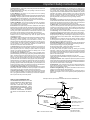
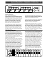
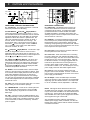
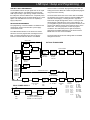
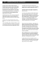
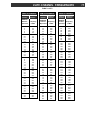
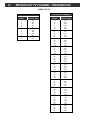
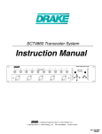
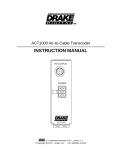
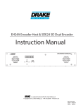
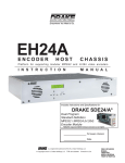
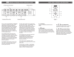
SCT3860 Transcoder System
Instruction Manual
TM
is a registered trademark of the R.L. Drake Company
© Copyright 2008 R.L. Drake Company
P/N: 3852383E-01-2008
2
Caution Statements
WARNING: TO PREVENT FIRE OR
ELECTRICAL SHOCK DO NOT
EXPOSE TO RAIN OR MOISTURE
A product and cart combination should be moved
with care. Quick stops, excessive force and
uneven surfaces may cause the product and cart
combination to overturn.
RISK OF ELECTRIC SHOCK
DO NOT OPEN
The lightning flash with arrow head symbol, within
an equilateral triangle, is intended to alert the user
to the presence of uninsulated "dangerous voltage"
within the product's enclosure that may be of
sufficient magnitude to constitute a risk of electric
shock to persons.
CAUTION: TO REDUCE THE RISK OF ELECTRIC
SHOCK,
DO NOT REMOVE COVER
NO USER-SERVICEABLE PARTS INSIDE
REFER SERVICING TO QUALIFIED PERSONNEL
The exclamation point within an equilateral triangle
is intended to alert the user to the presence of
important operating and maintenance (servicing)
instructions in the literature accompanying
the product.
CAUTION
WARNING: TO REDUCE THE RISK OF FIRE OR ELECTRIC SHOCK, DO NOT EXPOSE THIS PRODUCT
TO RAIN OR MOISTURE.
DO NOT OPEN THE CABINET, REFER SERVICING TO QUALIFIED PERSONNEL ONLY.
CAUTION: TO PREVENT ELECTRIC SHOCK, DO NOT USE THIS (POLARIZED) PLUG WITH AN EXTENSION
CORD RECEPTACLE OR OTHER OUTLET UNLESS THE BLADES CAN BE FULLY INSERTED TO
PREVENT BLADE EXPOSURE.
ATTENTION: POUR PREVENIR LES CHOCS ELECTRIQUES, NE PAS UTILISER CETTE FICHE POLARISEE
AVEC UN PROLONGATEUR, UNE PRISE DE COURANT OU UNE AUTRE SORTIE DE
COURANT, SAUF SI LES LAMES PEUVENT ETRE INSEREES A FOND SANS EN LAISSER
AUCUNE PARTIE A DECOUVERT.
Important Safety Instructions
1. Read Instructions—All the safety and operating instructions should be read
before the product is operated.
2. Retain Instructions—The safety and operating instructions should be
retained for future reference.
3. Heed Warnings—All warnings on the product and in the operating
instructions should be adhered to.
4. Follow Instructions—All operating and use instructions should be followed.
5. Cleaning—Unplug this product from the wall outlet before cleaning. Do not
use liquid cleaners or aerosol cleansers. Use a damp cloth for cleaning.
6. Attachments—Do not use attachments that are not recommended by the
product manufacturer as they may cause hazards.
7. Water and Moisture—Do not use this product near water—for example,
near a bathtub, wash bowl, kitchen sink or laundry tub; in a wet basement;
or near a swimming pool; and the like.
8. Accessories—Do not place this product on an unstable cart, stand, tripod,
bracket, or table. The product may fall, causing serious injury to a child or adult,
and serious damage to the product. Use only with a cart, stand, tripod, bracket,
or table recommended by the manufacturer, or sold with the product. Any
mounting of the product should follow the manufacturer's instructions, and
should use a mounting accessory recommended by the manufacturer.
9. A product and cart combination should be moved with care. Quick stops,
excessive force, and uneven surfaces may cause the product and cart
combination to overturn.
10. Ventilation—Slots and openings in the cabinet are provided for ventilation
and to ensure reliable operation of the product and to protect it from
overheating, and these openings must not be blocked or covered. The
openings should never be blocked by placing the product on a bed, sofa, rug,
or similar surface. This product should not be placed in a built-in installation
such as bookcase or rack unless proper ventilation is provided or the
manufacturer's instructions have been adhered to.
11. Power Sources—This product should be operated only from the type of
power source indicated on the marking label. If you are not sure of the type of
power supplied to your home, consult your product dealer or local power
company. For products intended to operate from battery power, or other
sources, refer to the operating instructions.
12. Grounding or Polarization—This product may be equipped with a
polarized alternating-current line plug (a plug having one blade wider than the
other). This plug will fit into the power outlet only one way. This is a safety
feature. If you are unable to insert the plug fully into the outlet, try reversing
the plug. If the plug should still fail to fit, contact your electrician to replace
your obsolete outlet. Do not defeat the safety purpose of the polarized plug.
Alternate Warnings—If this product is equipped with a three-wire groundingtype plug, a plug having a third (grounding) pin, the plug will only fit into a
grounding-type power outlet. This is a safety feature. If you are unable to insert
the plug into the outlet, contact your electrician to replace your obsolete outlet.
Do not defeat the safety purpose of the grounding-type plug.
12 a. Mise à la terre ou Polarisation—Cet appareil est équipé avec un cordon
d'alimentation à trois fils. Il est a brancher sur une prise ayant un connecteur a
la terre. Assurez-vous que la connection a la terre ne manque pas.
13. Power-Cord Protection—Power-supply cords should be routed so that
they are not likely to be walked on or pinched by items placed upon or against
them, paying particular attention to cords at plugs, convenience receptacles,
and the point where they exit from the product.
3
14. Outdoor Antenna Grounding—If an outside antenna or cable system is
connected to the product, be sure the antenna or cable system is grounded so
as to provide some protection against voltage surges and built-up static
charges. Article 810 of the National Electrical Code, ANSI/NFPA 70, provides
information with regard to proper grounding of the mast and supporting
structure, grounding of the lead-in wire to an antenna discharge unit, size of
grounding conductors, location of antenna-discharge unit, connection to
grounding electrodes, and requirements for the grounding electrode.
See Figure A.
15. Lightning—For added protection for this product during a lightning storm,
or when it is left unattended and unused for long periods of time, unplug it from
the wall outlet and disconnect the antenna or cable system. This will prevent
damage to the product due to lightning and power-line surges.
16. Power Lines—An outside antenna system should not be located in the
vicinity of overhead power lines, other electric light or power circuits, where it
can fall into such power lines or circuits. When installing an outside antenna
system, extreme care should be taken to keep from touching such power lines
or circuits as contact with them may be fatal.
17. Overloading—Do not overload wall outlets, extension cords, or integral
convenience receptacles as this can result in a risk of fire or electric shock.
18. Object and Liquid Entry—Never push objects of any kind into this product
through openings as they may touch dangerous voltage points or short-out
parts that could result in a fire or electric shock. Never spill liquid of any kind
on the product.
19. Servicing—Do not attempt to service this product yourself as opening
or removing covers may expose you to dangerous voltage or other hazards.
Refer all servicing to qualified service personnel.
20. Damage Requiring Service—Unplug this product from the wall outlet and
refer servicing to qualified service personnel under the following conditions:
a. When the power-supply cord or plug is damaged,
b. If liquid has been spilled, or objects have fallen into the product,
c. If the product has been exposed to rain or water,
d. If the product does not operate normally by following the operating
instructions. Adjust only those controls that are covered by the operating
instructions as an improper adjustment of other controls may result in damage
and will often require extensive work by a qualified technician to restore the
product to its normal operation,
e. If the product has been dropped or damaged in any way, and
f. When the product exhibits a distinct change in performance—this indicates
a need for service.
21. Replacement Parts—When replacement parts are required, be sure the
service technician has used replacement parts specified by the manufacturer
or have the same characteristics as the original part. Unauthorized substitutes
may result in fire, electric shock or other hazards.
22. Safety Check—Upon completion of any service or repairs to this product,
ask the service technician to perform safety checks to determine that the
product is in proper operating condition.
23. Wall or Ceiling Mounting—The product should be mounted to a wall or
ceiling only as recommended by the manufacturer.
24. Heat—The product should be situated away from heat sources such as
radiators, heat registers, stoves, or other products (including amplifiers) that
produce heat.
Figure A
Example of antenna grounding as per National Electrical Code, ANSI/NFPA 70
NOTE TO CATV SYSTEM INSTALLERS:
THIS REMINDER IS PROVIDED TO CALL THE
CATV SYSTEM INSTALLER'S ATTENTION TO
ARTICLE 820 - 40 OF THE NEC THAT
PROVIDES GUIDELINES FOR PROPER
GROUNDING AND, IN PARTICULAR, SPECIFIES THAT THE CABLE GROUND SHALL BE
CONNECTED TO THE
GROUNDING
SYSTEM OF THE BUILDING, AS CLOSE TO
THE POINT OF CABLE ENTRY AS PRACTICAL.
ANTENNA
LEAD IN
WIRE
GROUND CLAMP
ANTENNA
DISCHARGE UNIT
(NEC SECTION 810-20)
ELECTRIC
SERVICE
EQUIPMENT
GROUNDING CONDUCTORS
(NEC SECTION 810-21)
GROUND CLAMPS
NEC - NATIONAL ELECTRIC CODE
POWER SERVICE GROUNDING
ELECTRODE SYSTEM
(NEC ART 250, PART H)
4
Table of Contents / Specifications
TABLE OF CONTENTS
2
Caution Statements
3
Important Safety Instructions
4
Table of Contents / Specifications
5
General Description / Installation and Mounting
6
Controls and Connections
7
LNB Input / Setup and Programming
8
Setup and Programming (continued)
9
Additional Features
10 Additional Features (continued)
11 CATV Channel Frequencies Tables
12 Broadcast Channel Frequency Tables
13 Service / If You Need To Call For Help
14 Warranty
SPECIFICATIONS
SATELLITE INPUT
Frequency Range:
Tuning Increment:
Acquisition Range:
Input Level:
Input Impedance:
I/Q Phase Imbalance:
I/Q Amplitude Imbalance:
Mode:
FEC:
VITERBI Autoscan:
950 MHz to 2150 MHz.
500 kHz.
±5.0 MHz minimum.
-25 dBm to -70 dBm.
75 Ohms, return loss of 10 dB minimum.
<1 Degree.
<1dB.
QPSK, 8PSK.
DCII, DVB, advanced Turbo modes
1/2, 2/3, 3/4, 5/6, 6/7, 7/8 - DVB
5/11, 1/2, 3/5, 2/3, 3/4, 4/5, 5/6, 7/8 - DCII
Turbo QPSK modes: 1/2, 3/4, 2/3, 5/6, 7/8
Turbo 8PSK modes: 2/3, 5/6, 8/9, 3/4, 4/5
Input Data Rate: 2 Mbaud to 30 Mbaud.
QAM OUTPUT
Output Impedance:
Output Level:
Display Error:
Level Adjustment Increment:
Frequency Range:
Frequency Plan:
Broadband Spurious:
Broadband Noise:
Phase Noise:
Frequency Stability:
QAM I/Q Phase Error:
Channel Amplitude Error:
Carrier Suppression:
MER:
Mode:
Symbol Rate:
FEC:
75 Ohms, return loss of 10 dB minimum.
+ 25 to +40 dBmV, displayed.
± 2 dB maximum.
1 dB, nominal.
54 MHz to 864 MHz.
Standard, IRC, or HRC CATV channels
or off-air broadcast channels.
-60 dB, 5 MHz to 900 MHz.
-75 dBc, 6 MHz bandwidth.
-103 dBc/Hz @ 10 kHz offset.
± 5 kHz.
<1 degree.
<1 dB.
45 dB.
>40 dB, with blind equalizer.
16, 32, 64, 128, 256, 512, 1024 QAM.
1 Mbaud to 7 Mbaud.
ITU-T J.83 Annex A or Annex B.
RS232 CONTROL
Data Link: 4800 baud interface to PS151 via power
supply cable.
RS232 Input: DB-9 connector on PS151 for connection
to modem or PC.
RS232 Output: DB-9 connector on PS151 for connection
to additional transcoders.
GENERAL
Operating Temperature Range:
Size:
Weight:
Power Requirement:
00 C to +500 C, ambient.
1.1" W x 3.4" H x 13.25" D.
1 lb. 6 oz.
All voltages are provided by the Drake
model PS151 power supply. PS151
power requirement: 90 to 260 VAC / 150
W, maximum w. 10 transcoders powered.
Specifications subject to change without notice or obligation.
General Description / Installation and Mounting
5
DRAKE TRANSCODER SYSTEM
L BAND INPUTS
ID
1.1
12.45 dB
ENTER
GENERAL DESCRIPTION
The R.L. Drake model SCT3860 is a
professional quality, modular, digital headend component
providing QPSK or 8PSK input to QAM transmodulation
and RF upconversion functions in a single module. Up to
ten SCT3860 modules and a power supply module can
be accommodated in the RMT150 rack mounting tray,
occupying only a 2 unit (3.5”) high rack space. The
SCT3860 can transcode DigiCipher II or DVB digital
satellite signals, included those with advanced turbo
satellite FEC modes, outputting QAM modulation.
The transcoder then applies cable environment FEC to
this stream and remodulates using QAM modulation that
occupies a nominal 6 MHz wide cable channel slot. QAM
modes up through 1024QAM are supported.
The RF upconverter then upconverts the IF QAM signal to
the selected output channel - any standard EIA, IRC, or
HRC CATV channel or a broadcast off-air channel
frequency in the range of 54 to 860 MHz.
Bandpass flatness and phase noise are very closely
controlled in the SCT3860 to insure a high MER and S/N
ratio of the output signal. This insures that the transcoder
will not introduce a source of errors into the distribution
process. Because the MPEG2 transport stream information is not modified by the transcoder, all encryption,
authorization, and program guide information is passed
on to the CATV set top box, unchanged.
The SCT3860 accepts L band RF inputs between 950
and 2150 MHz from the LNB at the satellite dish. The
transcoder demodulates the selected satellite QPSK or
8PSK signal. The forward error correction (FEC) imbedded in the data stream is used to help retrieve an error
free digital transport stream containing the desired digital
programming multiplex.
INSTALLATION AND MOUNTING
Install the SCT3860 transcoders in the RMT150 rack
mounting frame. Slide each module into the tray so that
the "F" connector extends though the front panel hole, the
LED is properly aligned behind its front panel hole, and
the hook shaped projection on the bottom of the module
engages the rear of the mounting tray. Secure the
module with the supplied standard 1/2 inch "F" connector
mounting nut and nylon washer.
Connect the LNB signal to each SCT3860 module at the
front panel connector. Connect each SCT3860 RF output
"F" connector on the rear of the unit to the output combiner. The Drake model LBS2250 is a combination LNB
L band multiswitch/amplified splitter in addition to a CATV
output combiner. It provides these functions in only 1 RU
of rack space. Also, plug the cable from the front panel
fan module into the FAN POWER receptacle on the rear
of the power supply. Plug the line cord from the PS151
into the AC power source. SCT3860s can be mixed with
SCT1860s, SCT2860s, or SCT4860s and one PS151.
Similarly, mount the PS151 power supply in the RMT150
tray, making sure that the LCD display and control buttons
line up with their corresponding holes in the front panel,
and that the hook shaped projections on the rear of the
unit engage the rear of the mounting tray. Secure the
unit in place, with the supplied Philips head black
screws, from the front panel. Connect each SCT3860 to
the PS151 with the cable included with the SCT3860.
Each SCT3860 can connect to any one of the ten sockets
on the power supply. However, to minimize confusion, it
is suggested that the left most unit (as viewed from the
front panel) be connected to power supply socket
number 1, the second from the left to number 2, etc.
RS232 OUT
RS232 IN
+3
GND
RX
FAN POWER
100 - 240 VAC
47 - 63 HZ, 125 W
+12
+5
TX
1
2
3
4
5
6
7
8
9
10
RF OUTPUT
POWER
RF OUTPUT
POWER
RF OUTPUT
POWER
UNIT
SELECT
When installing the RMT150 tray of transcoders, it is not
necessary to leave a vertical airspace between the
transcoder tray and other equipment unless that other
equipment specifies that a space should be left open.
The air flow through the transcoders and power supply
has been designed to allow immediate adjacent
mounting of multiple RMT150 trays with SCT3860
transcoders and PS151 power supplies installed. Of
course, air spaces may be left in between RMT150s if
desired.
RF OUTPUT
RF OUTPUT
POWER
POWER
RF OUTPUT
POWER
RF OUTPUT
POWER
RF OUTPUT
POWER
RF OUTPUT
RF OUTPUT
POWER
POWER
6
Controls and Connections
DRAKE TRANSCODER SYSTEM
F1
F8
RS232 OUT
ID
1.1
12.45 dB
F7
R3
UNIT
SELECT
F2
F6
F5
F4
2
3
4
R2
RS232 IN
ENTER
1
F3
FRONT PANEL CONTROLS AND INDICATORS
F1 - LCD Display - This displays the PS151 or selected
transcoder parameter and its setting.
F2 -UNIT SELECT (Left) and (Right) Buttons These select either the PS151 power supply or one of
ten SCT3860 transcoders. Information from the selected
unit will be displayed on the LCD display for parameter
adjustment. When either button is pressed once, the
LED of the selected transcoder will blink for about 3
seconds, but the unit selected will not change. The
second press within 3 seconds will increment ( ) or
decrement ( ) to the next higher or lower numbered
unit. The PS151 power supply menu falls between
transcoder numbers 10 and 1.
F3 - (Left) and (Right) Buttons - Use the left or right
buttons to navigate from screen to screen to view a
parameter setting. This will not alter any settings. If in the
adjust mode, stop at the parameter you wish to adjust and
use the (up) and (down) buttons to adjust.
(Up) and (Down) Buttons - Use the up and
F4 down arrows to adjust a parameter value when in the
adjust mode. When not in the adjust mode, pressing the
(up) button will display the software version readout,
and pressing the (down) button will display the QAM
modulation output baud rate readout.
F5 - ENTER - Use the ENTER button to enter the adjust
mode or to save and load a new setting or settings. Hold
for 2 seconds until the display flashes to enter the adjust
mode. After adjustment using the up or down arrow
buttons, press again to save and load the new settings.
You may save one parameter at a time after it is adjusted
or wait until all adjustments are made and press to save
and load all at once.
F6 - FAN - One of five front panel cooling fans. To ensure
proper cooling, do not block these openings.
F7 - L BAND INPUTS - These are the L band inputs from
the LNB. The level must be between -70 and -25 dBm.
The L band frequency range will be in the 950 to 2150
MHz range.
F8 - LED - The LED on each SCT3860 will blink on and
off for approximately 3 seconds when that unit is selected.
When in the adjust mode, it will blink continuously. When
in the normal mode, it will be lit continuously whenever
power is applied.
RF OUTPUT
R1
+3
GND
RX
FAN POWER
100 - 240 VAC
47 - 63 HZ, 125 W
+12
+5
TX
5
6
7
8
9
10
R4
R6
POWER
R5
REAR PANEL CONNECTIONS
R1 - RS232 OUT - This RS232 serial connector can
connect to the RS232 IN connector on another rack
containing a PS150, PS151, or PS100 power supply
(included transcoders could be SCT860, SCT1860,
SCT2860, SCT3860 or SCT4860 transcoders), thus
allowing computer control of multiple racks of these units
with the same PC connection.
R2 - RS232 IN - Connecting this RS232 serial connector
to the serial port of a personal computer equipped with
Drake RS232 remote control software, allows remote
monitoring and programming of each transcoder. Alternatively, can be connected to the Drake SCTeci. No connection is required for front panel control.
R3 - Fan Power- Connect the two conductor cable from
the front panel fans to this connector.
R4 - Power Out - These connectors are for connecting
the power cables from each individual SCT3860 to the
PS151 power supply. The other end of each cable can be
plugged into any one of the ten transcoders. However,
to minimize confusion, it is strongly suggested that the
left most unit (as viewed from the front panel) be connected to power supply socket number 1, the second
from the left to number 2, etc. Do not attempt to use any
power supply other than this Drake supplied model.
R5 - Power In - This connector supplies power and
program control to the SCT3860. Connect a cable from
this connector to the appropriate connector on the PS151
power supply (see R4 above).
R6 - RF Output - This is the QAM output channel RF
output. The frequency range is between 54 and 864 MHz
depending upon the channel selected. The output level
is +25 to +40 dBmV, nominal, adjustable in 1 dB steps.
NOTE: Although the above discussions refer to the
SCT3860 transcoder modules, other Drake transcoders
may be mixed with SCT3860s in the same RMT150 rack
mounting tray. These include the SCT1860, SCT2860,
and SCT4860. The PS151 power supply/control module
will recognize each type of transcoder.
Also, SCT860 transcoders, although controlled by a
different power supply model, the PS100, can have the
RS232 control 'daisy chained' with the PS150 and PS151
controlled transcoders.
LNB Input / Setup and Programming 7
LNB INPUT AND LNB POWERING
The SCT3860 receives its input signal from the IF output
of the LNB located on the satellite dish. Because this
LNB output usually is split among multiple transcoders,
the LNB power must be obtained from a separate power
inserter and supply that is connected ahead of an L band
splitter. The SCT3860 does not have the capability to
supply LNB power.
remote control is connected, all programming other than the
setting of the PS151 RACK ID number and password programming can be done remotely.
The chart below shows each of the menus that are available
for parameter set up and/or viewing for both SCT3860s and
the PS151 Power Supply. Pressing the left or right arrow
buttons will navigate through these menus. You may do this
without danger of disturbing any of the current settings. As
you navigate through the menus, the parameter is listed on the
top line of the display and the current setting is shown on the
bottom line. For set up purposes, it is best to progress
clockwise in the chart below (use the right arrow button),
starting from the RS232 adjustment on the PS151 and the
MODE menu for each of the SCT3860s.
SETUP AND PROGRAMMING
The programming of each SCT3860 in an RMT150 rack
mounting tray is done from the PS151 power supply
mounted in that rack.
The UNIT SELECT buttons on the PS151 are used to
select the unit to be programmed, including the PS151
itself. The actual programming is done via the five
buttons on the left side of the PS151. If the RS232
The charts below show all of the settings that are available
through these menus.
DSS or DVB
SCT3860 TRANSCODER
HITS:
1, 2, ....16
MODE:
G10:
DCII
HITS
G10
DISHScan
TURBO
DVB
DSS
7, 9, 12
QPSK 1/2
QPSK 3/4
8PSK 2/3
8PSK 4/5
QPSK 5/6
QPSK 7/8
8PSK 5/6
8PSK 8/9
8PSK 3/4
QPSK 2/3
2400
4800
9600
19200
DVB or TURBO
DUAL POL
STACKED
DCII:
IF FREQ:
BD RATE:
RN - FADE
ENCODER:
ENCODER:
Select
desired freq.
950.0 to
2150.0 MHz
Select to match
transmitted
symbol rate.
Example:
19.510 M
ENABLED
DISABLED
ITU - A
ITU - B
DAVIC
DVB
OUTPUT:
INTERLV:
NORMAL
Select only
if ITU-B
is selected.
(ITU-A only)
COMBINED
SPLIT - Q
SPLIT - I
TURBO:
DISHScan Mode Only
IF FREQ:
Select
desired freq.
950.0 to 2150 MHz
LBS:
CHANNEL:
CHANNEL
PLAN:
RF OUT:
A
B
Select EIA
output channel
2 - 135
OFF AIR
CATV
IRC
HRC
Select level
25 - 40 dBmV
PS151 POWER SUPPLY
RS232:
LNB:
LBS A
xxxxxxxx
LBS B
yyyyyyyy
xxxxxxxx & yyyyyyyy
assignable via RS232 by PC only.
CD ROM V2.7 or above required.
RACK ID:
Select desired
rack ID number.
0-7
STANDBY
CW
I128, J1
I128, J2
I64, J2
I128, J3
I132, J4
I128, J4
I16, J8
I128, J5
I8, J16
I128, J6
I4, J32
I128, J7
I2, J64
I128, J8
I1, J128
MODULAT:
Select for
ITU - A:
16 -QAM
32 - QAM
64 - QAM
128 - QAM
256 - QAM
512 - QAM
1024 - QAM
ITU - B:
64 - QAM
256 - QAM
1024 - QAM
8
Setup and Programming (continued)
To adjust /set a parameter(s), enter the adjust mode by
pressing the center "ENTER" button for several seconds
until the display begins to flash. You are now in the adjust
mode and the up and down buttons will take you through
the various parameters. Find the desired setting and then
use the right arrow to progress to the next menu. After
setting all parameters in all menus, press the "ENTER"
button once. This will load the settings and save them in
memory.
Pressing the left or right UNIT SELECT button will also
load the settings and save them in memory , just as would
pressing the "ENTER" button, in addition to moving to an
adjacent transcoder.
Note that many of the parameters will not be changed
until the "ENTER" button is pressed. These include:
MODE related settings, LNB type, IF FREQ, BD RATE,
ENCODER, MODULATE, and INTERLV. If you need to
see the result of a change right away for these
parameters, press the "ENTER" button to load and store
the new parameter setting and then you can reenter the
adjust mode by pressing the "ENTER" button again for
several seconds. The RACK ID, RS232, OUTPUT, RF
OUT level, and CHANNEL (output) settings will all change
immediately as soon as they are adjusted.
PRESETS FOR HITS
The SCT3860 provides factory loaded presets for HITS.
When a preset is selected and entered, all of the
operating parameters for the satellite tuner, demodulator
and for the QAM modulator are set to the preset settings.
You will then need to set only the output channel and
level and LNB related parameters. Note that selecting
and entering the HITS options in the mode menu,
changes any other parameters that might have been
adjusted previously to the preset values. If you do not
wish to use presets, be sure that you have chosen the
DCII selection before pressing the enter button to load
and save the values.
T
SCT3860 QUICK START for HITS - Front Panel Control
1)Connect cables from LNB, to output combiner, and to
PS151 power supply.
2)Plug PS151 AC line cord into power source.
3)Use the Unit Select (Left) and (Right) buttons to
select the PS151 power supply.
4) Push ENTER button on PS151 for 2 seconds until
display flashes to enter adjust mode.
5)Use the Unit Select (Left) or (Right) buttons to
select RS232.
6) Use (Up) or (Down) buttons to set to 4800
unless another rate is indicated when setting up a modem
interface. Press ENTER to save this setting.
7)Use the Unit Select (Left) and (Right) buttons to
select the desired SCT3860.
8) Push ENTER button on PS151 for 2 seconds until
display flashes to enter adjust mode.
9) (Left) arrow - CHANNEL menu - Use the (Up)
or (Down) arrow buttons to select the desired EIA
CATV output channel for this program multiplex.
(Right) arrow - MODE menu - Up or Down arrows
10)
to select HITS.
(Right) arrow - HITS menu. Up or Down arrows
11)
to select the desired multiplex corresponding to the EIA
output channel that you set in step 9. This correlation is
determined by the channel map used for your installation.
12)
(Right) arrow - LNB menu - Up or Down arrows STACKED or DUAL POL - Set to the type you are using.
13) ENTER - Push once to store and load all of the above
settings.
By selecting the HITS mode in step 10, instead of the
generic DCII setting, many of the other adjustable parameters have been preset to the values required for these
networks, determined by the preset programming in the
SCT3860. If you reenter the adjust mode later and make
changes to the preset parameters or if you altered any of
the parameters that were preset during the steps above
such that the values do not match the preset values, the
display in the mode menu will revert to DCII.
If the dish has been aimed, you should now see a SN
readout on the display. If it is less than 7 dB, the transcoder
will not stay locked to the satellite signal. If the SN reading
is showing only around 2 dB, you likely are not pointed at
the correct satellite or the dish is not peaked. For reliable
operation, the SN level should be above 10 dB and preferably even higher. The better the margin above the approximately 7 dB threshold, the less likely you will encounter
drop outs due to thunderstorms or snow storms.
NOTE: If you are using the RS232 remote control program,
all of the above adjustments may be made via the PC,
except the RACK ID assignment for the PS151 module.
DISH NETWORK AUTO SET
When the using the SCT3860 for DISH Network, select
DISHScan from the MODE menu. Next, in the IF FREQ
menu, select the IF frequency that corresponds to the DISH
Network transponder that is desired. You will then advance all the way to the OUTPUT menu as the SCT3860
will automatically search for and set the satellite symbol
rate and FEC. Based on what is found, the SCT3860 will
then automatically select the proper QAM encoding, QAM
modulation level, Interleave, etc. Finally, set the desired
output level and EIA channel in the appropriate menus.
If the modulation on a particular transponder is changed by
DISH in the future, the SCT3860 will automatically
reacquire the new signal, assuming it's on the same
frequency, and automatically set the various satellite
demodulator and QAM modulator parameters.
Using the presets will significantly shorten the set up time
for a new headend. These preset settings can be altered at
any time if the required parameters change in the future.
Whenever DISHScan is selected, the rain fade logic is
automatically enabled.
TURBO FEC
Some advanced satellite FEC modes may be selected
under the TURBO menu.
Additional Features
OUTPUT LEVEL
The SCT3860 provides a +40 dBmV QAM output level that
is desirable when transcoders are combined with analog
modulators that have +45 dBmV output level. The
SCT3860 output level can be turned down as much as
15 dB if a lower level is desired. Each SCT3860’s RF
output level can be read out on the PS151 power supply
LCD when that unit is selected, or via the RS232 remote
connection.
Because some operators may not have test equipment
designed to measure QAM power levels, and analog
meters may be grossly inaccurate if a QAM signal is read,
the SCT3860 has a CW output mode that can be useful
for measuring/adjusting the output level of the transcoder
with any meter that measures CW carrier power. A
special QAM instrument is not required. No input signal is
required for this measurement. The CW carrier power is
equal to the QAM power level that will result when the unit
is returned to a normal QAM modulation mode.
IMPORTANT NOTE: When the SCT3860 is placed in the
continuous wave (CW) mode, the output carrier frequency
will be at the center of the output channel. It will not be
located at the NTSC video carrier frequency. Adjust test
equipment accordingly to obtain an accurate result.
The PC control software allows all transcoders to be
easily switched to the CW mode at one time for set up
purposes. After any level tweaks are made, they can all
be switched back to normal mode at one time. It is also
possible to individually select a single transcoder to be
switched to the CW mode, if desired. In a typical leveling
process, the output of the headend is monitored after the
final combiner and all analog channel levels are set to the
desired level. Then, with the SCT3860s all set for CW
output, the SCT3860 CW carrier levels can be all
tweaked to a desired level (usually 6 to 10 dB) below the
analog video carrier levels. When switched back to
normal mode, the SCT3860s will all be outputting QAM
channel powers equal to the CW powers set up.
RAIN FADE LOGIC
When the rain fade feature is enabled, the transcoder will
mute its RF output whenever the input S/N drops below a
usual level. This logic is always enabled in the
DISHScan mode.
STANDBY MODE
The SCT3860 has a standby output mode which turns off
the RF output. This can be used when it is desirable to
keep a backup unit on line. The standby mode can be
selected via the OUTPUT menu.
9
POWER SUPPLY
The SCT3860 requires multiple power supply voltages
that are all obtained from the Drake model PS151 power
supply module. The PS151 mounts in the RMT150 rack
tray along with one to ten SCT3860 (or other similar
Drake models) transcoders. The PS151 buffers and
distributes the RS232 remote control data from its DB9,
RS232 INPUT connector to up to ten transcoders and to
the DB9, RS232 OUTPUT connector. Multiple PS151s
can be ‘daisy chained’ via the DB9 INPUT and OUTPUT
connectors to allow control of up to 70 transcoder
modules with a single connection to a PC.
The PS151 operates over a wide range of AC input
voltages from 90 VAC to 264 VAC. The USA version has
an attached 3 wire line cord. Power consumption from the
AC line will be around 150 W maximum with ten
transcoders installed. In many cases, the power will below
this level.
RS232 REMOTE CONTROL AND MONITORING
The SCT3860 provides for remote control and/or
monitoring of all transcoder parameter settings. It is
possible to view all of the current parameter settings
including the output level setting for each transcoder. It is
also possible to remotely monitor the SNR level and the
baud rate. The LBS2250 settings may monitored or
changed. The transcoder parameter settings may be
uploaded to a PC file for saving on the PC or a new
parameter configuration from the PC file can be downloaded to the SCT3860. A single parameter may be
adjusted if desired. It is possible to put all transcoders in
or out of CW mode with a single command. A unit may
be placed in or taken out of the standby mode. A
password can be assigned to prevent unauthorized
changes to parameter settings but the present settings
can be read out remotely without entering the password.
Further details on the RS232 control program are
provided with the instructions included with the CDROM
containing the control program (shipped with your PS151
power supply).
The previously described remote interface is accomplished by connecting an RS232 interface cable between
the PS151 power supply DB9 INPUT connector and a PC
serial port. The required program is supplied by Drake
with the PS151 power supply. This setup will allow
RS232 interfacing to up to ten SCT3860 transcoders
connected to the PS151. When more than one tray of
transcoders is used, the OUTPUT DB9 connector on the
PS151 can be used to link to a second PS151 as well as
a PS150 (SCT1860s) or a PS100 (SCT860s) in the same
headend. Use a DB9 to DB9 RS232 jumper cable from
the OUTPUT of the first supply to the INPUT of the
second supply. You can extend this to additional supplies
as long as the total number of PS151s to control does not
exceed 7 (70 SCT1860/2860/3860/4860s) and the
number of SCT860s does not exceed 64.
10
Additional Features (continued)
In order for the PC software to identify the proper
SCT3860 to which you wish to connect, each SCT3860
must be assigned a unit ID number. The unit ID number
consists of the rack number, a dash, and the number of
the unit in a given rack. For example, the third unit
(plugged into power socket numbered 3) in rack number
one would have a unit ID number of "1-3", and the tenth
unit in rack number three would have a unit number of "310". The number of each unit in a given rack is determined by the connector number on the PS151 power
supply to which it is connected.
Programming the rack number is easily accomplished by
using the PS151 "RACK ID:" menu and setting the ID
number with the PS151 front panel set up buttons. If no
RS232 control is desired, this RACK ID number should be
set to 0.
The PS151 will not respond to RS232 activity when its
RACK ID is 0. Any number of PS151s can have a rack ID
of 0.
When using RS232, assign a unique ID, between 1-1 and
7-10, for each SCT3860 to be controlled. Do not duplicate
a number among any of the up to 70 transcoders that are
to be connected through the same RS232 path to the PC.
This RS232 connection can be used by directly
connecting to a PC serial port or remotely by interfacing
through modems. If an auto answer modem is used at the
headend, one can interface via telephone connection.
The RS232 connection can be used to download new
operating firmware to the SCT3860, if needed for use
with future options.
For remote control operation, PS150/SCT1860 systems
and/or PS100/SCT860 systems can be “daisy chained”
with PS151/SCT2860s, SCT3860s, and SCT4860s, if
desired, and can be controlled by the same PC using the
Drake supplied software. A maximum of 64 SCT860s
can be connected in this fashion in addition to the
maximum of 70 SCT1860/2860/3860/4860s. Any
combination of PS100s, PS150s, and PS151s can be
connected in this manner as long as the maximum
numbers indicated above are not exceeded.
Using the SCTs with the LBS2250 L Band Splitter: The
LBS2250 unit should be mounted above the RMT150
with no extra space between the units. One or two LNB, L
band inputs in the range of 950 to 2250 MHz may be
connected to the inputs of the LBS. On the front panel
side of the rack, the LNB inputs of each SCT should be
connected with a short coaxial jumper cable to the output
of the LBS that is directly above it. Then the power supply
cable of any one of the transcoders should be 'looped
through' the LBS2250.
When a LBS2250 has been connected as described in
the previous paragraph, a new menu will appear in the
SCT menu chain, between the MODE and CHANNEL
menus (see chart). This is where the user may select the
setting of the LNB input switch for that transcoder - either
LNB input A or LNB input B may be selected.
An eight character name such as 'DISH 110' can be
programmed for the A setting and the B setting so that the
setting is more meaning if monitored remotely. This name
may be programmed only via the RS232 remote program
using version 2.7 or above CDROM.
CATV CHANNEL FREQUENCIES
TABLE 1: CATV
CABLE TV CHANNELS
CABLE TV CHANNELS
CABLE TV CHANNELS
Channel
Number
Center of
Channel
Channel
Number
Center of
Channel
Channel
Number
Center of
Channel
EIA/NCTA
Numeric
Equivalent
Frequency
in MHz
EIA/NCTA
Numeric
Equivalent
Frequency
in MHz
EIA/NCTA
Numeric
Equivalent
Frequency
in MHz
2
3
4
5
6
95
96
97
98
99
14
15
16
17
18
19
20
21
22
7
8
9
10
11
12
13
23
24
25
26
27
28
29
30
31
32
33
34
35
36
37
38
39
40
57
63
69
79
85
93
99
105
111
117
123
129
135
141
147
153
159
165
171
177
183
189
195
201
207
213
219
225
231
237
243
249
255
261
267
273
279
285
291
297
303
309
315
321
41
42
43
44
45
46
47
48
49
50
51
52
53
54
55
56
57
58
59
60
61
62
63
64
65
66
67
68
69
70
71
72
73
74
75
76
77
78
79
80
81
82
83
84
85
327
333
339
345
351
357
363
369
375
381
387
393
399
405
411
417
423
429
435
441
447
453
459
465
471
477
483
489
495
501
507
513
519
525
531
537
543
549
555
561
567
573
579
585
591
86
87
88
89
90
91
92
93
94
100
101
102
103
104
105
106
107
108
109
110
111
112
113
114
115
116
117
118
119
120
121
122
123
124
125
126
127
128
129
130
131
132
133
134
135
597
603
609
615
621
627
633
639
645
651
657
663
669
675
681
687
693
699
705
711
717
723
729
735
741
747
753
759
765
771
777
783
789
795
801
807
813
819
825
831
837
843
849
855
861
11
12
BROADCAST TV CHANNEL FREQUENCIES
TABLE 2: BC TV
VHF BROADCAST CHANNELS
Channel
Number
2
3
4
5
6
7
8
9
10
11
12
13
Center of Channel
Frequency (MHz)
57
63
69
79
85
177
183
189
195
201
207
213
UHF BROADCAST CHANNELS
Channel
Number
14
15
16
17
18
19
20
21
22
23
24
25
26
27
28
29
30
31
32
33
34
35
36
37
38
39
40
41
42
43
44
45
46
47
48
49
50
51
52
53
54
55
56
57
58
59
60
61
62
63
64
65
66
67
68
69
Center of Channel
Frequency (MHz)
473
479
485
491
497
503
509
515
521
527
533
539
545
551
557
563
569
575
581
587
593
599
605
611
617
623
629
635
641
647
653
659
665
671
677
683
689
695
701
707
713
719
725
731
737
743
749
755
761
767
773
779
785
791
797
803
Service / If You Need To Call For Help
SERVICE INFORMATION
You may contact the R.L. DRAKE Service Department for
additional information or assistance by calling
+1 (937) 746-6990, Monday through Friday, between
8:00 A.M. and 4:00 P.M. Eastern Time, except on holidays.
You may also contact the R.L. DRAKE Service Department by
E-mail at the following address:
[email protected]
or by Telefax:
+1 (937) 806-1576.
IF YOU NEED TO CALL FOR HELP
Call our Customer Service/Technical Support line at
+1 (937) 746-6990 between 8:00 A.M. and 4:00 P.M.
Eastern Time, weekdays. Please have the unit’s serial
number available. We will also need to know the specifics
of any other equipment connected to the unit.
When calling, please have the unit up and running, near
the phone if possible. Our technician(s) will likely ask
certain questions to aid in diagnosis of the problem. Also,
have a voltmeter handy, if possible.
R.L. DRAKE also provides technical assistance by
e-mail: [email protected]
or by Telefax: +1 (937) 806-1576.
Many of the products that are sent to us for repair are in
perfect working order when we receive them. For these
units, there is a standard checkout fee that you will be
charged. Please perform whatever steps are applicable
from the installation sections of the Owner's Manual
before calling or writing—this could save unnecessary
phone charges. Please do not return the unit without
contacting R.L. DRAKE first: it is preferred to help troubleshoot the problem over the phone (or by mail) first, saving
you both time and money.
Inside the carton, enclose a note with your name, address, daytime phone number, and a description of the
unit’s problem.
The unit must be sent to the following address:
Service Department
R.L. DRAKE COMPANY
230 Industrial Drive
Franklin, Ohio 45005 U.S.A.
Be sure to include your street address which will be
needed for UPS return. UPS Surface (Brown Label) takes
7-10 days to reach us depending on your location, Blue
takes 2-3 days.
13
Should you want to return your unit for service, package
the unit carefully using the original carton or other suitable
container.
Write your return address clearly on the shipping carton
and on an enclosed cover letter describing the service
required, symptoms or problems. Also include your
daytime telephone number and a copy of your proof of
purchase.
The unit will be serviced under the terms of the
R.L. DRAKE COMPANY Limited Warranty and returned
to you.
Red is an overnight service. Send the unit in a way that it
can be traced if we can’t verify receipt of shipment. We
suggest UPS or insured postal shipment.
If the unit is still under the original owner’s warranty,
R.L. DRAKE will pay the cost of the return shipment to
you. Our return shipping policy is that we will return it UPS
Brown if received Brown or by US Mail, it will be returned
Blue if received Blue or Red—or it will be returned
however you prefer if you furnish the return cost for the
method you select.
If the unit is out of warranty, use one of the following
methods for return shipment:
1) You designate billing to American ExPress, VISA,
MasterCard or Discover card;
2) You prepay the service charges with a personal check,
or
3) You specify some other method of return and payment.
When calling, the technician can estimate the repair
charges for you over the phone. This is another good
reason to call before sending a unit in for repair.
Typically, equipment is repaired in five to ten working days
after it arrives at R.L. DRAKE if we have all the facts. If we
must call you, it may take longer. R.L. DRAKE is not
responsible for damage caused by lightning, nonprofessional alterations, “acts of God”, shipping damage, poor
storage/handling, etc. R.L. DRAKE will make note of any
shipping damage upon receipt.
You will need to send proof of purchase to receive
warranty service. Typically, a copy of the invoice from an
R.L. DRAKE dealer will suffice. The warranty is for the
original owner only and is not transferable.
14
Warranty
Three Year Limited Warranty
R.L. DRAKE COMPANY warrants to the original purchaser this product shall be free from defects in material or
workmanship for three (3) years from the date of original purchase.
During the warranty period the R.L. DRAKE COMPANY or an authorized Drake service facility will provide, free of
charge, both parts and labor necessary to correct defects in material and workmanship. At its option,
R.L. DRAKE COMPANY may replace a defective unit.
To obtain such a warranty service, the original purchaser must:
(1) Retain invoice or original proof of purchase to establish the start of the warranty period.
(2) Notify the R.L. DRAKE COMPANY or the nearest authorized service facility, as soon as possible after discovery
of a possible defect, of:
(a) the model and serial number,
(b) the identity of the seller and the approximate date of purchase; and
(c) A detailed description of the problem, including details on the electrical connection to associated equipment and the
list of such equipment.
(3) Deliver the product to the R.L. DRAKE COMPANY or the nearest authorized service facility, or ship the same in its
original container or equivalent, fully insured and shipping charges prepaid.
Correct maintenance, repair, and use are important to obtain proper performance from this product. Therefore carefully
read the Instruction Manual. This warranty does not apply to any defect that R.L. DRAKE COMPANY determines is
due to:
(1) Improper maintenance or repair, including the installation of parts or accessories that do not conform to the quality
and specifications of the original parts.
(2) Misuse, abuse, neglect or improper installation.
(3) Accidental or intentional damage.
All implied warranties, if any, including warranties of merchantability and fitness for a particular purpose, terminate
three (3) years from the date of the original purchase.
The foregoing constitutes R.L. DRAKE COMPANY’S entire obligation with respect to this product, and the original
purchaser shall have no other remedy and no claim for incidental or consequential damages, losses or expenses. Some
states do not allow limitations on how long an implied warranty lasts or do not allow the exclusions or limitation of
incidental or consequential damages, so the above limitation and exclusion may not apply to you.
This warranty gives you specific legal rights and you may also have other rights which vary from state to state.
This warranty shall be construed under the laws of Ohio.
For Service, contact:
R.L. DRAKE COMPANY
230 Industrial Drive
Franklin, Ohio 45005 U.S.A.
Customer Service and Parts Telephone: +1 (937) 746-6990
Telefax: +1 (937) 806-1576
World Wide Web Site: http://www.rldrake.com
R.L. Drake Company
230 Industrial Drive
Franklin, Ohio 45005 U.S.A.
Customer Service and Parts Telephone: +1 (937) 746-6990
Telefax: +1 (937) 806-1576
World Wide Web Site: http://www.rldrake.com