1
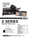
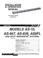
INSTALLATION
& OPERATION
MANUAL
AS-10/AS-847/AS-839
ARROWSTIK
®
MODELS AS-10,
AS-847, AS-839, AS6FL
AND SPLIT ARROWSTIK® SYSTEMS
Contents:
Introduction (with warnings) .................................................... 2
Unpacking & Pre-installation .................................................... 2
Installation & Mounting ............................................................. 2
Permanent Mounting ............................................................... 2
On Code 3® LP 6000TM Series Frame .................................... 3
On Code 3® XL 5000TM Series Frame .................................... 3
Wiring Instructions .................................................................... 6
Operations ................................................................................ 6
Options & Specifications ........................................................... 7
Maintenance ............................................................................. 7
Changing the Lamps & Optic Filters ......................................... 8
Trouble Shooting Guide ............................................................ 8
Parts List (Replacement parts / Exploded View) ................. 9-10
Notes....................................................................................... 11
Warranty ................................................................................. 12
all instructions and warnings before installing and using.
IMPORTANT: Read
INSTALLER: This manual must be delivered to the end user of this equipment.
Introduction
The ArrowStik® is a traffic directing device that will mount in many locations including the back of a lightbar or
rear panel of a truck. The ArrowStik is a series of lights that point traffic away from the scene of an accident or
work site.
The ArrowStik uses standard 1156 incandescent lamps for operation. The lamp and reflector assembly are
mounted into the sliding track of the painted aluminum extrusion for easy maintanence.
The ArrowStik control box delivers four (4) distinct warning patterns: arrow left, arrow right, center out, and
alternating flash. An Arrowstik controller with fast speed, night light dimming, and an auxiliary 12 amp switched
output is also available.
The ArrowStik draws a maximum of twenty (20) amps during its cycle, while averaging less than ten (10) amps.
!
WARNING!
The use of this or any warning device does not insure that all drivers can or will observe or react
to an emergency warning signal. Never take the right-of-way for granted. It is your
responsibility to be sure you can proceed safely before entering an intersection, driving against
traffic, responding at a high rate of speed, or walking on or around traffic lanes.
The effectiveness of this warning device is highly dependent upon correct mounting and wiring.
Read and follow the manufacturer’s instructions before installing or using this device. The
vehicle operator should insure daily that all features of the device operate correctly. In use,
the vehicle operator should insure the projection of the warning signal is not blocked by vehicle
components (i.e.: open trunks or compartment doors), people, vehicles, or other obstructions.
This equipment is intended for use by authorized personnel only. It is the user’s responsibility
to understand and obey all laws regarding emergency warning devices. The user should
check all applicable city, state and federal laws and regulations.
Public Safety Equipment, Inc., assumes no liability for any loss resulting from the use of this
warning device.
Proper installation is vital to the performance of this warning device and the safe operation of
the emergency vehicle. It is important to recognize that the operator of the emergency vehicle
is under psychological and physiological stress caused by the emergency situation. The
warning device should be installed in such a manner as to: A) Not reduce the output
performance of the system, B) Place the controls within convenient reach of the operator so
that he can operate the system without losing eye contact with the roadway.
Emergency warning devices often require high electrical voltages and/or currents. Properly
protect and use caution around live electrical connections. Grounding or shorting of electrical
connections can cause high current arcing, which can cause personal injury and/or severe
vehicle damage, including fire.
PROPER INSTALLATION COMBINED WITH OPERATOR TRAINING IN THE PROPER USE
OF EMERGENCY WARNING DEVICES IS ESSENTIAL TO INSURE THE SAFETY OF
EMERGENCY PERSONNEL AND THE PUBLIC.
Unpacking & Pre-installation
After unpacking the items, carefully inspect the unit and its associated parts for any damage that may have
been caused in transit. Report any damage to the carrier immediately.
Installation & Mounting
The ArrowStik was designed with a flexible mounting system to allow its use with as many lightbars as possible.
The following installation instructions provide direction for mounting the ArrowStik to the Code 3® XL 5000TM
Series and LP 6000TM Series Lightbar frames. Information is given, however, that mounting on other lightbar
systems should be possible. Questions about a specific application should be directed to the Technical Hotline
number given on the last page of this manual.
Permanent Mounting
Prior to mounting, consideration must be given to cable location and lamp replacement. The cable should
exit the endcap on the driver's side unless otherwise specified. Lamp replacement requires 48" of clearance
on the cable side to remove the light head assembly.
2
LP 6000TM Series Frame:
1)
2)
3)
4)
5)
6)
7)
8)
If an LP lightbar is currently mounted on the vehicle, remove the lightbar from the vehicle roof and turn
it upside down. Rest it on cloth or some other soft surface. It is not necessary to disconnect the wiring.
Determine whether you have an early or late model LP 6000™ Series frame. Early models are fairly
smooth along the bottom (Figure 2). Late models have a depressed trough in the center of the base.
(Figure 3).
Mount the ArrowStik® bracket on the front or rear of the LP 6000 Series frame as desired. If you have
an early model LP frame, refer to Figure 2. If you have a late model LP frame, use of the plastic shims
supplied in the parts bag will ensure level mounting of the ArrowStik
(refer to Figure 3). In either case, leave the mounting bolts loose until step 7.
Turn the lightbar right side up and attach the ArrowStik to its mounting bracket as shown in Figure 4.
Leave the mounting bolts loose so the ArrowStik can be moved from side to side.
Put the lightbar on the vehicle roof making sure not to scratch the vehicle. Check for clearance below
the lightbar as you proceed.
Reposition the lightbar and secure it to the vehicle.
Tighten the bolts that hold the ArrowStik mounting bracket to the lightbar, checking that the brackets
are aligned with each other.
Position the ArrowStik in the center of the vehicle and tighten the bolts that hold it to the mounting
bracket.
5 "
16
5 "
16
5 "
16
MOUNTING BOLT
5 "
16
MOUNTING BOLT
FLAT WASHER
FLAT WASHER
MOUNTING BRACKET
MOUNTING BRACKET
PLASTIC SHIMS
FIGURE 3
LP 6000 SERIES
(LATE MODEL)
FIGURE 2
LP 6000 SERIES
(EARLY MODEL)
MOUNTING BRACKET
¼" SPLIT WASHER
¼" ACORN NUT
FIGURE 4
XL 5000
1)
2)
3)
4)
5)
6)
TM
Series Frame:
If an XL Series Lightbar is already mounted on the vehicle,remove the speaker cover and then the lens
from one end of the lightbar by removing the six (6) screws holding it in place. Figure 5 illustrates three
of the screws on one side.
Remove the lightbar from the vehicle roof and turn it upside down. Rest it on cloth or some other smooth
surface. It is not necessary to disconnect the wiring.
At the same end, mark the location of the "U" bracket assembly on the lightbar frame (see Figure 5).
Remove the "U" bracket assembly by loosening the nuts and sliding it off the lightbar base.
If the ArrowStik is to be front mounted, slide the two carriage bolts into the front groove as shown in
Figure 6. Otherwise, slide both carriage bolts into the rear groove.
Re-secure the "U" bracket assembly in the position marked in Step 3 and replace the lens.
3
Loosely mount the ArrowStik® bracket to the lightbar as shown in Figure 6.
Loosely mount the ArrowStik to the bracket as shown in Figure 4.
Put the lightbar on the vehicle roof making sure not to scratch the vehicle. Check for clearance below
the lightbar as you proceed.
10) Reposition the lightbar and secure it to the vehicle.
11) Tighten the bolts that hold the ArrowStik mounting bracket to the lightbar, checking that they are in the
same position front to back with respect to the mounting bracket.
12) Position the Arrowstik in the center of the vehicle and tighten the bolts that hold it to the mounting bracket.
7)
8)
9)
5 "
16
ACORN NUT
PLASTIC SHIM
MOUNTING BRACKET
U-BRACKET
ASSEMBLY
FIGURE 5
XL 5000 SERIES
5 "
16
FIGURE 6
XL 5000 SERIES
Wiring Instructions
!
WARNING!
Note:
CARRIAGE
BOLT
Larger wires and tight connections will provide longer service life for components. For high
current wires it is highly recommended that terminal blocks or soldered connections be used
with shrink tubing to protect the connections. Do not use insulation displacement connectors
(e.g. 3M® Scotchlock type connectors). Route wiring using grommets and sealant when
passing through compartment walls. Minimize the number of splices to reduce voltage drop.
High ambient temperatures (e.g. underhood) will significantly reduce the current carrying
capacity of wires, fuses, and circuit breakers. Use "SXL" type wire in engine compartment.
All wiring should conform to the minimum wire size and other recommendations of the
manufacturer and be protected from moving parts and hot surfaces. Looms, grommets, cable
ties, and similar installation hardware should be used to anchor and protect all wiring.
Fuses or circuit breakers should be located as close to the power takeoff points as possible
and properly sized to protect the wiring and devices.
Particular attention should be paid to the location and method of making electrical connections
and splices to protect these points from corrosion and loss of conductivity.
Ground terminations should only be made to substantial chassis components, preferably
directly to the vehicle battery.
The user should install a fuse sized to approximately 125% of the maximum Amp capacity in
the supply line to protect against short circuits. For example, a 30 Amp fuse should carry a
maximum of 24 Amps.
DO NOT USE 1/4" DIAMETER GLASS FUSES AS THEY ARE NOT SUITABLE FOR
CONTINUOUS DUTY IN SIZES ABOVE 15 AMPS.
Circuitbreakers are very sensitive to high temperatures and will "false trip" when mounted in
hot environments or operated close to their capacity.
See Special wiring instructions for 9 wire cable and AS6FL.
Refer to Figure 7 for control head installation.
1. After installing the ArrowStik lighthead, route the cable into the vehicle to where the Arrowstik control head
will be mounted.
2. Cut the cable to length and strip back the cable insulation on the seven (7) wires.
3. Remove the plug from the back of the control head. Connect the colored control wires to the plug as shown
on the control head decal.
4. Route a user supplied 12 gauge black wire to the battery ground (earth) (negative). Use the crimp
connector in the parts bag and connect to the black 12 gauge wire on the ArrowStik control head.
4
5. Route a 20 gauge wire from the first position of the ArrowStik® control head plug to the +12Vdc (positive)
of the battery. Use a 5 amp fuse or breaker to protect the control head from over current conditions.
6. Check all connections for frayed or shorted wires. Insert the plug back into the ArrowStik control head.
7. Connect the red and red/white wires of the seven (7) wire cable to the +12Vdc (positive) of the battery
through a user supplied 20 amp fuse or breaker. If the red and red/white wires are terminated at the
controller, use a 12 gauge wire and heavy duty connector to connect the wires.
External Flash Wiring
Connect the second position of the control head plug to the user supplied switch with 20 gauge wire, use the
decal on the back of the controller as a guide. Route the switch positive lead to the +12Vdc battery (positive).
Use a 5 amp fuse or breaker for the circuit.
Male crimp connector and 7 position plug are attached to the control head and should be removed
before attaching wires to them. After wires are attached, reconnect plug and connector.
DELUXE
"OPTIONAL"
Note: Use diagram on right to assist in wiring plug.
Damage may occur to Control Head
if wired incorrectly.
FIGURE 7
Special Wiring Instructions
Front Facing ArrowStik Systems, or Passenger's Side Cable
®
Wiring order must be changed on front facing ArrowStik systems. The wiring order is listed below:
Rear Facing
(Standard Operation)
Front Facing
or Pass. Side
Brown
Orange
Violet
Yellow
Blue
Blue
Yellow
Violet
Orange
Brown
5
Wiring directions for AS6FL
(9 wire cable)
The AS6FL 9 wire cable has different wire colors than the standard Arrowstik. The six center lamps
are used as an ArrowStik® while the two outboard lamps are connected to a 700 alternating flasher.
The red wire goes to the passenger side outboard lamp and the red/black wire goes to the driver side
outboard lamp. Connect these wires to the 700 flasher according to the flasher wiring instructions below.
Note that terminal D is connected to Ground. Connect the black wire of the cable to the +12 VDC (positive)
side of the battery through a user supplied 20 amp fuse or circuit breaker. If the black wire is terminated at
the controller, use a 12 gauge wire and heavy duty connector to connect the wires. Use the following chart to
correctly wire the remaining wires to the ArrowStik control head.
Standard Arrowstik
AS6FL 9 Wire
Cable
Cable
Brown
Orange
Violet
Yellow
Blue
Yellow/Black
Orange
White
Yellow
Blue
Blue/Black-not used
Operations
The different signaling modes are controlled by the rotary switch on the control head. Changing the rotary
switch controls the signal direction. The ArrowStik face plate is shown in Figure 8.
FIGURE 8
The light emitting diodes (LED) on the control head indicate the signal pattern of the ArrowStik lighthead. If
the Arrowstik is not functioning correctly, refer to the TROUBLE SHOOTING GUIDE for assistance.
NOTE: In the Left Arrow mode, the right most lamp and LED will not light.
In the Right Arrow mode, the left most lamp and LED will not light
6
Options & Specification
AS-839 / AS-847 / AS-10
AS-10/ AS-847 Size:
AS-839 Size:
47¼" L, 4¼" W, 2¾" H
39 1/4"L, 3 1/4" W, 2 3/4" H
Weight: 10 lb
The following are optional features that may or may not be included in your control head depending upon which
model you've purchased.
"Fast Speed" Mode: Pushing the button marked "Fast" will cause each of the 4 patterns of the ArrowStik® to
operate at a faster rate, with the same amount of light intensity.
"Dim" Mode: Pushing the button marked "Dim" will cause each of the 4 patterns of the ArrowStik to operate at
a lower intensity level. This is for use during night operation when 100% intensity is too much, or
daytime use when current draw needs to be reduced.
"Aux" mode: Pushing the button marked "Aux" will activate the control head relay. This will switch +12Vdc to
the terminal marked "Aux Output" in Figure 7. The LED on the front panel will light indicating that
the auxillary switch is activated. This auxiliary output is limited to 12Amps at 12.8 Vdc nominal.
External Flash Operation
Connect the "External Flash" input of the 7 position connector to +12 Vdc through a user supplied switch,
as shown in Figure 7. When this switch is closed, the ArrowStik will operate in the "Flash" mode, unless
another traffic directing pattern is already selected.
AS3P SECTION SPLIT ARROWSTIK & ASSP 4 SECTION SPLIT ARROWSTIK
SUPPLEMENTAL INSTRUCTIONS
Following are supplemental instructions for the model ASSP and AS3SP split ArrowStik systems. This unit
requires the use of a special control box (S81014).
1) Mount each half of the split ArrowStik to the vehicle according to the "Installation and Mounting" section of
the user manual. Be sure to mount the unit marked "Driver" on the drivers side of the vehicle and the unit
marked "Passenger" on the passenger side of the vehicle. The cable should exit on the OUTBOARD side
of each unit.
2) Route the cable for each half of the ArrowStik through the vehicle to the location of the control head. Be sure
to leave the driver and passenger designations on each cable for proper wiring of the unit in the steps that
follow.
3) Refer to the "Wiring instructions" section of this user instruction manual, page 5. Beginning with the
cablemarked "Driver", connect each of the colored wire as shown in Figure 7, to the control head: however
DO NOT USE THE RED/WHITE, BROWN OR ORANGE WIRES in this cable. Cut these wires back to the
black jacket of the 7 wire cable.
4) With the cable marked "Passenger", connect each of the colored wires, as shown in Figure 7 of the user
manual, to the control head: DO NOT USE THE RED/WHITE, YELLOW OR BLUE WIRES in this cable. Trim
these wires back to the jacket of the 7 wire cable.
5) Complete the wiring and installation of the ArrowStik and control head according to the user instruction
manual.
Maintenance
The ArrowStik requires minimal routine maintenance. Occasional cleaning of the lens is all that is required to
sustain maximum light output. Water or Code 3® lens polish and a very soft cloth is needed for cleaning. The plastic
scratches easily, so cleaning is recommended only when necessary. The lens should not be removed at any time.
!
WARNING!
!
WARNING!
The lamp bracket assembly is at +12Vdc/ +24Vdc.
maintenance.
Power must be disconnected for
Lamps are extremely hot! Allow to cool completely before attempting to remove. Gloves and
eye protection should be worn when handling halogen lamps as they are pressurized and
accidental breakage can result in flying glass.
7
Changing the Lamps or Optic Filters
1)
2)
3)
4)
5)
6)
Disconnect power at the power source before changing lamps. If necessary, remove the lighthead
from its mounting.
Remove the four (4) screws from the end cap at the cable end of the ArrowStik® lighthead.
Slide the light assembly out of the extrusion to expose the defective lamp.
Replace the lamp with 27 watt incandescent lamp (PSE part no.T01538).
If replacing the optic filters, the raised surface must face the lamp.
Re-assemble the unit by reversing Steps 1 - 3.
optics must
face lamp
Filter Spacing
Assembly
FIGURE 9
Trouble Shooting Guide
PROBLEM
ArrowStik does not function when
turned on.
CAUSE
Plug in rear of control box is loose or
disconnected.
REMEDY
Reconnect plug.
Faulty ground (earth) connection.
Verify ground (earth) connection.
Faulty power connection.
Verify +12Vdc connections.
Control box is damaged.
Check connections. If problem
still exists, call Technical Hotline.
One or more lamps do not light and
LED's on control box function
correctly.
Lamp(s) have failed.
Replace lamp(s).
Bad wiring connection.
Verify connections.
One or more lamps do not light and
LED's on control head do not
function.
Control box is damaged.
Return control head to Code 3® or
call Technical Hotline.
LED's on control box burn
continuously.
Control box is damaged.
Return control head to Code 3® or
call Technical Hotline.
Right most lamp does not come on
in Arrow Left mode or left most
lamp does not come on in Arrow
Right mode.
Normal operation.
None.
Light output appears dim.
Low voltage.
Check connections or battery.
Faulty ground (earth) connection.
Verify ground (earth) connections.
Product is in "Dim" Mode.
Select appropriate mode.
8
Parts List & Exploded ViewAS-839
Ref No.
Description
Part No. Qty.
AS-10
Part No. Qty.
AS-847
Part No. Qty.
1
#6 x ½" SMS, pan head
T02797 8
T02797 8
T02797 8
2
Hole plug
T05431 1
T05431 1
T05431 1
3
End cap
T05428 2
T05428 2
T05428 2
4
End cap gasket
T05429 2
T05429 2
T05429 2
5
Aluminum extrusion
S82552 1
S81147 1
S81147 1
6
.100 dia. rope gasket
T07005 2
T07005 2
T07005 2
7
Lighthead Lens
T09094 1
T05425 1
T05425 1
8
Small lighthead optic filter
T02344 8
T02354 10
T02344 8
9
Lamp bracket
S95922 1
S95863 1
T08685 1
®
10
ArrowStik reflector
T05526 8
T05526 10
T05526 8
11
#1156 27 watt incandescent lamp
T01538 8
T01538 10
T01538 8
12
Lampholder & Bracket
T05322 8
T05322 10
T05322 8
13
ArrowStik Jumper-Green
T09314 3
T09314 5
T09314 3
14
ArrowStik Jumper-Green/Black
T09315 6
T09315 8
T09315 10
15
Cable
T05438 1
T05438 1
T05438 1
Cable - 50ft
T04485 1
T04485 1
T04485 1
Cable - 70ft
T04486 1
T04486 1
T04486 1
Strain relief bushing
T05861 1
T05861 1
T05861 1
16
9
16
FIGURE 10
10
5
15
12
10
14
11
4
13
3
2
1
7
9
8
6
Notes:
11
WARRANTY
This product was tested and found to be operational at the time of manufacture.
Provided this product is installed and operated in accordance with the manufacturer's
recommendations, Code 3® guarantees all parts and components except the lamps for a
period of 1 year from the date of purchase or delivery, whichever is later. Units demonstrated to be defective within the warranty period will be repaired or replaced at the factory
service center at no cost.
Use of a lamp or other electrical load of a wattage higher than installed or recommended by the factory, or use of inappropriate or inadequate wiring or circuit protection
causes this warranty to become void. Failure or destruction of the product resulting from
abuse or unusual use and/or accidents is not covered by this warranty.
Code 3, Inc. shall in no way be liable for other damages including consequential,
indirect or special damages whether loss is due to negligence or breach of warranty.
CODE 3, INC. MAKES NO OTHER EXPRESS OR IMPLIED WARRANTY INCLUDING, WITHOUT LIMITATION, WARRANTIES OF FITNESS OR MERCHANTABILITY,
WITH RESPECT TO THIS PRODUCT.
PRODUCT RETURNS
In order to provide you with faster service, if you are going to return a product for
repair or replacement*, please contact our factory to obtain a Return Goods Authorization
Number (RGA number) before you ship the product to Code 3®. Write the RGA number
clearly on the package near the mailing label. Be sure you use sufficient packing materials
to avoid damage to the product being returned while in transit.
*Code 3, Inc. reserves the right to repair or replace product at its discretion and assumes no responsibility
or liability for expenses incurred for the removal and/or reinstallation of products requiring service and/or repair.
PROBLEMS OR QUESTIONS? CALL OUR ASSISTANCE HOTLINE (314) 996-2800
Code 3, Inc.
10986 N. Warson Road
St. Louis, Missouri 63114-2029—USA
Ph. (314) 426-2700 Fax (314) 426-1337
WWW.CODE3PSE.COM
Code 3 and ArrowStik are registered trademarks of Code 3, Inc.
LP6000, XL5000 are trademarks of Code 3, Inc. a subsidiary of Public Safety Equipment, Inc.
3M® is a registered trademark of 3M Company, Inc.
Revision 20, 12/2005 - Instruction Book Part No. T02784
©2005, Code 3, Inc. Printed in USA