1
INSTALLATION
& OPERATION
MANUAL
3890 SERIES
MASTERCOM SIREN
SIRENS AND CONTROLS
Contents:
Introduction .......................................................... 2
Standard Features ............................................... 2
Unpacking & Pre-Installation ............................... 4
Installation & Mounting ........................................ 5
Set-Up and Adjustment ........................................ 8
Operation ............................................................ 11
Maintenance ...................................................... 13
Troubleshooting ................................................. 14
Parts List (Replacement Parts / Exploded View)16
Wiring Diagram .................................................. 20
External Ignition Lead Relay ............................. 21
Common MIC Option ......................................... 22
Options ............................................................... 23
Specifications ..................................................... 23
Notes .................................................................. 25
Warranty ............................................................. 26
IMPORTANT:
Read all instructions and warnings before installing and using.
INSTALLER
This manual must be delivered to the end user of this equipment.
1
Introduction
The enhanced 3890 series siren is an improved series of electronic sirens that has been designed to meet
the needs of all emergency vehicles. This series of sirens incorporates the popular packaging and features
of the original Mastercom siren with microprocessor based circuitry and MOSFET technology. Most of the
original Mastercom features are available along with many new added features that are not available on any
other Code 3 siren such as; Park Kill, Instant "ON", Adj. Backlighting, " Scroll " Mode and more.
!
WARNING!
Sirens are an integral part of an effective audio/visual emergency warning system.
However, sirens are only short range secondary warning devices. The use of a siren
does not insure that all drivers can or will observe or react to an emergency warning
signal, particularly at long distances or when either vehicle is traveling at a high rate of
speed. Sirens should only be used in a combination with effective warning lights and
never relied upon as a sole warning signal. Never take the right of way for granted. It is
your responsibility to be sure you can proceed safely before entering an intersection,
driving against traffic, or responding at a high rate of speed.
The effectiveness of this warning device is highly dependent upon correct mounting and
wiring. Read and follow the manufacturer’s instructions before installing or using this
device. The vehicle operator should check the equipment daily to insure that all features
of the device operate correctly.
To be effective, sirens must produce high sound levels that potentially can inflict hearing
damage. Installers should be warned to wear hearing protection, clear bystanders from
the area and not to operate the siren indoors during testing. Vehicle operators and
occupants should assess their exposure to siren noise and determine what steps, such
as consultation with professionals or use of hearing protection should be implemented to
protect their hearing.
This equipment is intended for use by authorized personnel only. It is the user’s responsibility to understand and obey all laws regarding emergency warning devices. The user
should check all applicable city, state and federal laws and regulations.
Code 3, Inc., assumes no liability for any loss resulting from the use of this warning
device.
Proper installation is vital to the performance of the siren and the safe operation of the
emergency vehicle. It is important to recognize that the operator of the emergency
vehicle is under psychological and physiological stress caused by the emergency situation. The siren system should be installed in such a manner as to: A) Not reduce the
acoustical performance of the system, B) Limit as much as practical the noise level in the
passenger compartment of the vehicle, C) Place the controls within convenient reach of
the operator so that he can operate the system without losing eye contact with the roadway.
Emergency warning devices often require high electrical voltages and/or currents. Properly protect and use caution around live electrical connections. Grounding or shorting of
electrical connections can cause high current arcing, which can cause personal injury
and/or severe vehicle damage, including fire.
PROPER INSTALLATION COMBINED WITH OPERATOR TRAINING IN THE PROPER
USE OF EMERGENCY WARNING DEVICES IS ESSENTIAL TO INSURE THE SAFETY
OF EMERGENCY PERSONNEL AND THE PUBLIC.
Standard Features
The enhanced 3890 series sirens consist of integrated controls and amplifier in a single package with 4 and
6 circuit lighting controls available as well. The models are as follows:
3892
- Primary Tones: Wail, Yelp, Hi-Lo, Air Horn
- Secondary Tones: HyperYelp, HyperLo
3892L4,L6
- Primary Tones: Wail, Yelp, Hi-Lo, Air Horn
- Secondary Tones: HyperYelp, HyperLo
- 4 or 6 auxillary lighting controls
2
2
3894L6S same features as 3892L6 with an
addation of a rear panel connector to
accommodate
a single microphone system.
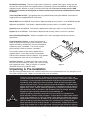
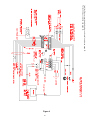
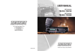
Switch A
Switch B
Switch C
Switch D
Switch E
Switch F
Horn Ring
Select
Slide Switch
GUN EMG
SGN LTD
RTD
A
WAIL
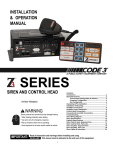
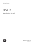
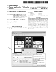
The following features are standard in the new
style 3890 series (tones and sequences may
differ by model number):
Instant-On- There is no " ON/OFF " switch. Selecting any
siren function, or keying the microphone will activate the
siren assuming the siren is connected directly to a nonignition switched source of +12V.
STANDBY
LIGHTING
RADIO
MANUAL
YELP
VOLUME
HI-LO
AIR HORN
MODEL 3894L6
YOUR POLICE DEPT.'S NAME HERE (OPTION)
Manual/Air Rotary Max. PA
Selector Volume
Horn
Adjust
Push-buttons Switch
Figure 1 - Control Panel
PA/RRB
Volume
Control
Switch
SirenLock TM (L4 and L6 Models Only)- An interlock circuit
between the siren and the light control circuits that permits
automatic siren tones only when the progressive switch is in Level 3 or in Level 2 or 3 (user selectable - works
in conjunction with the horn transfer relay). This feature is used in jurisdictions that require warning lights to be
on before the siren is activated.
Park Kill- This feature deactivates the siren tones when the vehicle is shifted into park. Once PKILL is
activated the siren will remain deactivated until an action occurs such as moving the selector switch to
STANDBY, returning lighting level switch to position one or keying the microphone. Any action will enable the
siren tones to function again with the exception of the auxillary lighting pushbuttons.On lighting models this also
drops-out the Level 3 lighting output for a power- down mode when in park.
Adjustable Backlighting- Backlighting is independent of siren power. Allows connecting to dimmer if desired.
Radio Power- Allows user to power the two-way radio from the siren when the ignition is "OFF".
Automatic Short Circuit Protection- The siren will sense a short circuit on the speaker terminals and
automatically go to standby until the fault is removed. Once the fault is removed the siren will return to normal
operation.
Lighting Level "3 " Drop-out- When vehicle is shifted to PARK and the PKILL feature is connected, Level 3
lighting will drop-out. This is indicated by the "red" LED exstinguishing. This is a power down mode and can be
defeated by setting the 4 -position rear dip switch to the PKILL "OFF" position on the lighting board.
Scroll Mode- Setting the slide switch on the rear of the siren to the SCROLL position will put siren in scroll
mode. This will allow "scrolling" through tones utilizing sharp taps on the horn ring, or a switch, via the Remote
siren input. In this mode holding the horn ring for prolonged durations will produce the Airhorn sound. See
OPERATION section for further details.
Hit-n-Go Mode - Setting the slide switch on the rear of the siren to the Hit-N-Go position will put the siren in the
Hit-n-Go mode.This mode will be most familiar to existing Mastercom users. A seven second override is
standard for all tones when activated by the Manual button or the Remote input.See OPERATION section for
details.
Automatic Siren Tones - Industry standard Wail, Yelp, and Hi-Lo tones.
AIR HORN Tone - Electronic AIR HORN sound.
Instant Public Address - Public Address override of all siren functions when the microphone Push-to-Talk key
is pressed.
Status LED - An indicator LED, visible on the front panel that informs the operator of the status of his siren at
all times.
Radio Rebroadcast - Broadcast Two-way radio reception over siren speakers. These inputs are transformer
coupled to prevent loading of the radio.
3
Remote Siren Switching - The siren accepts either a positive or a ground (earth) signal, usually from the
vehicle's horn switch (or other user supplied switch), and remotely activates the MANUAL or AIR HORN (if
supplied) function. Selection is made via the front panel slide switch.The siren is factory set for a GND
(Earth) signal and may be reconfigured to accept a positive signal. See Set-up and Adjustments section
for details.
Tone Priority/Manual Wail - The following tones are produced while pushing the MANUAL Push-button or
triggering the user-supplied REMOTE siren switch:
Manual Wail when the MANUAL Push-button is depressed while the rotary switch is in the STANDBY position.
Yelp when the MANUAL Push-button is depressed while the rotary switch is in the WAIL position.
HyperYelp when the MANUAL Push-button is depressed and the rotary switch is in the YELP position.
HyperLo when the MANUAL Push-button is depressed and the rotary switch is in the HI-LO position.
Noise Cancelling Microphone - Wired in microphone that is easily unplugged internally for service or
replacement.
Power Distribution Section - A three level progressive
switch for primary warning light system control plus 4 pushon/push-off auxiliary switches that are user convertible to
momentary action ('L4 models). The unit may also be
purchased with 6 auxiliary switches ('L6 models).
Each auxiliary switch can be custom labeled with the
supplied label kit. Each label is backlit and increases
intensity when activated to alert the operator. Each position
of the progressive switch has its own indicator LED.
Horn Ring Transfer - ('L models only) Built in horn transfer
relay that may be activated at Levels 2 and 3 of the warning
light progressive switch. Point of activation is customer
selectable with the rear panel DIP switch.
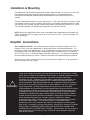
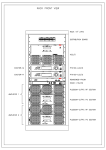
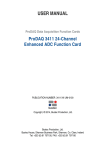
Figure 2
Unpacking & Pre-installation
After unpacking your 3890 series siren, carefully inspect the unit and associated parts for any damage that may
have been caused in transit. Report any damage to the carrier immediately
!
WARNING!
All devices should be mounted in accordance with the manufacturer’s instructions and
securely fastened to vehicle elements of sufficient strength to withstand the forces applied
to the device. Ease of operation and convenience to the operator should be the prime
consideration when mounting the siren and controls. Adjust the mounting angle to allow
maximum operator visibility. Do not mount the Control Head Module in a location that will
obstruct the drivers view. Mount the microphone clip in a convenient location to allow the
operator easy access. Devices should be mounted only in locations that conform to their
SAE identification code as described in SAE Standard J1849. For example, electronics
designed for interior mounting should not be placed underhood, etc.
Controls should be placed within convenient reach of the driver or if intended for two
person operation, the driver and/or passenger. In some vehicles, multiple control switches
and/or using methods such as "horn ring transfer" which utilizes the vehicle horn switch to
toggle between siren tones may be necessary for convenient operation from two positions.
Controls should be placed within convenient reach* of the driver or if intended for two
person operation the driver and/or passenger. In some vehicles, multiple control switches
and/or using methods such as “horn ring transfer” which utilizes the vehicle horn switch to
toggle between siren tones may be necessary for convenient operation from two positions.
4
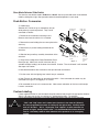
Installation & Mounting
The 3890 series siren may be mounted above the dash, below the dash, on a tunnel or in a rack with
the mounting bracket (bail) and the hardware supplied (see Fig. 2). Ease of operation and
convenience to the operator should be the prime consideration when mounting the siren and
controls.movement away from
the seat back or loss of eye contact with the
The bail is mounted to the siren chassis by means of the "T" slot in the side of the unit and the 1/4-20
carriage bolts, washers, and nuts supplied. See Figure 2 for assembly and positioning details. Note
that once the unit is installed, removal involves only loosening, not removing, the acorn nuts. Use of
1/4 - 20 HEX head bolts can damage slots and prevent easy removal of the unit.
NOTE: Set-ups and adjustments will be made in subsequent steps, depending upon the model and
options purchased, that may require access to the rear area of the unit. Plan the installation and
wiring accordingly.
Amplifier Connections
Siren Amplifier Connector - As a standard feature, the Siren and Auxiliary sections ('L4 & 'L6
models) of your unit come equipped with a combination plug-in terminal block/connector. To
terminate the wires, strip approximately 1/4" of insulation from the end of each wire and insert it in
the appropriate hole in the terminal block. Recommend using a screwdriver with a 1/8" wide blade
with a 6" shaft such as an Xcelite(C) R186 or equivalent rather than a 4 1/2" adjustment screwdriver
to ensure proper torque on the screws. Tighten the set-screw and proceed to the next connection.
Should you ever have to remove the unit, pull the terminal block straight out. It will unplug from
the unit, leaving the wiring in place.
!
WARNING!
Larger wires and tight connections will provide longer service life for components. For high
current wires it is highly recommended that terminal blocks or soldered connections be used
with shrink tubing to protect the connections. Do not use insulation displacement
connectors (e.g. 3M® ) Scotchlock type connectors). Route wiring using grommets and
sealant when passing through compartment walls. Minimize the number of splices to
reduce voltage drop. High ambient temperatures (e.g. underhood) will significantly reduce
the current carrying capacity of wires, fuses, and circuit breakers. Use "SXL" type wire in
engine compartment. All wiring should conform to the minimum wire size and other
recommendations of the manufacturer and be protected from moving parts and hot surfaces.
Looms, grommets, cable ties, and similiar installation hardware should be used to anchor
and protect all wiring. Fuses or circuit breakers should be located as close to the power
takeoff points as possible and properly sized to protect the wiring and devices. Particular
attention should be paid to the location and method of making electrical connections and
splices to protect these points from corrosion and loss of conductivity. Ground
(Earth)terminations should only be made to substantial chassis components, preferably
directly to the vehicle battery. The user should install a circuit breaker sized to
approximately 125% of the maximum Amp capacity in the supply line to protect against
short circuits. For example, a 30 Amp circuit breaker should carry a maximum of 24 Amps.
DO NOT USE 1/4" DIAMETER GLASS FUSES AS THEY ARE NOT SUITABLE FOR
CONTINUOUS DUTY IN SIZES ABOVE 15 AMPS. Circuit breakers are very sensitive to
high temperatures and will "false trip" when mounted in hot environments or operated
close to their capacity.
5
!
WARNING!
CONNECTION OF A 58 WATT SPEAKER TO THE SPKR TERMINAL WILL CAUSE THE
SPEAKER TO BURN OUT, AND WILL VOID THE SPEAKER WARRANTY!
The sound projecting opening should be pointed forward, parallel to the ground, and not
obstructed or muffled by structural components of the vehicle. Concealed or under-hood
mountings in some cases will result in a dramatic reduction in performance. To minimize
this reduction, mount the speaker so the sound emitted is projected directly forward and
obstruction by vehicle components such as hoses, brackets, grille, etc. is minimized.
Electromechanical sirens and electronic siren speakers should be mounted as far from the
occupants as possible using acoustically insulated compartments and isolation mountings to
minimize the transmission of sound into the vehicle. It may be helpful to mount the device
on the front bumper, engine cowl or fender; heavily insulate the passenger compartment; and
operate the siren only with the windows closed. Each of these approaches may cause
significant operational problems, including loss of siren performance from road slush, increased
likelihood of damage to the siren in minor collisions, and the inability to hear the sirens on ot
her emergency vehicles.
APPROPRIATE TRAINING OF VEHICLE OPERATORS IS RECOMMENDED TO ALERT
THEM TOTHESE PROBLEMS AND MINIMIZE THE EFFECT OF THESE PROBLEMS
DURING OPERATIONS.
Terminal Block Connections
10 Position Terminal Plug- ( see wiring diagram page 20 )
COM - Connect to the terminal marked "1" of one 100 W ( 11 ohm ) speaker.
SPKR - Connect to the terminal marked "2" of the 100 W ( 11 ohm ) speaker..
NOTE: An optional 200 W version is available. This will enable the user to connect two 100 W
speakers in parallel. Correct phasing is important and can be accomplished by connecting both
speaker terminals marked " 1 " to the COM terminal and both speaker terminals marked " 2" to the
SPKR terminal.
REMOTE - Remote switch (Horn ring or foot switch). Circuit can be configured for both ground
(earth) or positive signals. A horn ring transfer circuit is standard in all 3940 series "L" models.
Connect to the "REMOTE" terminal on the Lighting Control Section terminal block. Unit is
configured for a ground ( earth ) at the factory. See page 7 for details on configuring for a +12V
input.
BLTG- Provides +12V to siren backlighting. Connect to a vehicle circuit that is powered when the
ignition switch is " on ". If backlighting dimming is desired, connect to the dash lights' circuit.
Caution- If connected to the battery the backlighting will be active at all times.
PKILL- This feature automatically deactivates siren tones when the vehicle is shifted into PARK.
On models with lighting control Level 3 will " drop-out " if this feature is enabled via the rear panel
dip switch. Siren tones will be disabled until the vehicle is shifted out of PARK and the front panel
selector switched is either returned to standby ( or another function is selected ) or the lighting
level control is returned to level 1.
This circuit is activated by a negative signal. Connect this input to a circuit that is GROUNDED
(Earth) when the vehicle is shifted into PARK. It is the installer's responsibility to determine an
appropriate location in the vehicle circuitry to connect this wire.
RRB - Connect to one side of the two-way radio speaker.
RRB - Connect to the second side of the two-way radio speaker.
EXPWR - Connect directly to +12V terminal of the battery or a non-ignition switched source of +12V
capable of supplying a minimum of 10 Amps.
6
RPWR- Provides +12V to the two-way radio with the ignition on / off . Connect the +12V power lead
from the radio to this terminal. This is a 10 Amp maximum current output.
InterClear® (Optional) - Connect to the device or circuit that is to be activated by the InterClear
feature.The InterClear circuit is internally current limited at 1 Amp. Should your requirements require
higher currents, use the InterClear Power Booster Kit (# INTBS), available from your Code 3 supplier.
1/4" Male Quick-Connect Printed Circuit Board Terminals
+12V - Connect to a positive +12 volt DC source. It is recommended that the user protect this wire
with a 10 Amp fuse(20 Amp for 200w option) or circuit breaker located at the source. Use #14 gauge
wire terminated with 1/4" female, fully insulated quick-connect terminals only.
NEG - Connect to the negative terminal of the battery. This supplies ground (earth) to the siren.
Use #14 gauge wire terminated with 1/4" female, fully insulated quick-connect terminals only.
Power Distribution Connections ( "L" Models)
A #8 stud is provided on the rear of the unit and is intended for use ONLY as a convenient ground
(earth) " tie-point " for the light bar wiring. It is not an adequate ground (earth) for the siren or
the light bar. It is recommended all ground (earth) wires attached here be terminated with a
crimp-on ring terminal.
11-Position Terminal Plug - Rear Panel- (See Wiring Diagram page 20)
IMPORTANT!
Remember auxillary outputs A,B,D on L4 models and A,B,D,E,F on L6 models can supply a
maximum of 20 Amps each for a combined total of 30 Amps. Install appropriate fuses in each
output wire as close to the siren as possible.
SW D - Connect to the load to be controlled by Auxiliary Switch "D".
SW B - Connect to the load to be controlled by Auxiliary Switch "B".
SW C NO - Connect to the load to be controlled by the normally-open contact on Auxiliary Switch
"C".
SW C NC - Connect to the load to be controlled by the normally-closed contact on Auxiliary Switch
"C".
SW C COM - Common or power feed for Auxiliary Switch "C". Terminals are a SPDT circuit that may
be connected as a momentary (or timed momentary with option) ignition controlled circuit, or used for
switching auxiliary circuits. It will Handle 10 Amps, and should be protected with a fuse at the battery
if individually fed. Can also be connected to a ground source if the load on SWC NO or SWC NC is
already connected to a 12V source and needs a ground input to activate it.
SW F - ('L6 models only) Connect to the load to be controlled by Auxiliary Switch "F".
SW A - Connect to the load to be controlled by Auxiliary Switch "A".
SW E - ('L6 models only) Connect to the load to be controlled by Auxiliary Switch "E".
HORN RING - Connect to the wire coming from the vehicle horn switch at the steering wheel.
HORN - Connect to the vehicle horn or vehicle horn ring relay.
7
REMOTE - Connect to the Remote terminal on the Siren Amplifier Connector.
Lighting Models Only ( L versions )
#8 GAUGE RED WIRE PIGTAIL - provides power to the 3 Level, progressive lighting outputs only.
The wire can be ordered with an optional connector to allow for convenient removal. The connector
should be soldered to each wire, NOT crimped. This connection is designed to provide 50 amp
service and therefore nothing smaller than #8 guage wire should be connected to it.The circuit breaker
used should be sized for the actual load of the lighting used and located as close to the battery
positive as possible. For quick disconnection option on 8 AWG wire see "lighting switch connector"
on page 23.
4 Position Screw-type Terminal Block Connector
Important!
The total combined current for the auxillary outputs A,B,D on L4 models and A,B,D,E,F on L6
models must not exceed 30 Amps total.
+12VAUX - Connect to the positive terminal of the battery with 30 Amp circuit protection. Locate the
fuse or circuit breaker at the battery and use #10 gauge wire minimum. This terminal powers
switches A,B and D on L4 models and A,B,D,E and F on L6 models, and also supplied power to the
siren lock & light alert circuits on both models.
LEVEL 1 - Connect to the first level of warning lights (Green LED) position "1" on level switch.
LEVEL 2 - Connect to the second level of warning lights (Yellow LED) position "2" on level switch.
LEVEL 3 - Connect to the third level of warning lights (Red LED) position "3" on level switch.
NOTE: LEVEL 1, LEVEL 2, LEVEL 3, switch progressively. Switch position 1 provides +12 volts at
Level 1 terminal. Switch position 2 provides +12 volts at terminals 1 and 2. Switch position 3
provides +12 volts at terminals 1, 2, and 3.
SET-UP AND ADJUSTMENT
All of the adjustments, except MAXIMUM P.A. ADJUSTMENT, and set-up switches are
accessible from the rear of the unit. Make these adjustments and position the set-up switches prior
to placing the unit inside their bail bracket (see wiring diagram, page 20).
Audio Adjustments
Radio Rebroadcast Adjustment - Place the selector switch in the RADIO position. The trimmer
located on the rear panel of the siren sets the maximum level RRB will reach with the knob fully
clockwise. To adjust properly, set the volume knob fully clockwise and adjust the trimmer such that
normal two-way radio volume inside the vehicle produces the desired volume outside the vehicle.
Maximum P.A. Volume Adjustment - This trimmer ( located on the front panel next to the volume
control knob ) sets the maximum level that the P.A. volume will reach with the front panel VOLUME
control in the fully clockwise position.To adjust properly, set the front panel volume control fully
clockwise and adjust the trimmer while keying the microphone until the maximum volume out of the
speaker is such that there is no feedback and is intelligible. (See Figure 1)
8
Remote Input
The remote input can be configured to accept either a positive +12V or negative GND ( Earth ) signal
for actuation. All new style 3890 series sirens are shipped set-up to accept the GND (Earth) signal
from the vehicle HORN SW present on most vehicles. To reconfigure this as a +12V signal the rear
plate must be removed ( see assembly explosion page 19 ). Place both jumpers towards the "+ "
position. Refer to Detail "A" shown above for a complete illustration.
4-Position DIP Switch
Gently set the SirenLock, PKILL and LightAlert set-up switches to the desired position with a pencil
point or some other pointed object. These switches are present even if LightAlert were not specified.
If switched on, all of the tones except AIR HORN, mute until the Warning Light Switch is in either the
Level 3 or the Level 2 or 3 positions.
SirenLock - In position "3" the siren tones are allowed to sound and the horn ring relay transfers
when the Warning Light switch is placed in the Level "3" position. In position "2,3" the siren tones
are allowed to sound and the horn ring relay transfers when the Warning Light switch is placed in
either Level 2 or in Level 3 position.
LightAlert - When in the ON position, enables the LightAlert tone, which alerts the operator
audibly when any lighting switch is activated. When in the OFF position, defeats the LightAlert
tone.
PKILL- When vehicle is shifted to PARK lighting level 3 will " drop-out " if this switch is in the "on
"position. This is intended to reduce power consumption while vehicle is not moving. If it is not
desired to have level 3 "drop-out" this switch should be set to the " OFF " position on the dip
switch. This will not defeat the PKILL feature on the siren, but will defeat the level 3 DROP
out.
9
Siren Mode Selector Slide Switch
The siren has two distinct modes, Hit-N-Go and Scroll. Set rear panel slide switch to the desired
mode by sliding left or right. See operation section for detailed opertion in each mode.
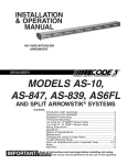
Push-Button Conversion
('L models only)
Switches A-F can be set up as momentary (only on
while pushed), or push-on/push-off. They can be
converted as follows:
Switch with
pin intact
Grasp pin
at this end
1. Disconnect all connectors and wiring to unit.
Remove siren from the vehicle if it is installed.
2. Remove the screw holding the rear cover plate to the
siren tray.
3. Remove the (4) screws holding the bezel to the
extrusion.
4. Slide the front panel/tray assembly forward out of the
extrusion.
Rotate pin
toward front of
switch
Lift pin
out and
store for
further
use
5. Grasp the rear edge of the Power Distribution Circuit
Figure 3
Board (on top), slide it back and lift it free from the (4)
standoff fasteners holding it to the lower circuit board. Caution: The circuit board is still attached.
See steps 6 & 7 below.
6. Note the orientation of the circuit board four-pin connector and remove.
7. Do the same with the lighting level switch four-pin connector.
8. See Figure 3 for information on converting the switch. Once converted the switch may be
converted back again if the toggle pin is not lost.
9. Re-assemble the siren in the reverse order. Note correct orientation of the four and three-pin
harness connectors.
Custom Labeling
Labels supplied with the L4 and L6 models should be selected and placed in the appropriate windows.
See fig 1 for front view of siren, for switches A-F window designations. The windows
can be accessed by removing the (4) screws holding the bezel to the siren chassis extrusion.
!
WARNING!
"Wail" and "Yelp" tones are in some cases (such as in the state of California)
the only recognized siren tones for calling for the right of way. Ancillary tones
such as "Air Horn", "Hi-Lo", "Hyperyelp", and "Hyperlo" in some cases do not
provide as high a sound pressure level. It is recommended that these tones be
used in a secondary mode to alert motorists to the presence of an emergency
vehicle.
10
P.A. VOLUME Knob - This control adjusts the level of the P.A. audio produced when keying the microphone
and speaking into it. This control also controls the Radio Re-broadcast level when in the " Radio " position (see
SET-UP, Radio Rebroadcast Adjustment on p. 8).
Operation
IMPORTANT !
The Mastercom Series has two distinct modes of operation. These are the Hit-N-Go mode and the
SCROLL mode. The desired mode of operation can be selected via the rear panel slide switch. Each
mode will effect the siren operation as described below. The Hit-N-Go mode should be most familiar
to existing Mastercom users.
The siren tones will be deactivated when the vehicle is in "PARK" if the PKILL feature has been
connected. To test the siren tones the vehicle must not be in "PARK". The following assumes that
PKILL has not been activated.
Switch Operation - Hit-N-Go Mode Selected
Function Selector Switch (Center Knob)
RADIO - In the RADIO position, the audio from the 2-way radio is rebroadcast over the siren speaker. The
siren tones (Wail, Yelp, & Hi-Lo) do not operate in this position. In addition, power is routed to the two-way
radio via the RPWR pin on the rear panel connector. The EXPWR pin must be wired to the battery positive ,
and the two-way radio power connected to the RPWR pin.
STANDBY - This is the standby mode. If the MANUAL button is depressed , and the vehicle is not in
PARK, the Manual wail tone will ramp up until it reaches a peak then ramp down when released. If the AIR
HORN button is depressed, the Air Horn sound will be produced.
WAIL - This position produces the Wail tone. Depressing the MANUAL button or activating the remote input
will now produce the Yelp tone for 7 seconds. Depressing the AIR HORN button will produce the Air Horn
sound and when released will return siren to Wail tone.
YELP - This position produces the Yelp tone. Pushing the MANUAL button or activating the remote input will
now produce the HyperYelp tone for 7 seconds. If the AIRHORN button is pushed, the Airhorn sound will be
produced and when released will return the siren to Yelp.
HI-LO - This position produces the Hi-Lo tone. Pushing the MANUAL button or activating the remote input
will now produce the HyperLo tone for 7 seconds. If the AIRHORN button is pushed, the Airhorn sound will
be produced and when released will return siren to Hi-Lo.
Push-to-Talk (PTT) Microphone Switch - Keying the microphone will automatically override whatever
mode the siren is in and broadcast public address messages over the siren speaker. PTT operates in all
positions of the Selector switch.
MANUAL Pushbutton Momentary Switch -Has no effect when the selector switch is in RADIO, produces
the effects described above for each selector position.
AIR HORN Pushbutton Momentary Switch- Produces the Air Horn tone in all selector switch settings
except RADIO.
SLIDE SWITCH - The slide switch located between the AIR HORN and MANUAL buttons selects the
function for the REMOTE (external switch) circuitry. When the switch is to the right, the Horn Ring
circuitry remotely "depresses" the AIR HORN button and it produces the effects outlined above. When the
slide switch is to the left, it allows the REMOTE circuitry to remotely "depress" the MANUAL pushbutton.
This causes the effects described above to occur.
11
Switch Operation - Scroll Mode Selected
The " Scroll " mode is designed to allow the user to scroll through all the tones including Airhorn by utilizing
the Remote input on the siren. This will usually be connected to the vehicle Horn Ring circuit. When the
siren selector switch is placed in either Wail or Yelp ( and Horn Ring transfer has occured ) the user can
use the Horn Ring to sequence through Wail,Hyperyelp and Yelp by applying a quick, sharp tap on the horn.
Additional taps will scroll the siren to the next tone. Depressing the horn ring for longer periods will produce
" Airhorn". After releasing the vehicle's horn ring, the siren will return to the selected tone.
Function Selector Switch (Center Knob)
RADIO - In the RADIO position, the audio from the 2-way radio is rebroadcast over the siren speaker. The
siren tones (Wail, Yelp, & Hi-Lo) do not operate in this position. In addition, power is routed to the two-way
radio via the RPWR pin on the rear panel connector. The EXPWR pin must be wired to the battery positive ,
and the two-way radio power connected to the RPWR pin.
STANDBY - This is the standby mode. If the MANUAL button is depressed the Manual wail tone will ramp
up until it reaches a peak then ramp down when released. If the AIR HORN button is depressed, the Air
Horn sound will be produced. The siren cannot be scrolled in this position.
WAIL - This position produces the Wail tone. Depressing the MANUAL button will now produce Manual wail
tone and ramp up until released. Depressing the AIR HORN button will produce the Air Horn sound.The siren
can be scrolled in this position as described above.
YELP - This position produces the Yelp tone. Pushing the MANUAL button will now produce the Manual wail
tone and ramp up until released. If the AIRHORN button is pushed, the Airhorn sound will be produced.The
siren can be scrolled from this position as decribed above.
HI-LO - This position produces the Hi-Lo tone.Pushing the MANUAL button will now produce the HyperLo
tone for 7 seconds. If the AIRHORN button is pushed, the Airhorn sound will be produced and when
released will return siren to Hi-Lo.The siren cannot be scrolled from this position.
Push-to-Talk (PTT) Microphone Switch - Keying the microphone will automatically override whatever
mode the siren is in and broadcast public address messages over the siren speaker. PTT operates in all
positions of the Selector switch.
MANUAL Pushbutton Momentary Switch -Has no effect when the selector switch is in RADIO, produces
the effects described above for each selector position.
AIR HORN Pushbutton Momentary Switch - Produces the Air Horn tone in all selector switch settings
except RADIO.
SLIDE SWITCH - The slide switch located between the AIR HORN and MANUAL buttons selects the
function for the REMOTE (external switch) circuitry. When in the "Scroll " mode this switch has no
effect unless in STANDBY or the Hi-Lo position. When this is the case the switch functions as
follows:
When the switch is to the right, the Horn Ring circuitry remotely "depresses" the AIR HORN button and it
produces the effects outlined above. When the slide switch is to the left, it allows the REMOTE circuitry to
remotely "depress" the MANUAL pushbutton. This causes the effects described above to occur.
LED STATUS INDICATOR - The green LED status indicator indicates the siren is on when lighted. The LED
will remain off unless a siren tone or air horn or PA or radio output is selected.
12
-For 'L4 & 'L6 Models OnlyWARNING LIGHTS 3 LEVEL PROGRESSIVE SLIDE SWITCH:
POSITION 1 - Supplies power to Lighting Level 1, illuminates Green LED and activates LightAlert if supplied.
POSITON 2 - Supplies power to Lighting Levels 1 & 2. illuminates Green & Yellow LED's and activates
LightAlert and SirenLock options if supplied.
POSITION 3- Supplies power to Lighting Levels 1,2, & 3. Illuminates Green, Yellow, and Red LED's; and
activates LightAlert and SirenLock if supplied.
Auxiliary Switches:
AUXILIARY SWITCH "A" - Supplies power to the load connected to terminal SW A.
AUXILIARY SWITCH "B" - Supplies power to the load connected to terminal SW B.
AUXILIARY SWITCH "C" - Operates circuit connected to terminals SWC NO, SWC NC, SWC COM.
Optional functions a momentary activation or a 5 sec. timed switch.
AUXILIARY SWITCH "D" - Supplies power to the load connected to terminal SW D.
-For 'L6 Models OnlyAUXILIARY SWITCH "E" - Supplies power to the load connected to terminal SW E.
AUXILIARY SWITCH "F" - Supplies power to the load connected to terminal SW F.
NOTE: All switches have their own individual LED indicating that the circuit is On. All switches will activate
the LightAlert feature if it is supplied.
LightAlert - The LightAlert option will produce an audible "beep" on a periodic basis if the Warning Light
Switch or any of the Auxiliary Switches are on. A rear accessible circuit board mounted DIP switch is
provided to defeat this option.
SirenLock - The SirenLock, when not defeated by means of a rear panel accessible switch, allows siren tones
(Wail, Yelp, and Hi-Lo) to be produced only when the Warning Light Switch is in the Lighting Level 2 (Green and
Yellow LED's) or Lighting Level 3 (Green, Yellow, and Red LED's) position (switch selectable via a rear panel
accessible switch). Air Horn, Radio Rebroadcast, and Public Address are unaffected by this option.
MAINTENANCE
Your Code 3® 3890 series siren has been designed to provide trouble free service. In case of difficulty, see
Troubleshooting (page 14,15 ). Also check for shorted or open wires. The primary cause of short circuits
has been found to be wires passing through firewalls, roofs, etc. If further difficulty persists, contact the
factory for troubleshooting advice or return instructions. Public Safety Equipment, Inc. maintains a complete
parts inventory and service facility at the factory and will repair or replace (at the factory's option) any unit
found to be defective under normal use and in warranty. Any attempt to service a unit in warranty by anyone
else other than a factory authorized technician without express written consent by the factory, will void the
warranty.
Units out of warranty can be repaired at the factory for a nominal charge on either a flat rate or parts and
labor basis. Contact the factory for details and return instructions. Public Safety Equipment, Inc. is not
liable for any incidental charges related to the repair or replacement of a unit unless otherwise expressly
agreed to in writing by the factory.
13
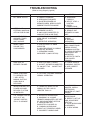
TROUBLESHOOTING
(Refer to wiring diagram page 20)
PROBLEM
PROBABLE CAUSE
NO SIREN OUTPUT.
A. PARKKILL ENGAGED
B. SIRENLOCK EXGUAGED
C. SHORTED SPEAKER OR
SPEAKER WIRES. SIREN IN OVER
CURRENT PROTECTION MODE.
INTERNAL OR
EXTERNAL 10AOR 20A
OPTION FUSE BLOWS.
A. AMPLIFIER POWER WIRES
REVERSED POLARITY
B. 200W LOAD CONNECTED TO
100W UNIT FOR 10 AMP FUSE
A. SPEAKER NOT CONNECTED/
OPEN CIRCUIT IN SPEAKER
WIRING
B. DEFECTIVE SPEAKER(S)
NO OUTPUT FROM
SPEAKER, TONES
HEARD INSIDE
AMP. MODULE.
SIREN TONES
VOLUME TOO
LOW/GARBLED.
A. LOW VOLTAGE TO SIREN
AMPLIFIER
B. HIGH RESISTANCE IN WIRING/
DEFECTIVE SPEAKER
C. SPEAKERS PHASED
IMPROPERLY (200W OPTION)
HIGH RATE OF
SPEAKER FAILURE.
A. HIGH VOLTAGE TO SIREN
B. 58 WATT SPEAKER CONNECTED
TO 100 WATT TAP. 58 WATT NOT
ALLOWED.
SIREN CONTINUES
TO OPERATE FOR
7 SEC. AFTER
MANUAL BUTTON/
HORN RING IS
RELEASED.
A. "HIT-N-GO" FEATURE ENGAGED.
NORMAL OPERATION
INTERCLEAR WILL NOT
POWER AUXILIARY
DEVICES. IF OPTION
IS INSTALLED.
A. THERE IS A SHORT IN THE
WIRING, OR THE LOAD IS
GREATER THAN 1 A.
P.A. VOLUME LOW OR
NO P.A. AT ALL.
VOLUME CONTROL
FULLY CLOCKWISE.
A. DEFECTIVE MICROPHONE
B. MAXIMUM P.A. VOLUME
TRIMMER MISADJUSTED. SEE SETUP AND ADJUSTMENT SECTION.
C. MICROPHONE NOT
COMPLETELY PLUGGED IN.
D. COMMON MICROPHONE
CIRCUIT NOT PROPERLY WIRED.
E. INCORRECT MICROPHONE.
14
REMEDY
A. DISENGAGE
PARKKILL
B. SELECT LEVEL 3
LIGHTING
C. CHECK
CONNECTIONS
A. CHECK POLARITY
B. REMOVE ONE
SPEAKER ON 100W
UNIT.
A. CHECK SPEAKER
WIRING
B. REPLACE
SPEAKER(S)
A. CHECK WIRING FOR
BAD CONNECTIONS/
CHECK VEHICLE
CHARGING SYSTEM
B. CHECK SPEAKER(S)
WIRING/REPLACE
SPEAKER(S)
C. REFER TO PAGE 6
FOR PROPER
PHASING
A. CHECK VEHICLE
CHARGING SYSTEM
B. USE CORRECT
SPEAKER
A. CHECK FOR
SHORTS. INSTALL
INTERCLEAR
BOOSTER KIT (PART
#INTBS)
A. REPLACE
MICROPHONE
B. REFER TO SET-UP
AND ADJUSTMENT
SECTION
C. PLUG MICROPHONE
IN SECURELY
D. CHECK WIRING
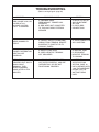
TROUBLESHOOTING
(Refer to wiring diagram page 20)
PROBLEM
PROBABLE CAUSE
REMEDY
RRB VOLUME LOW, OR
NO RRB AT ALL.
VOLUME CONTROL
FULLY CLOCKWISE.
A. MAXIMUM RADIO
REBROADCAST TRIMMER MISADJUSTED
B. RRB WIRES NOT CONNECTED
TO TWO-WAY RADIO EXTERNAL
SPEAKER
A. REFER TO SET-UP
AND ADJUSTMENT
SECTION
B. CHECK RRB
CONNECTIONS
SIREN SOUNDS BY
ITSELF
A. REMOTE SWITCH (HORN RING)
WIRING FROM TERMINAL REMOTE
SHORTING TO POSITIVE OR TO
GROUND (EARTH).
A. CHECK WIRING FOR
ANY SHORTING.
A. SUPPLY FUSE OPEN
B. SIREN NEGATIVE TERMINAL
NOT GROUNDED
A. REPLACE FUSE.
B. RECONNECT
NEGATIVE TERMINAL
TO GROUND.
A. VEHICLE CIRCUIT BREAKERS
NOT RATED PROPERLY, AND ARE
OVERHEATING, OR ARE NOT
FUNCTIONING PROPERLY
A. REFER TO
SPECIFICATIONS
SECTION, PAGE 18.
USE A BREAKER WITH
1.25x THE AMPERAGE
RATING FOR THE
WATTAGE BEING
USED.
POWER DISTRIBUTION
SECTION NOT
WORKING
SIREN RUNS
PROPERLY BUT SHUTS
DOWN WHILE
RUNNING, THEN
STARTS RUNNING
AGAIN AFTER A FEW
MINUTES
15
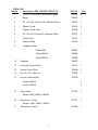
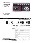
Parts List
Ref No.
Description (SEE FIGURE 4 PAGE 19)
Part No.
Qty.
1
#6 x 1/2, Pan Hd Phil, Sheet Metal Screw
T02797
8
2
Bezel
T03542
1
3
#4 - 40 x 3/8", Pan Hd. Phil., Machine Screw
T06937
2
4
Selector Knob
T03537
1
5
Selector Knob Insert
T03538
1
6
#4 - 40 x 3/8, Flat Hd Phil., Machine Screw
T01011
2
7
Switch Knob
T01917
1
8
Molded Guide
T01916
1
9
Faceplate Label -
1
Model 3892
T06997
Model 3892L4
T06996
Model 3892L6
T06995
10
Faceplate
T08657
1
11
Horizontal Rotary Switch
T01116
1
12
Volume Control Knob
T03536
1
13
3/8 - 32 x 1/2 x .090" Nut
T01082
2
14
Custom Label Window
T03539
15
Models 3892L4
2
Models 3892L6
3
Strain Relief
T07310
1
T07311
1
T07309
1
Models 3892, 3892L4, 3892L6
16
Microphone Wired
Models, 3892, 3892L4, 3892L6
17
Microphone, Plug-in
16
18
Fish Paper Gasket
T01363
4
19
Spacer
T08659
1
20
Transistor Insulating Pad
T06363
2
21
#4 - 40 Nylon Insert Stop Nut
T03594
2
22
Microphone Jack (Option)
T06147
1
23
Siren Amp. Circuit Board
T50002
1
Models 3892, 3892L4, 3892L6
24
Circuit Board Standoff
T05172
4
25
#6 - 32 Rd Hd Phil., Machine Screw
T01030
4
T10805
1
26
27
Lamp, Miniature, 14VDC
Lighting Pushbutton Actuator
T03540
Models 3892L4
28
6
Models 3892L6
8
Model 3892
2
Lighting Circuit Board
T50005
1
T50004
1
Models 3892L4
29
Lighting Circuit Board
Models 3892L6
30
E - Tray Pemserted
T03100
1
31
Tinnerman Clip
T01058
1
32
Label Set
T10859
1
33
Chassis
S55133
1
34
Mounting Bail
T08660
1
35
Acorn Nut
T00183
4
36
#8 - 32 x 5/8, Hex Hd, Machine Screw
T00763
1
37
Backplate
1
17
Model 3892
S71332
Model 3892L4
S71328
Model 3892L6
T08658
38
Airbag Warning Label
T09937
1
39
1/4 Internal Tooth Star Lock Washer
T06935
4
40
#12 Flat Washer
T01295
4
41
C - Bolt, 1/4 - 20
T06138
4
42
Internal Harness
T10920
1
43
#6 x 3/8 Hex Hd, Sheet Metal Screw
T01031
1
44
Fuse, Blade Type Term., 10A
T06313
1
Fuse, Blade Type Term., 20A
T01031
1
#8 - 32 Kep Nut
T00674
2
45
18
24
25
26
27
29 28
39
30
43
40
24
Figure 4
19
31
32
41
24
42
34
35
33
37
36
44
33
38
46
45
Installer: Please record model number and serial number on page 25.
For technical assistance see page 25.
Figure 4
20
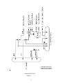
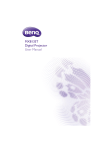
for
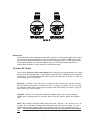
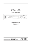
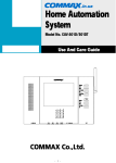
External Ignition Lead Relay
3890 Series Siren Systems
DESCRIPTION:
Normal installation procedure requires the siren’s +12VDC power connection to be connected to the vehicle’s
ignition circuit so that the ignition key must be in the on position for the system to operate. In cases where
vehicle security is a consideration it may be desirable to connect the siren system directly to the vehicle’s
battery in order to allow the siren and lighting control to be operated with the vehicle’s ignition switch in the off
position. This requires that the siren’s +12VDC power connection be routed through the normally closed (NC)
contacts of a SPDT relay (user supplied). This is easily accomplished using the wiring method described below.
OPERATION:
Refer to the appropriate user instruction manual for details on the configuration and operation of the
MasterCOM Siren System.
WIRING:
The basic connections are shown in Fig. 1 below. Please note that other equivalent relays and vehicles of
different makes and models may require slightly different connections. Mount and wire the siren amplifier in
compliance with the instructions in the user manual. Read and comply with all safety warnings. Refer to the
vehicle manufacturer’s wiring diagram to determine the location and wire color of the start circuit. Securely
mount the external relay. Use the appropriate wire size as indicated in Fig. 1, and insure that all wiring is
properly terminated and secured in a manner that does not interfere with other systems within the vehicle.
+12VDC FROM BATTERY
PSE P/N 680
BOSCH 0 332-204-150
OR EQUIVALENT
20A FUSE
(USER SUPPLIED)
NC (87a)
TO SIREN +12VDC
QUICKSLIDE CONNECTOR
C (30)
N0 (87)
WIRE SIZE - 12 AWG
WIRE SIZE - 12 AWG
(85)
TO VEHICLE START CIRCUIT
R/LB WIRE
ON FORD CROWN VIC
WIRE SIZE - 18 AWG
(86)
GROUND
External relay wiring to allow electronic siren
and lighting control to operate directly from
vehicle battery (vehicle ignition OFF) and
provide ignition reset to siren during vehicle restart.
Fig. 6
21
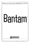
CUSTOMER SUPPLIED
DOUBLE POLE DOUBLE
THROW (DP/DT) RELAY
COMMON MIC OPTION
FIGURE 7
22
Options
Lighting Switch Connector- Connectors which when soldered to the #8 wire and the user supplied power wire
offers quick disconnect service.
200W Speaker Output - An optional 200 watt version is available. This enables the user to connect two 100w
speakers in parellel.
No HI-Low Siren Tones - "wail" and "yelp" tones are in some cases (such as in the state of California) the only
recognized siren tones for calling for the right of way.
Instant Yelp - This porduct is provided with an INSTANT YELP feature which allows the user to select the
YELP tone instantly by depressing the vehicles's horn switch.
Remote MIC Jack - A plug-in microphone jack in lieu of the standard wired-in microphone may be specified. A
plug-in noise-anceling microphone (p/n T07309) must be ordered seperately if needed.
LightAlert TM (L4 and L6 Models Only)- An audible alarm pulse that indicates that either the primary warning
system or one of the auxiliary control circuits is on. User defeatable.
InterClear® This unique feature can be used to activate additional warning lights for 7 seconds when in an
Hit-N-Go override or " scrolling " by pushing a single button or the vehicle horn ring, thus allowing an additional
level of warning in situations such as intersections without the operator having to take his hands off the wheel
or his eyes off the road.
InterClear Booster Kit (part#intbs) Increases interclear option's output capability for loads greater than 1 amp.
Custom Engraving (CUSENG) - The lower portion of the faceplate can be engraved with department name or
other information.
Air Horn only - This option disables the primary and secondary siren tones while still enabling the Air horn
tone, Radio Rebroadcast and PA outputs. The promary warning and auxiliary lighting controls remain
uneffected.
Specifications
Siren Section
Input Voltage 10 to 16 VDC, negative ground (earth).
(Note: Operation above 15 VDC for an extended period of time may result in speaker damage.)
Operating Current:
8 Amps @ 13.6V with 11-ohm load ( 100 W Spkr )
For optional 200 Watt operation: 14 Amps @ 13.6V with 5.5-ohm load ( 2- 100 W Spkr )
Note: There is no 58 Watt speaker connection available.
Standby Current:
12 mA excluding backlighting
Cycle Rate:
WAIL - 11 cycles/minute.
YELP - 200 cycles/minute.
64 V peak-to-peak
Voltage Output ( approx. )
Audio Section
Audio Response:
Audio Distortion:
3 dB down points - 500 to 3000 hz.
1000 hz. 0 dB Reference
10% or less below clipping.
23
Lighting Section ("L" Models Only)
Warning Light Control: Progressive switching, 3 levels
50 Amps. maximum combined total to #8 wire
Audible alarm (optional).
Level 1
30A maximum
Green LED Indication
Level 2
30A maximum
Yellow LED Indication
Level 3
30A maximum
Red LED indication.
Auxiliary Control - SPST ( Aux. Switches A, B,C,D,E, F )
Accessory Switch operation - Push-on/off convertible to momentary operation.
Independent circuits - 4 ('L4), 6 ('L6).
30 Amps. maximum combined total
20 Amps. maximum load for any single output A,B,C,D,E or F
Green LED indication.
Audible alarm (optional).
Horn Transfer Relay - SPDT:
Activated in Level 2 or Levels 2 & 3 (User selectable).
10 Amps. maximum connected load.
24
For Technical assistance phone (314) 426-2700 and then press option 2 when you hear the recording.
For Technical Service direct FAX (314) 429-2962.
or www.code3pse.com
Please have model number and the serial number of the unit handy before calling.
Model number 394_L_
Serial Number
NOTES:
25
WARRANTY
Code 3, Inc.'s emergency devices are tested and found to be operational at the time of
manufacture. Provided they are installed and operated in accordance with manufacturer's
recommendations, Code 3, Inc. guarantees all parts and components except the lamps to a period
of 1 year (unless otherwise expressed) from the date of purchase or delivery, whichever is later.
Units demonstrated to be defective within the warranty period will be repaired or replaced at the
factory service center at no cost.
Use of lamp or other electrical load of a wattage higher than installed or recommended by
the factory, or use of inappropriate or inadequate wiring or circuit protection causes this warranty
to become void. Failure or destruction of the product resulting from abuse or unusual use and/
or accidents is not covered by this warranty. Code 3, Inc. shall in no way be liable for other
damages including consequential, indirect or special damages whether loss is due to negligence
or breach of warranty.
CODE 3, INC. MAKES NO OTHER EXPRESS OR IMPLIED WARRANTY INCLUDING,
WITHOUT LIMITATION, WARRANTIES OF FITNESS OR MERCHANTABILITY, WITH
RESPECT TO THIS PRODUCT.
PRODUCT RETURNS
If a product must be returned for repair or replacement*, please contact our factory to
obtain a Return Goods Authorization Number (RGA number) before you ship the product to
Code 3, Inc. Write the RGA number clearly on the package near the mailing label. Be sure
you use sufficient packing materials to avoid damage to the product being returned while in
transit.
*Code 3, Inc. reserves the right to repair or replace at its discretion. Code 3, Inc. assumes no responsibility or liability for expenses
incurred for the removal and /or reinstallation of products requiring service and/or repair.; nor for the packaging, handling, and shipping: nor for the
handling of products return to sender after the service has been rendered.
PROBLEMS OR QUESTIONS? CALL OUR TECHNICAL ASSISTANCE HOTLINE (314) 996-2800
Public Safety Equipment, Inc.
10986 N. Warson Road
St. Louis, Missouri 63114-2029—USA
Ph. (314) 426-2700 Fax (314) 426-1337
www.code3pse.com
Code 3 is a registered trademark of Code 3, Inc. a subsidiary of Public Safety Equipment, Inc.
Revision 3, 11/05 - Instruction Book Part No. T06998
©2005 Public Safety Equipment, Inc. Printed in USA