1
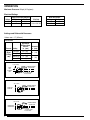
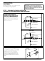
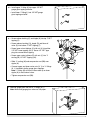
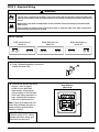
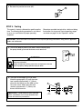
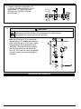
McDonnell & Miller
Series 42S
Installation & Maintenance
Instructions
MM-231(D)
®
(Snap Switch)
Low Water Cut-Off/Pump Controller
For Steam Boilers
Series 42S
Typical Applications:
– Pump controller/low water fuel cut-off
for steam boilers
– Low water cut-off
Series 42S-A
Series 42S-N
! WARNING
CAUT
WARN
ING
ION
• Before using this product read and understand instructions.
• Save these instructions for future reference
• All work must be performed by qualified personnel trained in the proper application, installation, and maintenance of plumbing, steam, and electrical equipment and/or systems in
accordance with all applicable codes and ordinances.
• To prevent serious burns, the boiler must be cooled to 80˚F (27˚C) and the pressure must be
0 psi (0 bar) before servicing.
• To prevent electrical shock, turn off the electrical power before making electrical connections.
• This low water cut-off must be installed in series with all other limit and operating controls
installed on the boiler. After installation, check for proper operation of all of the limit and
operating controls, before leaving the site.
• We recommend that secondary (redundant) low water cut-off controls be installed on all
steam boilers with heat input greater than 400,000 BTU/hour or operating above 15 psi of
steam pressure. At least two controls should be connected in series with the burner control
circuit to provide safety redundancy protection should the boiler experience a low-water
condition. Moreover, at each annual outage, the low water cut-offs should be dismantled,
inspected, cleaned, and checked for proper calibration and performance.
• To prevent serious personal injury from steam blow down, connect a drain pipe to the control
opening to avoid exposure to steam discharge.
• To prevent a fire, do not use this low water cut-off to switch currents over 7.4A, 1/3 Hp at
120 VAC or 3.7A, 1/3 Hp at 240 VAC, unless a starter or relay is used in conjunction with it.
Failure to follow this warning could cause property damage, personal injury or death.
OPERATION
Maximum Pressure: 50 psi (3.5 kg/cm2)
Electrical Ratings
Voltage
120 VAC
240 VAC
Pump Circuit Rating (Amperes)
Full Load
Locked Rotor
7.4
44.4
3.7
22.2
Pilot Duty
345 VA at
120 or 240 VAC
Settings and Differential Pressures
Values are ± 8” (3.2mm).
Series 42S
Approximate
Distance Above
Cast Line
Differential
In. (mm)
In. (mm)
Setting
Pressure
50 psi
(3.5 kg/
cm2)
Pump Off
Pump On
13/8 (35)
5/8
(16)
Burner On
Burner Off
7/8
0
(22)
(0)
3/4
(19)
7/8
(22)
1 3/8" (35mm)
NORMAL BOILER
WATER LINE
PUMP
OFF
BURNER
OFF
CUT-OFF
LEVEL
BURNER
CUT-OFF LEVEL
AT CAST LINE
3/4" (19mm)
NORMAL BOILER
WATER LINE
PUMP OFF
PUMP ON
CUT-OFF
LEVEL
7/8" (22 mm)
NORMAL BOILER
WATER LINE
BURNER ON
BURNER OFF
CUT-OFF
LEVEL
BURNER
CUT-OFF LEVEL
AT CAST LINE
2
Motor Horsepower
Voltage
Hp
120 VAC
1/3
240 VAC
1/3
INSTALLATION –
TOOLS NEEDED:
Two (2) pipe wrenches, one (1) flathead screw
driver, and pipe sealing compound.
IMPORTANT: Follow the boiler manufacturer's
instructions along with all applicable codes and
ordinances for piping, blow down valve and water
gauge glass requirements.
STEP 1 - Determine the Elevation at Which the
Low Water Cut-Off/Pump Controller Must be Installed
The 42S and 42S-N controls are
installed so that the horizontal cast line
a” (35mm) below the
on the body is 1a
boiler’s normal water level, but not
lower than the lowest, safe permissible water level, as determined by the
boiler manufacturer.
Series 42S
STEAM EQUALIZING PIPE
LOW WATER
CUT-OFF/PUMP CONTROLLER
13/8"
(35mm)
NORMAL BOILER
WATER LINE
LOWEST
PERMISSIBLE
WATER LEVEL
BURNER CUT-OFF
LEVEL AT CAST LINE
WATER
EQUALIZING
PIPE
VERTICAL EQUALIZING PIPE
BLOW DOWN VALVE
Series 42S-N
STEAM EQUALIZING PIPE
LOW WATER
CUT-OFF/PUMP CONTROLLER
13/8"
(35mm)
NORMAL BOILER
WATER LINE
LOWEST
PERMISSIBLE
WATER LEVEL
BURNER CUT-OFF
LEVEL AT CAST LINE
WATER
EQUALIZING
PIPE
VERTICAL EQUALIZING PIPE
BLOW DOWN VALVE
The 42S-A controls are installed in boiler’s gauge glass tappings. The horizontal
cast line should be approximately 1” (25
mm) above the bottom of the glass.
Verify that this level is not below the
lowest, safe permissible water level,
as determined by the boiler manufacturer.
1"
3
STEP 2 - Installation
a. Using a pipe wrench, unscrew shipping block (A) from
upper 1” NPT tapping (B) of the control body.
A
B
For 42S-A Control
a. Drain the water in the boiler until the level falls below the lower
gauge glass connection (C). Allow the boiler to cool to 80˚F
(27 ˚C) and allow the pressure to release to 0 psi (0 bar).
C
b. Remove the water glass (D) and gauge glass connections (E)
from the boiler.
E
D
c. Determine the position of the black ‘Y’ casting (H).
If gauge glass tappings (F) and (G) are less
than 10 5⁄8" (270 mm) apart, install the black
‘Y’ casting (H) as depicted in the diagram to the
top right.
H
G
J
OR
If gauge glass tappings (F) and (G) are
greater than 10 5⁄8" (270 mm) apart, invert
the black ‘Y’ casting (H) as depicted in the
diagram to the bottom right.
OR
If gauge glass tappings (F) and (G) are
greater than 14" (356 mm) apart, invert the
black ‘Y’ casting (H) as depicted in the diagram
to the bottom right and install a longer brass nipple (J).
4
F
INVERTED “Y” CASTING
H
J
Note:
Reverse union
nuts, packing
and plug.
Tighten top
nut securely.
d. • Install upper ‘Y’ fitting (K) into upper 1/2” NPT
gauge glass tapping on boiler.
• Install lower ‘Y’ fitting (L) into 1/2” NPT gauge
glass tapping on boiler.
K
L
e. • Screw reducer bushing (O) and nipple (N) into top 1” NPT
tapping (P).
Z
Y
BB
• Screw reducer bushing (Q), nipple (R) and blow-off
valve (S) into bottom 1” NPT tapping (T).
• Screw lower union tailpiece (V) with nut (U) into either
1/2” NPT lower tapping (W, X). Screw 1/2” NPT pipe
plug into unused lower tapping.
N
P
O
U
V
• Screw upper union tailpiece (Z) with nut (Y) into ‘Y’
casting (M) 1/2” NPT tapping (AA).
• Slide ‘Y’ casting (M) and compression nut (BB) over
nipple (N).
M
AA
Q
X
R
W
T
• Connect upper and lower union nuts (U, Y) to ‘Y’ fittings
(K, L) installed in boiler gauge glass tappings.
Note: ‘Y’ fitting (M) will have to be moved up or down
nipple (N) to mate union halves.
S
• Tighten compression nut (BB).
f. Reinstall gauge glass and trim to ‘Y’ fittings (K, L).
Note: Make sure gauge glass valves are fully open.
K
L
5
For 42S Control
a. Mount and pipe control (CC) on vertical equalizing
pipes (DD) at the required elevation as determined
in Step 1.
DD
b. Install a full ported ball valve (NN) directly below the
lower cross of the water (lower) equalizing line.
CC
NN
For 42S-N Control
a. Install fitting (EE) provided in top 1” NPT tapping.
Orient 1/2” NPT tapping (FF) with 1/2” tapping on
control (GG).
b. Mount and pipe control (HH) on vertical equalizing
pipes (JJ) at the required elevation as
determined in Step 1.
c. Install gauge glass and other trim such as
pressure gauges or pressure controls following
manufacturer’s instructions. Note: These items
are not provided and must be purchased
separately.
JJ
FF
GG
EE
HH
d. Install pipe plugs in all unused tappings on
control body and fittings.
e. Install a full ported ball valve (NN) directly below
the lower cross of the water (lower) equalizing line.
6
NN
STEP 3 - Electrical Wiring
!
WARNING
• To prevent electrical shock, turn off the electrical power before making electrical connections.
• This low water cut-off must be installed in series with all other limit and operating controls installed on the
boiler. After installation, check for proper operation of all of the limit and operating controls, before leaving
the site.
• Modification of the switch assembly before or after installation could cause damage to the boiler and/or
boiler system.
Failure to follow this warning could cause electrical shock, an explosion and/or a fire, which could result in
property damage, personal injury or death.
Switch Operation
Boiler feed pump off,
burner on.
1
2
5
Boiler feed pump on,
burner on.
6
1
2
5
Boiler feed pump on,
burner off.
6
1
2
a. Using a flathead screwdriver, remove the
junction box cover (KK).
b. Following the appropriate wiring
diagram, (refer to page 8)
based on your application
requirements, and using BX
armored cable or Thinwall electrical metal tubing connector fittings, make electrical connections to the junction box (LL).
Note: Follow local codes and standards when selecting the types of
electrical fittings and conduit to
connect to control.
5
6
KK
Snap Switches
(Series 42S)
LL
IMPORTANT: There must be a
minimum space of 1/2” (13mm)
between connector fittings and
electrical live metal parts.
7
WIRING DIAGRAMS
Low Water Cut-Off Only
1. Main Line Switch - For burner circuits within the
switch’s electrical rating.
2. Pilot Switch - To holding coil of a starter when
the burner circuit exceeds the switch’s electrical
rating.
LINE
LINE
LOAD
1 2
OR
5 6
1 2
5 6
LOAD
Pump Control Only
1. Install a starter or relay in pump control circuit,
as shown, to prevent damage to snap switch
and help insure proper switch/control operation.
Failure to do so may shorten the life of the
switch when actual amperage exceeds switch rating.
LINE
2. Connect wires from holding coil of pump starter
or relay to terminals 1 and 2 as shown.
1 2
NOTE: To help insure most effective operation,
balance boiler feed pump(s) to deliver required water
feed rate to match boiler steaming requirements.
5 6
LOAD
Combination Pump Control, Low Water Cut-Off and Alarm
1. Main Line Switch - For burner circuits within
the switch’s electrical rating.
SEE PUMP
CONTROL
CIRCUIT
1 2
HOT
OR
SEE PUMP
CONTROL
CIRCUIT
LINE
5 6
TO BURNER CONTROL CIRCUIT
8
2. Pilot Switch - To holding coil of a starter when
the burner circuit exceeds the switch’s electrical
rating.
1 2
5 6
LOAD
c. Re-attach the junction box cover (KK).
KK
STEP 4 - Testing
This control is factory calibrated for specific applications. The following testing procedure is only meant
to serve as a verification of proper operating
sequence.
Dimensions provided are typical for a boiler not being
fired and/or not at pressure. Actual operating ranges
are shown on page 2 in the "Operation" section.
IMPORTANT: Follow the boiler manufacturer’s start-up and operating instructions along with all applicable
codes and ordinances.
a. Turn on the electric power to the boiler. With the boiler empty
the pump should go on and the burner must remain off.
ON
!
WARNING
OFF
If the burner comes on, immediately turn the boiler off and make the
necessary corrections.
Failure to follow this warning could cause an explosion or fire and
result in property damage, personal injury or death.
b. The boiler should begin to fill with water.
Watch the gauge glass (D) until the water
level reaches approximately d” (22mm)
above the horizontal cast line (MM) on the
low water cut-off. When the water level
reaches approximately d” (22mm) the
burner should come on.
IMPORTANT: If water does not start filling the
boiler, immediately turn off the the boiler and
make the necessary corrections.
D
78
(22mm)
/"
MM
9
c. Continue watching the gauge glass (D)
to see that the water continues to rise to
approximately 1a” (35mm) above the
horizontal cast line (MM). The pump
should shut off.
38
(35 mm)
1/"
MM
D
d.
!
CAUTION
To prevent serious personal injury from steam and hot water during blow-down, connect piping to
the discharge side of the blow-down valve to avoid exposure to steam discharge.
Failure to follow this caution could cause personal injury.
When the water level is at its normal level
and the burner is on, slowly open the blow
down valve (NN) until it is fully open. Watch
the gauge glass (D) to see that the water
level drops. Close the valve after verifying
that the pump comes on and the burner
shuts off. If this does not occur, immediately
shut off the boiler and correct the problem
and retest.
D
NN
INSTALLATION COMPLETE
10
MAINTENANCE
SCHEDULE:
Blow down control as follows when boiler is
in operation.
• Daily if operating pressure is above 15 psi.
• Weekly if operating pressure is below 15 psi.
NOTE
More frequent blow-down may be necessary
due to dirty boiler water and/or local codes.
• Remove head assembly and inspect waterside components annually. Replace head
assembly if any of the internal components are
worn, corroded or damaged or if control no longer
operates properly.
• Inspect the float chamber and equalizing piping
annually. Remove all sediment and debris.
NOTE
The control may need to be inspected and
cleaned more frequently on systems where there
is the potential of excessive scale or sludge
build-up. This includes systems:
• With high raw water make-up
• With no condensate return
• With untreated boiler water
• Where significant changes have been
made to the boiler-water chemical
treatment process
• With oil in the boiler water
Replace head mechanism every 5 years.
More frequent replacement may be required when
severe conditions exist.
Replacement parts are available from your local
authorized McDonnell & Miller Distributor.
The use of parts or components other than those
manufactured by McDonnell & Miller will void all
warranties and may affect the units’ compliance with
listings or regulating agencies.
BLOW DOWN PROCEDURE:
!
CAUTION
To prevent serious personal injury from steam
pipe blow down, connect a drain pipe to the
control opening to avoid exposure to steam
discharge.
Failure to follow this caution could cause
personal injury.
When blowing down a control at pressure, the blow
down valves should be opened slowly.The piping
needs to be warmed up and stagnant water in the
drain piping needs to be pushed out. Suddenly
opening a blow down valve causes steam to
condense, which can create water hammer.
Damage to components can occur when water
hammer occurs due to improper blow down piping.
For these reasons, McDonnell & Miller recommends
a dual valve blow-down system for each control.
Blow down the control when the water in the boiler
is at its normal level and the burner is on.
NOTE: Refer to page 2 for switch operating points.
• Open upper valve (#1)
• Slowly open the lower valve (#2)
• Water in the sight glass should lower.
• As the water in the sight glass lowers, the
pump should turn on.
• As the water continues to lower in the sight
glass, the burner should turn off.
• Slowly close the lower valve (#2).
• Close the upper valve (#1)
• The water level in the sight glass should rise, first
turning on the burner and then turning off the pump.
NOTE: On manual reset models, the reset button
will need to be pressed after the water level has
been restored before the burner will operate.
NOTE
If this sequence of operation does not occur as described,
immediately close all valves, turn off the boiler and
correct the problem. Inspection/cleaning of the float
mechanism may be required to determine why the
control was not working properly. Retest the control
after the problem has been identified and corrected.
Valve #1
Valve #2
11