1
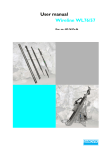
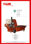
User manual
Wireline WL56/42
Doc. no.: WL56/42e.06
User Manual
Table of contents
1. Introduction
............................................................................................4
1.1 Description ...........................................................................................4
2. Safety Instructions
..............................................................................5
2.1 Recommendations ..............................................................................6
2.2 Wire Handling ......................................................................................7
2.2.1 Winding of wire .............................................................................7
3. Outer Core Barrel, complete
.......................................................8
3.1 Fitting of Outer Core Barrel ............................................................8
3.2 List of spare parts – Outer Core Barrel ........................................9
4. Inner Core Barrel, complete
.......................................................10
4.1 List of spare parts – Inner Core Barrel, complete ....................11
5. Core Barrel Head
..............................................................................12
5.1 List of spare parts – Core Barrel Head 601 222 714,
– Core Barrel Head with shut off valve 601 222 714-1 ...................13
6. Functional description for pumping
7. Free Falling Overshot
........................................15
......................................................................16
7.1 List of spare parts - Free Falling Overshot 601 222 731 ..........17
8. Safety Lowering Device for dry holes
.....................................18
8.1 List of spare parts – Safety Lowering Device for dry holes
601 222 287 ................................................................................................19
9. Overshot for Pumping In
...............................................................20
9.1 List of spare parts – Overshot for Pumping In 601 222 721 ...21
10. Stuffing Box
........................................................................................22
10.1 List of spare parts – Stuffing Box 601 222 -720-X, -866-X ....23
11. Wireline 56/42, Component Parts .........................................24
12. Recovery kit-Component Parts 501 217 116
13. Recovery Operation
...................26
......................................................................27
13.1 Reasons of breakage .......................................................................27
13.1.1 Wear ..........................................................................................27
2 · Doc. no.: WL56/42e.06
User Manual
13.1.2 Fatigue .......................................................................................27
13.1.3 Getting stuck .............................................................................27
13.2 First thing to do when... ................................................................28
13.2.1 ...drill string is broken (cut off) down the hole ......................28
13.2.2 ...core barrel or drill bit is so badly stuck that they ca
not be removed by the drill unit ........................................................28
13.2.3 …the whole drill string is stuck in the hole due to
sedimentation or cave in .....................................................................28
13.2.4 ...tools have fallen into the hole ..............................................28
13.2.5 …wire and hoses have snapped down the hole .....................28
13.3 Expanding recovery tap ................................................................29
13.4 Recovery taps ..................................................................................32
14. Cleaning of drill hole
.....................................................................33
Doc. no.: WL56/42e.06 · 3
Introduction
User Manual
1. Introduction
The Sandvik Wireline System (WL) is available in dimensions of 46, 56, 66
and 76 mm. There are two different versions of WL56, where
the differences are primarily the weight of the drill rod and the inner
dimension, which permit different core dimensions. The 66 and 76 mm
dimensions include a triple variant with an extra inner tube.
Table 1: Different Wireline Systems
System
Hole
dimension
Core
dimension
Tube ext./
int. dim.
Tube weight
kg/m
WL46
Ø47.0
Ø28.8
Ø43.2/35.2
3.9
WL56/39
Ø56.8
Ø39
Ø53.2/45.2
4.9
WL56/42
Ø56.8
Ø41.2
Ø53.2/47.2
3.8
WL66
Ø67.1
Ø50.5
Ø63.9/57.0
5.1
WL66-3
Ø67.1
Ø45
Ø63.9/57.0
5.1
WL76
Ø76.3
Ø57.5
Ø73.2/64.4
7.5
WL76-3
Ø76.3
Ø51
Ø73.2/64.4
7.5
WL103
Ø102.8
Ø80
Ø98/88.8
10.6
1.1 Description
WL56/42 is a thinwall Wireline System adapted to the metric system. This
makes it possible to switch between the T, TT and WL Systems whenever
necessary.
The WL System is intended to be used for drilling in all directions without
the need for extra accessories. An overshot is used to obtain the best results
from the system, which is designed to be pumped into the hole (see
chapters “Overshot for Pumping In” on page 20 and “Stuffing Box” on
page 22). This overshot can be used in all directions, even with a high
water pressure.
For recovery in drill holes inclined at an angle of more than 60o from the
horizontal plane there is a free falling overshot (see chapter “Free Falling
Overshot” on page 16), which is provided with wheels. The same overshot
can be fitted with a special lowering device for use in downward holes with
water loss, so-called dry holes.
The WL core barrels are available in lengths of 1.5 and 3.0 m, but can be
extended to 4.5 and 6.0 m, please contact Sandvik for further information.
Drill bits for WL56 are manufactured as standard with an external
diameter of 56.5 and reaming shell of 56.8 mm.
Remark
When drilling with an oversize bit and reaming shell an
oversized drill rod connection should be used.
4 · Doc. no.: WL56/42e.06
User Manual
Safety Instructions
2. Safety Instructions
!
Ì
WARNING
When handling Wireline it is important to inspect the wire
visually, since a broken wire can cause injury to personnel or
damage the equipment. When the wire starts to look
damaged it should be shortened.
!
Ì
WARNING
There is a risk of injury from the wire during Wireline
drilling. This risk is greatest between the Wireline windlass
and the top of the mast. Do NOT enter this area when the
wire is in operation. There is also a risk of getting trapped
round the drum, in the wire spreader on the drum, and at
the pulley on the mast. Remember that the wire can split up,
which can lead to severe cut injuries. Never grip the wire
when it is in motion.
!
Ì
WARNING
When handling Wireline the inner tube can release on
detachment and come sliding out of the hole at high speed.
!
Ì
WARNING
When the core barrel is emptied from the drill bit there is
a risk of injuring the hands and fingers. The core can come
sliding out from the core barrel at high speed. NEVER place
the hands and fingers under the core barrel, place them is
such a way that the core can pass without causing injury.
!
Ì
WARNING
The drill rods are exposed to a higher load and heavier
vibrations during upward drilling. The risk of drill rods
braking when they are worn is therefore increased. If the
rods break during the drilling the rod holder will be open,
which causes the rod string to slide out from the hole. For
this reason, place the panel at a safe distance from the
barrier.
!
Ì
WARNING
The risk of injury increases more than normal during upward
drilling.
Doc. no.: WL56/42e.06 · 5
Safety Instructions
User Manual
!
Ì
WARNING
Cuff wrenches must under NO CIRCUMSTANCES be used
on the rods when they are rotated by means of the machine.
They can come loose and injure the operator, or cause pinch
injuries on the hands and fingers.
!
Ì
WARNING
Remember to secure the machine in a reliable manner when
it is anchored to the rock. Make sure to inspect the
attachment during operation to make sure the machine does
not come loose.
!
Ì
WARNING
Remember that you should have the opportunity to reach, or
have regular contact with those around you if you should
become injured when using the machine.
2.1 Recommendations
• Check the threads on the drill rods regularly. If the threads are damaged
they can damage other rods they are attached to. Pay extra attention to
the water swivel tube.
• Make sure that the threads are properly engaged with each other before
the rods are screwed together by means of the machine.
• Make sure that the rod does not break during threading (rod support
and guides).
• Make sure to lubricate the threads.
Note
Always lubricate the drill rod threads with grease that is
suitable for high pressure. Special thread lubricant is best.
• Avoid rotating so fast that the threads are “knocked” together.
• Check that the threads are free from dirt and undamaged.
• The continuous feed pressure should not exceed 3.5 tons.
• Avoid too many tough shapening. Use a lower water flow instead for
hard rock.
• Make sure that lifting function on the machine functions during the rod
threading, and that the “float position” works.
• If the threading on one rod should get damaged during making of joint,
both rods should be replaced.
6 · Doc. no.: WL56/42e.06
User Manual
Safety Instructions
2.2 Wire Handling
2.2.1 Winding of wire
Wire with the lay to the left
WL-2
Wire with the lay to the right
Figure 1. Wire handling
Doc. no.: WL56/42e.06 · 7
Outer Core Barrel, complete
User Manual
3. Outer Core Barrel, complete
The core barrel drill rod adaptor (1) has tungsten carbide inserts so that it
can be guided up and therefore minimize the hole deviation. The core
barrel can be fitted with a top reamer (part no. 101 220 542) and guides in
the middle.
3.1 Fitting of Outer Core Barrel
The outer landing ring (LY) (4) is fitted in the adapter tube’s (5) female
thread, with the internal collar facing upwards.
The latch housing (3) locks the landing ring (4).
Remark
The landing ring should be replaced after drilling approx.
500 m.
The latching ring (2) is fitted on the latch housing’s (3) female thread.
The drill rod adaptor (1) locks the latching ring.
The latching ring can be reversed after a period of use if the edge has
become worn.
When extending the core barrel an outer tube coupling (6) or a reaming
shell (9) is fitted between the outer tubes.
The outer tubes are of standard lengths 1.5 m or 3.0 m (see table
“Extendable Outer Core Barrel WL56/42” on page 9).
On those occasions when the outer tube is taken up for inspection a careful
check should be made that the outer landing ring and latching ring are in
place and undamaged.
The inner tube is locked upwards in the outer tube in that the core barrel
head latches support the latching ring. The inner tube is fixed downwards
in that the outer landing ring has a smaller diameter than the core barrel
head’s landing ring.
The tensile force when breaking the core is transferred from the core lifter
case to the drill bit in that the inner tube connection is flexible in the axial
plane (the core lifter case “rests” on the bit). The play between drill bit and
core lifter case can be adjusted for different types of drilling.
Before recovery the core is broken and the core barrel lifted 3-6 m. This
prevents drill cuttings that drop back into the hole collecting inside the
outer tube.
WL-3
Freshing the inner tube to mismatch when sent back.
8 · Doc. no.: WL56/42e.06
User Manual
Outer Core Barrel, complete
3.2 List of spare parts – Outer Core Barrel
Table 2: List of spare parts, Outer Core Barrel
1
2
3
4
5
No.
Quantity
Part
Remarks
Part no.
1
1
Drill rod adaptor, right-hand
1.1
1
Drill rod adaptor, right-hand
2
1
Latching ring
601 222 701
3
1
Latch housing
601 222 702
4
1
Outer landing ring
601 222 703
5
1
Adaptor tube
6
1
Outer tube coupling
7
*
Outer tube, 1.5 m
L = 1 552 mm
601 222 704
7.1
*
Outer tube, 3.0 m
L = 3 052 mm
601 222 705
8
*
Extension tube, outer tube, 1.5 m
L = 1 552 mm
601 222 704
8.1
*
Extension tube, outer tube, 3.0 m
L = 3 052 mm
601 222 705
9
1
Reaming shell
10
1
Drill bit
601 222 700
TH thread
L = 331 mm
601 222 857
601 222 711
601 222 706
* Standard outer tube (7) also used as extension tube (8).
6
Table 3: Extendable Outer Core Barrel WL56/42
7
8
Length
(m)
Quantity
Outer tube
standard
Quantity
Extension
tube
outer tube
Part no.
compl.
tube
1.5
1
601 222 704
-
-
601 222 738
3.0
1
601 222 705
-
-
601 222 739
4.5/2
1
601 222 705
1
601 222 704
601 222 740
6.0/2
1
601 222 705
1
601 222 705
601 222 741
Table 4: Outer Core Barrel with TH thread connection
9
WL-4
10
Length
(m)
Quantity
Outer tube
standard
Quantity
Extension
tube
outer tube
Part no.
compl.
tube
1.5
1
601 222 704
-
-
601 222 858
3.0
1
601 222 705
-
-
601 222 859
4.5/2
1
601 222 705
1
601 222 704
601 222 860
6.0/2
1
601 222 705
1
601 222 705
601 222 861
Doc. no.: WL56/42e.06 · 9
Inner Core Barrel, complete
User Manual
4. Inner Core Barrel, complete
A standard inner tube is used to extend the inner tube (see table
“Extendable Inner Core Barrel WL56/42” on page 11).
Always use cuff wrenches when working with the inner tube (2) and core
lifter case (5). Check the function of the core lifter spring (4) after each
recovery. If the inner tube is clamped oval, or otherwise damaged, the inner
tube can stick in the drill rod or outer landing ring. A landing ring for the
core barrel head can be used to check that the inner tube has not been
deformed.
Table 5: Estimated times for pumping in Inner Core Barrel
System
Volume drill
rod
Speed with water
flow of 40 l/min.
Time to 100 m
with water flow of
40 l/min.
WL46/29
1.0 l/m
40 m/min.
2.5 min.
WL56/39
1.6 l/m
25 m/min.
4 min.
WL56/42
1.7 l/m
24 m/min.
4 min.
2.6 l/m
16 m/min.
6 min.
3.3 l/m
12 m/min.
8 min.
WL66/45
WL66/50.5
WL76/51
WL76/57.5
WL-5
The pumping in time for the inner core barrel is part of the total handling
time. If the Sandvik System with pumping of the inner tube or lifter is used
it is possible to obtain an indication of when they are in position. This
ensures significant time savings since the drilling or recovery of the inner
core barrel can be started immediately. How long the pumping takes
depends on how much water can flow in the gap between the core barrel
and hole wall. This time can be reduced by increasing the pressure of the
water, or increasing the gap between the drill rod and hole wall. If the gap
is increased between the drill rod and hole this increases the risk of
deviated holes.
10 · Doc. no.: WL56/42e.06
User Manual
Inner Core Barrel, complete
4.1 List of spare parts – Inner Core Barrel,
complete
Table 6: List of spare parts, Inner Core Barrel, complete
1
No.
Quantity
Part
Remarks
Part no.
1
1
Core barrel head
2
*
Inner tube 1.5 m
L = 1 637 mm
601 222 707
2.1
*
Inner tube 3.0 m
L = 3 137 mm
601 222 708
3
*
Extension tube, inner tube 1.5 m
L = 1 637 mm
601 222 707
3.1
*
Extension tube, inner tube 3.0 m
L = 3 137 mm
601 222 708
4
1
Core lifter spring, standard
601 222 709
5
1
Core lifter case
601 222 710
601 222 714
* Standard inner tube (2) can also be used as extension tube (3).
2
Table 7: Extendable Inner Core Barrel WL56/42
Length
(m)
Quantity
Inner tube
standard
Quantity
Extension
tube
inner tube
Part no.
compl.
tube
1.5
1
601 222 707
-
-
601 222 742
3.0
1
601 222 708
-
-
601 222 743
4.5
1
601 222 708
1
601 222 707
601 222 744
6.0
1
601 222 708
1
601 222 708
601 222 745
3
5
WL-6
4
Doc. no.: WL56/42e.06 · 11
Core Barrel Head
User Manual
5. Core Barrel Head
Core barrel head has part no. 601 222 714.
Core barrel head with shut off valve has part no. 601 222 714-1.
Check that the latches (2) move freely and that the O-ring (1) and tubular
pin (3) are undamaged.
When checking the latches the lifter tip is inserted in the core barrel head.
The back edge of the lifters should then be inside the outer dimension of
the latch housing. If not, the tubular pin is probably crooked or the hole in
the latch worn.
When fitting the release valve (8) the spring (9) must be turned with the
rivet from the release valve.
Note
Make sure that the cylindrical pin (10) does not catch in the
thread and can easily be moved in its slot.
Note
Lubricate the core barrel head with grease every time it is
taken up.
Use enough grease to ensure that fresh grease is pressed out through the
bearing housing (13). Oil in the release valve through the hole at the
landing ring (6). Wipe off all surplus grease.
If the release valve jams there is a reamer (part no. 300 025 325) to clean
the release valve seat.
WL-64
21 mm
The landing ring core barrel head is fitted so that the hole is turned
backwards on the valve housing (11). Fit the latch housing (4) [with spacer
washer (5)] on the valve housing, and tighten. Screw the landing ring core
barrel head to the latch housing, and tighten. It will now function as a lock
nut.
When fitting the bearing unit it should be noted that the thrust ball bearing
(12) must be turned correctly for the grease to pass through the bearing.
Note
The thrust ball bearing (12) washers have different hole
diameters. The washer with the smallest hole diameter is
fitted upwards.
To optimize drilling in different types of rock it may be necessary to adjust
the gap between the bit and core lifter case. This is done be releasing the
lock nut on the inner tube connection (25) and adjusting the gap between
the inner tube connection (25) and the lower bearing housing (23).
The recommended setting is 21 mm.
12 · Doc. no.: WL56/42e.06
User Manual
Core Barrel Head
5.1 List of spare parts – Core Barrel Head 601 222 714,
– Core Barrel Head with shut off valve 601 222 714-1
Table 8: List of spare parts, Core Barrel Head
2
No.
Quantity
Part
Remarks
Part no.
3
4
1
1
O-ring
29.2 x 3.0
300 012 687
5
2
2
Latch
3
2
Tubular pin
4
1
Latch housing
601 222 319
5
1
Spacer
601 222 312
6
1
Landing ring core barrel head
601 222 715
7
1
Stop screw
300 012 531
8
1
Release valve
601 222 344
9
1
Spring
601 222 378
10
1
Cylindrical pin
300 022 671
11
1
Valve housing
601 222 466
12
1
Thrust ball bearing
300 013 549
13
1
Upper bearing housing
601 222 465
14
1
Radial ball bearing
300 013 548
15
1
Washer
300 014 907
16
1
Spring
300 025 064
17
1
Bushing
601 222 313
18
1
Radial ball bearing
300 013 547
19
1
Washer
300 012 553
20
1
Nut
300 014 914
21
1
Quick coupling
300 027 153
22
1
Grease nipple
300 015 242
23
1
Lower bearing housing
601 222 717
24
1
Nut
25
1
Inner tube connection
601 222 716
26
*
Spacer
601 222 758
26.1
*
Shut off valve
601 222 756
2
6
7
8
9
10
601 222 310
4.0 x 28
300 015 966
11
26
12
13
14
15
16
17
18
19
20
KM 5
300 013 333
22
23
* A spacer is normally used, but it can be changed to a shut off valve.
24
25
WL-8
21
Doc. no.: WL56/42e.06 · 13
Core Barrel Head
14 · Doc. no.: WL56/42e.06
User Manual
User Manual
Functional description for pumping
6. Functional description for pumping
WL-50
In the core barrel head there is a release valve (8), which before pumping in
should be locked in a special pumping position. Insert a screwdriver in the
latch housing, press the release valve forward and turn a quarter of a turn.
The release valve will now be locked in its pumping position and the
pumping in of the inner tube can now be started. When the inner tube is in
position the water pressure increases powerfully and the flow of water is
stopped. This is an indication that the inner tube is in it locked position.
With the retention of the high water pressure for a few seconds the release
valve will be pressed forward and released from its locked position.
Figure 2. Core barrel head
WL-51
After the pump flow has been stopped and the water pressure completely
drained, the spring will press the release valve upwards. This forms a free
passage for the flushing water, and the pumping for the drilling can be
started.
Figure 3. Core barrel head
Doc. no.: WL56/42e.06 · 15
Free Falling Overshot
User Manual
7. Free Falling Overshot
Free falling overshot has part no. 601 222 731.
The numbers below, in bracket, correspon against the number in the table
““List of spare parts, Free Falling Overshot, WL56/42” on page 17”.
The overshot has a swivel (1, 4, 6) in its upper end, which prevents the
wire from twisting. A safety device [shear pin (3)] is built into the swivel
and is intended to break at approx. 1.5 tons. This is to eliminate the risk of
a cut wire being left in the hole.
Remark
When double shear pins are fitted the breaking point load
increases to approx. 3 tons.
The wire is fitted in the wire clamp (1) and locked with three stop screws
(2).
Fit the bearing shaft (6) in the bearing housing (4), then fix the wire clamp
(1) on the bearing shaft (6) by means of the [shear pin (s) (3)]. Lubricate
the surfaces between bearing housing and wire clamp with grease. The
bearing housing is then filled with grease before it is fitted on the wire
weight by means of the tubular pin (5).
The shear pins should be replaced at regular intervals.
WL-52
When the lifting tip (11) is led down in the core barrel head the latches are
released from the latching ring. When the tip has passed the latches the
inner tube is locked to the overshot, and the inner tube can be winched up
by means of the wire.
Figure 4. Core barrel head
WL-65
Note
The lifting tip should be replaced when the edge of the lifting
tip begins to be worn.
The lifting tip can if necessary be provided with a joint by fitting a ball
joint (See Table 9) between the lifting tip (10) and wire weight (9).
16 · Doc. no.: WL56/42e.06
User Manual
Free Falling Overshot
7.1 List of spare parts - Free Falling Overshot 601 222 731
Table 9: List of spare parts, Free Falling Overshot, WL56/42
2
1
2
3
4
5
6
7
No.
Quantity
Part
Part no.
1
1
Wire clamp
601 222 692
2
3
Stop screw
300 027 148
3
1
Shear pin
300 025 423
4
1
Bearing housing
601 222 688
5
2
Tubular pin
300 015 732
6
1
Bearing shaft
601 222 693
7
3
Wheel
601 222 718
8
3
Stop screw
300 010 699
9
1
Wire weight
601 222 687
10
1
Lifting tip
601 222 217
8
Table 10: List of spare parts, Ball joint 601 222 462
9
8
No.
Quantity
Part
Part no.
11
1
Top joint
601 222 452
12
1
Steel ball
300 027 125
13
1
Spring
300 027 124
14
1
Tubular pin
300 015 949
15
1
Lower link
601 222 463
7
8
11
7
12
13
5
14
15
WL-67
10
Doc. no.: WL56/42e.06 · 17
Safety Lowering Device for dry holes
User Manual
8. Safety Lowering Device for dry holes
For dry holes there is a safety lowering device, which
is fitted on the standard overshot.
When the inner tube needs to be lowered into a dry
hole, the lowering device for dry holes is fitted to the
free falling overshot. The overshot is inserted into
the core barrel head so that the balls (6) sit in the
groove for the latches on the core barrel head.
The inner tube is winched down in the rod string
and when the inner tube is in place, the latches lock
as usual and the overshot can be disengaged and
brought up.
Once the drilling is complete, the lowering device is
detached from the overshot and the inner tube can
be retrieved normally.
WL-66
Safety
Lowering
Device
18 · Doc. no.: WL56/42e.06
User Manual
Safety Lowering Device for dry holes
8.1 List of spare parts – Safety Lowering Device
for dry holes 601 222 287
Table 11: List of spare parts, Safety Lowering Device
1
No.
Quantity
Part
Remarks
Part no.
1
1
Extension socket
2
1
Adjusting screw
3
1
Spring
300 021 312
4
1
Plunger
601 222 137
5
1
Spring housing
601 222 193-1
6
2
Steel ball
300 021 313
7
1
Hood
601 222 139
8
1
Tubular pin
601 222 251
SK6SS 12 x 20
FRP 3 x 14
300 021 311
300 027 261
2
3
4
5
7
8
WL-17
6
Doc. no.: WL56/42e.06 · 19
Overshot for Pumping In
User Manual
9. Overshot for Pumping In
Overshot for pumping in has part no. 601 222 721.
The overshot has a swivel (1, 4, 5) in its upper end, which prevents the
wire from twisting. A safety device [shear pin (3)] is built into the swivel
and is intended to break at approx. 1.5 tons. This is to eliminate the risk of
a cut wire being left in the hole.
Remark
The wire is fitted in the wire clamp (1) and locked with three stop screws
(2).
The bearing shaft (5) is fitted together with the bearing housing (4) and
lubricated internally with grease. The bearing shaft is locked with a circlip
(6). The shaft should be able to turn without problem, after which the wire
clamp can be fitted by means of the shear pin(s).
The shear pins should be replaced at regular intervals.
The guide (8) and seal (7) are fitted on the valve housing (9), and the
bearing housing (4) is tightened. The seal is self-adjusting.
The seal on the overshot for the pumping in seals to the drill rod. This
means that a check should be made to see that the drill rods are free from
rust on the inside and that no rod joints are damaged. Rusty or damaged
rods will damage the seal.
The overshot is provided with a valve that opens automatically on
recovery.
The O-rings (10) are fitted on the valve housing (9) and lubricated with a
thin grease. The seal housing (12), spring (14) and shaft (15) are pressed
together with the valve housing, and tubular pin (11) 8 x 28 is fitted.
Finally the lifting tip is fitted and locked with the tubular pin (13) 8 x 40.
When the overshot lifting tip is inserted into the core barrel head, the
latches will be released from the locking ring. Once the lifting tip has
passed the latches, the inner tube is locked to the overshot and the inner
tube can be winched up using the wire.
WL-52
WL-12
When double shear pins are fitted the breaking point load
increases to approx. 3 tons.
Figure 5. Core barrel head
Note
When the edge of the lifting tip begins to be worn it should
be replaced.
20 · Doc. no.: WL56/42e.06
User Manual
Overshot for Pumping In
9.1 List of spare parts – Overshot for Pumping In
601 222 721
Table 12: List of spare parts, Overshot for Pumping In
2
2
1
2
3
4
5
6
No.
Quantity
Part
Remarks
1
1
Wire clamp
601 222 729
2
3
Stop screw
300 027 148
3
1
Shear pin
300 025 423
4
1
Bearing housing
601 222 722
5
1
Bearing shaft
601 222 728
6
1
Circlip
7
1
Sealing ring
601 222 723
8
1
Guide
601 222 724
9
1
Valve housing
601 222 725
10
2
O-ring
19.1 x 1.6
300 012 646
11
1
Tubular pin
8 x 28
300 015 732
12
1
Seal housing
13
1
Tubular pin
14
1
Spring
300 010 966
15
1
Shaft
601 222 727
16
1
Lifting tip
601 222 217
SgH20
Part no.
300 027 294
7
8
9
601 222 726
8 x 40
300 015 974
10
11
12
13
14
15
WL-13
16
Doc. no.: WL56/42e.06 · 21
Stuffing Box
User Manual
10. Stuffing Box
Stuffing box has part no. 601 222 720-X.
The stuffing box can be fitted directly on the drill rod by screwing it on by
with a pair of tongs.
We recommend that the sealing box, water hose, pump-in overshot and a
750 mm drill rod are fitted together to form a single unit, a “loading tube”.
This simplifies handling when retrieving the inner tube. The loading tube
can be screwed on the drill string by means of the machine as soon as the
water swivel tube has been removed. The water is connected as per
“Figure 6. Proposal for water handling” one page 22.
The stuffing box is designed so that the pipe string can be rotated during
the pumping.
No need for
surface use
To stuffing box
To water
swivel
tube
From water pump
WL-14
1
3
4
Drainage
Figure 6. Proposal for water handling
Table 13: List of spare parts, Stuffing Box
22 · Doc. no.: WL56/42e.06
No.
Quantity
Part
Remarks
Part no.
1
1
2
3
1/2"
300 013 227
3
2
3/4"-1/2"
300 013 056
4
6
1/2"-1/2"
300 013 048
5
3
1/2"
300 013 132
803 908 127
WL-16
2
User Manual
Stuffing Box
10.1 List of spare parts – Stuffing Box 601 222 720-X, -866-X
Table 14: List of spare parts, Stuffing Box
1
2
3
4
5
6
7
No.
Quantity
Part
Remarks
Part no.
1
1
Screw
See Table 15 on page 23
2
1
Seal
See Table 15 on page 23
3
1
Spacer
See Table 15 on page 23
4
1
Seal housing
601 222 635
5
1
Tredo washer
300 012 614
6
1
Adaptor
300 013 048
7
1
O-ring
29.2 x 3.0
300 012 691
8
2
Tubular pin
5 x 40
300 020 641
9
1
Connector
9.1
1
Connector
TH thread
601 222 867
10
1
Drill rod
L = 750 mm
601 222 733
10.1
1
Drill rod
TH thread
L = 750 mm
601 222 856
601 222 730
8
9
Table 15: Stuffing Box, complete
Wire mm
Screw
Spacer
Seal
Stuffing box
4.4 (11/64")
601 222 638-1
601 222 637-1
601 222 499
601 222 720-1
4.8 (3/16")
601 222 638-2
601 222 637-2
601 222 501
601 222 720-2
6
601 222 638-3
601 222 637-3
601 222 543
601 222 720-3
Table 16: Stuffing Box, complete with TH thread 601 222 866-X
Wire mm
Screw
Spacer
Seal
Stuffing box
4.4 (11/64")
601 222 638-1
601 222 637-1
601 222 499
601 222 866-1
4.8 (3/16")
601 222 638-2
601 222 637-2
601 222 501
601 222 866-2
6
601 222 638-3
601 222 637-3
601 222 543
601 222 866-3
WL-15
10
Doc. no.: WL56/42e.06 · 23
Wireline 56/42, Component Parts
User Manual
11. Wireline 56/42, Component Parts
Drill bit 56.5 - 41.2, Reaming shell 56.8, Drill rod 53.2 - 47.2 mm
Table 17: Wireline 56/42, Component parts
24 · Doc. no.: WL56/42e.06
Component Parts
Part no.
Part no.
TH thread
Core barrel, complete WL56/42 x 1500
601 222 746
601 222 862
Core barrel, complete WL56/42 x 3000
601 222 747
601 222 863
Core barrel, complete WL56/42 x 4500
601 222 736
601 222 864
Core barrel, complete WL56/42 x 6000
601 222 737
601 222 865
Outer tube, complete WL56/42 x 1500
601 222 738
601 222 858
Outer tube, complete WL56/42 x 3000
601 222 739
601 222 859
Outer tube, complete WL56/42 x 4500
601 222 740
601 222 860
Outer tube, complete WL56/42 x 6000
601 222 741
601 222 861
Inner tube, complete WL56/42 x 1500
601 222 742
Inner tube, complete WL56/42 x 3000
601 222 743
Inner tube, complete WL56/42 x 4500
601 222 744
Inner tube, complete WL56/42 x 6000
601 222 745
Core barrel head, complete WL56
601 222 714
Core barrel head with shut off valve, complete WL 56
601 222 714-1
Free falling overshot for downward hole, complete
601 222 731
Ball joint, complete
601 222 462
Lowering device for dry hole, complete
601 222 287
Overshot for pumping in, complete
601 222 721
Stuffing box for pumping in, complete
601 222 720-X
Water handling
803 908 128
Water swivel
501 012 143-2
Adapter, water swivel
501 222 813
601 222 888
Drill rod WL56/42, 53 x 750 mm
601 222 733
601 222 856
Drill rod WL56/42, 53 x 1500 mm
601 222 713
601 222 855
Drill rod WL56/42, 53 x 3000 mm
601 222 712
601 222 841
601 222 866-X
User Manual
Wireline 56/42, Component Parts
Component Parts
Part no.
Adapter drill rod WL53/47 pin x WL53/45 box
501 222 804
Adapter drill rod WL53/45 pin x WL53/47 box
501 222 803
Adapter drill rod WL53/47 box x WL43 pin
501 222 810
Adapter WL53/47 box x 42 pin
501 222 811
Adapter WL53/47 box x 50 pin
501 222 812
Adapter WL53/47 pin x WL43 box
501 222 813
Adapter WL53/47 pin x 42 box
501 222 814
Adapter WL53/47 pin x 50 box
501 222 815
Adapter drill rod WL53/47 TH pin x WL53/45 box
501 222 889
Adapter drill rod WL53/45 pin x WL53/47 TH box
501 222 890
Adapter drill rod WL53/47 TH box x WL43 pin
501 222 891
Adapter WL53/47 TH box x 42 pin
501 222 892
Adapter WL53/47 TH box x 50 pin
501 222 893
Adapter WL53/47 TH pin x WL43 box
501 222 894
Adapter WL53/47 TH pin x 42 box
501 222 895
Adapter WL53/47 TH pin x 50 box
501 222 896
Cuff wrench WL56 inner tube
501 115 047
Cuff wrench WL56 outer tube
501 115 048
Gripping pliers
501 115 035
Tool kit, including:
601 222 183
- Hex key 3.5 mm
- Pin punch Ø4, Ø8 mm
- Hook wrench Ø38, Ø58 mm
- Sleeve NV 22 mm, connection 1/2"
- Long screwdriver
- Tool bag
Wrench for inner tube connection
601 222 590-2
Assembly tool
601 222 484-2
Hand reamer for valve housing
300 025 325
Doc. no.: WL56/42e.06 · 25
Recovery kit-Component Parts 501 217 116
User Manual
WL-68
12. Recovery kit-Component Parts
501 217 116
Table 18: Recovery kit 501 217 116
26 · Doc. no.: WL56/42e.06
No.
Quantity
Part
Part no.
1
1
Drillrod tap WL53/47 RH connection 33.5 box
501 217 115
2
1
Drillrod tap WL53/47 LH connection 33.5 box
501 217 115-V
3
1
Drillrod tap Ø42 mm
501 217 001
4
1
Drillrod tap, expanded WL63
501 217 113
5
1
Extension tube recovery kit
501 217 101
6
1
Sub WL53 box x Z 56 box
501 217 098
7
1
Sub 29.5/27.5 pin x M24 x 1.5 pin
501 222 741-2
8
1
Sub WL53/47 box x 50 pin
501 222 812
9
1
Drill bit Z 56
100 011 782
10
1
Drill bit 34/23
100 024 583
11
1
Tool bag
300 027 167
12
1
Sub WL53/45 pin x WL53/47 box
501 222 803
User Manual
Recovery Operation
13. Recovery Operation
Every core driller will sooner or later experience the situation when drilling
tools are either broken down or stuck in the hole. In such cases no drilling
can proceed before the string is recovered.
13.1 Reasons of breakage
13.1.1 Wear
Drill rods and other exposed parts of the drill string wear against the hole
wall during drilling. The cuttings in combination with flush water will also
contribute to this wear. The rods will wear down to a point where they will
not be able to resist the torques nor the longitudinal forces they are
exposed to.
13.1.2 Fatigue
Drill rods and drill bits are constantly exposed to heavy loads and forces.
The life of the equipment is limited by its fatigue resistance. If the nominal
life of the drill string is exceeded the risk of breakage is rapidly increased.
The life can be considerably reduced if the through faulty usage or
maintenance. Heavy deviation of the drill holes also reduces life of the drill
string due to the combination rotation/bending.
13.1.3 Getting stuck
Common cause of getting stuck:
1. Poor evacuation of cuttings. The cuttings from the bottom of the hole
has to be transported to the surface by means of flush water. Too low
flush speed makes the cuttings pack up against the drill rods which
ultimately will result in getting stuck.
2. Leakage of the drill rod joints makes the flushing of the lower part of
the drill string insufficiently flushed.
3. Cracks and fractures in the rock may result in loss of flush water. Hence
the cuttings will cease to move upwards and it will sediment in the hole.
4. Cracks may also cause the drill bit to get stuck during drilling.
5. Lack of flush water due to faulty water pump or operator error. The
drill string will get stuck in a matter of seconds due to melting of the
drill bit.
Doc. no.: WL56/42e.06 · 27
Recovery Operation
User Manual
13.2 First thing to do when...
13.2.1 ...drill string is broken (cut off) down the hole
The drill string still attached to the drill unit is taken out of the hole. The
breaking point is studied and suitable method is then chosen to recover the
drill rods still down in the hole.
13.2.2 ...core barrel or drill bit is so badly stuck that they
can not be removed by the drill unit
The tools stuck in the hole can be drilled (cleaned) away with drill bits.
Swiveled parts stuck in the hole will rotate and therefore it may sometimes
be nessesary to pour cement down the hole prior to the cleaning.
13.2.3 …the whole drill string is stuck in the hole due to
sedimentation or cave in
It may be possible to save the drill string by drilling over it with a larger
dimension.
13.2.4 ...tools have fallen into the hole
The two most common methods are to lower recovery tools — usually
specially made for the specific purpose — or to drill away the tools.
13.2.5 …wire and hoses have snapped down the hole
It is usually possible to lower a ”spear” with hooks and rotate it. This will
cause the hose/wire to twine around the spear.
28 · Doc. no.: WL56/42e.06
User Manual
Expanding recovery tap
14. Expanding recovery tap
The expanding recovery tap should be used if one of the drill rods is cut off
in the hole. It is also an alternative when a drill string or parts of it is
dropped down the hole and can not be “picked up” by remaining drill
rods. The expanding recovery tap is a recovery tool for pulling up drill
rods stuck in the hole without rotation. It should be not be used for
unscrewing drill rods.
1. Assembly
The expanding recovery tap is attached to drill rods of the same dimension
as the string stuck in the hole. An adaptor shall be used in between the drill
rod and the expanding recovery tap.
1
Table 19: Expanding recovery tap parts
2
No.
Part
1
WL Drill rod
2
Sub
3
Expanding recovery tap
FG-1
3
Doc. no.: WL56/42e.06 · 29
Expanding recovery tap
User Manual
2. Lowering
Before the lowering of the tool, the expander should be
fixed in “lowering position”.
FG-3
The expander is
turned until the
steering pin is in a
position which will
enable the expander
to move up and down.
FG-2
Lowering position
3. Lowering towards the “lost” drill rods
FG-4
The expanding recovery tap is inserted a maximum of 250
mm into the “lost” drill string.
30 · Doc. no.: WL56/42e.06
User Manual
Expanding recovery tap
4. Recovery of the “lost” drill string
When the recovery tap shaft is being pulled backwards it
will make the lower part expand inside the “lost” drill
string.
Table 20: Maximum pulling force without rotation
Pulling force (kg)
WL46
WL56
WL66
WL76
8000
12000
20000
24000
Note
Do not rotate the drill string when the tool is
being pulled back.
Note
FG-5
It may happen that the drill string is so badly stuck that the
expander slides out of the drill string. In such a case
another recovery tool should be used.
5. Release of the expanding recovery tap
If max allowed pulling force is reached, the expander
should be released. This is done by pushing forward and
turning the (fishing) drill string 30° RH-turn (see the
picture to the left).
FG-7
FG-6
The expanding recovery tap can now be released and the
next recovery alternative should be tried.
Doc. no.: WL56/42e.06 · 31
Recovery taps
User Manual
15. Recovery taps
The recovery tap should be used when a drill string is stuck or broken in
the hole and when attempts to recover with the expanding recovery tap
have failed. There are two types of recovery taps – one right hand threaded
(RH) and one left hand threaded (LH). The right handed tap can be
attached to three different set-ups of drill rods:
1. The existing drill string. With this set-up it is possible to screw the
recovery tap only as far down the (stuck/broken) drill rod as the
adaptor on top of the recovery tap permits. If the edge of the adaptor
has reached the broken drill rod without the recovery tap gripping,
another method of recovery must be used.
2. Using a smaller O.D. drill rod in between the existing drill string and
the recovery tap. In this way the recovery tap is permitted to go deeper
inside the (stuck/broken) rod.
3. Using a smaller O.D. drill string whose threads fit directly with the
recovery tap.
Table 21: Drill rod for the different systems
FG-8
Drill rod
WL46
WL56
WL66
WL76
33.5
33.5
50
50
The RH recovery tap can be combined with a Z-cleaning bit to drill clean
the hole from caved in rock.
The left handed (LH) tap is for recovering drill rods one by one when
attempts to pull out the drill string have failed. These rods may not be
stuck themselves, but joint with the drill rod or core barrel that is stuck
deeper down in the hole. As the un-screwing is done with left hand
rotation, the LH-tap requires a left hand (LH) threaded drill string. The
LH tap can not be combined with the Z-cleaning bit that is included in the
recovery kit.
Recovery tap with Z-cleaning bit
FG-11
FG-9
32 · Doc. no.: WL56/42e.06
FG-10
Alternative 2 and 3
Alternative 1
User Manual
Cleaning of drill hole
16. Cleaning of drill hole
When tools are so badly stuck that they can not be recovered from the
hole, a cleaning bit (Z) should be used to drill these tools away. In some
cases it is necessary to pour cement in the hole to stop swivelled parts such
as a core barrel head from rotating when the Z-bit is used.
The cleaning bit is attached onto the WL drill rods by means of a sub.
If there is a problem with vibrations, there are specific drill rods (Z-drill
rods) that can fitted directly on to the Z-bit.
Table 22: Cleaning of drill hole parts
1
No.
Part
1
WL-drill rod
2
Sub
3
Z-cleaning bit
2
FG-13
FG-12
3
The Z-cleaning bit can be combined with another drill bit if it becomes
necessary to increase the cutting area to cut away the broken tools.
1
Table 23: Cleaning of drill hole parts
2
No.
Part
1
WL-drill rod
2
Sub
3
Extension rod for TV Z bit
4
Z cleaning bit
5
TV Z bit
3
5
FG-15
FG-14
4
Doc. no.: WL56/42e.06 · 33
Cleaning of drill hole
34 · Doc. no.: WL56/42e.06
User Manual