1
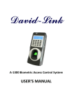
March 2010
FASTflo WHC56
Service Manual
Working towards
a cleaner future
March 2010
WHC56
Service Manual
•
•
•
This manual must be read by Service personnel repairing the above appliance models.
Take this manual with you when attending Service study
meetings.
The specifications and contents of this manual may
change at any time without prior notification.
Never short-circuit any safety devices
CONTENTS
Overview of Condensing Gas Water Heater ............................................................... 2
Structural Cross-section of Operation Unit ................................................................. 3
Principle of Operation ................................................................................................. 4
Operation Panel, Remote Control .............................................................................. 6
Initital Operation ......................................................................................................... 7
Setting Hot Water Temperature .................................................................................. 8
Sequence ................................................................................................................. 10
Wiring Diagram and Inspection Flowchart ............................................................... 12
Checkpoints and Measures if a Breakdown Occurs................................................. 14
Maintenance ............................................................................................................. 25
Installation ................................................................................................................ 37
Specifications ........................................................................................................... 39
Dimensions .............................................................................................................. 40
KS-09-0003
Overview of Condensing Gas Water Heater
This water heater is a high efficiency, fully condensing appliance. Unlike a traditional water heater, a condensing
type captures heat from the exhaust gas and uses it to preheat the incoming cold water as it passes through the
secondary heat exchanger as illustrated below.
Conventional
type
Condensing
Gas Water
Heater
Exhaust
About 200°C
Exhaust
About 50°C
Water is heated
using the exhaust
gas which is about
200°C.
Secondary heat exchanger
Combustion gas
About 200°C
Combustion gas
About 200°C
Primary heat exchanger
Primary heat exchanger
Drain Trap
Condensate
Hot water
Gas
Cold water
Hot water
Gas
Cold water
The condensing gas water heater
discharges condensate.
When heat from the exhaust gas is collected
within the secondary heat exchanger,
condensation occurs from moisture in the
exhaust gas and the resulting water is
discharged from the drain pipe (approx. 100cc/
min maximum). It is not a water leak. Do not
plug or block the drain line as it must always be
allowed to freely flow.
Drain pipe
(Installation example)
Condensate
comes out from
here.
The condensing gas water heater
tends to show white steam.
After the exhaust gas passes through the
secondary heat exchanger, it becomes low in
temperature and moisture rich which tends to
produce steam at the vent discharge terminal.
This is a normal occurrence.
–2–
During combustion, white
steam may often be seen.
This is normal.
Structural Cross-section of Operation Unit
< WHC56, LWHC56>
Air inlet
Flue collar
Secondary heat exchanger
Primary heat exchanger
Frost sensing switch
High-limit switch
Drain trap
Water level electrode
(Front side:No.2)
(Back side:No.1)
Thermal fuse
Ignition electrode
Main flow control valve
Heat exchanger
thermistor
Manifold
Igniter
Flame rod
PCB
Gas solenoid valve
Bypass flow control valve
Gas proportioning valve
Fan motor
Current leakage
safety device
Water outlet thermistor
Remote controller
terminal
Transformer
Gas inlet
Hot water outlet
Condensate drain outlet
Water filter
Power cord
Cold water inlet
Water flow sensor
Water inlet thermistor
–3–
Principle of Operation
Exhaust
High-Limit Switch
Frost Sensing Switch
Anti-Frost Heater
Secondary Heat Exchanger
Water Level Electrode 2
Water Level Electrode 1
High-Limit Switch
Primary Heat Exchanger
Thermal Fuse
Igniter
Main Flow Control Valve
Ignition Electrode
Flame Rod
Burner
Heat Exchanger Thermistor
Drain trap SET
Bypass Flow Control Valve
Primary Gas Solenoid Valve
Gas Proportioning Valve
Water Inlet
Thermistor
Gas Solenoid Valve 3
Gas Solenoid Valve 1
Air Supply
Gas Solenoid Valve 2
Impeller
Fan Motor
Rotation Frequency Sensor
Water Flow Sensor
PCB
Water Outlet
Thermistor
Water Drain Valve
Transformer
Current leakage
safety device
AC230V
Water Drain Valve
Water Filter
Water Drain Valve
Over Pressure Relief Valve
Water Drain Valve
Gas
Hot Water
Supply
Water Supply
Hot Water
Fixture
–4–
Water Outlet
(Condensate)
Explanation of operation
1.Using hot water
(1) Turn the ON/OFF
button on the remote controller to ON.(The ON/OFF
button will
turn on the light.)
(2) Open the hot water valve to be used. If the water flow sensor detects a water flow above the minimum operation water flow volume, pre-purge(purging gas remaining in the combustion chamber
before ignition) will be carried out for a fixed duration of time. After this the gas solenoid valve will
open, the ignition device will activate, and ignition will take place in the burner. (The bypass flow
control valve is always waiting in the normally "open" position.)
(3) When the flame rod(flame sensor) detects a flame, the ignition device will stop sparking.
(4) The hot water temperature will automatically be adjusted to the temperature selected with the temp.
button.
(5) Close the hot water valve that was used.
(6) When the water flow sensor detects a water flow below the minimum operation water flow, the gas
solenoid valve will close and the flame will go out. Post-purge(purging gas remaining in the combustion chamber after the flame goes out) will be carried out for a fixed duration of time, and then
the unit will stop.
(7) After using, the ON/OFF
button on the remote controller should be turn OFF.
(The ON/OFF
button will turn off the light.)
2. Error Codes
If by any chance the flame rod does not detect a flame or the high limit switch activates, the gas solenoid valve will close and extinguish the flame.
The display will show an error message to inform you of safe operation.
The safe operation reset procedure is to press the ON/OFF
button so it turns OFF, and then
press it again to turn it ON.
3. Miscellaneous
Before going to bed or at other times when the unit will not be used for a prolonged period of time, be
sure to press the ON/OFF
button on the remote controllers, make sure that the display has
gone off, and then close the primary gas solenoid valve.
–5–
Operation Panel, Remote control
Main Remote Controller (RC-7508M)
Part number B285
Power On/Off Button / Lamp
Display
Selection Button
Set Button
Speaker
PLEASE NOTE THAT ONE REMOTE CONTROLLER IS REQUIRED PER INSTALLATION
–6–
Initial Operation
Before the first use of your water heater, make the following preparations.
Follow steps
1
1 through 4.
Open the water supply valve.
OPEN
CLOSED
2
Open a hot water fixture to confirm that
water is available, and then close the fixture
again.
Hot water fixture
3
Open the gas supply valve.
4
Turn on the power.
–7–
Setting Hot Water Temperature
On this Display
1
Operation
Description
* The ON/OFF
Press the
is lit.
button
ON/OFF
to turn it “On”.
2
Use the
buttons
Here
(Eg.: 40°C)
WARNING
to adjust the
temperature.
While the shower is being used, no one other than the user
should change the temperature, the power switch must not be
turned “off”.
This is to prevent scalding if the temperature rises. Conversely, if the temperature drops or the power switch is
turned “off”, the user may be upset when the water suddenly becomes much colder.
–8–
Approximate hot water conditions
37 38 39 40 41 42 43 44 45 46 47 48 50 55 60 65 70 75 80
Set the maximum temperature to suit your own preference.
Washing
dishes, etc.
Shower, hot water supply, etc.
Hot water supply, etc.
High temperature
• Hot water temperatures are approximations, and may differ from actual temperatures depending on external
factors, such as the season and length of piping involved.
• When low temperatures are set (for washing dishes, etc.), if the ambient water temperature is already quite
high, it may be difficult to ensure the resultant water temperature is as per the setting.
• When the hot water temperature is adjusted using thermostat-controlled water mixing valves, set the temperature
on the remote controller to about 10°C higher than that required to ensure the appropriate temperature.
When setting high temperatures (60 - 80°C)
• When a high temperature is set, the readout on the right is
shown.
• Please check the temperature displayed before using any hot
water.
Be especially careful using any hot water after any previous
setting of between 60 - 80°C.
–9–
Here
(Eg.: 60°C)
Temperature display
flashes for about 10
seconds to indicate
high temperature.
Sequence
Operation
Water heating
Shutdown p
Connect power
Fix problem
Hot water tap C
Bypass flow control valve
and main flow control valve
move to initial position setting
Current leakage safety
device normal
Disconnect power
Water flow senso
NO
< 2.0 L/mi
ON/OFF lamp turns OFF
The unit will continue to operature with
the code blinking.
ON/OFF button turn ON
Flame lam
goes off
Gas proportionin
Error code stops flashing
closes
NO
5 years or more
of use
ON/OFF lamp (green) lights
Main flow control valve opens
Self-diagnosis
Normal combustion
possible
Y
Warning indication
YES
Primary gas so
Turn power Off
valve close
YES
Gas solenoid
closes
90
Gas solenoid
closes
Warning indication
YES
NO
Self-diagnosis
Combustion possible
Maximum output limited
NO
YES
Warning indication
Gas solenoid
closes
10
90
Fan motor post
Main flow co
NO
Self-diagnosis
Combustion possible
valve opens ful
99
YES
Fan motor s
1
Overheat prevention
device (Thermal fuse) normal
(Less than 184°C)
NO
14
Has 6min. pa
since hot water f
closed
YES
Y
Warning indication
2
Main flow
control valve operating
normal
NO
65
Heat
exchanger ther
< 40°C
YES
Warning indication
3
Bypass flow
control valve operating
normal
NO
Bypass flow c
66
Setting 55°C or higher
5
NO
YES
6
Bypass flow control
valve closes
3
valve closes
Stop hot water demand
YES
7
Water inlet thermistor
open or shorted
31
Water outlet thermistor
open or shorted
32
Heat exchanger thermistor
open or shorted
*1
If the inlet temp is less than 50°C
or if the following statements
about K are true , the inlet temprature
will be normal (YES).
K>
Ap
Total
Set tempe
33
K
Hot water demanded
Circuit board
abnormality
70
Abnormal gas solenoid
valve drive circuit
71
*2
4
NO
Water flow sensor detects
> 2.5 L/min.
8
YES
Initial check
normal
NO
72
Drain trap Blockage
29
20
YES
*1
Inlet water high
temperature check
Normal
5
Flame rod circuit
abnormality
(1μA or more)
Fan motor stops
NO
YES
*3
(Fan abnormality)
Fan motor ON
9
Fan speed
(target 200 rpm)
NO (After 60 sec)
kW/h
Gas solenoid
valve 1
ON
ON
Gas solenoid
valve 2
ON
Gas solenoid
valve 3
ON
ON
When the present fan speed is 500rpm more or less
(Ignition failure)
NO
Ignition
(9 times or less)
11
NO
(Flame rod)
YES
YES
Extinction
11
kW/h
61
YES
10
Over
18.1
Over
33.3
Out put
12
Igniter sparks
YES
NO (3rd)
High limit switch
is normal
Primary gas solenoid
12
18 (High-limit switch)
valve opens
20
Gas solenoid valve 1
13
opens
Gas solenoid valve 2
14
Primary gas solenoid
opens
valve closes
Gas proportioning valve
15
Gas solenoid valve 1
opens
closes
Primary gas solenoid
Gas solenoid valve 2
valve closes
closes
16
Flame rod
detects > 1μA
Gas solenoid valve 1
Gas proportioning valve
NO
closes
closes
Gas solenoid valve 2
closes
Igniter stops sparking
YES
Gas solenoid valve 3
closes
Gas proportioning valve
Flame lamp
lights
closes
Gas solenoid Valve 3
Igniter stops sparking
Flame lamp
goes off
closes
Flame Lamp
goes off
Gas solenoid valve 3
17
opens or closes
(as necessary) *2
14
At max combustion, is
outlet water temp. less
31
33
90
29
NO
than setting
16
YES
2
Main flow control valve
activates
1
Overheat prevention
device (Thermal fuse)
triggered (184°C or more)
Flow is adjusted
8
NO
Safety device triggered
32
5
Water inlet thermistor
open or shorted
6
Flame rod does
not detect a flame
(0.5μA or less)
is too high
YES
– 10 –
20
Heat exchanger
thermistor
open or shorted
6
Outlet water temp.
99
61
7
Water outlet thermistor
open or shorted
Abnormal combustion
Drain trap Abnormality
(check for blockage and
electrode connections)
10
Fan speed
abnormality
*3
Using terms is equivalent
to more than 10 years
Shutdown procedure
Hot water tap CLOSED
Water flow sensor detects
NO
< 2.0 L/min.
YES
Flame lamp
goes off
Gas proportioning valve
closes
Primary gas solenoid
valve closes
Gas solenoid valve 1
closes
Gas solenoid valve 2
closes
Gas solenoid valve 3
closes
Fan motor post purge
Main flow control
valve opens fully
Fan motor stops
Has 6min. passed
since hot water fixture
closed
NO
YES
Heat
exchanger thermistor
< 40°C
NO
Bypass flow control
valve closes
*1
If the inlet temp is less than 50°C
or if the following statements
about K are true , the inlet temprature
will be normal (YES).
K>
Approx. 1.6 x 25
+ water inlet temperature (°C)
Total water flow (L/min.)
Set temperature Less than 53°C
K
*2
*3
58°C
53°C or more
Set temp + 10°C
Over
33.3
Over
18.1
Over
11.7
Over
6.3
kW/h
kW/h
kW/h
kW/h
Gas solenoid
valve 1
ON
ON
ON
Gas solenoid
valve 2
ON
Gas solenoid
valve 3
ON
Out put
ON
ON
When the present fan speed is 500rpm more or less than target speed.
– 11 –
Over
2.8
kW/h
ON
ON
– 12 –
(VCC)
3
2
1
FM
W
V
V
W
LS
SM
LS
FROST SENSING
SWITCH
W
BK
Y/G
B5
W
W
W
W
2
1
2
1
W
W
EARTH EARTH
BR
BL
BL
BL
BL
1
1
BL
2 1
EARTH
Y/G
POWER CORD
Y/G
<AC230V>
1
2
3
BL
BL
BK
V
8
7
6
5
4
3
2
1
G
O
R
Y
BL
W
BK
V
W
G
O
R
Y
BL
8
7
6
5
4
3
2
1
BK
W
W
W
G
BL
1
2
BK
V
W
G
O
R
Y
BL
BK
V
W
G
O
R
Y
BL
2
1
W
W
W
W
W
W
W
W
R
BL
BL
BL
4
3
2
1
BL
BL
BR
Y
BL
R
BL
BR
CURRENT
LEAKAGE
SAFETY DEVICE
(GFCI)
BK
R
W
W
W
W
2
1
BR
Y
BL
R
W
RC TERMINAL
IGNITER
IG
BL
W
G
BR(Vs)
Y(FG)
BL(GND)
R(Vcc)
(GND)
(VCC)
(Fully open)
(GND)
(VCC)
SYSTEM CONTROLLER
SC-201-6M INT
(OPTIONAL)
HIGH-LIMIT SWITCH
(FOR FLUE BOX)
HIGH-LIMIT SWITCH
(FOR PRIMARY HEAT
EXCANGER)
EARTH
IGNITION
ELECTRODE
(OPTIONAL)
BK
W
(VCC)
(Fully open)
(GND)
REMOTE CONTROLLER
RC-7508M
FAN MOTOR
FLAME ROD
THERMAL FUSE
WATER LEVEL
ELECTRODE 1
BYPASS
FLOW
CONTROL
VALVE
MAIN
FLOW
CONTROL
VALVE
BURNING LED
2
1
4
3
2
1
W
W
3
2
1
1
2
3
W
W
W
R
W
HEAT EXCHANGER
THERMISTOR
SM
W
R
R
(GND)
W
3
2
1
W
WATER OUTLET
THERMISTOR
WATER INLET
THERMISTOR
WATER LEVEL
ELECTRODE 2
W
BL
BL 1
5
7
9
11
13
15
17
19
21
23
25
27
29
31
R
BL
G
BL
BL
W
O
V
R
1
GY 2
BL 3
21
WW
WW
12
WW
WW
POWER
CIRCUIT
BOARD
21
WW
WW
12
WW
WW
EARTH
Y
R
BL
BR
R
3
2
1
V
<CN89A>
BL
BL
G
W
BK
R
W
BK
2
1
<CN101>
BL W
3 2 1
<CN92>
BL BL
5 4 3 2 1
BL BL
6
5
4
3
2
1
<CN184>
<CN70>
W
<CN75>
Y
15
14
13
12
11
10
9
8
7
6
5
4
3
2
1
COLOR CODING
W : White
R : Red
BK : Black
V : Violet
O : Orange
BL : Blue
GY : Gray
G : Green
BR : Brown
Y : Yellow
G BK R
4 3 2 1
<CN104>
<CN102> BL R
GY
BKW BL
1 2 3 4
5 6 7 8
BKO
<CN10>
4 3 2 1
ANTI-FROST HEATER
WW
21
WW
12
WW
WW
BL
W
WW
12
WW
3
2
1
21
WW
WW
WW
BL
W
321
WW
BR
GY
BL
GW
1 3 5
2 4 6
<CN63>
W WO Y
W Y R O BL
R
1 2 3 4 5 6 7 8 9
WWWW
MAIN
CIRCUIT
BOARD
<CN102>
1 2 3 4 5 6
BKW
<CN1>
TRANSFORMER
BRY BL R
4 3 2 1
<CN27>
<CN78>
Y
O
V
BK
G
6
7
10
12
14
16
18
20
22
24
26
28
30
32
R 2 1
BL 4 3
BK
G
BK
Y
BL
BL
<CN38>
3
2
1
<CN89>
Y
R
BL
GND
6
5
4
3
2
1
BL
BL
G(BK)
W(R)
BK(G)
R(W)
DC90V
R
6
5
4
3
2
1
BL
BL
G
W
BK
R
<CN184>
184
SECONDARY
MAIN FLOW CONTROL VALVE
RELAY 1
D
RELAY
DRIVING
CIRCUIT
EARTH
RELAY 10
RELAY 7
RELAY 5
RELAY 3
FLAME DETECTING CIRCUIT
FR FLAME ROD
C
WATER LEVEL
ELECTORODE 1
GAS PROPORTIONING VALVE
POWER CONTROL CIRCUIT
DU
THERMAL FUSE
SV3
SV2
SV1
6
5
4
3
2
1
6
5
4
3
2
1
13
12
11
SECONDARY
PRIMARY
IGNITER
A
WATER OUTLET
THERMISTOR
B
A
C
B
GND
5V POWER CIRCUIT
WATER LEVEL
ELECTORODE 2
AIR INLET
THERMISTOR
HEAT EXCHANGER
THERMISTOR
WATER INLET
THERMISTOR
D
CPU
Sub-CPU
SUB C
ONTROL
UNIT
CENTRAL
PROCESSING
UNIT
FAN CURRENT
VALUE INPUT
FAN ROTATION
SPEED INPUT
FAN CONTROL
OUTPUT
EARTH
VARISTOR
FAN
PULSE
CONTROL
CIRCUIT
DC140V
HIGH LIMIT
SWITCH
DC90V
FAN COMBUTION FAN
SOLENOID
VALVE 3
SOLENOID
VALVE 2
SOLENOID
VALVE 1
SOLENOID
VALVE 0
GAS
SOLENOID
VALVE
UNIT
ARRESTER
NEUTRAL
3
SV
2
SV
1
SV
10A(FUSE)
ANTI-FROST HEATER
O
O
GY
GY
BK
BK
GAS PROPORTIONING
VALVE
CIRCULATION PUMP
POWER
CONTROLLER
RELAY 5
RELAY 4
RELAY 1
SV0
IG
AC100V
AC230V
RELAY 3
BYPASS FLOW CONTROL VALVE
0
SV
DU
BL
BL
(G)BK
(W)R
(BK)G
(R)W
BL
BL
G
W
BK
R
Other Unit in
Quick Connect
Multi System
CHANGE 3P CONNECTOR
(OPTIONAL)
MAIN CIRCUIT
BOARD
VARISTOR
10
RELAY 9
RELAY 7
W
W
BL
+
PRIMARY
WATER FLOW SENSOR
15V POWER CIRCUIT
DC15V
DC12V
RELAY 10
FROST SENSING
SWITCH
GY
W
BK
BL
R
O
BL
HOT
8
7
6
5
4
3
2
1
6
5
4
3
2
1
R
R
EXTERNAL POWER
WATER FLOW SENSOR
(For Quick Connect Multi System Only)
Quick Connect Cord(Optional)
DC140V
GY
W
BK
BL
R
O
BL
BL
BL
G
W
BK
R
1
2
3
QS
CHANGE GAS CATEGORY
R
R
1
2
3
(Pulse)
(Vcc)
(GND)
Manifold Pressure
Increase Button
Manifold Pressure
Decrease Button
3
2
1
Minimum Manifold Pressure
Set Button
Maximum Manifold Pressure
Set Button
BR
Y
R
BL
Wiring Diagram and Inspection Flowchart
– 13 –
Checkpoints and Measures if a Breakdown Occurs
Error Codes and Checkpoints
Display
Description
(F) 10
Combustion Abnormality
(Joule Drop)
(F) 11
Ignition Failure
(Initial Flame Fault
detection)
(F) 12
Flame Rod Does Not
Detect Flame (Secondary
Flame Fault Detection)
(F) 14
Overheat Cutoff Fuse
(Thermal Fuse) Triggered
Check gas supply piping and pressure. Check for igniter
spark. Check gas solenoid valves. Check flame rod.
Check ground, paying special attention to the ground
connection to the circuit board.
Check for accidental extinction of the flame. Check for
abnormal combustion, check gas solenoid valves, check
flame rod. Check ground, especially on circuit board.
Check for melting or damage to the overheat cutoff fuse.
Check for improper connection of overheat cutoff fuse.
(F) 16
Abnormally High Output
Temperature
Measure the resistance through the water outlet thermistor.
Check for gas proportioning valve trouble.
Check gas manifold pressure.
(F) 20
High Limit Switch
Triggered
Check if high limit switch is triggered.
Check for improper connection of high limit switch.
To reset this error code, the power needs to
be disconnected and then reconnected.
(F)29
Drain trap Water Level
Electrode Abnormality
Check for Drain trap blockage.
Check for drain pipe blockage.
Check for proper connection of drain trap water level electrode.
Note 2) This model has two pieces of water level
electrodes. The front one is "No.2" and the
back one is "No.1".
(F) 31
Water Inlet Thermistor
Abnormality
Measure the resistance through the water inlet thermistor.
Check for an open or short circuit.
Check for improper connection of the water inlet thermistor.
(F) 32
Water Outlet Thermistor
Abnormality
Measure the resistance through the water outlet thermistor.
Check for an open or short circuit.
Check for improper connection of the water outlet thermistor.
(F) 33
Heat Exchanger Thermistor
Abnormality
Measure the resistance through the heat exchanger
thermistor. Check for an open or short circuit. Check for
improper connection of the heat exchanger thermistor.
(F)56
Check for an obstruction in the CCP valve.
Check for improper connection of multi-system wiring.
Check the inlet filter for an obstruction.
Check that the main flow control valve is functioning.
Check for the failure of the water flow sensor.
This error code is not mentioned in the flowchart.
Multi-System CCP Valve
Abnormality
Heat exchanger flow
abnormality
Check for scale build-up in heat exchanger.
Check for abnormal combustion.
Check flue for blockage or obstruction.
Check hat flame ignites all across the burner.
This error code is not mentioned in the flowchart.
(F)59
(F) 61
Fan Motor Abnormality
Check that the fan is rotating. Check for improper connection
of the fan. Check the pulse frequency from the fan rotational
frequency sensor. Check voltage from circuit board.
63
Circulation Pump
Abnormality
Check for a damage of Circulation Pump. Check for improper
connection of the circulation pump. Check for improper
Circulation pipe. Check for pump control unit.
Note 1)
(F) 65
Main flow Control
Valve Abnormality
Check that the main flow control valve is functioning.
Check for improper connection of the valve.
To reset this error code, the power needs to be
disconnected and then reconnected.
(F) 66
Bypass flow Control
Valve Abnormality
Check that the bypass flow control valve is functioning.
Check for improper connection of the valve.
To reset this error code, the power needs to be
disconnected and then reconnected.
(F) 70
Circuit Board Abnormality
Circuit board failure.
(F) 71
Gas Solenoid Valve Drive
Circuit Abnormality
Check for damage to the gas solenoid valve drive circuit on
the circuit board.
(F) 72
Flame Rod Circuit Abnormality
(Detection of Flame when
no flame is present)
Measure the current from the flame rod when there is no
flame. Check for a ground fault.
Multi-System Controller
Board Error
Malfunction of system controller electrical component board.
During multi-system controller connection only.
Improper Circuit Board
Setting (Dip Switch etc.)
Check for proper setting of maintenance writers on circuit
board. Check circuit board for damage, check wiring
connections to circuit board.
This code is not mentioned in the flowchart.
To reset this error code, the power needs to be
disconnected and then reconnected.
Remote Controller
Transmission Abnormality
Check connection from remote controller to circuit board.
Check remote controller and circuit board for damage.
This code is not mentioned in the flowchart.
Multi-System Controller
Communication Error
Check connection from remote controller to circuit board.
Check remote controller and circuit board for damage.
Note 1)
Number of the unit
decrease
Check connection from multi-system controller to the unit.
SCU failure. Check for the circuit board of each unit.
Note 1)
Connection Error of Quick
Connect Cord
Check for proper connection of quick connect cord.
Check for the circuit board of each unit.
This error code is not mentioned in the flowchart.
Combustion Abnormality
Visually check flame. Check flue for blockage.
To reset this error code, the power needs to be
disconnected and then reconnected.
Combustion Abnormality
(Output Drop)
Visually check flame. Check flue for blockage.
Check that flame ignites all across the burner.
Combustion Abnormality
(Unit Shuts Off)
Check for abnormal combustion.
Check flue for blockage or obstruction.
730
(F) 73
760
76
F 76
(F) 90
(F) 99
(Unit Continues Working)
Diagnosis Point (Trouble Point)
Check for abnormal combustion.
Check flue for blockage or obstruction.
Remarks
To reset this error code, the power needs to
be disconnected and then reconnected.
To reset this error code, the power needs to be
disconnected and then reconnected.
*In a Quick Connect (2-unit) Multi-System, "F##" (except F76) indicates an error code from the secondary unit (unit without a remote).
F76 refers to the connection error of quick connect cord.
Note 1) System controller connection only.
Note 2) The ON/OFF condition of both water level electrodes can be checked using the maintenance monitors.
When maintenance monitor number 19 reads "000", the conditions of both electrodes are normal. When this monitor reads "011",
the conditions of both electrodes are abnormal. When this monitor reads "001", the condition of the only electrode "No. 1" is abnormal.
When this monitor reads "010", the condition of the only electrode "No. 2" is abnormal.
– 14 –
CN-102
Check the 15V ouput line from the
circuit board.
Check the 15V ouput line from the
circuit board.
Check voltage supply from circuit board to
remote controller.
Check for open or short circuit.
Connection line Abnormality
Circuit Board Abnormality
Remote Control Terminal Block Voltage
Abnormality
Remote Controller Cord Abnormality
– 15 –
Overheat Prevention Device
(Thermal Fuse)
Remote Controller Transmission
Abnormality
10
14
760
99
90
Combusiton Abnormality
(Unit continues burning with error code
flashing and drop in heat output)
Combustion Abnormality
(Warning Indication)
(Unit Shuts Off)
Combustion Abnormality
(Unit Shuts Off)
Combustion Abnormality
(Output fall)
Possible Causes
Error
Code
If an open or short circuit or a ground fault exists, replace Remote Control cord.
If there is a voltage abnormality, replace the circuit board.
If this error code is displayed and the water heater has been in use for 5 years,
the unit has reached the end of its life cycle and should be replaced.
Closed circuit (no open or short)
DC14 – 16V
Check for abnormal combustion.
Check flue for blockage or obstruction.
2
If output fall is detected,the error code will flash and combustion stops.
This error code can be reset by turning the water heater OFF on the operation
panel. Remove the cause of the abnormal combustion.
Check maintenance monitor No.48. If the fan has increased its speed by 101 %
(3P : 104 %), the error code will flash but combustion continues. If the fan has
increased its speed by 102 %(3P : 105 %), the error code will flash and combustion stops.
Check remote control cord for a short or open
circuit, or for a ground fault.
BL-BL
Check for abnormal combustion.
Check flue for blockage or obstruction.
Check the cause of output fall.
Check for abnormal combustion.
Check flue for blockage or obstruction.
1
31 2 Ω or less
CN-89
CN-89A
BL-BL
Check remote controller and circuit board. Check
connection of remote control cord and cord to
circuit board.
25
If the overheat prevention
device (Thermal fuse) has fused, it has been exposed to
v
temperatures in excess of 184°C. First fix the cause of the high temperature exposure
(hole in heat exchanger, etc.) and then replace the overheat prevention device (Thermal fuse).
How to Fix Problem and Reset Unit
If there is an open or short circuit, or a ground fault is detected, replace the cord.
Normal Value
If voltage is abnormal, replace the circuit board.
DC14 – 16V
If voltage is abnormal, replace the circuit board.
Check for improper or damaged connections between the two boards, and for an
open circuit on the circuit board.
Closed circuit
(not open or shorted)
DC13 – 16V
DC14 – 16V
If there is AC 100V supplied to the circuit board, but there is not DC 15V out of it,
the circuit board needs to be replaced.
CN-38
2
3
4
DC14 – 16V
How to Fix Problem and Reset Unit
Remove the cause of excess current, then replace the 10A fuse.
Check for melting or improper
connection of the overheat
prevention
device
v
v
(Thermal fuse).
Pin No. &
Code Color
BL-BL
BL-BL
BL-R
1
Closed circuit
Normal Value
A blinking 10 indicates there has been a loss of gas input, but combustion will
continue.. In order to reset the unit, the power must be disconnected and
then reconnected.
Connector No.
1
1
6
2 BK/BL-R
Pin No.. &
Color Code
Check for abnormal combustion.
Check flue for blockage or obstruction.
Checkpoint
CN-89A
CN-89
CN-102
Check the 15V ouput line from the
circuit board.
Circuit Board Abnormality
Connector No..
A Fuse is Blown
Checkpoint
Check whether the 10A fuse on the
circuit board is open.
Possible Causes
2.The Power On/Off lamp lights, but an error code appears soon after:
No
Error Code
Error
Code
<After Pressing the Power On/Off Button on the Remote Controller>
1. If the Power On/Off lamp does not come on:
Error Descriptions and How to Reset
– 16 –
Water Inlet Thermistor Abnormality
Water Outlet Thermistor Abnormality
Heat Exchanger Thermistor Abnormality
31
32
33
Measure the current from the flame rod
when there is no flame.
Check for a ground fault.
Flame Rod Abnormality
(Flame detected when no flame present)
72
Ignition Failure
Possible Causes
11
Error
Code
Gas Supply Pressure or Manifold
Pressure Abnormality
Flame Detecting Circuit abnormality
(initial flame fault detection)
Possible Causes
W-BK
W-BL
5
6
CN-1(W), 10(BK)
Normal Value
DC0.3V – 15V
4
DC0.3 – 15V
R-BL
See pg. 24
2
1 BL-Electrode F- DC1µA or more
rod
Check gas proportioning valve
CN-38
CN-78
Pin No. &
Code Color
4
DC80V – 100V
DC80V – 100V
AC90V – 110V
Check gas supply and manifold
pressures
circuit board
Check for a diconnected ground from the
Check the current from the flame rod
Check the flame rod
Connector No.
R-BL
7
7
2
Normal Value
1 BL-Burner case GND 10kHz – 100kHz
2
CN-38
Check gas proportioning valve
BK-BL
Pin No. &
Code Color
CN-10
2
2
Both Electrodes
OFF [000]
1Ω or less
1 BL-Electrode F- rod DC0.5µA or less
5
Checkpoint
W-W
W-W
2
6
2
2.5 L/min.
Normal Value
1 BL-Burner case GND 10kHz – 100kHz
3
1
W-W
BK-W
W
W-W
Pin No.. &
Code Color
Connector No.
CN-78
CN-63
CN-63
4
3
4
Check gas solenoid valve 1
Check primary gas solenoid valve
Igniter failure
Checkpoint
3. A flame ignites on the burner, but it goes out immediately:
11
Error
Code
2. Fan rotates normally, but no flame ignites on the burner:
Check for damage to the gas solenoid valve
drive circuit on the circuit board.
Gas Solenoid Valve Drive Circuit
Abnormality
Check the resistance through the thermistor.
Check for open or short circuit,or improper connection.
Check the resistance through the thermistor.
Check for open or short circuit,or improper connection.
Check the resistance through the thermistor.
Check for open or short circuit,or improper connection.
Detection of circuit board abnormality.
CN-63
CN-1
Check if high limit switch is triggered or
improperly connected.
Check maintenance monitor no. 19
CN-63
Connector No..
Check inlet water temperature
Check maintenance monitor no. 14
Checkpoint
71
70
Drain Trap Water Level Electrode
abnormality
29
Circuit board Abnormality
High Limit Switch Triggered
Inlet Water Temperature is too High
Water Flow Sensor Abnormality
Possible Causes
20
No
Error
Error
Code
<During Regular Operation>
1. Fan does not begin rotating when hot water is being demanded:
How to Fix Problem and Reset Unit
Current value changes depending on the load.
Proportioning valve resistance: 55Ω – 75Ω.
Visually confirm that a flame ignites, check wiring connections to flame rod, and
check wiring connections to gas proportioning and gas solenoid valves.
Check for a bad contact or a bad connection between flame rod and circuit board,
check for a ground fault in the unit, especially the circuit board ground.
Check for damage or improper connection of the ground wire between the circuit
board and the metal case of the unit.
How to Fix Problem and Reset Unit
Current value changes depending on the load.
Proportioning valve resistance: 55Ω – 75Ω.
Gas Solenoid Valve typical resistance: 1235Ω to 1660Ω.
Gas Solenoid Valve typical resistance: 1075Ω to 1440Ω.
Replace Igniter
How to Fix Problem and Reset Unit
If the "72" error code is displayed, check the signal from the flame rod (also make sure
that there is not a problem with the grounding of the appliance).
If the signal is normal, replace the circuit board. If it is abnormal, replace the flame rod.
Compare to temperature characteristic list on pgs. 16.
Check for open or short circuit or for an improper connection.
Compare to temperature characteristic list on pgs.. 16.
Check for open or short circuit or for an improper connection.
Compare to temperature characteristic list on pgs.. 16.
Check for open or short circuit or for an improper connection.
Disconnect the electrical power, then reconnect electrical power to the water heater to
reset the system. If the circuit board abnormality is continuous, replace the circuit
board.
Disconnect the electrical power, then reconnect electrical power to the water heater to
reset the system. If the error code "71" is continuous, replace the circuit board.
If no.19 is [001] : Only Electrode No.1 is ON, [010] : Only Electrode No.2 is ON,
[011] : Both Electrodes are ON, check the following :
Check for Drain Trap blockage. Check for drain pipe blockage.
Check for proper connection of Drain Trap water level electrode.
Check for short circuit of Drain Trap water level electrode cord.
If normal value, replace the circuit board.
Make Sure there is no flame left over in the burner. Check for short or open
circuit. Reset unit by turning power off and on. Replace high limit if code remains.
If the flow monitor indicates higher than the minimum, the circuit board will need
to be replaced.
OK if K > 1.6 x 25/Flow Rate (L/min.) + inlet water temp (°C), where K = 58°C for 53°C
or lower temperature setting, K= Set Temp (°C) + 10°C for 53°C or more setting.
Also check thermistor temperature characteristics.
– 17 –
Gas Supply Pressure or Manifold
Pressure Abnormality
Flame Rod Triggered
(Doesn't sense flame during operation)
Possible Causes
Check gas proportioning valve
Check gas supply and manifold
pressures
circuit board
Check for a diconnected ground from the
Check the current from the flame rod
Check the flame rod
Checkpoint
CN-38
CN-78
Connector No.
2
R-BL
Fan Motor abnormality
Possible Causes
DC0.3 – 15V
4
R-BL
2
CN-38
Check gas proportioning valve.
Temperature (˚C)
Resistance (k Ω)
0
23.7
10
15.5
20
10.3
30
7.0
40
4.9
50
3.5
60
2.5
70
1.9
Water Inlet / Water Outlet / Heat Exchanger Thermistor Temperature Characteristics
80
1.4
DC1 – 4.5V
2
W-W
1
CN-63
Check the resistance of the water outlet
thermistor.
Abnormally High Output
(temperature is too hot)
DC1V or less
29
Y-BL
20
Check for short or open circuit or improper connection of wiring to valve.
If the heat exchanger thermistor temp. is 92°C and over for 0.3 second with the all
set temp.
If the outlet thermistor temp. is 90°C and over for 0.3 second with the all set temp..
If the outlet thermistor temp. is (set temp. + 10°C) and over for 25 seconds with the
set temp. more than 50°C.
If the outlet thermistor temp. is 60°C and over for 25 seconds with the set temp.
50°C and less. The unit will shut off and a 16 error code will flash.
When valve is fully open.
During Operation.
DC1 – 16V
18
BL-BK
25
25
During Operation.
During Operation.
DC1 – 16V
DC1 – 16V
16
BL-G
25
17
During Operation.
DC1 – 16V
BL-V
When valve is fully open.
DC1V or less
29
15
Y-BL
BL-O
24
During Operation.
DC1 – 16V
30
BL-BK
25
25
How to Fix Problem and Reset Unit
25
During Operation.
DC1 – 16V
28
BL-V
16
During Operation.
DC1 – 16V
27
BL-G
25
CN-38
During Operation.
DC1 – 16V
Bypass Flow Control Valve Abnormality
Main Flow Control Valve Abnormality
65
How to Fix Problem and Reset Unit
Confirm the measured fan speed by Maintenance Monitor (No.10).
If the fan motor does not rotate, but voltage is normal, then the fan motor should
be replaced. If the voltage is abnormal, replace the circuit board.
If the fan motor is rotating and if the voltage is normal, but there is a "61" error
code, then the fan motor should be replaced.
26
See pg. 24
Normal Value
Check that the input is proper for the load.
Current value changes depending on the load.
Proportioning valve resistance: 55Ω - 75Ω.
BL-O
2
150Hz – 400Hz
(4 pulse/rev.)
DC10V – 14V
DC7V – 48V
How to Fix Problem and Reset Unit
Visually confirm that a flame ignites, check wiring connections to the flame rod,
and check wiring connections to gas propor tioning and gas solenoid valves.
Check for a bad contact or a bad connection between the flame rod and circuit board.
Check for a ground fault in the unit, especially the circuit board ground.
Check for damage or improper connection of the ground wire between the circuit
board and the metal case of the unit.
25
Pin No. &
Code Color
Y-BL
3
2
2
66
Connector No.
R-BL
BR-BL
1
4
Normal Value
Check that the bypass flow control valve
is functioning. Check for improper
connection of the valve.
Check gas supply and manifold
pressures.
Checkpoint
CN-27
Check that the fan is rotating and check
the pulse frequency from the fan rotational
frequency sensor.
Check for improper connection of the fan.
Check voltage from circuit board.
Pin No. &
Code Color
CN-38
Gas supply pressure or manifold
pressure abnormality
Possible Causes
Connector No.
Checkpoint
DC0.3 – 15V
Check main flow control valve.
Check for improper connection of the valve.
No
Indication
Error
Code
<During Regular Operation>
6. Temperature control problem:
61
Error
Code
4
See pg. 24
DC1µA or more
10kHz – 100kHz
1 BL-Burner case GND
1 BL-Electrode Frod
Normal Value
Pin No. &
Code Color
5. Fan does not begin rotating, or the fan rotation is abnormal when hot water is being demanded:
12
Error
Code
4. Flame goes out while hot water is being supplied:
Main Remote Control
(RC-7508M)
Power On/Off Button / Lamp
Display
Selection Button
Set Button
Speaker
Displaying the Maintenance Monitor
The Power On/Off Button can be set to either "ON" or "OFF" - unit operation will not be affected by this setting.
However, be sure to set the Power On/Off Button to “ON” after turning on the power.
<Display procedure>
1. Press and hold both the up [ ] and down [ ] selection buttons simultaneously for more than five seconds.
2. “Maintenance Monitor” display will appear along with the data no. and data.
3. Displaying data and switching data no.
(1) Press the up [ ] selection button to switch display to the next item no. Press the down [ ] set button to
switch display to the previous data no.
(2) Press the selection button to change to the ten's digit. Use the selection buttons [ ] and [ ] in the same
manner as (1) to make changes.
* If more than one Quick connect Multi System is installed, the mode shifts to the mode for switching the
device No. by pressing the selection buttons.
If the device No. is switched by pressing selection buttons [ ] and [ ], the data of each device is displayed.
device No.
data
00
Master (device to which the remote controller is connected)
01
Slave (device to which the remote controller is not connected)
The temperature of hot water etc. cannot be changed while Maintenance Monitors are displayed.
<Returning to Normal Mode>
1. To return to normal mode, press and hold both up [ ] and down [ ] of selection buttons simultaneously
more than two seconds. The unit will also return to normal mode if no buttons are pressed for 10 minutes.
<Displaying the Error code history>
1. After switching to the maintenance monitor mode, press the [ ] selection button to switch to error code
history 1.
2. Up to eight error histories are stored in memory from error code history 1 (most recent) to error code history
8.
3. If there is no error history, "000" will appear in the data.
4. To clear the error code history from memory, exit maintenance monitor mode, push the Power On/Off Button
to "OFF", and press and hold the [ ] select button for more than 5 seconds (tone will sound). Error code
history will not be cleared by turning off the power.
– 18 –
Maintenance Monitor List
*2
*1
Data
(Display Reading x Multiplier)
Minimum
Value for
Indication
Data
No.
Item
02
2E+ gas judgement result
[ab : cd]
03
Total Plug-in Time
X 100
hour
100 hours
Disp. Range [000] – [1300]
04
Total Combustion Time
X1
hour
1 hour
Disp. Range [000] – [999]
05
Total Combustion Time
X 1000
hour
1000 hours
Disp. Range [000] – [1999]
07
Number of Ignition Times
X 10
time
10 times
Disp. Range [000] – [999]
08
Number of Ignition Times
X 10000
time
10000 times
Disp. Range [000] – [1999]
10
Fan Rotational Frequency
X 10
rpm
25 rpm
14
Total Flow Rate
X 0.1
L/min.
0.1 L/min.
15
Heat Exchanger Flow Rate
X 0.1
L/min.
0.1 L/min.
18
Output (%)
X1
19
Drain Trap Water Level Electrode
[x : xx]
20
Calculated Fan Speed
X 10
rpm
25 rpm
30
X 0.1
°C
0.5°C
X 0.1
°C
0.5°C
X 0.1
°C
0.5°C
47
Water Inlet Thermistor
Temperature Reading
Water Outlet Thermistor
Temperature Reading
Heat Exchanger Thermistor
Temperature Reading
Simple Self-diagnosis Counter
[0 : xx]
Decimal
48
Initial Fan Speed Correction
X1
%
1%
[000] – [036]
2H/2E + [000] – [105], 3P[000] – [102]
49
Final Fan Speed Correction
X1
%
1%
2H/2E + [000] – [105], 3P[000] – [102]
50
FF No.
X 0.1
0.1
51
FF+FB No.
X 0.1
0.1
52
Output
X 0.1
0.1
31
32
Multiplier
Unit
Remarks
Under judgement [000]
2L[1100],2H[1300]
2L(Dip switch)[1109],
2H(Dip switch)[1309]
%
1%
• Both electrodes : OFF [000]
• Electrode No.1 only : ON [001]
• Electrode No.2 only : ON [010]
• Both electrodes : ON [011]
63
Position of Main Flow
Control valve
Position of Main Flow
Control valve limiter
Position of Bypass Flow
Control Valve
Position of Bypass Flow
Control Valve limiter
87
Circuit Board ID1: Product 1
[1 : xy]
A=101,B=102,C=103,...Z=126
88
Circuit Board ID2: Product 2
[2 : xy]
A=201,B=202,C=203,...Z=226
89
Circuit Board ID3:Version
[3 : xy]
A=301,B=302,C=303,...Z=326
90
Proportioning valve output capacity
X1
[000] – [1000]
60
61
62
91
Error Code History 1
92
Error Code History 2
93
Error Code History 3
94
Error Code History 4
95
Error Code History 5
96
Error Code History 6
97
Error Code History 7
98
Error Code History 8
X2
step
[000] (Open) – [1350](Closed) step
Open [000], Unlimited [AAA],
Fully closed [315], Error [EEE]
X2
step
[000] (Open) – [1350](Closed) step
Open [000], Unlimited [AAA],
Fully closed [315], Error [EEE]
Most Recent Error
Code
Next Most Recent
Error Code
Next Most Recent
Error Code
Next Most Recent
Error Code
Next Most Recent
Error Code
Next Most Recent
Error Code
Next Most Recent
Error Code
Next Most Recent
Error Code
If the same error code is
repeated, it will appear in
the history list twice.
If it is repeated more than
twice, it will only appear
twice.
*1 A difference in the calculated (#20) and the measured (#10) fan speeds of ±500 or less is normal.
*2 To view the maintenance monitors of another unit in a multi-system installation, press the SET button
(while in monitor mode) to switch to the desired unit.
– 19 –
Circuit Board Replacement
* Be sure to read.
Reference connection diagram
(for simplification, other connections have been omited)
It is necessary to transfer data when replacing a circuit board. Vital
information about the water heater such as the settings and unit history
will have to be transferred to the new board. Please transfer data using
the following procedure. If the transfer is not successful, the unit will
not operate and a 73 error code will flash on the remote controller.
Disconnect when
transferring
Buttons for adjusting the manifold
pressure settings
89
To Remote Controller
Terminal Block
New
Circuit
Board
Connecter CN89
Data Transfer Procedure
When a circuit board is replaced, data must be transferred from the old board, otherwise a " 73 " error code
will flash on the remote controller and the unit will not operate.
89
After installing the new circuit board, please transfer data according to the following procedure:
1. With the power turned off, remove the remote controller connection from
Old
Circuit
connection number CN89. Also, if connected, undo system controller connections
Board
before transferring data. In case of quick Connect Multi System (connecting system without a system controller),
keep the quick connect cord connecting.
2. Using the supplied transfer cable, connect the new and old boards by
Electric wire attached with a New
inserting the cable in connection number CN89 of each board.
Circuit Board for Servicing
3. Turn the power on. The data transfer will be completed in about 30 seconds.
The unit will signal a successful transfer by rotating the fan and opening and
closing the gas solenoid valve.
Circuit Board Resetting
4. After confirming a successful transfer, turn the power off. Remove the
1. Install the circuit board into the unit and make all wiring connections.
cable connecting the new and old circuit boards. Reconnect system controller
2. Within the first ten minutes of connecting power to the unit, perform
and remote controller connections.
steps 1 through 4 of the "Initial Circuit Board Settings" procedure.
This should result in "A0" blinking on the remote controller.
*Always turn the power off prior to connecting/disconnecting the connectors.
3. If the "A0" maintenance writer is "ON" , press the 'set' button to blink the data
Othewise, damage may occur to the circuit board as a result.
display. And press the sellect button for 1 second to change "A0" to "OFF".
**After replacing the board, check and adjust manifold gas pressure settings to
4. Press the setting button to blinks the display's item number. And press and hold
the values listed on the service manual.
both the
and
buttons on the remote controller until the
***When you cannot transfer data between the boards, please follow the procedures
controller emits a beeping noise. The new settings will be lost if this is not done.
under "Data Transfer Troubleshooting".
5. The operation above enables the data transfer for this board anew.
Next, follow "method of data transfer between boards".
Data Transfer Troubleshooting
Model No. Changing Procedure
1. If this is the first time that the circuit board has been replaced:
Please follow the procedure "Initial Circuit Board Settings".
2. If this is the second time that the circuit board has been replaced:
Please follow the procedure "Circuit Board Resetting".
1. Hundred's place : When the display blinks with "06" , press the 'Set' button.
(Then the hundred's place blinks.)
Under a condition of the hundred's place blinking, adjust the number
by pressing
or
.
2. Ten's place
: Change the blinking place from the hundreds to tens by pressing the
'Set' button. And adjust the tens following the same procedure as
the hundreds adjustment.
3. One's place
: Change the blinking place from the tens to ones following the same
procedure. And adjust the ones.
4. When the one's place is blinking, press the 'Set' button. Then the display blinks " 06" ,
and you can change the item number from "06" to "07", "08", and "09".
*If data has already been transferred to the board, follow the resetting procedure.
**Once data has been transferred to a new board, the transfer procedure cannot
be performed again.
Initial Circuit Board Settings
*In the case of multi-installation(multi-system installation with system
controller), disconnect system controller and connect remote controller.
Setting list (check the attached manual for model and gas type)
*In the case of the quick connect multi-system installations(multi-system
Model No. Setting Data
installation without system controller) leave quick connect cord connected
06
07
Category
Model
and connect remote controller.
hundreds tens ones hundreds tens
*After replacing the circuit board, make sure all connections are made
LWH56
I 3P
0 0 0 0 0
to the board before making the initial circuit board settings.
WH56
I 2H
0 0 0 0 0
I 2L
0 0 0 0 0
1. In order to switch to maintenance writer, press and hold the
or
button with operation
I 2E +
0 0 0 0 0
switch off, within 10 minutes after power on. (The display blinks "99")
LWHX56
I 3P
0 0 0 0 0
If it doesn't change the mode, remove the power plug and do the same operation as above.
WHX56
I 2H
2. By pressing
, the address will advance one by one.
0 0 0 0 0
(10 11
19 1A 1B
3F FC FD FE FF 10 11
)
I 2L
0 0 0 0 0
By pressing
, the address will revert one by one.
+
I 2E
0 0 0 0 0
(10 FF FE FD FC 3F 3E
1A 19 18
10 FF
)
I 3P
LWH42
0 0 0 0 0
3. 'The data display' will blink by pressing 'set' button while item number displayed is blinking.
I 2H
WH42
0 0 0 0 0
Then switch on/off by pressing the sellect button for 1 second.
4. Change "FE" and "FC" from OFF to ON in order to access the hidden maintenance writers.
I 2L
0 0 0 0 0
(display blinks with "A0".)
+
I 2E
0 0 0 0 0
5. Press
to move the next item.
I 3P
LWHX42
0 0 0 0 0
(A0 A1
AF B0 B1
BF 06 07 08 09 A0 A1
)
I 2H
WHX42
0 0 0 0 0
Press
to move the former item.
2L
I
(A0 09 08 07 06 BF BE
B0 AF AE
A0 09
)
0 0 0 0 0
6. Scroll to "06" the model number will be displayed in three digits in the data display.
I 2E +
0 0 0 0 0
7. Under a condition of displaying "Item No. 06", adjust the 3 digits model number to be set following
I 3P
4 1 6 0 0
LWHC56
the procedure under "Model No. Changing Procedure" . (Refer model number to the model number
2H
I
WHC56
4 1 6 0 0
tables right.)
+
2E
I
4
1 6 0 0
8. Set the model number following the same procedure as 5-7 for "Item No.07", "08", and "09" as well.
9. When all of the maintenance writers have been set correctly, press the 'Set' button.
(The display blinks the item number. )
And confirm the settings by pressing and holding both
and
buttons on the remote
controller until the controller emits a beeping noise. The new settings will be lost if this is not done.
Model
hundreds
LWH56
WH56
Note 1. To cancel the settings, let the controller sit for 10 minutes,
or turn on the operation button. The information set previously
will be canceled. To change settings again, follow steps 1 through 9.
Note 2. Only change data as listed in the "Setting list" table.
LWHX56
WHX56
[ RC-7508M ]
LWH42
WH42
Operation Button
Display
Main Controller
(Data No. and Data)
SET
ON/OFF
Select Button
(Display change)
(Data No. change)
(Swiching ON/OFF)
LWHX42
WHX42
LWHC56
WHC56
'Set' Button
(Data No. change)
– 20 –
Category
I 3P
I 2H
I 2L
I 2E +
I 3P
I 2H
I 2L
I 2E +
I 3P
I 2H
I 2L
I 2E +
I 3P
I 2H
I 2L
I 2E +
I 3P
I 2H
I 2E +
0
0
0
0
0
0
0
0
0
0
0
0
0
0
0
0
0
0
0
Model No. Setting Data
08
09
tens ones hundreds tens
0
0
0
0
0
0
0
0
0
0
0
0
0
0
0
0
3
3
3
4
4
4
4
4
4
4
4
4
4
4
4
4
4
4
4
6
6
6
1
1
1
1
1
1
1
1
3
3
3
3
2
2
2
2
1
1
1
7
7
7
8
3
2
3
3
0
0
0
0
5
5
5
6
8
7
8
ones
3
3
3
3
3
3
3
3
3
3
3
3
3
3
3
3
1
1
1
ones
9
7
8
0
1
9
0
2
7
5
6
8
9
7
8
0
0
7
0
Drain Trap Replacement
Replace the Drain trap following the procedures below.
1. Disconnect electrical power to the unit.
2. Drain water from the Drain trap using the drain valve located underneath the water heater (Fig.).
3. Disconnect the relay connector(2 positions), remove the fixing screw, and remove drain hose 1
and drain hose 2. (Fig.). Remove the Drain trap by lifting up on it to disengage the tabs.
Note) When removing the drain hoses, make sure that water in the hose does not come into
contact with any part of your body. If it comes into contact with any part of your body,
rinse it off immediately with fresh water. Do not allow water from the drain hoses or
drain trap to leak into the water heater.
4. Connect the neutralizer drain hose (with pin clip) to the new Drain trap and install the one.
Reconnect drain hose 1 and drain hose 2 as well as the relay connector.(2 positions)
Note) Drain hose 1 and drain hose 2 must be oriented so that there is a downwards slope and
there are no bends or kinks in the hoses.
Do not connect the wires labeled as "Connector (Factory Use Only)" as shown in Fig. .
Connector(Factory Use Only)
Drain hose 1
Relay connector
Relay connector
Water Level Electrode
Fixing screw
Water Level Electrode
Tab
Rear
Front
Neutralizer packing
Drain hose 2
Neutralizer drain hose
Pin clip
Fig.
Drain valve (underneath water heater)
Danger
Prior to initial start up, make sure that you fill the drain trap unit with water.
This is to prevent dangerous exhaust gases from entering the building.
Failure to fill the drain trap unit could result in severe personal injury or death.
Refer to the installation manual.
– 21 –
Fan Motor Replacement
When changing the fan motor.
When Bell-mouth(B) is installed in the old fan motor, install Bell-mouth (B) as shown in figure to maintain the proper air volume.
When you change the fan motor, please remove this part from the old fan motor, and install in the new fan motor.
After changing the fan motor, please follow the procedure "Circuit Board Settings ".
The water heater will not operate properly unless you carry out this step.
A : Fan motor
B : Bell-mouth
C : tapping screw ◊ 3
B
A
Circuit Board
"UP" and "DOWN" buttons for adjusting
the manifold pressure settings
UP
DOWN
C
Circuit Board Settings
1. Check that there is no water flow.
2. Within the first ten minutes of connecting electrical power, before turning it on,
press and hold both the "UP" and "DOWN" buttons on the Circuit Board as illustrated.
3. In about 10 seconds after the above mentioned setting 2.,the fan motor rotation as well as the gas solenoid valve
opening/closing continues simultaneously . Please release the "UP" and "DOWN" buttons after confiming it.
This operation continues for about 3 minutes after the release of buttons until it ceases automatically.
Note .
Termination operation will stop in about 3 minutes.
If the fan motor does not operate, repeat Procedures 1 - 3 again.
The switches on the board will not respond while the fan is operating.
Themal Fuse Replacement
How to install a thermal fuse
Front
Thermal fuse
Beginning of winding
Fastener
Back
Rigth side
Thermal fuse
Thermal fuse
Fastener
Fastener
Install a thermal fuse according to the following procedures.
1.Start winding the thermal fuse from the front left fastener.
2.Wind the thermal fuse according to the order shown in illustration.
In this case, be sure to attach the thermal fuse to the fastener on each surface so that it does not loosen.
Caution is also necessary on sections where the thermal fuse is passed through.
Caution
1.Thermal fuse may become broken if it is bent suddenly or twisted with strong force.
Make sure that the bending remains smaller than 30mm in radius.
2.Be sure to keep the thermal fuse from coming in direct contact with the freezing prevention heater.
– 22 –
Left side
Thermal fuse
Fastener
Anti Frost Heater Replacement
Attention in after-sale service
Please check the original position and re-install to this position.
The anti-frost heater shall be installed with the method described in the diagram below.
Heater position
(Adjust the edges)
Adjust the heater and the heater fastener.
Push the heater fastener all the way to the right side of the heat exchanger described in the diagram.
– 23 –
Manifold Gas Pressure Adjustment
NOTE:
* Use the following procedure to adjust the manifold gas pressure only if it can be done with a
high flow rate through the unit.
(1) With a manometer or pressure gauge connected to the manifold pressure
tap, press and hold the maximum pressure set button. Use the manifold
pressure increase and decrease buttons to adjust to the correct pressure.
(2) Press and hold the minimum pressure set button. Use the
manifold pressure increase and decrease buttons to
adjust to the correct pressure.
(3) Repeat steps (1) and (2) until both are at the correct pressure.
Manifold Pressure
Increase Button
Manifold Pressure
Decrease Button
UP
DOWN
Minimum Pressure
Set Button
Maximum and Minimum Burner Setting Pressure
Model Name
WHC56
Category
Supply Pressure
(mbar)
2H
20
25
20 / 25
2L
2E +
Burner Setting Pressure (mbar)
(Front Cover off)
Max Value
9.4
9.3
9.3
Maximum Pressure
Set Button
Min Value
Please check the Gas Category on the Data Label, before setting.
– 24 –
2.6
2.5
2.5
Circuit Board
Maintenance
(1) Troubleshooting and Repair.
A. Unit does not work at all (operation lamp does not light up).
1. Is the current leakage safety device activated?
Check the operation of the current leakage safety
device.
(1) When the ground-fault lamp of the current
leakage safety device lights, press the reset
button or disconnected power plug to cancel.
If the current leakage safety device cannot be
canceled, check for electric leakage around
power receptacle, etc.
<Caution>
Checking electric leakage can be dangerous.
Perform with caution.
2. Is the current leakage safety device normal?
Check the secondary side of the current leakage
safety device.
(1) Measure the voltage between Gray 2 and Blue
3 of the 3P relay connector.
Normal
Yes
No
3. Is the transformer normal?
AC207 - 253V
Continue to “3. Is the transformer...”.
Replace the current leakage safety
device or power cord.
Check the secondary side of the transformer.
(1) Measure the voltage between White 1 and Blue
2 of the 3P relay connector.
Normal
Yes
No
– 25 –
AC90 - 110V
Continue to “4. Blown Current Fuse”.
Replace the transformer, current
leakage safety device or power cord.
4. Blown current fuse.
Check for blown current fuse on the circuit board.
(1) Remove the power plug (current leakage safety
device).
(2) Visually check the current fuse (10A) on the
circuit board to see if it is blown.
Normal
Not blown
Yes
Continue to “5. Remote control error”.
No
Replace the current fuse (10A).
If the fuse blows again, check for short circuits.
5. Remote control error.
Check the voltage of the remote control terminal
block.
(1) Measure the voltage of the terminal block.
Normal
Yes
No
6. Circuit board error.
DC 14 - 16V
Replace the remote controller or remote
control cord.
Continue to “6. Circuit board error”.
Check the output of circuit board.
(1) Measure the voltage between Blue 5 and Blue
3 of connector 89A on the circuit board.
Normal
Yes
No
– 26 –
DC 14 - 16V
Inspect/repair the wiring and connectors
up to the remote control terminal block.
Continue to “7. Error display 14...”.
7. Error display 14 immediately after turning
unit ON.
Inspect overheat prevention device (thermal fuse).
(1) Remove connector 38 on the circuit board and
measure the resistance between Blue 25 and
Blue 31.
Normal
Yes
No
2Ω or less
Replace the circuit board.
After finding cause of overheating,
replace the thermal fuse.
8. Error display 90 or 99 immediately after turning Inspect the usage status of the unit.
unit ON.
• If error display 99, then end of service life: replace
the unit.
• If error display 90
• Inspect burner specification
(Inspect gas type, nozzle, secondary pressure)
• Inspect vent passageways for blockage, etc.
Yes
Replace the circuit board.
B. No hot-water supply/combustion.
1. Water flow sensor error.
Check the water flow sensor.
• Check using maintenance information monitor no. 15.
Test when hot-water supply valve is fully opened
and 1.7L/min or more is displayed.
(1) Open the hot-water supply valve and measure
the voltage between Yellow 2 (+) and Blue
7 (-) of connector 75 on the circuit board.
Normal
– 27 –
DC 0.5 - 15V
Yes
Continue to “3. Water inlet...”.
No
Continue to (2).
(2) Measure the voltage between Red 1 and Blue
7 of connector 75 on the circuit board.
Normal
DC 14 - 16V
Yes
Replace the water flow sensor.
No
Replace the circuit board.
2. Error display 20 immediately after turning unit Inspect the high-limit switch.
ON.
(1) Remove connector 1 and connector 92 on the
circuit board and measure the resistance
between Black 3 of connector 1 and White 6
of connector 1.
Normal
Yes
No
3. Water inlet thermistor error.
1Ω or less
Replace the circuit board.
After finding the cause, restore/replace
the high limit switch.
If error display 31 appears, then make sure the water
inlet thermistor and the temperature shown in
maintenance information monitor no. 30 match.
(1) Measure the resistance between White 1 and
White 3 of connector Q63.
Break in wire: ∞Ω
Short circuit: 1Ω or less
If wire is broken or short-circuited, replace the
water inlet thermistor.
If the problem is not a broken or short-circuited
wire, then inspect/repair the wirings/connectors
of the water inlet thermistor.
– 28 –
4. Water outlet thermistor error.
If error display 32 appears, then check the water
outlet thermistor.
(1) Measure the resistance between White 1 and
White 2 of connector M64.
Break in wire: ∞Ω
Short circuit: 1Ω or less
If wire is broken or short-circuited, replace the
water outlet thermistor.
If the problem is not a broken or short-circuited
wire, then inspect/repair the wirings/connectors
of the water outlet thermistor.
5. Heat exchanger thermistor error.
If error display 33 appears, then check the heat
exchanger thermistor.
(1) Measure the resistance between White 1 and
White 4 of connector Q64.
Break in wire: ∞Ω
Short circuit: 1Ω or less
If wire is broken or short-circuited, replace the
heat exchanger thermistor.
If the problem is not a broken or short-circuited
wire, then inspect/repair the wirings/connectors
of the heat exchanger thermistor.
6. Igniter error.
If error display 11 appears and there is no continuous
electrical discharge, then check the igniter.
(1) Open the hot-water supply valve and measure
the voltage between White 5 of connector 1 and
Black 2 of connector 10 on the circuit board.
Normal
– 29 –
AC 90 - 110V
Yes
Replace the igniter or ignition electrode.
No
Replace the circuit board.
7. Gas solenoid valve error.
If error display 11 appears and there is continuous
electrical discharge, then check the gas solenoid
valves.
(1) Open the hot-water supply valve and measure
the voltages between:
SV0: White 6 and Blue 7 on connector 10
SV1: Black 5 and Blue 7 on connector 10.
Normal
8. Fan motor error.
DC 80 - 100V
Yes
Replace the bad gas solenoid valve.
No
Replace the circuit board.
If error display 61 appears, then check the fan
motor.
(1) Measure the voltage between Blue 2 and
Brown 4 of connector 27 on the circuit board.
Normal
9. Combustion fan speed sensor error.
DC 7 - 48V
Yes
Replace the fan motor.
No
Continue to “9. Combustion fan ...”.
If error display 61 appears and the fan is rotating,
then check the fan speed sensor.
(1) Measure the pulses between Yellow 3 and
Red 4 of connector 102 on the circuit board.
• Check to see if maintenance infomation monitor
no. 10 (fan speed) and no. 20 (set fan speed) are
close when the maximum pressure or minimum
pressure set button are pressed (don’t press
button during ignition).
Normal
– 30 –
150 - 400 Hz (4 pulses/rev.).
Yes
Replace the circuit board.
No
Replace the combustion fan.
10. Flame rod error.
If error display 12 or 72 appears, then check the
flame rod.
(1) Measure the frequency between the flame rod
and burner case (GUD) when the remote
controller is turned on.
Normal
10kHz - 100kHz
Yes
Continue to (2).
No
Replace the circuit board.
(2) Measure the current between flame rod (or Blue
1 of connector 78) and electrode.
11. Drain trap water level electrode error.
Normal
DC 1µA or higher (during flame
detection)
Yes
Check for connection failure between
circuit board ground and metallic
section of unit, then check the gas
pressure and airflow (has the flame
been blown out by excessive airflow?).
No
Replace the flame rod.
If error display 29 appears,then check the drain trap
water level electrode.
(1) Measure the voltage between Blue 29 and
Green 32 of connector 38 on the circuit board.
Normal
Yes
DC 4V or more
Continue to (2).
• Check the clogging of drain piping,
No
drain trap and connection hose.
• Replace the circuit board.
– 31 –
(2) Measure the voltage between Blue 29 of
connector 38 and Red 9 of connector 63 on the
circuit board.
Normal
Yes
DC 4V or more
Replace the circuit board.
• Check the clogging of drain piping,
No
drain trap and connection hose.
• Replace the circuit board.
C. Hot-water supply temperature cannot be adjusted.
1. Water inlet thermistor error.
Check the water inlet thermistor.
• Check to see whether the actual water temperature
and displayed data of maintenance information
monitor no. 30 match.
(1) Measure the resistance bewteen White 1 and
White 3 of connector Q63.
Temp.(°C)
Normal
2. Water outlet thermistor error.
0
10 20 30 40 50 60 70 80
Resistance(kΩ) 23.7 15.5 10.3 7.0 4.9 3.5 2.5 1.9 1.4
Yes
Continue to “2. Water outlet...”.
No
Replace the water inlet thermistor.
Check the water outlet thermistor.
• Check to see whether the actual hot-water
temperature and displayed data of maintenance
information monitor no. 31 match.
(1) Measure the resistance between White 1 and
White 2 of connector M64.
Temp.(°C)
Normal
– 32 –
0
10 20 30 40 50 60 70 80
Resistance(kΩ) 23.7 15.5 10.3 7.0 4.9 3.5 2.5 1.9 1.4
Yes
Continue to “3. Heat exchanger...”.
No
Replace water outlet thermistor.
Check the heat exchanger thermistor.
3. Heat exchanger thermistor error.
• Check to see if the displayed data of maintenance
information monitor no. 32 and no. 42 match.
(1) Measure the resistance between White 1 and
White 4 of connector Q64.
Temp.(°C)
Normal
10 20 30 40 50 60 70 80
Resistance(kΩ) 23.7 15.5 10.3 7.0 4.9 3.5 2.5 1.9 1.4
Yes
No
4. Gas solenoid valve error.
0
Check “4. Gas solenoid...” and
“6. Bypass flow control...”.
Replace the heat exchanger thermistor.
Check the gas solenoid valves.
(1) Measure the voltage using connector 10 on the
circuit board.
Normal
Hot water is not discharged.
While presshing the maximum manifold
pressure set button,
SV2 Between Gray 8 - Blue 7 DC80 - 100V
SV3 Between Orange 3 - Blue 7 DC80 - 100V
Warm water is not discharged.
Combust with lowest temperature/lowest flow rate
SV2 Between Gray 8 - Blue 7 DC1V or less.
SV3 Between Orange 3 - Blue 7 DC1V or less.
*For SV2
If combustion cannot be achieved for all burners
with the above values, replace the gas solenoid
valve.
(If combustion is achieved for all burners, check
“5. Gas proportioning...”)
NO
– 33 –
Replace the circuit board.
5. Gas proportioning valve error.
Check the gas proportioning valve error.
(1) Check to see if the flame size changes when
pressing the minimum and maximum manifold
pressure set button, then measure the voltage
between Red 2 and Blue 4 using connector 38
on the circuit board.
Normal
Yes
No
6. Bypass flow control valve error.
DC 0.3 - 15V
Continue to “6. Bypass flow...”.
Change the gas proportioning valve.
Replace the circuit board.
Check the bypass flow control valve.
(1) Measure the following voltages using
connector 38 on the circuit board: between
Blue 25 - Black 18, Blue 25 - Orange 15,
Blue 25 - Green 16, and Blue 25 - Violet 17.
Normal
7. Main flow control valve error.
DC 1 - 16V
Yes
Replace the bypass flow control valve.
No
Replace the circuit board.
Check the main flow control valve error.
(1) Measure the following voltages using
connector 38 on the circuit board : between
Blue 25 - Black 30, Blue 25 - Orange 26,
Blue 25 - Green 27, Blue 25 - Violet 28.
Normal
– 34 –
DC 1 - 16V
Yes
Replace the main flow control valve.
No
Replace the circuit board.
(2) Disassembly of each part
1. How to remove transformers
(1) Remove two quick fasteners (A and B) in
the right figure and remove the water inlet
pipe (C).
B
C
A
(2) Remove the quick fastener (A) in the right
figure and pull the bypass servo (B).
A
B
(3) Unscrew two fixing screws (A and B) in the
right figure and remove the transformers.
B
– 35 –
A
2. How to remove the board
(1) Unscrew two screws (A and B) that fix the
board and the earth screw (C) and remove
the board.
A
C
B
3. How to remove the manifold
- Unscrew two fixing screws of mounting plate
for current leakage safety device in
advance.
(1) Remove the quick fastener (A) in the right
figure and slide the gas pipe (B) upward.
B
A
(2) Unscrew four screws that fix the manifold
and pull out the manifold SET.
– 36 –
Installation
Filling the drain trap unit with water
The drain trap unit can be filled before connecting the vent pipe.
Filling the drain trap unit before vent pipe installation.
DANGER
Prior to initial start up, make sure that you fill the drain trap unit with water.
This is to prevent dangerous exhaust gases from entering the building.
Failure to fill the drain trap unit could result in severe personal injury or death.
Please follow one of the procedures described below to ensure that the drain trap unit is filled with water.
1) Fill the drain trap unit by pouring approx. 700ml of water into the
exhaust accessory on the top of the appliance as illustrated below.
Or, if the vent pipe has already been installed:
2) After installing the drain pipe, make sure that the area around the
appliance is well ventilated; open a window or a door if necessary.
Then, operate the unit and verify that condensate is coming out of the
drain pipe.
(During normal use of the water heater, condensate will begin to discharge
from the drain pipe within 30 minutes of use. However, depending on the
season and/or installation site conditions, it may take longer.)
Intake
700ml
Exhaust
Drain pipe
• This product is a highly-efficient latent heat collection device and drain water is discharged from the drain
discharge port during combustion (max discharge: about 100cc/min). Be sure to perform drain piping.
• Use indirect water discharge when connecting the drain pipe from the device to a rainwater pipe. Do not install
a trap.
• Use indirect water discharge when connecting the drain pipe from the device to a sewage water pipe or other
drainage pipes and be sure to install a trap to prevent foul odors. (Take caution as there may be odor when
leaving the device unattended for a long period of time)
• The specified drain pipe size is R1/2". Do not narrow the diameter of the drain pipe in the middle.
• Use plastic pipe, such as PVC, for the drain line. Do not use steel, black iron, or any other material which can
corrode when placed into contact with water.
• Keep the drain pipe length to a minimum.
Install the pipe with a decline when horizontally
Condensate pipeing to floor drain
pulling the pipe in the middle.
• The end of the drain pipe must be released in to the air.
Be sure the pipe is not submerged in water. In addition,
take measures to prevent clogging of the pipe.
• After performing piping, check to make sure drain water
DO NOT ADD
is properly drained. (In the case of normal hot water use,
ANY VALVES
drainage starts in about 15 minutes. However, the time
may vary depending on the season and other conditions.)
1/2" PVC pipe
• Use tape or packing, etc. to the connection part of the
Slope pipe
The end of the drain pipe
downwards 1/50.
drain pipe.
must have an air gap.
Floor drain
Some of the seal material may damage the resin.
MAINTAIN CLEARANCE
(More than 30mm.)
• Take measures to prevent the condensate drain lines from
freezing (insulation, heat tape, electric heaters, etc.).
– 37 –
Specifications
Item
Specification
Model Name
Type
WHC56
Installation
Internal, Wall Mounted
Air Supply/Exhaust
Power Vented
Ignition
Direct Ignition
2.0 bar
Minimum Pressure for Maximum flow
2.5 L/min.
Minimum Flow Rate
61.5 cm(Height) x 46.4 cm(Width) x 24 cm(Depth)
Dimensions
Weight
33 kg
Water Holding Capacity
Connection Sizes
Power Supply
Materials
1.9 Litre
Water Inlet
R 3/4"
Hot Water Outlet
R 3/4"
Gas Inlet
R 3/4"
Condensate Drain
R 1/2"
Supply
Consumption
230V AC (50Hz)
140W
Freeze Prevention 170W
Zincified Steel Plate/Polyester Coating
Casing
Flue Collar
Stainless Steel
Primary Heat Exchanger
Copper Sheeting, Copper Tubing
Secondary Heat Exchanger
Stainless Steel Sheeting, Stainless Steel Tubing
Safety Devices
Flame Rod, Thermal Fuse, Pressure Relief Valve, Lightning
Protection Device (ZNR),
Electric Leakage Prevention Device, Overheat Prevention
Device, Freezing Prevention Device,
Fan Rotation Detector
Anchoring Screws
Accessories
Performance
Item
Gas
Consumption (NET)
Hot Water Capacity
Maximum Performance
Minimum Performance
12H
54.0 kW
3.2 kW
13P
54.0 kW
3.2 kW
25°C Rise
32 L/min.
50°C Rise
16 L/min.
2.5 - 42 L/min.
Capacity Range
37 - 48, 50, 55, 60, 65, 70, 75, 80°C
Temperature Settings
– 38 –
Dimensions
WHC56
< mm >
450
4- 13
6-6 x 10 OBLONG HOLE
100.8 (OUTER)
10
40
36
EXHAUST PIPE
CONNECTION
464
AIR INLET
150
78
240
130
232
101.5 (INNER)
UPPER WALL
MOUNT BRACKETS
130
615
665
586
OPERATION LAMP
LOWER WALL
MOUNT BRACKETS
36
70
100
140
170
6-6 x 10 OBLONG HOLE
4- 13
WATER DRAIN VALVE
WIRING THROUGHWAY
(WATER FILTER)
(POWER CORD)
CONDENSATE DRAIN
WATER DRAIN VALVE
HOT WATER OUTLET
GAS INLET
WATER DRAIN VALVE
COLD WATER INLET
OVER WATER PRESSURE RELIEF VALVE
(VIEW FROM TOP)
348
44
COLD WATER INLET
55
GAS INLET
56
GAS INLET(R3/4)
120
HOT WATER OUTLET
60
20
135
109
CONDENSATE DRAIN
99
70
159
HEIGHT OF EACH FITTING FROM
BOTTOM OF CASE
HOT WATER OUTLET(R3/4)
CONDENSATE DRAIN(R1/2)
– 39 –
214
259
WIRING THROUGHWAY
(POWER CORD)
COLD WATER INLET(R3/4)
79
170
140
100
70
Baxi Commercial Division
Wood Lane, Erdington,
Birmingham B24 9QP
Email: [email protected]
www.andrewswaterheaters.co.uk
Sales:
0845 070 1056
Technical:
0845 070 1057
0087