1
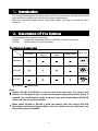
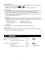
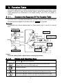
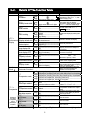
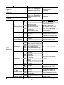
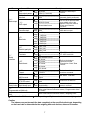
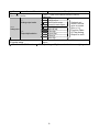
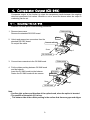
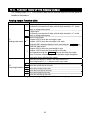
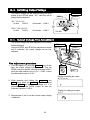
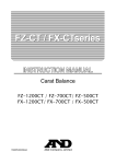
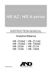
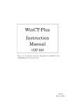
GX-04K
(Comparator output / RS-232C /
Current loop output)
GX-06K
(Analog output / Current loop output)
WM+PD4000853A
This Manual and Marks
All safety messages are identified by the following, “WARNING” or “CAUTION”, of
ANSI Z535.4 (American National Standard Institute: Product Safety Signs and
Labels). The meanings are as follows:
WARNING
CAUTION
A potentially hazardous situation which, if not avoided,
could result in death or serious injury.
A potentially hazardous situation which, if not avoided,
may result in minor or moderate injury.
This is a hazard alert mark.
This manual is subject to change without notice, at any time, to improve the
product.
The contents of the product specifications and this manual are subject to
change without any obligation on the part of the manufacturer.
Under the copyright laws, the software (program) described in this manual is
copyrighted, with all rights reserved.
The software may be installed into one computer and may not be installed into
other computers without the prior written consent of A&D Company. Copying
includes translation into another language, reproduction, conversion, photocopy
and offer or loan to another person.
Microsoft, Windows, Word and Excel are the registered trademarks of the
Microsoft Corporation.
2004
All rights reserved.
No part of this publication may be reproduced, transmitted, transcribed, or
translated into any language in any form by any means without the written
permission of A&D Company Ltd.
Contents
1.
Introduction ......................................................................................................... 2
2.
2-1.
Description Of The Options................................................................................. 2
Accessories ....................................................................................................................3
3-2.
Function Table..................................................................................................... 4
Details Of The Function Table........................................................................................5
4-1.
4-2.
4-3.
4-4.
4-5.
Comparator Output (GX-04K) ............................................................................. 9
Installing The GX-04K ....................................................................................................9
Comparator (GX-04K) Specifications ......................................................................... 10
Using The Comparator Output.....................................................................................11
Setting The Upper And Lower Limit Values................................................................ 12
Example Of Use .......................................................................................................... 15
5-1.
5-2.
5-3.
5-4.
5-5.
5-6.
5-7.
5-8.
5-9.
5-10.
5-11.
5-12.
Serial Output ..................................................................................................... 16
RS-232C (GX-04K) Specifications.............................................................................. 16
Current Loop Output (GX-04K/GX-06K) Specifications............................................. 18
Connection Of The AD-8121B Printer ........................................................................ 19
Description Of The Item “Data output mode” ............................................................. 20
Description Of The Item “Data format”........................................................................ 21
Description Of The Data Format Added To the Weighing Data............................................ 23
Data Format Examples ............................................................................................... 24
Connection To A Computer And The Use Of WinCT ................................................. 26
Commands .................................................................................................................. 27
Acknowledge Code And Error Codes......................................................................... 28
Control Using CTS And RTS....................................................................................... 29
Settings Related To RS-232C..................................................................................... 29
6-1.
6-2.
6-3.
6-4.
6-5.
6-6.
Analog Output (GX-06K)................................................................................... 30
Installing The GX-06K ................................................................................................. 30
Analog Output (GX-06K) Specifications ..................................................................... 31
Function Table Of The Analog Output ........................................................................ 32
Switching Output Voltage ............................................................................................ 34
Output Voltage Fine Adjustment ................................................................................. 34
Fixed Output Voltage................................................................................................... 35
3.
4.
5.
6.
Instruction manual
1
GX-K series, GF-K series
1. Introduction
This manual describes how the GX-K series and GF-K series options, GX-04K and GX-06K
work, and how to get the most out of them in terms of performance.
Read this manual thoroughly before using either option and keep it at hand for future
reference.
2. Description Of The Options
The description of the options is as follows:
GX-04K
Comparator output with a buzzer / RS-232C / Current loop output
GX-06K
Analog output / Current loop output
Functions and panel view
RS-232C
Function
Current loop
Comparator
output
output
Analog output
Panel view
Standard
GX-04K
GX-06K
:Available,
:Not available
Notes
Options GX-04K and GX-06K can not be used at the same time. The current loop
interface is of the passive type, and an external power supply that provides 20 mA, is
required. The external power supply is not necessary when connecting an AD-8121B
printer with this current loop interface.
When option GX-04K or GX-06K is used, the balance does not comply with IP65
(Dust-tight and Protected Against Water Jets). So, handle the scale with much care
when either option is installed.
2
Comparator output
Contact-outputs, output the comparison results between the weighing data and
upper/lower limit values, using HI , OK , and LO .
Whether or not to sound a buzzer, depending on the results, can be selected.
Analog output
Two modes are available: To convert the specified weight value digits to voltage, and to
convert the weight value, in the range from zero to the weighing capacity, to voltage.
Output voltage range selection: Using the slide switch (0V~/0.2V~) located on the option
panel, the output voltage range can be switched between 0 V to 1 V and 0.2 V to 1V. The
default setting at shipment is 0 V to 1 V.
RS-232C
The RS-232C interface is used to communicate with a printer or a personal computer. Using
the RS-232C interface, the following operations are available through a command from the
computer:
Outputs the weighing data.
Enter balance settings.
Controls the balance.
Reads the balance settings.
Current loop
Current loop is a data output interface, mainly used as a printer interface.
GLP output
GLP-compliant data output is available for RS-232C and current loop. Refer to the balance
instruction manual for details about GLP output.
2-1. Accessories
Each option is provided with the following accessories.
GX-04K:
GX-06K:
DIN connector (plug)
1 piece ...........
Instruction manual (this document)
1 copy
DIN connector (plug)
Screwdriver
1 piece ...........
1 piece ...........
Instruction manual (this document)
1 copy
3
3. Function Table
The function table reads or rewrites the parameters that are stored in the balance. When
GX-04K or GX-06K is used, set the function table to specify the balance performance.
These parameters are maintained in non-volatile memory, even if the AC adapter is
removed.
3-1-1.
Structure And Sequence Of The Function Table
This function table menu consists of two layers. The first layer is the "Class" and the second
layer is the "Item". It has effect that a parameter is stored in each item and is displayed latest.
New parameters are applied to the balance after the PRINT key is pressed.
Example
This example sets "Stores weighing data" for "Data memory" and "1 minute" for "Interval
time".
Weighing mode
Start.
Item
"Data memory"
Press and hold
Press several
times
Press two times
Press several
times
Class
Item
Press five times
Parameter
"Stores weighing data"
Parameter
"1 minute"
Item
"Interval time"
Finish
Weighing mode
Caution
Check the settings and condition before changing parameters.
3-1-2.
Display And Operation Keys
The symbol "〇" shows effective parameter.
When pressed and held in the weighing mode, enters the function table mode.
Selects the class or item in the function table mode.
Changes the parameter.
When a class is displayed, moves to an item in the class.
When an item is displayed, stores the new parameter and displays the next class.
When an item is displayed, cancels the new parameter and displays the next class.
When a class is displayed, exits the function table mode and returns to the weighing mode.
4
3-2.
Class
Details Of The Function Table
Item and Parameter
Cond
Condition
5t-b
Stability band width
Hold
Hold function
trc
Zero tracking
ba5fnc
5pd
Environment Display refresh rate
Display
pnt
Decimal point
p-on
Auto display-ON
poff
Auto display-OFF
g5i
Capacity indicator
add
Accumulation function
rng
Display at start
Cl adj
Clock
Cp fnc
Comparator
Displayed
only when
Comparator
output
(GX-04K) is
installed
0
1
2
0
1
2
0
1
0
1
2
3
0
1
0
1
0
1
0
1
0
1
0
1
0
1
Description
Fast response, sensitive value FAST Can be changed by response
MID. adjustment. With "Hold 1", sets
Slow response, stable value SLOW the averaging time.
The stabilization indicator
Stable when within ±1 digit
illuminates with the display
fluctuation within the range. With
Stable when within ±3 digits
"Hold 1", sets the stable range.
Holds the display when stable in
OFF
animal mode. With "Hold 1",
ON
ANIMAL turns on.
OFF
Normal
Strong
Very strong
5 times/second
10 times/second
Point (.)
Comma (,)
OFF
ON
OFF
ON (10 minutes)
OFF
ON
OFF
ON
Displays
Does not display
Keeps zero display by tracking zero
drift.
Period to refresh the display
Decimal point format
Turns on the weighing mode
display when the AC adapter is
connected.
Turns off the display after 10
minutes of inactivity.
Capacity indicator.
Zero:
0%
Maximum capacity: 100%
Displays and outputs the total
value of the weighing data.
Select whether or not to display
the smallest displayable weighing
value at weighing start.
Confirms and sets the time and
date. The time and date are
added to the output data.
Refer to the balance instruction manual, " Clock and
Calendar Function".
0 No comparison
1 Comparison, excluding "near zero" when stable value or overloaded
Cp
2 Comparison, including "near zero" when stable value or overloaded
Comparator mode
3 Continuous comparison, excluding "near zero"
4 Continuous comparison, including "near zero"
Select Cp Hi or Cp lo.
0 Sets the upper / lower limit
Cp in
value
Data input method
Select Cp ref or Cp lmt.
1 Sets the reference value
Select whether or not to add the
0
Not
added
Cp-r
comparison results to the output
Comparison results
1 Added
data.
Displays the results on the main
0
OFF
Cp-b
portion of the display in place of
Main display comparison
1 ON
the weight value.
0 OFF
bep
Select whether or not to sound
the LO buzzer.
LO buzzer
1 ON
0 OFF
bep
Select whether or not to sound
the OK buzzer.
OK buzzer
1 ON
0 OFF
bep
Select whether or not to sound
the HI buzzer.
HI buzzer
1 ON
: Functions for GX-K series.
: Factory settings. Digit is a unit of minimum weighing value.
5
Class
Item and Parameter
Cp Hi
Upper limit
Cp lo
Lower limit
Cp ref
Reference value
Cp lmt
Tolerance
Description
Refer to "4-4. Setting The
Upper And Lower Limit
Values"
Displayed when Cp in 0
is selected.
Refer to "4-4. Setting The
Upper And Lower Limit
Values"
Displayed when Cp in 1
is selected.
0 Key mode
Auto print mode A
prt
Data output mode
1 (Reference = zero)
2
3
ap-p
Auto print polarity
ap-b
Auto print difference
dout
Data output
data
Data memory
int
Interval time
d-no
Data number output
5-td
Time/Date output
5-id
ID number output
: Functions for GX-K series.
Auto print mode B
(Reference = last stable
value)
Stream mode /
Interval memory mode
Accepts the PRINT key only
when the display is stable.
Outputs data when the
display is stable and
conditions of ap-p, ap-b and
the reference value are met.
With data 0, outputs data
continuously; with data 2, uses
interval memory.
Displayed value > Reference
Displayed value < Reference
Regardless of displayed value
0 Plus only
1 Minus only
2 Both
0 10 digits
Difference between reference
1 100 digits
value and displayed value
2 1000 digits
0 Not used
1 Stores unit mass in counting mode
2 Stores weighing data
Related items:
prt
, int, d-no, 5-td, info
Stores
calibration
data
3
4 Stores comparator settings
5 Stores tare value
0 Every measurement
1 2 seconds
2 5 seconds
3 10 seconds
Interval time in the interval
memory mode when using prt
4 30 seconds
3, data 2
5 1 minute
6 2 minute
7 5 minute
8 10 minute
Refer to the balance
0 No output
instruction manual, "DATA
1 Output
MEMORY"
0 No output
Selects whether or not the
time or date is added to the
Time
only
1
weighing data. Refer to the
2 Date only
balance instruction manual, "
Clock and Calendar Function".
3 Time and date
0 No output
Selects whether or not the ID
number is output.
1 Output
: Factory settings. Digit is a unit of minimum weighing value.
6
Class
dout
Data output
Item and Parameter
pU5e
Data output pause
at-f
Auto feed
info
GLP output
ar-d
Zero after output
bp5
Baud rate
btpr
Data bit, parity bit
5if
Serial
interface
Crlf
Terminator
type
Data format
t-Up
Timeout
erCd
AK, Error code
Ct5
CTS, RTS control
d5 fnc
ldin
Density function Liquid density input
mlt
Programmable-unit (Multi-unit)
Unit
Unit
: Functions for GX-K series.
Description
0
1
0
1
0
1
No pause
Pause (1.6 seconds)
Not used
Used
No output
AD-8121 format
2 General data format
0
1
0
1
2
3
4
5
0
1
2
0
1
0
1
2
3
4
5
0
1
0
1
0
1
0
1
Selects the data output
interval.
Selects whether or not
automatic feed is performed.
Selects GLP output method.
For how to set time and date
to be added, refer to the
balance instruction manual,
"Clock and Calendar
Function".
Adjusts zero automatically
after data is output
Not used
Used
600 bps
1200 bps
2400 bps
4800 bps
9600 bps
19200 bps
7 bits, even
7 bits, odd
8 bits, none
CR LF
CR: ASCII code 0Dh
LF: ASCII code 0Ah
CR
A&D standard format
DP format
Refer to the balance
KF format
instruction manual,
"Description of Item "Data
MT format
Format".
NU format
CSV format
No limit
Selects the wait time to
receive a command.
1 second
No output
AK: ASCII code 06h
Output
Not used
Controls CTS and RTS.
Used
Water temperature
Available only when density
mode is selected
Liquid density
Available only when programmable-unit mode is selected.
Refer to the balance instruction manual, "Programmable Units"
for details".
Refer to the balance instruction manual, "Weighing Units".
: Factory settings. Digit is a unit of minimum weighing value.
Caution
The balance may not transmit the data completely at the specified refresh rate, depending
on the baud rate or data added to the weighing data such as time, date and ID number.
7
Class
Item and Parameter
Description
Displayed
only
when
the
internal
mass value correction switch
C5 in
is set to 1. Refer to the balance instruction manual,
Internal mass correction
"Calibration".
0 2-digit output
an
1 3-digit output
Displayed only
Analog output mode
2 Net full scale output
when the GX-06K
3 Gross full scale output
option is installed.
aout
0 First digit
Refer to "6-3.
Analog output
1 Second digit
Function Table
5el
2 Third digit
Of The Analog
Output digit selection
3 Fourth digit
Output" for detail.
4 Fifth digit
5 Sixth digit
id
Refer to the balance instruction manual, "ID Number And GLP
Report".
ID number setting
: Functions for GX-K series.
: Factory settings. Digit is a unit of minimum weighing value.
8
4. Comparator Output (GX-04K)
Comparator output, is the function to output the comparison results between the weighing
data and upper/lower limit values. Whether or not to sound the buzzer when the output is
conducting can be set.
4-1. Installing The GX-04K
Install the GX-04K option in the following procedures:
1. Remove two screws.
Remove the standard RS-232C board.
Rubber packing
Cable
2. Unlock and remove two connectors from the
standard RS-232C board.
Connector with lock
Do not pull the cable.
Screw
Step 2
Step 1
RS-232C Board
3. Connect two connectors to the GX-04K board.
Rubber packing
4. Put the rubber packing between GX-04K board
and the balance.
Insert the GX-04K board into the balance.
Fasten the GX-04K board with two screws.
Cable
Connector
Switch (S1)
Screw
Step 3
Step 4
GX-04K board
Note
Confirm right surface and direction of the option board, when the option is inserted.
The position of the switch (S1) is free.
The balance side of the rubber packing is the surface that there are gaps and ridges.
9
4-2. Comparator (GX-04K) Specifications
Maximum contact voltage:
Maximum contact current:
Maximum contact resistance:
100 VDC
100 mA DC
20 Ω
Comparator output judgement conditions (when upper limit value ≥ lower limit value):
Weighing data > upper limit value: .................................. Activates the HI comparator output.
Upper limit value 7 weighing data 7 lower limit value: ... Activates the OK comparator output.
Weighing data < lower limit value: .................................. Activates the LO comparator output.
Reference value setting:
Contact output:
Buzzer:
Input the upper and lower limit values digitally or using a sample.
Select whether or not to and how to compare, using "Cp
comparator mode" of the balance function table.
Select whether or not to sound the buzzer, using "bep buzzer
mode" of the balance function table.
Panel View
Circuit
HI
OK
HI
OK
LO
LO
Pin Assignments
COM
Pin No.
Description
1
HI
(Comparator)
2
COM
(Comparator)
3
Sending loop (Current loop)
4
LO
(Comparator)
5
Sending loop (Current loop)
6
OK
(Comparator)
7
No connection
Housing Shield
For details on pins 3 and 5 of current loop, Refer to “5-2.Current Loop Output (GX-04K/GX-06K)
Specifications”.
10
4-3. Using The Comparator Output
To use the comparator output, perform the following four steps.
1. Connect the peripheral equipment to the option’s 7-pin DIN connector.
2. Set the “Comparator (Cp fnc)” parameter of the balance function table. For details, Refer to
“3. Function Table”.
3. Set the upper and lower limit values. For details, refer to “4-4. Setting The Upper And
Lower Limit Values”.
Weighing data
Conducting
4. When performing a weighing, the
(Short)
comparison result is output. When the
Upper limit
Conducting
weighing data is equal to or less than
(Short)
Lower limit
the upper limit value, and equal to or
Conducting
greater than the lower limit value, the
(Short)
OK comparator will be output.
LO
OK
HI
Comparator output
LO
Weighing data > upper limit
Open
Upper limit 7 weighing data 7 lower limit
Conducting
(Short)
Weighing data < lower limit
OK
Conducting
(Short)
HI
Conducting
(Short)
Open
Whether or not to sound the buzzer, when the contact output is conducting can be set in the
“Buzzer mode (bep) of the “Comparator (Cp fnc)”.
Note
Make sure that the upper limit value is greater than the lower limit value.
Comparator output
Class
Cp fnc
Comparator
Item and Parameter
Cp
Comparator mode
Cp in
Data input method
Cp-r
Comparison results
Displayed
only when
Comparator
output
(GX-04K) is
installed
Cp-b
Main display comparison
bep
LO buzzer
bep
OK buzzer
bep
HI buzzer
Description
0
1
2
3
4
0
1
0
1
0
1
0
1
0
1
0
1
No comparison
Comparison, excluding "near zero" when stable value or overloaded
Comparison, including "near zero" when stable value or overloaded
Continuous comparison, excluding "near zero"
Continuous comparison, including "near zero"
Sets the upper / lower limit
Select Cp Hi or Cp lo.
value
Select Cp ref or Cp lmt.
Sets the reference value
Select whether or not to add the
Not added
comparison results to the output
Added
data.
Displays the results on the main
OFF
portion of the display in place of
ON
the weight value.
OFF
Select whether or not to sound
the LO buzzer.
ON
OFF
Select whether or not to sound
the OK buzzer.
ON
OFF
Select whether or not to sound
the HI buzzer.
ON
11
Class
Item and Parameter
Cp Hi
Upper limit
Cp lo
Lower limit
Cp ref
Reference value
Cp lmt
Tolerance
Description
Refer to "4-4. Setting The
Upper And Lower Limit
Values"
Displayed when Cp in 0
is selected.
Refer to "4-4. Setting The
Upper And Lower Limit
Values"
Displayed when Cp in 1
is selected.
: Factory settings.
4-4. Setting The Upper And Lower Limit Values
The results of the comparison are indicated by HI, OK or LO on the display.
Operating conditions:
No comparison
Comparison when the weighing data is stable or overloaded,
excluding “near zero”
Comparison when the weighing data is stable or overloaded,
including “near zero”
Continuous comparison, excluding “near zero”
Continuous comparison, including “near zero”
To compare, use:
Upper limit value and lower limit value
Reference value and tolerance value
Input method:
Digital input
Weighing input
"near zero" means that weighing value is within ±10 digits from zero point.
Example: In case of GX-20K, the range of ±1.0g is "near zero".
4-4-1.
Example 1
Comparison when the weighing data is stable or overloaded, excluding "near zero", upper
limit and lower limit.
Selecting a comparator mode
Step 1 Press and hold the SAMPLE key until ba5fnc of the function table is displayed,
then release the key.
Step 2 Press the SAMPLE key several times to display Cp fnc .
Step 3 Press the PRINT key.
Step 4 Press the RE-ZERO key several times to display Cp 1 .
Step 5 Press the SAMPLE key to display Cp in .
Step 6 Press the RE-ZERO key several times to display Cp in 0 .
Step 7 Press the PRINT key to store the selected mode.
12
Entering the upper and lower limit values
Step 8 With Cp Hi displayed, press the PRINT key. The current setting of the upper
limit value is displayed with all of the digits blinking.
When the current setting is not to be changed, press the PRINT or CAL key to
go to step 9.
When the current setting is to be changed, press the RE-ZERO key.
The balance is now in the digital input mode. To use the weighing input mode,
press and hold the MODE key.
Digital input mode
Change the setting using the following keys.
SAMPLE key..... To select the digit to change the value.
RE-ZERO key ... To change the value of the digit selected.
MODE key........ To switch the polarity.
PRINT key ........ To store the new setting and go to step 9.
CAL key ........... To cancel the new setting and go to step 9.
Weighing input mode
Press the RE-ZERO key. The balance displays 0.0 g . Place a sample, with a mass
that corresponds to the upper limit value, on the pan. Press the PRINT key to
store the upper limit value. Remove the sample. The balance displays Cp lo .
Step 9 With Cp lo displayed, press the PRINT key. The current setting of the lower limit
value is displayed with all of the digits blinking.
When the current setting is not to be changed, press the PRINT or CAL key to go
to step 10.
When the current setting is to be changed, press the RE-ZERO key.
The balance is now in the digital input mode. To use the weighing input mode, press
and hold the MODE key.
Enter the lower limit value in the same way as described in step 8. Then, go to step
10.
Step 10 Press the CAL key to exit the comparator function and return to the weighing mode.
4-4-2.
Example 2
Continuous comparison, including "near zero", reference value and tolerance value.
Selecting a comparator mode
Step 1 Press and hold the SAMPLE key until ba5fnc of the function table is displayed,
then release the key.
Step 2 Press the SAMPLE key several times to display Cp fnc .
Step 3 Press the PRINT key.
Step 4 Press the RE-ZERO key several times to display Cp 4 .
Step 5 Press the SAMPLE key to display Cp in .
Step 6 Press the RE-ZERO key several times to display Cp in 1 .
Step 7 Press the PRINT key to store the selected mode.
13
Entering the reference and tolerance values
Step 8 With Cp ref displayed, press the PRINT key. The current setting of the reference
value is displayed with all the digits blinking.
When the current setting is not to be changed, press the PRINT or CAL key to go
to step 9.
When the current setting is to be changed, press the RE-ZERO key.
The balance is now in the digital input mode. To use the weighing input mode, press
and hold the MODE key.
Digital input mode
Change the setting using the following keys.
SAMPLE key ..... To select the digit to change the value.
RE-ZERO key .... To change the value of the digit selected.
MODE key ........ To switch the polarity.
PRINT key ........ To store the new setting and go to step 9.
CAL key ........... To cancel the new setting and go to step 9.
Weighing input mode
Press the RE-ZERO key. The balance displays 0.0 g . Place a sample , with a
mass that corresponds to the reference value, on the pan. Press the PRINT key
to store the reference value. Remove the sample. The balance displays Cp lmt .
Step 9 With Cp lmt displayed, press the PRINT key. The current setting of the tolerance
value is displayed with all the digits blinking.
When the current setting is not to be changed, press the PRINT or CAL key to go
to step 10.
When the current setting is to be changed, press the RE-ZERO key.
The balance is now in the digital input mode. Change the setting using the following keys.
SAMPLE key ..... To select the digit to change the value.
RE-ZERO key .... To change the value of the digit selected.
PRINT key ........ To store the new setting and go to step 10.
CAL key ........... To cancel the new setting and go to step 10.
Note Enter the tolerance value in percentage, with the reference value as 100%.
Only the digital input mode is available for setting the tolerance value.
The MODE key is not used to set the tolerance value.
Step 10 Press the CAL key to exit the comparator function and return to the weighing mode.
Note When Pound/Ounce is selected as a weighing unit, enter the values in ounces
for comparison.
In the density mode, comparison is performed to the density obtained.
14
4-5. Example Of Use
The following example uses the AD-8951 comparator light, which is sold separately, to
display the comparison result in red, green, or orange.
1
Using the AX-KO507-W200 cable, which is sold separately, connect the comparator light to
the balance as shown below.
2. Set the “Comparator (Cp fnc)” of the balance function table as follows:
Cp 3
Compares the result excluding the data near zero continuously.
Cpin 0
Inputs the upper or lower limit values.
bep 1
Sounds the buzzer for LO.
Red
bep 0
Does not sound the buzzer for OK.
GX-04K
Green
bep 1
Sounds the buzzer for HI.
Orange
3. Set the upper and lower limit values as follows:
Cp Hi
1010.0 g (Upper limit)
Cp lo
990.0 g (Lower limit)
HI
OK
LO
4. Functions of the comparator and buzzer are as
follows, depending upon the comparison result.
Weighing data
900.0 g
1000.0 g
1100.0 g
Comparator light
Buzzer
Orange
Sounds
Green
Does not sound
Red
Sounds
15
Comparator light
AD-8951
AX-KO507-W200
5. Serial Output
5-1. RS-232C (GX-04K) Specifications
D-Sub 25 pin numbers
M2.6
ISO metric screw thread
D-Sub 25 pin assignments
Pin No.
1
2
3
4
5
6
Signal name
FG
RXD
TXD
RTS
CTS
DSR
7
SG
18
19
Others
PRINT
RE-ZERO
-
Interface type
RS-232C
RS-232C
RS-232C
RS-232C
RS-232C
RS-232C / external contact
input
External contact input
External contact input
-
RS-232C
Direction
Input
Output
Input
Output
Output
Input
Input
-
Description
Frame ground
Receive data
Transmit data
Ready to send
Clear to send
Data set ready
Signal ground
Same as the PRINT key
Same as the RE-ZERO key
No connection
The balance is a DCE device. Connect the balance to a personal computer (DTE) using a
straight through cable.
Transmission system : EIA RS-232C
Transmission form
: Asynchronous, bi-directional, half duplex
Transmission rate
: 10 times/second or 5 times/second (same as data refresh rate)
Data format
: Baud rate : 600, 1200, 2400, 4800, 9600, 19200 bps
Data bits : 7 or 8 bits
Parity
: Even, Odd (Data bits 7 bits)
None
(Data bits 8 bits)
Stop bit : 1 bit
(When sending, 2 bits; receiving, 1 bit.
A personal computer will function with either setting.)
Code
: ASCII
One character format
RS-232C
-5V to -15V
+5V to +15V
Data bits
Stop bit
Start bit
Parity bit
16
RS-232C Terminals
Balance side
DCE
Computer side
DTE
Inside of balance
Terminals sample
External contact input
By connecting pin 18 (PRINT command) to
pin 7, or pin 19 (RE-ZERO command) to pin
7 for 100 ms or more, the same operation as
performed by pressing the PRINT key or
the RE-ZERO key, will be performed.
Accessory
Connector :
Foot switch :
Example of foot switch
Connector
AX-HDB-25P
Connector cover
AX-HDB-CTF
Foot switch
AX-SW128
AX-HDB-25P/CTF
AX-SW128
Balance
side
PRINT key
RE-ZERO key
17
5-2. Current Loop Output (GX-04K/GX-06K) Specifications
The specifications of the current loop interface are as follows:
Transmission system : 20 mA current loop (Passive)
Transmission form
: Asynchronous, uni-directional (Only from the balance)
Data format
: Baud rate : 600, 1200, 2400, 4800, 9600, 19200 bps
Data bits : 7 or 8 bits
Parity
: Even, Odd (Data bits 7 bits)
None
(Data bits 8 bits)
Stop bit : 1 bit
Code
: ASCII
One character format
20mA
0mA
Data bits
Start bit
Stop bit
Parity bit
Notes
To use current loop, an external power supply that
provides 20 mA, is required.
The maximum rated voltage of the current loop is 25 V.
When a baud rate of 4800 bps or higher is used,
communication may not be performed properly.
Circuit
Sending loop
(Current loop)
3 pin
5 pin
Sending loop
(Current loop)
Current loop output
Pin assignments
GX-04K
Pin No.
1
2
3
4
5
6
7
Housing
Shield
Description
HI
(comparator)
COM
(comparator)
Sending loop (Current loop)
LO
(comparator)
Sending loop (Current loop)
OK
(comparator)
No connection
Shield
GX-06K
Pin No.
1
2
3
4
5
6
7
Housing
Description
No connection
Analog GND (Analog output)
Sending loop (Current loop)
No connection
Sending loop (Current loop)
No connection
Analog output (Analog output)
Shield
For details on the comparator of GX-04K, Refer to “4-2. Comparator (GX-04K) Specifications”.
For details on the analog output of GX-06K, Refer to “6-2. Analog Output (GX-06K) Specifications”.
18
5-3. Connection Of The AD-8121B Printer
Preset the following parameters to use the AD-8121B printer.
Factory AD-8121B
Class
Item and Parameter settings
MODE 1
dout
Data output
5if
Serial
interface
prt
Data output mode
ap-p
Auto print polarity
ap-b
Auto print difference
d-no
Data number output
5-td
Time/Date output
5-id
ID number output
pU5e
Data output pause
at-f
Auto feed
bp5
Baud rate
btpr
Data bit, parity bit
Crlf
Terminator
type
Data format
Ct5
CTS, RTS control
AD-8121B
MODE 2
AD-8121B
MODE 3
0,1,2
3
0,1,2
#1
Not
necessary
#1
0
0
0
0,1
0
0
0
0,1,2,3
0
0
0
0,1
0
0
0
0
0
0
0,1
2
2
2
2
0
0
0
0
0
0
0
0
0
0
0
1
0
0
0
0
0
0
1
0,1
#2
ON
#1 Set parameters when auto print mode A or B (prt 1 or 2) is selected.
#2 Set 1 when multiple lines are printed. Example: When appending ID number, set 1.
Settings of AD-8121B
AD-8121B
MODE
Description
DIP switch
MODE
Print at receiving data.
MODE 1
Standard mode, statistic mode
ON
Print by DATA key operation or built-in timer.
Standard mode, interval mode, chart mode
ON
1 2 3 4
MODE
1 2 3 4
MODE 2
Print at receiving data.
Dump print mode
MODE
1 2 3 4
MODE 3
1 2 3 4
ON
19
ON
DIP switch No.3 : Handling unstable
data
DIP switch No.4 : Data input specifications
MODE
MODE
ON
Print
ON
Current loop
OFF Not printed
OFF
RS-232C
Refer to print samples of "GLP Report" in the instruction manual of GX-K/GF-K series.
GF-K series does not output the time and date. Use the calendar function of the AD-8121B.
GF-K series does not store the calibration report in memory.
AD-8121B Printer
Compact dot-matrix printer
Statistical function, clock and calendar function, interval print
function, graphic print function, dump print mode
5 x 7 dots, 16 characters per line
Print paper (AX-PP143, 45 (W) x 50 (L) mm , ø65 mm)
AC adapter or alkaline battery
1 2 3 4
5-4. Description Of The Item “Data output mode”
The parameter setting of "Data output mode (prt)" applies to the performance when the
"Data memory (data)" parameter is set to "2" (to store the weighing data) and when the data
is transmitted using the RS-232C interface.
Key mode
When the PRINT key is pressed with the stabilization indictor turned on, the balance
outputs or stores the weighing data and the display blinks one time.
Required setting
dout
prt 0
Key mode
Auto print modes A and B
When the displayed value is stable and the conditions of "Auto print polarity", "Auto print
difference" and reference value are met, the balance outputs or stores the weighing data.
When the PRINT key is pressed with the stabilization indictor turned on, the balance
outputs or stores the data and the display blinks one time.
Auto print modes A
Example
For weighing each time a sample is placed and removed, with "ar-d"
set to "1" (to adjust zero after the data is output).
Required setting
dout
prt 1
Auto print mode A (reference = zero)
dout
ap-p
Auto print polarity
dout
ap-b
Auto print difference
dout
ar-d 1 Zero after output
Auto print modes B
Example
For weighing while a sample is added.
Required setting
dout
prt 2
Auto print mode B (reference = last stable value)
dout
ap-p
Auto print polarity
dout
ap-b
Auto print difference
Stream mode
The balance outputs the weighing data continuously regardless of the display condition. The
display does not blink in this mode. The interval memory mode is used when the "Data
memory (data)" parameter is set to "2" (to store the weighing data).
Example
For monitoring data on a computer.
Required setting
dout
prt 3
Stream mode
dout
data 0 Data memory function is not used
ba5fnc 5pd
Display refresh rate
5if
bp5
Baud rate
Caution The balance may not transmit the data completely at the specified refresh rate,
depending on the baud rate or data added to the weighing data such as time,
date and ID number.
20
Interval memory mode
The weighing data is periodically stored in memory.
Example
For periodical weighing without a personal computer command and
to output all of the data, to a computer, at one time.
The GX-K series can use time and date with "Time/Date output (5-td)".
Required setting
dout
prt 3
Interval memory mode
dout
data 2 Data memory function is used
dout
int
Interval time
Optional setting
dout
5-td1, 2, or 3
Adds the time and date.
5-5. Description Of The Item “Data format”
A&D standard format
5if type 0
This format is used when the peripheral equipment can receive the A&D format.
If an AD-8121B is used, set the printer to MODE 1 or 2.
This format consists of fifteen characters excluding the terminator.
A header of two characters indicates the balance condition.
The polarity sign is placed before the data with the leading zeros. If the data is zero, the plus
sign is applied.
The unit, consisting of three characters, follows the data.
Header
Data
Stable header
Unstable header
Overload header
Unit
Terminator
Stable header of counting mode
DP (Dump print) format 5if type 1
This format is used when the peripheral equipment can not receive the A&D format.
If an AD-8121B is used, set the printer to MODE 3.
This format consists of sixteen characters excluding the terminator.
A header of two characters indicates the balance condition. No overload header is used.
The polarity sign is placed before the data, with spaces in place of leading zeros, if the data
is not zero or overloaded.
The unit, consisting of three characters, follows the data.
Header
Data
Stable header
Unstable header
Unit
Terminator
Stable header of counting mode
21
KF format
5if type 2
This is the Karl-Fischer moisture meter format and is used when the peripheral equipment
can only communicate using this format.
This format consists of fourteen characters excluding the terminator.
This format has no header characters.
The polarity sign is placed before the data, with spaces in place of leading zeros, if the data
is not zero or overloaded.
This format outputs the unit only for a stable value.
Data
Unit
Terminator
Stable value
Unstable value
MT format
5if type 3
A header of two characters indicates the balance condition.
The polarity sign is used only for negative data.
The weighing data uses spaces in place of the leading zeros.
The character length of this format changes dependent upon the unit
Header
Data
Unit
Terminator
Stable header
Unstable header
Overload header
NU (numerical) format
5if type 4
This format outputs only numerical data.
This format consists of nine characters excluding the terminator.
The polarity sign is placed before the data with the leading zeros. If the data is zero, the plus
sign is used.
Data
Terminator
CSV format
5if type 5
This format separates the data of A&D standard format and the unit by a comma ( , ).
This format outputs the unit even when the data is overloaded.
When the ID number, data number, time and date are added at "Data output (dout)" of the
function table, outputs ID number, data number, date, time and weighing data in this order
and separates each item by a comma and treats all the items as one group of data.
Note
GF-K series can not add the format of time and date.
ID number Data number
Date
Time
Weighing data
22
5-6. Description Of The Data Format Added To the Weighing Data
ID number
dout 5-id 1
Data number
dout d-no 1
The number to identify a specific balance.
This format consists of seven characters excluding the terminator.
This format outputs the data number just before the data is transmitted using the RS-232C
interface.
This format consists of six characters excluding the terminator.
When CSV format (5if type 5) is selected, the period ( . ) is replaced with a comma ( , ).
Data number
Terminator
Date
dout 5-td 2 or 3
The date output order can be changed in "Clock (Cl adj)".
The year is output in a four-digit format.
Note
GF-K series does not use this format.
Time
dout 5-td 1 or 3
This format outputs time in 24-hour format.
Note
GF-K series does not use this format.
Tare value
When the tare value in memory is recalled, the tare value is output before the weighing data.
Tare value recalled from memory
Net value
Comparison results
By setting "Comparison results (Cp-r)" of the function table to "1", the comparison results
can be added to the data output using the RS-232C serial interface. Use A&D standard
format (type 0). The comparison results are added after the header in A&D standard format
as below.
Header
Data
Unit
Comparison result
When the comparison result is HI
When the comparison result is OK
When the comparison result is LO
Not applicable
Terminator
Note
When the data described above is added to the weighing data, the output is in the
following order: ID number, Data number, Date, Time and Weighing data.
23
5-7. Data Format Examples
Stable
Unstable
Overload
Positive error
Overload
Negative error
Space, ASCII 20h
Carriage Return, ASCII 0Dh
Line Feed, ASCII 0Ah
24
Units
A&D
D.P.
KF
g
kg
Counting mode
Precent mode
Ounce (Avoir)
Pound
Pound Ounce
Troy Ounce
Metric Carat
Momme
Pennyweight
Grain
Tael (HK general, Singapore)
Tael (HK, jewelry)
Tael (Taiwan)
Tael (China)
Tola (India)
Messghal
Density
Multi
Space, ASCII 20h
Note
When "Pound Ounce" is selected, the data is output with the unit of ounce (oz).
The unit Grain is not available for the GX-32K and GF-32K.
25
MT
5-8. Connection To A Computer And The Use Of WinCT
The balance is of the DCE type (Data Communication Equipment), which can be connected
to a personal computer using the RS-232C interface. Before connection, read the personal
computer manual thoroughly. Use a standard DCE cable for connection (cable type:
straight-through). When the personal computer type is a DOS/V with a 9-pin port, use a
straight-through cable with a 25-pin male connector and a 9-pin female connector.
Using Windows Communication Tools Software (WinCT)
When Windows is used as an operating system in a personal computer, the provided
WinCT software can be used to transmit the weighing data to the personal computer.
The WinCT software has two communication methods: "RsCom" and "RsKey". Refer to the
WinCT instruction manual.
RsCom
RsCom can transmit commands to control the balance.
RsCom can make bi-directional communication between the balance and a personal
computer using the RS-232C interface.
RsCom can display or store the data using a text file format. RsCom can also print the data
using a printer connected to the personal computer.
When several ports of a personal computer have balances connected, can communicate
with each balance simultaneously.
RsCom can share a personal computer with other application software.
RsCom can receive the balance GLP report.
RsKey
RsKey can transmit the weighing data output from the balance directly to other application
software such as Microsoft Excel.
RsKey can be used with most application software.
RsKey can receive the balance GLP report.
Using the WinCT software, the balance can do the following:
Analyzing the weighing data and the statistics with "RsKey"
The weighing data can be input directly into an Excel worksheet. Then, Excel can analyze
the data to obtain total, average, standard deviation, maximum and minimum value, and
display them in a graph.
Controlling the balance using commands from a personal computer
By using "RsCom", the personal computer sends commands such as "re-zero" or "send
weighing data" to the balance and controls the balance.
Printing the balance GLP report using your printer
The balance GLP report can be printed using a printer connected to the personal computer.
Receiving weighing data at a certain interval
The weighing data can be received at a certain interval and data characteristic with elapsed
time can be obtained.
Using the balance memory function
The data can be stored in the balance’s memory. Of the data stored, the weighing data and
calibration data can be transmitted to a personal computer at one time.
Using a personal computer as an external indicator
With the "RsKey" test mode function, a personal computer can be used as an external weight
indicator for the balance. (To do this, set the balance data output mode to stream mode.)
26
5-9. Commands
Note A command has a terminator added, that is specified using "5if Crlf" of the
function table, and is sent to the balance.
Commands to query weighing data
C
Cancels the S or SIR command.
Q
Requests the weighing data immediately.
S
Requests the weighing data when stabilized.
SI
Requests the weighing data immediately.
SIR
Requests the weighing data continuously.
Commands to control the balance
Requests the upper/lower limit value code number of the selected value.
?CN
Requests the upper limit value.
?HI
Requests the identification number.
?ID
Requests the lower limit value.
?LO
Outputs all weighing data in memory.
?MA
Outputs data with the data number nnn. nnn: Three digits
?MQnnn
Outputs the number of data in memory (the last data number)
?MX
Request the tare number of the selected value.
?PN
Request the tare value.
?PT
Request the serial number of the balance.
?SN
Request the model name of the balance.
?TN
Requests the unit mass numbers in memory.
?UN
Requests the unit mass value.
?UW
Same as the CAL key.
CAL
Recalls the upper/lower limit value in memory. mm: 01 to 20.
CN:mm
Sets the upper limit values. ~ is space mark.
Example: the upper limit value is 2000.0 g.
HI:∗∗∗∗∗∗.∗~~g
Command: HI:+002000.0~~g
Sets identification number.
ID:∗∗∗∗∗∗∗
Sets the lower limit values. ~ is space mark.
Example: the lower limit value is 1000.0 g.
LO:∗∗∗∗∗∗.∗~~g
Command :LO:+001000.0~~g
Deletes all data in memory.
MCL
Deletes data with the data number nnn. nnn: Three digits.
MD:nnn
Turns the display off.
OFF
Turns the display on.
ON
Same as the ON:OFF key
P
Recalls the tare value in memory. mm: 01 to 20.
PN:mm
Same as the PRINT key
PRT
Sets the tare value. ~ is space mark.
Example: the tare value is 1000.0 g.
PT:∗∗∗∗∗.∗~~g
Command :PT:+001000.0~~g
Same as the RE-ZERO key
R
Same as the SAMPLE key.
SMP
Same as the MODE key
U
27
Commands to control the balance
Recalls the unit mass values in memory. mm: 01 to 50.
UN:mm
Changes the unit mass value. Use "g" of unit. ~ is space mark.
Example: the unit mass value is 2000.0 g.
UW:∗∗∗∗∗∗.∗~~g
Command: UW: +002000.0~~g
When a unit is required in commands such as a "PT:" command, use the 3-digit unit
code of the A&D standard format.
nnn indicates a three-digit numerical value.
5-10. Acknowledge Code And Error Codes
When the "Serial interface function (5if)" parameter is set to "erCd 1", the balance outputs
<AK> code or error code to each command as follows:
<AK> (06h)
Acknowledge in ASCII code.
When the balance receives a command to request data and can not process it, the balance
transmits an error code (EC, Exx).
When the balance receives a command to request data and can process it, the balance
outputs the data.
When the balance receives a command to control the balance and can not process it, the
balance transmits an error code (EC, Exx).
When the balance receives a command to control the balance and can process it, the
balance transmits the acknowledge code.
Among commands to control the balance, the following transmit the acknowledge code
both when the balance receives the command and when the balance has
accomplished the command. If the command can not be processed properly, the
balance transmits an error code (EC, Exx). This error can be released using the CAL
command.
CAL command (Calibration command using internal mass)
ON command (Display ON command)
P command (Display ON/OFF command)
R command (RE-ZERO command)
When a communication error has occurred due to external noise, or a parity error has
occurred due to transmission error, the balance transmits an error code. In this case, send
the command again.
xx is error code number.
28
5-11. Control Using CTS And RTS
Depending on the "Ct5" parameter of "Serial interface (5if)", the balance performs as follows:
Ct5 0
Regardless of whether the balance can receive a command or not, the balance keeps the
CTS line HI. The balance outputs data regardless of the condition of the RTS line.
Ct5 1
The CTS line is kept Hi normally. When the balance can not receive the next command
(Example: while the balance is processing the last command), the balance sets the CTS line
to Lo. The balance confirms the level of the RTS line before outputting a set of data. If the
RTS level is Hi, the balance outputs data. If the RTS level is Lo, data is not output (The data
is canceled).
5-12. Settings Related To RS-232C
Concerning the RS-232C, the balance has two functions: "Data output (dout)" and "Serial
interface (5if)". Set each function as necessary.
29
6. Analog Output (GX-06K)
6-1. Installing The GX-06K
Install the GX-06K option in the following procedures:
1. Remove two screws.
Remove the standard RS-232C board.
Rubber packing
2. Unlock and remove two connectors from the
standard RS-232C board.
Do not pull the cable.
Cable
Connector with lock
Step 2
Screw
Step 1
RS-232C Board
3. Connect two connectors to the GX-06K board.
Rubber packing
4. Put the rubber packing between GX-06K board
and the balance.
Insert the GX-06K board into the balance.
Fasten the GX-06K board with two screws.
Cable
Connector
Switch (S1)
Screw
Step 3
Step 4
GX-06K board
Note
Confirm right surface and direction of the option board, when the option is inserted.
The position of the switch (S1) is free.
The balance side of the rubber packing is the surface that there are gaps and ridges.
30
6-2. Analog Output (GX-06K) Specifications
The specifications of the analog output unit (GX-06K) are as follows:
Output impedance
100 Ω or less
Linearity
±0.3% or less
Output connector
7-pin DIN connector
Pin connections
Output
Pin 7
GND
Pin 2
Output range
0 V to 1 V
(With the slide switch set to "0V~")
0.2 V to 1 V (With the slide switch set to "0.2V~")
Input impedance of the device connected 10 kΩ or greater
Pin Assignments
Pin No.
1
2
3
4
5
6
7
Housing
Description
No connection
Analog GND(0 V) (Analog output)
Sending loop
(Current loop)
No connection
Sending loop
(Current loop)
No connection
Analog output
(Analog output)
Shield
7 pin
Circuit
Panel View
Zero
Span
Slide switch
0V~ / 0.2V~
Housing
Analog output
10 Ω
2 pin
Current loop output specifications
Analog GND(0 V)
For details on the current loop, Refer to “5-2.Current Loop Output (GX-04K/GX-06K) Specifications”.
Transmission system
20 mA current loop (Passive)
Transmission
Asynchronous, uni-directional (Only from the balance)
Data format
Baud rate: 600, 1200, 2400, 4800, 9600 19200 bps
Data:
7 or 8 bits
Parity:
Even, Odd
(Data 7 bits)
None
(Data 8 bits)
Stop bit: 1 bit or 2 bits
Code:
ASCII
One character format
20mA
0mA
Data bits
Stop bit
Start
bit
Parity
bit
Notes
To use the current loop, an external power supply that provides 20 mA is required.
The maximum rated voltage of the current loop is 25 V.
When a baud rate of 4800 bps or higher is used, communication may not be performed properly.
31
6-3. Function Table Of The Analog Output
The “Analog output (aout)” of the function table can be selected when the GX-06K option is
installed in the balance.
Analog output function table
Item and Parameter
an
Analog output mode
5el
Output digit selection
Description
2-digit output
0 Converts the consecutive 2 digits, with the digit selected in 5el as the
least, to voltage and outputs.
3-digit output
1 Converts the consecutive 3 digits, with the digit selected in 5el as the
least, to voltage and outputs.
Net full scale output
Outputs 0.000 V when the net weight is zero.
2
Outputs 1.000 V when the net weight is full scale.
Outputs 0.000 V when the display is set to zero using the RE-ZERO key.
Gross full scale output
Outputs 0.000 V when the gross weight is zero.
Outputs 1.000 V when the gross weight is full scale.
3
Tare operation using the RE-ZERO key will not affect the output.
(Note: If the tare is extremely light, tare operation might change the
zero point, thus it will affect the output.)
0
1
2
3
4
5
Select the least digit to be output in the mode selected in an.
Only available when 0 or 1 is selected as the output mode.
Select the first digit as the least.
Select the second digit as the least.
Select the third digit as the least.
Select the fourth digit as the least.
Select the fifth digit as the least.
Select the sixth digit as the least.
: Factory settings. Digit is a unit of minimum weighing value.
32
Example
When an 0 is set:
5el
5el
5el
5el
5el
5el
Analog output voltage:"0V~" 0 V to 1 V
0.67 V
0.56 V
0.45 V
0.34 V
0.23 V
0.02 V
0
1
2
3
4
5
Notes
The invisible high-order digits are regarded as zero.
The invisible least digit is regarded as zero (when the minimum weighing value is
turned off using the SAMPEL key).
When an 1 is set:
5el
5el
5el
5el
5el
5el
Analog output voltage: "0V~" 0 V to 1 V
0.567 V
0.456 V
0.345 V
0.234 V
0.023 V
0.002 V
0
1
2
3
4
5
When an 2 or an 3 is set:
GX-8K
GX-10K
GX-12K
GX-20K
GX-30K
GX-8K2
GF-10K
GF-12K
GF-20K
GX-32K
Model
GF-8K
GF-8K2
GF-30K
GF-32K
Full scale
8kg
10kg
12kg
20kg
30kg
For example, when the GX-20K displays 2 kg, the output voltage of an 2 is 0.1 V (when the
slide switch is set to "0V~").
1.000V X
2kg
20kg
=0.100V
Note
"Full scale" of the full scale output mode indicates the full scale values shown in the
table above. The output voltage may exceed 1.000 V, depending on the weighing data.
For example, when the GX-20K displays 21 kg, the output voltage is 1.05 V.
1.000V X
21kg
20kg
=1.05V
33
6-4. Switching Output Voltage
The output voltage can be switched using the slide
switch on the GX-06K panel. "0V~" has been set at
factory before shipment.
"0V~" (0V to1 V):
At zero
0.000 V
At full scale 1.000 V
"0.2V~" (0.2 V to1 V):
At zero
0.200 V
At full scale 1.000 V
Slide switch
"0V~"
"0.2V~"
GX-06K
6-5. Output Voltage Fine Adjustment
The output voltage has been adjusted at the factory
before shipment.
Using the ZERO and SPAN fine-adjustment control
and a voltmeter, the output voltage can be fine
adjusted.
SPAN control
ZERO control
7 pin, +
Fine-adjustment procedure
1. Turn the display off, using the ON:OFF key. At this
time, the output voltage will be at zero. Turn the
ZERO control so that the voltmeter indicates 0.000 V
when the slide switch is set to "0V~"; 0.200 V when
the slide switch is set to "0.2V~".
2 pin, Display for setting the output
to 0 V (0.2 V)
2. While pressing and holding the SAMPLE and
PRINT keys, press the ON:OFF key. The balance
displays p5
. At this time, a voltage of 1 V is
generated. Turn the SPAN control so that the
voltmeter indicates 1.000 V.
3. Repeat steps 1 and 2 until the correct output voltage
is obtained.
34
Display for setting the output
to 1 V
6-6. Fixed Output Voltage
The output voltage is fixed under the following conditions:
1. During operations other than weighing
Example: the display-off state, calibration
: 0 V (or 0.2 V)
2. During the zeroing operation / an 3
an 0, an 1 and an 2
: The previous output value is retained.
: 0 V (or 0.2 V when the slide switch set
to"0.2V~")
3. When "-e" (Weighing pan error) is being displayed
: 0 V (or 0.2 V when the slide switch set
to "0.2V~")
4. When "e" (Overload error) is being displayed
: Output voltage is as shown below.
(when the slide switch is set to "0V~")
GX-8K
GX-10K
GX-12K
GX-20K
GX-30K
Model
GX-8K2 GF-8K
GF-10K
GF-12K
GF-20K
GX-32K GF-30K
GF-8K2
GF-32K
35
an 2, an 3
1.013V
1.010V
1.000V
1.050V
1.033V
MEMO
36