1
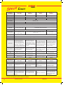
S p e c s Chart
Amplifier
Specifications
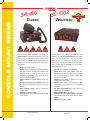
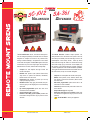
SA-441 -10F
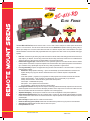
SC-411-RS -10F
MagForce
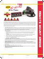
SA-430 -10F
Elite Force
Input Voltage
11-16VDC (-ground)
9-16VDC (-ground)
Input Current
17AMPS @ 14VDC
8AMPS or 16AMPS @ 14VDC
Standby Current
<250mA
<340mA
Audio Frequency
<3% (@ 1kHz dual 100W speakers)
Audio Output
80W (@ 14VDC dual 100W speakers)
Radio Input
<150mA
<7% (@ 1kHz single 100W speaker)
<3% (@ 1kHz single 100W speaker)
40W (@ 14VDC per 100W speaker)
0.75VRMS Min, 400 ohms nominal
210W RMS Max
(@ 15VDC dual 100W speakers)
105W RMS Max (@ 15VDC single 100W speaker)
180W RMS Max (@ 15VDC dual 100W speakers)
Siren Frequency
Tones/Cycle Rates
Classic
200Hz-10kHz +/- 3db
Audio Distortion
Output Power
SA-400 -10 14
Patriot
700Hz-1500Hz
Wail = 13 CPM, Yelp = 190 CPM,
Phaser = 15 CPS, Two-Tone = 60 CPM
Horn = 109 CPS, Wail = 15 CPM,
Yelp = 210 CPM, Phaser = 15 CPS,
Two-Tone = 60 CPM
Wail = 13 CPM, Yelp = 190 CPM, Phaser = 15 CPS, Two-Tone = 60 CPM
High Voltage Protection
16-18VDC siren output ceases to protect speaker, resumes when at a normal level
Short Circuit Current
50AMPS Minimum from supply circuit (supply circuit must provide for 1 second until fuse blows)
Operating Temperature
-15F to 140F
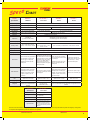
Siren Controls
Control: 6 Position rotary, push-button for
Horn and Manual, PA volume control,
dual tone toggle, +/- auxiliary input
Amplifier: Radio volume adjust, DIP
switch options
Siren Connections
Control: 5 Pin connector with #22 AWG
leads: positive, negative, control output,
backlighting input, and auxiliary input
Amplifier: 10 Pin connector: 2 positive,
2 negative, 3 speaker, 2 radio, and
control input
6 Position rotary, push button Horn, push
button Manual and Timed Override, noise
canceling microphone, PA volume control,
external radio volume control, auxiliary
input for +/- Horn, Manual, HRC2, or
Sweep operation, cutout input for +/latching cutout operation, face programmable option selection
12 Pin connector: 2 negative, 2 speaker,
2 radio cutout, 2 auxiliary input, 3 enable,
and dimming input
Control: 6 Position rotary, push-button
for Horn and Manual, PA volume control,
+/- auxiliary input
Amplifier: Radio volume adjust, cutout
input for +/- latching operation, DIP
switch options
Control: 5 Pin connector with #22 AWG
leads: positive, negative, control output,
backlighting input, and auxiliary input
Amplifier: 10 Pin connector: 2 positive,
2 negative, 2 speaker, 2 radio, control
input and cutout input
6 Position rotary, push-button for
Manual and Horn, PA volume control,
radio volume adjust, +/- auxiliary
input, and DIP switch options
9 Pin connector: 2 positive, 2 negative,
2 speaker, 2 radio, and auxiliary input
Control: 6¼”W x 2⅞”H x 1”D
Amplifier: 8”W x 2⅛”H x 6¾”D
Control Head: 6⅛”W x 2⅝”H x 1¼”D
Amplifier: 8¼”W x 8⅝H ” x 2⅛”D
Shipping Weight
6 LBS
7 LBS
5½ LBS
Ratings Met
Class A and SAEJ1849 Sound Level,
California Title 13 Configurable & KKK for
Ambulance
Class A Sound Level,
California Title 13, KKK
Class A and SAEJ1849 Sound Level, California Title 13 Configurable & KKK for
Ambulance
Size
Light Control
Specifications
Control: 6¼”W x 2⅞”H x 1”D
Amplifier: 8”W x 2⅛”H x 6¾”D
6⅛”W x 2½”H x 5⅜”D
SC-411-RS -10F
Elite Force
Light Control Voltage
9-16 VDC (- ground)
Light Controls
4 Position lever switch with LED indicators, 8 push buttons
Current (Lever Switch)
20 AMPS per circuit, 50 AMPS total
Current (Auxiliary Switches)
10 AMPS per circuit, 30 AMPS total
Light Connections
3 pin connector with exposed fuses, 10
pin connector (9 for light controls and
1 for video output) with exposed fuses,
& 2 screw down terminal for positive #6
AWG wires
All Carson sirens are intended for use by authorized personnel only. It is the user’s responsibility to ensure they understand and operate this emergency warning device
in compliance with all applicable city, state and federal laws and regulations.
www.carsonsirens.com
1.888.577.6877
19