1
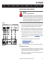
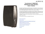
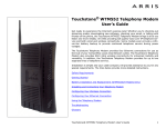
Touchstone® TM702 Telephony Modem
User’s Guide
Get ready to experience the Internet’s express lane! Whether you’re checking out
streaming media, downloading new software, checking your email, or talking with
friends on the phone, the Touchstone TM702 Telephony Modem brings it all to you
up to four times faster than standard DOCSIS 2.0 cable modems. All while providing toll quality Voice over IP telephone service. Some models even provide a
Lithium-Ion battery backup to provide continued telephone service during power
outages.
The Touchstone Telephony Modem provides an Ethernet connection for use with
either a single computer or home/office Local Area Network (LAN). Some Telephony
Modems also provide a USB connection. You can connect two separate computers
at the same time using both of these connections. In addition, the Touchstone Telephony Modem provides for up to two separate lines of telephone service.
Installation is simple and your cable company will provide assistance to you for any
special requirements. The links below provide more detailed instructions.
Safety Requirements
Getting Started
Battery Installation and Replacement (TM702G Only)
Installing and Connecting Your Telephony Modem
Installing USB Drivers on Your PC
Configuring Your Ethernet Connection
Using the Telephony Modem
Troubleshooting
Glossary
Export Regulations
Safety Requirements
European Compliance
Getting Started
About Your New Telephony Modem
What’s in the Box?
What’s on the CD?
Items You Need
Getting Service
System Requirements
Recommended Hardware
Windows
MacOS
Linux/other Unix
About this Manual
Ethernet or USB?
Ethernet
USB
Both
What About Security?
Battery Installation and Replacement (TM702G Only)
TM702G 2-cell Battery Installation and Replacement
TM702G 4-cell Battery Installation and Replacement
Installing and Connecting Your Telephony Modem
Front Panel
Rear Panel
Mounting the Telephony Modem
Tools and Materials
Location
Instructions
Wall-mounting instructions
Desktop mounting instructions
Connecting the Telephony Modem
Making Ethernet Connections
Making USB Connections
Making Telephone Connections
Installing USB Drivers on Your PC
Requirements
Installation Instructions
Installing USB Drivers on Windows 2000
Installing USB Drivers on Windows XP
Installing USB Drivers on Windows Vista
Installing Touchstone USB Drivers on Vista in 32-bit Mode
Installing Touchstone USB Drivers on Vista in 64-bit Mode
Removing USB Drivers
Removing USB Drivers (all but 64-bit Vista)
Removing USB Drivers (64-bit Vista)
Configuring Your Ethernet Connection
Requirements
How to use this chapter
TCP/IP Configuration for Windows 2000
TCP/IP Configuration for Windows XP
TCP/IP Configuration for Windows Vista
Using the Telephony Modem
Setting up Your Computer to Use the Telephony Modem
Indicator Lights for the TM702A/B Models
Wiring Problems
Indicator Lights: Normal Operation
Indicator Lights: Startup Sequence
Cable Modem Start Up Sequence
Indicator Lights for the TM702G Models
Battery Mismatch
Wiring Problems
Indicator Lights: Normal Operation
Indicator Lights: Startup Sequence
Cable Modem Start Up Sequence
Using the Reset Button
Booting from Battery
Troubleshooting
Troubleshooting USB Problems
Instructions
Glossary
Export Regulations
This product may not be exported outside the U.S. and Canada without U.S. Department of Commerce, Bureau of Export Administration authorization. Any export or re-export by
the purchaser, directly or indirectly, in contravention of U.S. Export Administration Regulation is prohibited.
Copyright © 2005–2008 ARRIS. All rights reserved.
The information in this document is subject to change without notice. The statements, configurations, technical data, and recommendations in this document are believed to be
accurate and reliable, but are presented without express or implied warranty. Users must take full responsibility for their applications of any products specified in this document.
The information in this document is proprietary to ARRIS.
ARRIS, Touchstone, and the ARRIS logo are trademarks or registered trademarks of ARRIS. All other trademarks and registered trademarks are the property of their respective holders.
Protected under the following U.S. patent: 7,031,453. Other patents pending.
Release 7
Standard 1.3
October 2008
Touchstone TM702 Telephony Modem User’s Guide
2
Safety
Getting
Started
Battery
Installation
USB
Drivers
Installation
Ethernet
Configuration
Usage
Safety Requirements
Troubleshooting
Glossary
ARRIS Telephony Modems comply with the applicable requirements for performance, construction, labeling, and information when used as outlined below:
CAUTION
Risk of shock
Mains voltages inside this unit. No user serviceable parts inside. Refer
service to qualified personnel only!
CAUTION
Potential equipment damage
Potential loss of service
Connecting the Telephony Modem to existing telephone wiring should
only be performed by a professional installer. Physical connections to
the previous telephone provider must be removed and the wiring must
be checked; there must not be any voltages. Cancellation of telephone
service is not adequate. Failure to do so may result in loss of service
and/or permanent damage to the Telephony Modem.
CAUTION
Risk of explosion
Replacing the battery with an incorrect type can cause product failure
and a risk of battery explosion. Dispose of used batteries according to
the instructions.
•
The Telephony Modem is designed to be connected directly to a telephone.
•
Do not use product near water (i.e. wet basement, bathtub, sink or near a
swimming pool, etc.), to avoid risk of electrocution.
•
Connecting the Telephony Modem to the home’s existing telephone wiring
should only be performed by a professional installer.
Touchstone TM702 Telephony Modem User’s Guide
3
Safety
Getting
Started
Battery
Installation
USB
Drivers
Installation
•
•
•
•
•
•
•
•
Ethernet
Configuration
Usage
Troubleshooting
Glossary
Avoid using and/or connecting the equipment during an electrical storm, to
avoid risk of electrocution.
Do not use the telephone to report a gas leak in the vicinity of the leak.
Do not locate the equipment within 6 feet (1.9 m) of a flame or ignition
source (i.e. heat registers, space heaters, fireplaces, etc.).
Use only power supply and power cord included with the equipment.
Equipment should be installed near the power outlet and should be easily
accessible.
The shield of the coaxial cable must be connected to earth (grounded) at the
entrance to the building in accordance with applicable national electrical installation codes. In the U.S., this is required by NFPA 70 (National Electrical
Code) Article 820. In the European Union and in certain other countries,
CATV installation equipotential bonding requirements are specified in IEC
60728-11, Cable networks for television signals, sound signals and interactive services, Part 11: Safety. This equipment is intended to be installed in
accordance with the requirements of IEC 60728-11 for safe operation.
If the equipment is to be installed in an area serviced by an IT power line
network, as is found in many areas of Norway, special attention should be
given that the installation is in accordance with IEC 60728-11, in particular
Annex B and Figure B.4.
In areas of high surge events or poor grounding situations and areas prone
to lightning strikes, additional surge protection may be required (i.e.
PF11VNT3 from American Power Conversion) on the AC, RF, Ethernet and
Phone lines.
When the Telephony Modem is connected to a local computer through USB
or Ethernet cables, the computer must be properly grounded to the building/residence AC ground network. All plug-in cards within the computer
must be properly installed and grounded to the computer frame per the
manufacturer’s specifications.
Touchstone TM702 Telephony Modem User’s Guide
4
Safety
Getting
Started
Battery
Installation
USB
Drivers
Installation
Ethernet
Configuration
Usage
Troubleshooting
Glossary
FCC Part 15
This equipment has been tested and found to comply with the requirements for a
Class B digital device under Part 15 of the Federal Communications Commission
(FCC) rules. These requirements are intended to provide reasonable protection
against harmful interference in a residential installation. This equipment generates,
uses and can radiate radio frequency energy and, if not installed and used in accordance with the instructions, may cause harmful interference to radio communications. However, there is no guarantee that interference will not occur in a
particular installation. If this equipment does cause harmful interference to radio or
television reception, which can be determined by turning the equipment off and on,
the user is encouraged to try to correct the interference by one or more of the following measures:
•
Reorient or relocate the receiving antenna.
•
Connect the equipment into an outlet on a circuit different from that to which
the receiver is connected.
•
•
Increase the separation between the equipment and receiver.
Consult the dealer or an experienced radio/TV technician for help.
Changes or modifications to this equipment not expressly approved by the party responsible for compliance could void the user’s authority to operate the equipment.
Touchstone TM702 Telephony Modem User’s Guide
5
Safety
Getting
Started
Battery
Installation
Installation
USB
Drivers
Ethernet
Configuration
Usage
Troubleshooting
Glossary
European Compliance
This product complies with the provisions of the Electromagnetic Compatibility
(EMC) Directive (89/336/EEC), the Amending Directive (92/31/EEC), the Low Voltage Directive (73/23/EEC), and the CE Marking Directive (93/68/EEC). As such,
this product bears the CE marking in accordance with the above applicable Directive(s).
A copy of the Declaration of Conformity may be obtained from: ARRIS International, Inc., 3871 Lakefield Drive, Suite 300, Suwanee, GA 30024.
As indicated by this symbol, disposal of this product or battery
is governed by Directive 2002/96/EC of the European Parliament
and of the Council on waste electrical and electronic equipment
(WEEE). WEEE could potentially prove harmful to the environment; as such, upon disposal of the Telephony Modem the
Directive requires that this product must not be disposed as
unsorted municipal waste, but rather collected separately and
disposed of in accordance with local WEEE ordinances.
This product complies with directive 2002/95/EC of the European Parliament and of the Council of 27 January 2003 on the restriction of the
use of certain hazardous substances (RoHS) in electrical and electronic equipment.
Touchstone TM702 Telephony Modem User’s Guide
6
Safety
Getting
Started
Battery
Installation
USB
Drivers
Installation
Ethernet
Configuration
Getting Started
Usage
Troubleshooting
Glossary
About Your New Telephony Modem
The Touchstone TM702 Telephony Modem is DOCSIS® 3.0 or Euro-DOCSIS™ 3.0
compliant with the following features:
•
•
•
•
Speed: much faster than dialup or ISDN service; up to four times faster than
DOCSIS 2.0 cable modems
Convenience: supports USB (if equipped) and Ethernet; both can be used
simultaneously
Flexibility: provides two independent lines of telephone service as well as
high speed data
Compatibility:
–
–
Data services: DOCSIS or Euro-DOCSIS 3.0 compliant and backwardcompatible with DOCSIS 2.0 or 1.1; supports tiered data services (if offered by your cable company)
Telephony services: PacketCable™ and Euro-PacketCable 1.5 or 1.0 compliant
What’s in the Box?
Make sure you have the following items before proceeding. Call your cable company
for assistance if anything is missing.
•
Telephony Modem
•
Battery (not all Telephony Modems have a battery)
•
•
•
•
•
•
•
Power Cord
Quick Installation Guide
Wall-Mounting Template and Instructions
USB Cable (if the Telephony Modem has a USB port)
Ethernet Cable
CD-ROM (if the Telephony Modem has a USB port)
Screws for Wall Mounting the Unit
Touchstone TM702 Telephony Modem User’s Guide
7
Safety
Getting
Started
Battery
Installation
USB
Drivers
Installation
•
Ethernet
Configuration
Usage
Troubleshooting
Glossary
End User License Agreement
What’s on the CD?
The CD provides the following items:
•
Quick Install Guide
•
USB Drivers (Windows 2000/XP/Vista)
•
•
User’s Guide
Remove USB Driver Utility
Items You Need
If you are installing the Telephony Modem yourself, make sure you have the following items on hand before continuing:
Coax Cable
•
•
•
•
Phone Cable
Telephony modem package: see What’s in the Box? for a list of items in
the package.
Coaxial cable (coax): as shown in the image to the left, this is a thin cable
with a connector on each end. It is the same kind of wire used to connect to
your television for cable TV. You can buy coax from any electronics retailer
and many discount stores; make sure it has connectors on both ends. There
are two types of connectors, slip-on and screw-on; the screw-on connectors
are best for use with your Telephony Modem. The coax should be long
enough to reach from your Telephony Modem to the nearest cable outlet.
Note: For best performance, use high-quality RG-6 type coax cable and minimize or eliminate splitters between the cable jack and the Telephony Modem.
Phone Cable: as shown in the image to the left, this is a standard phone
cable with standard phone connectors (RJ11 type) on both ends. You can
buy phone cables from any electronics retailer and many discount stores.
Splitter (optional): provides an extra cable connection by splitting a single outlet into two. You may need a splitter if you have a TV already connected to the cable outlet that you want to use. You can buy a splitter from
any electronics retailer and most discount stores; you may also need a short
piece of coax cable (with connectors); use it to connect the splitter to the
cable outlet and then connect the Telephony Modem and TV to the splitter.
Touchstone TM702 Telephony Modem User’s Guide
8
Safety
Getting
Started
Battery
Installation
USB
Drivers
Installation
•
Ethernet
Configuration
Usage
Troubleshooting
Glossary
Note: A splitter effectively cuts the signal in half and sends each half to its
two outputs. Using several splitters in a line may deteriorate the quality of
your television, telephone, and/or internet connection.
Information packet: your cable company should furnish you with a packet
containing information about your service and how to set it up. Read this information carefully and contact your cable company if you have any questions.
Getting Service
Before trying to use your new Telephony Modem, contact your local cable company
to establish an Internet account and telephone service. When you call, have the
following information ready:
•
•
the Telephony Modem serial number and MAC addresses of the unit (printed
on a sticker on the bottom of the Telephony Modem)
the model number of the Telephony Modem
Save this information for future use. In addition, you should ask your cable company the following questions:
•
•
•
•
•
Do you have any special system requirements or files that I need to download after I am connected?
When can I start using my Telephony Modem?
Do I need a user ID or password to access the Internet or my e-mail?
Will my phone number(s) change?
What new calling features will I have and how do I use them?
Touchstone TM702 Telephony Modem User’s Guide
9
Safety
Getting
Started
Battery
Installation
Installation
USB
Drivers
Ethernet
Configuration
Usage
Troubleshooting
Glossary
System Requirements
The Touchstone Telephony Modem operates with most computers. The following
describes requirements for each operating system; see the documentation for your
system for details on enabling and configuring networking.
To use the Telephony Modem, you need DOCSIS or Euro-DOCSIS high-speed Internet service from your cable company, as appropriate. Telephone service requires
that the cable company has PacketCable or Euro-PacketCable support.
Recommended Hardware
The following hardware configuration is the minimum recommended. Computers
not meeting this configuration can still work with the TM702, but may not be able
to make maximum use of TM702 throughput.
CPU: P4, 3GHz or faster
RAM: 1GB or greater
Hard drive: 7200 RPM or faster
Ethernet: Gig-E (1000BaseT)
Windows
Ethernet connection: Windows 2000, Windows XP, or Windows Vista
USB connection (if equipped): Windows 2000, Windows XP, or Windows Vista
MacOS
Ethernet connection only: System 7.5 to MacOS 9.2 (Open Transport recommended) or MacOS X
Linux/other Unix
Ethernet connection only: Hardware drivers, TCP/IP, and DHCP must be enabled in
the kernel
Touchstone TM702 Telephony Modem User’s Guide
10
Safety
Getting
Started
Battery
Installation
Installation
USB
Drivers
Ethernet
Configuration
Usage
Troubleshooting
Glossary
About this Manual
This manual covers all of the different TM702 models. Your model may not have all
of the capabilities outlined in this manual. To determine which model you have purchased, refer to the image at the left. The model number is on the label affixed to
the Telephony Modem.
Ethernet or USB?
There are two ways to connect your computer (or other equipment) to the Telephony Modem. The following will help you decide which is best for you:
Model
Number
Ethernet
Ethernet is a standard method of connecting two or more devices into a Local Area
Network (LAN). Use the Ethernet connection if your computer has built-in Ethernet
hardware, does not use Windows, or you want to share the Telephony Modem connection with several computers.
Note:
To connect two or more computers to the Ethernet port, you will need a
hub or broadband router (available at computer retailers).
The Telephony Modem package comes with a 6-foot (1.9m) Ethernet cable (the
connectors look like wide telephone connectors); you can purchase more cables if
necessary at a computer retailer. If you are connecting the Telephony Modem
directly to a computer, or to an Ethernet hub or broadband router with a cross-over
switch, ask for Category 5 (CAT5) straight-through cable. If you are connecting the
Telephony Modem to an Ethernet hub or broadband router without a crossover
switch, ask for a Category 5 crossover cable.
USB
Ethernet Cable
USB Cable
USB (Universal Serial Bus) is meant for connecting a variety of accessories, such as
keyboards, mice, printers, and communications devices (including Telephony
Modems) to a single computer. Use the USB connection if you have only one computer, and the computer is using a Windows operating system (Windows 2000 or
later), and has no built-in Ethernet hardware. Telephony Modems with USB ports
include a 5-foot (1.6m) USB cable.
Touchstone TM702 Telephony Modem User’s Guide
11
Safety
Getting
Started
Battery
Installation
USB
Drivers
Installation
Ethernet
Configuration
Usage
Troubleshooting
Glossary
Both
If you have two or more computers, you can connect one computer to the Telephony Modem’s USB port and one or more other computers to the Ethernet port.
To connect two or more computers to the Ethernet port, you will need a hub or
broadband router (available at computer retailers).
For more information about connecting two or more computers, contact your cable
service provider.
What About Security?
Having a high-speed, always-on connection to the Internet requires a certain
amount of responsibility to other Internet users—including the need to maintain a
reasonably secure system. While no system is 100% secure, you can use the following tips to enhance your system’s security:
•
•
•
•
•
•
•
Keep your operating system updated with the latest security patches. Run
the system update utility at least weekly.
Keep your email program updated with the latest security patches. In addition, avoid opening email containing attachments, or opening files sent
through chat rooms, whenever possible.
Install a virus checker and keep it updated.
Avoid providing web or file-sharing services over your Telephony Modem.
Besides certain vulnerability problems, most cable companies prohibit running servers on consumer-level accounts and may suspend your account for
violating your terms of service.
Use the cable company’s mail servers for sending email.
Avoid using proxy software unless you are certain that it is not open for
abuse by other Internet users (some are shipped open by default). Criminals can take advantage of open proxies to hide their identity when breaking into other computers or sending spam. If you have an open proxy, your
cable company may suspend your account to protect the rest of the network.
If you connect your Telephony Modem to a wireless LAN, make sure you
enable security and encryption on the wireless hub (for the same reasons
that you should run only secured proxies). Consult the documentation and
technical support of the wireless equipment provider for help.
Touchstone TM702 Telephony Modem User’s Guide
12
Safety
Getting
Started
Battery
Installation
USB
Drivers
Installation
Ethernet
Configuration
Usage
Troubleshooting
Glossary
Battery Installation and Replacement
(TM702G Only)
TM702G Telephony Modems may optionally include one of two types of Lithium-Ion
batteries: a 2-cell battery or a 4-cell battery.
For safety and regulatory purposes, batteries are shipped outside of the Telephony
Modem and must be installed.
2-cell Battery
Identify the battery type using the photos to the left and use the proper installation procedure:
•
TM702G 2-cell Battery Installation and Replacement
•
TM702G 4-cell Battery Installation and Replacement
Note: The 2-cell battery may be light grey or black.
Note: The 4-cell battery is longer than the 2-cell battery, and has a strap
between the guides. It also may be light grey or black.
4-cell Battery
Touchstone TM702 Telephony Modem User’s Guide
13
Safety
Getting
Started
Battery
Installation
USB
Drivers
Installation
Ethernet
Configuration
Usage
Troubleshooting
Glossary
TM702G 2-cell Battery Installation and Replacement
This model of the Telephony Modem has the ability to provide battery backup in
the event of a local power loss. The battery backup is not intended to take the place
of AC power. Use this procedure to install and to replace the backup batteries.
1
Insert a finger into the latch opening, press down and pull back on the latch
holding the battery door (on the bottom of the Telephony Modem). Pull the
door toward you. Set the door aside in a safe place.
2
Hold the battery pack so that the guides on the battery align with the slots
on the Telephony Modem and slide the battery into the bay. The diagram on
the left shows the proper orientation.
Latch End
Battery Slot
Note: Batteries will not insert completely into the Telephony Modem if not
oriented correctly. The battery should slide into the bay without significant
force. Line up the guides on the battery with the slots in the battery bay.
Battery Guide
Touchstone TM702 Telephony Modem User’s Guide
14
Safety
Getting
Started
Battery
Installation
USB
Drivers
Installation
Battery
Opening
3
4
Receiver
Slots
Note:
Hinge Tabs
Ethernet
Configuration
Usage
Troubleshooting
Glossary
Push the battery pack into the bay until it seats into place. The following
diagram shows a Telephony Modem with a 2-cell battery pack installed. If
you are taking the battery out of the Telephony Modem, position
your finger in the battery opening area and use leverage to dislodge
the battery while pulling it straight back.
Note: The Telephony Modem will not begin operating until you apply AC
power.
Replace the door. To do so, place the hinge tabs of the battery door into the
receiver slots inside the Telephony Modem battery compartment on the
opposite end of the battery opening slot. Rotate the door toward the unit
until the latch snaps back into place.
Telephony Modems use a Lithium-Ion battery pack. Please recycle or dispose of the battery responsibly and in accordance with local ordinances.
Touchstone TM702 Telephony Modem User’s Guide
15
Safety
Getting
Started
Battery
Installation
USB
Drivers
Installation
Ethernet
Configuration
Usage
Troubleshooting
Glossary
TM702G 4-cell Battery Installation and Replacement
Use this procedure to install or replace a 4-cell backup battery.
1
Insert a finger into the latch opening, press down and pull back on the latch
holding the battery door (on the bottom of the Telephony Modem). Pull the
door toward you. Set the door aside in a safe place.
CAUTION
Risk of equipment damage
Improperly inserting the battery may damage the battery connector in
the Telephony Modem. Carefully follow the instructions in the next step
to avoid damage.
Latch End
2
Battery Slot
Battery Guide
Battery
Pull Strap
Hold the battery pack so that the guides on the battery align with the slots
on the Telephony Modem and slide the battery into the bay. The diagram on
the left shows the proper orientation.
Note: Batteries will not insert completely into the Telephony Modem if not
oriented correctly. The battery should slide into the bay without significant
force. Line up the slots in the battery bay with the guides on the battery
and apply even pressure on both ends of the battery.
WRONG
WRONG
Touchstone TM702 Telephony Modem User’s Guide
RIGHT
16
Safety
Getting
Started
Battery
Installation
USB
Drivers
Installation
3
4
Ethernet
Configuration
Usage
Troubleshooting
Glossary
Push the battery pack into the bay until it latches into place. The diagram to
the left shows a Telephony Modem with a 4-cell battery pack installed. If
you are taking the battery out of the Telephony Modem, use the battery pull strap to dislodge the battery.
Note: The Telephony Modem will not begin operating until you apply AC
power.
Replace the door. To do so, place the tabs of the battery door into the slot
on the Telephony Modem battery compartment. Rotate the door toward the
front of the Telephony Modem until the latch snaps back into place.
Note: Some Telephony Modem models use a Lithium-Ion battery pack.
Please recycle or dispose of the battery responsibly and in accordance with
local ordinances.
Receiver
Slots
Hinge Tabs
Touchstone TM702 Telephony Modem User’s Guide
17
Safety
Getting
Started
Battery
Installation
USB
Drivers
Installation
Ethernet
Configuration
Usage
Troubleshooting
Installing and Connecting Your
Telephony Modem
Glossary
Before you start, make sure that:
•
•
•
You have contacted your cable company and verified that they provide data
and telephone service using standard DOCSIS technology.
You have all the Items You Need.
Cable, phone, and power outlets are available near the computer. If a cable
outlet is not conveniently located, your cable company can install a new one.
If you have ordered service, your cable company should configure the Telephony
Modem automatically. You need only follow the instructions in this section to install
and connect the Telephony Modem.
CAUTION
Risk of equipment damage
Only qualified installation technicians should connect the Telephony
Modem to house wiring. Incumbent telephone service must be physically disconnected at the outside interface box before making any connections.
Touchstone TM702 Telephony Modem User’s Guide
18
Getting
Started
Safety
Battery
Installation
USB
Drivers
Installation
Ethernet
Configuration
Usage
Troubleshooting
Glossary
Front Panel
B D F
H
The front of the Telephony Modem provides the following indicators.
A
Battery (TM702G only): indicates battery status
C
Telephone 1: indicates status of line 1
B
D
E
A C E
G
F
G
H
Link: indicates Ethernet or USB (if equipped) connectivity between the Telephony Modem and computer
Online: indicates internet data transmission status
US: indicates upstream connectivity
DS: indicates downstream connectivity
Power: indicates whether AC power is available to the unit
Rear Panel
TM702G
The rear of the Telephony Modem has the following connectors and controls:
A
B
C
A B C
Telephone 2: indicates status of line 2
D
E
F
G
D
E
F
G
Tel 1/2 (grey): connector for the first phone line (or both lines of a 2-line
phone).
Tel 2 (grey): connector for the second phone line.
Reset button: resets the Telephony Modem as if you power cycled the unit.
Use a pointed non-metallic object to press this button.
Ethernet connector (yellow): for use with a computer or home network LAN
connection.
USB connector (blue, if equipped): for use with a computer USB connection.
Cable: connector for the coax cable.
Power: connector for the power cord.
TM702A/B
Touchstone TM702 Telephony Modem User’s Guide
19
Safety
Getting
Started
Battery
Installation
USB
Drivers
Installation
Ethernet
Configuration
Usage
Troubleshooting
Glossary
Mounting the Telephony Modem
You can either mount the Telephony Modem on a wall or place it on a desktop. For
wall-mount applications, you can mount the Telephony Modem with the indicators
facing upward (vertical) or to the side (horizontal).
Tools and Materials
For wall-mounted installations, make sure you have the following tools and materials before proceeding:
•
•
•
•
•
for mounting on drywall: Two 1/4” (6mm) drywall anchors and a drill with
1/4” (6mm) bit (not included)
for mounting on plywood or studs: two #6 x 1.5” (38.1 mm) self tapping
screws (included)
screwdriver (flat-blade or Phillips, depending on what kind of screws you
use)
wall-mount template (included with the Telephony Modem Quick Installation Guide)
transparent tape (for temporarily securing the mounting template to the
wall)
Location
Always position the Telephony Modem:
•
•
within reach of an AC outlet. The power cord must reach the outlet without
stretching and without adding extension cords.
near a cable outlet (to avoid long cable runs).
Touchstone TM702 Telephony Modem User’s Guide
20
Safety
Getting
Started
Battery
Installation
USB
Drivers
Installation
Ethernet
Configuration
Usage
Troubleshooting
Glossary
Instructions
Wall-mounting instructions
Note:
Step 1
Step 2
1
2
3
Step 3
Step 4
4
5
When mounting the Telephony Modem on drywall, try to position the
Telephony Modem so at least one of the screws are fastened to a stud.
This may prevent the Telephony Modem from pulling out of the wall in
the future. To prevent overheating of the Telephony Modem, do not block
the ventilation holes on the sides of the unit.
Position the mounting template on the surface where you intend to mount
the Telephony Modem and secure in place with transparent tape.
Drill holes through the template in the specified locations for the mounting
screws. After drilling holes, remove the template from the surface.
If using drywall anchors, set them into the wall. Then, drive the screws into
the wall leaving a gap of about 1/8” (3 mm) between the screw head and
the wall. If not using anchors, just drive the screws.
Orient the Telephony Modem with the indicator lights facing up or right, as
desired. Slip both mounting slots (in the back of the Telephony Modem) over
the screws, then slide the case down until the narrow end of the keyhole slot
contacts the screw shaft.
Proceed to Connecting the Telephony Modem.
Desktop mounting instructions
1
Position the Telephony Modem so that:
•
air flows freely around it
•
it will not fall to the floor if bumped or moved
•
2
•
the back faces the nearest wall
the ventilation holes on the side of the unit are not blocked
Proceed to Connecting the Telephony Modem.
Touchstone TM702 Telephony Modem User’s Guide
21
Getting
Started
Safety
Battery
Installation
USB
Drivers
Installation
Ethernet
Configuration
Usage
Troubleshooting
Glossary
Connecting the Telephony Modem
WARNING
Risk of injury or equipment damage
Connecting the Telephony Modem to the home’s existing telephone
wiring should only be performed by a professional installer. Physical connections to the previous telephone provider must be removed and the
wiring must be checked; there must not be any voltage. Cancellation of
telephone service is not adequate. Failure to do so may result in loss of
service and/or permanent damage to the Telephony Modem.
TM702G
A B C
1
D
E
F
G
2
3
TM702A/B
Note:
Connect one end of the coax cable to the cable outlet or splitter, and the
other end to the Telephony Modem’s Cable connector (F). Tighten the connections by hand, then tighten an additional 1/8 turn with a wrench.
Note: For best performance, use high-quality RG-6 type coax cable and minimize or eliminate splitters between the cable jack and the Telephony Modem.
Insert the plug from the power cord into the Power connector on the Telephony Modem (G) and insert the power cord into a convenient AC outlet.
The Power light on the front of the Telephony Modem lights up, then flashes
once (refer to the LED table on page 44). See Troubleshooting if the Power
light does not turn on.
After connecting the coax cable and power, proceed as needed:
•
•
Making Ethernet Connections OR
Making USB Connections (if equipped)
Do not connect the same computer to both the Ethernet and USB ports.
Making Ethernet Connections
4
Connect one end of the yellow Ethernet cable to the yellow port on the back
of the Telephony Modem labeled “Ethernet 10/100,” (D) and the other end
to the Ethernet port on a computer, hub, or broadband router.
Note: If you are connecting to a computer, use the Ethernet cable included
in the Telephony Modem package.
Touchstone TM702 Telephony Modem User’s Guide
22
Safety
Getting
Started
Battery
Installation
USB
Drivers
Installation
Ethernet
Configuration
Usage
Troubleshooting
Glossary
Making USB Connections
5
(Telephony Modems with USB ports only) Connect one end of the blue USB
cable to the USB port on the computer, and the other end to the blue USB
port on the back of the Telephony Modem (E).
Your computer should detect the Telephony Modem and begin installing the
drivers. See Installing USB Drivers on Your PC for driver installation details.
Making Telephone Connections
6
Connect one end of the telephone cable to one of the grey telephone ports
on the back of the Telephony Modem (A or B). Connect the other end to the
telephone.
Note: If you have a phone with two separate lines on a single RJ-14 cord,
plug it into the port labeled “Tel 1/2”.
Touchstone TM702 Telephony Modem User’s Guide
23
Safety
Getting
Started
Battery
Installation
USB
Drivers
Installation
Ethernet
Configuration
Usage
Troubleshooting
Installing USB Drivers on Your PC
Glossary
When you plug the Telephony Modem into the PC’s USB port, Windows automatically detects the hardware and begins installing the USB drivers.
This procedure does not explain how to provision the Telephony Modem or otherwise initiate actual service.
The latest USB drivers and documentation are available on line at
http://www.arrisi.com/support/usb/index.asp
Note:
Not all Telephony Modems are equipped with a USB port.
Requirements
Make sure you have the following before attempting to install the USB drivers:
• PC with:
— CD-ROM drive
— at least one free USB port
— one of: Windows 2000, Windows XP, or Windows Vista (Windows 95,
Windows 98, and Windows NT are not supported)
•
•
— ARRIS USB Driver CD
USB A/B Cable of appropriate length (a cable is included in your Telephony
Modem package)
(for installations not using DHCP) IP address, subnet, gateway, and DNS information
Installation Instructions
Select the link for your operating system to see the installation instructions.
•
Installing USB Drivers on Windows 2000
•
Installing USB Drivers on Windows Vista
•
Installing USB Drivers on Windows XP
Touchstone TM702 Telephony Modem User’s Guide
24
Safety
Getting
Started
Battery
Installation
USB
Drivers
Installation
Ethernet
Configuration
Usage
Troubleshooting
Glossary
Installing USB Drivers on Windows 2000
Follow these steps to install USB drivers on Windows 2000.
1
2
3
Make sure the Telephony Modem is on (the Power light should be on). If not,
connect the AC adapter as described in Connecting the Telephony Modem.
Insert the CD that came with the Telephony Modem package into the CDROM drive.
Plug the appropriate end of the USB cable into the Telephony Modem and the
other end into the computer’s USB port.
The following window appears, indicating that the PC has detected a new
USB device:
4
Wait for the system to start the installation wizard and display the following
window (there may be a short delay):
Touchstone TM702 Telephony Modem User’s Guide
25
Safety
Getting
Started
Battery
Installation
USB
Drivers
Installation
5
Ethernet
Configuration
Usage
Troubleshooting
Glossary
Click the Next button.
The wizard prompts you for the location of the drivers.
Note: The dialog indicates that the wizard is looking for the ARRIS RNDIS
(Remote Network Device Interface Specification) driver for the Telephony
Modem.
Touchstone TM702 Telephony Modem User’s Guide
26
Safety
Getting
Started
Battery
Installation
USB
Drivers
Installation
6
Ethernet
Configuration
Usage
Troubleshooting
Glossary
Select “Search for a suitable driver for my device”, unless you want to use
the second option to choose a specific driver, then click the Next button.
The wizard displays a list of search options.
Touchstone TM702 Telephony Modem User’s Guide
27
Safety
Getting
Started
Battery
Installation
USB
Drivers
Installation
7
Ethernet
Configuration
Usage
Troubleshooting
Glossary
Make sure the CD-ROM option is selected (checked), then click the Next
button.
The wizard searches the specified locations, then displays the location and
name of the appropriate driver.
Note: If the wizard can not find the CD drive, and the CD is inserted properly, follow these steps:
a. On the Windows desktop, open “My Computer” and note the letter of the
Compact Disc (or CD-ROM) drive (on most systems, the CD drive is at
D: or E:)
b. Return to the Found New Hardware Wizard, and click the Back button.
The wizard displays the previous screen, shown in step 6.
c. Select “Specify a Location,” then choose the drive letter that corresponds
to the CD drive from the menu.
d. Click the Next button.
You should now see the screen shown above. If not, contact your cable
company for help.
Touchstone TM702 Telephony Modem User’s Guide
28
Safety
Getting
Started
Battery
Installation
USB
Drivers
Installation
8
Ethernet
Configuration
Usage
Troubleshooting
Glossary
Click the Next button.
The wizard installs the drivers, then displays a window indicating that the
installation is complete.
9 Click the Finish button.
Touchstone TM702 Telephony Modem User’s Guide
29
Safety
Getting
Started
Battery
Installation
USB
Drivers
Installation
Ethernet
Configuration
Usage
Troubleshooting
Glossary
Installing USB Drivers on Windows XP
Follow these steps to install USB drivers on Windows XP.
1
2
3
Make sure the Telephony Modem is on (the Power light should be on). If
not, connect the AC adapter as described in Connecting the Telephony
Modem.
Insert the CD that came with the Telephony Modem package into the CDROM drive.
Plug the appropriate end of the USB cable into the Telephony Modem and the
other end into the computer’s USB port.
The following window appears, indicating that the PC has detected a new
USB device:
Touchstone TM702 Telephony Modem User’s Guide
30
Safety
Getting
Started
Battery
Installation
USB
Drivers
Installation
Ethernet
Configuration
4
Click the Next button.
5
Click the Next button.
6
Click the Finish button.
Usage
Troubleshooting
Glossary
In some cases, you may see the following screen. Choose the version on
the CD, indicated by the drive letter preceding the file name.
The wizard begins searching for and installing the drivers, then displays a
window indicating that the installation is complete.
Touchstone TM702 Telephony Modem User’s Guide
31
Safety
Getting
Started
Battery
Installation
USB
Drivers
Installation
Ethernet
Configuration
Usage
Troubleshooting
Glossary
Installing USB Drivers on Windows Vista
Follow these steps to install USB drivers on Windows Vista.
Installing Touchstone USB Drivers on Vista in 32-bit Mode
When running Vista in 32-bit mode, simply connect your PC to the Touchstone Telephony Modem or Cable Modem. The Vista Hardware Installation Wizard finds the
correct 32-bit USB driver and installs it for you.
Installing Touchstone USB Drivers on Vista in 64-bit Mode
When running Vista in 64-bit mode, you must install an updated Vista USB 1.1
driver. Follow these steps to obtain and install the driver.
1
2
3
4
Download the zipped Vista USB driver from the ARRIS website at the following link:
http://www.arrisi.com/support/usb/index.asp
Unzip the files to a directory that can be referenced later (Step 8) during the
installation of the USB driver.
Connect the USB cable between the Touchstone Cable Modem or Telephony
Modem and personal computer running Vista.
When the Found New Hardware screen is presented, select the “Locate and
install driver software (recommended)” option.
Touchstone TM702 Telephony Modem User’s Guide
32
Safety
Getting
Started
Battery
Installation
USB
Drivers
Installation
5
6
7
Ethernet
Configuration
Usage
Troubleshooting
Glossary
When you see a window with the heading “Windows needs your permission
to continue,” click Continue to proceed.
Vista tries to locate the new USB driver, and displays a “Installing device
driver software” at the bottom right of the screen. Vista will not find the
driver, and displays the following window. At the prompt, select I don’t
have the disc. Show me other options.
Select Browse my computer for driver software (advanced).
Touchstone TM702 Telephony Modem User’s Guide
33
Safety
Getting
Started
Battery
Installation
USB
Drivers
Installation
Ethernet
Configuration
Usage
Troubleshooting
Glossary
8
Browse to the directory that you set up in step 2. Select Next.
9
Once Vista finds the driver software in the directory specified in step 8, installation is in progress as shown below.
Touchstone TM702 Telephony Modem User’s Guide
34
Safety
Getting
Started
Battery
Installation
Installation
USB
Drivers
Ethernet
Configuration
Usage
Troubleshooting
Glossary
10 The Found New Hardware wizard should display the following screen when
the USB driver has been successfully installed. Select Close.
11 Once the installation is completed successfully, Vista displays an icon with the
message “ARRIS TOUCHSTONE DEVICE, Device driver software installed
successfully” at the bottom right corner of the screen.
Touchstone TM702 Telephony Modem User’s Guide
35
Safety
Getting
Started
Battery
Installation
USB
Drivers
Installation
Ethernet
Configuration
Usage
Troubleshooting
Glossary
Removing USB Drivers
You use a Remove utility to remove ARRIS USB drivers. The 64-bit version of Vista
uses a special utility; other versions of Windows use a single utility.
Removing USB Drivers (all but 64-bit Vista)
If you connect the Telephony Modem USB to your computer before inserting the
ARRIS driver installation CD, Windows may install a “composite” USB driver that
does not properly support the Telephony Modem. To correct this problem, you must
first remove the composite driver using the Remove utility on the ARRIS driver installation CD. Follow these steps to use the Remove utility:
1
Insert the ARRIS driver installation CD.
3
Start the Remove utility by double-clicking it in the window.
2
Navigate to the CD drive:
The Remove utility prompts you to click OK to remove the USB driver, or
Cancel to quit.
Touchstone TM702 Telephony Modem User’s Guide
36
Safety
Getting
Started
Battery
Installation
USB
Drivers
Installation
Ethernet
Configuration
Usage
Troubleshooting
Glossary
4
Click the OK button.
5
Leave the CD in the drive, reconnect the Telephony Modem, and install the
USB driver as appropriate for your operating system.
The Remove utility displays the following message:
Removing USB Drivers (64-bit Vista)
Follow these steps to uninstall the 64-bit USB driver, if necessary.
1
2
3
4
5
6
7
If you no longer have the USB driver, download the zipped Vista USB driver
from the ARRIS website at the following link:
http://www.arrisi.com/support/usb/index.asp
If necessary, unzip the files to a directory that can be accessed for the uninstallation.
Connect the USB cable between the Touchstone Cable Modem or Telephony
Modem and personal computer running Vista.
Open the directory created in step 2 (or during the original driver installation, if you kept it).
Locate the file remove.exe.
Right-click on the remove.exe file, and select Run as administrator from
the drop-down menu. Enter the administrator password, if prompted.
Follow the instructions as prompted to remove the driver.
Touchstone TM702 Telephony Modem User’s Guide
37
Safety
Getting
Started
Battery
Installation
USB
Drivers
Installation
Ethernet
Configuration
Usage
Troubleshooting
Glossary
Configuring Your Ethernet Connection
If your computer is equipped with a LAN card providing an Ethernet connection,
you may have to configure your computer’s TCP/IP settings. The steps that follow
will guide you through setting your computer’s TCP/IP settings to work with the
Telephony Modem.
Requirements
Make sure you have the following before attempting to configure your Ethernet connection:
•
•
•
Computer with:
— one of: Windows 2000, Windows XP, or Windows Vista
— Ethernet interface
Ethernet cable (supplied)
IP address, subnet, gateway, and DNS information for installations not using
DHCP
How to use this chapter
The following list shows the procedures for modifying the TCP/IP settings on the
computer. The procedure is slightly different depending on the operating system
that you are using. Please ensure you are using the correct steps for the operating
system on your computer. Follow the links below for instructions to configure your
ethernet connection on your operating system.
•
TCP/IP Configuration for Windows 2000
•
TCP/IP Configuration for Windows Vista
•
TCP/IP Configuration for Windows XP
Touchstone TM702 Telephony Modem User’s Guide
38
Safety
Getting
Started
Battery
Installation
USB
Drivers
Installation
Ethernet
Configuration
Usage
Troubleshooting
Glossary
TCP/IP Configuration for Windows 2000
Follow these steps to configure the TCP/IP settings on a Windows 2000 operating
system.
Note:
1
2
Dialog boxes shown on your computer may differ slightly from those
shown in this procedure.
From the computer, select Start > Settings > Network and Dial-up Connections > Local Area Connection.
In the Local Area Connections Properties window, highlight TCP/IP by clicking on it one time, then click on Properties.
Note: If your computer has more than one Ethernet card, you may have to
select the appropriate Ethernet card in the Connect using: area of the Local
Area Connection Properties window.
Touchstone TM702 Telephony Modem User’s Guide
39
Safety
Getting
Started
Battery
Installation
USB
Drivers
Installation
Ethernet
Configuration
Usage
Troubleshooting
Glossary
3
Click Obtain an IP address automatically and Obtain DNS server address automatically, then click OK.
4
Click OK to accept the new settings, and OK again to close the Configuration window.
5
You may have to restart your computer in order for your computer to obtain
a new IP address from the network.
Touchstone TM702 Telephony Modem User’s Guide
40
Safety
Getting
Started
Battery
Installation
USB
Drivers
Installation
Ethernet
Configuration
Usage
Troubleshooting
Glossary
TCP/IP Configuration for Windows XP
Follow these steps to configure the TCP/IP settings on a Windows XP operating system.
Note:
1
2
Dialog boxes shown on your computer may differ slightly from those
shown in this procedure.
From the computer, select Start > Settings > Control Panel and double
click on the Network Connections icon in the Control Panel.
Click the Configuration tab in the Network window to display the list of
Network Adapters.
Touchstone TM702 Telephony Modem User’s Guide
41
Safety
Getting
Started
Battery
Installation
USB
Drivers
Installation
Ethernet
Configuration
Usage
Troubleshooting
Glossary
3
Highlight TCP/IP by clicking on it one time, then click on Properties.
4
Click the IP Address tab, click Obtain an IP address automatically, then
click OK.
5
Click OK to accept the new settings, and OK again to close the Configuration window.
Touchstone TM702 Telephony Modem User’s Guide
42
Safety
Getting
Started
Battery
Installation
USB
Drivers
Installation
6
Ethernet
Configuration
Usage
Troubleshooting
Glossary
You may have to restart your computer in order for your computer to obtain
a new IP address from the network.
TCP/IP Configuration for Windows Vista
Follow these steps to configure the Ethernet interface for use with Touchstone products.
1
Open the Vista Control Panel.
2
Double-click Network and Sharing Center.
Touchstone TM702 Telephony Modem User’s Guide
43
Safety
Getting
Started
Battery
Installation
USB
Drivers
Installation
Ethernet
Configuration
Usage
Troubleshooting
Glossary
3
Click Manage network connections. If prompted for a connection, choose
Local Area Connection.
4
Double-click the Local Area Connection to open the Status window:
5
If Windows requests permission to continue, click Continue.
6
Click Properties.
Touchstone TM702 Telephony Modem User’s Guide
44
Safety
Getting
Started
Battery
Installation
USB
Drivers
Installation
Ethernet
Configuration
Usage
Troubleshooting
Glossary
7
Double-click Internet Protocol Version 4 (TCP/IPv4).
8
Select Obtain an IP address automatically and Obtain DNS server
address automatically, unless instructed otherwise by your cable provider.
9
Click OK to close the Properties windows.
Touchstone TM702 Telephony Modem User’s Guide
45
Safety
Getting
Started
Battery
Installation
USB
Drivers
Installation
Ethernet
Configuration
Usage
Troubleshooting
Using the Telephony Modem
Glossary
This chapter describes the controls and features available on the Touchstone Telephony Modem, and covers basic troubleshooting procedures.
•
Setting up Your Computer to Use the Telephony Modem
•
Indicator Lights for the TM702G Models
•
•
•
Indicator Lights for the TM702A/B Models
Using the Reset Button
Booting from Battery
Setting up Your Computer to Use the
Telephony Modem
Follow the instructions in the information packet supplied by your cable company.
Contact your cable company if you need help setting up your computer.
Touchstone TM702 Telephony Modem User’s Guide
46
Safety
Getting
Started
Battery
Installation
Installation
USB
Drivers
Ethernet
Configuration
Usage
Troubleshooting
Glossary
Indicator Lights for the TM702A/B Models
The Touchstone Telephony Modem has seven indicator lights to assist in troubleshooting.
Wiring Problems
If the Telephony Modem begins flashing all its lights for more than 10 seconds, this
indicates a problem with the telephone wiring—the red and green wires may be
shorted (touching), or there may be undesired voltage on the lines. If this pattern
persists for more than 10 seconds, disconnect the telephone lines from the Telephony Modem, then call a wiring technician for assistance.
Indicator Lights: Normal Operation
The following table shows light patterns during normal operation.
Mode
Power
DS
US
Online
Link
Tel. 1/
Tel. 2
On = Computer
On =
On =
On =
Connected
Connected to Connected to On = Internet
On-hook
Available
the Internet the Internet
Off = Computer
Flash =
not connected
Flash = Not
Flash = Not Off = Internet
Off-hook
connected to connected to not available
Flash =
the Internet the Internet
Computer
Off = disabled
Activity
AC Power
Good
On
No AC Power
Off
Off
Off
Off
Off
Off
Firmware
Upgrade
On
Flash
Flash
On
(normal
operation)
(normal
operation)
Touchstone TM702 Telephony Modem User’s Guide
47
Safety
Getting
Started
Battery
Installation
USB
Drivers
Installation
Ethernet
Configuration
Usage
Troubleshooting
Glossary
Indicator Lights: Startup Sequence
The following table shows the Telephony Modem light patterns during each phase
of the startup sequence. There are two phases of startup; the Telephony phase and
the cable modem phase. Both are outlined below.
Power, DS,
US, Online
Link
Off
Flash
Telephone
Description
1
2
Off
Off
Off
No power to Cable Modem
Flash
Flash
Flash
Power-on Self Test
See “Cable Modem Start Up Sequence” Below
On
On
Flash
Off
Retrieving telephone network
information
On
On
Off
Flash
Retrieving telephone line information
On
On
Flash
Flash
Activating telephone service
Normal Operation
Cable Modem Start Up Sequence
DS
US
Online
Link
On
Flash
Off
Off
On
On
Flash
On
Off
On
Off
Flash
On
Off
Off
On
Description
Downstream search
Downstream found; upstream search
Downstream and Upstream found; retrieving
setup information from cable operator
Touchstone TM702 Telephony Modem User’s Guide
Ready for service
48
Safety
Getting
Started
Battery
Installation
Installation
USB
Drivers
Ethernet
Configuration
Usage
Troubleshooting
Glossary
Indicator Lights for the TM702G Models
The Touchstone Telephony Modem has eight indicator lights to assist in troubleshooting. Note that not all models have a Battery light.
Battery Mismatch
If the Telephony Modem alternates flashing the Battery light and all other lights, the
installed battery is incompatible with the Telephony Modem. Remove the battery
and install one of the batteries described in Battery Installation and Replacement
(TM702G Only).
Wiring Problems
If the Telephony Modem begins flashing all its lights for more than 10 seconds, this
indicates a problem with the telephone wiring—the red and green wires may be
shorted (touching), or there may be undesired voltage on the lines. If this pattern
persists for more than 10 seconds, disconnect the telephone lines from the Telephony Modem, then call a wiring technician for assistance.
Touchstone TM702 Telephony Modem User’s Guide
49
Safety
Getting
Started
Battery
Installation
Installation
USB
Drivers
Ethernet
Configuration
Usage
Troubleshooting
Glossary
Indicator Lights: Normal Operation
The following table shows light patterns during normal operation.
Mode
AC Power
Good
Power
On
DS
US
On =
Connected
to the
Internet
On =
Connected
to the
Internet
Online
On =
Internet
Available
Off =
Flash = Not Flash = Not
connected connected Internet not
available
to the
to the
Internet
Internet
Link
On =
Computer
Connected
Off =
Computer not
connected
Flash =
Computer
Activity
Tel.
1/Tel. 2
On =
On-hook
Flash =
Off-hook
Off =
disabled
On =
On-hook
Battery
On = Battery
good or low
Off = Battery
missing or
MTA not
registered
Flash =
Battery bad
Off = Battery
power
No AC
Power
Battery
Installed
Flash
No AC
Power
No Battery
Off
Off
Off
Off
Off
Off
Off
On
Flash
Flash
On
(normal
operation)
(normal
operation)
(normal
operation)
Firmware
Upgrade
Off
Off
Off
Off
Flash =
Off-hook
Off =
disabled
Touchstone TM702 Telephony Modem User’s Guide
Flash =
Battery bad
or low
50
Safety
Getting
Started
Battery
Installation
USB
Drivers
Installation
Ethernet
Configuration
Usage
Troubleshooting
Glossary
Indicator Lights: Startup Sequence
The following table shows the Telephony Modem light patterns during each phase
of the startup sequence. There are two phases of startup; the Telephony phase and
the cable modem phase. Both are outlined below.
Power,
DS, US,
Online
Link
Off
Flash
Telephone
Battery*
Description
Off
Off
No power to Cable
Modem
Flash
Flash
Power-on Self Test
1
2
Off
Off
Flash
Flash
See “Cable Modem Start Up Sequence” Below
On
On
Flash
Off
Off
On
On
Off
Flash
Off
On
On
Flash
Flash
Off
Retrieving telephone
network information
Retrieving telephone
line information
Activating telephone
service
Normal Operation
* = Battery LEDs only apply to those models with battery backup
Cable Modem Start Up Sequence
DS
US
Online
Link
On
Flash
Off
Off
On
On
Flash
On
Off
On
Off
Flash
On
Off
Off
On
Description
Downstream search
Downstream found; upstream search
Downstream and Upstream found; retrieving
setup information from cable operator
Touchstone TM702 Telephony Modem User’s Guide
Ready for service
51
Safety
Getting
Started
Battery
Installation
USB
Drivers
Installation
Ethernet
Configuration
Usage
Troubleshooting
Glossary
Using the Reset Button
Use the Reset button, on the back of the Telephony Modem, to reset the modem
as if you power cycled the unit. You may need to reset the Telephony Modem if you
are having problems connecting to the Internet. Using this button will be rare.
Use a pointed non-metallic object to press this button. The photo to the left shows
the location of the Reset button.
The Reset button is recessed to prevent accidental resets.
Reset Button
Booting from Battery
The TM702 supports a “Boot from Battery” feature that allows the Telephony Modem
to begin service without AC power.
To start the TM702 from its battery, follow these steps:
1
If a battery is already installed in the Telephony Modem, remove it.
3
Press the Reset button; the Power light should turn on immediately.
2
Re-insert the battery into the Telephony Modem (see Battery Installation
and Replacement (TM702G Only) for details).
Touchstone TM702 Telephony Modem User’s Guide
52
Safety
Getting
Started
Battery
Installation
Installation
USB
Drivers
Ethernet
Configuration
Troubleshooting
Usage
Troubleshooting
Glossary
The Telephony modem is plugged in, but the Power light is off.
Check all power connections. Is the power cord plugged in firmly at both
ends?
If you plugged the power cord into a power strip, make sure the strip is
switched on.
Avoid using an outlet controlled by a wall switch, if possible.
Check the outlet by plugging in another device (such as a lamp).
Finally, check the fuse or circuit breaker panel.
I’m not getting on the Internet.
It may take over 30 minutes to establish a connection the first time you
power up your Telephony Modem, especially when many people are online.
Always leave your Telephony Modem plugged into AC power and connected
to the cable system.
Check the front panel lights:
•
The Power and Online lights should be on.
•
If the Power light blinks for more than 30 minutes, call your cable company for assistance.
•
The Link light should be either on or blinking.
Check your cable connections. Connectors should be finger-tight. The coax
cable should not be pinched, kinked, or bent sharply—any of these can cause
a break or short in the cable (you may have to replace the cable). If you
have one or more splitters between the Telephony Modem and CATV outlet,
remove the splitters and connect the Telephony Modem directly to the outlet.
Proceed to the Ethernet or USB solutions (next page) if necessary.
Touchstone TM702 Telephony Modem User’s Guide
53
Safety
Getting
Started
Battery
Installation
Installation
USB
Drivers
Ethernet
Configuration
Usage
Troubleshooting
Glossary
I’m not getting on the Internet. (Ethernet)
If you are using a hub, is the hub turned on?
Are you using the right type of Ethernet cable? Use the supplied cable for
direct connection to a computer; use a cross-over cable for connection to a
hub or home router.
Press the Reset button on the back of the Telephony Modem.
I’m not getting on the Internet. (USB)
Did you load the USB drivers?
If you are using a powered USB hub, is the hub turned on?
Check the USB cable connections. Disconnect and reconnect the USB cable.
Restart the computer.
Press the Reset button on the back of the Telephony Modem.
I can get on the Internet, but everything is slow.
If the Web site you are visiting is very popular, that site may be having trouble servicing all the requests. If other sites download quickly, wait for a few
minutes and try again. Usage during peak hours may also affect the connection speed.
If your Telephony Modem is connected to a LAN (Local Area Network), either
directly or through a firewall, other communications on the LAN may slow
down your connection.
To test your network speed, try an online test such
http://reviews.cnet.com/Bandwidth_meter/7004-7254_7-0.html
as
I have two computers connected to the Telephony Modem, but only one
can get on the Internet.
Check your cable company’s terms of service: they may allow only one computer to connect directly to the Telephony Modem.
Touchstone TM702 Telephony Modem User’s Guide
54
Safety
Getting
Started
Battery
Installation
Installation
USB
Drivers
Ethernet
Configuration
Usage
Troubleshooting
Glossary
I don’t have dial tone when I pick up my phone, why?
In order for telephone service to be functional on the Telephony Modem,
telephone service must have been purchased from the service provider and
configured on your Telephony Modem. The following steps should help in
identifying the source of the problem.
•
Is the Power LED lit?
If not, check to make sure the Telephony Modem is plugged in and the
outlet has power.
If the LED is lit, go to the next step.
• Is the Online LED lit?
If not, check the coax connection at the Telephony Modem and the wall.
Ensure they are connected and tight. If they are and you do not have dial
tone, contact your service provider.
•
If the Online LED is lit, go to the next step.
Is the Telephone (Telephone 1 or Telephone 2) LED lit?
If not, phone service has not been provisioned on that line. Contact your
service provider.
If it is blinking, there is a phone off hook somewhere in the house. Find
that phone and hang it up.
•
If it is lit, go to the next step
Is the phone plugged directly into the Telephony Modem?
Make sure the phone is plugged into the port on the back of the Telephony Modem labeled “Tel 1/2” for line 1, and “Tel 2” for line 2.
If so, try a different phone. Make sure the new phone is a working phone.
If a known good phone is used and you still don’t have dial tone, try a
different phone cable. If a new phone and cable do not restore dial tone,
call your service provider.
Touchstone TM702 Telephony Modem User’s Guide
55
Safety
Getting
Started
Battery
Installation
USB
Drivers
Installation
•
Ethernet
Configuration
Usage
Troubleshooting
Glossary
Is the Telephony Modem plugged into a wall outlet?
If so, unplug the RJ-11 connector at the back of the Telephony Port and
plug in a known working phone. If you now have dial tone, the problem
is with the house wiring. Contact your MSO or a qualified wiring technician to correct the house wiring. If you still do not have dial tone, contact your service provider.
Troubleshooting USB Problems
Follow these steps if the computer does not auto-detect the Telephony Modem using
a USB connection.
Before you start, make sure that:
•
•
•
You have properly installed and configured the Telephony Modem as shown
in Installing and Connecting Your Telephony Modem.
You have installed the USB drivers as shown in Installing USB Drivers on
Your PC.
The cable company has set up your account. Call your cable company if
you’re not sure.
Instructions
1
2
3
4
5
6
Be sure that your computer is running either Windows 2000, Windows XP,
or Windows Vista (Windows 95, Windows 98, and Windows NT are not supported).
Be sure the Telephony Modem has power. The Power light should be on.
Push the Reset button on the back panel of the Telephony Modem, using a
pen tip or other sharp non-metallic object.
Disconnect the USB cable from the computer and reconnect it.
Restart the computer.
Do the following to uninstall and the reinstall your USB drivers:
a. Disconnect the USB cable to the Telephony Modem.
b. Insert the Telephony Modem CD-ROM into your computer.
Touchstone TM702 Telephony Modem User’s Guide
56
Safety
Getting
Started
Battery
Installation
USB
Drivers
Installation
Ethernet
Configuration
Usage
Troubleshooting
Glossary
c. Start the Remove utility on your CD-ROM. Follow the on-screen instructions carefully.
d. Reconnect the USB cable.
7
8
e. Re-install the USB driver as shown in Installing USB Drivers on Your PC.
Replace the USB cable.
Call your cable company for help.
Touchstone TM702 Telephony Modem User’s Guide
57
Safety
Getting
Started
Battery
Installation
Installation
USB
Drivers
Glossary
Ethernet
Configuration
Usage
Troubleshooting
Glossary
The following is a list of common cable and networking terms.
A/B Cable
A USB cable that has a narrow rectangular connector on one end (A) and a
notched square connector (B) on the other end.
Amp-hour (Ah)
A measure of battery capacity. For example, a 1.0Ah battery can nominally
supply one Ampere of current for one hour.
Category 5 (Cat5)
A high-quality type of cable, used for Fast Ethernet (100BaseT) connections.
When purchasing Ethernet cables, always look for Category 5 cable.
Coaxial cable (coax)
A thin wire, used to connect your television and Telephony Modem to the
cable TV system. You can buy coax from any electronics retailer and many
discount stores.
CPE
Customer Premise Equipment. This is the equipment that is plugged in to the
telephony modem; typically a computer, hub, or router.
Cross-over
An Ethernet cable used to connect two hubs (or a hub and a cable modem)
together. Also, some Ethernet hubs may have built-in cross-over on one or
more ports (which eliminates the need for a cross-over cable).
DHCP
Dynamic Host Configuration Protocol. An IP protocol used to provide an IP
address and location of services (such as DNS and TFTP) needed by a device
connecting to the network. DHCP allows the cable company to configure your
computer’s networking software for you.
Touchstone TM702 Telephony Modem User’s Guide
58
Safety
Getting
Started
Battery
Installation
Installation
DNS
USB
Drivers
Ethernet
Configuration
Usage
Troubleshooting
Glossary
Domain Name Service (Server). An IP service that associates a domain
name (such as www.example.com) with an IP address.
Downstream
In an HFC network, the direction from the head-end to the subscriber. Some
older cable documentation may refer to this as the forward path.
DOCSIS
Data Over Cable System Interface Specification. The interoperability standards used for data communications equipment on an HFC network.
EMTA
Embedded Multimedia Terminal Adapter. An MTA device that is integrated
with a cable modem.
Ethernet
A standard method of connecting two or more computers into a Local Area
Network (LAN).
Euro-DOCSIS
The European version of DOCSIS.
Event
An informational message used for monitoring network status.
F-connector
The type of connector used on coax cable. There are two common types of
F-connector, slip-on and screw-on. Use coax with screw-on connectors for
connecting your Telephony Modem.
Gateway
The device, usually a router, that connects devices on a given IP subnet to
other IP subnets.
Touchstone TM602 Telephony Modem User’s Guide
59
Safety
Getting
Started
Battery
Installation
Installation
USB
Drivers
Ethernet
Configuration
Usage
Troubleshooting
Glossary
Headend
The “central office” in an HFC network. The headend houses both video and
data equipment. In larger cable networks, a “master” headend often feeds
several “remote” headends to provide distributed services.
HTTP
Hub
HyperText Transfer Protocol.
A box with several Ethernet or USB connectors. Ethernet hubs provide a
common point of contact for all connected devices; USB hubs allow you to
add peripherals without installing a USB card in your computer.
IP address
A number assigned to your computer by your cable company, used to identify your computer to other systems on the Internet.
ISDN
LAN
LED
Integrated Services Digital Network. A digital telephony standard that provides communication speeds about twice as fast as standard dialup.
Local Area Network. A network that allows computers in a single location
(such as a building) to communicate with one another.
Light Emitting Diode. A semi-conductor diode that emits light when current
is passed through it.
MAC address
A number that uniquely identifies any device connected to a network. Your
cable company uses your Telephony Modem’s MAC address to authorize
access to the Internet. The MAC address is printed on a label on the bottom
of your Telephony Modem.
Protocol
A set of rules and formats that determines the communication behavior of
network entities at a given layer.
Touchstone TM602 Telephony Modem User’s Guide
60
Safety
Getting
Started
Battery
Installation
Installation
Proxy
RF
RJ-11
RJ-45
USB
Drivers
Ethernet
Configuration
Usage
Troubleshooting
Glossary
A device or program that stands in between a server (for example, a web
site) and a client (your browser), providing a way to relieve some of the
burden from the server. For example, your cable company may have a web
proxy that keeps copies of popular web pages; the proxy can send you those
pages instead of fetching them directly from the web site, resulting in faster
page loading and less network congestion.
Abbreviation for Radio Frequency. Some literature refers to coax as “RF
cable” and the connectors as “RF connectors.”
A standard 4-pin modular connector, commonly used in North America for
connecting telephones.
A standard 6-pin modular connector, commonly used on Ethernet cable. An
RJ-45 connector looks like a wide RJ-11 (telephone) connector.
Splitter
A small box with three cable connectors: one input and two outputs. You
may need a splitter if you have a TV already connected to the cable outlet
that you want to use for your Telephony Modem. You can buy a splitter from
any electronics retailer and most discount stores.
Switched outlet
A power outlet that may be turned on and off using a wall switch. Usually
intended for lamps. Avoid plugging your computer or Telephony Modem into
a switched outlet to avoid disruptions.
TCP/IP
Transmission Control Protocol/Internet Protocol. The protocols used to facilitate communications across one or more connected networks.
TDMA
Time Division Multiple Access. A method used by DOCSIS-compliant cable
modems for sending upstream data with minimal interference.
Touchstone TM602 Telephony Modem User’s Guide
61
Safety
Getting
Started
Battery
Installation
Installation
USB
Drivers
Ethernet
Configuration
Usage
Troubleshooting
Glossary
Upstream
The path from a subscriber device to the headend. Some older cable documentation may refer to this as the return path or reverse path.
USB
(Universal Serial Bus) An interface used for connecting a variety of accessories, such as keyboards, mice, printers, and communications devices
(such as cable modems) to a single computer.
Touchstone TM602 Telephony Modem User’s Guide
62
Touchstone®
TM702 Telephony Modem
User’s Guide
©2005–2008 ARRIS Group, Inc. All rights reserved
All information contained in this document is subject to
change without notice. ARRIS reserves the right to make
changes to equipment design or program components, as
progress in engineering, manufacturing methods, or other
circumstances may warrant.
ARRIS, Touchstone, and the ARRIS logo are trademarks or
registered trademarks of ARRIS Group. All other trademarks and registered trademarks are the property of their
respective holders.
Protected under the following U.S. patent: 7,031,453.
Other patents pending.
Release 7 Standard 1.3
October 2008