1
Bull DPX/20
HiSpeed WAN Comm.
Installation & Service Guide
ORDER REFERENCE
86 A1 81WG 05
Bull DPX/20
HiSpeed WAN Comm.
Installation & Service Guide
Hardware
June 1996
Bull Electronics Angers S.A.
CEDOC
Atelier de Reprographie
331 Avenue Patton
49 004 ANGERS CEDEX 01
FRANCE
ORDER REFERENCE
86 A1 81WG 05
The following copyright notice protects this book under the Copyright laws of the United States and other
countries which prohibit such actions as, but not limited to, copying, distributing, modifying, and making
derivative works.
Copyright
Bull S.A. 1992, 1996
Printed in France
Suggestions and criticisms concerning the form, content, and presentation of
this book are invited. A form is provided at the end of this book for this purpose.
Trademarks and Acknowledgements
We acknowledge the right of proprietors of trademarks mentioned in this book.
AIXR is a registered trademark of International Business Machines Corporation, and is being used under
licence.
UNIX is a registered trademark in the USA and other countries licensed exclusively through X/Open.
The information in this document is subject to change without notice. Groupe Bull will not be liable for errors
contained herein, or for incidental or consequential damages in connection with the use of this material.
About this Book
This book contains information for understanding and performing installation and
exploitation tasks in the HiSpeed WAN Communications environment.
It provides an overview of WAN communications (X.25 protocol), lists the available HiSpeed
WAN Comm. products, explains how to install and configure hardware and software and
provides problem solving information.
Who Should Use this Book
This book is intended for system administrators who have to install and manage HiSpeed
WAN Communications.
Before you Begin
• This document is at Revision 5 level, which applies to AIX Version 4.1
• A glossary is included at the end of this book, but some generic terms need a specific
explanation:
HiSpeed WAN Comm. means HiSpeed WAN Communications.
HiSpeed WAN Communications refers to the HiSpeed WAN Communications
adapters family. It includes four types of X.25 adapters:
a. 4Port HiSpeed WAN Comm. Adapter,
b. 1Port HiSpeed WAN Comm. Adapter,
c. 1Port HiSpeed WAN Comm–B Adapter,
d. 1Port WAN Comm Adapter (ISA).
System refers to an AIX system, mono-processor or multi-processor, on which the
HiSpeed WAN Comm. adapters may be installed.
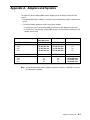
Refer to the appendix HiSpeed WAN Comm. Adapters and Systems to know which
adapter can be installed in which system.
• The whole documentation relative to the HiSpeed WAN Communications is provided in
this present book, except for:
– the hardware installation of the 4Port HiSpeed WAN Comm., 1Port HiSpeed WAN
Comm–B and 1Port WAN Comm Adapter (ISA) adapters which is documented in a
paper documentation provided directly with the hardware.
– the OSI Stack Configuration for X.25 adapters which is detailed in OSI Services
Reference Manual.
• The X.25 documentation which is dispatched in System Management Guide and
Communication Programming Concept refers to another type of X.25 adapter, the X.25
Interface Co-Processor/2.
About this Book
iii
How to Use this Book
This book contains the following chapters:
Introduction
HiSpeed WAN Communications Support Overview.
Chapter 1.
X.25 Introduction is an overview of the X.25 functions and terminology.
Chapter 2.
HiSpeed WAN Comm. Kits is a description of the HiSpeed WAN Comm.
communications support. It lists and describes the mandatory and available
components.
Chapter 3.
HiSpeed WAN Comm. Installation explains how to perform the HiSpeed
WAN Comm. hardware and software installation and how to configure it.
Chapter 4.
HiSpeed WAN Comm. Configurator describes the configuration actions
which may be performed on HiSpeed WAN Communications and lists and
explains all the configuration parameters.
Chapter
HiSpeed WAN Comm. Tools for Problem Solving describes simple
procedures, using the HiSpeed WAN Comm. tools.
5.
Appendix A.
HiSpeed WAN Comm. Adapters and Systems lists for each type of AIX
system the HiSpeed WAN Comm. adapters which can be used.
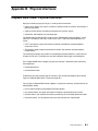
Appendix B.
HiSpeed WAN Comm. Physical Interfaces describes the physical
interfaces available on HiSpeed WAN Comm. adapters and explains how to
recognize which type of interface is implemented on a channel.
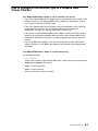
Appendix C.
HiSpeed WAN Comm. Cables gives connector diagrams and pinout
information concerning the attachment cables.
Appendix D.
HiSpeed WAN Comm. Links lists the links which may be implemented
using HiSpeed WAN Comm. communications.
Appendix E.
HiSpeed WAN Comm. Adapter and Port Numbering.
Appendix F.
HiSpeed WAN Comm. Commands are Reference Manual pages
concerning the HiSpeed WAN Comm. commands.
Glossary
Index
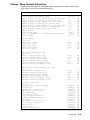
Revision 05 Modifications
Updates include:
• two new (or newly documented) commands: xdconnect and rc.fun.
• one new parameter ’line opening mode’ in ’Change/Show Physical Parameters’.
• improvements in softcopy documentation.
iv
HiSpeed WAN Comm. Installation and Service Guide
Related Publications
• Blue Book, Volume VIII – Fascicle VIII.2 (Melbourne 1988)
CCITT Recommendation X.25 – Interface between data terminal equipment (DTE) and
circuit terminating equipment (DCE) for terminals operating in the packet mode and
connected to public data networks by dedicated circuits.
• ISO 8208 – The International Standard on information processing systems – Data
Communications – X.25 Packet Level Protocol for Data Terminal Equipment (1987).
• ISO 7776 – The International Standard on information processing systems – Data
Communications – High-level Data Link Control procedures – Description of the X.25
LAPB-compatible DTE data link procedures.
• 4Port HiSpeed WAN Comm. Adapter Installation Guide
86 A1 78AT
• 1Port HiSpeed WAN Comm–B Adapter Installation Guide
86 A1 77AT
• 1 Port WAN Comm Adapter (ISA) Installation Guide
86 A1 42AT
• bullx25 Diagnostics Guide
Reference: 86 A2 51AJ
This document describes how to diagnose and solve problems with bullx25 running on
HiSpeed WAN Comm. adapters. It is not delivered with the bullx25 software, but may be
ordered separately.
• XTI/XX25 Administrator and User Guide
Reference: 86 A2 04AP
About this Book
v
vi
HiSpeed WAN Comm. Installation and Service Guide
Table of Contents
Introduction.
HiSpeed WAN Communications Support Overview . . . . . . . . . . . . . . . . . . . . . . . .
1
Chapter 1. X.25 Introduction . . . . . . . . . . . . . . . . . . . . . . . . . . . . . . . . . . . . . . . . . . . .
X.25 Overview . . . . . . . . . . . . . . . . . . . . . . . . . . . . . . . . . . . . . . . . . . . . . . . . . . . . . . . . . . .
X.25 Network: some Basic Information . . . . . . . . . . . . . . . . . . . . . . . . . . . . . . . . . . . . . .
Packet-Switching Network . . . . . . . . . . . . . . . . . . . . . . . . . . . . . . . . . . . . . . . . . . . . . .
DTE and DCE . . . . . . . . . . . . . . . . . . . . . . . . . . . . . . . . . . . . . . . . . . . . . . . . . . . . . . . . .
Network User Address . . . . . . . . . . . . . . . . . . . . . . . . . . . . . . . . . . . . . . . . . . . . . . . . .
Virtual Circuits and Logical Channel Numbers . . . . . . . . . . . . . . . . . . . . . . . . . . . . .
The X.25 Protocol Layers . . . . . . . . . . . . . . . . . . . . . . . . . . . . . . . . . . . . . . . . . . . . . . . . .
X.25 Physical Layer . . . . . . . . . . . . . . . . . . . . . . . . . . . . . . . . . . . . . . . . . . . . . . . . . . . .
X.25 Link Layer . . . . . . . . . . . . . . . . . . . . . . . . . . . . . . . . . . . . . . . . . . . . . . . . . . . . . . .
X.25 Network or Packet Layer . . . . . . . . . . . . . . . . . . . . . . . . . . . . . . . . . . . . . . . . . . .
X.25 Packets Types . . . . . . . . . . . . . . . . . . . . . . . . . . . . . . . . . . . . . . . . . . . . . . . . . . . . . .
Brief Explanation of X.25 Packets . . . . . . . . . . . . . . . . . . . . . . . . . . . . . . . . . . . . . . . .
1-1
1-1
1-1
1-1
1-2
1-3
1-3
1-5
1-5
1-6
1-8
1-9
1-11
Chapter 2. Kits . . . . . . . . . . . . . . . . . . . . . . . . . . . . . . . . . . . . . . . . . . . . . . . . . . . . . . . . .
4Port HiSpeed WAN Comm. Adapter . . . . . . . . . . . . . . . . . . . . . . . . . . . . . . . . . . . . . . .
1Port HiSpeed WAN Comm. Adapter . . . . . . . . . . . . . . . . . . . . . . . . . . . . . . . . . . . . . . .
1Port HiSpeed WAN Comm–B Adapter . . . . . . . . . . . . . . . . . . . . . . . . . . . . . . . . . . . . .
1Port WAN Comm Adapter (ISA) . . . . . . . . . . . . . . . . . . . . . . . . . . . . . . . . . . . . . . . . . . .
2-1
2-2
2-6
2-9
2-12
Chapter 3. Installation . . . . . . . . . . . . . . . . . . . . . . . . . . . . . . . . . . . . . . . . . . . . . . . . . .
HiSpeed WAN Comm. Installation Scenario . . . . . . . . . . . . . . . . . . . . . . . . . . . . . . . . .
Installation Preparation . . . . . . . . . . . . . . . . . . . . . . . . . . . . . . . . . . . . . . . . . . . . . . . . . . .
4Port HiSpeed WAN Comm. Hardware Installation . . . . . . . . . . . . . . . . . . . . . . . . . . .
1Port HiSpeed WAN Comm. Hardware Installation . . . . . . . . . . . . . . . . . . . . . . . . . . .
1Port HiSpeed WAN Comm–B Hardware Installation . . . . . . . . . . . . . . . . . . . . . . . . .
Software Installation . . . . . . . . . . . . . . . . . . . . . . . . . . . . . . . . . . . . . . . . . . . . . . . . . . . . .
System Reconfiguration . . . . . . . . . . . . . . . . . . . . . . . . . . . . . . . . . . . . . . . . . . . . . . . .
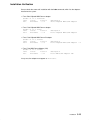
Installation Verification . . . . . . . . . . . . . . . . . . . . . . . . . . . . . . . . . . . . . . . . . . . . . . . . .
Configuration . . . . . . . . . . . . . . . . . . . . . . . . . . . . . . . . . . . . . . . . . . . . . . . . . . . . . . . . . . . .
How to Configure a HiSpeed WAN Comm. Line . . . . . . . . . . . . . . . . . . . . . . . . . . .
How to Configure TCP/IP on HiSpeed WAN Communications . . . . . . . . . . . . . . .
How to Configure OSI Stack on HiSpeed WAN Communications . . . . . . . . . . . . .
How to Configure XPI on HiSpeed WAN Communications . . . . . . . . . . . . . . . . . .
How to Stop and Restart TCP/IP Applications . . . . . . . . . . . . . . . . . . . . . . . . . . . . .
How to Stop and Restart OSI Stack Applications . . . . . . . . . . . . . . . . . . . . . . . . . .
How to Stop and Restart XPI (XX25) Applications . . . . . . . . . . . . . . . . . . . . . . . . .
3-1
3-1
3-1
3-2
3-6
3-9
3-13
3-14
3-15
3-16
3-17
3-18
3-19
3-20
3-21
3-21
3-21
Chapter 4. Configurator . . . . . . . . . . . . . . . . . . . . . . . . . . . . . . . . . . . . . . . . . . . . . . . . .
HiSpeed WAN Comm. Adapter Configurator . . . . . . . . . . . . . . . . . . . . . . . . . . . . . . . . .
HiSpeed WAN Comm. Adapter Configuration Menu . . . . . . . . . . . . . . . . . . . . . . . .
How to List HiSpeed WAN Comm. Adapters . . . . . . . . . . . . . . . . . . . . . . . . . . . . . . . . .
How to Change / Show Characteristics of a HiSpeed WAN Comm. Adapter . . . . .
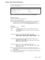
Change / Show Physical Parameters . . . . . . . . . . . . . . . . . . . . . . . . . . . . . . . . . . . . .
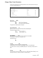
Change / Show Frame Parameters . . . . . . . . . . . . . . . . . . . . . . . . . . . . . . . . . . . . . .
Change / Show Network Parameters . . . . . . . . . . . . . . . . . . . . . . . . . . . . . . . . . . . .
Change / Show Incoming Calls Routing . . . . . . . . . . . . . . . . . . . . . . . . . . . . . . . . . .
4-1
4-2
4-2
4-3
4-4
4-5
4-7
4-9
4-18
Table of Contents
vii
viii
Change / Show Default PVC Parameters . . . . . . . . . . . . . . . . . . . . . . . . . . . . . . . .
Change / Show Specific PVC Parameters . . . . . . . . . . . . . . . . . . . . . . . . . . . . . . . .
Clear Current Configuration . . . . . . . . . . . . . . . . . . . . . . . . . . . . . . . . . . . . . . . . . . . . .
How to Generate Current Configuration for a HiSpeed WAN Comm. Adapter . . . .
How to Load a HiSpeed WAN Comm. Adapter with Last Generated Configuration
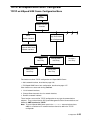
TCP/IP on HiSpeed WAN Comm. Configurator . . . . . . . . . . . . . . . . . . . . . . . . . . . . . .
TCP/IP on HiSpeed WAN Comm. Configuration Menu . . . . . . . . . . . . . . . . . . . . . .
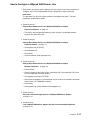
How to Add a HiSpeed WAN Comm. Network Interface . . . . . . . . . . . . . . . . . . . . . . .
How to Manage an IP/HiSpeed WAN Comm. Host . . . . . . . . . . . . . . . . . . . . . . . . . . .
Add an IP/HiSpeed WAN Comm. Host Entry . . . . . . . . . . . . . . . . . . . . . . . . . . . . . .
Change/Show an IP/HiSpeed WAN Comm. Host Entry . . . . . . . . . . . . . . . . . . . . .
Remove an IP/HiSpeed WAN Comm. Host Entry . . . . . . . . . . . . . . . . . . . . . . . . . .
XPI Interface Configurator . . . . . . . . . . . . . . . . . . . . . . . . . . . . . . . . . . . . . . . . . . . . . . . .
XPI Interface Configuration Menu . . . . . . . . . . . . . . . . . . . . . . . . . . . . . . . . . . . . . . . .
How to Manage XPI Network Interface . . . . . . . . . . . . . . . . . . . . . . . . . . . . . . . . . . . . . .
List All XPI Network Interfaces . . . . . . . . . . . . . . . . . . . . . . . . . . . . . . . . . . . . . . . . . .
Add an XPI Network Interface . . . . . . . . . . . . . . . . . . . . . . . . . . . . . . . . . . . . . . . . . . .
Change / Show Characteristics of an XPI Network Interface . . . . . . . . . . . . . . . . .
Remove an XPI Network Interface . . . . . . . . . . . . . . . . . . . . . . . . . . . . . . . . . . . . . . .
How to Manage PVCs on an XPI Network Interface . . . . . . . . . . . . . . . . . . . . . . . . . .
List PVC Assigned to an XPI Network Interface . . . . . . . . . . . . . . . . . . . . . . . . . . . .
Assign a PVC to an XPI Network Interface . . . . . . . . . . . . . . . . . . . . . . . . . . . . . . . .
Remove a PVC . . . . . . . . . . . . . . . . . . . . . . . . . . . . . . . . . . . . . . . . . . . . . . . . . . . . . . .
4-20
4-21
4-22
4-23
4-24
4-25
4-25
4-26
4-27
4-28
4-32
4-32
4-33
4-33
4-34
4-34
4-34
4-35
4-35
4-36
4-36
4-36
4-37
Chapter 5. Tools for Problem Solving . . . . . . . . . . . . . . . . . . . . . . . . . . . . . . . . . . . .
HiSpeed WAN Comm. Maintenance Tools and Problem Solving . . . . . . . . . . . . . . .
Maintenance Tools . . . . . . . . . . . . . . . . . . . . . . . . . . . . . . . . . . . . . . . . . . . . . . . . . . . . . .
Auto-Tests . . . . . . . . . . . . . . . . . . . . . . . . . . . . . . . . . . . . . . . . . . . . . . . . . . . . . . . . . . . .
Loop-Back Tests . . . . . . . . . . . . . . . . . . . . . . . . . . . . . . . . . . . . . . . . . . . . . . . . . . . . . .
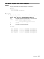
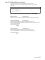
HiSpeed WAN Comm. Error Log Reports . . . . . . . . . . . . . . . . . . . . . . . . . . . . . . . . .
ODM Level Report . . . . . . . . . . . . . . . . . . . . . . . . . . . . . . . . . . . . . . . . . . . . . . . .
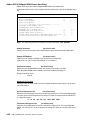
Board Level Report . . . . . . . . . . . . . . . . . . . . . . . . . . . . . . . . . . . . . . . . . . . . . . .
Packet Level Report . . . . . . . . . . . . . . . . . . . . . . . . . . . . . . . . . . . . . . . . . . . . . .
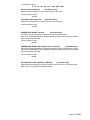
Frame Level Report . . . . . . . . . . . . . . . . . . . . . . . . . . . . . . . . . . . . . . . . . . . . . . .
Physical Level Report . . . . . . . . . . . . . . . . . . . . . . . . . . . . . . . . . . . . . . . . . . . . .
Problem Solving . . . . . . . . . . . . . . . . . . . . . . . . . . . . . . . . . . . . . . . . . . . . . . . . . . . . . . . .
Check Hardware and Software Installation . . . . . . . . . . . . . . . . . . . . . . . . . . . . . . . .
Check Port Status . . . . . . . . . . . . . . . . . . . . . . . . . . . . . . . . . . . . . . . . . . . . . . . . . . . . .
Check Adapter Operating State . . . . . . . . . . . . . . . . . . . . . . . . . . . . . . . . . . . . . . . . .
Check Status of the Physical, Frame and Packet Levels . . . . . . . . . . . . . . . . . . . .
Monitoring of the X.25 Traffic on an Adapter or on a Port . . . . . . . . . . . . . . . . . . .
5-1
5-1
5-1
5-2
5-2
5-3
5-9
5-10
5-11
5-12
5-13
5-14
5-14
5-15
5-15
5-16
5-17
Appendix A. Adapters and Systems . . . . . . . . . . . . . . . . . . . . . . . . . . . . . . . . . . . . .
A-1
Appendix B. Physical Interfaces . . . . . . . . . . . . . . . . . . . . . . . . . . . . . . . . . . . . . . . . .
HiSpeed WAN Comm. Physical Interfaces . . . . . . . . . . . . . . . . . . . . . . . . . . . . . . . . . .
How to Recognize the Interface Type of a HiSpeed WAN Comm. Channel . . . . . .
B-1
B-1
B-3
HiSpeed WAN Comm. Installation and Service Guide
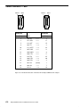
Appendix C. Cables . . . . . . . . . . . . . . . . . . . . . . . . . . . . . . . . . . . . . . . . . . . . . . . . . . . .
HiSpeed WAN Comm. Cable Connector Diagrams and Pin-Out Information . . . . .
Cable CBLG087–1900 . . . . . . . . . . . . . . . . . . . . . . . . . . . . . . . . . . . . . . . . . . . . . . . . . . .
Cable CBLG110–1900 . . . . . . . . . . . . . . . . . . . . . . . . . . . . . . . . . . . . . . . . . . . . . . . . . . . .
Cable VCW 3666 . . . . . . . . . . . . . . . . . . . . . . . . . . . . . . . . . . . . . . . . . . . . . . . . . . . . . . . .
Cable VCW 3657 . . . . . . . . . . . . . . . . . . . . . . . . . . . . . . . . . . . . . . . . . . . . . . . . . . . . . . . .
Cable VCW 3660 . . . . . . . . . . . . . . . . . . . . . . . . . . . . . . . . . . . . . . . . . . . . . . . . . . . . . . . .
Cable CBLG095–1900 . . . . . . . . . . . . . . . . . . . . . . . . . . . . . . . . . . . . . . . . . . . . . . . . . . .
C-1
C-1
C-2
C-3
C-4
C-5
C-6
C-7
Appendix D. Links . . . . . . . . . . . . . . . . . . . . . . . . . . . . . . . . . . . . . . . . . . . . . . . . . . . . . .
HiSpeed WAN Comm. Links . . . . . . . . . . . . . . . . . . . . . . . . . . . . . . . . . . . . . . . . . . . . . . .
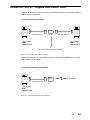
V24/V28 HiSpeed WAN Comm. Links . . . . . . . . . . . . . . . . . . . . . . . . . . . . . . . . . . . . . .
V24/V35 HiSpeed WAN Comm. Links . . . . . . . . . . . . . . . . . . . . . . . . . . . . . . . . . . . . . .
Leased X21–X24/V11 HiSpeed WAN Comm. Links . . . . . . . . . . . . . . . . . . . . . . . . . .
D-1
D-1
D-3
D-5
D-7
Appendix E. Numbering . . . . . . . . . . . . . . . . . . . . . . . . . . . . . . . . . . . . . . . . . . . . . . . .
HiSpeed WAN Comm. Adapter and Port Numbering . . . . . . . . . . . . . . . . . . . . . . . . . .
HiSpeed WAN Comm. Adapter Naming . . . . . . . . . . . . . . . . . . . . . . . . . . . . . . . . . .
HiSpeed WAN Comm. Port Numbering . . . . . . . . . . . . . . . . . . . . . . . . . . . . . . . . . . .
E-1
E-1
E-1
E-2
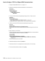
Appendix F. Commands . . . . . . . . . . . . . . . . . . . . . . . . . . . . . . . . . . . . . . . . . . . . . . . . .
arpxd Command . . . . . . . . . . . . . . . . . . . . . . . . . . . . . . . . . . . . . . . . . . . . . . . . . . . . . . . . .
funautotest Command . . . . . . . . . . . . . . . . . . . . . . . . . . . . . . . . . . . . . . . . . . . . . . . . . . . .
funload Command . . . . . . . . . . . . . . . . . . . . . . . . . . . . . . . . . . . . . . . . . . . . . . . . . . . . . . .
funsnap Command . . . . . . . . . . . . . . . . . . . . . . . . . . . . . . . . . . . . . . . . . . . . . . . . . . . . . . .
funstat Command . . . . . . . . . . . . . . . . . . . . . . . . . . . . . . . . . . . . . . . . . . . . . . . . . . . . . . . .
genconf Command . . . . . . . . . . . . . . . . . . . . . . . . . . . . . . . . . . . . . . . . . . . . . . . . . . . . . . .
ifconfigxd Command . . . . . . . . . . . . . . . . . . . . . . . . . . . . . . . . . . . . . . . . . . . . . . . . . . . . .
rc.fun Command . . . . . . . . . . . . . . . . . . . . . . . . . . . . . . . . . . . . . . . . . . . . . . . . . . . . . . . . .
x25dxlate Command . . . . . . . . . . . . . . . . . . . . . . . . . . . . . . . . . . . . . . . . . . . . . . . . . . . . .
x25dstat Command . . . . . . . . . . . . . . . . . . . . . . . . . . . . . . . . . . . . . . . . . . . . . . . . . . . . . .
xdclear Command . . . . . . . . . . . . . . . . . . . . . . . . . . . . . . . . . . . . . . . . . . . . . . . . . . . . . . .
xdconnect Command . . . . . . . . . . . . . . . . . . . . . . . . . . . . . . . . . . . . . . . . . . . . . . . . . . . . .
xdmanage Command . . . . . . . . . . . . . . . . . . . . . . . . . . . . . . . . . . . . . . . . . . . . . . . . . . . .
xdmonitor Command . . . . . . . . . . . . . . . . . . . . . . . . . . . . . . . . . . . . . . . . . . . . . . . . . . . . .
xdping Command . . . . . . . . . . . . . . . . . . . . . . . . . . . . . . . . . . . . . . . . . . . . . . . . . . . . . . . .
F-1
F-2
F-4
F-5
F-6
F-8
F-10
F-11
F-14
F-15
F-18
F-20
F-21
F-23
F-25
F-28
Glossary . . . . . . . . . . . . . . . . . . . . . . . . . . . . . . . . . . . . . . . . . . . . . . . . . . . . . . . . . . . . . . .
Gl–1
Index . . . . . . . . . . . . . . . . . . . . . . . . . . . . . . . . . . . . . . . . . . . . . . . . . . . . . . . . . . . . . . . . . .
X–1
Table of Contents
ix
x
HiSpeed WAN Comm. Installation and Service Guide
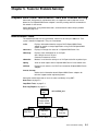
Introduction.
HiSpeed WAN Communications Support Overview
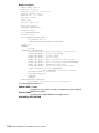
The HiSpeed WAN Communications kits are a family of components which enable
running applications needing a large bandwidth or high performance access to wide area
networks.
A HiSpeed WAN Comm. kit is composed of:
• A multi-channel or mono-channel X.25 adapter.
Each channel is customized with a daughter-board and an associated attachment cable,
providing thus one of the following physical interfaces, V24/V28, V24/V35, leased X21.
• X.25 protocol (link and packet layers) resident on the adapter and software interfaces
which allow different communication stacks to access an X.25 network.
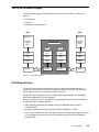
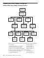
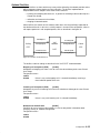
HiSpeed WAN Comm. Software
bullx25
component
Software
HVX
Stack
OSI
Stack
TCP/IP
Configurators
XX25
OSI
Interface
HVX
Interface
Tools
System
TCP/IP
Interface
XPI
Interface
Driver
X.25.3
Adapter
X.25.2
Tests
V24/V28
V24/V35
leased
X21/V11
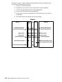
Figure 1. HiSpeed WAN Comm. Software
Introduction
1
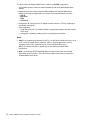
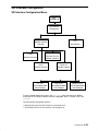
The figure shows the HiSpeed WAN Comm. software (or bullx25) components:
• X.25 protocol and tests which are loaded at bootstrap into the HiSpeed WAN Comm.
adapter.
• Adapter driver which handles communications between the HiSpeed WAN Comm.
adapter micro-code and applications using one of these communications providers:
– TCP/IP,
– OSI stack,
– XX25,
– HVX stack.
• Configurators for setting up the X.25 adapter and the interface (if TCP/IP) according to
the network subscription.
• Tools supplied for:
– using and testing the X.25 network without any application program with direct access
to the driver,
– managing the network by getting statistics and displaying information.
Notes:
1. XX25 (X.25 Programming Interface using XTI) is an API which provides full access to all
X.25.3 services through the XPI interface. XX25 is suited for applications such as
videotext servers and in a general way for servers with direct X.25 access.
XPI (X.25 Provider Interface) is specified by the OSI Working Group of UNIX
International.
2. HVX is an emulation of GCOS6/HVS6 software on AIX, which allows to run DPS6
applications on AIX systems. The HVX communications stack accesses directly the
HiSpeed WAN Comm. driver.
2
HiSpeed WAN Comm. Installation and Service Guide
Chapter 1. X.25 Introduction
X.25 Overview
The X.25 protocol was first defined at the end of the seventies by CCITT Recommendation
X.25. Further revisions of the recommendation were published in 1984 and 1988. The
International Organization for Standardization (ISO) has also published the X.25
recommendations as ISO 8208 and ISO 7776.
The X.25 protocol is designed to manage communications on a wide area network (WAN).
Such a network can interconnect intelligent switching nodes and transmit messages divided
into parts (called packets) over circuits which are used by many network users.
This chapter is an introduction to the X.25 functionality. It provides:
• some basic information and terminology on an X.25 network, on page 1-1,
• a description of the X.25 protocol layers, on page 1-5,
• a list of X.25 packets, on page 1-9.
X.25 Network: some Basic Information
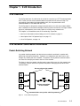
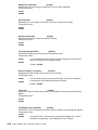
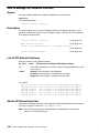
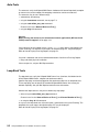
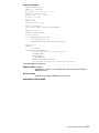
Packet-Switching Network
In a packet-switching network, the data to be transmitted is combined in a packet with
addressing and control information. A packet is an independent unit which can be sent
through any suitable path in the network. The packets of many different communications
can share the same physical routes and lines in the network.
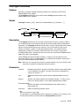
The figure 2 shows how packet switching makes more efficient use of a high-speed circuit.
The triangles, squares and circles represent the packets belonging to each of the three
communications.
Access points to the network
Packets transmitted
on the network
3 communications on a packet–switching network
Figure 2. Packet-Switching Network
X.25 Introduction
1-1
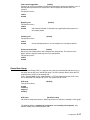
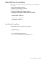
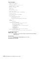
DTE and DCE
Two types of equipment are used on an X.25 network:
• DTE (Data Terminal Equipment) is an equipment which uses the network for
communications. A process on this DTE has to communicate with another process
running on another equipment.
• DCE (Data Circuit-Terminating Equipment) is an equipment which provides access to the
network, that is establishes, maintains and ends the connections.
Every DTE must have an associated DCE.
DTE and DCE are functional definitions, they do not correspond to specific items of
equipment.
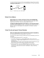
In a public network, a DTE is a user equipment which has information to communicate with
another DTE, whereas a DCE is an equipment which provides DTEs with access to the
network. See the figure 3.
X.25 Line
DTE
DCE
DCE
X.25 Network
X.25 Line
DCE
X.25 Line
DTE
DTE
Figure 3. X.25 Public Network : DTEs and DCEs
1-2
HiSpeed WAN Comm. Installation and Service Guide
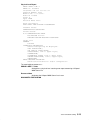
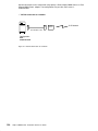
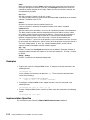
In a direct connection through an X.25 line, the two equipments located at each end of the
connection must apply the following rule: one must be declared as DTE type and the other
as DCE type. See the figure 4.
X.25 Line
DTE
DCE
Figure 4. X.25 Direct Connection : DTE and DCE
Network User Address
Each X.25 line in an X.25 network is identified by a number called the Network User
Address (NUA) which is assigned by the network provider of the X.25 line subscription.
While most public networks use the X.121 addressing standard to create NUAs, private
networks may use their own schemes for assigning addresses to lines.
Under the X.121 addressing standard, the NUA comprises a 3-digit country code, followed
by a National Terminal Number (NTN) up to 12 digits long. This 15-digit code uniquely
identifies the X.25 line throughout the world. If the network provider allocates fewer than 12
digits to the NTN, the remaining digits can be allocated as a sub-address, to identify
individual users.
Virtual Circuits and Logical Channel Numbers
When a user (process) wants to communicate with another user over the X.25 network, a
logical path or virtual circuit has to be assigned to this communication. All the packets of
this communication will be transmitted through this virtual circuit.
For each DTE, the number of maximum needed virtual circuits are defined by the X.25 line
subscription.
The communication between two DTEs is established:
• on each DTE, making active an available virtual circuit in order to connect to its
associated DCE. A logical channel number identifies this connection and is included in
each packet sent.
The two logical channel numbers (one for calling DTE, the other for called DTE) may be
different. Each DTE only needs to know its own logical channel number.
• between the two DCEs, reserving a virtual circuit for this communication.
At configuration, each virtual circuit is either for outgoing calls only, incoming calls only,
or two-way calls, but once the virtual circuit is established it is always for two-way
communication.
X.25 Introduction
1-3
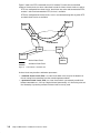
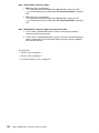
Figure 5 shows four DTEs connected to an X.25 network. For each of them a defined
number of virtual circuits has been subscribed, but not all of these virtual circuits are active.
DTE1 has configured four virtual circuits, two of them are active and connected to DTE2,
another is active and connected to DTE3, the last is available.
DTE4 has configured two virtual circuits, but it is not communicating with any other DTE
and both virtual circuits are available.
DTE 2
DTE 1
DCE
DCE
DCE
X.25 Network
DCE
DCE
DCE
DTE 3
Active Virtual Circuit
DTE 4
Available Virtual Circuit
Figure 5. X.25 Network : Virtual Circuits
A virtual circuit may be either switched or permanent:
• a switched virtual circuit (SVC) is a virtual circuit which exists only for the duration of
the call, acting like a connection over the normal telephone network,
• a permanent virtual circuit (PVC) is a virtual circuit which is permanently established
between two addresses; it ties up a logical channel permanently. It is like having a leased
line. Nowadays in practice, permanent virtual circuits are rarely used.
1-4
HiSpeed WAN Comm. Installation and Service Guide
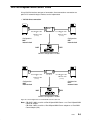
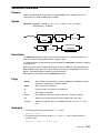
The X.25 Protocol Layers
The X.25 protocol comprises the three lowest layers of the OSI model, as shown in the
figure 6:
• physical layer,
• link layer,
• network layer or packet layer.
DTE
DTE
Applications
Applications
including
highest
layers
including
highest
layers
X.25 Network
DCE
DCE
Packet
Layer
Packet
Layer
Packet
Layer
Packet
Layer
Link
Layer
Link
Layer
Link
Layer
Link
Layer
Physical
Layer
Physical
Layer
Physical
Layer
Physical
Layer
Modem
Modem
Modem
Modem
X.25 Line
X.25 Line
Figure 6. X.25 Protocol layers
X.25 Physical Layer
The physical layer handles the mechanical, electrical and functional characteristics to
access and transmit the bit stream over the physical medium. It activates, maintains and
de-activates the physical circuit between a DTE and a DCE.
The physical layers implemented on the HiSpeed WAN Comm. adapters are completely
described in Appendix B. Physical Interfaces.
As the X.25 transmissions are synchronous, the clock signals have to be transmitted with
the data and may have different origins:
• either external, provided by the network or the peer equipment (local modem or
associated DCE)
• or internal, generated by the physical layer when the equipment is a DCE.
• In the case of a private link, the clock signals may be generated by both equipments, that
is, each equipment generates its transmission clock and receives the corresponding
reception clock.
X.25 Introduction
1-5
X.25 Link Layer
The link layer is responsible for the reliable transfer of blocks of data across the physical
layer. It provides error detection, flow control and sequencing of blocks of data provided by,
and delivered to, the network layer.
The link layer uses a link access procedure to ensure that data and control information are
accurately exchanged over the physical circuit between the DTE and DCE. The
characteristics of this layer are based on High-level Data Link Control (HDLC), and more
precisely on the Link Access Procedure Balanced (LAPB).
LAPB is a synchronous and full-duplex procedure. Once a link is started, either station can
transfer information on its own initiative without waiting for permission from the other. It
includes recovery functions.
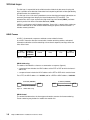
HDLC Frames
In HDLC, all commands, responses and data are transmitted in frames.
In an HDLC frame the data are inserted after a header containing address and control
information and before a trailer containing a frame-check sequence; two flags define the
limits of the frame.
Flag
01111110
Address
11000000
10000000
Control
Data
FCS
Flag
01111110
Figure 7. HDLC Frame
HDLC Addressing
The address field identifies a frame as a command or a response (figure 8):
• a command frame includes the HDLC address of the DTE or DCE to which the frame is
addressed,
• a response frame includes the HDLC address of the DTE or DCE which sent the frame.
For a DTE, the HDLC address is 11000000; and for a DCE the HDLC address, 10000000.
Command (11000000)
Command (10000000)
DCE
DTE
Response (10000000)
DTE
DCE
Response (11000000)
Figure 8. HDLC Addressing
HDLC Control
The control field determines the frame type and contains counters for frame numbering.
Frame numbering may be done in modulo 8 or modulo 128.
1-6
HiSpeed WAN Comm. Installation and Service Guide
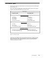
HDLC Frame Types
There are three types of frames:
Format
Commands
Information
I
Supervisory
RR Receive Ready
RNR Receive Not Ready
REJ Reject
Unnumbered
SABM
Set Asynchronous Balanced Mode
Responses
RR Receive Ready
RNR Receive Not Ready
REJ Reject
DISC Disconnect
DM Disconnect Mode
UA Unnumbered Acknowledge
FRMR Frame Reject
Figure 9. HDLC Frame Types
Information frames
I
Information frame transfers user data.
Supervisory frames
RR
Receive Ready frame, sent by a receiver in order to acknowledge I frame
reception when this receiver has no I frame to send.
RNR
Receive Not Ready frame, sent by a receiver in order to stop transmission.
RNR acknowledges the frames received earlier.
REJ
Reject frame requests a new transmission of frames, numbers of which are
subsequent to a specified number. REJ acknowledges the frames
received earlier.
As for the Information frames, the Supervisory frames are numbered sequentially.
Unnumbered frames
SABM
Set Asynchronous Balanced Mode frame, indicates to the receiver that it
may transmit data without asking for permission.
DISC
Disconnect frame ends the link connection.
DM
Disconnect Mode frame indicates that the station is disconnected.
UA
Unnumbered Acknowledge frame acknowledges an unnumbered
command, for instance SABM.
FRMR
Frame Reject frame indicates the reason why a frame has been rejected by
the receiver.
X.25 Introduction
1-7
X.25 Network or Packet Layer
The packet layer manages the establishment, maintenance and termination (routing) of
connections while providing the upper layer with independence from the data transmission
and switching functions used to connect systems.
The packet layer protocol specifies how virtual circuits between DTEs are established,
maintained and cleared. This layer defines:
– the way a single physical channel (physical and link layers) can be treated as a set of
multiple logical channels, each of them providing a virtual circuit,
– the structure of data packets, and of the control packets used to establish and
manage a virtual circuit between two DTEs.
A packet is a unit of information transmitted from one DTE to another DTE through the
network. It comprises a sequence of data and control elements in a special format which is
always transmitted as a whole. The default packet size is defined by subscription.
The recommendations for the packet layer are not so specific as those for the physical and
link layers. Network providers have some freedom in implementing the packet functions.
1-8
HiSpeed WAN Comm. Installation and Service Guide
X.25 Packets Types
Different types of packet are used for making a call and accepting a call, transferring data
and terminating a call.
Here is the list of the X.25 packet types; some of them are DTE specific or DCE specific,
the others may be generated either by a DTE or by a DCE.
Packet Type
From DCE to DTE
From DTE to DCE
Call Set-Up and Clearing
Call-Request
Call-Accepted
Clear-Request
Incoming-Call
Call-Connected
Clear-Indication
DCE Clear-Confirmation
DTE Clear-Confirmation
Data and Interrupt
DTE Data
DTE Interrupt
DTE Interrupt-Confirmation
DCE Data
DCE Interrupt
DCE Interrupt-Confirmation
Flow Control and Reset
DTE Receive Ready (RR)
DTE Receive Not Ready (RNR)
DCE Receive Ready (RR)
DCE Receive Not Ready (RNR)
Figure 10. X.25 Packets Types
In some cases, the contents and even the type of the packet when it reaches the called
DTE are different from when it left the calling DTE. This is because some information is
different for each DTE (for example logical channel number), or some information is
inserted or modified by the network.
X.25 Introduction
1-9
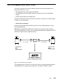
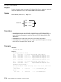
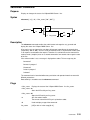
The figure 11 shows a simple example of transferred packets during a call between two
DTEs using a switched virtual circuit (SVC):
1. A makes a call, which B receives.
2. B accepts the call; A receives a call saying the call has been connected.
3. A sends some data, but does not ask for acknowledgment.
4. A sends some more data, which B acknowledges.
5. A clears the call; B receives indication of this and confirms that is has received
the indication.
6. The network confirms to A that the call has been cleared.
Network
DTE A
DCE
DCE
Call-Request packet
DTE B
Incoming-Call packet
Call-Connected packet
1
2
Call-Accepted packet
Data packet
3
Data packet
Data packet
Acknowledgement
4
Data packet
Acknowledgement
Clear-Request packet
Clear-Indication packet
5
Clear-Confirmation packet
Clear-Confirmation packet
6
Figure 11. Sequence of packets in an example call over a switched virtual circuit
1-10
HiSpeed WAN Comm. Installation and Service Guide
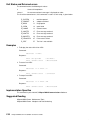
Brief Explanation of X.25 Packets
Call Set-Up and Clearing Packets
Call-Request
Packet transmitted by a DTE to ask that a connection for a call be
established throughout the network.
Incoming-Call
Packet transmitted by a DCE to inform a DTE that another DTE has
requested a call.
Call-Accepted
Packet transmitted by a called DTE to indicate to the DCE that it
accepts the incoming call.
Call-Connected
Packet transmitted by a DCE to inform a calling DTE that the
connection for the call has been completely established.
Clear-Request
Packet transmitted by a DTE to ask that a call be cleared.
Clear-Indication
Packet transmitted by a DCE to inform a DTE that a call has been
cleared.
Clear-Confirmation Packet transmitted either by a DCE or a DTE to confirm that a call
has been cleared.
Data and Interrupt Packets
These three packet types may be transmitted either by a DTE or by a DCE.
Data
Packet to transmit user data over a virtual circuit.
Interrupt
Packet to overtake normal data packets (which are delivered in
sequence).
Interrupt-Confirmation Packet used to acknowledge the receipt of an interrupt packet.
Flow Control and Reset Packets
Receive-Ready
Packet transmitted by a DTE or a DCE to indicate the ability to
receive a defined number of data packets.
Receive-Not-Ready Packet transmitted by a DTE or a DCE to indicate a temporary
inability to receive additional data packets on a given virtual circuit.
Reset-Request
Packet transmitted by a DTE for resetting a virtual circuit at the
DTE/DCE interface.
Reset-Indication
Packet transmitted by a DCE to indicate to a DTE that a reset-request
packet has been received.
Reset-Confirmation Packet transmitted either by a DCE or a DTE to confirm that a reset
operation has been cleared.
X.25 Introduction
1-11
Restart Packets
Restart-Request
Packet transmitted by a DTE to request that a link be restarted.
Restart-Indication
Packet transmitted by a DCE to indicate to a DTE that a restart-request
packet has been received.
Restart-Confirmation
Packet transmitted either by a DCE or a DTE to confirm that the link has
been restarted.
Diagnostic Packets
Diagnostic
1-12
Packet used by a DCE to indicate errors conditions which cannot be
indicated by usual indication packets.
HiSpeed WAN Comm. Installation and Service Guide
Chapter 2. Kits
The HiSpeed WAN Comm. communications kits have some common characteristics:
– X.25 protocol (including X.25.3) resident on the adapter,
– interface with different communications providers, TCP/IP, OSI, XX25 and HVX,
– software conformity with the ISO 8882 standard and the X.25–84 and X.25–88 CCITT
recommendations,
– hardware and software conformity with NET2 conformity tests.
This chapter describes the specific characteristics of the adapters:
• 4Port HiSpeed WAN Comm., on page 2-2,
• 1Port HiSpeed WAN Comm., on page 2-6,
• 1Port HiSpeed WAN Comm–B, on page 2-9,
• 1Port WAN Comm Adapter (ISA), on page 2-12.
HiSpeed WAN Comm. Kits
2-1
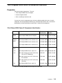
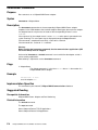
4Port HiSpeed WAN Comm. Adapter
Characteristics
The 4Port HiSpeed WAN Comm. adapter provides four X.25 channels. The four channels
together support a maximum of 1024 virtual circuits (SVC or PVC) with a total data
transfer rate of 2Mbps. Packet size is up to 4096 bytes.
The four channels can be configured independently, which provides flexibility and
modularity.
Three types of physical interfaces are available :
• V24/V28, up to 19.2 Kbps,
• V24/V35, up to 64 Kbps,
• Leased X21–X24/V11, up to 2 Mbps.
The V24/V28, V24/V35 and leased X21–X24/V11 interfaces may be implemented on any of
the four channels.
Refer to:
• Physical Interfaces, on page B-1, to get more information about interface description.
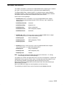
Hardware Components
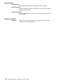
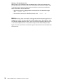
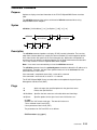
The figure 12 shows the four items included in the 4Port HiSpeed WAN Comm. hardware:
• 4Port HiSpeed WAN Comm. board,
• interface daughter-boards,
• distribution box,
• cables, for connection to the X.25 networks.
2-2
HiSpeed WAN Comm. Installation and Service Guide
78-pin Connector
4Port HiSpeed
WAN Comm.
Adapter
ZILOG
IUSC
20MHz
1
RAM
4Mb
2
0
3
MCA Bus
Interface Daughter–Boards
V24
4 max
V35
4 max
V11
4 max
ASIC
LSI LOGIC
LR33000
25MHz
25-pin System End Connectors
3
2
1
Distribution Box
0
Attachment Cables
Cable V24 (device end 25 position)
Cable V35 (device end 34 position)
Cable leased X21 (device end 15 position)
max. 2 Mbps
max. 64 Kbps
max. 19,2 Kbps
Figure 12. 4Port HiSpeed WAN Comm. Hardware Components
HiSpeed WAN Comm. Kits
2-3
Board
The 4Port HiSpeed WAN Comm. board occupies one slot on the MCA bus of the system.
It is based on:
• a RISC 32-bit processor (LSI LOGIC LR33000, 25MHz) with a 4-Mbyte RAM,
• an ASIC (Application-Specific Integrated Circuit) for dispatch of the four channels,
• an HDLC communication controller (ZILOG IUSC 20MHz) per channel,
• a 78-pin connector which plugs in at the rear panel of the system.
Interface Daughter-Boards
For each channel the physical interface is defined by both a daughter-board and the
associated attachment cable. The daughter-board(s) is(are) plugged onto the 4Port
HiSpeed WAN Comm. board at the emplacement(s) corresponding to the channel(s) to be
used. There are three types of interface daughter-board:
• V24 daughter-board for implementation of V24/V28 interface,
• V35 daughter-board for implementation of V24/V35 interface,
• V11 daughter-board for implementation of leased X21/V11 interface.
Distribution Box
The distribution box picks up all the signals concerning the four X.25 channels on the 78-pin
connector of the 4Port HiSpeed WAN Comm. board and dispatches them 3 meters further,
on four 25-pin connectors, one for each channel.
Cables
For each channel, the attachment cable plugs in the distribution box in the 25-pin connector
of the corresponding channel. The cable to be used depends on the interface
daughter-board installed on this channel and on some other specifications.
Refer to 4Port HiSpeed WAN Comm. Adapter Installation Guide provided with the 4Port
HiSpeed WAN Comm. hardware to have the complete list of cables.
2-4
HiSpeed WAN Comm. Installation and Service Guide
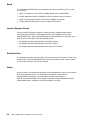
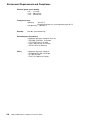
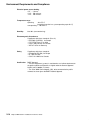
Environment Requirements and Compliance
Electrical power source loading
+5V : 2 A max.
+12V : 400 mA max.
–12V : 400 mA max.
Temperature range
operating
: 0 to 55 °C
(permitting insertion in a system operating up to 40 °C)
non-operating : –40 to 85 °C
Humidity
0 to 90% (non-condensing)
Electromagnetic disturbances
Compliance with these standards (Class A)
– EN 55022 (CISPR22) for Europe
– FCC CFR47 Part 15 for USA
– CSA C.108.8 M1983 for Canada
– VDE 871 6/78 for Germany
Safety
Compliance with these standards
– EN 60 950 (IEC 950) for Europe
– UL 1950 for USA
– CSA C.22.2.N950 for Canada
Certification
BABT Approval
– The host equipment (system) is considered as an indirect attachment to
the public network and therefore is eligible under the General Approval
NS/G/12345/J/100003 (7/1/1993).
– The 4Port HiSpeed WAN Comm. adapter, to be connected to the public
network, has been given the BABT National Approval.
HiSpeed WAN Comm. Kits
2-5
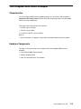
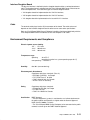
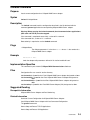
1Port HiSpeed WAN Comm. Adapter
Characteristics
The 1Port HiSpeed WAN Comm. adapter provides an X.25 channel, which supports a
maximum of 256 virtual circuits (SVC or PVC) with a total data transfer rate of 128 Kbps.
Packet size is up to 4096 bytes.
Three types of 1Port HiSpeed WAN Comm. adapters are available :
• 1Port HiSpeed WAN Comm. adapter – V24, which implements V24/V28 physical
interface, up to 19.2 Kbps,
• 1Port HiSpeed WAN Comm. adapter – V35, which implements V24/V35 physical
interface, up to 64 Kbps,
• 1Port HiSpeed WAN Comm. adapter – V11, which implements Leased X21–X24/V11
physical interface, up to 128 Kbps,
Refer to:
• Physical Interfaces, on page B-1, to get more information about interface description.
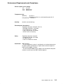
Hardware Components
The 1Port HiSpeed WAN Comm. hardware is composed of these items:
• 1Port HiSpeed WAN Comm. board,
• cables, for connection to the X.25 networks.
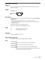
Board
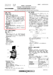
The 1Port HiSpeed WAN Comm. board (figure 13) occupies one slot on the MCA bus of the
system. It uses:
80186
ASIC
85C30
interface
chips
25–pin
connector
Figure 13. 1Port HiSpeed WAN Comm. Board
2-6
HiSpeed WAN Comm. Installation and Service Guide
The 1Port HiSpeed WAN Comm. adapter is based on:
• an INTEL 80C186 processor with a 1-Mbyte RAM,
• an ASIC (Application-Specific Integrated Circuit) for managing the CPU and
Communication Controller accesses,
• a Multiprotocol Serial Communication Controller (SCC – 85C30, 7,68 MHz),
• interface chips specific to one of the three interfaces: V24/V28, V24/V35 or leased
X21–X24/V11,
• a 25-pin connector which plugs in at the rear panel of the system.
The physical interface is defined by both the interface chips and the associated attachment
cable.
Cables
The cables to be used depend on the type of the physical interface and on some other
specifications.
• 1Port HiSpeed WAN Comm.–V24 cable,
V24 attachment cable
V24 adapter
Figure 14. 1Port HiSpeed WAN Comm.–V24 Board
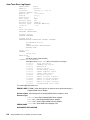
• 1Port HiSpeed WAN Comm.–V35 cables,
V35 adapter
V35
adapter
cable
V35 attachment cable
Figure 15. 1Port HiSpeed WAN Comm.–V35 Board
• 1Port HiSpeed WAN Comm.–V11 cables,
V11 adapter
V11
adapter
cable
V11 attachment cable
Figure 16. 1Port HiSpeed WAN Comm.–V11 Board
Refer to 1Port HiSpeed WAN Comm. Components Identification, on page 3-6, to have the
complete list of cables.
HiSpeed WAN Comm. Kits
2-7
Environment Requirements and Compliance
Electrical power source loading
+5V : 1.3 A max.
+12V : 100 mA max.
–12V : 100 mA max.
Temperature range
operating
: 0 to 55 °C
(permitting insertion in a system operating up to 40 °C)
non-operating : –40 to 85 °C
Humidity
0 to 90% (non-condensing)
Electromagnetic disturbances
Compliance with these standards (Class A)
– EN 55022 (CISPR22) for Europe
– FCC CFR47 Part 15 for USA
– CSA C.108.8 M1983 for Canada
– VDE 871 6/78 for Germany
Safety
2-8
Compliance with these standards
– EN 60 950 (IEC 950) for Europe
– UL 1950 for USA
– CSA C.22.2.N950 for Canada
HiSpeed WAN Comm. Installation and Service Guide
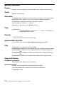
1Port HiSpeed WAN Comm–B Adapter
Characteristics
The 1Port HiSpeed WAN Comm–B adapter provides an X.25 channel, which supports a
maximum of 256 virtual circuits (SVC or PVC) with a total data transfer rate of 128Kbps.
Packet size is up to 4096 bytes.
Three types of physical interfaces are available:
• V24/V28, up to 19.2 Kbps,
• V24/V35, up to 64 Kbps,
• Leased X21–X24/V11, up to 128 Kbps,
Refer to:
• Physical Interfaces, on page B-1, to get more information about interface description.
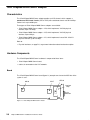
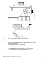
Hardware Components
The figure 17 shows the three items included in the 1Port HiSpeed WAN Comm–B
hardware:
• 1Port HiSpeed WAN Comm–B board,
• interface daughter-board,
• cable, for connection to the X.25 network.
HiSpeed WAN Comm. Kits
2-9
1Port HiSpeed
WAN Comm–B
Adapter
85C30
ASIC
80186
25–pin
connector
Interface Daughter–Board
V24
V35
V11
Attachment Cable
Cable V24 (device end 25 position)
Cable V35 (device end 34 position)
Cable leased X21 (device end 15 position)
max. 128 Kbps
max. 64 Kbps
max. 19,2 Kbps
Figure 17. 1Port HiSpeed WAN Comm–B Hardware Components
Board
The 1Port HiSpeed WAN Comm–B board is an adapter which occupies one slot on the
MCA bus of the system. It uses:
• an INTEL 80C186 processor with a 1-Mbyte RAM,
• an ASIC (Application-Specific Integrated Circuit) for managing the CPU and
Communication Controller accesses,
• a Multiprotocol Serial Communication Controller (SCC – 85C30, 7,68 MHz),
• a 25-pin connector which plugs in at the rear panel of the system.
2-10
HiSpeed WAN Comm. Installation and Service Guide
Interface Daughter-Board
The physical interface is defined by both a daughter-board and the associated attachment
cable. The daughter-board is plugged onto the 1Port HiSpeed WAN Comm–B board at the
reserved emplacement. There are three types of interface daughter-board:
• V24 daughter-board for implementation of a V24/V28 interface,
• V35 daughter-board for implementation of a V24/V35 interface,
• V11 daughter-board for implementation of a leased X21/V11 interface.
Cable
The terminal cable plugs into the 25-pin connector of the board. The cable to be used
depends on the interface daughter-board installed and on some other specifications.
Refer to 1Port HiSpeed WAN Comm–B Adapter Installation Guide provided directly with the
1Port HiSpeed WAN Comm–B hardware to have the complete list of cables.
Environment Requirements and Compliance
Electrical power source loading
+5V : 1.5 A max.
+12V : 100 mA max.
–12V : 100 mA max.
Temperature range
operating
: 0 to 55 °C
(permitting insertion in a system operating up to 40 °C)
non-operating : –40 to 85 °C
Humidity
0 to 90% (non-condensing)
Electromagnetic disturbances
Compliance with these standards (Class A)
– EN 55022 (CISPR22) for Europe
– FCC CFR47 Part 15 for USA
– CSA C.108.8 M1983 for Canada
– VDE 871 6/78 for Germany
Safety
Compliance with these standards
– EN 60 950 (IEC 950) for Europe
– UL 1950 for USA
– CSA C.22.2.N950 for Canada
Certification
BABT Approval
– The host equipment (system) is considered as an indirect attachment to
the public network and therefore is eligible under the General Approval
NS/G/12345/J/100003 (7/1/1993).
– The 1Port HiSpeed WAN Comm–B adapter, to be connected to the public
network, has been given the BABT National Approval.
HiSpeed WAN Comm. Kits
2-11
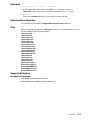
1Port WAN Comm Adapter (ISA)
Characteristics
The 1Port WAN Comm Adapter (ISA) adapter provides an X.25 channel, which supports a
maximum of 256 virtual circuits (SVC or PVC) with a total data transfer rate of 128 Kbps.
Packet size is up to 4096 bytes.
Three types of 1Port WAN Comm Adapter (ISA) are available:
• 1Port WAN Comm Adapter (ISA) – V24, which implements V24/V28 physical interface,
up to 19.2 Kbps,
• 1Port WAN Comm Adapter (ISA) – V35, which implements V24/V35 physical interface,
up to 64 Kbps,
• 1Port WAN Comm Adapter (ISA) – V11, which implements Leased X21–X24/V11
physical interface, up to 128 Kbps,
Refer to:
• Physical Interfaces, on page B-1, to get more information about interface description.
Hardware Components
The 1Port WAN Comm Adapter (ISA) hardware is composed of these items:
• 1Port WAN Comm Adapter (ISA) board,
• cables, for connection to the X.25 networks.
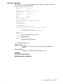
Board
The 1Port WAN Comm Adapter (ISA) board (figure 18) occupies one slot on the ISA bus of
the system.
RAM
interface
chips or
daughter-board
85C30
80C186
ASIC
jumpers
Figure 18. 1Port WAN Comm Adapter (ISA) Board
2-12
HiSpeed WAN Comm. Installation and Service Guide
25–pin
connector
The 1Port WAN Comm Adapter (ISA) is based on:
• an INTEL 80C186 processor with a 1-Mbyte RAM,
• an ASIC (Application-Specific Integrated Circuit) for managing the CPU and
Communication Controller accesses,
• a Multiprotocol Serial Communication Controller (SCC – 85C30, 7,68 MHz),
• interface chips specific to one of the three interfaces: V24/V28, V24/V35 or leased
X21–X24/V11,
• a 25-pin connector.
The physical interface is defined by both the interface chips and the associated attachment
cable.
Cables
The cables to be used depend on the type of the physical interface and on some other
specifications.
• 1Port WAN Comm Adapter (ISA)–V24 cable,
V24 adapter
V24 attachment cable
Figure 19. 1Port WAN Comm Adapter (ISA)–V24
• 1Port WAN Comm Adapter (ISA)–V35 cables,
V35 adapter
V35
adapter
cable
V35 attachment cable
Figure 20. 1Port WAN Comm Adapter (ISA)–V35
• 1Port WAN Comm Adapter (ISA)–V11 cables,
V35 adapter
V11
adapter
cable
V11 attachment cable
Figure 21. 1Port WAN Comm Adapter (ISA)–V11
Refer to 1 Port WAN Comm Adapter (ISA) Installation Guide provided directly with the
1Port WAN Comm Adapter (ISA) hardware to have the complete list of cables.
HiSpeed WAN Comm. Kits
2-13
Environment Requirements and Compliance
Electrical power source loading
+5V : 2 A max.
+12V : 150 mA max.
–12V : 150 mA max.
Temperature range
operating
: 0 to 55 °C
(permitting insertion in a system operating up to 40 °C)
non-operating : –40 to 85 °C
Humidity
0 to 90% (non-condensing)
Electromagnetic disturbances
Compliance with these standards (Class A)
– EN 55022 (CISPR22) for Europe
– FCC CFR47 Part 15 for USA
– CSA C.108.8 M1983 for Canada
– VDE 871 6/78 for Germany
2-14
Safety
Compliance with these standards
– EN 60 950 (IEC 950) for Europe
– UL 1950 for USA
– CSA C.22.2.N950 for Canada
Certification
BABT Approval
– The host equipment (system) is considered as an indirect attachment to
the public network and therefore is eligible under the General Approval
NS/G/12345/J/100003 (7/1/1993).
– The 1Port WAN Comm Adapter (ISA), to be connected to the public
network, has been given the BABT National Approval.
HiSpeed WAN Comm. Installation and Service Guide
Chapter 3. Installation
HiSpeed WAN Comm. Installation Scenario
Here are the list of the sequential tasks to be performed for a correct installation of an
HiSpeed WAN Communications kit:
• Installation preparation, on page 3-1, is common to all HiSpeed WAN Comm. adapter
types.
• Hardware installation, is specific to each adapter type:
– 4Port HiSpeed WAN Comm. hardware installation is described in 4Port HiSpeed WAN
Comm. Adapter Installation Guide provided directly with the 4Port HiSpeed WAN
Comm. hardware.
It is also described in 4Port HiSpeed WAN Comm. hardware installation, on page 3-2.
– 1Port HiSpeed WAN Comm. hardware installation, on page 3-6.
– 1Port HiSpeed WAN Comm–B hardware installation is described in 1Port HiSpeed
WAN Comm–B Adapter Installation Guide provided directly with the 1Port HiSpeed
WAN Comm–B hardware.
It is also described in 1Port HiSpeed WAN Comm–B hardware installation, on page
3-9.
– 1Port WAN Comm Adapter (ISA) hardware installation is described in 1 Port WAN
Comm Adapter (ISA) Installation Guide provided directly with the 1Port WAN Comm
Adapter (ISA) hardware.
• Software installation, on page 3-13, is common to all HiSpeed WAN Comm. adapter
types and has to be performed only once after the first hardware installation
• Configuration, on page 3-16, is common to all HiSpeed WAN Comm. adapter types and
has to be performed for each new channel installed.
After completion of each task, when it is possible and significant, a simple test is described
in order to verify if this task has been correctly fulfilled.
Installation Preparation
• Subscribe to an X.25 line (or more) from your network provider if you have to connect
your system on a public network.
(Refer to Chapter 4. Adapter Configuration to get information about X.25 parameters).
• Check in the SRB (Software Release Bulletin) provided with the bullx25 HiSpeed WAN
Communications Software, that your system conforms to the hardware requirements
(disk and memory space).
• Refer to the Installation Guide specific to your system if you are not familiar with
hardware and software installation.
• Define in which MCA slot(s) to install the 4Port HiSpeed WAN Comm., 1Port HiSpeed
WAN Comm. or 1Port HiSpeed WAN Comm–B adapter(s).
Refer to 1 Port WAN Comm Adapter (ISA) Installation Guide for a 1Port WAN Comm
Adapter (ISA).
Note: A 4Port HiSpeed WAN Comm. adapter cannot be installed in a DPX/20 1xx system
for mechanical limitations.
Installation
3-1
4Port HiSpeed WAN Comm. Hardware Installation
Preparation
Verify the hardware components. They are:
• 4Port HiSpeed WAN Comm. board,
• Interface daughter-boards,
• Distribution box,
• Cables, according to interfaces used.
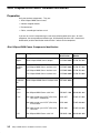
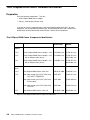
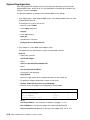
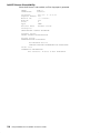
If you are not sure of a component type, refer to the following table which gives, for each
component, the correspondence between type, MI (Marketing Identifier, that is commercial
identification) and the Identification number which is written on the component.
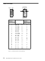
4Port HiSpeed WAN Comm. Components Identification
Component
Designation
MI
Identification
Adapter
4Port HiSpeed WAN Comm. adapter
DCCG044–0000 76 706 766–002
Daughter–
Boards
V24 HiSpeed WAN Comm. interface card
DCCG047–0000 76 706 767–001
V35 HiSpeed WAN Comm. interface card
DCCG045–0000 76 706 768–001
V11 HiSpeed WAN Comm. interface card
DCCG046–0000 76 706 769–002
4Port HiSpeed WAN Comm. interface cable
CKTG043–0000
– V24
10m HiSpeed WAN Comm. cable V24
CBLG087–1900
90 246 001–001
– V35
10m cable remote sync V35/IF (25m/34m)
ISO std PTT/TRANSPAC
VCW 3657
76 958 153–001
10m cable remote sync V35/IF (25m/34m)
EIA standard
VCW 3660
76 958 300–001
10m cable remote sync V35/IF (25m/34m)
ISO 2593
VCW 3666
76 958 248–001
10m HiSpeed WAN Comm. cable V11
CBLG095–1900
90 166 001–002
Distribution
Box
Identification
Number
Cables:
– V11
Figure 22. 4Port HiSpeed WAN Comm. Components Identification
3-2
HiSpeed WAN Comm. Installation and Service Guide
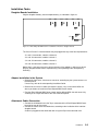
Installation Tasks
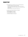
Daughter-Boards Installation
Plug the daughter-board(s) into the emplacement(s) as indicated in figure 23:
J41
J42
3
J31
J32
J22
J21
1
2
J23
J11
J13
0
J12
Figure 23. 4Port HiSpeed WAN Comm.: Installation of interface daughter-boards
The V24, V35 and V11 interface boards may be plugged into any of the four emplacements:
J11 and J12 connectors, noted as channel 0,
J21 and J22 connectors, noted as channel 1,
J31 and J32 connectors, noted as channel 2,
J41 and J42 connectors, noted as channel 3.
Notice that it is not necessary to use all the channels of the adapter, in which case do not
plug any daughter-board into the emplacement(s) corresponding to the non-operating
channel(s).
Adapter Installation in the System
• Remove the front cover, side cover or rear cover, according to your system to access to
the MCA planar.
If necessary, refer to the corresponding Installation Guide.
• Remove the rear cover in order to remove the cache, if any, in front of the MCA slot
where you choose to install the 4Port HiSpeed WAN Comm. board.
• Plug the 4Port HiSpeed WAN Comm. board into the defined MCA slot and secure it by
screwing in the 78-pin connector at the rear of the MCA planar.
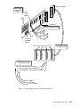
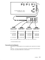
Attachment Cables Connection
• Connect the distribution box to the 78-pin connector of the 4Port HiSpeed WAN Comm.
board at the rear of the system.
• Connect the cables to the distribution box, according to the installation of the interface
daughter-board.
A cable is plugged into the distribution box using the 25-pin male connector end.
Installation
3-3
Warning: V24 attachment cable
Both ends of the V24 attachment cable are equipped with a 25-pin male connector, but
these two connectors are not the same, so be careful when you connect this type of cable.
To distinguish which connector to plug into the distribution box, look at the identification
written on the cable, near the connectors.
– Near the connector to be plugged into the distribution box, the identification begins
with:
SYSTEM
END
– Near the other connector, the identification begins with:
DEVICE
END
Warning:
Before connecting, make sure that the cable type fits with the interface type on each
channel; for instance, V24 cable and V24 interface daughter-board. When types of cable
and interface daughter-board are not the same, there may be a temporary problem such as
a short-circuit on power sources. This problem disappears after disconnecting the cable.
Figure 24 lists for each channel and interface type the cable which can be connected to the
distribution box.
3-4
HiSpeed WAN Comm. Installation and Service Guide
3
2
V24
V35
V11
V24
V35
V11
1
78–pin
Connector
V24
V35
V11
V24
V35
V11
0
4Port HiSpeed WAN Comm. adapter
and channels 0, 1, 2 and 3
Distribution
Box
3m
0
1
2
3
Cable to be connected
according to interface
plugged in channel 0
Cable to be connected
according to interface
plugged in channel 1
Cable to be connected
according to interface
plugged in channel 2
Cable to be connected
according to interface
plugged in channel 3
V24 90 246 001–001
V24 90 246 001–001
V24 90 246 001–001
V24 90 246 001–001
V35 76 958 248–001
V35 76 958 248–001
V35 76 958 248–001
V35 76 958 248–001
76 958 153–001
76 958 153–001
76 958 153–001
76 958 153–001
76 958 300–001
76 958 300–001
76 958 300–001
76 958 300–001
V11 90 166 001–002
V11 90 166 001–002
V11 90 166 001–002
V11
90 166 001–002
Figure 24. 4Port HiSpeed WAN Comm.: Connection of the cables on the distribution box
• Reinstall the different covers.
Connection to the Network
Connection to the network depends on the user application and in particular on the network
type.
Appendix D. Links gives some possible connections, especially direct connection between
two systems using HiSpeed WAN Comm. communications.
Installation
3-5
1Port HiSpeed WAN Comm. Hardware Installation
Preparation
Verify the hardware components. They are:
• 1Port HiSpeed WAN Comm. adapter,
• Cable(s), according to interface used.
If you are not sure of a component type, refer to the following table which gives, for each
component, the correspondence between type, MI (Marketing Identifier, that is commercial
identification) and the Identification number which is written on the component.
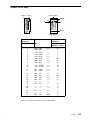
1Port HiSpeed WAN Comm. Components Identification
Designation
MI
Identification
Identification
Number
– V24
1Port HiSpeed WAN Comm. adapter – V24
DCCG049–xxxx
76 706 763–xxx
– V35
1Port HiSpeed WAN Comm. adapter – V35
with an adapter cable (30 cm)
DCCG050–xxxx
76 706 764–xxx
90 217 001–xxx
– V11
1Port HiSpeed WAN Comm. adapter – V11
with an adapter cable (30 cm)
DCGG051–xxxx
76 706 765–xxx
90 216 001–xxx
– V24
12m HiSpeed WAN Comm. cable V24
CBLG110–1900
76 958 057–xxx
– V35
10m cable remote sync V35/IF (25m/34m)
ISO std PTT/TRANSPAC
VCW 3657
76 958 153–xxx
10m cable remote sync V35/IF (25m/34m)
EIA standard
VCW 3660
76 958 300–xxx
10m cable remote sync V35/IF (25m/34m)
ISO 2593
VCW 3666
76 958 248–xxx
10m HiSpeed WAN Comm. cable V11
CBLG095–1900
90 166 001–xxx
Component
Adapters
Cables
– V11
Figure 25. 1Port HiSpeed WAN Comm. Components Identification
3-6
HiSpeed WAN Comm. Installation and Service Guide
Installation Tasks
Adapter Installation in the System
• Remove the front cover, side cover or rear cover, according to your system to access to
the MCA planar.
If necessary, refer to the corresponding Installation Guide.
• Remove the rear cover in order to remove the cache, if any, in front of the MCA slot
where you choose to install the 1Port HiSpeed WAN Comm. board.
• Plug the 1Port HiSpeed WAN Comm. board in the defined MCA slot and secure it by
screwing the 25-pin connector at the rear of the MCA planar.
Attachment Cables Connection
Warning:
Before connecting a cable on an adapter make sure that the cable type fits with the
interface type of the adapter; for instance V24 cable and 1Port HiSpeed WAN Comm.
adapter – V24. When types of cable and adapter are not the same, there may be a
temporary problem such as a short-circuit on power sources. This problem disappears after
disconnecting the cable.
Therefore, verify the type of your 1Port HiSpeed WAN Comm. adapter and refer to the
corresponding paragraph.
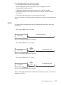
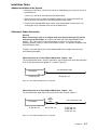
Cable Connection on a 1Port HiSpeed WAN Comm. adapter – V24
The V24 attachment cable is entirely symmetrical, you can plug either of the two connectors
in the 25-pin connector of the adapter. It is shown in Figure 26.
V24 attachment cable
V24 adapter
76 958 057–xxx
76 706 763–xxx
Figure 26. 1Port HiSpeed WAN Comm.–V24 Board
Cable Connection on a 1Port HiSpeed WAN Comm. adapter – V35
The V35 attachment cable may be one of the three cables listed on Figure 27.
V35 adapter
76 706 764–xxx
V35
adapter
cable
90 217 001–xxx
V35 attachment cable
76 958 248–xxx
76 958 300–xxx
76 958 153–xxx
Figure 27. 1Port HiSpeed WAN Comm.–V35 Board
Installation
3-7
Cable Connection on a 1Port HiSpeed WAN Comm. adapter – V11
The V11 attachment cable is shown in Figure 28.
V11 adapter
76 706 765–xxx
V11
adapter
cable
90 216 001–xxx
V11 attachment cable
90 166 001–xxx
Figure 28. 1Port HiSpeed WAN Comm.–V11 Board
Connection to the Network
Connection to the network depends on the user application and in particular on the network
type.
Appendix D. Links gives some possible connections, especially direct connection between
two systems using HiSpeed WAN Comm. communications.
3-8
HiSpeed WAN Comm. Installation and Service Guide
1Port HiSpeed WAN Comm–B Hardware Installation
Preparation
Verify the hardware components. They are:
• 1Port HiSpeed WAN Comm–B adapter,
• Interface daughter-board,
• Cable, according to interface used.
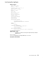
If you are not sure of a component type, refer to the following table which gives, for each
component, the correspondence between type, MI (Marketing Identifier, that is commercial
identification) and the Identification number which is written on the component.
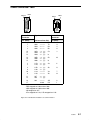
1Port HiSpeed WAN Comm–B Components Identification
Component
Designation
MI
Identification
Identification
Number
Adapter
1Port HiSpeed WAN Comm–B adapter
DCCG058–0000 76 729 218–001
Daughter–
Boards
V24 HiSpeed WAN Comm. interface card
DCCG047–0000 76 706 767–001
V35 HiSpeed WAN Comm. interface card
DCCG045–0000 76 706 768–001
V11 HiSpeed WAN Comm. interface card
DCCG046–0000 76 706 769–002
– V24
10m HiSpeed WAN Comm. cable V24
CBLG087–1900
90 246 001–001
– V35
10m cable remote sync V35/IF (25m/34m)
ISO std PTT/TRANSPAC
VCW 3657
76 958 153–001
10m cable remote sync V35/IF (25m/34m)
EIA standard
VCW 3660
76 958 300–001
10m cable remote sync V35/IF (25m/34m)
ISO 2593
VCW 3666
76 958 248–001
10m HiSpeed WAN Comm. cable V11
CBLG095–1900
90 166 001–002
Cables:
– V11
Figure 29. 1Port HiSpeed WAN Comm–B Components Identification
Installation
3-9
Installation Tasks
Daughter-Boards Installation
Plug the daughter-board (V24, V35 or V11) into the emplacement as indicated in the figure:
25–pin
connector
76 729 218–001
V24
76 706 767–001
V35
76 706 768–001
V11
76 706 769–002
Figure 30. 1Port HiSpeed WAN Comm–B: Installation of Interface Daughter-board
Adapter Installation in the System
• Remove the front cover, side cover or rear cover, according to your system to access to
the MCA planar.
If necessary, refer to the corresponding Installation Guide.
• Remove the rear cover in order to remove the cache, if any, in front of the MCA slot
where you choose to install the 1Port HiSpeed WAN Comm–B board.
• Plug the 1Port HiSpeed WAN Comm–B board in the defined MCA slot and secure it by
screwing in the 25-pin connector at the rear of the MCA planar.
Attachment Cables Connection
Connect the cable to the 25-pin connector of the 1Port HiSpeed WAN Comm–B board at the
rear of the system, according to the installation of the interface daughter-board.
A cable is plugged into the adapter connector using the 25-pin male connector end.
Warning:
Before connecting, make sure that the cable type fits with the interface type; for
instance V24 cable and V24 interface daughter-board. When types of cable and interface
daughter-board are not the same, there may be a temporary problem such as a short-circuit
on power sources. This problem disappears after disconnecting the cable.
So verify the type of your 1Port HiSpeed WAN Comm–B adapter and refer to the
corresponding paragraph.
3-10
HiSpeed WAN Comm. Installation and Service Guide
Cable Connection on a 1Port HiSpeed WAN Comm–B adapter – V24
V24
V24 attachment cable
90 246 001–001
76 729 218–001
and
76 706 767–001
Figure 31. 1Port HiSpeed WAN Comm–B–V24 Board
Warning: V24 attachment cable
Both ends of the V24 attachment cable are equipped with a 25-pin male connector, but
these two connectors are not the same, so be careful when you connect this type of cable.
To distinguish which connector to plug into the distribution box, look at the identification
written on the cable, near the connectors.
– Near the connector to be plugged into the distribution box, the identification begins
with:
SYSTEM
END
– Near the other connector, the identification begins with:
DEVICE
END
Cable Connection on a 1Port HiSpeed WAN Comm–B adapter – V35
The V35 attachment cable may be one of the three cables listed on the figure 32.
V35
V35 attachment cable
76 958 248–001
76 958 300–001
76 958 153–001
76 729 218–001
and
76 706 768–001
Figure 32. 1Port HiSpeed WAN Comm–B–V35 Board
Cable Connection on a 1Port HiSpeed WAN Comm–B adapter – V11
V11
76 729 218–001
and
76 706 769–002
V11 attachment cable
90 166 001–002
Figure 33. 1Port HiSpeed WAN Comm–B–V11 Board
Installation
3-11
Connection to the Network
Connection to the network depends on the user application and in particular on the network
type.
Appendix D. Links gives some possible connections, especially direct connection between
two systems using HiSpeed WAN Comm. communications.
3-12
HiSpeed WAN Comm. Installation and Service Guide
Software Installation
The software installation is common to all HiSpeed WAN Comm. adapter types installed in
the system. It must be performed by the system administrator (root authority).
The HiSpeed WAN Comm. software (bullx25) is installed using the standard software
installation procedure. Refer to the booklet provided with the Communications Software
CD-ROM for more information about installation of the current release.
bullx25 comes in three packages:
1. bullx25.board, which is mandatory in any case (HiSpeed WAN Comm. adapter
accessed by any communications provider (TCP/IP, OSI, etc.) and is made of the
following OPPs,
bullx25.board.mcode
microcode
bullx25.board.diag
diagnostic tests
bullx25.board.rte
drivers and daemons
bullx25.board.smit
SMIT configurator (adapter)
bullx25.board.com
commands
2. bullx25.tcpip, which is necessary only in case of a HiSpeed WAN Comm. adapter
accessed using TCP/IP, it is made of the following OPPs,
bullx25.tcpip.rte
drivers and daemons
bullx25.tcpip.smit
SMIT configurator (TCP/IP)
bullx25.tcpip.com
methods
3. bullx25.xpi, which is necessary only in case of a HiSpeed WAN Comm. adapter
accessed using XPI, it is made of the following OPPs,
bullx25.xpi.rte
drivers and daemons
bullx25.xpi.smit
SMIT configurator (XPI)
bullx25.xpi.com
methods
Note: The OPPs are roughly described and listed only for information. It is strongly
recommended to install the whole packages.
This product uses iFOR/LS encrypted license keys for license management. It supports the
’Nodelocked’ license type only. License status is validated only when the product is used,
thus permitting installation and configuration without need of the license key.
Refer to the iFOR/LS Installation Notice and Password Order Form delivered with your
Communications Product.
Refer to the SRB file for details on how the product uses the license key.
The availability of a bullx25 license can be checked using the funstat command.
Installation
3-13
System Reconfiguration
After having loaded the software you must re-configure the operating system to load the
HiSpeed WAN Comm. device driver. This will download the microcode to the adapter and
change its status to ”available”.
The procedure depends on the type of the HiSpeed WAN Comm. adapter:
1. If the adapter type is 4Port HiSpeed WAN Comm., 1Port HiSpeed WAN Comm. or 1Port
HiSpeed WAN Comm–B
To reconfigure the system, you can use:
– either the system reboot
– or the cfgmgr command
#cfgmgr
– or the smit interface
#smit dev
and choose the sub-menu
Configure Devices Added after IPL
2. If the adapter is a 1Port WAN Comm Adapter (ISA):
The adapter must be declared to the system using the smit interface
#smit isa
– Choose the sub-menu
Add an ISA Adapter
– Select
atrfut isa 1port X25 Comm Adapter ISA
– Select
bus1 Available 00–10 ISA Bus
A message is then displayed
fun[x] defined
where x is equal to 0 for the first adapter declared, 1 for the second, etc.
– To update the adapter configuration, choose the sub-menu
Change / Show Characteristics of an ISA Adapter
– Select in the list, the adapter to be configured, for instance fun1
Change / Show Characteristics of an ISA Adapter
Device Name
Slot on the ISA Bus
Bus I/O Address
Physical Interface Line
fun1
[1]
[0x360]
[V24]
+
+
+
Where
Slot on the ISA Bus is the slot where the adapter is plugged (1, 2 or 3)
Bus I/O Address is the value of jumpers on the board (0x300 to 0x370)
Physical Interface Line depends on the type of the adapter (V24, V35 or V11).
3-14
HiSpeed WAN Comm. Installation and Service Guide
Installation Verification
You can check the successful installation with the lsdev command, which lists the adapters
installed on the system.
• For a 4Port HiSpeed WAN Comm. adapter
#lsdev –C –H –t mcfuthd4
name
status
location
description
fun0
Available
00–01
4Port HiSpeed WAN Comm Adapter
• For a 1Port HiSpeed WAN Comm. adapter
#lsdev –C –H –t mcfut
name
status
location
description
fun1
Available
00–02
1Port HiSpeed WAN Comm Adapter
• For a 1Port HiSpeed WAN Comm–B adapter
#lsdev –C –H –t mcfutb
name
status
location
description
fun2
Available
00–03
1Port HiSpeed WAN Comm Adapter – B
• For a 1Port WAN Comm Adapter (ISA)
#lsdev –C –H –t atrfut
name
status
location
fun0
Available
00–11
description
1Port WAN Comm Adapter ISA
In any case, the adapter must appear as Available.
Installation
3-15
Configuration
Configuration of a HiSpeed WAN Comm. adapter consists of:
• configuration of each HiSpeed WAN Comm. line, see on page 3-17,
• configuration of TCP/IP on HiSpeed WAN Communications, if TCP/IP applications are
using HiSpeed WAN Communications, see on page 3-18,
• configuration of OSI Stack on HiSpeed WAN Communications, if OSI applications are
using HiSpeed WAN Communications, see on page 3-19.
• configuration of XPI on HiSpeed WAN Communications, for applications using XPI
through XX25 and HiSpeed WAN Communications, see on page 3-20.
The configuration tasks to be executed when using these procedures and all the
configuration parameters are described in:
• HiSpeed WAN Comm. adapter configurator, on page 4-2,
• TCP/IP on HiSpeed WAN Comm. configurator, on page 4-25,
• Configuring the OSI Stack Using SMIT described in OSI Services Reference Manual,
• XPI on HiSpeed WAN Comm. configurator, on page 4-33.
Three procedures, mandatory when loading configuration on a device and when running
tests, are described in this section:
• How to stop and restart TCP/IP applications, see on page 3-21,
• How to stop and restart OSI applications, see on page 3-21,
• How to stop and restart XPI (XX25) applications, see on page 3-21.
3-16
HiSpeed WAN Comm. Installation and Service Guide
How to Configure a HiSpeed WAN Comm. Line
1. Refer to the subscription sheet in order to enter the correct value of the parameters to
configure, then run the HiSpeed WAN Comm. configurator using the command
#smit x25d
This procedure lists only the major parameters to configure and check. The other
parameters are defined by default.
2. Select the entries:
Change/Show Characteristics of a HiSpeed WAN Comm. Adapter
Physical Parameters on page 4-5
– The clock is generally provided externally, but if the clock is generated internally
configure the speed of the line.
3. Select the entries:
Change/Show Characteristics of a HiSpeed WAN Comm. Adapter
Frame Parameters on page 4-7
– Check type of line (DTE/DCE),
– Check window size,
– Check timers,
– Check connection mode (active/passive).
4. Select the entries:
Change/Show Characteristics of a HiSpeed WAN Comm. Adapter
Network Parameters on page 4-9
– Enter the NUA,
– Enter the number of the virtual circuits subscribed (SVCs and eventually PVCs) and
the associated logical channel numbers,
– Check packet level mode (DTE/DCE),
– Define if the local address is transmitted or not (must not be transmitted if connection
to the French X.25 TRANSPAC network),
– Check timers
– Check packet size, packet window and throughput class.
5. Select the entry:
Generate a Current Configuration for a HiSpeed WAN Comm. Adapter
on page 4-23.
6. Select the entry:
Load HiSpeed WAN Comm. Adapter with the last Generated Configuration
on page 4-24.
Installation
3-17
How to Configure TCP/IP on HiSpeed WAN Communications
1. Configure HiSpeed WAN Comm. line on page 3-17.
2. Add entries concerning the local and remote hosts in the /etc/hosts file
#smit tcpip
Select the entries
Further Configuration
Name Resolution
Hosts Table (/etc/hosts)
Add a Host
3. Create the IP/X25 interface corresponding to the physical line, if it does not exist
#smit inet
Select the entry
Add a Network Interface
Add a HiSpeed WAN Comm. Network Interface on page 4-26
A HiSpeed WAN Comm. network interface is then created under the name xd<n>
4. Initialize and start the IP/X25 interface corresponding to the physical line
#smit inet
Select the entry
Change/ Show Characteristics of a Network Interface
Select from the list the IP/X25 interface previously created and change the current state
to up.
5. Map IP addresses to X.25 NUAs
For each remote host, create an entry in the IP/HiSpeed WAN Comm. translation table to
create correspondence between IP addresses and NUAs
#smit inetx25d
Select the entries
Add an IP/HiSpeed WAN Comm. Host Entry
Add a Switched Virtual Circuit (SVC) IP/HiSpeed WAN Comm. Host Entry
on page 4-30
Enter the remote hostname and its NUA.
6. Check that everything is correct using netstat –r
7. Check that the local site is configured on the remote machines in the same way
8. Test the connection with the remote host using ping.
3-18
HiSpeed WAN Comm. Installation and Service Guide
How to Configure OSI Stack on HiSpeed WAN Communications
The OSI configuration must first be performed according to Configuring the OSI Stack
Using SMIT described in OSI Services Reference Manual.
1. Configure HiSpeed WAN Comm. line as described on page 3-17
2. Select an unloaded OSI configuration
#smit OSIconf
Select the entries
Configuration Management
Select a Configuration
3. Declare the HiSpeed WAN Comm. adapter in the selected OSI configuration
#smit OSIconf
Select the entries
Configuration Definition
Communications Adapter Access
Add Communications Adapters
HiSpeed WAN Comm Adapter
4. Unload the currently loaded OSI configuration (if any), after stopping all running OSI
applications not declared to the Stack Application Support (SAS)
#smit OSIconf
Select the entry
Unload Current Loaded Configuration
5. Load the new OSI configuration
#smit OSIconf
Select the entry
Load Last Selected Configuration
Installation
3-19
How to Configure XPI on HiSpeed WAN Communications
1. Configure HiSpeed WAN Comm. line on page 3-17
2. Create and start the XPI interface corresponding to the physical line, if it does not exist.
#smit xpi_xd_if
Select the entry
Add a Network Interface on page 4-34
Select the physical line x25l<n> from the list, an XPI interface is then created under the
name xpi_xd<n> in the state Available.
3. Initialize and start the XPI interface corresponding to the physical line, if it already exists
but is not activated (stopped).
#smit xpi_xd_if
Select the entry
Change/Show Characteristics of a Network Interface on page 4-35
Select the network interface xpi_xd<n> from the list, and choose the action start
Warning:
Using XPI, the default routing is based on SPI routing (Subsequent Protocol Identifier), but
only 24 SPIs may be used at a time on each adapter.
To use addressing routing refer to Change/Show Incoming Calls Routing, on page 4-18.
3-20
HiSpeed WAN Comm. Installation and Service Guide
How to Stop and Restart TCP/IP Applications
1. Stop the TCP/IP applications accessing the HiSpeed WAN Comm. adapter concerned
2. Stop the IP interface using the HiSpeed WAN Comm. adapter
#smit inet
Select the entry
Change/ Show Characteristics of a Network Interface
Select from the list the IP/X25 interface and change the current state to detach
3. Stop all processes using the HiSpeed WAN Communications driver, such as:
xdmanage, xdmonitor, x25dstat
4. Execute the command, for instance funload, funautotest, etc..
5. Restart the IP interface
#smit inet
Select the entry
Change/ Show Characteristics of a Network Interface
Select from the list the IP/X25 interface and change the current state to up
6. Restart the TCP/IP applications
How to Stop and Restart OSI Stack Applications
1. Stop all the OSI applications not declared to the Stack Applications Support (SAS)
2. Unload the OSI stack and the applications declared to SAS
#osiunload
3. Execute the command, for instance funload, funautotest, etc..
4. Restart the OSI stack and the applications declared to SAS
#osiload
5. Restart the OSI applications not declared to SAS
How to Stop and Restart XPI (XX25) Applications
1. Stop the XPI (XX25) applications accessing the concerned HiSpeed WAN Comm.
adapter
2. Stop the XPI interface using the HiSpeed WAN Comm. adapter
#smit xpi_xd_if
Select the entry
Change/ Show Characteristics of a Network Interface
Select from the list the XPI interface and select the stop action
3. Stop all processes using the HiSpeed WAN Communications driver, such as:
xdmanage, xdmonitor, x25dstat
4. Execute the command, for instance funload, funautotest, etc..
5. Restart the IP interface
#smit xpi_xd_id
Select the entry
Change/ Show Characteristics of a Network Interface
Select from the list the XPI interface and select the start action
6. Restart the XPI (XX25) applications
Installation
3-21
3-22
HiSpeed WAN Comm. Installation and Service Guide
Chapter 4. Configurator
The configurator is common to all HiSpeed WAN Comm. adapter types. It must be used by
the system administrator (root authority) and is accessed through the smit command.
Enter:
smit
if you are using an X terminal,
smit –C
if you are using an ASCII terminal.
In this configurator description:
• the values between square braces (”[ ]”) are the default values,
• a + sign at the end of the line indicates that the parameter may be chosen in a list.
The HiSpeed WAN Comm. configurator is composed of:
• HiSpeed WAN Comm. Adapter configurator
on page 4-2,
• TCP/IP on HiSpeed WAN Comm. Configurator
on page 4-25,
• XPI Interface on HiSpeed WAN Comm. Configurator
on page 4-33.
Configuration
4-1
HiSpeed WAN Comm. Adapter Configurator
HiSpeed WAN Comm. Adapter Configuration Menu
Run
smit x25d
HiSpeed WAN
Comm. Adapter
Generation
of current
Configuration
List
Adapters
Tests
1
Load of
last generated
Configuration
Change/Show
Characteristics
XPI
lnterface
Management
2
Physical
Parameters
Network
Parameters
Frame
Parameters
Default PVC
Parameters
Incoming Calls
Routing
Clear
Current
Configuration
Specific PVC
Parameters
Four basic functions are effectively related to HiSpeed WAN Comm. adapter configuration:
• List of adapters
described on page 4-3,
• Change/Show characteristics of an adapter
described on page 4-4,
• Save current configuration of an adapter
described on page 4-23,
• Load the last saved configuration on an adapter
described on page 4-24,
The two other functions are not directly related to configuration but to:
4-2
1. Test of HiSpeed WAN Comm. adapter
described on page 5-2,
2. XPI Interface management
described on page 4-33.
HiSpeed WAN Comm. Installation and Service Guide
How to List HiSpeed WAN Comm. Adapters
Access
Using the HiSpeed WAN Comm. Adapter configurator, run the command:
smit x25d
Then select the function:
List Hispeed WAN Comm Adapters
Description
The list of the HiSpeed WAN Comm. lines, installed and configured in the system, is
displayed according to this format:
x25l<n>
<state>
00–ss–01–ll
HiSpeed WAN Comm. Adapter Line
<n>
line number (from 0 to the maximum number of lines in the system)
<state>
Available : the board is configured and loaded
Defined : the board is configured, but not loaded
or no daughter-board is plugged onto this channel
ss
slot number
ll
line number on the board (from 00 to 03)
For instance:
x25l0
x25l1
x25l2
x25l3
x25l4
x25l5
Available
Available
Available
Available
Available
Defined
00–02–01–00
00–04–01–00
00–04–01–01
00–04–01–02
00–04–01–03
00–03–01–00
Hispeed
Hispeed
Hispeed
Hispeed
Hispeed
Hispeed
WAN
WAN
WAN
WAN
WAN
WAN
Comm
Comm
Comm
Comm
Comm
Comm
Adapter
Adapter
Adapter
Adapter
Adapter
Adapter
Line
Line
Line
Line
Line
Line
Configuration
4-3
How to Change / Show Characteristics of a HiSpeed WAN
Comm. Adapter
Access
Using the HiSpeed WAN Comm. Adapter configurator, run the command:
smit x25d
Then select the function:
Change / Show Characteristics of a Hispeed WAN Comm Adapter
Description
This menu allows access to the configuration operations of a HiSpeed WAN Comm.
adapter. Select the line corresponding to the type of parameters to configure.
Change / Show Physical Parameters
see on page 4-5
Change / Show Frame Parameters
see on page 4-7
Change / Show Network Parameters
see on page 4-9
Change / Show Incoming Calls Routing
see on page 4-18
Change / Show Default for Permanent Virtual Circuits (PVC)
see on page 4-20
Change / Show a Specific Permanent Virtual Circuit (PVC)
see on page 4-21
Clear current configuration
4-4
HiSpeed WAN Comm. Installation and Service Guide
see on page 4-22
Change / Show Physical Parameters
Display and/or modification of the physical parameters, that is relative to the X.25.1 layer, of
an X.25 line selected from the list.
Change / Show Physical Parameters
Device name
Physical line interface
Clock signal
Line Opening Mode
x25l0
V24
[external]
[automatic]
+#
+#
Note: This menu may be accessed directly, using the command: smit x25datp
Physical Line Interface
Display the physical interface installed on this line.
List of possible values: [ V24 , V35 , V11 ]
Note: For a 1Port WAN Comm Adapter (ISA), the displayed value is not read directly on
the adapter, but has been previously configured when the adapter has been
declared present in the system. Refer to System Reconfiguration, on page 3-14.
Clock Signal
Origin of the clock signal:
external.
internal:
[external]
It is provided by the network or the peer equipment (local modem or
corresponding DCE).
It is provided by a baud rate generator on the adapter (meaningful if type
of line is DCE).
List of possible values for a line of a 4Port HiSpeed WAN Comm. adapter:
external 1200 2400 4800 9600 19200 48000 56000
128000 256000 512000 1024000 1536000 2000000
64000
List of possible values for the line of a 1Port HiSpeed WAN Comm. adapter or 1Port
HiSpeed WAN Comm–B adapter:
external 75 150 300 600 1200 2400 4800 9600 19200
48000 56000 64000 128000
List of possible values for the line of a 1Port WAN Comm Adapter (ISA):
external 75 150 300
48000 56000 64000
600
1200
2400
4800
9600
19200
Note: For 1Port HiSpeed WAN Comm. adapter or a 1Port WAN Comm Adapter (ISA),
equipped with a V35 interface, the origin of the clock signal cannot be chosen and is
fixed to external.
Note: For any type of HiSpeed WAN Comm. line, the range of possible values depends on
the type of the physical interface.
Configuration
4-5
Line Opening Mode
[automatic, manual]
Activation mode chosen for the line:
automatic:
manual:
4-6
the line is active at each loading of the board.
the line is inactive at each loading of the board. In that case, the command
”xdconnect on” must be run to make the line active. After this action, the
line has the same behavior as in automatic mode (included the case of
connection recovery).
HiSpeed WAN Comm. Installation and Service Guide
Change / Show Frame Parameters
Display and/or modification of the frame parameters, that is relative to the X.25.2 layer, of
an X.25 line selected from the list.
Change / Show Frame Parameters
Device name
Type of line
Frame window size
Frame modulo
T1 timer
T4 timer
N2 counter
Connection mode
x25l0
[DTE]
[7]
[8]
[30]
[80]
[10]
[passive]
+#
+#
+#
+#
+#
+#
+#
Note: This menu may be accessed directly, using the command: smit x25datf
Type of Line
[DTE]
Two possible values:
DTE
DCE
(Data Terminal Equipment)
(Data Communication Equipment)
The type of line is defined by the subscription.
Frame Window Size
[7]
Number of frames that can be outstanding without acknowledgment
Two possible ranges of values:
1 to 7
1 to 127
if frame modulo is 8
if frame modulo is 128
Frame Modulo
[8]
Numbering modulo used to order the frames within the frame window.
This parameter is noted in the subscription sheet.
Two possible values:
8
128
T1 Timer
[30]
T1 parameter is defined in the CCITT recommendation.
Time after which, if it has not been acknowledged, a frame is transmitted again.
The value must be in the range 1 to 32767 (multiple of 1/10 seconds) and lower than T4
timer.
T4 Timer
[80]
Time after which, if there was no activity on the line, an RR frame (Receive Ready) is sent.
Frame-layer recovery is started if no answer is received within T1.
Configuration
4-7
The value must be either 0 (meaning that T4 is disabled) or in the range 1 to 32767
(multiple of 1/10 seconds) and greater than T1 timer.
N2 Counter
[10]
N2 parameter is defined in the CCITT recommendation.
Maximum number of retries to send a frame.
The value must be in the range 0 to 32767.
Connection Mode
[passive]
Two possible connection modes on the frame layer:
passive
X.25.2 layer of the line waits for an SABM frame from the network to
determine whether the network is connected.
active
X.25.2 layer of the line sends an SABM frame to the network, waiting for
the network to send an UA frame to acknowledge that it is connected.
The connection mode is defined at subscription time.
Note:
The following table lists the value of Connection Mode when a HiSpeed WAN Comm.
adapter is connected to another Bull X.25 adapter through a private network.
X.25 adapter communicating with the
HiSpeed WAN Comm. adapter
HiSpeed WAN Comm. adapter
= DTE
HiSpeed WAN Comm. adapter
= DCE
HiSpeed WAN Comm.
on DPX/20
at least one of the two adapters
must be active
at least one of the two adapters
must be active
Co-Processor2
on DPX/20
at least one of the two adapters
must be active
at least one of the two adapters
must be active
CFS
on DPX/2
passive
passive
FECP
on DPX/2
active
active or passive
MTB4-A
on DPX/2
active
active or passive
4-8
HiSpeed WAN Comm. Installation and Service Guide
Change / Show Network Parameters
Display and/or modification of the network and packet parameters, that are relative to the
X.25.3 layer, of an X.25 line selected from the list.
Change / Show Network Parameters
Device name
Local network user address (NUA)
Lowest logical channel number for an incoming SVC
Number of logical channels for incoming SVCs
Lowest logical channel number for a two–way SVC
Number of logical channels for two–way SVCs
Lowest logical channel number for an outgoing SVC
Number of logical channels for outgoing SVCs
Lowest logical channel number for a PVC
Number of PVCs
Packet level mode
Optional addresses in call request/accept packet
Packet modulo
x25l0
[1101]
[0]
[0]
[1]
[64]
[0]
[0]
[1]
[0]
[DTE]
[allow]
[8]
#
+#
+#
+#
+#
+#
+#
+#
+#
+#
+#
+#
Defined Timers
**********
ISO8208 T20 timer
ISO8208 T21 timer
ISO8208 T22 timer
ISO8208 T23 timer
Inactivity timer
[180]
[200]
[180]
[180]
[0]
+#
+#
+#
+#
+#
Default Attributes for SVCs
**********
Default receive packet size
Default transmit packet size
Default receive packet window
Default transmit packet window
Default receive throughput class
Default transmit throughput class
[128]
[128]
[2]
[2]
[9600]
[9600]
+#
+#
+#
+#
+#
+#
Maximum Negotiable Attributes for SVCs
**********
Maximum receive packet size
Maximum transmit packet size
Maximum receive packet window
Maximum transmit packet window
Maximum receive throughput class
Maximum transmit throughput class
[128]
[128]
[7]
[7]
[48000]
[48000]
+#
+#
+#
+#
+#
+#
Optional Facilities
**********
Outgoing call acceptance (CUG)
Incoming call
Network user identification
Redirection notification
Call redirection
Charging information
Local charging prevention
Reverse charging acceptance
Fast select
Throughput class negotiation
Flow control negotiation
Outgoing call
Incoming call
Packet retransmission
[enable]
[enable]
[enable]
[enable]
[enable]
[enable]
[enable]
[disable]
[enable]
[enable]
[enable]
[enable]
[enable]
[disable]
+#
+#
+#
+#
+#
+#
+#
+#
+#
+#
+#
+#
+#
+#
Configuration
4-9
Change / Show Network Parameters
1st CUG
*********
CUG state
CUG value
[two–way]
[00]
+#
#
2nd CUG
*********
CUG state
CUG value
[disable]
[00]
+#
#
[disable]
[00]
+#
#
.........
8th CUG
*********
CUG state
CUG value
Note: This menu may be accessed directly, using the command: smit x25datn
Local Network User Address (NUA)
The X25 subscription number is given in the subscription sheet in the form of an 8 digit
number preceded by a prefix.
The user must define the local address for private connections.
Virtual Circuits and Logical Channel Numbers
The number of virtual circuits which may be used on a HiSpeed WAN Comm. line depends
on the type of the line:
• up to 1024 virtual circuits on a 4Port HiSpeed WAN Comm. line,
• up to 256 virtual circuits on 1Port HiSpeed WAN Comm., 1Port HiSpeed WAN Comm–B
and 1Port WAN Comm Adapter (ISA) line.
The logical channel number is in the range 0 to 4095. The logical channel numbers are
allocated to virtual circuits, according to the virtual circuit types and according to the
connection mode:
• DTE, refer to figure 34
PVCs
incoming SVCs
0
two–way SVCs
outgoing SVCs
4095
on a DTE
Figure 34. Logical channel numbering according to virtual circuit types on a DTE
• DCE, refer to figure 35
PVCs
0
outgoing SVCs
two–way SVCs
incoming SVCs
on a DCE
Figure 35. Logical channel numbering according to virtual circuit types on a DCE
4-10
HiSpeed WAN Comm. Installation and Service Guide
4095
For each type, the number of virtual circuits and the logical channel numbers are defined by
the subscription.
Lowest logical channel number for an incoming SVC
Range of possible values:
[0]
0 to 4095
Number of logical channels for incoming SVCs
Range of possible values:
[0]
0 to 1024 on a 4Port HiSpeed WAN Comm. line
0 to 256 on a 1Port HiSpeed WAN Comm., 1Port HiSpeed WAN Comm–B
and 1Port WAN Comm Adapter (ISA) line
Lowest logical channel number for a two-way SVC
Range of possible values:
[1]
0 to 4095
Number of logical channels for two-way SVCs
Range of possible values:
[64]
0 to 1024 on a 4Port HiSpeed WAN Comm. line
0 to 256 on a 1Port HiSpeed WAN Comm., 1Port HiSpeed WAN Comm–B
and 1Port WAN Comm Adapter (ISA) line
Lowest logical channel number for an outgoing SVC
Range of possible values:
[0]
0 to 4095
Number of logical channels for outgoing SVCs
Range of possible values:
[0]
0 to 1024 on a 4Port HiSpeed WAN Comm. line
0 to 256 on a 1Port HiSpeed WAN Comm., 1Port HiSpeed WAN Comm–B
and 1Port WAN Comm Adapter (ISA) line
Lowest logical channel number for a PVC
Range of possible values:
[1]
1 to 4095
Number of PVCs
Range of possible values:
[0]
0 to 1024 on a 4Port HiSpeed WAN Comm. line
0 to 256 on a 1Port HiSpeed WAN Comm., 1Port HiSpeed WAN Comm–B
and 1Port WAN Comm Adapter (ISA) line
Packet level mode
[DTE]
Two possible connection modes on the network layer:
DTE
X.25.3 layer of the line waits for a restart-indication packet from the
network to determine whether the network is connected. The logical
channel numbers are allocated starting from the highest possible values.
DCE
X.25.3 layer of the line sends a restart-request packet to the network,
waiting for the peer X.25.3 layer to send a restart-confirmation packet to
acknowledge that it is connected. The logical channel numbers are
allocated starting from the lowest possible values.
Configuration
4-11
The packet level mode is defined by the subscription, it is generally the same value as the
frame parameter Type of line.
Optional address in call request/accept packet [allow]
Modification or not of the addresses in the call-accepted and call-request packets
Two possible values:
allow
Packets are transmitted without any address changes
forbid
Packets are transmitted with some address modifications.
In call-request packets, the Network User Address (NUA) is removed from
the calling address field but the sub-address is kept.
In call-accepted and clear packets, both the called and calling addresses
are removed.
This forbid option must be set to connect to the French TRANSPAC X.25
network.
Packet Modulo
[8]
Numbering modulo used to order the packets.
Two possible values:
8
128
ISO 8208 Defined Timers
T20 timer
[180]
Time within which a restart-confirmation packet should be received after transmission of a
restart-request packet
The value must be either 0 (meaning that T20 is disabled) or in the range 1 to 255 (in
seconds)
T21 timer
[200]
Time within which a call-connected, clear-indication or incoming-call packet should be
received after transmission of a call-request packet.
The value must be either 0 (meaning that T21 is disabled) or in the range 1 to 255 (in
seconds)
T22 timer
[180]
Time within which a reset-confirmation packet should be received after transmission of a
reset-request packet.
The value must be either 0 (meaning that T22 is disabled) or in the range 1 to 255 (in
seconds)
T23 timer
[180]
Time within which a clear-confirmation packet should be received after transmission of a
clear-request packet.
The value must be either 0 (meaning that T23 is disabled) or in the range 1 to 255 (in
seconds)
Inactivity timer
[0]
Time within which packet(s) should be exchanged. If no packet is exchanged within this
time, the connection is closed.
4-12
HiSpeed WAN Comm. Installation and Service Guide
The value must be either 0 (meaning that the inactivity timer is disabled) or in the range 1
to 255 (in seconds)
Default Attributes for SVCs
The default value of an attribute cannot be set higher than the maximum negotiable value
for this attribute (see Maximum Negotiable Attributes for SVCs). However, the maximum
negotiable value can be increased before a default value is modified.
Any attribute value may be modified for an individual call, using the optional facilities in the
call-request packet.
Default receive packet size
List of possible values:
[128]
16 32 64 128 256 512 1024 2048 4096
Default transmit packet size
List of possible values:
[128]
16 32 64 128 256 512 1024 2048 4096
Default receive packet window
Two possible ranges of values:
1 to 7
1 to 127
[2]
if packet modulo is 8
if packet modulo is 128
Default transmit packet window [2]
Two possible ranges of values:
1 to 7
1 to 127
if packet modulo is 8
if packet modulo is 128
Default receive throughput class
List of possible values:
75
150
300
[9600]
600
1200
Default transmit throughput class
List of possible values:
[9600]
75
1200
150
300
600
2400
4800
9600
19200
48000
2400
4800
9600
19200
48000
Configuration
4-13
Maximum Negotiable Attributes for SVCs
For each way (reception and transmission) of a switched virtual circuit, three attributes have
to be configured:
packet size
defined in bytes
packet window
number of packets that can be outstanding without acknowledgment
throughput class
speed at which the packets travel through the network
During a connection, there may be, using optional facilities, negotiations concerning flow
control (packet size and window) or throughput class in order to use temporary values
instead of default values defined in Default Attributes for SVCs. The attributes values may
vary from the minimum value to the maximum negotiable value.
Maximum receive packet size
List of possible values:
[128]
16 32 64 128 256 512 1024 2048 4096
Maximum transmit packet size
List of possible values:
[128]
16 32 64 128 256 512 1024 2048 4096
Maximum receive packet window
Two possible ranges of values:
1 to 7
1 to 127
[7]
if packet modulo is 8
if packet modulo is 128
Maximum transmit packet window [7]
Two possible ranges of values:
1 to 7
1 to 127
if packet modulo is 8
if packet modulo is 128
Maximum receive throughput class
List of possible values:
75
150
300
600
Maximum transmit throughput class
List of possible values:
75
4-14
150
300
600
HiSpeed WAN Comm. Installation and Service Guide
[48000]
1200
2400
4800
9600
19200
48000
4800
9600
19200
48000
[48000]
1200
2400
Optional Facilities
Optional facilities are those which may or may not be offered by the network provider and to
which customers choose whether or not to subscribe. The facilities implemented on
HiSpeed WAN Comm. adapters refer to these main concerns:
– incoming and outgoing data accesses, in general or according to the membership of a
Closed User Group,
– redirection and retransmission of data,
– charging of communications.
Some facilities are valid for all calls whereas other ones must be specifically requested for
the duration of the call. In this case, a facility request is inserted in the call packets, either in
call-request packet or in call-accepted packet, such as described in the figure 36.
Call Request
Calling
Facility Request
DTE
Call Connected
Facility Indication
Incoming Call
X.25
Network
DCE
Facility Indication
Called
DTE
Call Accepted
Facility Request
Figure 36. Facilities and Call Packets
The facilities and their coding are described in the X.25 CCITT recommendation.
Outgoing call acceptance (CUG)
[enable]
Acceptance of outgoing calls from a user to users who do not belong to the same Closed
User Group.
Two possible values:
enable
disable
If there is any such outgoing call, it is cleared immediately, returning a
clear-indication packet to the user
Incoming call acceptance (CUG)
[enable]
Acceptance by a user of incoming calls from users who do not belong to the same Closed
User Group
Two possible values:
enable
disable
If there is any such incoming call, it is cleared immediately
Network user identification
[enable]
Possibility for a user to give to the network, in a call or data packet, information about
charging, security or network management.
Two possible values:
enable
disable
Configuration
4-15
Redirection notification
[enable]
Indication to a DTE receiving a call whether this one has been redirected.
Two possible values:
enable
disable
Call redirection
[enable]
Redirection of a call to another DTE when the first one is busy or out of order.
Two possible values:
enable
disable
Charging information
[enable]
Retrieval of information in order to compute the billing.
Two possible values:
enable
disable
Local charging prevention
[disable]
Prevention of outgoing and incoming calls to be paid for locally.
Two possible values:
enable
If so, any outgoing call must specify reverse charging and incoming calls
which ask for reverse charging are rejected.
disable
Default is disable.
Reverse charging acceptance
[disable]
Acceptance of incoming calls which ask for reverse charging.
Two possible values:
enable
If so, the incoming calls may be paid for locally, if the reverse charging is
asked and the ’Local charging prevention’ disabled.
disable
Default is disable.
Fast select
[enable]
Option of a virtual call facility which allows inclusion of data in call-setup and call-clearing
packets.
Two possible values:
enable
disable
Throughput class negotiation
[enable]
Possibility for a DTE to negotiate the speed at which its packets travel through the network.
Two possible values:
enable
disable
4-16
The default value is selected and the incoming throughput class value is
checked for acceptability; if unacceptable, the call is cleared.
HiSpeed WAN Comm. Installation and Service Guide
Flow control negotiation
[enable]
Possibility for a DTE to negotiate the flow control parameters (packet and window sizes). If
the flow control parameters are not present in the call packet, the default values are
selected.
Two possible values:
enable
disable
Outgoing call
Two possible values:
enable
disable
A disconnect indication is returned to any application which processes a
call-request packet
Incoming call
Two possible values:
enable
disable
[enable]
[enable]
A clear-indication packet is sent on reception of a call-request packet
Packet retransmission
[enable]
Retransmission of data packets after reception of a reject packet. The retransmission
begins with the sequence number given in the reject packet.
Two possible values:
enable
disable
Closed User Group
A Closed User Group (CUG) is a group of users who can communicate with other users in
the group, but not with users outside the group. The CUG selection facility allows the DTE
to specify which CUG it will be working with.
In this HiSpeed WAN Comm. implementation, a DTE may belong to up to 8 CUGs. Here
are the parameters to configure for a DTE, the membership of a CUG.
CUG state
Four possible values:
[disable]
disable
incoming
outgoing
two-way
CUG value
[no default value]
Closed User Group name which is defined by all the users which are members of this group
The optional facilities, outgoing call acceptance and incoming call acceptance, may
however modify these communications rules.
Configuration
4-17
Change / Show Incoming Calls Routing
Display and/or modification of the routing parameters related to an X.25 line selected from
the list.
Warning:
This facility must be used carefully, the default configuration being valid for most
of standard cases.
The addressing routing solves possible conflicts between applications using the
same SPI (Subsequent Protocol Identifier) on different communications stacks.
If you are not concerned by this problem, keep the default configuration and do
not bother reading the following.
Change / Show Incoming Calls Routing
Device name
x25l0
Local network user address (NUA)
1000
OSI stack local network address
OSI stack address
[]
[used]
+
#
XPI/XX25 local network address
XPI/XX25 address
[]
[unused]
+
HVX stack local network address
HVX stack address
[]
[unused]
+
#
#
Note: This menu may be accessed directly, using the command: smit x25datr
This incoming calls routing concerns only the incoming calls from adapter to stacks (and not
from stacks to applications).
SPI routing has a greater priority than addressing routing.
The communications stacks act in this way:
• OSI Stack does not declare the application SPI to the adapter. It works only with the
addressing routing.
• XPI (XX25) and HVX stacks declare the application SPI to the adapter except if the
addressing routing is specified, that is if the flag is set to used.
Stack Local Network Address
Local network user address (NUA) and/or sub-address
Each address cannot have more than 15 decimal digits.
If the optional address in call request/accept packet is not allowed (i.e. French network
Transpac), only the sub-address is useful.
Stack Address
Flag which allows to use or not the address for the considered stack
Two possible values:
used
unused
4-18
HiSpeed WAN Comm. Installation and Service Guide
Warning:
It is impossible to configure the same address (with the flag set to used) for two different
stacks.
Example
How to manage the coexistence between these two applications: PAD over OSI Stack and
Videotext over XPI/XX25 Stack by using the sub-addressing routing.
PAD (OSI Stack)
with SPI 0x01000000
Line NUA 1001
OSI sub-address none
OSI Stack address used
Videotext (XPI/XX25 Stack)
with SPI 0x01000000
Line NUA 1001
XPI/XX25 sub-address 34
XPI/XX25 Stack address used
If the default incoming calls routing is used, the XPI/XX25 stack declares to the line that it
uses the SPI 0x01000000 (Videotext): all the incoming calls with the SPI 0x01000000 (PAD
inlcuded) are routed to the XPI stack.
Consequently, it is mandatory to change the incoming calls routing.
Change / Show Incoming Calls Routing
Device name
xxxx
Local network user address (NUA)
1000
OSI stack local network address
OSI stack address
[]
[used]
#
XPI/XX25 local network address
XPI/XX25 address
[100134]
[used]
+
HVX stack local network address
HVX stack address
[]
[unused]
+
+
#
#
All incoming calls with the address 100134 are routed to the XPI/XX25 Stack, and the
others are routed to the OSI Stack, irrespective of the SPIs.
To receive all incoming calls which are not switched to the other configurated routes (default
routing), the address must be null and the address flag set to used. This is the default
configuration address for OSI Stack.
Warning: Be careful, if a Local Network Address is set on OSI, because many OSI
applications use the default routing.
Configuration
4-19
Change / Show Default PVC Parameters
Display and/or modification of the default maximum values of PVCs parameters relative to
an X.25 line selected in the list.
Change / Show Default PVC Parameters
Device name
PVC Default
PVC Default
PVC Default
PVC Default
PVC Default
PVC Default
receive packet size
transmit packet size
receive packet window
transmit packet window
receive throughput class
transmit throughput class
x25l0
[128]
[128]
[2]
[2]
[9600]
[9600]
+#
+#
+#
+#
+#
+#
Note: This menu may be accessed directly, using the command: smit x25datcsd
PVC Default receive packet size
List of possible values:
[128]
16 32 64 128 256 512 1024 2048 4096
PVC Default transmit packet size [128]
List of possible values:
16 32 64 128 256 512 1024 2048 4096
PVC Default receive packet window [2]
Two possible ranges of values:
1 to 7
1 to 127
if packet modulo is 8
if packet modulo is 128
PVC Default transmit packet window [2]
Two possible ranges of values:
1 to 7
1 to 127
if packet modulo is 8
if packet modulo is 128
PVC Default receive throughput class [9600]
List of possible values:
75
150
300
600
1200
2400
4800
9600
19200
48000
4800
9600
19200
48000
PVC Default transmit throughput class [9600]
List of possible values:
75
4-20
150
300
600
HiSpeed WAN Comm. Installation and Service Guide
1200
2400
Change / Show Specific PVC Parameters
Display and/or modification of the maximum values of a specific PVC parameters (PVC
associated with an X.25 line selected in the list).
Change / Show Specific PVC Parameters
PVC Number to Change / Show
[]
+#
Device name
PVC Number to Change / Show
PVC receive packet size
PVC transmit packet size
PVC receive packet window
PVC transmit packet window
PVC receive throughput class
PVC transmit throughput class
x25l0
1
[128]
[128]
[2]
[2]
[9600]
[9600]
+#
+#
+#
+#
+#
+#
Note: This menu may be accessed directly, using the command: smit x25datcsa
PVC Number to Change / Show
press [F4] or select List
PVC receive packet size [128]
List of possible values:
16 32 64 128 256 512 1024 2048 4096
PVC transmit packet size [128]
List of possible values:
16 32 64 128 256 512 1024 2048 4096
PVC receive packet window [2]
Two possible ranges of values:
1 to 7
1 to 127
if packet modulo is 8
if packet modulo is 128
PVC transmit packet window [2]
Two possible ranges of values:
1 to 7
1 to 127
if packet modulo is 8
if packet modulo is 128
PVC receive throughput class [9600]
List of possible values:
75
150
300
600
1200
2400
4800
9600
19200
48000
2400
4800
9600
19200
48000
PVC transmit throughput class [9600]
List of possible values:
75
150
300
600
1200
Configuration
4-21
Clear Current Configuration
Sets to their default values all the parameters:
• Physical Parameters
• Frame Parameters
• Network Parameters
• Default PVC Parameters
• Specific PVC Parameters
• Incoming Calls Routing
Note: This may be useful before reconfiguring a HiSpeed WAN Comm. line.
There is no FastPath to access directly to this SMIT functionality, but you can use the
xdclear command.
4-22
HiSpeed WAN Comm. Installation and Service Guide
How to Generate Current Configuration for a HiSpeed WAN
Comm. Adapter
Access
Using the HiSpeed WAN Comm. Adapter configurator, run the command:
smit x25d
Then select the function:
Generate current configuration for Hispeed WAN Comm Adapter
Description
Generation of a configuration file, in order to save the changes made in the configuration of
an adapter selected in the list (all the lines of the adapter).
The configuration file is generated in /etc/fun directory :
• /etc/fun/mcfuthd4(x+1).conf for the 4Port HiSpeed WAN Comm. adapter designated as
funx,
• /etc/fun/mcfut(x+1).conf for the 1Port HiSpeed WAN Comm. adapter designated as
funx,
• /etc/fun/mcfutb(x+1).conf for the 1Port HiSpeed WAN Comm–B adapter designated as
funx,
• /etc/fun/atrfut(x+1).conf for the 1Port WAN Comm Adapter (ISA) adapter designated as
funx.
There is no FastPath to access directly to this SMIT function, but you can use the genconf
command.
Configuration
4-23
How to Load a HiSpeed WAN Comm. Adapter with Last
Generated Configuration
Access
Using the HiSpeed WAN Comm. Adapter configurator, run the command:
smit x25d
Then select the function:
Load Hispeed WAN Comm Adapter with last generated configuration
Description
Load a configuration on an adapter from the last generated configuration file. This loading
concerns all the lines of the adapter.
Warning:
Before loading a configuration on a device, the telecommunications applications
(OSI stack and TCP/IP) must be stopped. see on page 3-21.
There is no FastPath to access directly to this SMIT function, but you can use the funload
command.
If the last configuration has not been generated using SMIT or the genconf command,
loading cannot be performed and the configuration remains as it was.
4-24
HiSpeed WAN Comm. Installation and Service Guide
TCP/IP on HiSpeed WAN Comm. Configurator
TCP/IP on HiSpeed WAN Comm. Configuration Menu
Run
smit inet
Network Interfaces
Selection
IP/HiSpeed
High Performance
Host Configuration
Add a
Network Interface
1
2
3
Add a
HiSpeed WAN Comm.
Network Interface
Add a
Host Entry
Add a PVC
Host Entry
Change/Show a
Host Entry
Remove a
Host Entry
Add an SVC
Host Entry
Two functions achieve TCP/IP configuration on HiSpeed WAN Comm.:
• Add a network interface, described on page 4-26,
• IP/HiSpeed WAN Comm. host configuration, described on page 4-27.
Other functions are accessed running smit inet:
1. List all network interfaces,
2. Change/Show characteristics of a network interface,
3. Remove a network interface.
These functions are useful for TCP/IP configuration on any type of communications
adapters. They are described in AIX System Management Guide: Communications and
Networks, SMIT Interface for TCP/IP.
Note: To each HiSpeed WAN Comm. port in the available state and referred to as
x25ln is associated an IP network interface referred as xdn in the TCP/IP
configurator.
Configuration
4-25
How to Add a HiSpeed WAN Comm. Network Interface
Access
Using the TCP/IP on HiSpeed WAN Comm. configurator, run the command:
smit inet
Then select the function:
Add a Network Interface
And finally select the function:
Add a Hispeed WAN Comm Network Interface
Description
This menu is used to add a HiSpeed WAN Comm. network interface for the current host.
Add a Hispeed WAN Comm Network Interface
INTERNET ADDRESS
Network Mask
Activate the interface after creating it
[]
[]
[YES]
+
Note: This menu may be accessed directly, using the command: smit mkinet1xd
INTERNET ADDRESS
[no default value]
The Internet address of the network interface is defined in dotted decimal form
(101.164.0.0)
Network MASK
ACTIVATE the interface after creating it
4-26
HiSpeed WAN Comm. Installation and Service Guide
[no default value]
[YES]
How to Manage an IP/HiSpeed WAN Comm. Host
Access
Using the TCP/IP on HiSpeed WAN Comm. configurator, run the command:
smit inet
Then select the function:
IP / Hispeed WAN Comm Host Configuration
Description
This menu is used to update the translation table for mapping IP addresses to HiSpeed
WAN Comm. virtual circuits. Select the line corresponding to the action to be performed.
Add an IP / Hispeed WAN Comm Host Entry
see on page 4-28
Change / Show an IP / Hispeed WAN Comm Host Entry
see on page 4-32
Remove an IP / Hispeed WAN Comm Host Entry
see on page 4-32
Configuration
4-27
Add an IP/HiSpeed WAN Comm. Host Entry
Add a host entry to the IP/HiSpeed WAN Comm. translation table (virtual circuits).
When a pair of logical channels are assigned to a call, a virtual circuit is established. The
virtual circuit may either be switched or permanent:
– A switched virtual circuit (SVC) is a virtual circuit which exists only for the duration of
the call,
– A permanent virtual circuit (PVC) is a virtual circuit which is permanently established
between two addresses. It gives a permanent connection to the destination, but on the
other hand ties up a logical channel permanently.
Select the type of virtual circuit to be added.
Add a Permanent Virtual Circuit (PVC) IP/Hispeed WAN Comm Host Entry
see on page 4-29
Add a Switched Virtual Circuit (SVC) IP/Hispeed WAN Comm Host Entry
see on page 4-30
Note: This menu may be accessed directly, using the command: smit mkx25d
4-28
HiSpeed WAN Comm. Installation and Service Guide
Add a PVC IP/HiSpeed WAN Comm. Host Entry
Add a PVC host entry to the IP/HiSpeed WAN Comm. translation table.
A permanent virtual circuit is a pair of logical channels which sets up a permanent
connection.
Add an IP / Hispeed WAN Comm Host Entry
* Remote HOSTNAME
* Logical CHANNEL number
* X25 Device Number
[]
[]
#
+
Note: This menu may be accessed directly, using the command: smit mkx25dp
Remote Hostname
[no default value]
Specify the host name, expressed in alphanumeric value, to add to the translation table.
Logical Channel Number
[no default value]
Specify the HiSpeed WAN Comm. logical channel to be used for the PVC.
Refer to the HiSpeed WAN Comm. adapter configuration where the PVCs logical numbers
have been previously defined.
Range of possible values
1 to 4095
X.25 Device Number
[no default value]
Specify the HiSpeed WAN Comm. port number to be used by the PVC.
Refer to HiSpeed WAN Comm. Adapters and Ports Numbering on page E-1.
Range of possible values
0 to 31
Configuration
4-29
Add an SVC IP/HiSpeed WAN Comm. Host Entry
Add an SVC host entry to the IP/HiSpeed WAN Comm. translation table.
A switched virtual circuit is a pair of logical channels which exists only for the duration of the
call.
Add IP / Hispeed WAN Comm SVC Host Entry
* Remote HOSTNAME
* Remote DTE Address
* X25 Device Number
–––––––––– Optional X.25 Facilities ––––––––––
RECEIVED data PACKET size
TRANSMITTED data PACKET size
RECEIVED data WINDOW size
TRANSMITTED data WINDOW size
CLOSED USER GROUP selection
CLOSED USER GROUP WITH OUTGOING ACCESS selection
User–Defined Facilities and CALL USER Data
[]
[]
#
+
+
+
[]
[]
[]
[]
[]
#
#
#
#
Note: This menu may be accessed directly, using the command: smit mkx25ds
Remote Hostname
[no default value]
Specify the host name, expressed in alphanumeric value, to add to the translation table.
Remote DTE Address
[no default value]
Specify the X.25 address (network-layer) or NUA of the remote host.
Valid values are 1 to 15 ASCII decimal digits (X.121 address).
X.25 Device Number
[no default value]
Specify the local HiSpeed WAN Comm. port number to be used by the SVC.
Refer to HiSpeed WAN Comm. Adapters and Ports Numbering on page E-1.
Range of possible values
0 to 31
Optional X.25 Facilities
Definition of the attributes relative to the X.25 optional facilities which may be set up at the
call establishment.
Received data packet size
[no default value]
Maximum received packet size to be used with the virtual circuit. The received data packet
size refers to the size of the packets the calling DTE wants to receive from the called DTE.
List of possible values
16 32 64 128 256 512 1024 2048 4096
Transmitted data packet size
[no default value]
Maximum transmitted packet size to be used with the virtual circuit. The transmitted data
packet size refers to the size of the packets the calling DTE wants to transmit to the called
DTE.
4-30
HiSpeed WAN Comm. Installation and Service Guide
List of possible values
16 32 64 128 256 512 1024 2048 4096
Received data window size
[no default value]
Maximum receive window size to be used with the virtual circuit.
Possible range of values
1 to 127
Transmitted data window size
[no default value]
Maximum transmit window size to be used with the virtual circuit.
Possible range of values
1 to 127
CLOSED USER GROUP selection
[no default value]
Closed User Group index to be used with the closed user group facility.
Refer to the HiSpeed WAN Comm. adapter configuration where the Closed User Groups
have been previously defined.
Possible range of values
0 to 99
CLOSED USER GROUP with outgoing access selection
[no default value]
Closed User Group index to be used with the closed user group outgoing access facility.
Refer to the HiSpeed WAN Comm. adapter configuration where the Closed User Groups
have been previously defined.
Possible range of values
0 to 99
User-Defined Facilities and CALL USER Data
[no default value]
Specification of the optional user-defined facilities to be used in the call-request packet.
Valid values are 1 through 16 hexadecimal digits.
Configuration
4-31
Change/Show an IP/HiSpeed WAN Comm. Host Entry
Display and/or modification of an IP/HiSpeed WAN Comm. Permanent or Switched Circuit.
The virtual circuit to be displayed is specified by clicking in the list of defined virtual circuits;
a virtual circuit (PVC or SVC) is indicated by the remote host name, with which it
communicates.
Note: This function may be accessed directly, using the command: smit chinetx25d
The attributes are the same as for Add an IP/HiSpeed WAN Comm. Host Entry.
Refer to:
– Add a PVC IP/HiSpeed WAN Comm. Host Entry, on page 4-29, if you have to modify
a PVC,
– Add an SVC IP/HiSpeed WAN Comm. Host Entry, on page 4-30, if you have to modify
an SVC.
Remove an IP/HiSpeed WAN Comm. Host Entry
Removal of an IP/HiSpeed WAN Comm. Permanent or Switched Circuit.
The virtual circuit to be removed is specified by clicking in the list of defined virtual circuits.
The virtual circuits (PVC or SVC) are indicated by the remote host name, with which they
communicate.
Note: This function may be accessed directly, using the command: smit rmx25d
There is no attribute for this command.
4-32
HiSpeed WAN Comm. Installation and Service Guide
XPI Interface Configurator
XPI Interface Configuration Menu
Run
smit xpi_xd
XPI Interface
Management
PVC
Network Interface
Selection
Selection
Management
Change/Show
Characteristics of a
Network Interface
List All
Network Interfaces
Add a
Remove a
Network Interface
Network Interface
List PVC
XPI/HiSpeed WAN
Comm Adapter
Add a PVC
XPI/HiSpeed WAN
Comm Adapter
Remove a PVC
XPI/HiSpeed WAN
Comm Adapter
To each HiSpeed WAN Comm. port in the Available state and referred as x25ln is
associated an XPI network interface referred as xpi_xdn, which is created in the state
Defined.
The XPI Interface configurator enables:
• Managing the state of an XPI interface, see on page 4-34,
• Associating PVCs to an XPI interface, see on page 4-36,
Configuration
4-33
How to Manage XPI Network Interface
Access
Using the HiSpeed WAN Comm. Adapter configurator, run the command:
smit xpi_xd
Then select the function:
Network Interface Selection
Description
This menu enables access to the XPI Network Interface management operations, that is
operations related to the state of the XPI Network Interface. Select the line corresponding
to the action to be performed.
List All Network Interfaces
see on page 4-34
Add a Network Interface
see on page 4-34
Change / Show Characteristics of a Network Interface
see on page 4-35
see on page 4-35
Remove a Network Interface
List All XPI Network Interfaces
Each line of the list has the following format:
xpi_xd<n>
<state>
XPI Interface over HiSpeed WAN Comm. Adapter
<n>
line number (from 0 to the maximum number of HiSpeed WAN Comm. lines
in the system)
<state>
Defined, the XPI interface is not configured
Available, the XPI interface is configured and activated
Stopped, the XPI interface is temporarily desactivated
For instance:
xpi_xd0
xpi_xd1
xpi_xd2
xpi_xd3
xpi_xd4
xpi_xd5
Available
Available
Defined
Stopped
Defined
Defined
XPI
XPI
XPI
XPI
XPI
XPI
Interface
Interface
Interface
Interface
Interface
Interface
over
over
over
over
over
over
HiSpeed
HiSpeed
HiSpeed
HiSpeed
HiSpeed
HiSpeed
WAN
WAN
WAN
WAN
WAN
WAN
Comm
Comm
Comm
Comm
Comm
Comm
Adapter
Adapter
Adapter
Adapter
Adapter
Adapter
Add an XPI Network Interface
Activate the XPI Network Interface associated with a HiSpeed WAN Comm. port selected in
a list, that is change its state from Defined to Available.
Note: PVCs which were previously configured and associated with this XPI network
interface, are taken into account.
4-34
HiSpeed WAN Comm. Installation and Service Guide
Change / Show Characteristics of an XPI Network Interface
Change temporarily the state of the XPI Network Interface associated with a HiSpeed WAN
Comm. port selected in a list. Its state can be changed from Available to Stopped and
from Stopped to Available.
Change/Show Characteristics of a Network Interface
Network Interface Name
Action
xpi_xd0
start
+
The action previously executed is displayed (start or stop). Its value must be changed to
indicate the new action to be performed.
This operation is useful to change a HiSpeed WAN Comm. adapter in the system without
losing the PVCs configuration associated with the corresponding port.
Note: If the state of an XPI Network Interface has been changed to Stopped, it is changed
again to Available after reboot of the system.
Remove an XPI Network Interface
Desactivate and delete the configuration (PVCs) related to an XPI Network Interface, which
is in the state Available or Stopped.
The new state of this XPI Network Interface is Defined.
Configuration
4-35
How to Manage PVCs on an XPI Network Interface
Access
Using the HiSpeed WAN Comm. Adapter configurator, run the command:
smit xpi_xd_pvc
Description
This menu enables access to the PVCs management operations on an XPI network
interface to be specified:
• The PVCs can be associated to or retrieved from an XPI network interface at any time.
• The modifications are taken into account immediately if the interface is in the state
Available or Stopped, or later when its state changes from Defined to Available.
• The PVCs configuration is deleted when the state of an XPI network interface is changed
from Available or Stopped to Defined.
Permanent Virtual Circuit (PVC) Management
List Permanent Virtual Circuit (PVC) XPI/Hispeed WAN Comm Adapter
Add a Permanent Virtual Circuit (PVC) XPI/Hispeed WAN Comm Adapter
Remove a Permanent Virtual Circuit (PVC) XPI/Hispeed WAN Comm Adapter
List PVC Assigned to an XPI Network Interface
Specify an XPI Network Interface by choice in the list
Each line of the list has the following format:
xpi_xd<n>
<n>
<Logical Channel Number>
Network interface number
For instance:
xpi_xd1
1
Assign a PVC to an XPI Network Interface
Specify an XPI Network Interface by choice in the list
Add a Permanent Virtual Circuit (PVC)
Name of Network Interface
Logical Channel Number
xpi_xd0
[]
+#
Specify the HiSpeed WAN Comm. logical channel to be used for the PVC.
Refer to the HiSpeed WAN Comm. adapter configuration where the PVCs logical numbers
have been previously defined.
Range of possible values
1 to 4095
4-36
HiSpeed WAN Comm. Installation and Service Guide
Remove a PVC
Specify an XPI Network Interface by choice in the list
Select the PVC to be removed in the list.
Configuration
4-37
4-38
HiSpeed WAN Comm. Installation and Service Guide
Chapter 5. Tools for Problem Solving
HiSpeed WAN Comm. Maintenance Tools and Problem Solving
Some tools, designated as maintenance tools, are supplied in order to help the user to
determine if a HiSpeed WAN Comm. adapter is correctly running and if the connection to
the network is also correct.
Simple procedures, using maintenance tools, are described in order to help in problem
solving, on page 5-14.
Maintenance Tools
The maintenance tools are Unix commands, which must be run by the root user. Their
syntax is detailed in Appendix F.They are listed below:
rc.fun
xdconnect
Displays information about the usage of X25 HiSpeed WAN Comm.
adapter or enables to stop all applications using an X25 HiSpeed WAN
Comm. adapter.
Displays or changes the status of a HiSpeed WAN Comm. line.
xdmanage
Displays status information for an X.25 port
Gets statistics for an X.25 port.
Connects/Disconnects the line.
xdmonitor
Monitors in real time the activity on an X.25 port at the link or packet layer.
xdping
sends an echo request from a HiSpeed WAN Comm. link to another one.
x25dstat
Displays basic statistics of all X.25 lines located on HiSpeed WAN Comm.
adapters.
funstat, funsnap
Gathers basic information about HiSpeed WAN Comm. adapters for
technical support and/or engineering teams.
Some other maintenance tools or tests are accessed directly using SMIT:
Auto-Tests, on page 5-2,
Loop-Back Tests, on page 5-2,
Error Log Reports, on page 5-3.
Start
SMIT
smit x25dat_test
Tests for
HiSpeed WAN
Comm. Adapter
Auto-Tests
Loop-Back
Tests
Test
Error Log
Figure 37. HiSpeed WAN Comm. Maintenance Tools using SMIT
Tools for Problem Solving
5-1
Auto-Tests
The auto-tests verify the HiSpeed WAN Comm. hardware with internal loop-back (reception
on transmission) on the adapter. No wrap plugs need to be used to run auto-tests.
The auto-tests may be run in different ways:
• automatically, at bootstrap,
• using the funautotest command, see on page F-4,
• using the smit x25dat_test_auto command.
Choose in the list the Name of Device to Test [ ].
• using the diag AIX command.
Warning:
Before running the auto-tests, the telecommunications applications (OSI stack and
TCP/IP) must be stopped. see on page 3-21.
If the auto-tests fail, the adapter status is set to Defined and a report is generated in the
system ErrorLog. The auto-tests error report, described on page 5-4, may be displayed.
Refer to How to Display Error Log Reports, on page 5-3.
If an error is detected, refer to the recommended actions listed in the Error Log Report:
• Retry and check physical installation.
If the error persists, call your Bull Representative.
Loop-Back Tests
The loop-back tests verify the HiSpeed WAN Comm. lines (interface, distribution box for
4Port HiSpeed WAN Comm. adapter and attachment cables).
Specific wrap plugs need to be plugged on the attachment cables to run loop-back tests.
These wrap plugs are not part of the standard HiSpeed WAN Comm. kits but may be
ordered separately. Ask your Bull Representative for more information.
However the loop-back tests may be run without any wrap plugs:
• either using the smit x25dat_test_loop command.
Choose in the lists the Name of Device to Tests [ ] and Channel Number to Test [ ]
• or using the diag –A AIX command.
In any case, the loop-back tests fail and a report is generated in the system ErrorLog. The
loop-back tests error report, described on page 5-5, may be displayed.
Refer to How to Display Error Log Reports, on page 5-3.
5-2
HiSpeed WAN Comm. Installation and Service Guide
HiSpeed WAN Comm. Error Log Reports
Different types of Error Log reports may be generated and displayed for a HiSpeed WAN
Comm. adapter:
• Auto-Tests Error Log Report, on page 5-4,
• Loop-Back Tests Error Log Report, on page 5-5,
• Boot Error Log Report, on page 5-7,
• bullx25 License Unavaibility Error Log Report, on page 5-8,
• Line Scanning Error Log Reports, five different reports may be generated:
– ODM level reports, on page 5-9,
– board level reports, on page 5-10,
– packet level reports, on page 5-11,
– frame level reports, on page 5-12,
– physical reports, on page 5-13.
How to Display Error Log Reports
The HiSpeed WAN Comm. Error Log reports may be displayed:
• using errpt command
errpt –a –N ”fun<n>”
• using the smit x25dat_test_report command.
Choose in the list the Name of Device to get the Report for [ ].
Tools for Problem Solving
5-3
Auto-Tests Error Log Report
ERROR LABEL:
ERROR ID:
Date/Time:
Sequence Number:
Machine Id:
Node Id:
Error Class:
Error Type:
Resource Name:
Resource Class:
Resource Type:
Location:
VPD:
FUN001
531261F4
Tue May 10 09:51:31
328
000082653500
rs1_vc
H
PERF
fun0
adapter
mcfuthd4 (or mcfut)
00–02
Error Description
RESOURCE UNAVAILABLE
Probable Causes
ADAPTER HARDWARE
Failure Causes
COMMUNICATIONS CONTROLLER CONTROL PROGRAM
Recommended Actions
RETRY
CHECK PHYSICAL INSTALLATION
REPLACE CARD
Detail Data
COMMAND
funautotest
ERROR CODE
0xxx
one of the values listed hereafter
DIAGNOSTIC EXPLANATION
description of the ERROR CODE,that is one of these messages:
/*0x01*/
”Data bus error”
/*0x02*/
”Address bus error”
/*0x03*/
”RAM error”
/*0x04*/
”Parity error”
/*0x05*/
”Cache memory error”
/*0x06*/
”SCIP2 register error”
/*0x07*/
”SCIP2 timer error”
/*0x08*/
”Processor error”
/*0x09*/
”Error on first channel”
/*0x0A*/
”Error on second channel”
/*0x0B*/
”Error on third channel”
/*0x0C*/
”Error on fourth channel”
/*0x0D*/
”Unregistered error code”
The meaningful parameters are:
ERROR LABEL: FUN001, which distinguishes an auto-test error report concerning a
HiSpeed WAN Comm. adapter
Resource Name, which designates the HiSpeed WAN Comm. adapter in error
Resource Type
mcfuthd4 for a 4Port HiSpeed WAN Comm. adapter,
mcfut for a 1Port HiSpeed WAN Comm. adapter
mcfutb for a 1Port HiSpeed WAN Comm–B adapter
atrfut for a 1Port WAN Comm Adapter (ISA)
ERROR CODE
DIAGNOSTIC EXPLANATION
5-4
HiSpeed WAN Comm. Installation and Service Guide
Loop-Back Tests Error Log Report
ERROR LABEL:
ERROR ID:
Date/Time:
Sequence Number:
Machine Id:
Node Id:
Class:
Type:
Resource Name:
Resource Class:
Resource Type:
Location:
VPD:
FUN002
5CBF645F
Wed May 11 02:08:31
407
000082653500
rs1_vc
H
PERM
fun0
adapter
mcfuthd4
00–02
Error Description
RESOURCE UNAVAILABLE
Probable Causes
LINE ADAPTER HARDWARE
DEVICE CABLE
LOOP CABLE
Failure Causes
LINE ADAPTER HARDWARE
CABLE LOOSE OR DEFECTIVE
LOOP CABLE
Recommended Actions
RETRY
CHECK CABLES AND THEIR CONNECTIONS
CHECK PHYSICAL INSTALLATION
Detail Data
COMMAND
funbouchtest
ERROR CODE
0xxx
one of the values listed hereafter
DIAGNOSTIC EXPLANATION
description of the ERROR CODE,that is one of these messages:
/*0x01*/
”Data bus error”
/*0x02*/
”Address bus error”
/*0x03*/
”RAM error”
/*0x04*/
”Parity error”
/*0x05*/
”Cache memory error”
/*0x06*/
”SCIP2 register error”
/*0x07*/
”SCIP2 timer error”
/*0x08*/
”Processor error”
/*0x09*/
”Error on first channel”
/*0x09*/
”error on first channel”,
/*0x0A*/
”error on second channel”,
/*0x0B*/
”error en third channel”,
/*0x0C*/
”error on fourth channel”,
/*0x0D*/
”unregistered error code”
The meaningful parameters are:
ERROR LABEL: FUN002
distinguishes a loop-back test error report concerning a HiSpeed WAN
Comm. adapter
Tools for Problem Solving
5-5
Resource Name
designates the HiSpeed WAN Comm. adapter in error
Resource Type
mcfuthd4 for a 4Port HiSpeed WAN Comm. adapter,
mcfut for a 1Port HiSpeed WAN Comm. adapter
mcfutb for a 1Port HiSpeed WAN Comm–B adapter
atrfut for a 1Port WAN Comm Adapter (ISA)
ERROR CODE
DIAGNOSTIC EXPLANATION
5-6
HiSpeed WAN Comm. Installation and Service Guide
Boot Error Log Report
At bootstrap, if an error due to HiSpeed WAN Comm. adapters or software configuration
occurs, an Error Log report is generated.
ERROR LABEL:
ERROR ID:
Date/Time:
Sequence Number:
Machine Id:
Node Id:
Class:
Type:
Resource Name:
FUN003
3991CF08
Wed May 11 10:03:27
419
000082653500
rs1_vc
S
TEMP
fun0
Error Description
CONFIGURATION OR CUSTOMIZATION ERROR
Probable Causes
CONFIGURATION
Failure Causes
Configuration program failed
Invalid data exists in the configuration database
Recommended Actions
PERFORM PROBLEM RECOVERY PROCEDURES
Detail Data
COMMAND
”<command name which causes error>”
DIAGNOSTIC EXPLANATION
”<failure cause>”
ERROR RECOVERY PROCEDURE
”<expected recovery procedure>”
The meaningful parameters are:
ERROR LABEL: FUN003
distinguishes a boot error report concerning a HiSpeed WAN Comm.
adapter
Resource Name
designates the HiSpeed WAN Comm. adapter in error
COMMAND
DIAGNOSTIC EXPLANATION
ERROR RECOVERY PROCEDURE
Tools for Problem Solving
5-7
bullx25 License Unavailability
If the bullx25 license is not available, an Error Log report is generated.
LABEL:
IDENTIFIER:
Date/Time:
Sequence Number:
Machine Id:
Node Id:
Class:
Type:
Resource Name:
FUN004
536B2795
Fri Jan 2 03:05:21
231
000005593800
rs4
S
TEMP
BULLX25 Driver
Description
UNAUTHORIZED ACCESS ATTEMPTED
Probable Causes
OBJECT ACCESS AUTHORIZATION
Failure Causes
COMMUNICATIONS SUBSYSTEM
Recommended Actions
PERFORM PROBLEM DETERMINATION PROCEDURES
Detail Data
DIAGNOSTIC EXPLANATION
X25 Software: License is NOT AVAILABLE
5-8
HiSpeed WAN Comm. Installation and Service Guide
Line Scanning Error Log Reports
ODM Level Report
ERROR LABEL: FUN005
ERROR ID: 14AC1D02
Date/Time: Fri Jan 13 14:30:11
Sequence Number: 8554
Machine Id: 000070564100
Node Id: lovex25
Class: H
Type: PERM
Resource Name: x25l0
Error Description
RESOURCE UNAVAILABLE
Probable Causes
LINE ADAPTER HARDWARE
CONFIGURATION
Failure Causes
LINE ADAPTER HARDWARE
Recommended Actions
PERFORM PROBLEM RECOVERY PROCEDURES
Detail Data
COMMAND
funlmxd
DIAGNOSTIC EXPLANATION
Two messages may be displayed :
+line not available;
+line stopped;
ERROR RECOVERY PROCEDURE
Check board installation and/or configuration
The meaningful parameters are :
ERROR LABEL: FUN005
distinguishes an ODM level scanning error report concerning a HiSpeed
WAN Comm. line
Resource Name
designates the HiSpeed WAN Comm. line in error
DIAGNOSTIC EXPLANATION
Tools for Problem Solving
5-9
Board Level Report
ERROR LABEL: FUN006
ERROR ID: 476F111F
Date/Time: Fri Jan 13 14:30:11
Sequence Number: 8554
Machine Id: 000070564100
Node Id: lovex25
Class: H
Type: PERM
Resource Name: fun0
Error Description
RESOURCE UNAVAILABLE
Probable Causes
X.25 COMMUNICATIONS
Failure Causes
X.25 COMMUNICATIONS ERROR
Recommended Actions
PERFORM PROBLEM RECOVERY PROCEDURES
Detail Data
COMMAND
funlmxd
DIAGNOSTIC EXPLANATION
Several messages may be displayed in this section :
+BOARD NOT READY : board configured;
+BOARD NOT READY : board loaded;
+BOARD NOT READY : CPU running;
+BOARD NOT READY : FUN is waiting on board reset;
+BOARD NOT READY : FUN is waiting command CMDMEMREG;
+BOARD NOT READY : FUN is waiting command CMDPOSTREG;
+BOARD NOT READY : parameters DEOS red;
+BOARD NOT READY : FUN is waiting autotest end;
+BOARD STOPPED with error NNNNNNNN;
where NNNNNNNN is the error number;
+NO MORE BUFFER on the board;
+TOO MUCH REQUESTS;
+TIMEOUT;
+FREEZE;
ERROR RECOVERY PROCEDURE
Check board installation and/or configuration
The meaningful parameters are :
ERROR LABEL: FUN006
distinguishes a board level scanning error report concerning a HiSpeed
WAN Comm. adapter
Resource Name
designates the HiSpeed WAN Comm. adapter in error
DIAGNOSTIC EXPLANATION
5-10
HiSpeed WAN Comm. Installation and Service Guide
Packet Level Report
ERROR LABEL: FUN007
ERROR ID: F2BBF4F3
Date/Time: Fri Jan 13 14:30:11
Sequence Number: 8554
Machine Id: 000070564100
Node Id: lovex25
Class: H
Type: PERM
Resource Name: x25l0
Error Description
HIGH SPEED LINE ADAPTER DISCONNECTED
Probable Causes
PACKET LAYER CONTROL
Failure Causes
X.25 COMMUNICATIONS ERROR
Recommended Actions
PERFORM PROBLEM RECOVERY PROCEDURES
Detail Data
COMMAND
funlmxd
DIAGNOSTIC EXPLANATION
Several messages may be displayed :
+CONNECTING;
+RESETTING;
+DISCONNECTED;
ERROR RECOVERY PROCEDURE
Check board installation and/or configuration
The meaningful parameters are :
ERROR LABEL: FUN007
distinguishes a packet level scanning error report concerning a HiSpeed
WAN Comm. line
Resource Name
designates the HiSpeed WAN Comm. line in error
DIAGNOSTIC EXPLANATION
Tools for Problem Solving
5-11
Frame Level Report
ERROR LABEL: FUN008
ERROR ID: A42CF416
Date/Time: Fri Jan 13 14:30:11
Sequence Number: 8554
Machine Id: 000070564100
Node Id: lovex25
Class: H
Type: PERM
Resource Name: x25l0
Error Description
HIGH SPEED LINE ADAPTER DISCONNECTED
Probable Causes
LINK ACCESS PROTOCOL BALANCED
Failure Causes
X.25 COMMUNICATIONS ERROR
Recommended Actions
PERFORM PROBLEM RECOVERY PROCEDURES
Detail Data
COMMAND
funlmxd
DIAGNOSTIC EXPLANATION
Several messages may be displayed :
+NO LINK TO UPPER LAYER;
+DLSAP CONFIGURED;
+DISCONNECTED; disconnected disabled;
+CONNECTING;
+DISCONNECTING;
+RESETTING;
+DISCONNECTED: disconnected enabled;
ERROR RECOVERY PROCEDURE
Check board installation and/or configuration
The meaningful parameters are :
ERROR LABEL: FUN008
distinguishes a frame level scanning error report concerning a HiSpeed
WAN Comm. line
Resource Name
designates the HiSpeed WAN Comm. line in error
DIAGNOSTIC EXPLANATION
5-12
HiSpeed WAN Comm. Installation and Service Guide
Physical Level Report
ERROR LABEL: FUN009
ERROR ID: C676F815
Date/Time: Fri Jan 13 14:30:11
Sequence Number: 8554
Machine Id: 000070564100
Node Id: lovex25
Class: H
Type: PERM
Resource Name: x25l0
Error Description
HIGH SPEED LINE ADAPTER DISCONNECTED
Probable Causes
COMMUNICATION CONTROLLER
Failure Causes
X.25 COMMUNICATIONS ERROR
Recommended Actions
PERFORM PROBLEM RECOVERY PROCEDURES
Detail Data
COMMAND
funlmxd
DIAGNOSTIC EXPLANATION
Several messages may be displayed :
+NOT INITIALIZED;
+NO LINK TO UPPER LAYER;
+DEACTIVATED; link to upper layer;
+CONNECTING;
+DIAGNOSTIC STATE; link to upper layer;
+BEING DEACTIVATED; link to upper layer;
+RESETTING;
ERROR RECOVERY PROCEDURE
Check board installation and/or configuration
The meaningful parameters are :
ERROR LABEL: FUN008
distinguishes a physical level scanning error report concerning a HiSpeed
WAN Comm. line
Resource Name
designates the HiSpeed WAN Comm. line in error
DIAGNOSTIC EXPLANATION
Tools for Problem Solving
5-13
Problem Solving
You can perform these simple tasks:
• after having installed and configured a HiSpeed WAN Comm. adapter, in order to check
that everything is working correctly,
• when an abnormal behaviour of a HiSpeed WAN Comm. adapter is detected, in order to
determine which component is out of order or not configured correctly.
Refer to Appendix E. HiSpeed WAN Comm. Adapter and Port Numbering, for more
information.
Check Hardware and Software Installation
The lsdev command lists the status ( ’Defined’ or ’Available’) of the HiSpeed WAN
Comm. adapters installed in the system. The status must be ’Available’.
• For a 4Port HiSpeed WAN Comm. adapter
#lsdev –C –H –t mcfuthd4
name
status
location description
fun<n> Available 00–02
4port Hispeed WAN Comm Adapter
• For a 1Port HiSpeed WAN Comm. adapter
#lsdev –C –H –t mcfut
name
status
location description
fun<n> Available 00–03
1port Hispeed WAN Comm Adapter
• For a 1Port HiSpeed WAN Comm–B adapter
#lsdev –C –H –t mcfutb
name
status
location description
fun<n> Available 00–03
1port Hispeed WAN Comm Adapter – B
• For a 1Port WAN Comm Adapter (ISA)
#lsdev –C –H –t atrfut
name
status
location description
fun<n> Available 00–11
1port WAN Comm Adapter ISA
If the status is not ’Available’, run the errpt command, in order to display the error code
resulting from the auto-tests, see page 5-2.
5-14
HiSpeed WAN Comm. Installation and Service Guide
Check Port Status
The lsdev command also lists the status of the HiSpeed WAN Comm. ports. The port status
must be ’Available’.
If the port status is ’Defined’, while the adapter status is ’Available’, it means that the
interface daughter-board is not plugged into the corresponding location or is out of order.
#lsdev –C –c x25l
name
x25l<n>
x25l<n>
x25l<n>
x25l<n>
status
Available
Available
Available
Available
location
00–02–01–00
00–02–01–01
00–02–01–02
00–02–01–03
description
Hispeed WAN
Hispeed WAN
Hispeed WAN
Hispeed WAN
Comm
Comm
Comm
Comm
Adapter
Adapter
Adapter
Adapter
Check Adapter Operating State
The funstat command gives information about the operating state of a HiSpeed WAN
Comm. adapter.
#funstat –l fun<n>
fun<n>: configured, loaded, running,
Total nb of buffers:
Nb of used buffers:
Max nb of used buffers:
17900
1024
5811
(5.72 %)
(32.46 %)
Total nb of messages:
Max nb of messages in send queue:
Max nb of messages in received queue:
100
16
1
(16.00 %)
(1.00 %)
Total nb of sent messages:
Total nb of received messages:
538138
535803
Error code of the board:
0
The meaningful information is:
• the operating state displayed on the first line,
• the error code displayed on the last line.
If the error code is null, no problem has been detected.
If the error code is not null, an error has been detected: you have to note this error code and
continue as follows:
– run the funsnap command in order to gather all information necessary to analyze the
problem and send the result to your BULL representative.
#funsnap –Dg –l fun<n>
– run the funload command in order to reload the HiSpeed WAN Comm. adapter with
the last generated configuration and to re-initialize it.
#funload –l fun<n>
Tools for Problem Solving
5-15
Check Status of the Physical, Frame and Packet Levels
The xdmanage command displays the status of layers 1, 2 and 3, that is physical, frame
and packet levels, of all the available HiSpeed WAN Comm. lines.
#xdmanage
Port
Physical Layer
x25l<n> Connected
Frame Layer
Connected
Packet Layer
Connected
For each level, the status is indicated:
Connected
the adapter is connected to the network.
Connecting
the adapter is trying to establish the connection.
Disconnected no connection for the level, which implies a problem.
Unknown
a major configuration error has been found.
If the physical level is not connected
There may be two reasons:
• Hardware installation
– Check if adapter and port status are ’Available’, if not checked previously,
– Check if the cable plugged onto the channel is the right cable. The cable type and
interface type must be the same.
For a 4Port HiSpeed WAN Comm. the figure 24, on page 3-5, displays the
correspondence between the cable and the interface daughter-board.
For a 1Port HiSpeed WAN Comm. the figure 26, figure 27 and figure 28, on pages 3-7
and 3-8, display the correspondence between the cable and the interface type of the
adapter.
For a 1Port HiSpeed WAN Comm–B The figure 31, figure 32 and figure 33, on page
3-11, display the correspondence between the cable and the interface type of the
adapter.
For a 1Port WAN Comm Adapter (ISA), refer to the Installation documentation provided
with the adapter.
• Configuration error
– Check if the clock signal origin is correct (internal or external).
If the frame level is not connected
• Check the cabling:
– is the modem on ?
– are the physical signals on ?
• Check if the frame parameters have been correctly configured.
The most important parameters are:
– the type of line [DTE/DCE],
– the frame window size,
– the connection mode [active/passive].
5-16
HiSpeed WAN Comm. Installation and Service Guide
If the packet level is not connected
• Check if the network parameters have been correctly configured.
If you are connected to a public network, the configuration must correspond exactly to the
subscription parameters. The most important parameter is:
– Packet Level Mode [DTE/DCE].
Monitoring of the X.25 Traffic on an Adapter or on a Port
If the previous checks have not found the problem, run the xdmonitor tool in extended
mode in order to display all the traffic on an adapter or on a specified line.
It may help you in the analysis of your problem.
#xdmonitor –frame –packet –e –l 64 x25l3 | tee /tmp/report
You get the corresponding report in the /tmp/report file.
The trace shows the information at level 2 and 3 over the line x25l3. The frames and
packets are displayed on a length of 64 bytes and the X25 protocol is interpreted.
Time
Link Way
(Level 2)
Time
Link Way LCN
(Level 3)
Size Type NR
NS
P/F Errs
Len Parameters
Size Type
PS
DQM Errs
Len Parameters
12:07:19 3 <––
2
RR
| (RR) Receive Ready
R
7
P/F
12:07:24 3 ––>
10
CALL
| (CALL) Call Request (or Incoming Call)
| (y) Called DTE address = 13456
5
12:07:24 3 <–– 6
7
CLEAR
0
| (CLEAR) Clear Request (or Clear Indication)
| (c) Cause = Not Obtainable
| (d) Diagnostic = Disconnection – normal
y
c(13)d(241)
12:07:24 3 ––> 6
5
CLR CF
| (CLR CF) Clear Confirmation
Quick analysis of this report:
• At 12:07:24, a Call Request is sent over the network, the way is ’––>’ meaning outgoing
from the HiSpeed WAN Comm. adapter.
This trace has been obtained using the French Public Data Network (TRANSPAC) which
does not accept the calling X25 address to be sent in the Call Request. Thus only the
called address (13456) is sent in the Call Request packet.
• A Clear Request is then received on the Switched Virtual Circuit, whose Logical Channel
Number (LCN) is 6, with a cause(13) and diagnostic(241) which are fully interpreted by
the tool.
This error was generated by calling a remote machine that did not exist.
Tools for Problem Solving
5-17
5-18
HiSpeed WAN Comm. Installation and Service Guide
Appendix A. Adapters and Systems
This table lists which HiSpeed WAN Comm. adapter can be installed in which DPX/20
system.
• A HiSpeed WAN Comm. adapter is referred to by an identification number, written on the
board.
• The last three digits define the release state of the adapter:
– if the release state is not specified (xxx), any release of the adapter may be used,
– if the release is specified (for instance 003), only this release and later releases of the
adapter can be used.
DPX/20
mono-processor
DPX/20 ESCALA
4Port HiSpeed WAN Comm.
76 706 766–xxx
76 706 766–xxx
no
1Port HiSpeed WAN Comm.
– V24
– V35
– V11
76 706 763–xxx
76 706 764–xxx
76 706 765–xxx
76 706 763–003
76 706 764–003
76 706 765–003
no
no
no
1Port HiSpeed WAN Comm–B
76 729 218–xxx
76 729 218–xxx
no
no
no
no
no
no
no
76 729 220–xxx
76 729 221–xxx
76 729 222–xxx
1Port WAN Comm Adapter (ISA)
– V24
– V35
– V11
DPX/20 ESTRELLA
Note: A 4Port HiSpeed WAN Comm. adapter cannot be installed in a DPX/20 1xx system
for mechanical limitations.
Adapters and Systems
A-1
A-2
HiSpeed WAN Comm. Installation and Service Guide
Appendix B. Physical Interfaces
HiSpeed WAN Comm. Physical Interfaces
A physical interface (or physical layer) is made up of three functions:
• logical, which defines the signals or junctions needed in order to establish and maintain a
physical connection,
• electrical, which defines the electrical characteristics of these signals,
• mechanical, which defines the connector type.
The logical and electrical functions conform to the standardized recommendations issued
from CCITT (Europe) or EIA (US). In most cases CCITT and EIA recommendations are
similar.
• CCITT distinguishes logical and electrical functions with different recommendations,
named Vxx or Xxx,
• EIA generally groups logical and electrical functions into common recommendations,
named RSxxx.
The mechanical functions are conform to standardized recommendations issued from ISO
(Europe) or EIA (US). The differences are due to different locking type and thread-pitch.
On a HiSpeed WAN Comm. adapter, the physical interface is defined on each channel by
two components:
• the daughter-board,
• the attachment cable.
To define the physical interface type of a channel, refer to How to Recognize the Interface
Type of a HiSpeed WAN Comm. Channel on page B-3.
For any type of HiSpeed WAN Comm. adapters, the physical interfaces are described in the
following table, where:
• the first column displays the daughter-board designation,
• the second column, the logical and electrical functions implemented on this board,
• the third column, the mechanical functions provided by the associated attachment cable,
• the fourth column, the designation of the physical interface thus implemented.
Physical Interfaces
B-1
DaughterBoard
Logic
Electric
V24
V24
V28
Connector
(CCITT) ISO 2110
Attachment
Cable
Physical
Interface
CBLG087–1900
CBLG110–1900
V24/V28
(4.)
equivalent to
RS232
V35
V24
V35
V28
(1.)
V11
V24/X2
4
V11
V10
(2.)
(3.)
equivalent to
RS485/RS422+RS4
23
(EIA)
(CCITT) ISO 2593
ISO std PTT/TRANSPAC
EIA standard
(CCITT) ISO 4903
VCW3666
VCW3657
VCW3660
CBLG095–1900
V24/V35
Leased X21
(EIA)
Figure 38. HiSpeed WAN Comm. Physical Interfaces
1. Only the data and clock signals are conform to V35 CCITT recommendation
(differential signals), the other ones are conform to V28 CCITT recommendation.
2. The junctions provided by the V11 daughter-board are conform to V24, but the
CBLG095–1900 attachment cable by strapping turn them into X24 junctions.
3. Only the data and clock signals are conform to V11 CCITT recommendation
(differential signals), the other ones are conform to V10 CCITT recommendation.
4. The cable CBLG087–1900 is used for 4Port HiSpeed WAN Comm. and 1Port
HiSpeed WAN Comm–B adapter.
The cable CBLG110–1900 is used for 1Port HiSpeed WAN Comm. and 1Port
WAN Comm Adapter (ISA).
B-2
HiSpeed WAN Comm. Installation and Service Guide
How to Recognize the Interface Type of a HiSpeed WAN
Comm. Channel
If the HiSpeed WAN Comm. adapter is not yet installed in the system
• For a 1Port HiSpeed WAN Comm. adapter, note the identification number written on the
adapter and refer to 1Port HiSpeed WAN Comm. Components Identification, on page
3-6, in order to recognize the interface type.
• For a 1Port HiSpeed WAN Comm–B adapter, note the identification number written on
the daughter-board and refer to 1Port HiSpeed WAN Comm–B Components
Identification, on page 3-9, in order to recognize the interface type.
• For a channel of a 4Port HiSpeed WAN Comm. adapter, note the identification number
written on the corresponding daughter-board and refer to 4Port HiSpeed WAN Comm.
Components Identification, on page 3-2, in order to recognize the interface type of this
channel.
• For a 1Port WAN Comm Adapter (ISA), note the identification number written on the
adapter and refer to 1 Port WAN Comm Adapter (ISA) Installation Guide provided with
the adapter.
If the HiSpeed WAN Comm. adapter is installed and running
Use the smit command:
smit x25datp
Select in the available list the HiSpeed WAN Comm. channel and refer to the parameter
Physical Line Interface. The result is:
V24 for a V24/V28 interface.
V35 for a V24/35 interface.
V11 for a Leased X21–X24/V11 interface.
Physical Interfaces
B-3
B-4
HiSpeed WAN Comm. Installation and Service Guide
Appendix C. Cables
HiSpeed WAN Comm. Cable Connector Diagrams and Pin-Out
Information
All the attachment cables which can be connected on a HiSpeed WAN Comm. adapter are
described hereafter:
• CBLG087–1900 cable, on page C-2,
• CBLG110–1900 cable, on page C-3,
• VCW 3666 cable, on page C-4,
• VCW 3657 cable, on page C-5,
• VCW 3660 cable, on page C-6,
• CBLG095–1900 cable, on page C-7.
Cables
C-1
Cable CBLG087–1900
POS 1
POS 14
POS 1
POS 14
System End
Connector
Signal
Device End
Connector
Pin (Male)
V24
Pin (Male)
1
104 RD
<–––
3
3
115 SCR
<–––
17
5
114 SCT
<–––
15
8
103 TD
–––>
2
10
113 SCTE
–––>
24
11
107 DSR
<–––
6
12
109 RSLD
<–––
8
13
106 CTS
<–––
5
14
142 TM
<–––
25
15
108 DTR
–––>
20
16
105 RTS
–––>
4
17
101 PG
(shield)
1
18
102 SG
––––
7
21
141 LL
–––>
18
Figure 39. X.25 Attachment Cable: V24/V28 for 4Port HiSpeed WAN Comm. adapter
C-2
HiSpeed WAN Comm. Installation and Service Guide
Cable CBLG110–1900
POS 1
POS 14
POS 1
POS 14
System End
Connector
Signal
Device End
Connector
Pin (Male)
V24
Pin (Male)
1
101 PG
(shield)
1
2
103 TD
–––>
2
3
104 RD
<–––
3
4
105 RTS
–––>
4
5
106 CTS
<–––
5
6
107 DSR
<–––
6
7
102 SG
––––
7
8
109 RSLD
<–––
8
15
114 SCT
<–––
15
17
115 SCR
<–––
17
18
141 LL
–––>
18
20
108 DTR
–––>
20
21
140 RLBT
–––>
21
22
125 RI
<–––
22
23
111 HRS
–––>
23
24
113 SCTE
–––>
24
25
142 TM
<–––
25
Figure 40. X.25 Attachment Cable: V24/V28 for 1Port HiSpeed WAN Comm. adapter
Note: This cable is entirely symmetrical.
Cables
C-3
Cable VCW 3666
center turnable
female jackscrew
POS 1
POS 14
A
B
D
C
center turnable
male jackscrew
System End
Connector
Signal
Device End
Connector
Pin (Male)
V24
Pin (Male)
Diameter = 1.6mm
1
2
104a RDa
104b RDb
<–––
<–––
R
T
3
4
115a SCRa
115b SCRb
<–––
<–––
V
X
5
6
114a SCTa
114b SCTb
<–––
<–––
Y
AA
7
8
103b SDb
103a SDa
–––>
–––>
S
P
9
10
113b SCTEb
113a SCTEa
–––>
–––>
W
U
11
12
107
109
DSR
RSLD
<–––
<–––
E
F
13
14
106
142
CTS
TM
<–––
<–––
D
NN
15
16
108
105
DTR
RTS
–––>
–––>
H
C
25
18
–––
102
–––
SG
––––
––––
B
19
20
–––
–––
–––
–––
––––
––––
J
K
21
22
141
–––
LL
–––
–––>
––––
L
N
17
101
PG
shield
A
Figure 41. X.25 Attachment Cable: V24/V35 (ISO 2593)
C-4
HiSpeed WAN Comm. Installation and Service Guide
Cable VCW 3657
Locking spring
POS 1
POS 14
Guides
D
A
B
C
Guides
Locking spring
System End
Connector
Signal
Device End
Connector
Pin (Male)
V24
Pin (Male)
Diameter = 1mm
1
2
104a RDa
104b RDb
<–––
<–––
R
T
3
4
115a SCRa
115b SCRb
<–––
<–––
V
X
5
6
114a SCTa
114b SCTb
<–––
<–––
Y
AA
7
8
103b SDb
103a SDa
–––>
–––>
S
P
9
10
113b SCTEb
113a SCTEa
–––>
–––>
W
U
11
12
107
109
DSR
RSLD
<–––
<–––
E
F
13
14
106
142
CTS
TM
<–––
<–––
D
NN
15
16
108
105
DTR
RTS
–––>
–––>
H
C
25
18
–––
102
–––
SG
––––
––––
B
19
20
–––
–––
–––
–––
––––
––––
J
K
21
22
141
–––
LL
–––
–––>
––––
L
N
17
101
PG
shield
A
Figure 42. X.25 Attachment Cable: V24/V35 (TRANSPAC)
Cables
C-5
Cable VCW 3660
center turnable
male jackscrew
POS 1
POS 14
A
B
D
C
center turnable
female jackscrew
System End
Connector
Signal
Device End
Connector
Pin (Male)
V24
Pin (Male)
Diameter = 1.6mm
1
2
104a RDa
104b RDb
<–––
<–––
R
T
3
4
115a SCRa
115b SCRb
<–––
<–––
V
X
5
6
114a SCTa
114b SCTb
<–––
<–––
Y
AA
7
8
103b SDb
103a SDa
–––>
–––>
S
P
9
10
113b SCTEb
113a SCTEa
–––>
–––>
W
U
11
12
107
109
DSR
RSLD
<–––
<–––
E
F
13
14
106
142
CTS
TM
<–––
<–––
D
NN
15
16
108
105
DTR
RTS
–––>
–––>
H
C
25
18
–––
102
–––
SG
––––
––––
B
19
20
–––
–––
–––
–––
––––
––––
J
K
21
22
141
–––
LL
–––
–––>
––––
L
N
17
101
PG
shield
A
Figure 43. X.25 Attachment Cable: V24/V35 EIA Standard
C-6
HiSpeed WAN Comm. Installation and Service Guide
Cable CBLG095–1900
POS 14
POS 1
POS 1
POS 9
System End
Connector
Signal
Device End
Connector
Pin (Male)
V24 turned into X24
Pin (Male)
Note:
8
7
103a
103b
–––––>
–––––>
Ta
Tb
2
9
1
2
104a
104b
<–––––
<–––––
Ra
Rb
4
11
16
13
12
105a
106a
109a
––> (.)
<–– (.)
<–– (.)
Ca
3
14
22
21
105b
106b
109b
––> (.)
<–– (.)
<–– (.)
Cb
3
5
115a
114a
<–– (.)
<–– (.)
Sa
6
4
6
115b
114b
<–– (.)
<–– (.)
Sb
13
10
9
113a
113b
–––––>
–––––>
Xa
Xb
7
14
11
15
107
108
<–– (.)
––– (.)
18
17
102
––––––
shield
SG
PG
8
1
Ia
10
Ib
(.)
105a wrapped on 106a and on 109a
105b wrapped on 106b and on 109b
108 wrapped on 107
115a wrapped on 114a, 115b wrapped on 114b
Figure 44. X.25 Attachment Cable: Leased X21–X24/V11
Cables
C-7
C-8
HiSpeed WAN Comm. Installation and Service Guide
Appendix D. Links
HiSpeed WAN Comm. Links
This appendix lists some basic links which may be implemented using HiSpeed WAN
Comm. communications:
• between two Bull DPX/20 systems through a direct connection using a direct connection
box. A direct connection box performs necessary strapping and connection between the
signals issued from the two systems, such as transmitted data of one system to received
data of the other system.
The direct connection box is not part of the HiSpeed WAN Comm. kit, but it may be
ordered through the Bull Sales Services.
Warning: In most of the cases, the direct connection box has to be configured by modifying
straps or switches inside. This configuration is described for each type of link.
• between a Bull DPX/20 system and any other system through a X.25 network. In this
case, only the connection from the Bull DPX/20 system to the network is described.
The modem which allows connection to the network is provided by the network supplier
in case of connection to a public network or may be ordered through the Bull Sales
Services in case of connection to a private network.
Figure 45 explains the symbols used for each component in the diagrams of the different
links given in this appendix.
Bull DPX/20 system
with access to an X.25 network through
HiSpeed WAN Comm.
V24/V28
and type of interface installed
Direct Connection Box
DCBxx
and reference
Ref: 5216
25
m
25
m
Ref: CBLG087–1900
Attachment cable with plug description
pin–numbering, male
and reference
Figure 45. Legend for HiSpeed WAN Comm. Links
Links
D-1
Note: DCE and DTE connection modes
1. DCE means that at configuration
– it is mandatory that the frame parameter Type of Line is defined as DCE
– it is recommended that the network parameter Connection Mode is defined as
DCE.
2. DTE means that at configuration
– it is mandatory that the frame parameter Type of Line is defined as DTE
– it is recommended that the network parameter Connection Mode is defined as
DTE.
Note: DCE and DTE connection modes and attachment cables
3. In DTE mode, a HiSpeed WAN Comm. channel needs only the standard
attachment cable to work correctly.
4. In DCE mode, a HiSpeed WAN Comm. channel needs the standard attachment
cable associated with a Direct Connection Box or any other specific adaptation
device to work correctly.
List of the links:
• V24/V28 Links, on page D-3,
• V24/V35 Links, on page D-5,
• Leased X21–X24/V11 Links, on page D-7.
D-2
HiSpeed WAN Comm. Installation and Service Guide
V24/V28 HiSpeed WAN Comm. Links
Using V24/V28 interface, two types of connection, direct connection or connection to a
public X.25 network through a modem, can be implemented.
• V24/V28 direct connection
V24/V28 25
m
25
m
Ref: CBLG087–1900
or
CBLG110–1900
(cf. note)
DCB25
25
m
25 V24/V28
m
Ref: CBLG087–1900
or
CBLG110–1900
(cf. note)
Ref: 5216
Configuration:
DTE
internal clock
Configuration:
DCE
internal clock
DTE
DCE
Switches configuration in DCB25
V24/V28 25
m
25
m
Ref: CBLG087–1900
or
CBLG110–1900
(cf. note)
DCB25
Ref: 5216
25
m
25 V24/V28
m
Ref: CBLG087–1900
or
CBLG110–1900
(cf. note)
Configuration:
DTE
external clock
Configuration:
DCE
internal clock
DCE
DTE
Switches configuration in DCB25
Figure 46. Two Configurations for V24/V28 Direct Connection Link
Note: CBLG087–1900 is used for a 4Port HiSpeed WAN Comm. or a 1Port HiSpeed WAN
Comm–B. adapter.
CBLG110–1900 is used for a 1Port HiSpeed WAN Comm. adapter or a 1Port WAN
Comm Adapter (ISA).
Links
D-3
A direct connection can be established using equally a 4Port HiSpeed WAN Comm. or 1Port
HiSpeed WAN Comm. adapter. Two configurations are possible, the first one is
recommended.
• V24/V28 connection to a network
V24/V28
25
m
25
m
Ref: CBLG087–1900
Configuration:
DTE
external clock
Figure 47. V24/V28 Connection to a Network
D-4
HiSpeed WAN Comm. Installation and Service Guide
V24
Modem
X.25 Network
V24/V35 HiSpeed WAN Comm. Links
On V24/V35 interface, there are three different mechanical interfaces depending on the
attachment cable which is used:
• V35/ISO2593 with the cable referenced VCW3666,
• V35/TRANSPAC with the VCW3657 cable for connection to the French TRANSPAC
network,
• V35/EIA Standard with the VCW3660 cable.
Two types of connections, direct connection or connection to a public X.25 network through
a modem, can be implemented.
• V24/V35 direct connection
Direct connection between two Bull DPX/20 systems can be implemented only if using a
V35/EIA Standard cable.
Warning: Only 4Port HiSpeed WAN Comm. adapters can be used for direct connection
using a standard DCB35 as shown. (On a 1Port HiSpeed WAN Comm. equipped with a V35
interface, the clock cannot be supplied internally.)
V24/V35
25
m
34
m
Ref: VCW 3660
DCB–V35
Ref: 5222
34
m
25
m
V24/V35
Ref: VCW 3660
Configuration:
DTE
internal clock
Configuration:
DCE
internal clock
Switches configuration in DCB35
Figure 48. V24/V35 Direct Connection Link
The configuration of the switches in the DCB is the same for a direct connection between a
HiSpeed WAN Comm. adapter and any other Bull X.25 adapter, DATANET included.
Links
D-5
• V24/V35 connection to a network
Three types of connection can be implemented:
– Connection to a Public Network (ISO2593) except in France,
see figure 49,
– Connection to the French TRANSPAC Network, see figure 50,
– Connection to a Public Network (EIA Standard), see figure 51.
V24/V35
25
m
34
m
V35
Modem
X.25 Network
Ref: VCW 3666
Configuration:
DTE
external clock
Figure 49. V24/V35 Connection to a Public Network (ISO2593)
V24/V35
25
m
34
m
V35
Modem
TRANSPAC
Ref: VCW 3657
Configuration:
DTE
external clock
Figure 50. V24/V35 Connection to TRANSPAC Network
V24/V35
25
m
34
m
V35
Modem
Ref: VCW 3660
Configuration:
DTE
external clock
Figure 51. V24/V35 Connection to a Public Network (EIA Standard)
D-6
HiSpeed WAN Comm. Installation and Service Guide
X.25 Network
Leased X21–X24/V11 HiSpeed WAN Comm. Links
Two types of connection, direct connection or connection to a public X.25 network through a
modem, can be implemented.
• Leased X21 direct connection
Leased
X21
25
m
15
m
Ref: CBLG095–1900
DCB15
Ref: 5217
15
m
25
m
Leased
X21
Ref: CBLG095–1900
Configuration:
DTE
internal clock
Configuration:
DCE
internal clock
No switch to be configured in DCB15
Figure 52. Leased X21 Direct Connection Link
A direct connection can be established using either a 4Port HiSpeed WAN Comm. or 1Port
HiSpeed WAN Comm. adapter.
• Leased X21 connection to a network
Leased
X21
25
m
15
m
X21
Modem
X.25 Network
Ref: CBLG095–1900
Configuration:
DTE
external clock
Figure 53. Leased X21 Connection to a Network
Links
D-7
D-8
HiSpeed WAN Comm. Installation and Service Guide
Appendix E. Numbering
HiSpeed WAN Comm. Adapter and Port Numbering
HiSpeed WAN Comm. Adapter Naming
All the operating HiSpeed WAN Comm. adapters:
• 4Port HiSpeed WAN Comm.,
• 1Port HiSpeed WAN Comm.,
• 1Port HiSpeed WAN Comm–B,
• 1Port WAN Comm Adapter (ISA)
are designated, using the prefix fun.
The name of a HiSpeed WAN Comm. adapter is funx, where x represents the chronological
order of insertion of an adapter in a slot of the system. x is then linked to this slot.
Example:
1. A first HiSpeed WAN Comm. adapter is inserted in the slot number 3, it is
designated as fun0,
2. A second HiSpeed WAN Comm. adapter is inserted in the slot number 2, it is
designated as fun1,
3. The adapter fun0 is removed from slot number 3 and inserted in slot number 1, it
is then designated as fun2,
4. Because of a breakdown, the adapter fun1 is removed from slot number 2, and a
new adapter replaces it in slot number 2.
If the new adapter is of the same type as the old one, it continues to be
designated as fun1. If the new adapter is of another type as the old one, it is
designated as fun3.
The lsdev command displays the link between a HiSpeed WAN Comm. adapter and the
slot where it is inserted, as well as the state (Available or Defined) of the adapter.
Example:
lsdev –C –l fun0
fun0 Available 00–03 1port Hispeed WAN Comm Adapter
The adapter fun0 is inserted in the slot number 3 and is working correctly.
If the adapter is displayed as Defined, it means that the adapter has been removed from
the system, or it is out of order or not configurated.
Example:
lsdev –C | grep fun
fun0
Available 00–03
fun1
Defined
00–04
fun2
Available 00–02
fun3
Defined
00–01
1port
4port
1port
1port
Hispeed
Hispeed
Hispeed
Hispeed
WAN
WAN
WAN
WAN
Comm
Comm
Comm
Comm
Adapter (OK)
Adapter (removed)
Adapter–B (OK)
Adapter
(out of order)
Adapters and Ports Numbering
E-1
In order to distinguish the type of HiSpeed WAN Comm. adapters, use the –t option of the
lsdev command.
Example:
lsdev
lsdev
lsdev
lsdev
–C
–C
–C
–C
–t
–t
–t
–t
mcfuthd4
mcfut
mcfutb
atrfut
List of 4Port HiSpeed WAN Comm. adapters
List of 1Port HiSpeed WAN Comm. adapters
List of 1Port HiSpeed WAN Comm–B adapters
List of 1Port WAN Comm Adapter (ISA)
At bootstrap, for each adapter, the configuration of all the ports is loaded on each adapter.
The configuration information is saved in a configuration file generated by the genconf
command:
• /etc/fun/mcfut(x+1).conf for the 1Port HiSpeed WAN Comm. adapter designated as
funx
• /etc/fun/mcfutb(x+1).conf for the 1Port HiSpeed WAN Comm–B adapter designated as
funx
• /etc/fun/mcfuthd4(x+1).conf for the 4Port HiSpeed WAN Comm. adapter designated as
funx
• /etc/fun/atrfut(x+1).conf for the 1Port WAN Comm Adapter (ISA) designated as funx.
HiSpeed WAN Comm. Port Numbering
All the HiSpeed WAN Comm. ports (associated with a 1Port HiSpeed WAN Comm. or 4Port
HiSpeed WAN Comm. adapter) are designated, using the prefix x25l.
The name of a HiSpeed WAN Comm. port is x25lx, where x represents the chronological
order of insertion of the adapter in a slot of the system. x is then linked to this slot.
Example:
1. The first HiSpeed WAN Comm. adapter to be inserted is a 1Port HiSpeed WAN
Comm. adapter, it is designated as fun0 and the port x25l0,
2. The second HiSpeed WAN Comm. adapter to be inserted is a 4Port HiSpeed
WAN Comm. adapter, it is designated as fun1 and the four ports as x25l1, x25l2,
x25l3 and x25l4,
3. If this second adapter fun1 is moved from a slot to another, it is then designated
as fun2 and the four ports as x25l5, x25l6, x25l7 and x25l8.
The lsdev command displays the link between a HiSpeed WAN Comm. port and the slot
where it is inserted, as well as the state (Available or Defined) of the port.
Example:
lsdev –C –l x25l0
x25l0 Available 00–03–01–00
The port x25l0 is the first port of the adapter inserted in the slot number 3. It is
available.
If the port is displayed as Defined, it means that the adapter itself is in the state Defined
or there is no daughter-board inserted on the corresponding port.
E-2
HiSpeed WAN Comm. Installation and Service Guide
In order to list all the HiSpeed WAN Comm. ports, run the lsdev command:
Example:
lsdev –C –H –t x25l
x25l0 Defined
x25l1 Defined
x25l2 Defined
x25l3 Defined
x25l4 Available
x25l5 Available
x25l6 Available
x25l7 Available
x25l8 Defined
x25l9 Defined
x25l10 Defined
x25l11 Defined
00–03–01–00
00–03–01–01
00–03–01–02
00–03–01–03
00–04–01–00
00–04–01–01
00–04–01–02
00–04–01–03
00–02–01–00
00–02–01–01
00–02–01–02
00–02–01–03
Adapters and Ports Numbering
E-3
E-4
HiSpeed WAN Comm. Installation and Service Guide
Appendix F. Commands
• arpxd
• funautotest
• funload
• funsnap
• funstat
• genconf
• ifconfigxd
• rc.fun
• x25dxlate
• x25dstat
• xdclear
• xdconnect
• xdmanage
• xdmonitor
• xdping
Commands
F-1
arpxd Command
Purpose
Displays and modifies address resolution for HiSpeed WAN Comm. interfaces.
arpxd has the same functions as arp but can be used only for the HiSpeed WAN Comm.
interface.
Syntax
To Display ARP Entries
arpxd { HostName | –a [ /dev/kmem ] }
HostName
arpxd
–a
/dev/kmem
To Delete an ARP Entry
arpxd –d HostName
arpxd
–d HostName
Description
The arpxd command displays and modifies the Internet-to-adapter (HiSpeed WAN Comm.
adapters only) address translation tables used by the Address Resolution Protocol. The
arpxd command displays the current ARP entry for the host specified by the HostName
variable. The host may be specified by name or number, using Internet dotted decimal
notation.
Flags
–a
Displays all of the current ARP entries. Use the crash command to look at
KMEM or UMUnix variables. Specify the –a /dev/kmem flag to display ARP
information for kernel memory.
–d HostName
Deletes an entry for the host specified by the HostName variable if the user
has root user authority.
Examples
To delete a map table entry for the specified host with the arpxd command, enter:
arpxd –d host1 flag
Implementation Specifics
This command is part of bullx25, HiSpeed WAN Comm. Software.
F-2
HiSpeed WAN Comm. Installation and Service Guide
Suggested Reading
Related Information
The crash command, ifconfigxd command, x25dstat command.
The inetd daemon.
TCP/IP Protocols in AIX System Management Guide: Communications and Networks.
Commands
F-3
funautotest Command
Purpose
Runs auto-tests on a HiSpeed WAN Comm. adapter.
Syntax
funautotest –l AdapterName
Description
The funautotest command tests the corresponding HiSpeed WAN Comm. adapter.
It updates in the ODM database the interface daughter-board types present on the adapter.
If a daughter-board is not present, the status of the corresponding channel is set to
Defined.
If the auto-tests fail, the adapter status is set to Defined and a report is generated in the
system ErrorLog. This error report may be displayed through the errpt command.
If the command is completed successfully, a value of 0 is returned.
If the command fails, a value of –1 is returned.
Warning:
Before running the funautotest command, the telecommunications applications (OSI
stack and TCP/IP) must be stopped.
At the end of funautotest, a funload command is run to reinitialize the adapter so that it
can be used by applications.
Root authority is required to use the funautotest command.
Flags
–l AdapterName
The Adapter parameter is in the form fun<n> where n is the number of a
HiSpeed WAN Comm. adapter.
Example
funautotest –l fun0
tests the adapter fun0
Implementation Specifics
This command is part of bullx25, HiSpeed WAN Communications Software.
Suggested Reading
Prerequisite Information
HiSpeed WAN Comm. Adapter and Port Numbering.
Related Information
The funload command.
The errpt command.
How to Stop and Restart TCP/IP Applications.
How to Stop and Restart OSI Applications.
F-4
HiSpeed WAN Comm. Installation and Service Guide
funload Command
Purpose
Loads current configuration for a HiSpeed WAN Comm. adapter.
Syntax
funload –l AdapterName
Description
The funload command loads the configuration described in the file obtained with the
command genconf applied to the corresponding HiSpeed WAN Comm. adapter.
Warning: Before running the funload command, the telecommunications applications
(OSI stack and TCP/IP) must be stopped.
If the command is completed successfully, a value of 0 is returned.
If the command fails, a value of –1 is returned.
Root authority is required to use the funload command.
Flags
–l AdapterName
The Adapter parameter is in the form fun<n> where n is the number of a
HiSpeed WAN Comm. adapter.
Example
funload –l fun0
loads the adapter with parameters defined in file /etc/fun/mcfuthd41.conf
Implementation Specifics
This command is part of bullx25, HiSpeed WAN Communications Software.
Files
Configuration files are saved in /etc/fun directory
/etc/fun/mcfut(x+1).conf for the 1Port HiSpeed WAN Comm. adapter designated as funx
/etc/fun/mcfutb(x+1).conf for the 1Port HiSpeed WAN Comm–B adapter designated as
funx
/etc/fun/mcfuthd4(x+1).conf for the 4Port HiSpeed WAN Comm. adapter designated as
funx
/etc/fun/atrfut(x+1).conf for the 1Port WAN Comm Adapter (ISA) designated as funx.
Suggested Reading
Prerequisite Information
HiSpeed WAN Comm. Adapter and Port Numbering.
Related Information
Generate Current Configuration for HiSpeed WAN Comm. Adapter.
Load HiSpeed WAN Comm. Adapter with Last Generated Configuration.
The genconf command.
How to Stop and Restart TCP/IP Applications.
How to Stop and Restart OSI Applications.
Commands
F-5
funsnap Command
Purpose
Records, in files, information about HiSpeed WAN Comm. adapters just after a problem
occurred, so that the Bull Technical Support can exploit this information and solve the
problem using remote maintenance.
Syntax
To Gather Information
funsnap [ –l AdapterName ] ] [ –g ] [ –D ] [ –c ] [ –o OutputDevice ] [ –d dir ]
funsnap
–l AdapterName
–o OutputDevice
–g
–D
–c
–d dir
To Remove Old Information
funsnap –r [ –d dir ]
funsnap
–r
–d dir
Description
This command gathers information about HiSpeed WAN Comm. adapters. The information
(products and releases installed, card configuration parameters, card memory dump, etc..)
is stored in files. These files may be compressed and saved in a tar format on a diskette or
a streamer.
Flags
–l AdapterName
The AdapterName parameter is in the form fun<n> where n is the number
of a HiSpeed WAN Comm. adapter. If none, all the adapters are processed.
–g
Gathers information and generates snap-files.
Default parameter, if the options –c and –o are not used.
–D
Dumps adapter and produces debug information. It obtains more detailed
information than –g.
–c
Creates tar file.
–o OutputDevice
Outputs information on the OutputDevice.
F-6
–d dir
Creates the snap-files in the dir directory (the default directory is
/tmp/datfun).
–r
Removes old snap-files.
HiSpeed WAN Comm. Installation and Service Guide
Examples
1. funsnap –l fun0 –c –g –D –o /dev/rfd0
Gathers information about system and adapter fun0, generates snap-files in
/tmp/datfun, creates a tar file from snap-files and sends it on the rfd0 device.
2. funsnap –r
Cleans the /tmp/datfun directory by removing the existing snap–files.
Implementation Specifics
This command is part of bullx25, HiSpeed WAN Communications Software.
Files
Snap-files created by default in the /tmp/datfun directory or in a specified directory. These
files are exploited by Bull Technical Support.
conf/mcfut.load
conf/mcfut.map
conf/mcfutx.conf
conf/mcfutb.load
conf/mcfutb.map
conf/mcfutbx.conf
conf/mcfuthd2.load
conf/mcfuthd2.map
conf/mcfuthd2x.conf
conf/mcfuthd4.load
conf/mcfuthd4.map
conf/mcfuthd4x.conf
conf/atrfut.load
conf/atrfut.map
conf/atrfutx.conf
dump/fun.snap.1
general/fun.snap.fun
general/fun.snap.gen
general/README.fun#
general/BUS.out.bus0
general/BUS.out.bus1
Suggested Reading
Prerequisite Information
HiSpeed WAN Comm. Maintenance Tools.
HiSpeed WAN Comm. Adapter and Port Numbering.
Commands
F-7
funstat Command
Purpose
Display of HiSpeed WAN Comm. adapter operating state and statistics.
Syntax
funstat [ –n ] –l AdapterName
Description
The funstat command displays HiSpeed WAN Comm. adapter operating state and
statistics.
Flags
–l AdapterName
The AdapterName parameter is in the form fun<n> where n is the number
of a HiSpeed WAN Comm. adapter.
–n
Verifies the availability of the bullx25 software license.
Examples
1. Displays fun0 adapter operating state and statistics
funstat –l fun0
board fun0: configured, loaded, running
Total nb of buffers:
17900
Nb of used buffers:
1024
Max nb of used buffers:
1037
(5.72%)
(5.79%)
Total nb of messages:
Max nb of messages in send queue:
Max nb of messages in received queue:
256
3
2
(1.17%)
(0.78%)
Total nb of sent messages:
Total nb of received messages:
11362
11288
Error code of the board:
0
2. Displays bullx25 license availability and fun0 adapter operating state and statistics
funstat –n –l fun0
Verification of the license mechanism:
The license verification mechanism is OK
The license is available (X25 Software, vrsn 02, id 1005)
F-8
board fun0: configured, loaded, running,
Total nb of buffers:
3119
Nb of used buffers:
200
Max nb of used buffers:
208
(6.41 %)
(6.67 %)
Total nb of messages:
Max nb of messages in send queue:
Max nb of messages in received queue:
2
2
1
(100.00 %)
(50.00 %)
Total nb of sent messages:
Total nb of received messages:
60
36
Error code of the board:
0
HiSpeed WAN Comm. Installation and Service Guide
Implementation Specifics
This command is part of bullx25, HiSpeed WAN Communications Software.
Suggested Reading
Prerequisite Information
HiSpeed WAN Comm. Maintenance Tools.
HiSpeed WAN Comm. Adapter and Port Numbering.
Related Information
The x25dstat command.
Commands
F-9
genconf Command
Purpose
Generates current configuration of a HiSpeed WAN Comm. adapter (ODM information).
Syntax
genconf –l AdapterName
Description
The genconf command updates the file describing the configuration of the corresponding
HiSpeed WAN Comm. adapter. This file is later used when reloading the adapter.
If the command is completed successfully, a value of 0 is returned.
If the command fails, a value of –1 is returned.
Root authority is required to use the genconf command.
Flags
–l AdapterName
The Adapter parameter is in the form fun<n> where n is the number of a
HiSpeed WAN Comm. adapter.
Example
genconf –l fun0
update or create the file /etc/fun/mcfuthd41.conf
Implementation Specifics
This command is part of bullx25, HiSpeed WAN Communications Software.
Files
Configuration files are generated in /etc/fun directory
/etc/fun/mcfut(x+1).conf for the 1Port HiSpeed WAN Comm. adapter designated as funx
/etc/fun/mcfut(bx+1).conf for the 1Port HiSpeed WAN Comm–B adapter designated as
funx
/etc/fun/mcfuthd4(x+1).conf for the 4Port HiSpeed WAN Comm. adapter designated as
funx
/etc/fun/atrfut(x+1).conf for the 1Port WAN Comm Adapter (ISA) designated as funx.
Suggested Reading
Prerequisite Information
HiSpeed WAN Comm. Adapter and Port Numbering.
Related Information
Generate Current Configuration for HiSpeed WAN Comm. Adapter.
Load HiSpeed WAN Comm. Adapter with Last Generated Configuration.
The funload command.
F-10
HiSpeed WAN Comm. Installation and Service Guide
ifconfigxd Command
Purpose
Configures or displays network interface parameters for a network using TCP/IP on
HiSpeed WAN Comm. adapter.
The ifconfigxd command has to be used instead of ifconfig command when using
HiSpeed WAN Comm. adapters.
Syntax
ifconfigxd Interface [ [inet] [ Address [ DestinationAddress ] ] [ Parameter ... ] ]
ifconfigxd
Interface
inet
Address
Parameter
DestinationAddress
Description
The ifconfigxd command can be used from the command line either to assign an address
to a network interface or to configure or display the current network interface configuration
information. The ifconfigxd command must be used at system startup to define the network
address of each interface present on a machine. It can also be used at a later time to
redefine an interface’s address or other operating parameters. The network interface
configuration is held on the running system and must be reset at each system restart.
A HiSpeed WAN Comm. interface can receive transmissions only from the DARPA-Internet
(inet) family (xns is not supported).
For the DARPA-Internet family, inet, the address is either a host name present in the
hostname database, that is, the /etc/hosts file, or a DARPA Internet address expressed in
the Internet standard dotted decimal notation.
Note: While any user can query the status of a network interface, only a user who has root
authority can modify the configuration of those interfaces.
Parameters
Interface
Mandatory parameter. It specifies the network interface whose configuration
is to be displayed or changed. It must be in the format: xd followed by a
numeral, for instance xd0.
inet
Optional parameter which specifies that the supported address family is
inet.
Address
Specifies the network address for the network interface. It is either a host
name or an Internet address in the standard dotted decimal notation.
DestinationAddress
Specifies the address of the correspondent on the remote end of a
point-to-point link.
Parameter
Allows the following parameter values:
up
Marks an interface as active (up).
This parameter is used automatically when setting the first address for an interface. It can
also be used to enable an interface after an ifconfigxd down command.
Commands
F-11
down
Marks an interface as inactive (down), which keeps the system from trying to transmit
messages through that interface. If possible, the ifconfigxd command also resets the
interface to disable reception of messages. Routes that use the interface, however, are
not automatically disabled.
mtu Value
Sets the maximum IP packet size for this system.
The Value variable can be any number from 60 through 4096, depending on the network
interface. The default value is 576.
detach
Removes an interface from the network interface list.
If the last interface is detached, the network interface driver code is unloaded.
netmask Mask
Specifies how much of the address to reserve for subdividing networks into subnetworks.
The Mask variable includes both the network part of the local address and the subnet
part, which is taken from the host field of the address. The mask can be specified as a
single hexadecimal number beginning with 0x, in standard Internet dotted decimal
notation, or beginning with a name or alias that is listed in the /etc/networks file.
The mask contains 1’s (ones) for the bit positions in the 32-bit address that are reserved
for the network and subnet parts, and 0s (zeros) for the bit positions that specify the host.
The mask should contain at least the standard network portion, and the subnet
segment should be contiguous with the network segment.
arp | –arp
Enables | Disables the ifconfigxd command to use the Address Resolution Protocol in
mapping between network-level addresses and link-level addresses. This flag is in effect
by default.
debug | –debug
Enables | Disables driver-dependent debug code.
Examples
1. To query the status of a HiSpeed WAN Comm. IP interface, enter the command in the
following format:
ifconfigxd xd0
In this example, the interface to be queried is xd0. The result of the command looks
similar to the following:
xd0: flags=60<NOTRAILERS,RUNNING>
inet 200.251.0.30 netmask 0xffffff00
2. To configure a HiSpeed WAN Comm. adapter interface, enter the command in the
following format:
ifconfigxd xd0 inet 200.251.0.30 up
3. To mark a HiSpeed WAN Comm. interface as down, enter the command in the following
format:
ifconfigxd xd0 inet down
Implementation Specifics
This command is part of bullx25, HiSpeed WAN Communications Software.
F-12
HiSpeed WAN Comm. Installation and Service Guide
Suggested Reading
Prerequisite Information
Understanding Network Interfaces for TCP/IP.
Understanding Protocols for TCP/IP.
Understanding Routing for TCP/IP.
Understanding Addresses for TCP/IP.
Understanding Subnet Addresses for TCP/IP
in Communication Concepts and Procedures.
Related Information
TCP/IP Configuration on HiSpeed WAN Comm.
The x25dstat command.
The hosts and networks file formats.
Commands
F-13
rc.fun Command
Purpose
Displays information about the usage of X25 HiSpeed WAN Comm. adapter or enables to
stop all the applications using a X25 HiSpeed WAN communication adapter.
Syntax
/etc/rc.fun info | start fun<i> | stop fun<i>
info
/etc/rc.fun
start
fun<i>
stop
fun<i>
Description
• rc.fun info displays the state (’defined’ or ’available’) of every X25 HiSpeed WAN
communication adapter device and lines, together with the list of currently running X25
users (X25 tools, commuications stacks like OSI stack, TCP/IP, SNA and HVX, XX25
applications).
• rc.fun start turns the state of the device fun<i> from ’defined’ to ’available’.
• rc.fun stop checks which applications are using the specified X25 adapter, tries to stop
them and turns the adapter to the ’defined’ state.
Examples
Command:
/etc/rc.fun info
Response:
Checking boards and lines ...
fun0
Available 00–02 4port Hispeed WAN Comm Adapter
x25l0
Available 00–02–01–00
Hispeed WAN Comm Adapter
x25l1
Available 00–02–01–01
Hispeed WAN Comm Adapter
x25l2
Available 00–02–01–02
Hispeed WAN Comm Adapter
x25l3
Available 00–02–01–03
Hispeed WAN Comm Adapter
fun1
x25l4
Line
Line
Line
Line
Available 00–13 1port Hispeed WAN Comm Adapter – B
Available 00–13–00
Hispeed WAN Comm Adapter Line
Checking the processes...
All the processes listed below may use or not one or more lines
OSI stack...
root 7434
TCP–IP
root 6350
F-14
1 0 09:27:39
– 0:00 /usr/sbin/dat_x25
1 0 17:41:44
– 0:00 /etc/datx25tcpd
HiSpeed WAN Comm. Installation and Service Guide
x25dxlate Command
Purpose
Updates or displays translate information in the IP/X.25 HiSpeed WAN Comm. translate
table.
The x25dxlate command has to be used instead of x25xlate command when using
HiSpeed WAN Comm. adapters.
Syntax
x25dxlate [ –h HostName ] [ –a ] [ –o Options ] [ –d ] [ –s ] [ –z ]
x25dxlate
–h HostName
–d
–s
–a
–o Options
–z
Description
The x25dxlate command updates or displays IP/X25 translate information. The translate
table allows Internet addresses used by the Internet Protocol (IP) to be mapped to specific
X.25 virtual circuits with specific X.25 circuit characteristics. New entries and updates to
existing entries are written to or deleted from the IP/X.25 High Performance translate table.
This is only valid for IP over an HiSpeed WAN Comm. adapter.
Note: Users must have root authority to issue the x25dxlate command.
The x25dxlate command uses the gethostbyname subroutine to obtain the IP address of a
specified host. Therefore, the host name specified must exist in the /etc/hosts file or be
retrievable from a name server.
If the command is completed successfully, a value of 0 is returned.
If the command is unsuccessful, a value of –1 is returned.
The IP/X25 HiSpeed WAN Comm. translate table can be updated using the System
Management Interface Tool (SMIT).
Flags
–a
Adds or changes the specified options for the given host name.
–d
Deletes the specified host.
–h HostName
Specifies the host name to use for add, delete and show flags.
–o Options
Specifies options for the given host name. Valid values are:
vc_type
Specifies the X.25 virtual circuit type. The two valid values are:
1 for a switched virtual circuit (SVC),
2 for a permanent virtual circuit (PVC).
The parameters for SVC and PVC are as follows:
SVC Parameters (vc_type=1)
Commands
F-15
remote_dte
Specifies the X.25 address of the remote DTE. Valid values consist of 1 to 15 ASCII
decimal digits (X.121 address).
port_num
Specifies the HiSpeed WAN Comm. port number to be used for the SVC. Valid values
are 0 through 31.
rcv_wndsiz
Specifies the maximum receive window size to be used with the virtual circuit. Valid
values are 1 through 127.
xmit_wndsiz
Specifies the maximum transmit window size to be used with the virtual circuit. Valid
values are 1 through 127.
rcv_pktsiz
Specifies the maximum receive packet size to be used with the virtual circuit. Valid values
are 16, 32, 64, 128, 256, 512, 1024, 2048, 4096.
xmit_pktsiz
Specifies the maximum transmit packet size to be used with the virtual circuit. Valid
values are 16, 32, 64, 128, 256, 512, 1024, 2048, 4096.
callusr_data
Specifies the optional user-defined facilities to be used in the call request packet. Valid
values consist of 1 through 16 HEX digits, with digit values 0 through F.
cug_indx
Specifies the closed user group index to be used with the closed user group facility. Valid
values are 0 through 9999.
cug_indxout
Specifies the closed user group index to be used with the closed user group outgoing
access facility. Valid values are 0 through 9999.
PVC Parameters (vc_type=2)
logical_chann
Specifies the X.25 logical channel to be used for the PVC. Valid values are 1 through
4095.
–s
Shows current options for the given host or displays a list of host names.
–z
Displays output in dotted decimal format. This flag is not normally used if
the command is issued from the command line.
Examples
1. To initialize the IP/X.25 HiSpeed WAN Comm. translate table, issue the following
command:
x25dxlate
2. To show the current IP/X25 HiSpeed WAN Comm. translate values for host node1, issue
the following command:
x25dxlate –h node1 –s
3. To add options to the host node2, issue the following command:
x25dxlate –h node2 –a –ovc_type=1,port_num=0,remote_dte=310601064
F-16
HiSpeed WAN Comm. Installation and Service Guide
Implementation Specifics
This command is part of bullx25, HiSpeed WAN Communications Software.
Suggested Reading
Prerequisite Information
X.25 Introduction.
Understanding Network Interfaces for TCP/IP.
Understanding Naming for TCP/IP in Communication Concepts and Procedures.
Related Information
TCP/IP on HiSpeed WAN Comm. Configuration.
The gethostbyname command.
The hosts file format.
Commands
F-17
x25dstat Command
Purpose
Displays HiSpeed WAN Comm. device driver statistics.
Syntax
x25dstat
Description
The x25dstat command displays the HiSpeed WAN Comm. device driver statistics. It is
similar to the ’netstat –v’ command for the other device drivers. The statistics are given for
all the configured HiSpeed WAN Comm. ports.
Display
Details about transmitted and received network and error data
Transmitted/Received Data Bytes
Specifies the total number of bytes correctly transmitted/received
Transmitted/Received Data Packets
Specifies the total number of packets correctly transmitted/received
Transmitted/Received Received-Ready Packets
Specifies the number of Received-Ready packets transmitted/received
Transmitted/Received Received-Not-Ready Packets
Specifies the number of Received-Not-Ready packets transmitted/received
Transmitted/Received Reset Packets
Specifies the number of Reset packets transmitted/received
Transmitted/Received Call Packets
Specifies the number of Call packets transmitted/received
Transmitted/Received Clear Packets
Specifies the number of Clear packets transmitted/received
Transmitted/Received Information Frames
Specifies the number of Information frames correctly transmitted/received
Transmitted/Received Received-Ready Frames
Specifies the number of RR frames correctly transmitted/received
Transmitted/Received Received-Not-Ready Frames
Specifies the number of RNR frames correctly transmitted/received
Transmitted/Received Reject Frames
Specifies the number of REJ frames correctly transmitted/received
Transmitted/Received Frame Reject Errors
Specifies the number of reject frames errors
F-18
HiSpeed WAN Comm. Installation and Service Guide
Example
X.25 Statistics (x25l2)
Data Bytes
Data Packets
Receive-Ready Packets
Receive-Not-Ready Packets
Rest Packets
Call Packets
Clear Packets
Information Frames
Receive-Ready Frames
Receive-Not-Ready Frames
Reject Frames
Frame Reject Errors
Transmitted
0
0
2
0
0
1
0
5
1047
0
0
0
Received
256
2
2
0
0
0
1
7
1045
0
0
Implementation Specifics
This command is part of bullx25, HiSpeed WAN Communications Software.
Suggested Reading
Prerequisite Information
X.25 Introduction.
HiSpeed WAN Comm. Maintenance Tools.
Related Information
The netstat command.
Commands
F-19
xdclear Command
Purpose
Clears the current configuration of a HiSpeed WAN Comm. line.
Syntax
xdclear –l PortName
Description
The xdclear command sets to their default values all the parameters:
• Physical Parameters
• Frame Parameters
• Network Parameters
• Default PVC Parameters
• Specific PVC Parameters
• Incoming Calls Routing
related to a HiSpeed WAN Comm. line.
Note: This may be useful before reconfiguring a HiSpeed WAN Comm. line.
Note: Users must have root authority to issue the xdclear command.
Flags
–l PortName
Specifies the HiSpeed WAN Comm. line.
Examples
xdclear –l x25l0
Implementation Specifics
This command is part of bullx25, HiSpeed WAN Communications Software.
Suggested Reading
Prerequisite Information
HiSpeed WAN Comm. Adapter and Port Numbering
F-20
HiSpeed WAN Comm. Installation and Service Guide
xdconnect Command
Purpose
Displays or changes the status of a HiSpeed WAN Comm. line.
Syntax
xdconnect [ –v ] { –h | –l line_name [ ”on” | ”off” ] }
–h
xdconnect
–v
on
–l
line_name
off
Description
The xdconnect command enables the administrator to change the set_up mode and
display the status of a HiSpeed WAN Comm. line.
A line can be set–up (connect) or set–down (disconnect) according to the entered value
(respectively ”on” or ”off”). As in this case the command runs in asynchronous mode, there
is no response associated to the request. Therefore it is advisable to run the command in
verbose mode (–v option) or to run a second command a few seconds later to get the state
of the line.
If the verbose mode is set, a message is displayed on stdout. This message may be:
”connected”
”connect in progress”
”disconnect”
”restart in progress”
”unknown”
The command can be launched without any restriction and repeated more than once with
different parameters.
Root authority is needed to use the xdconnect command.
Flags
–l line_name
Displays the status of the HiSpeed WAN Comm. line line_name.
–l line_name on
Starts the X25 activity on line_name.
–l line_name off
Stops the X25 activity on line_name.
–v
Sets the verbose mode.
The current state of the X25 layer is printed on stdout.
–h
Used to display usage of the command.
line_name
[x25]xx with xx in the range [0–31].
Commands
F-21
Exit Status and Returned errors
The command returns the following exit values:
0
Successful completion.
value>0
An error occured and a message is displayed on stderr.
The list of the returned errors, if this command is used in a shell script, is given below:
E_SYSTEM
1
root id expected.
E_ODMGET
6
adapter not found
E_ARGS
11
illegal option
E_OPEN
12
open failed
E_LNAME
13
Incorrect name
E_INVATTR
17
Error message received
E_NOATTR
33
Error message received
E_BADATTR
34
Error message received
E_DEVACCES
47
Driver access failed
E_STAT
57
The line is not available
Examples
1. To display the status of the line x25l0:
Command:
xdconnect –l x25l0
Response:
x25l0 set–up mode
x25l0 current state
: automatic
: disconnected
2. To start a line x25l0:
Command:
xdconnect –v –l x25l0 on
Response:
x25l0 current state
: connected
3. To stop a line x25l0:
Command:
xdconnect –v –l x25l0 off
Response:
x25l0 current state
: disconnected
Implementation Specifics
This command is part of bullx25, HiSpeed WAN Communications Software.
Suggested Reading
HiSpeed WAN Comm. Maintenance Tools.
HiSpeed WAN Comm. Adapters and Port Numbering
F-22
HiSpeed WAN Comm. Installation and Service Guide
xdmanage Command
Purpose
Provides first level assistance to the network administrator to solve problems which may
occur on X.25 networks.
Syntax
xdmanage [ –q | –s ]
xdmanage
–s
–q
Description
The xdmanage command is an interactive tool which displays information about HiSpeed
WAN Comm. ports
• state (connected or disconnected) of layers 1, 2 and 3 of the X.25 lines,
• X.25 traffic monitoring relative to layers 2 and 3 of the X.25 lines (interactive call of the
xdmonitor command).
and performs connection and deconnection of the line.
Root authority is required to use the xdmanage command.
Flags
–q
Displays the title panel for 2 seconds.
–s
Does not display the title panel.
Examples
To start the xdmanage command, enter:
xdmanage
Implementation Specifics
This command is part of bullx25, HiSpeed WAN Comm. Software.
Files
/usr/bin/xdmg.stat
Contains a shell script that redirects statistics output to a file
/usr/bin/xdmg.mon
Contains a shell script that creates monitoring output
/usr/bin/xdmg.view
Contains a shell script that enables you to view monitoring output
./PortName.statlog
Names the statistics output file, where the PortName variable is the name
of the port for which the statistics are reported.
Commands
F-23
Suggested Reading
Prerequisite Information
X.25 Introduction.
HiSpeed WAN Comm. Maintenance Tools.
HiSpeed WAN Comm. Adapter and Port Numbering.
Related Information
The xdmonitor command.
F-24
HiSpeed WAN Comm. Installation and Service Guide
xdmonitor Command
Purpose
Enables monitoring of the X.25 traffic on a HiSpeed WAN Comm. adapter or on one or
several ports of a HiSpeed WAN Comm. adapter.
Syntax
xdmonitor [ –packet ] [ –frame ] [ –h ] [ –e ] [ –s delta ] [ –m ] [ –l length ]
AdapterName | PortName
0.3
xdmonitor
–packet
–h
–frame
–e
65
–m
–s delta
AdapterName
–l length
PortName
Description
The xdmonitor command enables you to monitor packet-level or frame-level activity (or
both) on the named HiSpeed WAN Comm. adapter or ports.
The monitoring data are redirected on standard output.The xdmonitor command is stopped
by typing Ctrl-C.
Specify the one or more PortName parameters (in the form x25l<n>) corresponding to the
HiSpeed WAN Comm. ports you want to monitor, or specify the AdapterName (in the form
fun<n> ) corresponding to the adapter you want to monitor.
Root authority is required to use the xdmonitor command.
Flags
–packet
Starts packet-level monitoring. If neither –packet, nor –frame are entered,
packet-level monitoring is started by default.
–frame
Starts frame-level monitoring.
–h
Displays packets and frames in hexadecimal.
–e
The display is extended.
–s delta
The sampling is done every delta seconds (0.3 second by default).
–m
Allows traces to be displayed in frames modulo 128 instead of 8.
–l length
Allows the length of traces to be modifyed (default = 65, min = 17, max =
513).
Examples
1. To monitor packet-level activity on port x25l1, enter:
xdmonitor x25l1
2. To monitor frame-level activity on port x25l2 and x25l3 with a sampling time of 3
seconds, enter:
xdmonitor –frame –s 3 x25l2 x25l3
Commands
F-25
3. To monitor frame- and packet-level activity on adapter fun0 with an extended display,
enter:
xdmonitor –frame –packet –e fun0
Example of displayed data in case of a call request packet with facilities and user data:
Time Link Way Lcn Size Type PR PS DQM Errs Len
10:45:29 3 ––>
02 19
CALL
14
| (CALL) Call Request (or Incoming Call)
| (x) Calling DTE address = 654321
| (y) Called DTE address = 12345
| (f) Facilities
|
(Ps) Packet size negociation
|
From called DTE
= 128 bytes
|
From calling DTE = 128 bytes
|
(Mk) Marker transpac
| (u) Call User Data
|
1 bytes
|
02
Parameters
xyf[PsMk]u
4. To monitor packet-level activity on port x25l2 with a trace length equal to 21 and on port
x25l3 with a trace length equal to 87, enter:
xdmonitor –l 21 x25l2 –l 87 x25l3
Warning:
A slow display, such as an ASCII terminal, may fail to keep pace with output from the
xdmonitor command. If running on a slow display, direct the output to a file to prevent
disruption of data transfer.
There may be loss of data in case of high clock rate.
Implementation Specifics
This command is part of bullx25, HiSpeed WAN Communications Software.
Files
/usr/bin/xdmg.mon
Contains a shell script that creates monitoring output.
/usr/bin/xdmg.view
Contains a shell script that enables you to view monitoring output.
./PortName.trclog
Specifies the monitoring output file, where the PortName variable names
the HiSpeed WAN Comm. port.
/tmp/xdmonitorb<n>.lock
Lock file used by xdmonitor to have only one xdmonitor call on a same
HiSpeed WAN Comm. adapter at a time. n is the HiSpeed WAN Comm.
adapter number.
Warning: This lock file has to be specifically removed in case of break of the xdmonitor
command.
F-26
HiSpeed WAN Comm. Installation and Service Guide
Suggested Reading
Prerequisite Information
X.25 Introduction.
HiSpeed WAN Comm. Maintenance Tools.
HiSpeed WAN Comm. Adapter and Port Numbering.
Related Information
The xdmanage command.
Commands
F-27
xdping Command
Purpose
Sends an echo request from one HiSpeed WAN Comm. link to another one.
No communication stack (OSI or TCP/IP) need be active.
Syntax
Test between two HiSpeed WAN Comm. Access Points
On server
xdping –r nua
On client
xdping –l nua
–r remote_nua [ –s packet_size ]
Loopback Test on a single HiSpeed WAN Comm. Access Point
xdping –l nua
[ –s packet_size ]
Description
The xdping command is useful to:
• test the X.25 subscription configuration, that is determine whether the X.25–2 and X.25–3
parameters of a HiSpeed WAN Comm. link are compatible with the subscription
parameters provided by the public network operator,
• track and isolate hardware and software problems on a HiSpeed WAN Comm. line.
Two kinds of tests can be run:
• Test between two HiSpeed WAN Comm. access points:
– a HiSpeed WAN Comm. link is used as server, its X.121 address is specified as nua,
– the other HiSpeed WAN Comm. link is used as client, its X.121 address is specified
as nua and the server X.121 address is specified as remote_nua.
The server waits for an incomming call, then sends back on the opened SVC all data
packets received and dies when it receives a clear indication.
The client establishes an SVC, sends and receives data until an interrupt is received
(Ctrl C). Then it sends a clear request and dies.
For each data packet sent and received, duration and sequence number are displayed.
At the end, the minimum, maximum and average values are displayed.
If an SVC cannot be established, the cause and diagnostic fields of the clear indication
are displayed according to ISO8208 standard.
• Loopback test on a single HiSpeed WAN Comm. access point:
The HiSpeed WAN Comm. link is used as server and client on the same subscription, its
X.121 address is specified as nua.
A loopback test can be run only in case of a subscription allowing loopback calls, such as
French TRANSPAC network.
Note: Only one xdping command can be run at a time.
F-28
HiSpeed WAN Comm. Installation and Service Guide
Flags
–l nua
X.121 address of the local subscription.
–r nua or remote_nua
nua = X.121 address of the local subscription (on server)
remote_nua = X.121 address of the remote subscription (on server).
–s packet_size Specifies the data packet size to be sent.
(The default value is 128, the range of values is 1 to 4096).
Examples
1. Test between two HiSpeed WAN Comm. access points:
On server:
# xdping –r 54321
Getting ODM parameters....done
Starting server....done
Waiting for connection...done
#
On client:
# xdping –l 13800991301 –r 13800990201
Getting ODM parameters....done
Connecting to 13800990201 from 13800991301...done
S/R of 128 bytes – seq :
0 time:
42 ms
S/R of 128 bytes – seq :
1 time: 356 ms
S/R of 128 bytes – seq :
2 time: 200 ms
S/R of 128 bytes – seq :
3 time:
37 ms
S/R of 128 bytes – seq :
4 time: 115 ms
S/R of 128 bytes – seq :
5 time: 245 ms
6 packets transmitted, 6 packets received, 0% packet loss
round–trip min/avg/max = 37/165/356 ms
#
2. Loopback test on a single HiSpeed WAN Comm. access point:
# xdping –l 13808088207
Getting ODM parameters....done
Starting Server....done
Connecting to 13808088207 from 13808088207...done
S/R of 128 bytes – seq :
0 time: 1254 ms
S/R of 128 bytes – seq :
1 time: 1214 ms
S/R of 128 bytes – seq :
2 time: 1223 ms
S/R of 128 bytes – seq :
3 time: 1232 ms
S/R of 128 bytes – seq :
4 time: 1215 ms
S/R of 128 bytes – seq :
5 time: 1197 ms
S/R of 128 bytes – seq :
6 time: 1223 ms
S/R of 128 bytes – seq :
7 time: 1194 ms
S/R of 128 bytes – seq :
8 time: 1192 ms
S/R of 128 bytes – seq :
9 time: 1190 ms
S/R of 128 bytes – seq :
10 time: 1188 ms
S/R of 128 bytes – seq :
11 time: 1185 ms
S/R of 128 bytes – seq :
12 time: 1177 ms
S/R of 128 bytes – seq :
13 time: 1172 ms
S/R of 128 bytes – seq :
14 time: 1180 ms
15 packets transmitted, 15 packets received, 0% packet loss
round–trip min/avg/max = 1172/1202/1254 ms
#
Implementation Specifics
This command is part of bullx25, HiSpeed WAN Communications Software.
Commands
F-29
F-30
HiSpeed WAN Comm. Installation and Service Guide
Glossary
1Port HiSpeed WAN Comm.
1 Port High Performance X.25
Adapter
D
data packet
At the interface between a DTE
and a DCE, a packet used to
transmit user data over a virtual
circuit
4Port HiSpeed WAN Comm.
4 Ports High Performance X.25
Adapter
Data Terminal Equipment
Equipment which uses the network
for communications
A
adapter
See communication adapter
Data Circuit-Terminating
Equipment
Equipment which provides access
to the network, that is: establishes,
maintains and ends the
connections
addressing
In data communications, the way
in which a station selects the
station to which it is to send data
B
Note: In a public network, a DTE
is a user equipment which
has information to
communicate with another
DTE, whereas a DCE is an
equipment which provides
DTEs with access to the
network.
Bull DPX/20 system
System of the Bull DPX/20 family,
on which the HiSpeed WAN
Comm. adapters may be installed
bullx25
HiSpeed WAN Comm. Software
package
DCE
Data Circuit-Terminating
Equipment
C
CCITT
Comité Consultatif International
Télégraphique et Téléphonique
charging requesting service
Optional facility which specifies
that charging information (segment
count data, monetary unit data, or
call duration data) is required
Closed User Group
Group of users who can
communicate with other users in
the group, but not with users
outside the group. The CUG
selection facility allows the DTE to
specify which CUG it will be
working with
communication adapter
Electronic circuit board with
associated software which enables
a processor, controller or other
device to be connected to a
network
DTE
Data Terminal Equipment
F
facility
See optional facilities
fast select
Option of a virtual call facility which
allows inclusion of data in
call-setup and call-clearing packets
frame
Contiguous sequence of eight-bit
bytes delimited by beginning and
ending flags. Frames are used to
perform control functions, data
transfers and transmission
checking on the link
frame layer
See link layer
CUG
Closed User Group
Glossary
Gl–1
frame window
Number of frames which can be
outstanding without
acknowledgment
O
optional facilities
Facilities which may or may not be
offered by the network provider
and to which customers choose
whether or not to subscribe. See
Closed User Group, fast select,
reverse charging and
throughput-class negotiation.
H
HDLC
High-level Data Link Control
HiSpeed WAN Comm.
High Performance X.25 Adapter
family. It includes the 4Port
HiSpeed WAN Comm. and 1Port
HiSpeed WAN Comm. adapters.
L
LAPB
Link Access Protocol Balanced.
Synchronous and full-duplex
procedure used in point-to-point
communication. Once a link is
started, either station can transfer
information on its own initiative
without waiting for permission from
the other
link layer
Is responsible for the reliable
transfer of blocks of data across
the physical layer. It provides error
detection, flow control and
sequencing of blocks of data
provided by and delivered to the
network layer.
logical channel number
Number identifying the virtual
circuit which is used by a DTE to
communicate with another DTE. It
is included in each packet sent
N
packet layer
Manages the establishment,
maintenance and termination
(routing) of connections while
providing the upper layer with
independence from the the data
transmission and switching
functions used to connect
systems.
Network User Address
Number which identifies an X.25
line
NUA
Network User Address
Gl–2
HiSpeed WAN Comm. Installation and Service Guide
P
packet
Sequence of binary digits,
including data and control signals,
which is transmitted and switched
as a whole. Independent unit
which can be sent through any
suitable path in the network.
packet layer
See Network layer
packet-switching network
In a packet-switching network, the
data to be transmitted is combined
in a packet with addressing and
control information. The packets
of many different communications
can share the same physical
routes and lines in the network.
packet window
Number of packets which can be
outstanding without
acknowledgement.
permanent virtual circuit
A virtual circuit which is
permanently established between
two DTEs. It ties up a logical
channel permanently.
physical layer
Handles the mechanical, electrical
and functional characteristics to
access and transmit the bit stream
over the physical medium. It
activates, maintains and
de-activates the physical circuit
between a DTE and a DCE.
protocol
Set of semantic and syntactic rules
which determines the behaviour of
functional units in achieving
communication
PVC
Permanent Virtual Circuit
V
R
virtual call facility
User facility in which a call setup
procedure and a call clearing
procedure determine a period of
communication between two DTEs
during which user data is
transferred in the network in the
packet mode of operation.
All user data is delivered from the
network in the order it is received
by the network. It is the packet
network equivalent of a dialled line.
reverse charging
Optional facility which allows a
DTE to request that the cost of a
call it makes, be charged to the
called DTE
routing
1. The assignment of the path by
which a message reaches its
destination.
2. In X.25 the process by which a
packet gets to the intended user.
virtual circuit
A logical connection established
between two DTEs
S
SMIT
System Management Interface
Tool
SPI
Subsequent Protocol Identifier.
Used for routing incoming calls.
W
window
Number of data packets a DTE or
DCE can send across a logical
channel before waiting for
authorization to send another data
packet. The window is the main
mechanism of flow control of
packets.
Subscribe
Rent an X.25 line to a network
provider, specifying the required
facilities
SVC
Switched Virtual Circuit
switched virtual circuit
A virtual circuit which exists only
for the duration of the call, acting
like a connection over the normal
telephone network
T
TCP/IP
Transmission Control
Protocol/Internet Protocol. A
communications subsystem which
allows to set up local area (LAN)
and wide area (WAN) networks.
throughput class negotiation
Optional facility which allows a
DTE to negotiate the speed at
which its packets travel through
the packet-switching network.
X
X.25
In data communication, a
recommendation of the CCITT
which defines the interface
between DTE and
packet-switching network.
X.25 network
A service providing
packet-switched data transmission
which conforms to
Recommendation X.25.
X.25 line
Physical link between the DTE and
the DCE, and the service used
Glossary
Gl–3
Gl–4
HiSpeed WAN Comm. Installation and Service Guide
Index
A
arpxd Command, F-2
Auto–Tests, How to use it, 5-2
C
Characteristics
1HP X.25 Adapter, 2-6
1HP X.25 Adapter–MCA, 2-9
1P X.25 Adapter–ISA, 2-12
4HP X.25 Adapter, 2-2
Check
Adapter Operating State, 5-15
Frame Level Satus, 5-16
Hardware and Software Installation, 5-14
Packet Level Status, 5-16
Physical Level Status, 5-16
Port Status, 5-15
X.25 Traffic, 5-17
Commands, F-1
Configuration
Adapter, 4-2
List, 4-3
Optional Facilities, 4-15
PVCs, 4-20
Set to Default Values, 4-22
SVCs, 4-13
X.25 Frame Parameters, 4-7
X.25 Incoming Calls Routing, 4-18
X.25 Network Parameters, 4-9
X.25 Physical Parameters, 4-5
How to configure a HiSpeed WAN line, 3-17
How to configure OSI on HiSpeed WAN, 3-19
How to configure TCP/IP on HiSpeed WAN,
3-18, 3-20
TCP/IP, 4-25
Connection to a Network, D-1
D
Data Circuit–terminating Equipment, 1-2
E
Environment Requirements
1HP X.25 Adapter, 2-8
1HP X.25 Adapter–MCA, 2-11
1P X.25 Adapter–ISA, 2-14
4HP X.25 Adapter, 2-5
Error Log Report
Auto–Tests, 5-4
Boot Error, 5-7
How to Display, 5-3
License Unavailability, 5-8
Loop–Back Tests, 5-5
F
Frames, 1-6
funautotest Command, F-4
funload Command, F-5
funsnap Command, F-6
funstat Command, F-8
G
genconf Command, F-10
H
HDLC, 1-6
I
ifconfigxd Command, F-11
Installation
1HP X.25 Hardware, 3-6, 3-9
4HP X.25 Hardware, 3-2
Cables on 4HP X.25 Adapter, 3-4
Preparation, 3-1
Software, 3-13
Data Terminal Equipment, 1-2
DCE, 1-2
Direct Connection, D-1
DTE, 1-2
Index
X–1
L
S
Link layer, 1-6
Stop OSI applications, How to, 3-21
Links, D-1
Stop TCP/IP applications, How to, 3-21
Logical Channel Number, 1-3
SVC, 1-4
Loop–Back Tests, How to Use it, 5-2
Switched Virtual Circuit, 1-4
M
Maintenance Tools
How to use it, 5-14
List, 5-1
T
Tests
Auto–Tests, 5-2
Loop–Back Tests, 5-2
N
V
Network layer, 1-8
Virtual Circuit, 1-3
Network User Address, 1-3
NUA, 1-3
X
Packet–switching network, 1-1
X.25 Adapter
1–channel, 2-6
1–channel–ISA, 2-12
1–channel–MCA–B, 2-9
4–channels, 2-2
Permanent Virtual Circuit, 1-4
X.25 layers, 1-5
Physical layer, 1-5
X.25 levels, 1-5
Problem Solving, 5-14
X.25 packets, 1-9
PVC, 1-4
X.25 Software, 1
P
Packet layer, 1-8
x25dstat Command, F-18
R
rc.fun Command, F-14
x25dxlate Command, F-15
xdclear Command, F-20
xdconnect Command, F-21
xdmanage Command, F-23
xdmonitor Command, F-25
xdping Command, F-28
X–2
HiSpeed WAN Comm. Installation and Service Guide
Vos remarques sur ce document / Technical publication remark form
Titre / Title :
Bull DPX/20 HiSpeed WAN Comm. Installation & Service Guide
Nº Reférence / Reference Nº :
86 A1 81WG 05
Daté / Dated :
June 1996
ERREURS DETECTEES / ERRORS IN PUBLICATION
AMELIORATIONS SUGGEREES / SUGGESTIONS FOR IMPROVEMENT TO PUBLICATION
Vos remarques et suggestions seront examinées attentivement
Si vous désirez une réponse écrite, veuillez indiquer ci-après votre adresse postale complète.
Your comments will be promptly investigated by qualified technical personnel and action will be taken as required.
If you require a written reply, please furnish your complete mailing address below.
NOM / NAME :
SOCIETE / COMPANY :
ADRESSE / ADDRESS :
Remettez cet imprimé à un responsable BULL ou envoyez-le directement à :
Please give this technical publication remark form to your BULL representative or mail to:
Bull Electronics Angers S.A.
CEDOC
Atelier de Reprographie
331 Avenue Patton
49 004 ANGERS CEDEX 01
FRANCE
Date :
ORDER REFERENCE
86 A1 81WG 05
PLACE BAR CODE IN LOWER
LEFT CORNER
Bull Electronics Angers S.A.
CEDOC
Atelier de Reprographie
331 Avenue Patton
49 004 ANGERS CEDEX 01
FRANCE
Utiliser les marques de découpe pour obtenir les étiquettes.
Use the cut marks to get the labels.
DPX/20
HiSpeed WAN
Comm.
Installation &
Service Guide
86 A1 81WG 05
DPX/20
HiSpeed WAN
Comm.
Installation &
Service Guide
86 A1 81WG 05
DPX/20
HiSpeed WAN
Comm.
Installation &
Service Guide
86 A1 81WG 05