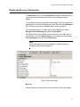
1
Broadcom Advanced Control Suite 3 User’s Guide 613-001247 Rev. A Copyright 2010 Allied Telesis, Inc. All rights reserved. No part of this publication may be reproduced without prior written permission from Allied Telesis, Inc. Microsoft and Internet Explorer are registered trademarks of Microsoft Corporation. Netscape Navigator is a registered trademark of Netscape Communications Corporation. All other product names, company names, logos or other designations mentioned herein are trademarks or registered trademarks of their respective owners. Allied Telesis, Inc. reserves the right to make changes in specifications and other information contained in this document without prior written notice. The information provided herein is subject to change without notice. In no event shall Allied Telesis, Inc. be liable for any incidental, special, indirect, or consequential damages whatsoever, including but not limited to lost profits, arising out of or related to this manual or the information contained herein, even if Allied Telesis, Inc. has been advised of, known, or should have known, the possibility of such damages. Contents Preface .............................................................................................................................................................. 7 Safety Symbols Used in this Document ............................................................................................................. 8 Where to Find Web-based Guides ..................................................................................................................... 9 Contacting Allied Telesis .................................................................................................................................. 10 Online Support ........................................................................................................................................... 10 Email and Telephone Support.................................................................................................................... 10 Returning Products .................................................................................................................................... 10 For Sales or Corporate Information............................................................................................................ 10 Warranty..................................................................................................................................................... 10 Management Software Updates................................................................................................................. 10 Chapter 1: Starting and Using BACS 3 ........................................................................................................ 11 Starting Broadcom Advanced Control Suite 3 .................................................................................................. 12 Using Broadcom Advanced Control Suite 3 ..................................................................................................... 14 Using the Interface ..................................................................................................................................... 14 Displaying Device Management Information.............................................................................................. 14 Configuring BACS User Interface Options ................................................................................................. 17 Setting User Interface Appearance ............................................................................................................ 17 Viewing Vital Signs..................................................................................................................................... 17 Viewing Driver Information ......................................................................................................................... 20 Displaying Resource Information...................................................................................................................... 21 Testing the Network ................................................................................................................................... 24 Running Diagnostic Tests .......................................................................................................................... 25 Analyzing Cables ....................................................................................................................................... 28 Setting Adapter Properties ......................................................................................................................... 30 Displaying Statistics.......................................................................................................................................... 38 General Statistics ....................................................................................................................................... 38 Chapter 2: Configuring Teaming .................................................................................................................. 43 Defining Team Types ....................................................................................................................................... 45 Smart Load Balance and Failover.............................................................................................................. 45 Link Aggregation (802.3ad)........................................................................................................................ 45 Generic Trunking (FEC/GEC)/802.3ad-Draft Static ................................................................................... 45 SLB (Auto-Fallback Disable) ...................................................................................................................... 45 Using the Broadcom Teaming Wizard.............................................................................................................. 47 Using the Expert Mode ..................................................................................................................................... 65 Creating a Team ........................................................................................................................................ 65 Modifying a Team....................................................................................................................................... 70 Displaying VLANs and Running VLAN Tests............................................................................................. 73 Configuring LiveLink................................................................................................................................... 74 Saving and Restoring the Configuration........................................................................................................... 78 Viewing BASP Statistics ................................................................................................................................... 79 3 Contents 4 Figures Figure 1: Device Management Page ....................................................................................................................................15 Figure 2: By Connection Page..............................................................................................................................................15 Figure 3: Team Management Page ......................................................................................................................................16 Figure 4: Device Management By Type Page ......................................................................................................................18 Figure 5: Driver Information Page.........................................................................................................................................20 Figure 6: Resources Page ....................................................................................................................................................21 Figure 7: Hardware Information Page...................................................................................................................................23 Figure 8: Network Test Page ................................................................................................................................................25 Figure 9: Diagnostic Tests Page...........................................................................................................................................26 Figure 10: Cable Analysis Page ...........................................................................................................................................29 Figure 11: Advanced Page ...................................................................................................................................................32 Figure 12: General Statistics Page .......................................................................................................................................39 Figure 13: Create a Team Path ............................................................................................................................................47 Figure 14: Edit Team Path....................................................................................................................................................48 Figure 15: Broadcom Teaming Wizard Page........................................................................................................................49 Figure 16: Creating/Modifying a Team: Team Name Page ..................................................................................................50 Figure 17: Creating/Modifying a Team: Team Type Page....................................................................................................51 Figure 18: Creating/Modifying a Team: Assigning Team Members Page ............................................................................52 Figure 19: Creating/Modifying a Team: Designating a Standby Member Page....................................................................53 Figure 20: Creating/Modifying a Team: Configuring LiveLink Page .....................................................................................54 Figure 21: Creating/Modifying a Team: Configuring LiveLink Page (continued 1) ...............................................................55 Figure 22: Creating/Modifying a Team: Configuring LiveLink Page (continued 2) ...............................................................56 Figure 23: Creating/Modifying a VLAN: Configure VLAN Support Page ..............................................................................57 Figure 24: Creating/Modifying a VLAN: Naming Page .........................................................................................................58 Figure 25: Creating/Modifying a VLAN: Tagging Page.........................................................................................................59 Figure 26: Creating/Modifying a VLAN: Tag Value Page .....................................................................................................60 Figure 27: Creating/Modifying a VLAN: Additional VLANs Page..........................................................................................61 Figure 28: Congratulations! Page .........................................................................................................................................62 Figure 29: Broadcom Teaming Wizard: Commit Changes Page..........................................................................................63 Figure 30: Team Properties Page.........................................................................................................................................64 Figure 31: Creating A Team Path .........................................................................................................................................66 Figure 32: Manage Teams Page: Create Team Tab ............................................................................................................66 Figure 33: Manage Load Balance Members Window...........................................................................................................67 Figure 34: Editing a Team Path ............................................................................................................................................70 Figure 35: Manage Teams Page: Edit Team Tab.................................................................................................................71 Figure 36: Manage VLAN(s) Page........................................................................................................................................73 Figure 37: Manage Teams Page: Edit Teams Tab...............................................................................................................76 Figure 38: General Page ......................................................................................................................................................80 5 Figures 6 Preface This guide contains instructions on how to install and use the Broadcom Advanced Control Suite 3 for Ethernet Network adapters. The Broadcom Advanced Control Suite 3 (BACS 3) is an integrated utility that provides useful information about each network adapter that is installed in your system. BACS 3 also enables you to perform detailed tests, diagnostics, and analyses on each adapter, as well as to display and modify property values and display traffic statistics for each adapter. The Broadcom Advanced Server Program (BASP), which runs within Broadcom Advanced Control Suite 3, is used to configure teams for load balancing, fault tolerance, and Virtual Local Area Networks (VLANs). BASP functionality is available only on systems that use at least one Broadcom network adapter. The Preface contains the following sections: “Safety Symbols Used in this Document” on page 8 “Where to Find Web-based Guides” on page 9 “Contacting Allied Telesis” on page 10 “Management Software Updates” on page 10 7 Preface Safety Symbols Used in this Document This document uses the safety symbols defined in Table 1. Table 1. Safety Symbols Symbol 8 Meaning Description Caution Performing or omitting a specific action may result in equipment damage or loss of data. Warning Performing or omitting a specific action may result in electrical shock. Broadcom Advanced Control Suite 3 User’s Guide Where to Find Web-based Guides The installation and user guides for all Allied Telesis products are available in portable document format (PDF) on our web site at www.alliedtelesis.com/support/software. You can view the documents online or download them onto a local workstation or server. 9 Preface Contacting Allied Telesis This section provides Allied Telesis contact information for technical support as well as sales or corporate information. Online Support You can request technical support online by accessing the Allied Telesis Knowledge Base: www.alliedtelesis.com/support/kb.aspx. You can use the Knowledge Base to submit questions to our technical support staff and review answers to previously asked questions. Email and Telephone Support For Technical Support via email or telephone, refer to the Support section of the Allied Telesis web site: www.alliedtelesis.com/support. Returning Products Products for return or repair must first be assigned a return materials authorization (RMA) number. A product sent to Allied Telesis without an RMA number will be returned to the sender at the sender’s expense. For instructions on how to obtain an RMA number, go to the Support section on our web site at www.alliedtelesis.com/support/rma.aspx. For Sales or Corporate Information You can contact Allied Telesis for sales or corporate information through our web site at http://www.alliedtelesis.com/purchase. Warranty For hardware warranty information, refer to the Allied Telesis web site: www.alliedtelesis.com/support/warranty. Management Software Updates New releases of management software for our managed products are available from either of the following Internet sites: Allied Telesis web site: www.alliedtelesis.com/support/software Allied Telesis FTP server: ftp://ftp.alliedtelesis.com If you prefer to download new software from the Allied Telesis FTP server from your workstation’s command prompt, you will need FTP client software and you must log in to the server. Enter “anonymous” for the user name and your email address for the password. 10 Chapter 1 Starting and Using BACS 3 This chapter provides detailed information about the minimum and recommended .NET Framework versions for BACS3. In addition, this chapter describes how to set the BACs software. This chapter contains the following sections: “Starting Broadcom Advanced Control Suite 3” on page 12 “Using Broadcom Advanced Control Suite 3” on page 14 “Displaying Resource Information” on page 21 “Displaying Statistics” on page 38 11 Chapter 1: Starting and Using BACS 3 Starting Broadcom Advanced Control Suite 3 Microsoft .NET Framework 2.0 includes the runtime and associated files needed to run BACS 3, and must be installed on your system in order for BACS 3 to operate. For information on the minimum and recommended .NET Framework versions for your operating system, see Table 1. Note Starting BACS 3 without .NET Framework (version 2.0 or above) installed on your system results in an error. Note Long startup times for BACS 3 may be caused by a limitation of .NET Framework 2.0, as described in Microsoft Knowledge Base article KB936707. To improve the startup time of BACS 3, apply .NET Framework 2.0 SP1 (or the appropriate version for your OS as shown in the Recommended column of Table 1) and reboot your system. Note For optimal performance of BACS 3, Broadcom recommends .NET Framework 2.0 SP1, .NET Framework 3.0 SP1, or .NET Framework 3.5, depending on your operating system. Table 1. .NET Framework Versions for BACS 3 Minimum Required Recommended Operating System Version 12 How to Obtain Version How to Obtain Windows 2000 Server .NET 2.0 Download from Microsoft .NET 2.0 SP1 Download from Microsoft Windows Server 2003 .NET 2.0 Download from Microsoft .NET 2.0 SP1 Download from Microsoft Windows Server 2003 R2 .NET 2.0 Included in OS package, but by default, not included during installation .NET 2.0 SP1 Download from Microsoft Broadcom Advanced Control Suite 3 User’s Guide Table 1. .NET Framework Versions for BACS 3 (Continued) Minimum Required Recommended Operating System Version How to Obtain Version How to Obtain Windows Vista .NET 2.0 Included in .NET 3.0 which is included during OS installation .NET 2.0 SP1 Download Vista SP1 from Microsoft which includes .NET 2.0 SP1 Windows Server 2008 .NET 2.0 Included in .NET 2.0 SP1, which is included during OS installation .NET 2.0 SP1 Included in OS package 13 Chapter 1: Starting and Using BACS 3 Using Broadcom Advanced Control Suite 3 To start BACS 3, click Broadcom Control Suite 3 in the Control Panel. Click the tab that provides the information of interest such as to perform a desired test, diagnostic, analysis, or set adapter properties. To create a team, see Chapter 2, “Configuring Teaming” on page 43. Using the Interface BACS 3 features a context-sensitive interface. When an item is selected in the Explorer View, such as an adapter, driver, team, or VLAN, the interface changes to display the information and options available for the selected item. Certain tabs, menu options, and device information are only available based on the types of devices installed or the item selected in the interface. Two buttons at the bottom of the interface control what you want to manage. Click the Device Management button to manage the connected devices (see “Displaying Device Management Information,” next). Or, click the Team Management button to create and manage teams (see “Team Management” on page 16). Displaying Device Management Information The Device Management pane lists the devices that can be viewed, analyzed, tested, or adjusted by BACS 3. When an item is selected in the Device Management pane, the tabs showing the information and options that are available for the item appear. Because the BACS 3 interface is context-sensitive, only the information that applies to the selected item can be displayed or adjusted. The items in Device Management can be listed by type or by connection. To list items in Device Management by type, do the following: At the top of the Device Management pane, click By Type. The Device Management Page is displayed. See Figure 1 on page 15. A single hardware device may use several different drivers. Device Management breaks each item into separate categories. 14 Network Adapters. Lists the available NDIS client adapters. Broadcom Advanced Control Suite 3 User’s Guide Figure 1. Device Management Page To list items in Device Management by connection, do the following: At the top of the Device Management pane, click By Connection. The By Connection Page is displayed. See Figure 2 on page 15. The Connection View lists the server and client devices in a parent/child hierarchy, which makes it easier to see the relationships between the adapters. Just as in the Device Management pane, selecting items in the Connection View shows the options available for that item. Figure 2. By Connection Page 15 Chapter 1: Starting and Using BACS 3 Device Icons The icon next to each device in the Device Management pane shows its status. An icon next to a device name that appears normal means the device is connected and working. Two additional states may occur: X. A red "X" that appears on the device's icon indicates the device is currently not connected to the network. Greyed out. A device icon that appears greyed out indicates the device is currently disabled. Team Management The Team Management pane displays how network adapters have been grouped together to function as a team, or a virtual LAN (VLAN). The pane separates the adapters that have been grouped into a team from those that remain unassigned. See Figure 3 for an example of the Team Management Page. Team Management becomes available only when more than one Allied Telesis or Broadcom-based network adapters are installed and available to be grouped into a team. In addition, Team Management is only available with server-class adapters. To create or edit teams, see Chapter 2, “Configuring Teaming” on page 43. Figure 3. Team Management Page 16 Broadcom Advanced Control Suite 3 User’s Guide Configuring BACS User Interface Options This section describes how to enable and disable the BACS Tray icon. After the program is installed, BACS 3 places an icon in the Windows taskbar. Use the Options window to turn this icon on or off. To enable or disable the BACS tray icon, do the following: 1. From the Tools menu, select Options. 2. In the Options window, select General. 3. Select or clear Enable Tray Icon. The option is enabled by default. 4. Click OK. Setting User Interface Appearance By default, the BACS User Interface is set to x, y, and z. You can customize the appearance of the BACS 3 interface. In addition, you can reset the user interface to its default values. To change the interface appearance, do the following: 1. From the Tools menu, select Options. 2. In the Options window, select Appearance. 3. Choose the appearance settings. Click Apply to set changes. Click OK to set changes and close the Options window. To reset the interface to the default appearance, do the following: 1. From the Tools menu, select Options. 2. In the Options window, select General. 3. Click Restore Default. 4. Close and then restart BACS 3. Viewing Vital Signs The Vital Signs section of the Information tab has useful information about the network adapters that are installed in your system, such as the link status of the adapter and general network connectivity. To view Vital Signs information for any installed network adapter, click the name of the adapter listed in the Device Management pane, then click the Information tab. The Device Management By Type Page is displayed. See Figure 4 on page 18. If the Information tab is not visible, then do the following. From the View menu, select Navigate, Device Management, and then Information. 17 Chapter 1: Starting and Using BACS 3 If the Vital Signs section within the Information tab is not visible, do the following. From the Context View tab on the right side of the window, select Information. Then, select Vital Signs. Note Information about Allied Telesis or Broadcom-based network adapters may be more comprehensive than information about network adapters made by other vendors. Note Some information may not be available for all Allied Telesis or Broadcom-based network adapters. Figure 4. Device Management By Type Page MAC Address A physical MAC (media access control) address that is assigned to the adapter by the manufacturer. The physical address is never all 0s. Permanent MAC Address The unique hardware address assigned to the network adapter. IP Address The network address associated with the adapter. If the IP address is all 0s, the associated driver has not been bound with the Internet Protocol (IP). 18 Broadcom Advanced Control Suite 3 User’s Guide Link Status The Link Status indicates the status of the network link. There are two states: Up. A link is established. Down. A link is not established. Duplex The adapter is operating in the indicated duplex mode. Speed The link speed of the adapter in megabits per second. Offload Capabilities The offload capabilities supported by the adapter. This information is only available for Allied Telesis AT-2973 adapters. LSO. Large Send Offload (LSO) prevents an upper level protocol such as TCP from breaking a large data packet into a series of smaller packets with headers appended to them. CO. Checksum Offload (CO) allows the TCP/IP/UDP checksums for send and receive traffic to be calculated by the adapter hardware rather than by the host CPU. LiveLink IP Address The network address of the LiveLink enabled adapter. Local Connection Identifies the module to which the blade server is attached. There are 3 possible states: Chassis SW. Indicates the chassis switch module Chassis PHY. Indicates the pass-through module None. Indicates that no modules are attached BASP State Information about the status of the BASP application. This information is displayed only when there is a team configured (see Chapter 2, “Configuring Teaming” on page 43). 19 Chapter 1: Starting and Using BACS 3 Viewing Driver Information The Driver Information section of the Information tab displays data about the driver for the selected network adapter. To view Driver Information for any installed network adapter, click the name of the adapter listed in the Device Management pane, then click the Information tab. The Driver Information Page is displayed. See Figure 5. If the Information tab is not visible, then from the View menu, select Navigate, then Device Management, and then Information. If the Driver Information section within the Information tab is not visible, then from the Context View tab on the right side of the window, select Information and then select Driver. Figure 5. Driver Information Page Driver Status Indicates the status of the adapter driver. There are 3 possible states: Loaded. Indicates the normal operating mode. The adapter driver has been loaded by Windows and is functioning. Not Loaded. Indicates the driver associated with the adapter has not been loaded by Windows. Information Not Available. Indicates the value is not obtainable from the driver that is associated with the adapter. Driver Name Indicates the file name of the adapter driver. Driver Version Indicates the current version of the adapter driver. Driver Date Indicates the creation date of the adapter driver. 20 Broadcom Advanced Control Suite 3 User’s Guide Displaying Resource Information The Resources section of the Information tab displays information about connections and other essential functions for the selected network adapter. To view Resources for any installed network adapter, click the name of the adapter listed in the Device Management pane, then click the Information tab. The Resources Page is displayed. See Figure 6 on page 21. If the Information tab is not visible, then from the View menu, select Navigate, Device Management, and then Information. If the Resources section within the Information tab is not visible, then do the following. From the Context View tab on the right side of the window, select Information, and then select Resources. Note Some information may not be available for all Allied Telesis or Broadcom-based network adapters. Figure 6. Resources Page Bus Type Indicates the type of input/output (I/O) interconnect used by the adapter. 21 Chapter 1: Starting and Using BACS 3 Slot No Indicates the slot number on the system board occupied by the adapter. This item is not available for PCI Express type adapters. Bus Speed (MHz) Indicates the bus clock signal frequency used by the adapter. This item is not available for PCI Express type adapters. Bus Width (bit) Indicates the number of bits that the bus can transfer at a single time to and from the adapter. This item is not available for PCI Express type adapters. Bus No Indicates the number of the bus where the adapter is installed. Device No Indicates the number assigned to the adapter by the operating system. Function No Indicates the port number of the adapter. For a single-port adapter, the function number is 0. For a two-port adapter, the function number for the first port is 0, and the function number for the second port is 1. Interrupt Request Indicates the interrupt line number that is associated with the adapter. Valid numbers range from 2 to 25. Memory Address Indicates the memory mapped address that is assigned to the adapter. Note The value of the Memory Address parameter cannot be 0. Viewing Hardware Information The Hardware section of the Information tab displays information about the hardware settings for the selected network adapter. 22 Broadcom Advanced Control Suite 3 User’s Guide To view Hardware for any installed network adapter, click the name of the adapter listed in the Device Management pane, then click the Information tab. The Hardware Information Page is displayed. See Figure 7. If the Information tab is not visible, then from the View menu, select Navigate, Device Management, and Information. If the Hardware section within the Information tab is not visible, then from the Context View tab on the right side of the window, select Information and Hardware. Note Some information may not be available for all Allied Telesis or Broadcom-based network adapters. Figure 7. Hardware Information Page ASIC Version Indicates the chip version of the Broadcom adapter. This information is not available for adapters made by other vendors. Management Firmware Indicates the firmware version installed on the system. Vendor ID Indicates the vendor ID. Device ID Indicates the adapter ID. 23 Chapter 1: Starting and Using BACS 3 Subsystem Vendor ID Indicates the subsystem vendor ID. Subsystem ID Indicates the subsystem ID. Testing the Network The Network Test option on the Diagnostics tab lets you verify IP network connectivity. This test verifies if the driver is installed correctly and tests connectivity to a gateway or other specified IP address on the same subnet. The network test uses TCP/IP to send ICMP packets to remote systems, then waits for a response. If a gateway is configured, the test automatically sends packets to that system. If a gateway is not configured or if the gateway is unreachable, the test prompts for a destination IP address. Note The network test option is not available on adapters that are grouped into a team. For information about teaming, see Chapter 2, “Configuring Teaming” on page 43. To run the network test, do the following: 1. Click the name of the adapter to test in the Device Management pane. 2. Click the Diagnostics tab. If the Diagnostics tab is not visible, then from the View menu, select Navigate, Device Management, and then Diagnostics. 3. From the Select a test to run list, select Network Test. If the Network Test option is not available, then from the Context View tab on the right side of the window, select Diagnostics and then select Network Test. The Network Test Page is displayed. See Figure 8 on page 25. 4. To change the destination IP address, select IP address to ping, then click the browse button (...). In the Network Test window, enter a Destination IP address, then click OK. 24 Broadcom Advanced Control Suite 3 User’s Guide 5. Click Run. The results of the network test are displayed in the Result field of Figure 8. Figure 8. Network Test Page Running Diagnostic Tests The Diagnostic Tests option on the Diagnostics tab lets you check the state of the physical components on a Allied Telesis or Broadcom-based network adapter. You can trigger the tests manually, or choose to have BACS 3 continuously perform them. If the test are performed continuously, then the number of passes and fails in the Status field for each test increments every time the tests are performed. For example, if a test is performed four times and there are no fails, the value in the Status field for that test is 4/0. However, if there were 3 passes and 1 fail, the value in the Status field is 3/1. Note You must have administrator privileges to run diagnostic tests. Note The network connection is temporarily lost while these tests are running. To run the diagnostic tests, do the following: 1. Click the name of the adapter that you want to test in the Device Management pane. 2. Click the Diagnostics tab. If the Diagnostics tab is not visible, then from the View menu, select Navigate, then Device Management, and Diagnostics. 25 Chapter 1: Starting and Using BACS 3 3. From the Select a test to run list, select Diagnostic Tests. If the Diagnostic Tests option is not available, then from the Context View tab on the right side of the window, select Diagnostics and then select Diagnostic Tests. The Diagnostics Test Page is displayed. See Figure 9 on page 26. 4. Select the diagnostic tests you want to run. Click Select All to select all tests or Clear All to clear all test selections. 5. Click Run. 6. In the error message window that warns of the network connection being temporarily interrupted, click Yes. The results are displayed in the Status field for each test. To run the diagnostic tests continuously, do the following: 1. Click the name of the adapter to test in the Device Management pane. 2. Click the Diagnostics tab. If the Diagnostics tab is not visible, then from the View menu, select Navigate, then Device Management, and then Diagnostics. 3. From the Select a test to run list, select Diagnostic Tests. If the Diagnostic Tests option is not available, then from the Context View tab on the right side of the window, select Diagnostics and then select Diagnostic Tests. The Diagnostics Test Page is displayed. See Figure 9. Figure 9. Diagnostic Tests Page 4. Select the diagnostic tests you want to run. Click Select All to select all tests or Clear All to clear all test selections. 5. Select Run Continuously. 6. Click Run. 26 Broadcom Advanced Control Suite 3 User’s Guide 7. In the error message window that warns of the network connection being temporarily interrupted, click Yes. The diagnostic tests run continuously and the Status field for each test displays the accumulated total of passes and failures. 8. To stop the continuous testing, click Abort. Control Registers This test verifies the read and write capabilities of the network adapter registers by writing various values to the registers and verifying the results. The adapter driver uses these registers to perform network functions such as sending and receiving information. A test failure indicates that the adapter may not be working properly. MII Registers This test verifies the read and write capabilities of the registers of the physical layer (PHY). The physical layer is used to control the electrical signals on the wire and to configure network speeds such as 1000 Mbit/s. EEPROM This test verifies the content of the electrically erasable programmable read-only memory (EEPROM) by reading a portion of the EEPROM and computing the checksum. The test fails if the computed checksum is different from the checksum stored in the EEPROM. An EEPROM image upgrade does not require a code change for this test. Internal Memory This test verifies that the internal memory of the adapter is functioning properly. The test writes patterned values to the memory and reads back the results. The test fails if an erroneous value is read back. The adapter cannot function if its internal memory is not functioning properly. On-Chip CPU This test verifies the operation of the internal CPUs in the adapter. Interrupt This test verifies that the Network Device Driver Interface Specification (NDIS) driver is able to receive interrupts from the adapter. Loopback MAC and Loopback PHY These tests verify that the NDIS driver is able to send packets to and receive packets from the adapter. 27 Chapter 1: Starting and Using BACS 3 Test LED This test causes all of the port LEDs to blink 5 times for the purpose of identifying the adapter. Analyzing Cables The Cable Analysis option on the Diagnostics tab lets you monitor the conditions of each wire pair in an Ethernet Category 5 cable connection within an Ethernet network. The analysis measures the cable quality and compares it against the IEEE 802.3ab specification for compliance. Note You must have administrator privileges to run the cable analysis test. Note The network connection is temporarily lost during an analysis. Note For Allied Telesis or Broadcom-based adapters, the cable analysis test can only run for gigabit link speed connections and when there is no connection. Note This option is not available for all Allied Telesis fiber network adapters. To run a cable analysis, do the following: 1. Connect the cable to a port on a switch where the port is set to Auto and the Speed & Duplex driver settings are also set to Auto. 2. Click the name of the adapter to test in the Device Management pane. 3. Click the Diagnostics tab. If the Diagnostics tab is not visible, then from the View menu, select Navigate, Device Management, and then Diagnostics. The Cable Analysis Page is displayed. See Figure 10. 4. From the Select a test to run list, select Cable Analysis. If the Cable Analysis option is not available, then from the Context View tab on the right side of the window, select Diagnostics and then select Cable Analysis. 5. Click Run. 28 Broadcom Advanced Control Suite 3 User’s Guide 6. In the error message window that warns of the network connection being temporarily interrupted, click Yes. Figure 10. Cable Analysis Page Distance The valid cable length in meters (except when the Noise result is returned). 29 Chapter 1: Starting and Using BACS 3 Status The result of the analysis for the indicated pair can be one of the following: Good. Good cable/PCB signal paths, but no gigabit link. Crossed. Pin short or crosstalk along two or more cable/PCB signal paths. Open. One or both pins are open for a twisted pair. Short. Two pins from the same twisted pair are shorted together. Noise. Persistent noise present (most likely caused by Forced 10/ 100). GB Link. Gigabit link is up and running. N/A. Algorithm failed to reach a conclusion. Link Indicates the link connection speed and mode. Status The status after the test is run, either completed or failed. There are several factors that could affect the test results: Setting Adapter Properties Link partner. Various switch and hub manufacturers implement different PHYs. Some PHYs are not IEEE compliant. Cable quality. Category 3, 4, 5, and 6 may affect the test results. Electrical interference. The testing environment may affect the test results. Selecting Options on the Configurations tab allows you to view and change the values of the available properties of the selected adapter. The potentially available properties and their respective settings are described in this section. Note You must have administrator privileges to change the values for a property. Note The list of available properties for your particular adapter may be different. In addition, some properties may not be available for all Allied Telesis or Broadcom-based network adapters. 30 Broadcom Advanced Control Suite 3 User’s Guide To set adapter properties, do the following: 1. Click the name of the adapter in the Device Management pane. 2. Click the Configurations tab. If the Configurations tab is not visible, then from the View menu, select Navigate, Device Management, and Configurations. 3. From the Advanced section, select the property you want to set. If the Advanced section is not available, then from the Context View tab on the right side of the window, select Configurations and then select Advanced. The Advanced Page is displayed. See Figure 11 on page 32. 4. To change the value of a property, select an item from the property's list or type a new value, as appropriate (selection options are different for different properties). 5. Click Apply to confirm the changes to all properties. Click Reset to return the properties to their original values. 31 Chapter 1: Starting and Using BACS 3 Figure 11. Advanced Page 802.1p QOS Enables the quality of service (QoS) feature, which is an Institute of Electrical and Electronics Engineering (IEEE) specification that treats different types of network traffic diversely to ensure required levels or reliability and latency according to the type of traffic. This property is disabled by default. Unless the network infrastructure supports QoS, do not enable this property. Otherwise, problems may occur. Ethernet@Wirespeed Enables a Gigabit Ethernet adapter to establish a link at a lower speed when only two pairs of wires are available in the cabling plant. The default setting for this property is Enabled. 32 Broadcom Advanced Control Suite 3 User’s Guide Flow Control Enables or disables the receipt or transmission of PAUSE frames. PAUSE frames allow the network adapter and a switch to control the transmit rate. The side that is receiving the PAUSE frame momentarily stops transmitting. Select one of the following: Auto (default). PAUSE frame receipt and transmission are optimized. Disable. PAUSE frame receipt and transmission are disabled. Rx PAUSE. PAUSE frame receipt is enabled. Rx/Tx PAUSE. PAUSE frame receipt and transmission are enabled. Tx PAUSE. PAUSE frame transmission is enabled. IPv4 Checksum Offload Normally, the checksum function is computed by the protocol stack. When you select one of the Checksum Offload property values (other than None), the checksum can be computed by the network adapter. Select one of the following: Rx Enabled. Enables receive TCP/IP/UDP checksum offload. Tx Enabled. Enables transmit TCP/IP/UDP checksum offload. Tx/Rx Enabled (default). Enables transmit and receive TCP/IP/UDP checksum offload. None. Disables checksum offload. IPv4 Large Send Offload Normally, the TCP segmentation is done by the protocol stack. When you enable the Large Send Offload property, the TCP segmentation can be done by the network adapter. The default setting for this property is Enabled. This property is only available for Broadcom NetXtreme II adapters. Jumbo MTU Enables the network adapter to transmit and receive oversized Ethernet frames that are greater than 1514 bytes, but less than or equal to 9000 bytes in length. This property requires the presence of a switch that is able to process jumbo frames. This property is only available for Broadcom NetXtreme II adapters. Frame size is set at 1500 bytes by default. To increase the size of the received frames, raise the byte quantity in 500-byte increments. 33 Chapter 1: Starting and Using BACS 3 LSO & Jumbo Frames Enables the network adapter to transmit and receive oversized Ethernet frames that are greater than 1514 bytes, but less than 9000 bytes in length. This property requires the presence of a switch that is able to process Jumbo frames. This information is available for some Broadcom NetXtreme adapters. Frame size is set at 1500 bytes by default by selecting the LSO Enabled, Jumbo Off option. Note Jumbo Frames and Large Send Offload (LSO) are mutuallyexclusive properties. Normally, the TCP segmentation is done by the protocol stack. When you enable the Large Send Offload (LSO) property, the TCP segmentation can be done by the network adapter. Select one of the following: Both Disabled. LSO & Jumbo frames are both disabled. LSO Enabled, Jumbo Off (default). LSO enabled and jumbo frames disabled. LSO Off, Jumbo 3000. Frame size of 3000 bytes and LSO off. LSO Off, Jumbo 4500. Frame size of 4500 bytes and LSO off. LSO Off, Jumbo 6000. Frame size of 6000 bytes and LSO off. LSO Off, Jumbo 7500. Frame size of 7500 bytes and LSO off. LSO Off, Jumbo 9000. Frame size of 9000 bytes and LSO off. Locally Administered Address The Locally Administered Address is a user-defined MAC address that is used in place of the MAC address originally assigned to the network adapter. Every adapter in the network must have its own unique MAC address. This locally administered address consists of a 12-digit hexadecimal number. Select one of the following: 34 Value. Assigns a unique node address for the adapter. Not Present (default). Uses the factory-assigned node address on the adapter. Broadcom Advanced Control Suite 3 User’s Guide The appropriate assigned ranges and exceptions for the locally administered address include the following: The range is 00:00:00:00:00:01 to FF:FF:FF:FF:FF:FD. Do not use a multicast address (least significant bit of the high byte = 1). Do not use all 0s or all Fs. Receive Side Scaling Allows configuring network load balancing across multiple CPUs. The default setting for this property is Enabled. Speed & Duplex The Speed & Duplex property sets the connection speed and mode to that of the network. Note that Full-Duplex mode allows the adapter to transmit and receive network data simultaneously. 10 Mb Full. Sets the speed at 10 Mbit/s and the mode to Full-Duplex. 10 Mb Half. Sets the speed at 10 Mbit/s and the mode to Half-Duplex. 100 Mb Full. Sets the speed at 100 Mbit/s and the mode to FullDuplex. 100 Mb Half. Sets the speed at 100 Mbit/s and the mode to HalfDuplex. 1 Gb Full Auto. Sets the speed to Auto-Negotiate at 1000 Mb FullDuplex mode only. Auto (default). Sets the speed and mode for optimum network connection (recommended). Note Auto is the recommended setting. This setting allows the network adapter to dynamically detect the line speed of the network. Whenever the network capability changes, the network adapter automatically detects and adjusts to the new line speed and duplex mode. A speed of 1 Gbit/s is enabled by selecting Auto, when that speed is supported. Note 1 Gb Full Auto must be attached to a link partner that is also capable of a 1 Gb connection. Since the connection is limited to a 1 Gb connection only, the Ethernet@Wirespeed feature will be disabled. If the link partner supports a 1 Gb connection only, the Wake on LAN feature may not work. Additionally, management traffic (IPMI or UMP) in the absence of an operating system may also be affected. 35 Chapter 1: Starting and Using BACS 3 Note 10 Mb Half and 100 Mb Half settings force the network adapter to connect to the network in Half-Duplex mode. Note that the network adapter may not function if the network is not configured to operate at the same mode. Note 10 Mb Full and 100 Mb Full settings force the network adapter to connect to the network in Full-Duplex mode. The network adapter may not function if the network is not configured to operate at the same mode. Speed & Duplex (SerDes) This section displays the speed and duplex properties for the adapter. Select one of the following: 1 Gb Full. Forces the speed to 1 Gb Full based on a matching setting for its link partner. Auto (default). Sets the speed to auto-negotiate with its link partner at the highest matching speed. Auto with 1Gb Fallback Full. Sets the speed to auto-negotiate with its link partner, but if the attached link partner is forced at 1 Gbit/s, it reverts to this mode. Hardware Default. Sets the speed to negotiate according to the setting specified by the manufacturer. See the manufacturer’s documentation for more information. Wake Up Capabilities Enables the network adapter to wake up from a low-power mode when it receives a network wake-up frame. Two types of wake-up frames are possible: Magic Packet™ and Wake Up Frame. This property is only available for Broadcom NetXtreme adapters. Select one of the following: 36 Both (default). Selects both Magic Packet and Wake Up Frame as wake-up frames. Magic Packet. Selects Magic Packet as the wake-up frame. None. Selects no wake-up frame. Wake Up Frame. Selects Wake Up Frame as the wake-up frame and allows the network adapter to wake the system when an event such as a ping or an Address Resolution Protocol (ARP) request is received. This option works in conjunction with the operating system power mode saving and does not work if the Power Save setting does not enable WOL. Broadcom Advanced Control Suite 3 User’s Guide WOL Speed Sets the speed at which the network adapter connects to the network while the network adapter is in Wake on LAN mode. By default, the WOL Speed property is set to Auto. This property is only available for Broadcom NetXtreme adapters. 10 Mb. Sets the speed to 10 Mbit/s. This is the network speed when the system is in a standby mode awaiting a wake-up frame. 100 Mb. Sets the speed to 100 Mbit/s. Auto (default). Sets the speed for optimum network connection. Note Wake on LAN is supported at 10 Mbit/s or 100 Mbit/s. Note Wake on LAN is supported on only one adapter in the system at a time. Interrupt Moderation Enables adaptive interrupt coalescing, which limits the rate of interrupt to the CPU during packet transmission and packet reception. The disabled option allows one interrupt for every packet transmission and packet reception. Number of Receive Descriptors The number of receive descriptors with options of Default, Minimum, and Maximum. Receive descriptors are data segments that allow the network adapter to allocate receive packets to memory. Number of Transmit Descriptors The number of transmit descriptors with value options from 100 to 600 with 200 being the default value. Transmit descriptors are data segments that allow the network adapter to monitor transmit packets in the system memory. RSS Queues Allows configuring RSS queues from 1 to 4. Options are RSS 1 Queue, RSS 2 Queue, and RSS 4 Queue. 37 Chapter 1: Starting and Using BACS 3 Displaying Statistics The information provided on the Statistics tab allows you to display traffic statistics for Allied Telesis, Broadcom-based network adapters, and network adapters made by other vendors. Statistical information and coverage are more comprehensive for Allied Telesis and Broadcom-based adapters. To display Statistics information for any installed network adapter, click the name of the adapter listed in the Device Management pane, then click the Statistics tab. If the Statistics tab is not visible, then from the View menu, select Navigate, then Device Management, and then Statistics. The General Page is displayed. See Figure 12 on page 39. If any of the sections described below is not visible, then from the Context View tab on the right side of the window, select Statistics and then select the name of the missing section. Click Refresh to get the most recent values for each statistic. Click Reset to change all values to zero. Note Team statistics are not compiled for a Allied Telesis or Broadcombased network adapter if it is disabled. Note Some statistics may not be available for all Allied Telesis or Broadcom-based network adapters. General Statistics This section describes the parameters in the General Statistics Page. See Figure 12 on page 39. Frames Tx OK A count of the frames that were successfully transmitted. This counter is incremented when the transmit status is reported as Transmit OK. Frames Rx OK A count of the frames that were successfully received. This does not include frames received with frame-too-long, frame check sequence (FCS), length, or alignment errors, nor frames lost due to internal MAC sublayer errors. This counter is incremented when the receive status is reported as Receive OK. 38 Broadcom Advanced Control Suite 3 User’s Guide Figure 12. General Statistics Page Directed Frames Tx A count of directed data frames that were successfully transmitted. Multicast Frames Tx A count of frames that were successfully transmitted (as indicated by the status value Transmit OK) to a group destination address other than a broadcast address. Broadcast Frames Tx A count of frames that were successfully transmitted (as indicated by the transmit status Transmit OK) to the broadcast address. Frames 39 Chapter 1: Starting and Using BACS 3 transmitted to multicast addresses are not broadcast frames and are excluded. Directed Frames Rx A count of directed data frames that were successfully received. Multicast Frames Rx A count of frames that were successfully received and are directed to an active nonbroadcast group address. This does not include frames received with frame-too-long, FCS, length, or alignment errors, nor frames lost because of internal MAC sublayer errors. This counter is incremented as indicated by the Receive OK status. Broadcast Frames Rx A count of frames that were successfully received and are directed to a broadcast group address. This count does not include frames received with frame-too-long, FCS, length, or alignment errors, nor frames lost because of internal MAC sublayer errors. This counter is incremented as indicated by the Receive OK status. Frames Rx with CRC Error The number of frames received with CRC errors. IEEE 802.3 Statistics This section describes the parameters in the IEEE 802.3 Statistics portion of the General Statistics Page appears in Figure 12 on page 39. Frames Rx with Alignment Error. A count of the frames that were not an integral number of octets in length and do not pass the FCS check. This counter is incremented when the receive status is reported as Alignment Error. Frames Tx with one Collision. A count of the frames that were involved in a single collision and were subsequently transmitted successfully. This counter is incremented when the result of a transmission is reported as Transmit OK and the attempt value is 2. Frames Tx with more than one Collision. A count of the frames that were involved in more than one collision and were subsequently transmitted successfully. This counter is incremented when the transmit status is reported as Transmit OK and the value of the attempts variable is greater than 2 and less than or equal to the attempt limit. 40 Broadcom Advanced Control Suite 3 User’s Guide Frames Tx after Deferral. A count of the frames that were delayed being transmitted on the first attempt because the medium was busy. The frames involved in any collision are not counted. Custom Statistics This section describes the Custom Statistics portion of the General Statistics page which appears in Figure 12 on page 39. Note Custom statistics are available only for an enabled Allied Telesis or Broadcom-based network adapter. Out of Recv. Buffer. The number of times the adapter ran out of Receive Buffer Descriptors. This information is only available for Broadcom NetXtreme II adapters. Frames size less than 64-byte with bad FCS. The number of frames with a size less than 64 bytes with bad FCS. MAC Rx w/ Pause Command and Length = 0. MAC control frames with the pause command and a length equal to 0. MAC Rx w/ Pause Command and Length greater than 0. MAC control frames with the pause command and a length greater than 0. MAC Rx w/ no Pause Command. MAC control frames with no pause command. MAC Sent X-on. MAC Transmit with X-on was on. MAC Sent X-off. MAC Transmit with X-on was off. Large Send Offload Transmit Requests. The number of times the adapter was requested to transmit a packet performing TCP segmentation. Total Offload TCP Connections. The total number of off-loaded TCP connections. 41 Chapter 1: Starting and Using BACS 3 42 Chapter 2 Configuring Teaming The teaming function allows you to group any available network adapters together to function as a team. Teaming is a method of creating a virtual NIC which is a group of multiple adapters that functions as a single adapter. The benefit of this approach is that it enables load balancing and failover. Teaming is done through the Broadcom Advanced Server Program (BASP) software. For a comprehensive description of the technology and implementation considerations of the teaming software, refer to the "Broadcom Gigabit Ethernet Teaming Services" section of your network adapter user guide. Teaming can be accomplished by using the Broadcom Teaming Wizard or the Expert Mode. Both methods are described in this chapter. This chapter contains the following sections: “Defining Team Types” on page 45 “Using the Broadcom Teaming Wizard” on page 47 “Using the Expert Mode” on page 65 “Saving and Restoring the Configuration” on page 78 “Viewing BASP Statistics” on page 79 Note For further information regarding teaming protocols, search for "Teaming" in your network adapter user guide. Note For information about configuring Live Link, see “Using the Expert Mode” on page 65. If you do not enable LiveLink™ when configuring teams, Allied Telesis recommends disabling Spanning Tree Protocol (STP) at the switch. This minimizes the downtime due to spanning tree loop determination when failing over. LiveLink mitigates such issues. Note BASP is available only if a system has one or more Allied Telesis or Broadcom-based network adapters installed. 43 Chapter 2: Configuring Teaming Note The TCP Offload Engine (TOE), Large Send Offload (LSO), and Checksum Offload properties are enabled for a team only when all of the members support and are configured for the feature. Note You must have administrator privileges to create or modify a team. Note The load balance algorithm in a team environment in which members are connected at different speeds favors members connected with a Gigabit Ethernet link over members connected at lower speed links (100 Mbps or 10 Mbps) until a threshold is met. This is normal behavior. Note Wake on LAN (WOL) is a feature that allows a system to be awakened from a sleep state by the arrival of a specific packet over the Ethernet interface. Because a virtual adapter is implemented as a software-only device, it lacks the hardware features to implement WOL and cannot be enabled to wake the system from a sleeping state via the virtual adapter. The physical adapters, however, support this property, even when the adapter is part of a team. Note The use of any form of teaming— Smart Load Balancing, Generic Trunking, or Link Aggregation— with an iSCSI boot device is not supported. However, teaming can still be configured on other devices in the system. 44 Broadcom Advanced Control Suite 3 User’s Guide Defining Team Types You can create four types of load balance teams: Smart Load Balance and Failover Smart Load Balance and Failover Link Aggregation (802.3ad) Generic Trunking (FEC/GEC)/802.3ad-Draft Static SLB (Auto-Fallback Disable) – The Auto-Fallback Disable feature is configured for Smart Load Balance and Failover type teams in the Teaming Wizard. In a Smart Load Balance and Failover team, a standby member handles the traffic if all of the load balance members fail (which is considered a failover event). All load balance members must fail before the standby member takes over. When one or more of the load balance members is restored (fallback), the restored team member, or members, resumes handling traffic. The LiveLink feature is supported for this type of team. Link Aggregation (802.3ad) In a Link Aggregation (802.3ad) team, you can dynamically configure the network adapters that have been selected to participate in a given team. If the link partner is not correctly configured for IEEE 802.3ad link configuration, errors are detected and noted. All adapters in the team are configured to receive packets for the same MAC address. The outbound load balancing scheme is determined by the BASP driver. The link partner of the team determines the load balancing scheme for inbound packets. In this mode, at least one of the link partners must be in active mode. Generic Trunking (FEC/ GEC)/802.3adDraft Static The Generic Trunking (FEC/GEC)/802.3ad Draft Static team is very similar to the Link Aggregation team, in that all adapters in the team must be configured to receive packets for the same MAC address. The Generic Trunking team does not provide Link Aggregation Control Protocol (LACP) or marker protocol support. In addition, this mode supports a variety of environments where the link partners are statically configured to support a proprietary trunking mechanism. Trunking supports load balancing and failover for both outbound and inbound traffic. SLB (AutoFallback Disable) The SLB (Auto-Fallback Disable) team is similar to the Smart Load Balance and Failover team, with the following exception: when the standby member is active, if a primary member comes back online, the team continues using the standby member rather than switching back to the primary member. The SLB team is supported only for situations in which the network cable is disconnected and reconnected to the network adapter. It is not supported for situations in which the adapter is removed or installed through the Device Manager or Hot-Plug PCI. If any primary adapter assigned to a team is disabled, the team functions as a Smart 45 Chapter 2: Configuring Teaming Load Balancing and Failover type of team in which auto-fallback occurs. In addition, the LiveLink feature is supported for the SLB team. Standby Team Member and Auto-Fallback Disable Mode You can designate one team member in an SLB team as the standby member. The standby member does not actively send and receive normal network traffic while other adapters on the team are active. If all of the active adapters on the team fail or are disconnected, the standby member takes over the handling of the network activities. In Auto-Fallback Disable mode, if a load balance member returns on line, the team continues using the standby member rather than switching back to the load balance member. Consequently, the adapter that was initially designated a load-balance member remains in an inactive state and becomes the new standby member. LiveLink LiveLink is a feature of BASP that is available for the Smart Load Balancing (SLB) and SLB (Auto-Fallback Disable) types of teaming. The purpose of LiveLink is to detect link loss beyond the switch and to route traffic only through team members that have a live link. 46 Broadcom Advanced Control Suite 3 User’s Guide Using the Broadcom Teaming Wizard To use the Broadcom Teaming Wizard to create a team, configure an existing team, or create a VLAN, do the following: 1. Click the Team Management button at the bottom of the BACS 3 window, or from the View menu, select Navigate, then Team Management. 2. Click Teams at the top of the Team Management pane, or select one of the listed adapters. 3. To create a new team, select Create a Team from the Team menu, or right-click one of the devices in the "Unassigned Adapters" section and select Create a Team. See Figure 13 on page 47. This option is not available if there are no devices listed in the "Unassigned Adapters" sections, which means all adapters are already assigned to teams. Figure 13. Create a Team Path 4. To configure an existing team, select Edit Team from the Team menu, or right-click one of the teams in the list and select Edit Team. See Figure 14 on page 48. This option is only available if a team has already been created and is listed in the Team Management pane. 47 Chapter 2: Configuring Teaming Figure 14. Edit Team Path Note If you prefer to work without the wizard, click Expert Mode. If you want to always use Expert Mode to create a team, select Default to Expert Mode on next start. See “Using the Expert Mode” on page 65. 5. To continue using the wizard, click Next on the Broadcom Teaming Wizard Page. See Figure 15 on page 49. 48 Broadcom Advanced Control Suite 3 User’s Guide Figure 15. Broadcom Teaming Wizard Page 6. Type the team name and then click Next. If you want to review or change any of your settings, click Back. Click Cancel to discard your settings and exit the wizard. The Creating/Modifying a Team: Team Name Page is displayed. See Figure 16 on page 50. Note The team name cannot exceed 39 characters, cannot begin with spaces, and cannot contain any of the following characters: & \ / : * ? <>| 49 Chapter 2: Configuring Teaming Figure 16. Creating/Modifying a Team: Team Name Page 7. Select the type of team you want to create. If the team type is an SLB type team, click Next. If the team type is not an SLB type team, then a dialog box appears. 8. Verify that the network switch connected to the team members is configured correctly for the team type, click OK, and continue. The Creating/Modifying a Team: Team Type Page is displayed. See Figure 17 on page 51. 50 Broadcom Advanced Control Suite 3 User’s Guide Figure 17. Creating/Modifying a Team: Team Type Page 9. From the Available Adapters list, click the adapter you want to add to the team and then click Add. Remove team members from the Team Members list by clicking the adapter and then clicking Remove. Click Next. The Creating/Modifying a Team: Assigning Team Members Page is displayed. See Figure 18 on page 52. Note There must be at least one Broadcom network adapter assigned to the team. The TCP Offload Engine (TOE), Large Send Offload (LSO) and Checksum Offload (CO) columns indicate if the TOE, LSO, and/or the CO properties are supported for the adapter. The TOE, LSO, and CO properties are enabled for a team only when all of the members 51 Chapter 2: Configuring Teaming support and are configured for the feature. If this is the case, then the team offload capabilities appear on the bottom of the screen. Note Adding a network adapter to a team where its driver is disabled may negatively affect the offloading capabilities of the team which, in turn, may have an impact on the team's performance. Therefore, it is recommended that only driver-enabled network adapters are added as members to a team. Figure 18. Creating/Modifying a Team: Assigning Team Members Page 10. If you want to designate one of the adapters as a standby member, select Use the following member as a standby member, then choose the standby member from the list of adapters. This step is optional. 11. The Auto-Fallback Disable mode feature allows the team to continue using the standby member rather than switching back to the primary member if the primary member comes back online. To enable this feature, select Enable Auto-Fallback Disable mode. Click Next. 52 Broadcom Advanced Control Suite 3 User’s Guide The Creating/Modifying a Team: Designating a Standby Member Page is displayed. See Figure 19. Figure 19. Creating/Modifying a Team: Designating a Standby Member Page 12. If you want to configure LiveLink, select Yes, otherwise select No, then click Next. The Creating/Modifying a Team: Configuring LiveLink Page is displayed. See Figure 20 on page 54. 53 Chapter 2: Configuring Teaming Figure 20. Creating/Modifying a Team: Configuring LiveLink Page 13. Select the probe interval (the number of seconds between each retransmission of a link packet to the probe target) and the maximum number of probe retries (the number of consecutively missed responses from a probe target before a failover is triggered). 14. Set the Probe VLAN ID to allow for connectivity with probe targets residing on a tagged VLAN. The number set must match the VLAN ID of the probe targets as well as the port(s) on the switch to which the team is connected. Note Each LiveLink enabled team can only communicate with Probe Targets on a single VLAN. Also, VLAN ID 0 is equivalent to an untagged network. If the Probe VLAN ID is set to a value other than 0, then you must create a VLAN with an identical VLAN tag value (see step 20). 54 Broadcom Advanced Control Suite 3 User’s Guide 15. Click the probe target at the top of the list, click Edit Target IP Address, type the target IP address in the IP Address box for one or all probe targets, and then click OK. Click Next. The Creating/Modifying a Team: Configuring LiveLink Page (continued 2) is displayed. See Figure 22 on page 56. Note Only the first probe target is required. You can specify up to three additional probe targets to serve as backups by assigning IP addresses to the other probe targets. Figure 21. Creating/Modifying a Team: Configuring LiveLink Page (continued 1) 16. Select a listed team member, click Edit Member IP Address, and then type the member IP address in the IP Address box. Repeat this step for all listed team members and then click OK. Click Next. 55 Chapter 2: Configuring Teaming Note All of the member IP addresses must be in the same subnet as the subnet of the probe targets. Figure 22. Creating/Modifying a Team: Configuring LiveLink Page (continued 2) 17. If you want to create a VLAN on the team, select Add VLAN, or if you want to change the settings of an existing VLAN, select Edit VLAN, then click Next. The Creating/Modifying a VLAN: Configure VLAN Support Page is supported. See Figure 23 on page 57. If you do not want to create or edit a VLAN, select Skip Manage VLAN, then click Next, and continue with the wizard from the Finish screen (see step 22 of this procedure). VLANs enable you to add multiple virtual adapters that are on different subnets. The benefit of this is that your system can have one network adapter that can belong to multiple subnets. 56 Broadcom Advanced Control Suite 3 User’s Guide Note VLANs can only be created when all team members are Broadcom adapters. Figure 23. Creating/Modifying a VLAN: Configure VLAN Support Page 18. Type the VLAN name and then click Next. Note The team name cannot exceed 39 characters, cannot begin with spaces, and cannot contain any of the following characters: & \ / : * ? <>| 57 Chapter 2: Configuring Teaming Figure 24. Creating/Modifying a VLAN: Naming Page 19. To tag the VLAN, select Tagged and then click Next. Otherwise, click Untagged, click Next, and continue with the wizard to add additional VLANs (see step 21 of this procedure). The Creating/Modifying a VLAN: Tagging Page is displayed. See Figure 25 on page 59. 58 Broadcom Advanced Control Suite 3 User’s Guide Figure 25. Creating/Modifying a VLAN: Tagging Page 20. Type the VLAN tag value and then click Next. The value must be between 1 and 4094. The Creating/Modifying a VLAN: Tag Value Page is displayed. See Figure 26 on page 60. 59 Chapter 2: Configuring Teaming Figure 26. Creating/Modifying a VLAN: Tag Value Page 21. Select Yes to add or manage another VLAN and then click Next. Repeat until you do not want to add or manage any additional VLANs. The Creating/Modifying a VLAN: Additional VLANs Page is displayed. See Figure 27 on page 61. Note You can define up to 64 VLANs per team (63 VLANs that are tagged and 1 VLAN that is not tagged). Adding several VLANs may slow the reaction time of the Windows interface due to memory and processor time usage for each VLAN. The degree to which Windows performance suffers depends on the system configuration. 60 Broadcom Advanced Control Suite 3 User’s Guide Figure 27. Creating/Modifying a VLAN: Additional VLANs Page 22. To apply and commit the changes to the team, select Commit changes to system and Exit the wizard. To apply your changes but continue using the wizard, select Save changes and continue to manage more teams. Click Finish. The Congratulations! Page is displayed. See Figure 28 on page 62. 61 Chapter 2: Configuring Teaming Figure 28. Congratulations! Page 62 Broadcom Advanced Control Suite 3 User’s Guide Note At any point in the Broadcom Teaming Wizard procedure, click Preview to get a visual representation of what the team will look like before committing any changes. Figure 29. Broadcom Teaming Wizard: Commit Changes Page 23. Click the team name in the Team Management pane to view the team's properties in the Information tab, transfer and receive data in the Statistics tab, and team customization options in the Configurations tab. The Team Properties Page is displayed. See Figure 30 on page 64. 63 Chapter 2: Configuring Teaming Figure 30. Team Properties Page 64 Broadcom Advanced Control Suite 3 User’s Guide Using the Expert Mode Use Expert Mode to do the following team activities: “Creating a Team” on page 65 “Modifying a Team” on page 70 “Displaying VLANs and Running VLAN Tests” on page 73 “Configuring LiveLink” on page 74 To set the default Teaming Mode to Expert Mode, select Options from the Tools menu. In the Options window, click the General tab, then select Expert Mode. The default is Wizard Mode. To create a team using the Wizard Mode, see “Using the Broadcom Teaming Wizard” on page 47. Creating a Team To create a team in the Expert mode, do the following: Note Enabling Dynamic Host Configuration Protocol (DHCP) is not recommended for members of an SLB team. 1. Click the Team Management button at the bottom of the BACS 3 window, or from the View menu, select Navigate, then Team Management. 2. Click Teams at the top of the Team Management pane, or select one of the listed devices in the "Unassigned Adapters" section. 3. From the Team menu, select Create a Team, or right-click one of the devices in the "Unassigned Adapters" section and select Create a Team. See Figure 31 on page 66. 65 Chapter 2: Configuring Teaming This option is not available if there are no devices listed in the "Unassigned Adapters" sections, which means all adapters are already assigned to teams. Figure 31. Creating A Team Path 4. Click Expert Mode. The Manage Teams Page: Create Team Tab is displayed. See Figure 32 on page 66. If you want to always use Expert Mode to create a team, click Default to Expert Mode on next start. Figure 32. Manage Teams Page: Create Team Tab 66 Broadcom Advanced Control Suite 3 User’s Guide 5. Click the Create Team tab. The Manage Load Balance Members Page is displayed. See Figure 32. Note The Create Team tab appears only if there are team-ready adapters available. 6. Click the Team Name field to enter a team name. 7. Click the Team Type field to select a team type. 8. Click Manage Members at the top of the window. The Manage Load Balance Members Window is displayed. See Figure 33. Figure 33. Manage Load Balance Members Window 9. Assign any available adapter or adapters to the team by moving the adapter from the Available Adapters list at the top of the window to the Load Balance Members list at the bottom of the window. There must be at least one adapter in the Load Balance Members list. 10. You can assign any other available adapter to be a standby member by selecting it from the Standby Member list. 67 Chapter 2: Configuring Teaming Note You must assign at least one Allied Telesis or Broadcom-based network adapter to the team. The TCP Offload Engine (TOE), Large Send Offload (LSO), and Checksum Offload (CO) columns indicate if the TOE, LSO, and the CO properties are supported (Y) or not supported (N) for the adapter. The TOE, LSO, and CO properties are enabled for a team only when all of the members support and are configured for the feature. If this is the case, then the team offload capabilities appear on the bottom of the screen. Note Adding a network adapter to a team where its driver is disabled may negatively affect the offloading capabilities of the team. This may have an impact on the team's performance. Therefore, it is recommended that only driver-enabled network adapters be added as members to a team. 11. Click OK to accept your changes to the team members. 12. Click Create to save the team information. 13. Repeat steps 6 through 12 to define additional teams. As teams are defined, they can be selected from the team list, but they have not yet been created. Click the Preview tab to view the team structure before applying the changes. 14. Click Apply/Exit to create all the teams you have defined and exit the Manage Teams window. 15. Click Yes when the message is displayed indicating that the network connection will be temporarily interrupted. Note The team name cannot exceed 39 characters, cannot begin with spaces, and cannot contain any of the following characters: & \ / : * ? <>| Note Team names must be unique. If you attempt to use a team name more than once, an error message is displayed indicating that the name already exists. 68 Broadcom Advanced Control Suite 3 User’s Guide Note The maximum number of team members is 8. Note When team configuration has been correctly performed, a virtual team adapter driver is created for each configured team. Note If you disable a virtual team and later want to reenable it, you must first disable and reenable all team members before you reenable the virtual team. Note When you create Generic Trunking and Link Aggregation teams, you cannot designate a standby member. Standby members work only with Smart Load Balancing and Failover and SLB (AutoFallback Disable) types of teams. Note For an SLB (Auto-Fallback Disable) team, to restore traffic to the load balance members from the standby member, click the Fallback button on the Team Properties tab. Note When configuring an SLB team, although connecting team members to a hub is supported for testing, it is recommended to connect team members to a switch. Note Not all network adapters made by other vendors are supported or fully certified for teaming. 16. Configure the team IP address. a. From the Control Panel, double-click Network Connections. b. Right-click the name of the team to be configured, and then click Properties. c. On the General tab, click Internet Protocol (TCP/IP), and then click Properties. 69 Chapter 2: Configuring Teaming d. Configure the IP address and any other necessary TCP/IP configuration for the team, and then click OK when finished. Modifying a Team After you have created a team, you can modify the team in the following ways: Change the type of team Change the members assigned to the team Add a VLAN Modify a VLAN (using Expert Mode) Remove a team or a VLAN (using Expert Mode) To modify a team, do the following: 1. Click the Team Management button at the bottom of the BACS 3 window. Or from the View menu, select Navigate, and then select Team Management. 2. Select one of the teams listed. 3. From the Team menu, click Edit Team, or right-click one of the teams in the list and select Edit Team. See Figure 34. This option is only available if a team has already been created and is listed in the Team Management pane. Figure 34. Editing a Team Path 4. The wizard Welcome screen appears. Click Next to continue modifying a team using the wizard or click Expert Mode to work in Expert Mode. Note The Edit Team tab in Expert Mode appears only if there are teams configured on the system. 70 Broadcom Advanced Control Suite 3 User’s Guide 5. Click the Edit Team tab. The Manage Teams Page: Edit Team Tab is displayed. See Figure 35. Figure 35. Manage Teams Page: Edit Team Tab 6. Make the desired changes, and then click Update. The changes have not yet been applied; click the Preview tab to view the updated team structure before proceeding to the next step to apply the changes. 7. Click Apply/Exit to apply the updates and exit the Manage Teams window. 8. Click Yes when the message is displayed indicating that the network connection will be temporarily interrupted. 71 Chapter 2: Configuring Teaming Adding a VLAN You can add virtual LANs (VLANs) to a team. This enables you to add multiple virtual adapters that are on different subnets. The benefit of having multiple virtual adapters is that your system can have one network adapter that can belong to multiple subnets. With a VLAN, you can couple the functionality of load balancing for the load balance members, and you can employ a failover adapter. You can define up to 64 VLANs per team (63 VLANs that are tagged and 1 VLAN that is not tagged). VLANs can only be created when all teams members are Broadcom adapters. If you try to create a VLAN with a nonBroadcom adapter, an error message is displayed. To configure a team with a VLAN, do the following: 1. Click the Team Management button at the bottom of the BACS 3 window, or from the View menu, select Navigate, then Team Management. 2. Select one of the listed teams. 3. From the Teams menu, select Add VLAN. The Welcome screen appears. 4. Click Expert Mode. 5. On the Create Team tab of the Manage Teams window, click Manage VLAN(s). The Manage VLAN(s) Page is displayed. See Figure 36 on page 73. 6. Type the VLAN name, then select the type and ID. 7. Click Create to save the VLAN information. As VLANs are defined, they can be selected from the Team Name list, but they have not yet been created. 8. Continue this process until all VLANs are defined, then click OK to create them. 72 Broadcom Advanced Control Suite 3 User’s Guide Figure 36. Manage VLAN(s) Page 9. Click Yes when the message is displayed indicating that the network connection will be temporarily interrupted. Note To maintain optimum adapter performance, your system should have 64 MB of system memory for each of the eight VLANs created per adapter. Displaying VLANs and Running VLAN Tests This section discusses how to display VLAN Properties and statistics as well as how to delete VLANs. To display VLAN properties and statistics and to run VLAN tests, do the following: 1. Click the Team Management button at the bottom of the BACS 3 window, or from the View menu, select Navigate, and then Team Management. 2. Select one of the listed VLANs. 3. Click the Information tab to view the properties of the VLAN adapter. 4. Click the Statistics tab to view the statistics for the VLAN adapter. 5. Click the Diagnostics tab to run a network test on the VLAN adapter. 73 Chapter 2: Configuring Teaming Deleting a VLAN To delete a VLAN in Expert Mode, do the following: 1. Click the Team Management button at the bottom of the BACS 3 window, or from the View menu, select Navigate, then Team Management. 2. Select the VLAN to delete. 3. From the Teams menu, select Remove VLAN. 4. Click Apply. 5. Click Yes when the message is displayed indicating that the network connection will be temporarily interrupted. Note If you delete a team, any VLANs configured for that team are also deleted. Configuring LiveLink LiveLink is a feature of BASP that is available for the Smart Load Balancing (SLB) and SLB (Auto-Fallback Disable) type of teaming. The purpose of LiveLink is to detect link loss beyond the switch and to route traffic only through team members that have a live link. Read the following notes before you attempt to configure LiveLink. Note Before you configure LiveLink, review the description of the LiveLink feature. Also verify that each probe target you plan to specify is available and working. If the IP address of the probe target changes, you must reconfigure LiveLink. If the MAC address of the probe target changes, you must restart the team. Note A probe target must be on the same subnet as the team, have a valid statically-assigned IP address, (not a broadcast, multicast, or unicast) and be highly available (always on). Note To ensure network connectivity to the probe target, ping the probe target from the team. 74 Broadcom Advanced Control Suite 3 User’s Guide Note You can specify up to four probe targets. Note The IP address assigned to either a probe target or team member cannot have a zero as the first or last octet. To configure LiveLink, do the following: 1. Click the Team Management button at the bottom of the BACS 3 window, or from the View menu, select Navigate, then Team Management. 2. Select the Smart Load Balance and Failover or SLB (Auto-Fallback Disable) team. 3. From the Teams menu, select Edit Team. 4. Click Expert Mode. To configure LiveLink using the Teaming Wizard, see “Using the Broadcom Teaming Wizard” on page 47. 5. In the Manage Teams window, click the Edit Team tab. The Manage Teams Page: Edit Teams Tab is displayed. See Figure 37 on page 76. 6. Select Enable LiveLink. The LiveLink Configuration options appear in Figure 37 on page 76. Allied Telesis recommends accepting the default values for Probe interval (the number of seconds between each retransmission of a link packet to the probe target) and Probe maximum retries (the number of consecutively missed responses from a probe target before a failover is triggered). 75 Chapter 2: Configuring Teaming To specify different values, click the desired probe interval in the Probe interval (seconds) list and click the desired maximum number of probe retries in the Probe maximum retries list. Figure 37. Manage Teams Page: Edit Teams Tab 7. Set the Probe VLAN ID to correspond with the VLAN where the probe target(s) resides. This step applies the appropriate VLAN tag to the link packet based on the shared configuration of the attached switch port(s). Note Each LiveLink enabled team can only communicate with Probe Targets on a single VLAN. Also, VLAN ID 0 is equivalent to an untagged network. 8. Select Probe Target 1 and type the target IP address for one or all of the probe targets. 76 Broadcom Advanced Control Suite 3 User’s Guide Note Only the first probe target is required. You can specify up to 3 additional probe targets to serve as backups by assigning IP addresses to the other probe targets. 9. Select one of the listed team members and type the member IP address. Note All of the member IP addresses must be in the same subnet as the probe targets. 10. Click Update. Repeat these steps for each of the other listed team members. 11. Click Apply/Exit. 77 Chapter 2: Configuring Teaming Saving and Restoring the Configuration This section provides procedures to save and restore the teaming configuration. To save the configuration, do the following: 1. From the File menu, select Team Save As. 2. Type the path and file name of the new configuration file, and then click Save (a .bcg extension is added). The configuration file is a text file that can be viewed with any text editor. This file contains information about both the adapter and the team configuration. To restore a configuration, do the following: 1. From the File menu, select Team Restore. 2. Click the name of the file to be restored, and then click Open. Note If necessary, browse to the folder where the file is located. 3. Click Apply. 4. Click Yes when the message is displayed indicating that the network connection will be temporarily interrupted. If a configuration is already loaded, a message is displayed that asks if you want to save your current configuration. 5. Click Yes to save the current configuration. Otherwise, the configuration data that is currently loaded is lost. 78 Broadcom Advanced Control Suite 3 User’s Guide Viewing BASP Statistics The BASP Statistics section displays performance information about the network adapters that are on a team. To display BASP Statistics information for any team member adapter or the team as a whole, click the name of the adapter or team listed in the Team Management pane, then click the Statistics tab. Here are some guidelines for displaying statistics: If the Statistics tab is not visible, then from the View menu, select Navigate, Team Management, and then Statistics. If the General section is not visible, then from the Context View tab on the right side of the window, select Statistics and then select General. The General Page is displayed. See Figure 38 on page 80. Click Refresh to get the most recent values for each statistic. Click Reset to change all of the values to zero. 79 Chapter 2: Configuring Teaming Figure 38. General Page 80