1
instruction manual
AXB-PT10/15/30
PosiTrack Camera Controllers
C a m e ra C o n t r o l l e r s
AMX Limited Warranty and Disclaimer
AMX Corporation warrants its products to be free of defects in material and workmanship under normal use for
three (3) years from the date of purchase from AMX Corporation, with the following exceptions:
•
Electroluminescent and LCD Control Panels are warranted for three (3) years, except for the display and touch
overlay components that are warranted for a period of one (1) year.
•
Disk drive mechanisms, pan/tilt heads, power supplies, MX Series products, and KC Series products are
warranted for a period of one (1) year.
•
Unless otherwise specified, OEM and custom products are warranted for a period of one (1) year.
•
Software is warranted for a period of ninety (90) days.
•
Batteries and incandescent lamps are not covered under the warranty.
This warranty extends only to products purchased directly from AMX Corporation or an Authorized AMX Dealer.
AMX Corporation is not liable for any damages caused by its products or for the failure of its products to perform.
This includes any lost profits, lost savings, incidental damages, or consequential damages. AMX Corporation is not
liable for any claim made by a third party or by an AMX Dealer for a third party.
This limitation of liability applies whether damages are sought, or a claim is made, under this warranty or as a tort
claim (including negligence and strict product liability), a contract claim, or any other claim. This limitation of
liability cannot be waived or amended by any person. This limitation of liability will be effective even if AMX
Corporation or an authorized representative of AMX Corporation has been advised of the possibility of any such
damages. This limitation of liability, however, will not apply to claims for personal injury.
Some states do not allow a limitation of how long an implied warranty last. Some states do not allow the limitation or
exclusion of incidental or consequential damages for consumer products. In such states, the limitation or exclusion of
the Limited Warranty may not apply. This Limited Warranty gives the owner specific legal rights. The owner may
also have other rights that vary from state to state. The owner is advised to consult applicable state laws for full
determination of rights.
EXCEPT AS EXPRESSLY SET FORTH IN THIS WARRANTY, AMX CORPORATION MAKES NO
OTHER WARRANTIES, EXPRESSED OR IMPLIED, INCLUDING ANY IMPLIED WARRANTIES OF
MERCHANTABILITY OR FITNESS FOR A PARTICULAR PURPOSE. AMX CORPORATION
EXPRESSLY DISCLAIMS ALL WARRANTIES NOT STATED IN THIS LIMITED WARRANTY. ANY
IMPLIED WARRANTIES THAT MAY BE IMPOSED BY LAW ARE LIMITED TO THE TERMS OF THIS
LIMITED WARRANTY.
Table of Contents
Table of Contents
Introduction ...............................................................................................................1
Specifications .................................................................................................................... 2
Lens Control Modes .......................................................................................................... 3
Servomotor Mode..................................................................................................................... 3
Motor Mode .............................................................................................................................. 4
Pan and Tilt Control........................................................................................................... 4
Zoom, Focus, and Iris Control ........................................................................................... 4
Sample Product Application .............................................................................................. 5
Pre-Installation ..........................................................................................................7
Configuration Settings ....................................................................................................... 7
Setting zoom, focus, and iris switches to servomotor or motor mode...................................... 8
Setting the RS-232 DIP switch (S2) ......................................................................................... 8
Setting the AXlink Device DIP switch (S5) ............................................................................... 9
Accessing the AXB-PT10 and AXB-PT15 Internal Jumpers ........................................... 10
Accessing the AXB-PT30 Internal Jumpers .................................................................... 11
Setting the Internal Jumper Communication Mode ......................................................... 12
Configuring An External Camera/Lens Power Supply..................................................... 13
Installation ...............................................................................................................15
Mounting the PT10, PT15, and PT30.............................................................................. 15
PT10 and PT15 Camera/Lens Mounting and Balancing ................................................. 16
PT30 Camera/Lens Mounting and Balancing.................................................................. 19
Wiring the Connectors..................................................................................................... 20
Wiring Guidelines ............................................................................................................ 21
Preparing captive wires.......................................................................................................... 22
Using the AXlink connector for data and power ..................................................................... 22
Using the AXlink connector with an external RS-232 control device or PC (Stand-Alone only) 23
Using the RS-232 DB-9 connector......................................................................................... 23
Preparing the PosiTrack Controllers for communication........................................................ 23
Using the lens control DB-15 HD (high density) connector.................................................... 24
Pan Characteristics ......................................................................................................... 25
Setting the adjustable pan-limit stops .................................................................................... 25
Tilt Characteristics........................................................................................................... 26
Setting the adjustable tilt-limit stops....................................................................................... 26
AXB-PT10/15/30 PosiTrack Camera Controllers
i
Table of Contents
Programming .......................................................................................................... 27
Configuration Commands ............................................................................................... 27
Channel Commands ....................................................................................................... 35
Pan/tilt functions..................................................................................................................... 35
Motor mode lens functions ..................................................................................................... 36
Preset functions .................................................................................................................... 36
Levels.............................................................................................................................. 38
Level applications................................................................................................................... 38
Send_Commands ........................................................................................................... 38
Diagnostic error values .......................................................................................................... 41
Preset parameters and commands ........................................................................................ 42
RS-232 commands ................................................................................................................ 44
RS-232 Send_Strings ............................................................................................................ 46
Stand-Alone RS-232 Protocol ......................................................................................... 46
Response mask ..................................................................................................................... 48
Upgrading the Firmware ........................................................................................ 49
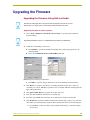
Upgrading the Firmware Using NetLinx Studio ............................................................... 49
Upgrading Firmware on Axcess Systems .............................................................................. 49
Upgrading the Firmware Using SOFTROM .................................................................... 50
Configuration.......................................................................................................................... 50
Downloading the Firmware .................................................................................................... 50
ii
AXB-PT10/15/30 PosiTrack Camera Controllers
Introduction
Introduction
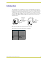
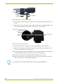
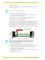
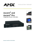
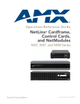
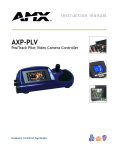
The AXB-PT10 PosiTrack 10, AXB-PT15 PosiTrack 15, and AXB-PT30 PosiTrack 30 Camera
Controllers (FIG. 1) are camera/lens controllers used for precise camera-positioning applications.
Each PosiTrack unit supports both AXlink and RS-232 control protocols and connects directly to
an AXlink network. All controllers contain on-board intelligence for consistent motion and lens
control. The AXB-PT10 and AXB-PT15 Camera Controllers use identical connectors and camera
mounts but support different camera/lens weights (refer to the Specifications section for more
detailed information).
Dual Camera/
Lens Cradle
Assembly
(PT15 uses the
same camera mount
as the PT10)
PosiTrack 10
RS-232
LENS
PosiTrack 30
Single
Camera/Lens
Cradle
RS-232
LENS POWER
PANJA
CAM
LENS
AXlink
LENS POWER
AMX
TM
CAM
AXlink
FIG. 1 AXB-PT10 and AXB-PT30 PosiTrack Camera Controllers (side views)
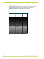
The following table shows the PosiTrack unit lens compatibility.
PosiTrack Unit Lens Compatibility
Fujinon Lenses
Canon Lenses
MD
KTSA
BMD
RGE PZF
AMSR
R
MPX
REA
SNPY
REA-IA
MDM
REA-IA PZF
SNDS
RGE
AXB-PT10/15/30 PosiTrack Camera Controllers
1
Introduction
Specifications
The following table lists the specifications for all PosiTrack units.
Specifications
Dimensions (HWD):
AXB-PT10
Camera controller: 5.85" x 5.20" x 4.92" (14.86 cm x 13.22 cm x 14.70 cm)
Camera mount: 0.65" x 2.26" x 3.23" (1.75 cm x 5.74 cm x 8.21 cm)
Cradle support bracket: 3.64" x 5.50" x 0.20"
(9.25 cm x 13.97 cm x 0.51 cm)
Dimensions (HWD):
AXB-PT15
Camera controller: 6.43" x 5.61" x 5.38"
(16.32 cm x 14.25 cm x 13.67 cm)
Camera mount: 0.65" x 2.26" x 3.23" (1.75 cm x 5.74 cm x 8.21 cm)
Cradle support bracket: 3.64" x 5.50" x 0.20"
(9.25 cm x 13.97 cm x 0.51 cm)
Dimensions (HWD)
AXB-PT30
Camera Controller: 7.10" x 5.70" x 4.65" (18.03 cm x 14.49 cm x 11.81 cm)
Camera Cradle: 4.75" x 3.75" x 6.25" (120.67 mm x 95.28 mm x 158.75 mm)
Power Consumption:
AXB-PT10
2.6 A max @ 12 VDC
AXB-PT15
4 A max @ 12 VDC
AXB-PT30
6 A max @ 12 VDC
Weight:
AXB-PT10
8.00 lbs. (3.63 kg)
AXB-PT15
10.51 lbs. (4.77 kg)
AXB-PT30
13.05 lbs. (5.92 kg)
Angular Travel:
Pan
± 179° (358° total)
Tilt
± 90° (180° total)
Maximum Speed:
AXB-PT10
AXB-PT15
AXB-PT30
• Pan
45°/sec.
• Tilt
45°/sec.
• Pan
55°/sec.
• Tilt
55°/sec.
• Pan
35°/sec.
• Tilt
35°/sec.
Weight Capacity:
AXB-PT10
10 lbs. (4.54 kg) balanced lens/camera weight (maximum)
AXB-PT15
15 lbs. (6.80 kg) balanced lens/camera weight (maximum)
AXB-PT30
30 lbs. (13.6 kg) balanced lens/camera weight (maximum)
Repeatability:
2
AXB-PT10
± 5 arc minutes
AXB-PT15
± 3 arc minutes
AXB-PT30
± 5 arc minutes
AXB-PT10/15/30 PosiTrack Camera Controllers
Introduction
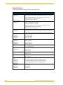
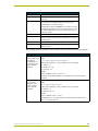
Specifications (Cont.)
DIP Switches:
• (S2) - RS-232 communication (baud rate)
• (S5) - AXlink communication (device #)
Presets:
Stores up to 255 presets for pan, tilt, zoom, focus, and iris operations; 127 of
those presets return a status when queried.
Relays:
Solid-state relays for servomotor lens mode control (zoom/focus speed/position
and iris local/auto)
Optical Centerline:
Optical centerline is between 1/2" and 5" above the mounting plane of the camera/lens (this allows the mounting of the camera/lens so that the tilt axis is
capable of going through the optical axis of the camera)
Environmental Parameters:
32° F to 120° F (0° C to 48.8° C) ambient temperature range
Enclosure:
Metal with enamel and anodized matte finish
Control Panel:
• RS-232 DB-9 connector (300 baud - 38.4 KB communication for camera
control)
• DB-15 high density connector (lens control)
• Lens power switch (powers or isolates the camera lens)
• AXlink 4-pin connector (provides AXlink, RS-232 stand-alone
communication, and power connection points)
Battery:
Lithium battery to protect preset memory (up to 10 years)
Connectors:
• 4-pin captive wire (AXlink)
• DB-15 HD 15-pin high-density (female) for lens control
• DB-9 9-pin D-sub (male) for RS-232 camera control
Optional Accessories:
• CC-CAM lens control cable (specify make and model)
• CC-CAM RS-232 camera control cable (specify make and model)
• Pedestal mount (PM-CAM, PosiTrack Pedestal Mount)
• PSN2.8 Power Supply (for use with the PT10 Camera Controller)
• PSN6.5 Power Supply (for use with the PT10/15/30 Camera Controllers)
- This power supply can be used with ALL PosiTrack units
• Tripod mount (TM-CAM, PosiTrack Tripod Mount Adapter)
• Wall-mount bracket (WM-CAM, PosiTrack Wall Mount)
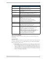
Lens Control Modes
The Servomotor and Motor modes are two Analog Voltage Control methods available on the
PosiTrack units.
Servomotor Mode
This method is generally used in broadcast or videoconference-style lenses. The voltage range used
for servomotor style lenses is +2.5 to +7.5 VDC. These lenses can be controlled in two different
modes: positional mode and speed mode.
Positional mode is the most common Servomotor mode. When voltage changes, the lens
moves and remains still until the voltage changes again. For example, if a lens receives a
voltage of +3 VDC, the lens moves to the corresponding position and stays there as long
as the voltage remains at +3 VDC. The movement speed of the lens motor is a function of
the PosiTrack unit’s analog output. The lens servomotor receives the preset voltage when
a preset is recalled in the positional mode.
AXB-PT10/15/30 PosiTrack Camera Controllers
3
Introduction
Speed mode moves the lens when the voltage deviates from the center point of its range.
The farther the voltage moves away from the center point of reference, the faster the lens
motor moves. The lens must have POT outputs when recalling a preset in this mode,. The
outputs pass to the PosiTrack unit, and when the received voltage level matches the level
stored in the preset, the voltage returns to zero. Servomotor speed mode lenses not
having POT outputs do not have preset recall capability.
Motor Mode
Motor mode is used when the lens requires the motors be directly driven from an external source.
The standard voltage ranges are ± 6 VDC or ± 12 VDC with a center (no motion) of 0 VDC. Unlike
servomotor lenses, these only operate in speed mode.
The lens moves in relation to the voltage offset from zero. The farther the voltage moves away from
the center point, the faster the lens motor moves. The lens must have POT outputs when recalling a
preset in this mode, these outputs are then passed to the PosiTrack unit. When the received voltage
level matches the level stored in the preset, the voltage returns to zero. Motor mode lenses not
having POT outputs do not have preset recall capability.
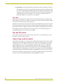
Pan and Tilt Control
Presets and travel limit stops are based on encoder counts from a home position index, located at
the center of each axis’ range of motion.
Zoom, Focus, and Iris Control
Each PosiTrack unit delivers a low voltage pulse-width-modulated output for zoom, focus, and iris
functions for motor mode lenses. These units are also capable of receiving reference voltage rails
and sending zoom, focus, and iris control signals in response to these rails. In this setting (slideswitch configured), no active control signals will reach the lens before power (+ 12 VDC and
GND) is supplied to the lens. This motor mode applies to the control of the Fujinon and Canon
teleconferencing lenses. During preset recall operation, these outputs are synchronized with the pan
and tilt motions. Refer to the PosiTrack Unit Lens Compatibility table on page 1. Four solid state
relays are also provided to control the zoom, focus, and iris speed/position mode selection and iris
local/auto selection on the Fujinon MD series and Canon KTSA series lenses.
4
AXB-PT10/15/30 PosiTrack Camera Controllers
Introduction
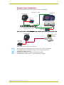
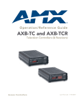
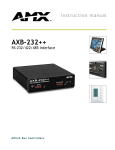
Sample Product Application
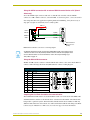
FIG. 2 shows a sample camera control application using the AXB-PT10.
Application #1 - AXlink
AMX AXP-PLV
AMX AXB-PT10
AMX Local
Power Supply
PWR cable
RS-232 / 422
AXP
GND
AXM
AXlink
PWR
GND
485EN
TX1
RX1
RX
RX
TX
TX
V
CTS2
GND
RTS2
RS-232
RX2
AXlink
TX2
AMX AXB-EM232 (rear view)
12VDC
PWR
AXlink
AMX ABS (AXlink Bus Strip)
AMX PS2.8
Power Supply
PWR cable
Application #2 - RS-232
AMX AXB-PT10
PC or other
RS-232
controller
AMX Local
Power Supply
PWR cable
FIG. 2 Sample AXB-PT10 camera product application
Use a separate power supply to power each PosiTrack unit. Power to the PosiTrack
unit is supplied from the external power supply to the unused power pin on the
PosiTrack unit’s AXlink connector.
The AXB-PT10 unit requires a PSN2.8 or PSN6.5 power supply.
The AXB-PT15 and AXB-PT30 units require a PSN6.5 power supply.
AXB-PT10/15/30 PosiTrack Camera Controllers
5
Introduction
6
AXB-PT10/15/30 PosiTrack Camera Controllers
Pre-Installation
Pre-Installation
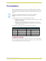
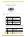
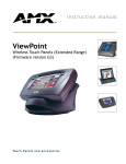
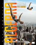
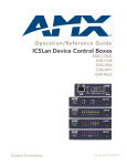
There are four SPDT slide switches in the lens control section (FIG. 3). Three of the switches
toggle the lens control selection between servomotor or motor mode hardware for control of zoom,
focus, and iris. The fourth selects between ± 6 VDC and ± 12 VDC control for motor mode lens
functions.
An SPDT switch is a Single Pole-Double Throw switch. This switch is completed at
both positions. An example is the Volt switch that is active in both the 6 and 12
positions.
Each PosiTrack unit consists of two main Printed Circuit Boards (PCBs):
PosiTrack Processor PCB (PosiTrack Mother Board) contains the main processor, 2MB
FlashROM, and 2MB SRAM.
PosiTrack Power Management PCB (PosiTrack Daughter Board) contains power
conditioning circuitry, control outputs/inputs to the pan/tilt drives, and zoom/focus/iris
outputs, and inputs to the lenses.
The following table shows the necessary tools when working on the PosiTracks.
Necessary Tools
AXB-PT10/15
AXB-PT30
3/32 HEX KEY
Anti-Rotation Pin
5/64 HEX KEY
Cover Screws
3/16 HEX KEY
Camera Mount Screw
1/16 HEX KEY
Bezel and Connector Screws
1/16 HEX KEY
Cover Screws and Connector
Bezel
3/32 HEX KEY
Camera Mount ADJ. Screws
5/64 HEX KEY
Tilt Arm Screws
5/64 HEX KEY
Tilt Arm Screws
3/32 HEX KEY
Camera Mount ADJ. Screws
3/32 HEX KEY
Camera Mount ADJ. Screws
Configuration Settings
Both PosiTrack units contain switches for setting the control mode, lens control voltage, RS-232
baud rate, and AXlink address. Before installing the PosiTrack unit, you must set the DIP switches,
lens control mode switches, and lens control voltage switch.
AXB-PT10/15/30 PosiTrack Camera Controllers
7
Pre-Installation
AXlink
LED
S6 VOLT
6
12
S
M
S
M
S
M
RS-232
S1 ZOOM
S3 FOCUS
S4 IRIS
AXlink
FIG. 3 Lens control section (back panel)
Setting zoom, focus, and iris switches to servomotor or motor mode
Both PosiTrack units support servomotor (+2.5 to +7.5 VDC operating range) and direct-drive
motor (± 6 VDC or ± 12 VDC operating range) lens control. The table below shows how to set the
switches for servomotor mode (S) or motor mode (M). If you are using a direct-drive lens, refer to
the manufacturer's literature to set the VOLT switch for ± 6 or ± 12 VDC control.
Servomotor and Motor Voltage Switch Settings
Servomotor mode
Motor mode (+ 6 VDC) Motor mode (+ 12 VDC)
VOLT
VOLT
6
VOLT
12
ZOOM
6
12
ZOOM
S
M
FOCUS
S
M
FOCUS
S
M
IRIS
S
M
12
S
M
S
M
S
M
FOCUS
M
IRIS
S
6
ZOOM
IRIS
S
M
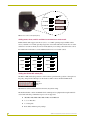
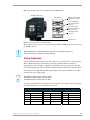
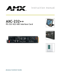
Setting the RS-232 DIP switch (S2)
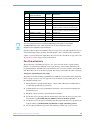
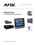
The RS-232 DIP switch (S2) positions 1 and 2 set the stop and data bits, positions 3 through 5 set
the parity, and positions 6 through 8 set the baud rate. FIG. 4 shows the RS-232 DIP switch.
RS-232
DIP switch
(S2)
1 2 3 4 5 6 7 8
FIG. 4 RS-232 communications parameters DIP switch (S2) (default setting)
The PosiTrack units contain one EIA RS-232C standard port for equipment that requires RS-232
control. The following communication protocols are supported:
300, 600, 1200, 2400, 4800, 9600, 19200, and 38400 baud
7, 8, or 9 Data bits
1 or 2 Stop bits
Even, Odd, and None parity settings
8
AXB-PT10/15/30 PosiTrack Camera Controllers
Pre-Installation
The RS-232 factory default communications settings are: 9600 baud, No Parity, 8 bits, and 1 stop
bit. The following table lists the RS-232 Port DB-9 (male) pinouts.
RS-232 Port DB-9 (male) Pinouts
Pin
Signal
Function
1
N/A
N/A
2
RXD
RXD
3
TXD
TXD
4
N/A
N/A
5
GND
GND
6
N/A
N/A
7
RTS
RTS
8
CTS
CTS
9
N/A
N/A
The following table lists the RS-232 DIP switch settings.
RS-232 DIP Switch (S2) Settings
Position
1
2
Function
Stop Bits
Data Bits
3
Off
Off
2 bits
7 bits
On
1 bit
8 bits
5
6
Parity
Off
On
4
Off
Off
Off
Off
On
Off
On
On
Off
Off
Off
Off
On
Off
On
Off
On
On
On
On
None
Off
On
Off
Off
On
Off
On
9,600
On
Off
Odd
On
On
4,800
Even
Off
Off
2,400
Unused
On
Off
1,200
Unused
Off
Off
600
Unused
On
Off
300
Unused
Off
8
Baud Rates
Unused
On
7
On
On
19,200
On
On
On
On
38,400
Setting the AXlink Device DIP switch (S5)
The eight-position Device DIP switch (S5), shown in FIG. 5, must match the number assigned in
the Axcess software program. The Device DIP switch example is set to 90 (2 + 8 + 16 + 64 = 90),
the factory default setting.
AXlink
DIP switch
(S5)
1 2 3 4 5 6 7 8
FIG. 5 AXlink device DIP switch (S5) (default value of 90)
AXB-PT10/15/30 PosiTrack Camera Controllers
9
Pre-Installation
The AXlink device number range is 1-255. The Device DIP switch positions determines their
values, based on the following table:
Device DIP Switch (S5) Settings and Values
Position
1
2
3
4
5
6
7
8
Value
1
2
4
8
16
32
64
128
After setting the AXlink device number, remove and reconnect the AXlink connector on the
PosiTrack unit to save the new number.
Accessing the AXB-PT10 and AXB-PT15 Internal Jumpers
Jumpers J6 through J8, located on the circuit board inside the PT10 and PT15, set the
communication mode to AXlink (factory default) or RS-232.
You need a 5/64" (1.98 mm) and 1/16" (1.59 mm) Allen wrench to open the unit, and a pair of nonconducting pliers to set the jumpers using the following steps.
Remove the control panel before you remove the cover, in order to avoid any damage
to the unit.
1. Discharge any accumulated static electricity from your body before removing the enclosure.
Remove the static electricity by touching a grounded metal object.
2. Unplug all connectors from the rear panel of the PosiTrack unit.
3. Remove the four screws, located around the connector panel (FIG. 6), by using the 1/16" Allen
wrench. BHSC is the abbreviation for the Button Head Socket Cap screws.
BHSC screws
(two screws
in rear)
BHSC screws
(two screws on top)
Tilt-head screws (four
screws available)
RS-232
BHSC screws
(five screws on each side)
LENS
LENS POWER
AMX
CAM
AXlink
Connector panel
(four screws)
FIG. 6 Pan-head screw locations
4. Carefully pull the connector panel away from the main unit until the bottom edge of the cover
clears the connector panel. Be careful not to damage the pins attached to the connector panel.
FIG. 7 illustrates how to remove the control panel.
5. Using the 1/16" Allen wrench, remove the 14 BHSC screws, from the left, right, top, and back
sides of the PosiTrack unit.
10
AXB-PT10/15/30 PosiTrack Camera Controllers
Pre-Installation
Pins that connect
the control panel
to the motherboard
FIG. 7 Control panel removal for PT10 and PT15
6. Carefully pull the cover straight up from the main unit, until the bottom edge of the cover
clears the connector panel and then slide it backwards (as seen in FIG. 8).
FIG. 8 Removing cover on the PT10 and PT15
Accessing the AXB-PT30 Internal Jumpers
Jumpers J6 - J8, located on the circuit board inside the AXB-PT30, set the communication mode to
AXlink (factory default) or RS-232.
You need a 5/64" (1.98 mm) and 1/16" (1.59 mm) Allen wrench to open the unit, and a pair of nonconducting pliers to set the jumpers using the following steps.
1. Discharge any accumulated static electricity from your body before removing the enclosure.
Remove the static electricity by touching a grounded metal object.
2. Unplug all connectors from the rear panel of the AXB-PT30.
3. Using the 1/16" Allen wrench, remove the four #4-40 socket head screws located around the
connector panel (FIG. 9), by using.
4. Remove the 16 BHSC screws, using the 5/64" Allen wrench, from the left, right, top, and back
sides of the AXB-PT30. A sample view of the screw locations is shown in FIG. 9.
5. Carefully pull the cover straight up from the main unit, until the bottom edge of the cover
clears the connector panel, and place the cover aside (see FIG. 8).
AXB-PT10/15/30 PosiTrack Camera Controllers
11
Pre-Installation
BHSC screws
(two screws on top)
Connector panel
(four screws)
BHSC screws
(six screws on
each side)
PosiTrack 30
BHSC screws
(two on the rear)
RS-232
LENS
LENS POWER
AMX
CAM
AXlink
FIG. 9 Pan-head screw locations
Setting the Internal Jumper Communication Mode
1. Locate jumpers J6, J7, and J8 communication mode jumpers on the Mother PCB (FIG. 10).
The connectors and the main board are mounted onto the pan base.
2. Set the jumpers for either AXlink or RS-232 communication.
Jumper
locations
(3 pair)
J8
J6
J6, J7, and J8
communication
mode settings
Lens control
section
FIG. 10 Communication mode jumpers J6, J7, and J8 (factory default set to AXlink)
3. Set the jumpers for either AXlink or RS-232 communication.
Jumper Settings (top view)
AXlink (pins 1 & 2)
RS-232 (pins 2 & 3)
AXlink
Jumper 7
Jumper 6
Pin #s 1 2 3
12
RS-232
AXlink
RS-232
Jumper 8
Jumper 8
MOTOR
Jumper 7
MOTOR
Jumper 6
Pin #s 1 2 3
AXB-PT10/15/30 PosiTrack Camera Controllers
Pre-Installation
For RS232 stand-alone mode, the 8-position AXlink Device DIP switch must be set to
all off (down position).
4. Carefully place the cover back onto the main unit by sliding it over the internal gears and
motherboard.
5. Align the Control panel screw holes. Make sure the cables are not pinched in the back panel or
drive gears.
6. Insert the 14 BHSC screws and tighten securely using the 1/16" Allen wrench.
Steps 6 and 7 apply to the AXB-PT10/PT15 units where the removal of the Control
Panel differs from the PT30.
7. Carefully insert the connector panel, on the PT10/15, into the opening on the side of the unit
and connect it to the motherboard located inside the unit.
8. Firmly secure the control panel to the motherboard.
9. Using the 1/16" Allen wrench, insert the four BHSC screws, located around the connector
panel.
10. Use the wire tie-mount to secure connector cables.
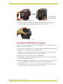
Configuring An External Camera/Lens Power Supply
The camera/lens power switch, located between the AXlink and DB-15 connectors, regulates the
power to the camera/lens from the PosiTrack unit. The power switch, seen in FIG. 6 and FIG. 9,
Opens (turns Off) or Closes (turns On) the circuit feeding power to the camera/lens assembly. Refer
to the Wiring the Connectors section on page 20 for more information about the control panel.
Flip the Lens Power switch to the left if you are only providing power to the camera/lens
assembly through the PosiTrack unit.
Flip the Lens Power switch to the right if you are providing external power to the camera/
lens assembly. By turning the switch Off, the dedicated +12 VDC stops providing
additional power to the camera/lens; preventing damage to power supplies and noise in
the video cables.
AXB-PT10/15/30 PosiTrack Camera Controllers
13
Pre-Installation
14
AXB-PT10/15/30 PosiTrack Camera Controllers
Installation
Installation
IMPORTANT! READ THIS DOCUMENT BEFORE MOUNTING CAMERA.
Proper balance of the camera mount (with camera/lens/cradle) will result in optimal
performance. Follow these balancing instructions prior to operation. Failure to
balance the camera mount can result in poor performance.
The PosiTrack units enable pan and tilt functionality for mounted camera/lens assemblies and
provides lens control functions for teleconferencing lenses. Digital encoders are installed on both
the pan and tilt drives, allowing positional feedback for presets, and to provide accurate speed
control. Software adjustable stop limits are used on the pan and tilt drives to limit the range of
motion.
Do not mount a PosiTrack unit in any location where the motion of the camera/lens is
obstructed by any object.
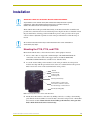
Mounting the PT10, PT15, and PT30
Mount the PosiTrack units to a flat horizontal surface, either upright or inverted.
1. Select a surface that can support the combined weight of the PT10/ PT15/PT30, the
camera/lens, and control cables. Some support surfaces include the WM-CAM,
PM-CAM, and TM-CAM mounts available for use with these units.
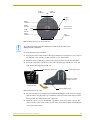
2. Locate the external white position markers located on the pan and tilt axis. The position
markers must align with the pan and tilt axis in order to be considered in the home position.
FIG. 11 shows the camera cradle attachment in the center position.
Tilt Hub
Central tilt-axis
Camera cradle
mounting holes
Camera points this way
Position markers, located on the
outer surfaces, mark the center for
the vertical range of camera motion
Pan hub (mounting plate)
FIG. 11 Center position for the camera cradle attachment
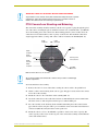
3. Mount the PosiTrack unit to a flat surface by drilling four holes, according to the mountingplate dimensions shown in FIG. 12. Secure the unit to the surface using four 1/4" x 20 machine
bolts and lock washers. Ensure that the external white position marker, on the pan drive
hub, is inside the desired camera rotation range.
AXB-PT10/15/30 PosiTrack Camera Controllers
15
Installation
Position marker
(on the outer surface)
Camera points this way when the pan drive is in
the center of its range of motion (Home position)
Ø 3.453"
87.7 mm
3.00 BHC"
76.20 mm
3.45"
(87.7mm)
FIG. 12 Tilt Hub (Mounting plate) dimensions
Each PosiTrack unit can be mounted to camera mounts such as the TM-CAM, WM-CAM, and
PM-CAM as shown in FIG. 13.
Cradle support bracket
Camera mount assembly
PM-CAM (Pedestal mount)
Wire
tie-mount
FIG. 13 Pedestal mount
The camera/lens cradle can be mounted on either side of the cradle support bracket.
PT10 and PT15 Camera/Lens Mounting and Balancing
The camera/lens assembly should be mounted so the tilt axis is capable of going through the optical
axis of the camera, assuming the optical centerline is between 1/2" (12.70 mm) and 5" (127.00 mm)
above the mounting plane of the camera lens. The mounting platform (camera cradle) allows the
camera/lens to be mounted with its center of gravity on the tilt axis. The maximum weight of the
camera/lens assemblies on the PT10 is 10 lbs. (4.54 kg) and on the PT15 is 15 lbs. (6.80 kg). The
camera cradle is mounted to the Tilt Hub (FIG. 14).
16
AXB-PT10/15/30 PosiTrack Camera Controllers
Installation
0.750"
19.05 mm
0.750"
0.00" 19.05 mm
Position
markers
0.750"
19.05 mm
0.250"
6.35 mm
Camera points
in this direction
0.00"
0.250"
6.35 mm
0.750"
19.05 mm
0.56"
39.62 mm
FIG. 14 Tilt Hub dimensions for the PT10/15 units
Do not lift the PosiTrack unit by the Camera/Lens cradle as this procedure could
damage internal components.
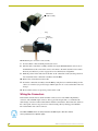
To mount and balance the camera/lens:
1. Separate the camera mount and the cradle support bracket by removing the two 1/2" screws on
the underside of the assembly (see FIG. 15) using a 3/32" Allen wrench.
2. Install the camera alignment peg to the mount at the position that best fits the camera/lens.
3. Secure the camera/lens to the mount (at the camera alignment peg) with the 1/2" screw and
1/10" thick washer supplied (see FIG. 15).
Mounting holes (three sets)
Cradle support bracke
Camera/Lens cradle
assembly (side view)
Camera mount
(underside view)
Camera alignment peg
FIG. 15 Camera bracket assembly
4. Place the assembly on a balancing beam and while maintaining the cradle centered on the pipe,
slide the camera along the cradle’s groves until the camera and cradle remain balanced on the
beam (see FIG. 16). Verify balance with a spirit level.
5. Mount the camera as close to the Tilt Hub as possible to obtain a true center of gravity. The
center of gravity is the location on the long axis of the camera/lens assembly around which the
camera and mount balances.
AXB-PT10/15/30 PosiTrack Camera Controllers
17
Installation
cradle
(bottom view)
balancing beam
FIG. 16 Balancing the camera/lens cradle assembly
6. Re-attach the camera mount (with camera/lens) to the cradle support bracket using the two 1/2"
screws.
7. Take the entire camera/mount and cradle assembly and align the lens with the Tilt Hub so that
the vertical-axis intersects the center of the camera’s iris, as shown in FIG. 17.
Marker points
Iris
Vertical tilt-axis
FIG. 17 Iris alignment with vertical tilt-axis
8. Mark the position of the cradle support bracket on the Tilt Hub (for later attachment).
9. Remove the camera/lens and mount piece from the support bracket by unscrewing the two 1/2"
screws on the underside of the camera mount.
10. Secure the support bracket to the Tilt Hub (at the same position marked for the iris alignment)
on the PosiTrack unit with some or all of the four 1/2" screws and washers.
11. Secure the camera/mount to the support bracket by using the two 1/2" screws.
12. Support the weight of the camera cables with a wire tie attached to the wire tie mount on the
lower corner of the face of the PosiTrack unit (FIG. 13).
The camera/lens cradle can be mounted on either side of the cradle support bracket.
18
AXB-PT10/15/30 PosiTrack Camera Controllers
Installation
IMPORTANT! READ THIS DOCUMENT BEFORE MOUNTING CAMERA.
Proper balance of the camera mount (with camera/lens/cradle) will result in optimal
performance. Follow these balancing instructions prior to operation. Failure to
balance the camera mount can result in poor performance.
PT30 Camera/Lens Mounting and Balancing
The camera/lens assembly should be mounted so the tilt axis is capable of going through the optical
axis of the camera, assuming the optical centerline is between 1/2" (12.70 mm) and 5" (127.00 mm)
above the mounting plane of the camera lens. The mounting platform (camera cradle) allows the
camera/lens to be mounted with its center of gravity on the tilt axis. The maximum camera/lens
weight supported is 30 lbs. (13.6 kg). The camera cradle is mounted to the Tilt Hub (FIG. 18).
0.984"
24.99 mm
0.984"
0.00" 24.99 mm
Position
markers
0.984"
24.99 mm
0.328"
8.33 mm
0.00"
Camera points
in this direction
0.328"
8.33 mm
0.984"
24.99 mm
Ø 3.500"
88.97 mm
FIG. 18 Tilt Hub dimensions for the PT30
Do not lift the PT30 by the Camera/lens cradle as this procedure could damage
internal components.
To mount and balance the assembly:
1. Remove the four 1/2" screws and washers securing the camera cradle to the pan/tilt head.
2. Obtain a camera and a balancing beam, such as a pipe. The pipe is used to balance the camera/
lens on the cradle assembly.
3. Mount the camera to the camera/lens cradle assembly (FIG. 19).
4. Attach the camera/lens to the cradle with a fastener recommended by the camera manufacturer.
Allow the camera to slide along the horizontal grooves without sliding off.
5. Place the assembly on the balancing beam and while maintaining the cradle centered on the
pipe, slide the camera along the cradle’s grooves until the camera and cradle remain balanced
on the beam (FIG. 20). Verify the balance with a spirit level.
6. Mount the camera as close to the Tilt Hub as possible to obtain a true center of gravity. The
center of gravity is the location on the long axis of the camera/lens assembly around which the
camera and mount balances.
AXB-PT10/15/30 PosiTrack Camera Controllers
19
Installation
Camera/lens
cradle assembly
FIG. 19 Camera/lens cradle assembly mounting
Tilt-axis
mount slots
FIG. 20 Balancing the camera/lens cradle assembly
7. Secure both the camera mounting and tilt-axis screws.
8. Take the entire camera/lens assembly and slide it along the Tilt Hub until the vertical-axis of
the PT30 intersects the center of the camera’s iris. Refer to the PT10 and PT15 Camera/Lens
Mounting and Balancing section on page 16 for more information on alignment.
9. Mark the position of the white tilt-axis marker on the camera/lens cradle (use this position for
later attachment of the camera/lens assembly to the Tilt Hub).
10. Remove the camera/lens from the cradle.
11. Secure the camera/lens assembly to the Tilt Hub by using the lens centerline markings for the
camera as a reference (see previous step) with the eight 32x 3/4" screws and washers removed
in step 1.
12. Re-attach the camera to its previous position on the cradle.
Wiring the Connectors
Each PosiTrack Controller has an RS-232 DB-9 connector, lens control DB-15 high-density
connector, and an AXlink 4-pin connector. Always provide enough cable to accommodate the
desired range of motion for the PosiTrack units and their camera/lenses. The Lens Power switch on
the control panel, removes any power noise on the incoming video by turning power On/Off to
Pin 1 of the DB-15 lens control connector.
The LENS POWER switch can turn power Off to the DB-15 pin 1 when the camera/
lens is powered from a separate supply.
20
AXB-PT10/15/30 PosiTrack Camera Controllers
Installation
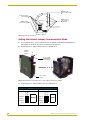
FIG. 21 shows the location of each connector on the AXB-PT10/15.
AXB-PT10 (side view)
Camera control RS-232
DB-9 (male) connector
Control panel
Lens control DB-15
high density (female)
connector
Lens Power switch
Pin 1 power switch for
DB-15 connector
LENS POWER
AMX
AXlink 4-pin (male)
connector
CAM
Wire tie-mount
FIG. 21 Control panel location on the AXB-PT10/15
The PosiTrack Controller receives all power from the +12 VDC and GND connections on the fourpin AXlink connector.
When applying power to the AXB-PT10/15, adjust the soft-set pan/tilt limit stops to a
safe position to prevent camera or PosiTrack damage.
Wiring Guidelines
In most installations, the PosiTrack Controllers require local +12 VDC power to operate properly.
The maximum wiring distance between the power supply and the PosiTrack Controller is
determined by power consumption, supplied voltage, and the wire gauge used for the cable. The
following wiring table lists wire sizes and the maximum lengths allowable between the PosiTrack
units and the power supply. The maximum wiring lengths are based on a minimum of 13.5 VDC,
available at the power supply output.
The AXB-PT10 power rating is 2.6 A @ 12 VDC.
The AXB-PT15 power rating is 4 A @ 12 VDC.
The AXB-PT30 power rating is 6 A @ 12 VDC.
To reduce the possible effects of ground loop noise in the video, use a single-source power supply
mounted within distances specified in the following table.
Wiring Guidelines - PT10, PT15, PT30 (Based on a +12VDC Power Supply)
Wiring Guidelines - PT10 (2.6 A)
Wiring Guidelines - PT15 (4 A)
Wiring Guidelines - PT30 (6 A)
Wire size
Max. wiring length
Wire size Max. wiring length
Wire size Max. wiring length
18 AWG
45.14 ft (13.76 m)
18 AWG
29.34 ft (8.94 m)
18 AWG
19.56 ft (5.96 m)
20 AWG
28.56 ft (8.71 m)
20 AWG
18.56 ft (5.66 m)
20 AWG
12.38 ft (3.77 m)
22 AWG
17.80 ft (5.43 m)
22 AWG
11.57 ft (3.53 m)
22 AWG
7.72 ft (2.35 m)
24 AWG
11.22 ft (3.42 m)
24 AWG
7.30 ft (2.22 m)
24 AWG
4.86 ft (1.48 m)
AXB-PT10/15/30 PosiTrack Camera Controllers
21
Installation
Preparing captive wires
You will need a wire stripper and flat-blade screwdriver (approximately 1/8") to prepare and
connect the captive wires.
Never pre-tin wires for compression-type connections.
1. Strip 0.25 inch (6.35 mm) of insulation off all wires.
2. Insert each wire into the appropriate opening on the connector, according to the wiring
diagrams and connector types described in this section.
3. Turn the screws clockwise to secure the wire in the connector. Do not tighten the screws
excessively; doing so may strip the threads and damage the connector.
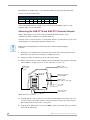
Using the AXlink connector for data and power
To use the AXlink 4-pin connector for data communication with the Central Controller and power
transfer from the local power supply (PSN), the incoming PWR and GND cable from the local
power supply must be connected to the AXlink cable connector going to the PosiTrack Controller.
FIG. 22 shows how the power cable from the local power supply is used to power the PosiTrack
Controller and the GND cable is connected onto the existing GND cable on the AXlink cable
coming from the Central Controller. Always use a local power supply to power the PosiTrack unit.
PWR (+)
Local +12 VDC power supply
(coming from the PSN power supply)
GND (-)
PWR +
PWR +
AXP/TX
AXP/TX
AXM/RX
AXM/RX
GND -
GND -
To the Central Controller
To the PosiTrack unit
FIG. 22 AXlink connector and local +12 VDC power supply wiring diagram
Do not connect the wire from the PWR terminal on the Central Controller to the PWR
terminal on the PosiTrack unit when you connect an external power supply. Make
sure to connect only the AXM, AXP, and GND wires on the PosiTrack unit’s Axlink
connector when using a local power supply.
1. Unscrew the PWR and GND wires on the terminal end of the PSN’s 2-pin cable.
2. Pair the GND wires from the PSN and the Central Controller AXlink connectors together and
insert them into the clamp position for GND on the PosiTrack unit’s AXlink connector.
3. Tighten the clamp to secure the two GND wires.
4. Place the PWR wire from the PSN into the open clamp position for PWR on the PosiTrack
unit’s AXlink connector.
5. Tighten the clamp to secure the PWR wire.
22
AXB-PT10/15/30 PosiTrack Camera Controllers
Installation
Using the AXlink connector with an external RS-232 control device or PC (StandAlone only)
To use the AXlink 4-pin connector with a PC or other RS-232 controller, wire the AXlink
connector to a DB-9 female connector, as shown in FIG. 23. Connector pins 2, 3, and 5 are used for
data and ground. For some applications requiring hardware handshaking, it may be necessary to
strap pins 7 (request to send) and 8 (clear to send) together.
PWR (+)
GND (-)
PWR +
2 (RXD)
AXP/TX
AXM/RX
3 (TXD)
GND -
5 (GND)
PosiTrack unit
AXlink connector
External RS-232
DB-9 connector
(female)
FIG. 23 External RS-232 control device or PC wiring diagram
For RS232 stand-alone mode, the 8-position AXlink Device DIP switch (S5) positions
1 thru 8 must all be set to Off (all down) and the internal communication jumpers must
be set to RS232 mode. For more information, refer to the Jumper Settings (top
view) table on page 12.
Using the RS-232 DB-9 connector
The RS-232 DB-9 (male) connector on the PosiTrack units connect to the camera head’s RS-232
connector. The following table shows the (DB-9) RS-232 connector wiring diagram.
(DB-9) RS-232 Connector Pinouts
Pin
Signal
Function
1
N/A
Not used
2
RXD
Receive data
3
TXD
Transmit data
4
DTR
Data terminal ready (not used)
5
GND
Signal ground
6
DSR
Data set ready (not used)
7
RTS
Request to send (not used)
8
CTS
Clear to send (not used)
9
N/A
Not used
9
8
9
8
5
4
3
2
1
7
6
Female
7
6
Male
Preparing the PosiTrack Controllers for communication
The AXlink Device DIP switch is located beneath the round cover on the back of the PT10, PT15
and PT30. Set these switches to the desired device value based on the number of PosiTrack units
being used in a particular system. The initial unit is defaulted with a device number of #90. Any
additional units must have values that do not conflict with other PosiTrack units being used. Refer
to the Setting the AXlink Device DIP switch (S5) section on page 9 for more information.
AXB-PT10/15/30 PosiTrack Camera Controllers
23
Installation
Using the lens control DB-15 HD (high density) connector
The PosiTrack Controllers are designed to control servomotor and motor mode camera lenses. See
the Pre-Installation section on page 7 to set the lens switches for servomotor or motor mode.
FIG. 24 shows the DB-15 HD connector pin numbers.
Pin 5
Pin 1
Pin 6
Pin 10
Lens control DB-15 HD
(female) connector
wiring pinouts
Pin 15
Pin 11
FIG. 24 Lens control DB-15 HD connector (female) wiring pinouts
DO NOT connect the motor-mode outputs to servo-mode lenses. This can result in
lens damage.
The following table lists the pinouts for motor mode lenses. Pin1 provides lens power from the
PosiTrack’s own power supply when the lens power switch is set to AMX (left).
Lens Control DB-15 HD Connector Pinouts for Motor Mode
Pin
PosiTrack DB-15 HD
connector functions
Direction
Lens function
1
+12 VDC
Output
Motor Power
2
GND
Output
Lens common
3
Zoom-drive
Output
Zoom motor
4
Focus-drive
Output
Focus motor
5
Iris-drive
Output
Iris motor
12
POT-REF+ (+5 VDC)
Output
POT-high side
13
POT-REF - (GND)
Output
POT-low side
14
Zoom-wiper
Input
Zoom-POT wiper
15
Focus-wiper
Input
Focus-POT wiper
Motor driven outputs are intended to drive conventional motors. These outputs can deliver up to
100 mA of current. The outputs use Pulse Width Modulation (PWM) for speed control. The output
voltage values are ± 6 VDC or ±12 VDC. Speed is controlled by varying the duty cycle of the
output.
Lens Control DB-15 HD Connector Pinouts for Servomotor Mode
PosiTrack DB-15 HD
connector functions
Pin
1
24
Direction
Lens function
+12 VDC
Output
Motor Power (see following note)
2
GND
Output
Lens common
3
Zoom-drive
Output
Zoom motor
4
Focus-drive
Output
Focus motor
5
Iris-drive
Output
Iris motor
AXB-PT10/15/30 PosiTrack Camera Controllers
Installation
Lens Control DB-15 HD Connector Pinouts for Servomotor Mode (Cont.)
PosiTrack DB-15 HD
connector functions
Pin
Direction
Lens function
6
Zoom-speed/position
Output
Zoom-positional/speed mode
7
Focus-speed/position
Output
Focus-positional/speed mode
8
Iris-local/auto
Output
Iris-local/auto select
9
Iris-speed/position
Output
Iris-positional/speed mode
10
VREF-A (+7.5V)
Input
VREF-A (+7.5 V). The reference voltage must be
present to operate correctly in servomotor mode.
11
VREF-B (+2.5 V)
Input
VREF-B (+2.5 V). The reference voltage must be
present to operate correctly in servomotor mode.
12
POT-REF+ (+5 VDC)
Output
POT-high side
13
POT-REF- (GND)
Output
POT-low side
14
Zoom-wiper (0-5 VDC)
Input
Zoom-POT wiper
15
Focus-wiper (0-5 VDC)
Input
Focus-POT wiper
Pin 1 is not required if the lens is powered independently. This feature is controlled by
the AMX/CAM switch on the connector panel. Pins 12-15 are required for Speed
mode but are not required for Positional mode.
Servomotor driven outputs are intended to drive servo-type motors only. The outputs have very low
current (milliampere range) capability. DO NOT attempt to drive conventional motors with these
outputs or you may damage the output drivers. If you are not sure about the motor type, refer to the
Specifications section on page 2 for more information.
Pan Characteristics
The pan drive has a maximum pan range of ± 179° (358° total). Pan travel is capable of being
limited to a restricted range around the center of pan travel by software limits adjustable by the
programmer/end user. Pan limits refer to the horizontal range of motion available to the PosiTrack
unit. These limits are set via the Axcess program. The center position marks the center of the range.
Setting the adjustable pan-limit stops
The Central Controller should be programmed by an AMX Axcess programmer before beginning.
Refer to the Specifications section on page 2 for more information on programming devices. To set
the adjustable pan-limit stops:
1. Ensure that there is enough slack in the lens, camera, and PosiTrack units’ AXlink cables to
accommodate the full range of pan motion.
2. Confirm that the necessary programming has been done to the system before beginning the
installation process.
3. Mount the camera controller to the desired horizontal surface.
4. Pan the unit as far to the left as desired and enter this position into the Axcess program as the
left pan-limit stop. The LEFT limit stop MUST be set left of the Home position.
5. Pan the unit as far to the right as desired and enter this position into the Axcess program as the
right pan-limit stop. The Right limit stop MUST be set right of the Home position.
6. Pan to both programmed stop positions and ensure the pan-limit stops are set correctly.
AXB-PT10/15/30 PosiTrack Camera Controllers
25
Installation
Tilt Characteristics
The tilt drive is factory set to a maximum tilt range of ± 90° (for a total of 180°). Tilt limit stops
refer to the vertical range of motion available to the PosiTrack unit and are set via the Axcess
program. The center position marks the center of the range.
Setting the adjustable tilt-limit stops
The Central Controller should be programmed before beginning. Refer to the Specifications section
on page 2 for more information on programming devices. To set the adjustable tilt-limit stops:
1. Ensure that there is enough slack in the lens, camera, and PosiTrack controller AXlink cables
to accommodate the full range of tilt motion.
2. Mount the PosiTrack Controller to the desired surface.
3. Tilt the unit as far up as desired and enter this position into the Axcess program as the upper
tilt-limit stop. The UP limit stop MUST be set above the Home position.
4. Tilt the unit as far down as desired and enter this position into the Axcess program as the lower
tilt-limit stop. The DOWN limit stop MUST be set below the Home position.
5. Tilt to both stop positions and ensure the tilt-limit stops are set correctly.
If you have problems setting the range of motion on either PosiTrack units, you may be setting both
limits on the same side of the Home position. You may need to set a new Home position before
proceeding.
See the Configuration Commands table on page 28 for details on the SET HOME command.
26
AXB-PT10/15/30 PosiTrack Camera Controllers
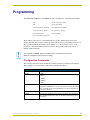
Programming
Programming
The AXB-PT10, AXB-PT15, and AXB-PT30 control capabilities for camera functions include:
• Pan
• Focus (servomotor; speed)
• Tilt
• Focus (motor drive)
• Zoom (servomotor; positional)
• Iris (servomotor; positional)
• Zoom (servomotor; speed)
• Iris (servomotor; speed)
• Zoom (motor drive)
• Iris (motor drive)
• Focus (servomotor; positional)
The PosiTrack Controllers are controlled with device-specific channel settings and Axcess
Send_Commands. You create the software programs with the Axcess programming software. Use
the programming information in this section, with the Axcess Programming Guide to create a
program to control the PosiTrack Camera Controllers. The program resides in the Axcess or
NetLinx Central Controller.
The commands for ZOOM, FOCUS, and IRIS output to servomotor or motor mode
MUST be configured to match the switch settings.
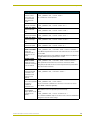
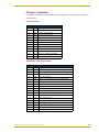
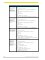
Configuration Commands
The following table lists in detail the different variables used in the Configuration Commands.
These variables consist of parameters which the commands must adhere to.
Variables for the Configuration Commands
Parameters
Description
Outputs
1—PAN
2—TILT
3—ZOOM
4—FOCUS
5—IRIS
Level
0 (lowest) to 255 (highest) or 0% to 100%
On pan, tilt, and PWM drives for zoom, focus, and iris, level 128 will be OFF.
Level 129 and above are for the forward direction. Level 127 and below are
for the reverse direction.
Time (optional)
If specified, 0 to 255 in tenths of a seconds; if not specified, at current rate.
Position
0 to 255; value of POT input. Corresponds to a position of the unit. 0 is one
end of the POT and 255 is the other end. Not directly related to an output
level voltage.
AXB-PT10/15/30 PosiTrack Camera Controllers
27
Programming
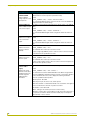
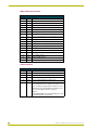
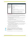
Variables for the Configuration Commands (Cont.)
Parameters
Description
Speed
0 to 127; where 0 is the slowest and 127 is the fastest (default).
Deviation
0 to 127; where 0 is most accurate but can have some jitter. Default is 2,
meaning the position can be within + 2 from the specified position.
Distance
0 to 127; distance from the specified position.
Ramp Time
1 to 255; time in 10ms increments it takes the motor drives to ramp up to
speed.
All presets are cleared when any limits are set.
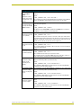
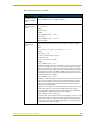
Configuration commands configure the manner in which the PosiTrack operates.
Configuration Commands
ACCEL
CONTROL=ON
Enables acceleration
control for pan/tilt
(default).
SEND_COMMAND CAM,"’ACCEL CONTROL=ON’"
Pan/Tilt movement speeds up and slows down based on PANACC, TILTACC,
and PRESET ACCEL values. This affects all pan/tilt movements and results in
smoother, dampened operation.
ACCEL
CONTROL=OFF
Syntax:
Disables acceleration
control for pan/tilt.
Pan/Tilt movement start and stop immediately. This results in more responsive
operation, although changes in speed may result in rough movements.
BUTTON PRESS
Syntax:
Executes a series of
preset 10-degree
movements for both
directions of pan/tilt.
SEND_COMMAND CAM,"’ACCEL CONTROL=OFF’"
SEND_COMMAND CAM,"’BUTTON PRESS’"
The PosiTrack moves up, home (stops), left, then stops at home. This is
designed to test the functionality of the PosiTrack’s field of movement.
CHAN PRESET=ON
Syntax:
Enables preset recalls
by turning ON the
preset channels
101-228.
The default mode of operation for these channels is feedback ONLY.
CHAN PRESET=OFF
Syntax:
Switches back
channels 101-228 to
feedback only mode.
(default).
CLEAR ERRORS
Clears all of the error
messages obtained by
using the DEVICE
STATUS command in
the Terminal Emulator
mode.
28
Syntax:
SEND_COMMAND CAM,"’CHAN PRESET=ON’"
SEND_COMMAND CAM,"’CHAN PRESET=OFF’"
Syntax:
SEND_COMMAND CAM,"’CLEAR ERRORS’"
Refer to the Diagnostic error values section on page 41 for detailed information.
AXB-PT10/15/30 PosiTrack Camera Controllers
Programming
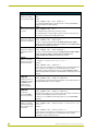
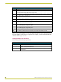
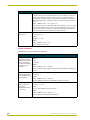
Configuration Commands (Cont.)
CLEAR HOME
Clears the current
home position and
goes to the default
setting and clears
presets.
CLEAR LIMIT ALL
Clears all of the limits.
CLEAR LIMIT DOWN
Clears the tilt-down
limit.
CLEAR LIMIT LEFT
Clears the pan-left limit.
CLEAR LIMIT RIGHT
Clears the pan-right
limit.
CLEAR LIMIT UP
Clears the tilt-up limit .
CURRENT SPEED
PRIORITY=CHANNEL
Changes the
operational mode of
channels 31, 32, 35,
and 36.
CURRENT SPEED
PRIORITY=LEVEL
Syntax:
SEND_COMMAND CAM,"’CLEAR HOME’"
This command also clears all presets.
Syntax:
SEND_COMMAND CAM,"’CLEAR LIMIT ALL’"
Syntax:
SEND_COMMAND CAM,"’CLEAR LIMIT DOWN’"
Syntax:
SEND_COMMAND CAM,"’CLEAR LIMIT LEFT’"
Syntax:
SEND_COMMAND CAM,"’CLEAR LIMIT RIGHT’"
Syntax:
SEND_COMMAND CAM,"’CLEAR LIMIT UP’"
Syntax:
SEND_COMMAND CAM,"’CURRENT SPEED PRORITY=CHANNEL’"
Does NOT allow pan/tilt movement from levels until channels 31, 32, 35 and 36
are turned Off.
Setting this priority puts the unit in CaMatrix compatible mode. The CaMatrix is a
third-party RS232 control program that runs on a PC.
Syntax:
SEND_COMMAND CAM,"’CURRENT SPEED PRORITY=LEVEL’"
Changes the operaAllows pan/tilt movement from levels even if these channels are still On.
tional mode of channels
Setting this priority makes the move at current speed channels operate like the
31, 32, 35, and 36.
other axis movement channels.
DEFAULT ACCEL
Sets the Pan and Tilt
acceleration to the
default value of 90
degrees/(second
squared).
FIND HOME
Syntax:
SEND_COMMAND CAM,"’DEFAULT ACCEL’"
Syntax:
Runs a series of pan/tilt
SEND_COMMAND CAM,"’FIND HOME’"
movements to
After the mechanical recalibration, the unit moves to the location set via the
recalibrate its
"SET HOME" command (if applicable).
mechanical home.
FOCUS PRESET=POS This is applicable only if the FOCUS SIGNAL=S command is in effect, and the
FOCUS switch is set to the S position (servomotor mode).
Sets the FOCUS
voltage output to recall
positional presets
(default).
Syntax:
SEND_COMMAND CAM,"’FOCUS PRESET=POS’"
The command for FOCUS output to servomotor mode or motor mode MUST be
configured to match the switch settings.
AXB-PT10/15/30 PosiTrack Camera Controllers
29
Programming
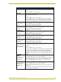
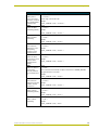
Configuration Commands (Cont.)
FOCUS
PRESET=SPEED
This is applicable only if the FOCUS SIGNAL=S command is in effect, and the
FOCUS switch is set to the S position (servomotor mode).
Sets the FOCUS
voltage output to recall
speed presets.
Syntax:
SEND_COMMAND CAM,"’FOCUS PRESET=SPEED’"
The command for FOCUS output to servomotor mode or motor mode MUST be
configured to match the switch settings.
FOCUS SIGNAL=M
This setting corresponds to the M position (motor mode) setting on the FOCUS
Sets the FOCUS output switch.
to be a motor output.
Syntax:
SEND_COMMAND CAM,"’FOCUS SIGNAL=M’"
The command for FOCUS signal must be configured to match the switch settings.
FOCUS SIGNAL=S
This setting corresponds to the FOCUS switch in the S position.
Sets the Focus output
to be a servomotor
output.
Syntax:
FP
Syntax:
Sets the lens’ Focus
mode to positional
(default).
FS
Sets the lens’ Focus
mode to speed.
SEND_COMMAND CAM,"’FOCUS SIGNAL=S’"
The command for FOCUS signal must be configured to match the switch settings.
SEND_COMMAND CAM,"’FP’"
This command can be used only for servomotor mode.
It causes a logic high (VREF-A) on Pin 7 of the lens control connector. This puts
a servomotor lens into positional focus mode.
Syntax:
SEND_COMMAND CAM,"’FS’"
This command can be used only for servomotor mode.
It causes a logic low (0 V) on Pin 7 of the lens control connector. This puts a servomotor lens into speed focus mode.
GET STATUS
(version 3.00 or
higher)
Displays the current
firmware version (Boot
and Download) on the
terminal along with
additional status
information.
The returned boot version is determined by checking the version in flash memory.
Syntax:
SEND_COMMAND CAM,"’GET STATUS’"
This command is issued from Terminal Emulator mode. When using a NetLinx
master, the ’MSG ON’ command must first be issued to see the status. Besides
the boot and download versions, it also displays the following information:
• Presets - predifined camera positions
• Channel preset - On or Off.
• Current speed - pan, tilt, zoom, focus, and iris speeds
• Current acceleration - a value between 0-255 on an acceleration curve applied
to the movement of the unit from one position to another.
• Acceleration control - On or Off.
• Mode - settings for the camera (servomotor or motor modes)
• Deviation - numeric value corresponding to how far-off from the center point of
your preset you want the camera to be when it finally stops on that preset.
• Speed Priority - level or channel
30
AXB-PT10/15/30 PosiTrack Camera Controllers
Programming
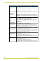
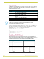
Configuration Commands (Cont.)
GET VERSION
(version 3.00 or
higher)
Displays the current
firmware version (Boot
and Download) on the
terminal.
The Boot version sent back is determined by checking the version in flash
memory.
Syntax:
SEND_COMMAND CAM,"’GET VERSION’"
This command is issued from Terminal Emulator mode. When using a NetLinx
master, the ’MSG ON’ command must first be issued to see the status.
HOME
If there is no user-defined HOME position, then the PosiTrack goes to the
Goes to the location set mechanical home position.
previously via the SET Syntax:
HOME command.
SEND_COMMAND CAM,"’HOME’"
This differs from the FIND HOME command in that HOME does not involve a
re-calibration of the PosiTrack’s mechanical position.
IA
Sets the lens’ Iris mode
to auto (default).
IL
Sets the lens’ Iris mode
to local.
IP
Sets the lens’ Iris mode
to positional (default).
Syntax:
SEND_COMMAND CAM,"’IA’"
This command causes pin 8 of the lens connector to float open. A Servomotor
lens will internally pull this signal high. In this mode, the iris signal from the PosiTrack (pin 5) will be ignored. Instead, the camera has full control of the lens iris,
typically used for Auto Iris mode (if the camera supports it).
Syntax:
SEND_COMMAND CAM,"’IL’"
This command applies Ground (0 V) to pin 8 of the lens connector. It allows iris
control from the PosiTrack.
Syntax:
SEND_COMMAND CAM,"’IP’"
This command can be used only for servomotor mode.
This command causes a logic high (VREF-A) on pin 9 of the lens control connector. This puts the servomotor lens into Positional Iris mode.
IRIS PRESET=POS
Sets the Iris voltage
output to recall
positional presets
(default).
IRIS PRESET=SPEED
Sets the Iris voltage
output to recall speed
presets.
This is only applicable if the IRIS SIGNAL=S command is in effect, and the IRIS
switch is set to the S position (servomotor mode).
Syntax:
SEND_COMMAND CAM,"’IRIS PRESET=POS’"
The command for IRIS output to servomotor mode or motor mode MUST be
configured to match the switch settings.
This is applicable only if the IRIS SIGNAL=S command is in effect, and the IRIS
switch is set to the S position (servomotor mode).
Syntax:
SEND_COMMAND CAM,"’IRIS PRESET=SPEED’"
The command for IRIS output to servomotor mode or motor mode MUST be
configured to match the switch settings.
IRIS SIGNAL=M
Sets the Iris output to
be a motor output.
This setting corresponds to the M position (motor mode) setting on the IRIS
switch.
Syntax:
SEND_COMMAND CAM,"’IRIS SIGNAL=M’"
The command for IRIS output to servomotor mode or motor mode MUST be
configured to match the switch settings.
AXB-PT10/15/30 PosiTrack Camera Controllers
31
Programming
Configuration Commands (Cont.)
IRIS SIGNAL=S
This setting corresponds to the S position (servomotor mode) setting on the IRIS
switch.
Sets the Iris output to
be a servomotor output. Syntax:
SEND_COMMAND CAM,"’IRIS SIGNAL=S’"
The command for IRIS output to servomotor mode or motor mode MUST be
configured to match the switch settings.
IS
Sets the lens’ Iris mode
to speed.
Syntax:
SEND_COMMAND CAM,"’IS’"
This command can be used only for servomotor mode.
This command causes a logic low (0 V) on pin 9 of the lens control connector.
This puts the servomotor lens into Speed Iris mode.
LENS=SERVO
Syntax:
Sets the lens settings to
SEND_COMMAND CAM,"’LENS=SERVO’"
servomotor mode style. This macro command sends the ZP, FP, IP, ZOOM PRESET=POS, ZOOM
SIGNAL=S, FOCUS PRESET= POS, FOCUS SIGNAL=S, IRIS PRESET=POS,
IRIS SIGNAL=S commands at one time.
LENS=STANDARD
Syntax:
Sets the lens settings to
SEND_COMMAND CAM,"’LENS=STANDARD’"
standard motor mode
This macro command sends the ZS, FS, IS, ZOOM PRESET=SPEED, ZOOM
style.
SIGNAL=M, FOCUS PRESET= SPEED, FOCUS SIGNAL=M, IRIS
PRESET=SPEED, IRIS SIGNAL=M commands at one time.
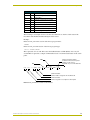
PANACC
Sets the acceleration
rate of the pan axis, for
manual movements.
Syntax:
"'PANACC <acceleration rate 0-127>’"
Examples:
SEND_COMMAND CAM,"’PANACC22’"
A value of zero sets acceleration to 2.25 degrees per second squared and 127
sets acceleration to 135 degrees per second squared. There is a linear
relationship for values between 0 and 127. The command DEFAULT ACCEL
sets both the pan and tilt acceleration to the default value of 90 degrees/(second
squared).
POWER UP
HOME=ON
Enables the unit to reestablish the mechanical HOME position
position at each
power-up (default).
Syntax:
SEND_COMMAND CAM,"’POWER UP HOME=ON’"
The unit performs a mechanical "homing" calibration on power-up. This process
takes approximately 30 seconds to complete.
POWER UP
HOME=OFF
Syntax:
Prevents the
mechanical HOME
process at power-up.
During the power-up process, the unit stays in the same position it was before it
lost power. It is immediately ready for use in this mode.
PRESET ACCEL
Syntax:
Sets the acceleration
rate of the pan and tilt
axes for preset recall
movements.
SEND_COMMAND CAM,"’POWER UP HOME=OFF’"
In order to force a recalibration and homing sequence, use the FIND HOME
command.
SEND_COMMAND CAM,"’PRESET ACCEL <acceleration rate
0-127>’"
Examples:
SEND_COMMAND CAM,"’PRESET ACCEL 22’"
A value of zero sets acceleration to 2.25 degrees per second squared and 127
sets acceleration to 135 degrees per second squared. There is a linear
relationship for values between 0 and 127.
32
AXB-PT10/15/30 PosiTrack Camera Controllers
Programming
Configuration Commands (Cont.)
READ ALL
Forces the device to read and update levels to the Central Controller.
Syntax:
SEND_COMMAND CAM,"’READ ALL’"
RUN TESTS
Runs and checks error values 244 and 245 to see if the gears are properly
aligned to their respective grooves.
Syntax:
SEND_COMMAND CAM,"’RUN TESTS’"
Refer to the Diagnostic error values section on page 41 for more detailed
information. Make sure there are no obstructions while the PosiTrack performs
the full range of the following movements: Up, Down, Home, Left, Home.
SET HOME
Sets a new home
position.
SET LIMIT DOWN
Sets the down tilt limit
value given.
SET LIMIT LEFT
Sets the left pan limit
value given.
SET LIMIT RIGHT
Sets the right pan limit
value given.
SET LIMIT UP
Syntax:
SEND_COMMAND CAM,"’SET HOME’"
Warning! This command clears all presets.
Syntax:
SEND_COMMAND CAM,"’SET LIMIT DOWN’"
Warning! This command clears all presets.
Syntax:
SEND_COMMAND CAM,"’SET LIMIT LEFT’"
Warning! This command clears all presets.
Syntax:
SEND_COMMAND CAM,"’SET LIMIT RIGHT’"
Warning! This command clears all presets.
Syntax:
Sets the up tilt limit
value given.
Warning! This command clears all presets.
TILTACC
Syntax:
Sets the acceleration
rate of the tilt axis, for
manual movements.
SEND_COMMAND CAM,"’SET LIMIT UP’"
"’TILTACC <acceleration rate 0-127>’"
Examples:
SEND_COMMAND CAM,"’TILTACC103’"
A value of zero sets acceleration to 2.25 degrees per second squared and 127
sets acceleration to 135 degrees per second squared. There is a linear
relationship for values between 0 and 127. The command DEFAULT ACCEL
sets both the pan and tilt acceleration to the default value of 90 degrees/(second
squared).
TILT CURVE=
NORMAL
Adjusts Tilt Up/Down
speed curves for
normal mounting
position.
TILT CURVE= INVERT
Adjusts Tilt Up/Down
speed curves for
inverted mounting
position.
Syntax:
SEND_COMMAND CAM,"’TILT CURVE=NORMAL’"
This keeps the up and down tilts moving at the same rate for a given speed.
(Added v1.10) Sets the tilt curve to normal, for normal installation position.
This command DOES NOT reverse the direction of the pan/tilt motors.
Syntax:
SEND_COMMAND CAM,"’TILT CURVE=INVERT’"
This keeps the up and down tilts moving at the same rate for a given speed.
(Added v1.10)
Sets the tilt curve to inverted, for inverted installation position. This command
reverses the direction of the tilt motor.
AXB-PT10/15/30 PosiTrack Camera Controllers
33
Programming
Configuration Commands (Cont.)
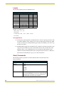
ZAP!
Syntax:
Initializes all memory in
SEND_COMMAND CAM,"’ZAP!’"
the unit.
This includes speed settings, deviation settings, configuration settings, and all
presets.
Warning! This command clears all user-defined settings.
ZOOM PRESET=POS
Sets the Zoom voltage
output to recall
positional presets
(default).
Syntax:
SEND_COMMAND CAM,"’ZOOM PRESET=POS’"
This is applicable only if the ZOOM SIGNAL=S command is in effect, and the
ZOOM switch is set to the S position (servomotor mode). The command for
ZOOM output to servomotor mode or motor mode MUST be configured to match
the switch settings.
ZOOM
PRESET=SPEED
Syntax:
Sets the Zoom voltage
output to recall speed
presets.
This is applicable only if the ZOOM SIGNAL=S command is in effect, and the
ZOOM switch is set to the S position (servomotor mode). The command for
ZOOM output to servomotor mode or motor mode MUST be configured to match
the switch settings.
ZOOM SIGNAL=S
Syntax:
Sets the Zoom output
to be a servomotor
output.
ZOOM SIGNAL=M
Sets the Zoom output
to be a motor output.
ZP
Sets the lens’ Zoom
mode to positional
(default).
ZS
Sets the lens’ Zoom
mode to speed.
SEND_COMMAND CAM,"’ZOOM PRESET=SPEED’"
SEND_COMMAND CAM,"’ZOOM SIGNAL=S’"
This setting corresponds to the S position (servomotor mode) setting on the
ZOOM switch. The command for ZOOM output to servomotor mode or motor
mode MUST be configured to match the switch settings.
Syntax:
SEND_COMMAND CAM,"’ZOOM SIGNAL=M’"
This setting corresponds to the M position (motor mode) setting on the ZOOM
switch. The command for ZOOM output to servomotor mode or motor mode
MUST be configured to match the switch settings.
Syntax:
SEND_COMMAND CAM,"’ZP’"
This command can be used only for servomotor mode.
This command causes a logic high (VREF-A) on pin 6 of the lens control connector. This puts the servomotor lens into Positional Zoom mode.
Syntax:
SEND_COMMAND CAM,"’ZS’"
This command can be used only for servomotor mode.
This command causes a logic low (0 V) on pin 6 of the lens control connector.
This puts the servomotor lens into Speed Zoom mode.
34
AXB-PT10/15/30 PosiTrack Camera Controllers
Programming
Channel Commands
Use channel commands to program pan/tilt, servomotor positional, servomotor speed, and motor
mode functions.
Pan/tilt functions
Pan/Tilt Functions
Channel
State
Function
31
On
Pan right at current speed
32
On
Tilt down at current speed
35
On
Pan left at current speed
36
On
Tilt up at current speed
40
On
Pan right at maximum speed (100%)
41
On
Pan left at maximum speed (100%)
42
On
Tilt down at maximum speed (100%)
43
On
Tilt up at maximum speed (100%)
44
On
Pan right at medium speed (50%)
45
On
Pan left at medium speed (50%)
46
On
Tilt down at medium speed (50%)
47
On
Tilt up at medium speed (50%)
Servomotor mode lens functions
Servomotor Mode Lens Functions
Channel
State
Function
1
On
Iris (+) at current rate
3
On
Zoom (+) at current rate (increases output voltage)
4
On
Focus (+) at current rate
5
On
Iris (-) at current rate
7
On
Zoom (-) at current rate (decreases output voltage)
8
On
Focus (-) at current rate
10
On
Iris (+) at maximum speed
12
On
Zoom (+) at maximum speed (output minimum voltage)
13
On
Focus (+) at maximum speed
14
On
Iris (-) at maximum speed
16
On
Zoom (-) at maximum speed (output maximum voltage)
17
On
Focus (-) at maximum speed
18
On
Iris (+) at 50% speed
20
On
Zoom (+) at 50% speed
21
On
Focus (+) at 50% speed
22
On
Iris (-) at 50% speed
24
On
Zoom (-) at 50% speed
25
On
Focus (-) at 50% speed
AXB-PT10/15/30 PosiTrack Camera Controllers
35
Programming
Motor mode lens functions
Motor Mode Lens Functions
Channel
State
Function
1
On
Iris (+) at current speed
3
On
Zoom (+) at current speed (increases output voltage)
4
On
Focus (+) at current speed
5
On
Iris (-) at current speed
7
On
Zoom (-) at current speed (decreases output voltage)
8
On
Focus (-) at current speed
10
On
Iris (+) at maximum speed
12
On
Zoom (+) at maximum speed (output minimum voltage)
13
On
Focus (+) at maximum speed
14
On
Iris (-) at maximum speed
16
On
Zoom (-) at maximum speed (output maximum voltage)
17
On
Focus (-) at maximum speed
18
On
Iris (+) at 50% speed
20
On
Zoom (+) at 50% speed (half speed)
21
On
Focus (+) at 50% speed
22
On
Iris (-) at 50% speed
24
On
Zoom (-) at 50% speed
25
On
Focus (-) at 50% speed
Preset functions
Preset Functions
Channel
State
Function
50
On
Pan is seeking POT (Encoder) preset (status only)
51
On
Tilt is seeking POT (Encoder) preset (status only)
52
On
Zoom is seeking POT preset (status only)
53
On
Focus is seeking POT preset (status only)
101-227
On
Recall preset 1–127 or currently at preset 1–127.
The unit supports presets 1–255 but only presets 1–127
can be recalled using channel On commands. Presets
128–255 must be recalled with Send_Command "RP".
There are no feedback channels for presets
128-255.
CHAN PRESET=ON Send_Command MUST be issued
to enable this feature (see page 28).
36
AXB-PT10/15/30 PosiTrack Camera Controllers
Programming
Status Channels
Channel
State
Function
29
On
Unit is panning
30
On
Unit is tilting
95
On
Unit has found its max pan left limit
96
On
Unit has found its max pan right limit
97
On
Unit has found its max tilt up limit
98
On
Unit has found its max tilt down limit
228
On
Unit has found its HOME position
248
On
Unit is finding HOME position
The following is an example of how to use the above functions to obtain a visual status of the
movement of the PosiTrack without being in visual contact.
Example:
In the DEFINE_VARIABLE section of the Axcess program enter:
FLASH
In the DEFINE_PROGRAM section of the Axcess program type:
wait 5 Flash=!Flash
The 5 represents 1/2 a second. This causes the feedback button to blink (Flash) once every 1/2
second. FIG. 25 represents a sample command that creates a movement status button on the touch
panel.
AND
Flashes the button until the
PosiTrack unit reaches the preset
number - in this case 51.
Required only once in the main line.
OR
[TP, 81] = ([CAM, 101] || (FLASH && [CAM, 51]))
Channel number
Device number assigned to the PosiTrack unit
Channel number
Device assigned to touch panel or switch panel
FIG. 25 Send_Command for a status movement button
AXB-PT10/15/30 PosiTrack Camera Controllers
37
Programming
Levels
The following table lists the Axcess/NetLinx levels.
Levels
Level values
Axcess/NetLinx level
Range
Direction
1
Pan
0 - 255
To PT
2
Tilt
0 - 255
To PT
3
Zoom
0 - 255
To PT
4
Focus
0 - 255
To PT
5
Pan Feedback
0 - 65535
From PT
6
Tilt Feedback
0 - 65535
From PT
7
Zoom POT Feedback
0 - 65535
From PT
8
Focus POT Feedback
0 - 65535
From PT
Example of sending levels:
SEND_LEVEL 90,1,200
90=DEVICE
1=FUNCTION (PAN, TILT, ZOOM, FOCUS)
200=LEVEL
Level applications
Touch panel joystick application: PosiTrack Levels 1 and 2 are speed type levels for both
pan and tilt. Sending a value of 0 (zero) moves the axis full speed in one direction; while
a value of 255 moves it at full speed in the opposite direction. Sending a 127 value, stops
the units’ movement.
Pan/Tilt feedback application: PosiTrack Levels 5 and 6 are positional levels with a value
range of 0 - 65535. These two levels can be used in Axcess code to monitor the actual
pan/tilt positions or store additional presets. To recall presets in this manner, use the
’GxLxxxx’ Send Command with the values stored previously from level 5 or 6. Refer to
the Positional Commands table on page 39 for more information.
Send_Commands
The following table lists parameters for the PosiTrack Camera Controllers Positional
Send_Commands.
Parameters - Send_Commands
Parameters
Description
Outputs
1—PAN
2—TILT
3—ZOOM
4—FOCUS
5—IRIS
Level
0 (lowest) to 255 (highest) or 0% to 100%
On pan, tilt, and PWM drives for zoom, focus, and iris, level 128
will be OFF. Level 129 and above are for the forward direction.
Level 127 and below are for the reverse direction.
38
AXB-PT10/15/30 PosiTrack Camera Controllers
Programming
Parameters - Send_Commands (Cont.)
Parameters
Description
Time (optional)
If specified, 0 to 255 in tenths of a seconds; if not specified, at
current rate.
Position
0 to 255; value of POT input. Corresponds to a position of the
unit. 0 is one end of the POT and 255 is the other end. Not
directly related to an output level voltage.
0 to 65535 when using the 'AD MODE x 10' command, or for pan/
tilt commands. Corresponds to a position of the unit. 0 is one end
of the POT and 65,535 is the other end. Not directly related to an
output level voltage.
Speed
0 to 127; where 0 is slowest and 127 is fastest (default).
Deviation
0 to 127; where 0 is most accurate but can have some jitter.
Default is 2, which means the position can be within +/- 2 from the
specified position.
Distance
0 to 127; distance from the specified position.
Ramp Time
1 to 255; time in 10ms increments that it takes the motor drives to
ramp up to speed.
The following table lists parameters for the PosiTrack Camera Controllers Positional Commands.
Positional Commands
GAS
This command can be used for motor mode and servomotor speed modes.
Sets the output to slow
down within the
specified distance of
the specified position
for future 'GxLxxx'
commands.
Syntax:
"’G<output>A<distance>S<speed>’"
Variables (See Parameters - Send_Commands section on page 38):
G - output = 1 - 4
A - distance = 0 - 127
S - speed = 0 - 127
Example:
SEND_COMMAND CAM,"’G1A5S20’"
Sets PAN to speed 20 when within 5 of the specified position for future 'G1Lxxx'
commands.
GD
This command can be used for motor mode and servomotor speed/positional modes.
Sets the current
maximum position
deviation for future
position ('GxLxxx')
commands.
Syntax:
"’G<output>D<deviation>’"
Variables (See Parameters - Send_Commands section on page 38):
G - output = 1 - 4
D - deviation = 0 - 127
Example:
SEND_COMMAND CAM,"’G1D4’"
Sets PAN deviation to 4 for future 'G1Lxxx' commands. Output will stop when it is
within 4 of the specified position.
AXB-PT10/15/30 PosiTrack Camera Controllers
39
Programming
Positional Commands (Cont.)
GL
This command can be used for all modes.
Turns on the specified
output at the current
speed until the
specified position (as
read by the Pan or Tilt
encoder) is reached.
Syntax:
"’G<output>L<position>’"
Command forces output to go to a preset position using the POT input as a
reference.
Variables (See Parameters - Send_Commands section on page 38):
G - output = 1 - 2
L - position = 0 - 65535
Example:
SEND_COMMAND CAM,"’G1L32000’"
Sets PAN to search for position 32000 as referenced by the Pan or Tilt encoder.
GL
This command can be used for motor mode and servomotor speed modes.
Turns on the specified
output at the current
speed until the
specified position as
read by the POT input
is reached.
Syntax:
"’G<output>L<position>’"
Command forces output to go to a preset position using the POT input as a
reference.
Variables (See Parameters - Send_Commands section on page 38):
G - output = 3 - 4
L - position = 0 - 65535
Example:
SEND_COMMAND CAM,"’G3L10000’"
Sets ZOOM to search for position 10000 as referenced by the ZOOM POT input.
GS
This command is used for motor mode and servomotor speed mode applications.
Sets the current speed
for future and current
Send_Commands and
channel commands.
Syntax:
"’G<output>S<speed>’"
Variables (See Parameters - Send_Commands section on page 38):
G - output = 1 - 5
S - speed = 0 - 127
Example:
SEND_COMMAND CAM, "’G1S64’"
Sets PAN to speed 64 (50%) for current and future commands.
The G1 and G2 commands are used for all modes. The G3, G4, and G5 commands
are for the Motor and Servomotor Speed modes only.
PLT
This command can be used only for servomotor positional mode applications.
Syntax:
Ramps specified
output voltage from
"’P<output>L<level >[T<time >]’"
current level to a
Variables
(See Parameters - Send_Commands section on page 38):
specified level or
percentage at the
P - output = 3 - 5
current rate or
L - level = 0 - 255 or 1 - 100%
optionally in a specified
T - time = 0 - 255 (in tenths of a second)
amount of time.
Example:
SEND_COMMAND CAM,"’P3L50%’"
Ramps zoom output to 50% (mid-voltage) at current rate.
SEND_COMMAND CAM,"’P4L255T30’"
Ramps FOCUS output to 255 in 3 seconds.
40
AXB-PT10/15/30 PosiTrack Camera Controllers
Programming
Positional Commands (Cont.)
PR
This command can be used for servomotor positional mode applications.
Syntax:
Sets the ramp rate of
the specified output
"’P<output>R<time>[U|D]’"
voltage where time is
the time to ramp the full Variables (See Parameters - Send_Commands section on page 38):
range both down to up
P - output = 3 - 5
and up to down or
R - time = 0 - 255
optionally just down to
U\D = Up or Down
up or up to down.
Example:
SEND_COMMAND CAM,"’P3R50’"
Sets zoom ramp rate to 5 seconds full range for “down to up” and “up to down.”
"’P4R75U’"
Sets the Focus ramp rate to 7.5 seconds full range for Down to up. This command
can be used for motor and servomotor positional mode applications.
"’P5R25D’"
Sets the Iris ramp rate to 2.5 seconds full range for up to down only.
Diagnostic error values
In the Terminal Emulator of the AxcessX or NetLinx Studio program, you can use the Device
Status command to diagnose any problems with the PosiTrack Controller. The following is an
example of how to diagnose problems using the DEVICE STATUS and CLEAR ERRORS commands
to obtain error values that can help you better track any problems.
1. Turn the PosiTrack Controller On and make sure the proper connections are plugged into the
unit. Open Terminal Emulator.
2. Type DEVICE STATUS 90 in the Terminal Emulator. The 90 used in this example is the
Device Number assigned to the PosiTrack.
3. Give the Emulator at least 5 seconds to respond with an error value, if any exists.
4. If there is an error present, the emulator displays the number 230 and other values, listed in
the Error Values and Descriptions table on page 42, that correspond to particular problems
encountered during the diagnostic cycle.
5. Type SEND_COMMAND 90, "'CLEAR ERRORS'" to clear the errors in the PosiTrack unit
after the problem is resolved. This command clears all the error messages that may have
appeared while you were diagnosing problems.
6. Turn the PosiTrack Controller Off and fix the problem.
7. Turn the unit On once the problem has been fixed.
8. Repeat steps 3 through 7 until the problem no longer exists.
When using version 2.04 firmware or higher, the PosiTrack stops all pan and tilt
operations if an error is found. Correct the source of the error and cycle power on the
unit to resume operation. The error channels remain On until a CLEAR ERRORS or
ZAP! command is sent.
The following table lists the error values you can get when diagnosing any problem.
AXB-PT10/15/30 PosiTrack Camera Controllers
41
Programming
Error Values and Descriptions
Error
Description
230
Shows there is an error on the system. This value always appears in conjunction with another
number. It acts as a precursor to any other error messages, as an announcement that an error has
been found and the following values are the errors found.
240
Shows that there is a problem with the Pan Encoder on the PosiTrack. The encoder is a device that
counts the revolutions of the pan motor.
241
Shows that there is a problem with the Tilt Encoder on the PosiTrack. The encoder is a device that
counts the revolutions of the tilt motor.
242
Shows that there is a problem with the Pan Optical reader on the PosiTrack. The reader is a device
that detects the home position of the pan gear.
243
Shows that there is a problem with the Tilt Optical reader on the PosiTrack. The reader is a device
that detects the home position of the tilt gear.
244
Shows that there is a Worm Eccentric error (pan) on the system. This error occurs when the worm
gear is not fitting properly along the pan’s gears.
245
Shows that there is a Worm Eccentric error (tilt) on the system. This error occurs when the worm
gear is not fitting properly along the tilt’s gears.
246
Shows that the pan stalled. Occurs when the pan motor locks up for more than 5 seconds.
247
Shows that the tilt stalled. Occurs when the tilt motor locks up for more than 5 seconds.
If there are any errors found, the 230 error value displays that there is an error, and is then followed
by another number to indicate the precise problem. For example, a problem with the Pan Encoder
will return the message: 230, 240.
Preset parameters and commands
The following table lists the preset parameters.
Preset Parameters
42
Preset
1-255
TIME: (Optional)
If specified, 0 to 255 in tenth seconds. If not specified, at current rate. Used for voltage
outputs. Used only for Recall Preset.
SPEED: (Optional)
0 to 127. 0 is slowest and 127 if fastest. If not specified, at current speed. Used only for
Recall Preset.
AXB-PT10/15/30 PosiTrack Camera Controllers
Programming
The following table lists preset commands.
Preset Commands
CANCEL PRESET
Immediately stops any
active preset recall in
motion.
CP
Clears a preset from
memory.
Examples:
SEND_COMMAND CAM, "’CANCEL PRESET’"
Syntax:
"’CP<preset>’"
Variables:
preset = 1 - 255
Examples:
SEND_COMMAND CAM, "’CP1’"
Clears Preset 1.
SEND_COMMAND CAM, "’CP100’"
Clears Preset 100.
RP
Recalls a stored
preset.
Optional parameters include ramp time for servomotor positional presets, motor
mode, servomotor speed mode, and inclusion (+ default) or exclusion (-) of iris in
preset.
Syntax:
"’RP<preset>[T<time>][S<speed>][I<- or +>]’"
Variables:
RP - preset = 1 - 255
T - time = 0 -255 (in tenths of a second)
S - speed = 0 - 127
I - iris = "-" to exclude, "+" to include
Examples:
SEND_COMMAND CAM,"’RP1’"
Recalls preset 1. Same as turning on channel 101. If any are in servomotor positional
mode, the current voltages for zoom, focus, and/or iris will be ramped to the preset
voltages at the current speed. If any are in servomotor speed mode, the motor drive
outputs for zoom and/or focus outputs will run at their preset-defined speeds until the
preset positions are reached on the POTs. Regardless of the preset type used, the
pan/tilt drives will run at their current speeds until the proper positions are reached on
their POTs. Channel 101 is turned On.
SEND_COMMAND CAM,"’RP1I-’"
Recalls preset 1. Same as turning on channel 101. If any are in servomotor positional
mode, the current voltages for zoom, and /or focus iris will be ramped to the preset
voltages at the current speed. If any are in speed mode, the motor drive outputs for
zoom and/or focus outputs will run at their preset-defined speeds until the preset
positions are reached on the POTs.
Regardless of the preset type used, the pan/tilt drives will run at their current speeds
until the proper positions are reached on their POTs. Channel 101 is turned on.
The iris signal will be excluded from the preset recall and will not be included in displaying feedback as to whether the preset has been completed.
SEND_COMMAND CAM,"’RP10T100’"
Recalls preset 10. If any are in positional mode, voltage outputs for zoom, focus, and/
or iris will ramp to position in 10 seconds. If any are in speed mode, the motor drive
outputs for zoom and/or focus outputs will run at their preset-defined speeds until the
preset positions are reached on the POTs. Pan/tilt outputs use current speed. Turns
on channel 110 when preset 10 is reached.
AXB-PT10/15/30 PosiTrack Camera Controllers
43
Programming
Preset Commands (Cont.)
SEND_COMMAND CAM,"’RP10S64’"
Recalls preset 10. If any are in positional mode, the current voltages for zoom, focus,
and/or iris will be ramped to the preset voltages at the current speed. If any are in
speed mode, the motor drive outputs for zoom and/or focus will move at half speed
(64). Pan/tilt outputs will move at half speed. Turns on channel 110 when preset 10 is
reached.
SEND_COMMAND CAM,"’RP10T100S64’"
Recalls preset 10. If any are in positional mode, voltage outputs for zoom, focus, and/
or iris will ramp to position in 10 seconds. If any are in speed mode, the motor drive
outputs for zoom and/or focus will move at half speed (64). Pan/tilt outputs will use
current speed. Turns on channel 110 when preset 10 is reached.
SP
Syntax:
Store preset.
"’SP<preset>’"
Variables:
SP- preset = 1 - 255
Example:
SEND_COMMAND CAM,"’SP1’"
Stores current values to Preset 1.
RS-232 commands
The following table lists the RS-232 commands.
RS-232 Commands
B9MON
Enables the special 9
data bits with 1 stop bit
mode, and overrides
the DIP switch settings
for data, stop, and
parity bits.
The baud rate is locked on at the current DIP switch setting upon issuance of this
command.
Syntax:
"’B9MON’"
Example:
SEND_COMMAND CAM,"’B9MON’"
Sets the special 9 bits with 1 stop bit mode, and overrides the DIP switch settings on
the device.
B9MOFF
Sets data bits mode to
normal with DIP switch
setting (default).
Syntax:
"’B9MOFF’"
Example:
SEND_COMMAND CAM,"’B9MOFF’"
Resets the data bits mode back to the DIP switch settings on the device.
CHARD
Syntax:
Sets the delay time
between all
transmitted characters
to the device.
Variables:
"’CHARD-<time>’"
time = 0 - 255 in 100 microsecond increments
Example:
SEND_COMMAND CAM,"’CHARD-10’"
Sets 1 ms delay between all transmitted characters.
44
AXB-PT10/15/30 PosiTrack Camera Controllers
Programming
RS-232 Commands (Cont.)
CTSPSH
Enables pushes,
releases, and status
information on channel
255 for CTS hardware
handshake input.
HSOFF
Disables hardware
handshaking (default).
Syntax:
"’CTSPSH’"
If CTS is high, channel 255 is On.
Example:
SEND_COMMAND CAM,"’CTSPSH’"
Syntax:
"’HSOFF’"
Example:
SEND_COMMAND CAM,"’HSOFF’"
HSON
Syntax:
Enables hardware
handshaking.
Example:
"’HSON’"
SEND_COMMAND CAM,"’HSON’"
RXCLR
Clears characters
waiting in the receive
buffer pending
transmission to the
Central Controller.
RXOFF
Disables the device
from passing received
characters to the
Central Controller
(default).
RXON
Syntax:
"’RXCLR’"
Example:
SEND_COMMAND CAM,"’RXCLR’"
Syntax:
"’RXOFF’"
Example:
SEND_COMMAND CAM,"’RXOFF’"
Syntax:
Enables the device to
send incoming
(received) characters
to the Central Controller.
Example:
TXCLR
Syntax:
"’RXON’"
This command is automatically sent by the master when a 'CREATE_BUFFER'
program instruction is executed.
SEND_COMMAND CAM,"’RXON’"
Clears characters
waiting in the transmitout buffer, and stop
transmissions.
Example:
XOFF
Syntax:
Disables software
handshaking (default).
"’TXCLR’"
SEND_COMMAND CAM,"’TXCLR’"
"’XOFF’"
Example:
SEND_COMMAND CAM,"’XOFF’"
XON
Syntax:
Enables software
handshaking.
Example:
"’XON’"
SEND_COMMAND CAM,"’XON’"
AXB-PT10/15/30 PosiTrack Camera Controllers
45
Programming
RS-232 Send_Strings
PosiTracks have special Send_String escape sequences. If any of the three-character combinations
listed below are found anywhere within a Send_String program instruction, they are treated as a
command and not the literal characters.
RS-232 Send_Strings
"'27,18,0'"
Clears the ninth data bit to 0 for all subsequent characters to be transmitted. It is used
in conjunction with the 'B9MON' command.
"'27,18,1'"
Sets the ninth bit to 1 for all subsequent characters to be transmitted. It is used in
conjunction with the 'B9MON' command.
"'27,19,<time>'"
Inserts a delay before the next character to be transmitted.
Variable:
time = 1 - 255 in 1 millisecond increments
"'27,20,0'"
De-asserts RTS hardware handshake output high.
"'27,20,1'"
Asserts an RTS hardware handshake output low.
In 485 mode, if the delay escape code characters are the last in the Tx buffer, the 485
Tx output will tri-state at the beginning of the delay.
If you need to send a string containing sequences "27,17," "27,18," "27,19," or "27,20," use two
Send_String commands. The first containing characters up to and including "27", the second
beginning with "17", "18", "19", or "20", and all subsequent characters.
To send the string "$1B,'C',0,27,17,13", use:
{
SEND_STRING <dev>,’"$1B,'C',0,27"’
SEND_STRING <dev>,’"17,13"’
}
Stand-Alone RS-232 Protocol
The stand-alone RS-232 protocol (in the General Format table) is used when the PosiTrack is
configured for external stand-alone RS-232 mode. See the Pre-Installation and Installation sections
for details on setting internal jumpers, device number DIP switch, and RS-232 wiring.
General Format
Byte No.
Attention Byte
2
Command #
3
Data
Last
RS-232
Levels
46
Type
1
Checksum, sum of all bytes Mod 256
Level
Range
Direction
0
PAN
0-255
To PT
1
TILT
0-255
To PT
2
ZOOM
0-255
To PT
3
FOCUS
0-255
To PT
AXB-PT10/15/30 PosiTrack Camera Controllers
Programming
General Format (Cont.)
Byte No.
Type
Range
Direction
4
Pan Feedback
0-65535
From PT
5
Tilt Feedback
0-65535
From PT
6
Zoom Pot Feedback
0-65535
From PT
7
Focus Pot Feedback
0-65535
From PT
RS-232 Levels that are valid <LEVEL NO> are 0-7.
The following table lists the request functions sent to PosiTrack units.
Request Functions Sent to the PosiTrack Unit
Functions
Syntax
Channel On/Off
'*' <1>
<0> <CHANNEL> <STATUS> <CHECKSUM>
Status 1 -> turn on channel status 0 -> turn off channel
Set level (byte)
'*' <3>
<0> <LEVEL NO(0-3 valid)><LEVEL> <CHECKSUM>
Send string
'*' <4>
<0> <# BYTES> <STRING> <CHECKSUM>
Send command
'*' <5>
<0> <# BYTES> <STRING> <CHECKSUM>
Get channel status
'*' <6>
<0> <STATUS CHANNELS> <CHECKSUM>
Get level status
'*' <7>
<0> <LEVEL, (4-7 valid)> <CHECKSUM>
Get bus status
'*' <8>
<CHECKSUM>
Get device(s)
'*' <9>
<CHECKSUM>
Set response mask
'*' <10> <MASK1> <MASK2> <CHECKSUM>
Send all on channels
'*' <11> <0> <CHECKSUM>
Send all levels
'*' <12> <0> <CHECKSUM>
Set level (word)
'*' <13> <0> <LEVEL NO><LEVEL_H><LEVEL_L><CHECKSUM>
Stand alone baud rate
'*' <14> <0 or 1> <CHECKSUM>
A value of 0 sets the rate to 9600. A value of 1 enters a baud rate of 38.4 KB.
This table lists the return/response strings from the PosiTrack units.
Return/Respond Strings from the PosiTrack Units
Function
Channel status
Syntax
'&' <1> <0> <CHANNEL> <STATUS> <CHECKSUM>
Status 1 = Turn on channel
Status 0 = Turn off channel
Change level (byte)
'&' <2> <0> <LEVEL NO> <LEVEL> <CHECKSUM>
Receive string
'&' <3> <0> <# BYTES> <STRING> <CHECKSUM>
Receive command
'&' <4> <0> <# BYTES> <STRING> <CHECKSUM>
Bus led status
'&' <5> <STATUS> <CHECKSUM>
Bus status
'&' <6> <STATUS> <CHECKSUM>
When AXlink is reset, BUS STATUS is sent without being queried.
When AXlink goes back online, BUS STATUS is sent again.
Device list
'&' <7> <# DEVICES> <DEVICES> <CHECKSUM>
Change level (word)
'&' <8> <0> <LEVEL NO> <LEVEL_H> <LEVEL_L>
<CHECKSUM>
AXB-PT10/15/30 PosiTrack Camera Controllers
47
Programming
Response mask
Data is automatically sent if the PosiTrack units receive a change request. The response mask
should be disabled if the change request data is not used. Bits in the response mask
(the Return/Respond Strings from the PosiTrack Units table) turn data off.
(1=ON)
DATA SENT
(0=OFF)
DATA NOT SENT
Response Mask
Bit
Data Controlled
Default
RECEIVE STRING
1
6
RECEIVE COMMAND
1
5
CHANNEL CHANGE
1
4
LEVEL CHANGE
1
3
BUS LED
0
2
(future)
0
1
(future)
0
0 (lsb)
(future)
0
7 (msb)
(future)
0
6
(future)
0
5
(future)
0
4
(future)
0
3
(future)
0
2
(future)
0
First byte (MASK1)
7 (msb)
Second byte (MASK2)
48
1
(future)
0
0 (lsb)
(future)
0
AXB-PT10/15/30 PosiTrack Camera Controllers
Upgrading the Firmware
Upgrading the Firmware
Upgrading the Firmware Using NetLinx Studio
The NetLinx Studio application can perform firmware upgrades for both Axcess and
NetLinx devices using the options in the NetLinx Studio Firmware sub-menu.
Upgrading Firmware on Axcess Systems
1. Choose Tools > Firmware > Download to Axcess Device to open the Axcess Firmware
Download dialog.
The default Baud Rate for Axcess is 38400 baud and for NetLinx is 38400 baud.
2. Adjust the Comm Settings, if necessary:
a. Click Settings to open the Communication Setting dialog and set the properties for the
desired platform.
b. Select the Communications Port and Baud Rate (FIG. 26).
FIG. 26 Setting Comm Settings and Baud Rates
c. Click OK to accept the changes and return to the Axcess Firmware Download dialog.
3. Click Browse to navigate to the directory containing the firmware files. Once a directory
containing one or more .TSK files is specified, a list of available .TSK files is displayed in the
upper table in this dialog.
4. Click Query Online Devices to populate the on-line device list.
5. Select the desired .TSK file from the list of available files.
6. Select the target AXlink device from the list of online devices in the lower-left table.
7. Click Download to open the Confirm Communication Settings dialog, where you can review
and confirm your Comm Settings and Target Device information before the download begins.
Click Cancel to return to the Select Axcess Firmware File dialog, to edit these settings
(if necessary).
AXB-PT10/15/30 PosiTrack Camera Controllers
49
Upgrading the Firmware
Click OK to confirm the Comm Settings and Target Device information, and download
the selected .TSK file to the specified device using the selected communications port.
8. The File Transfer dialog shows the progress of the download. Click Cancel to cancel the
download.
Canceling the firmware download in mid-progress can damage the on-board
firmware.
9. Once the .TSK file has been downloaded, the device AXlink LED will begin to flash
repeatedly for about 6 seconds while the on-board firmware is stored and updated.
Afterwards, the AXlink LED blinks once per second (to indicate proper communication) and
the unit runs a self-calibration routine.
Upgrading the Firmware Using SOFTROM
The 16-bit Softrom application is only used when working with Axcess masters.
Your PC must be connected to the PROGRAM DB-9 connector on the Axcess Controller using a
Programming Cable in order to upgrade the firmware in the panel.
If power is lost during the download process, the unit powers up with the same set of code it had
prior to the download. There is a small window during which a loss of power can be catastrophic. If
power is lost between the erase of flash memory and the completion of copying the new boot code
from RAM to flash memory, the unit will not operate at all when power returns.
If you have not already installed the SOFTROM program, do so by following the steps contained on
the AMX Control Disc.
Configuration
To configure the communication setting for the SOFTROM program:
1. Press F1, the Configuration screen appears.
2. Using the up/down arrow keys, select the communications port you are using to interface with
the controller and press ENTER.
3. Using the right arrow key, move to the BAUD RATE column. Then, use the up/down arrow
keys to select the interface communications speed and press ENTER. Be sure the BAUD
RATE selections match the setting on the Controller.
4. Press F10 to save the communication settings and to exit the CONFIGURE screen.
Downloading the Firmware
To download the firmware:
1. Press F5 to acquire the list of online programmable devices.
2. Using the up/down arrow keys, select your firmware versions listed in the Firmware column of
the screen, and press ENTER.
3. Using the Tab key, switch to the ONLINE MASTERS list.
50
AXB-PT10/15/30 PosiTrack Camera Controllers
Upgrading the Firmware
4. Using the up/down arrow keys, select the device to be programmed.
5. Press ENTER for each device as it is selected
6. Press F4 to program the selected device; a loading message appears.
7. Once the .TSK file has been downloaded, the device AXlink LED will begin to flash
repeatedly for about 6 seconds while the on-board firmware is stored and updated.
After wards, the AXlink LED blinks once (to indicate proper communication) and the unit runs
a self-calibration routine.
8. Press F5 to refresh the screen. Verify that the selected device has the correct firmware version.
If any devices still appear with an old firmware version, repeat steps 3 - 5 until it appears with
the correct version.
Firmware can be downloaded to multiple device numbers automatically. If multiple devices are
selected, the bottom half of the loading bar indicates the percentage complete for the selected
devices.
9. Press F10 to exit the SOFTROM program.
AXB-PT10/15/30 PosiTrack Camera Controllers
51
048-004-2370 1/05 ©2005 AMX Corporation. All rights reserved. AMX, the AMX logo, the building icon, the home icon, and the light bulb icon are all trademarks of AMX Corporation.
AMX reserves the right to alter specifications without notice at any time. *In Canada doing business as Panja Inc.
AMX reserves the right to alter specifications without notice at any time.
DALLAS, TEXAS • LOS ANGELES, CALIFORNIA • MEXICO CITY, MEXICO • ONTARIO, CANADA • PHILADELPHIA, PENNSYLVANIA • SHANGHAI, CHINA • SINGAPORE • TAMPA, FLORIDA • WESTERLO, BELGIUM • YORK, ENGLAND
3000 RESEARCH DRIVE, RICHARDSON, TX 75082 USA • 800.222.0193 • 469.624.8000 • 469-624-7153 fax • 800.932.6993 technical support • www.amx.com